JP5642851B2 - Hearing aid - Google Patents
Hearing aidDownload PDFInfo
- Publication number
- JP5642851B2 JP5642851B2JP2013152673AJP2013152673AJP5642851B2JP 5642851 B2JP5642851 B2JP 5642851B2JP 2013152673 AJP2013152673 AJP 2013152673AJP 2013152673 AJP2013152673 AJP 2013152673AJP 5642851 B2JP5642851 B2JP 5642851B2
- Authority
- JP
- Japan
- Prior art keywords
- sound source
- hearing aid
- sound
- unit
- signal
- Prior art date
- Legal status (The legal status is an assumption and is not a legal conclusion. Google has not performed a legal analysis and makes no representation as to the accuracy of the status listed.)
- Active
Links
Images


Classifications
- G—PHYSICS
- G10—MUSICAL INSTRUMENTS; ACOUSTICS
- G10L—SPEECH ANALYSIS TECHNIQUES OR SPEECH SYNTHESIS; SPEECH RECOGNITION; SPEECH OR VOICE PROCESSING TECHNIQUES; SPEECH OR AUDIO CODING OR DECODING
- G10L21/00—Speech or voice signal processing techniques to produce another audible or non-audible signal, e.g. visual or tactile, in order to modify its quality or its intelligibility
- G10L21/02—Speech enhancement, e.g. noise reduction or echo cancellation
- G10L21/0272—Voice signal separating
- H—ELECTRICITY
- H04—ELECTRIC COMMUNICATION TECHNIQUE
- H04R—LOUDSPEAKERS, MICROPHONES, GRAMOPHONE PICK-UPS OR LIKE ACOUSTIC ELECTROMECHANICAL TRANSDUCERS; DEAF-AID SETS; PUBLIC ADDRESS SYSTEMS
- H04R25/00—Deaf-aid sets, i.e. electro-acoustic or electro-mechanical hearing aids; Electric tinnitus maskers providing an auditory perception
- H04R25/40—Arrangements for obtaining a desired directivity characteristic
- H04R25/407—Circuits for combining signals of a plurality of transducers
- H—ELECTRICITY
- H04—ELECTRIC COMMUNICATION TECHNIQUE
- H04R—LOUDSPEAKERS, MICROPHONES, GRAMOPHONE PICK-UPS OR LIKE ACOUSTIC ELECTROMECHANICAL TRANSDUCERS; DEAF-AID SETS; PUBLIC ADDRESS SYSTEMS
- H04R25/00—Deaf-aid sets, i.e. electro-acoustic or electro-mechanical hearing aids; Electric tinnitus maskers providing an auditory perception
- H04R25/55—Deaf-aid sets, i.e. electro-acoustic or electro-mechanical hearing aids; Electric tinnitus maskers providing an auditory perception using an external connection, either wireless or wired
- H04R25/552—Binaural
- G—PHYSICS
- G10—MUSICAL INSTRUMENTS; ACOUSTICS
- G10L—SPEECH ANALYSIS TECHNIQUES OR SPEECH SYNTHESIS; SPEECH RECOGNITION; SPEECH OR VOICE PROCESSING TECHNIQUES; SPEECH OR AUDIO CODING OR DECODING
- G10L21/00—Speech or voice signal processing techniques to produce another audible or non-audible signal, e.g. visual or tactile, in order to modify its quality or its intelligibility
- G10L21/06—Transformation of speech into a non-audible representation, e.g. speech visualisation or speech processing for tactile aids
- G10L2021/065—Aids for the handicapped in understanding
- H—ELECTRICITY
- H04—ELECTRIC COMMUNICATION TECHNIQUE
- H04R—LOUDSPEAKERS, MICROPHONES, GRAMOPHONE PICK-UPS OR LIKE ACOUSTIC ELECTROMECHANICAL TRANSDUCERS; DEAF-AID SETS; PUBLIC ADDRESS SYSTEMS
- H04R2225/00—Details of deaf aids covered by H04R25/00, not provided for in any of its subgroups
- H04R2225/43—Signal processing in hearing aids to enhance the speech intelligibility
- H—ELECTRICITY
- H04—ELECTRIC COMMUNICATION TECHNIQUE
- H04R—LOUDSPEAKERS, MICROPHONES, GRAMOPHONE PICK-UPS OR LIKE ACOUSTIC ELECTROMECHANICAL TRANSDUCERS; DEAF-AID SETS; PUBLIC ADDRESS SYSTEMS
- H04R25/00—Deaf-aid sets, i.e. electro-acoustic or electro-mechanical hearing aids; Electric tinnitus maskers providing an auditory perception
- H04R25/55—Deaf-aid sets, i.e. electro-acoustic or electro-mechanical hearing aids; Electric tinnitus maskers providing an auditory perception using an external connection, either wireless or wired
- H04R25/554—Deaf-aid sets, i.e. electro-acoustic or electro-mechanical hearing aids; Electric tinnitus maskers providing an auditory perception using an external connection, either wireless or wired using a wireless connection, e.g. between microphone and amplifier or using Tcoils
- H—ELECTRICITY
- H04—ELECTRIC COMMUNICATION TECHNIQUE
- H04R—LOUDSPEAKERS, MICROPHONES, GRAMOPHONE PICK-UPS OR LIKE ACOUSTIC ELECTROMECHANICAL TRANSDUCERS; DEAF-AID SETS; PUBLIC ADDRESS SYSTEMS
- H04R25/00—Deaf-aid sets, i.e. electro-acoustic or electro-mechanical hearing aids; Electric tinnitus maskers providing an auditory perception
- H04R25/55—Deaf-aid sets, i.e. electro-acoustic or electro-mechanical hearing aids; Electric tinnitus maskers providing an auditory perception using an external connection, either wireless or wired
- H04R25/558—Remote control, e.g. of amplification, frequency
Landscapes
- Engineering & Computer Science (AREA)
- Acoustics & Sound (AREA)
- Signal Processing (AREA)
- Health & Medical Sciences (AREA)
- Physics & Mathematics (AREA)
- General Health & Medical Sciences (AREA)
- Otolaryngology (AREA)
- Neurosurgery (AREA)
- Audiology, Speech & Language Pathology (AREA)
- Multimedia (AREA)
- Computational Linguistics (AREA)
- Computer Networks & Wireless Communication (AREA)
- Quality & Reliability (AREA)
- Human Computer Interaction (AREA)
- Stereophonic System (AREA)
- Obtaining Desirable Characteristics In Audible-Bandwidth Transducers (AREA)
- Circuit For Audible Band Transducer (AREA)
Description
Translated fromJapanese本発明は、補聴装置に関する。 The present invention relates to a hearing aid device.
特許文献1では、発話者の方向にマイクアレーの指向性を向けて、マイクで収音する音を明瞭にする補聴装置が開示されている。また、特許文献2及び特許文献3では、ヘッドホン装着者の頭部の回転角度を、デジタル振動ジャイロやカメラなどのセンサで検出し、ヘッドホン装着者の頭部が回転しても仮想的な音像が動かない音像定位技術が開示されている。特許文献4においても、ヘッドトラッカにより頭部の回転角度を検出する方法が開示されている。 Patent Document 1 discloses a hearing aid device that directs the directivity of a microphone array in the direction of a speaker to clarify the sound collected by the microphone. In Patent Document 2 and Patent Document 3, the rotation angle of the head of the headphone wearer is detected by a sensor such as a digital vibration gyroscope or a camera, and a virtual sound image is generated even if the head of the headphone wearer rotates. A sound image localization technique that does not move is disclosed. Patent Document 4 also discloses a method for detecting the rotation angle of the head using a head tracker.
特許文献2に開示されている音像定位技術と、特許文献1に開示されている補聴装置を組み合わせた場合、例えば、図10に示すような補聴装置が実現できる。図10は、従来の補聴装置の構成を示すブロック図である。図10に示す従来の補聴装置は、外部マイクアレー900と、補聴器800と、を備える。 When the sound image localization technique disclosed in Patent Document 2 and the hearing aid disclosed in Patent Document 1 are combined, for example, a hearing aid as shown in FIG. 10 can be realized. FIG. 10 is a block diagram showing a configuration of a conventional hearing aid device. The conventional hearing aid apparatus shown in FIG. 10 includes an
補聴器800は、両耳スピーカー801と、仮想音像回転部803と、逆写像ルール記憶部805と、方向基準設定部809と、頭部回転角度センサ811と、方向推定部813とを、備える。 The
頭部回転角度センサ811は、例えば、デジタル振動ジャイロで構成され、補聴装置を装着する者の頭部の回転角度を検知する。
方向基準設定部809は、方向基準設定スイッチを備える。方向基準設定部809は、補聴器800を装着する者が方向基準設定スイッチを操作することで、仮想音源の方向を定める基準方向を設定したり、頭部回転角度センサ811をリセットしたりすることができる。The head
The direction
頭部回転角度センサ811は、補聴器800の装着者の頭部の回転を検知する。
方向推定部813は、頭部回転角度センサ811が検知する回転角度を逆方向に積分し、定位させたい仮想音源の方向を、方向基準設定スイッチで設定された基準方向からの角度として決定する。
逆写像ルール記憶部805は、方向推定部813で決定された角度を方向感成分に変換するための逆写像ルールが記憶されている。The head
The
The inverse mapping
仮想音像回転部803は、逆写像ルールを参照して、後述する音源分離部902によって分離された発話者の音声の音像を、方向推定部813で決定された方向に回転させる。
両耳スピーカー801は、仮想音像回転部803と、仮想音像回転部803で回転した発話者の音声の音像を、左耳用の音響信号と右耳用の音響信号として表現しそれぞれ出力する。The virtual sound
The
外部マイクアレー900は、音源入力部901と、音源分離部902と、を備える。
音源入力部901は、所定の配置に並べられた複数のマイクから構成され、外部からの音を多チャンネルで取り込む。
音源分離部902は、発話者の方向に外部マイクアレー900の指向性を向けて発話者の音声を分離する。分離された発話者の音声は、上述した仮想音像回転部803へ転送される。The
The sound
The sound
上述のような従来の補聴装置では、方向推定部813で決定された角度を方向感成分に変換するための逆写像ルールを予め保持しておき、この逆写像ルールを参照することで、装着者に対する発話者の音声の音像の方向を決定することができる。 In the conventional hearing aid apparatus as described above, a reverse mapping rule for converting the angle determined by the
上述のような従来の補聴装置では、人が音の到来方向を知覚する際に手がかりとする方向感成分として、伝達関数で表現される周波数特性や両耳間音量差や両耳間時間差と、人が知覚する音の到来方向との写像関係を予め求めておき、その逆写像から音像を定位させる必要があった。 In the conventional hearing aids as described above, as a directional component that is a clue when a person perceives the direction of arrival of sound, a frequency characteristic represented by a transfer function, an interaural volume difference, an interaural time difference, It was necessary to obtain a mapping relationship with the direction of arrival of sound perceived by humans in advance and to localize the sound image from the inverse mapping.
本発明の目的は、逆写像ルールを用いずに、話者の発話する音声が到来する方向を再現しつつ、当該話者の発話する音声の明瞭性を高めることができる補聴装置を提供することである。 An object of the present invention is to provide a hearing aid device that can improve the clarity of the voice uttered by the speaker while reproducing the direction in which the voice uttered by the speaker arrives without using the reverse mapping rule. It is.
本発明は、音源から到来する音を入力して第1音響信号に変換する音源入力部と、前記音源入力部で変換された前記第1音響信号を、各音源に対応した音源信号に分離する音源分離部と、左右の耳元に配置され、前記音源から到来する前記音を入力して第2音響信号に変換する両耳マイクと、前記両耳マイクで変換された左右の前記第2音響信号から、前記両耳マイクを基点とした前記音源の方向感を表す方向感成分を算出する方向感成分算出部と、前記音源信号及び前記方向感成分に基づいて、左右の出力音響信号を生成する出力信号生成部と、前記出力信号生成部で生成された前記左右の出力音響信号を出力する両耳スピーカーと、を備え、前記方向感成分算出部は、左右の音量と所定の基準音量との音量差を、左右独立に算出し、前記出力信号生成部は、前記音源信号及び前記音量差に基づいて、左右独立に前記出力音響信号を生成する、補聴装置を提供する。 According to the present invention, a sound source input unit that inputs sound coming from a sound source and converts the sound into a first sound signal, and the first sound signal converted by the sound source input unit is separated into sound source signals corresponding to each sound source. A sound source separation unit, a binaural microphone that is arranged at the left and right ears, inputs the sound coming from the sound source and converts it into a second acoustic signal, and the left and right second acoustic signals converted by the binaural microphone A directional component calculating unit that calculates a directional component representing a directional sense of the sound source with the binaural microphone as a base point, and generating left and right output acoustic signals based on the sound source signal and the directional component. An output signal generation unit; and a binaural speaker that outputs the left and right output acoustic signals generated by the output signal generation unit, wherein the directional component calculation unit calculates a right and left volume and a predetermined reference volume. The volume difference is calculated independently on the left and right, Force signal generation unit, the sound source signal and based on said volume difference, generating the output acoustic signal to the left and right independently, to provide a hearing aid device.
本発明の補聴装置によれば、逆写像ルールを用いずに、話者の発話する音声が到来する方向を再現しつつ、当該話者の発話する音声の明瞭性を高めることができる。
また、上記構成によれば、左右の通信に伴う処理遅れが生じないようにできる。According to the hearing aid device of the present invention, it is possible to improve the clarity of the voice uttered by the speaker while reproducing the direction in which the voice uttered by the speaker arrives without using the inverse mapping rule.
Moreover, according to the said structure, it can avoid that the processing delay accompanying left and right communication arises.
本発明に係る補聴装置によれば、逆写像ルールを用いずに、話者の発話する音声が到来する方向を再現しつつ、当該話者の発話する音声の明瞭性を高めることができる。 According to the hearing aid device of the present invention, it is possible to improve the clarity of the voice uttered by the speaker while reproducing the direction in which the voice uttered by the speaker arrives without using the inverse mapping rule.
以下、本発明の実施の形態について、図面を参照して説明する。 Embodiments of the present invention will be described below with reference to the drawings.
(実施の形態1)
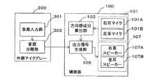
図1は、実施の形態1の補聴装置の構成を示すブロック図である。図1に示すように、第1の実施の形態の補聴装置は、補聴器100と、外部マイクアレー300と、を備える。図3は、実施の形態1の補聴装置の使用例1を示す図であり、図4は、実施の形態1の補聴装置の使用例2を示す図である。(Embodiment 1)
FIG. 1 is a block diagram illustrating a configuration of the hearing aid device according to the first embodiment. As shown in FIG. 1, the hearing aid device of the first embodiment includes a
図2は、図1に示す補聴装置の構成を、詳細に示すブロック図である。図2において図1と同一の参照番号が付与されている構成要素は、図1における構成要素と同一の機能を有する。 FIG. 2 is a block diagram showing in detail the configuration of the hearing aid apparatus shown in FIG. 2, the same reference numerals as those in FIG. 1 are given the same functions as those in FIG.
図1を参照し、実施の形態1の補聴装置の一部を構成する補聴器100の構成を説明する。補聴器100は、右耳に装着する右ユニット及び左耳に装着する左ユニットからなる。左右の各ユニットは、両耳マイク101の各耳用のマイクと、方向感成分算出部103と、出力信号生成部105と、両耳スピーカー107の各耳用のスピーカーから構成される。補聴器100の左右のユニット間は無線で通信する。なお、補聴器100の左右のユニット間は有線で通信するよう構成されても良い。 With reference to FIG. 1, the structure of the
両耳マイク101は、右ユニットの一部を構成する右耳マイク101Aと左ユニットの一部を構成する左耳マイク101Bとから構成される。両耳マイク101は、補聴器100の装着者の左右の耳元で、音源から補聴器100の装着者に到来する音を入力し、音響信号に変換する。 The
方向感成分算出部103は、両耳マイク101で変換された音響信号から、両耳間時間差および両耳間音量差を、音源から前記両耳マイクの装着者に到来する前記音の到来方向を補聴器100の装着者が感じる方向感成分として算出する。つまり、方向感成分は、両耳マイク101の装着者を基点とした音源の方向感を表す。 The directional
両耳間時間差を方向感成分として算出する場合、方向感成分算出部103は、右耳マイク101Aで変換された右の音響信号の時間と左耳マイク101Bで変換された左の音響信号の時間とをずらしながら相互相関値を計算する。そして、相互相関値が最大となる時間を両耳間時間差とする。両耳間音量差を方向感成分として算出する場合、方向感成分算出部103は、両耳間時間差の分だけ、右耳マイク101Aで変換された右の音響信号の時間と左耳マイク101Bで変換された左の音響信号とをずらして、左右の音響信号のパワー比を求める。そして、方向感成分算出部103は、左右の音響信号のパワー比を両耳間音量差とする。 When calculating the interaural time difference as a direction component, the direction
上述のように、方向感成分算出部103は、音源から両耳マイク101に到達する音から、直接的に、音源から到来する音の方向感成分を算出する。そのため、実施の形態1の補聴装置は、音源から到来する音の方向を忠実に再現することができる。なお、方向感成分算出部103は、両耳間時間差及び両耳間音量差のいずれか一方を方向感成分として算出しても良いし、両耳間時間差及び両耳間音量差の両方を方向感成分として算出しても良い。 As described above, the directional
出力信号生成部105は、方向感成分算出部103で算出された方向感成分と、後述する外部マイクアレー300から受信した音源信号とから、左右の各スピーカーから出力するための左右の音響信号を生成する。出力信号生成部105は、方向感成分のひとつである両耳間時間差から、左ユニット及び右ユニットのうち、どちらのユニットが音源から離れているかを判定する。 The output
音源からより離れているユニットに対して出力信号生成部105は、後述する外部マイクアレー300の音源分離部303から受信した音源信号を、両耳間時間差の分だけ遅延させる。さらに、音源からより離れているユニットに対して出力信号生成部105は、当該ユニットの両耳スピーカー107の音量を、両耳間音量差の分だけ小さくするよう制御する。 For a unit farther away from the sound source, the output
また、左右のユニットのうち音源に近いユニットに対して出力信号生成部105は、音源分離部303から受信した音源信号をそのまま両耳スピーカー107へ出力する。 In addition, the output
両耳スピーカー107は、右ユニットの一部を構成する右耳スピーカー107Aと左ユニットの一部を構成する左耳スピーカー107Bとから構成される。両耳スピーカー107は、補聴器100の装着者の左右の耳元で、出力信号生成部105で生成された音源信号を左右の音響信号として出力する。 The
次に、図1を参照し、実施の形態1の補聴装置の一部を構成する外部マイクアレー300の構成を説明する。外部マイクアレー300は、音源入力部301と、音源分離部303と、を備える。実施の形態1の補聴装置では、外部マイクアレー300は、補聴器100の両耳マイク101よりも近い場所に設置される。外部マイクアレー300は、補聴器100の左右のユニット間と、無線で通信する。なお、外部マイクアレー300は、補聴器100の左右のユニット間と、有線で通信するように構成されても良い。 Next, the configuration of an
音源入力部301は、音源から外部マイクアレー300に到来する音を入力し、音響信号に変換する。音源入力部301は、複数のマイクで構成される。
音源入力部301で変換された各マイクの音響信号は、音源分離部303へ転送される。The sound
The sound signal of each microphone converted by the sound
音源分離部303は、各マイクに音源から到来する音の到来時間の差を利用して、外部マイクアレー300を基点とした音源の方向を検出する。 The sound
音源分離部303は、各マイクの空間配置に基づいて、各マイクに対する音の遅延時間を加味し、各マイクの音響信号を加算することで、音源分離部303は、外部マイクアレー300を基点とした音源の方向に指向性処理された音源信号を生成し、補聴器100の出力信号生成部105へ無線で送信する。 The sound
ここで、音源分離部303で生成された音源信号は、外部マイクアレー300を基点として、対象の音源から到来する音を強調(指向性処理)されている。そのため、音源分離部303で生成された音源信号では、対象となる音源の音以外の音が抑圧され、対象となる音源の音が明瞭となっている。なお、外部マイクアレー300の位置が、両耳マイク101の位置より音源の位置に近い場合、音源分離部303で生成される音源信号では、さらに対象となる音源の音が明瞭となっている。 Here, the sound source signal generated by the sound
次に、図3を参照し、実施の形態1の補聴装置の動作例1を説明する。 Next, with reference to FIG. 3, the operation example 1 of the hearing aid apparatus of Embodiment 1 is demonstrated.
(動作例1)
図3に示すように、補聴器100を装着する人物Aと、人物Bと、人物Cとが、中央付近に外部マイクアレー300が設置されている円卓700を囲んで会議をしている。図3では、人物Bが発話をしている間、人物Aは人物Bを斜め右方向に見て人物Bの話を聞いている。(Operation example 1)
As shown in FIG. 3, a person A, a person B, and a person C wearing the
まず、人物Bが発話した音が、2つのマイク系統から入力され、音響信号に変換される。第1のマイク系統は、外部マイクアレー300の音源入力部301を構成する複数のマイクであり、第2のマイク系統は、補聴器100の両耳マイク101である。 First, the sound uttered by the person B is input from two microphone systems and converted into an acoustic signal. The first microphone system is a plurality of microphones constituting the sound
(第1のマイク系統)
外部マイクアレー300の音源入力部301では、発話する人物Bから外部マイクアレー300に到来する音(矢印1)が入力され、音響信号に変換される。外部マイクアレー300の音源入力部301を構成する複数のマイクのそれぞれが、音源である人物Bから到来する人物Bの発話の音を収音する。
音源入力部301で変換された音響信号は、音源分離部303へ転送される。(First microphone system)
In the sound
The acoustic signal converted by the sound
音源分離部303では、各マイクに到来する人物Bの発話の音の到来時間の差を利用して、外部マイクアレー300を基点とした音源の方向を示す音源方向が検出される。
音源分離部303では、各マイクの音響信号が、各マイクの空間配置に基づいて、各マイクに対する音の遅延時間を加味し加算され、外部マイクアレー300を基点とした音源の方向に指向性処理される。そして、指向性処理された音響信号は、外部マイクアレー300を基点とした音源の方向に指向性処理された音源信号として、補聴器100の出力信号生成部105へ無線で送信される。The sound
In the sound
(第2のマイク系統)
補聴器100の両耳マイク101を構成する右耳マイク101A及び左耳マイク101Bではそれぞれ、発話する人物Bから両耳マイク101に到来する音(矢印2A及び矢印2B)が、音響信号に変換される。(Second microphone system)
In the
右耳マイク101A及び左耳マイク101Bで、それぞれ変換された左右の音響信号は、方向感成分算出部103へ転送される。 The left and right acoustic signals respectively converted by the
方向感成分算出部103では、両耳マイク101で変換された左右の音響信号から、両耳間時間差および両耳間音量差のうち少なくともいずれか一方が、両耳マイク101の装着者を基点とした音源の方向を示す方向感成分として、算出される。図3に示す動作例1では、人物Aは、音源である人物Bを右側に見ているので、右耳マイク101Aを基準にした両耳時間差はプラスの値、両耳音量差(パワー比)は1以下の値となる(矢印2Bは矢印2Aよりも長い)。方向感成分算出部103で算出された方向感成分は、出力信号生成部105へ転送される。 In the directional
出力信号生成部105では、方向感成分算出部103で算出された方向感成分と外部マイクアレー300を基点とした音源の方向に指向性処理された音源信号とから、両耳スピーカー107から出力するための左右の音響信号が生成される。 The output
図3に示す動作例1では、人物Aの左耳が人物Aの右耳より人物Bから離れている。そのため、出力信号生成部105では、人物Aの左耳スピーカー107Bから出力される左の音響信号が、方向感成分である両耳間時間差の分だけ遅延される。 In the operation example 1 shown in FIG. 3, the left ear of the person A is farther from the person B than the right ear of the person A. Therefore, in the output
また、出力信号生成部105では、左の音響信号を出力するための左耳スピーカー107Bの音量が、両耳間音量差の分だけ小さくなるよう左耳スピーカー107Bが制御される。 Further, the output
また、出力信号生成部105では、音源分離部303から受信した音源信号が、右の音響信号として、右耳スピーカー107Aから出力するために右耳スピーカー107Aへ転送される。 In the output
上述のように、両耳スピーカー107の左耳スピーカー107B及び右耳スピーカー107Aから出力される音響信号では、(1)方向感成分算出部103で算出され、両耳マイク101の装着者を基点とした音源の方向感を表す方向感成分により、音源である人物Bの発話の音が到来する方向が忠実に再現され、かつ(2)外部マイクアレー300を基点とした音源の方向に指向性処理された音源信号により、音源である人物Bの発話の音声の明瞭性が高められている。 As described above, in the acoustic signals output from the
次に、図4を参照し、実施の形態1の補聴装置の動作例2を説明する。 Next, with reference to FIG. 4, the operation example 2 of the hearing aid apparatus of Embodiment 1 is demonstrated.
(動作例2)
図4に示すように、補聴器100を装着する人物Aと、人物Bと、人物Cとが、中央付近に外部マイクアレー300が設置されている円卓700を囲んで会議をしているとする。図4では、図3に示す状態から、人物Bが発話をやめ、人物Aが外部マイクアレー300を正面に見ていたのを、発話を開始した人物Cを正面に見る方に向きなおし、人物Cの発話を聞いている。(Operation example 2)
As shown in FIG. 4, it is assumed that a person A, a person B, and a person C wearing the
まず、人物Cの発話した音が、2つのマイク系統から入力され、音響信号に変換される。第1のマイク系統は、外部マイクアレー300の音源入力部を構成する複数のマイクであり、第2のマイク系統は、補聴器100の両耳マイク101である。 First, the sound spoken by the person C is input from two microphone systems and converted into an acoustic signal. The first microphone system is a plurality of microphones constituting the sound source input unit of the
(第1のマイク系統)
外部マイクアレー300の音源入力部301では、発話する人物Cから外部マイクアレー300に到来する音が(矢印3)入力され、音響信号に変換される。
外部マイクアレー300の音源入力部301を構成する複数のマイクのそれぞれが、音源である人物Cから到来する人物Cの発話の音を収音する。(First microphone system)
In the sound
Each of the plurality of microphones constituting the sound
音源分離部303では、各マイクに到来する人物Cの発話の音の到来時間の差を利用して、外部マイクアレー300を基点とした音源の方向を示す音源方向が検出される。 The sound
音源分離部303では、各マイクの音響信号が、各マイクの空間配置に基づいて、各マイクに対する音の遅延時間を加味して加算され、外部マイクアレー300を基点とした音源の方向に指向性処理される。そして、指向性処理された音響信号は、外部マイクアレー300と基点とした音源の方向に指向性処理された音源信号として、補聴器100の出力信号生成部105へ無線で送信される。 In the sound
(第2のマイク系統)
補聴器100の両耳マイク101を構成する右耳マイク101A及び左耳マイク101Bではそれぞれ、発話する人物Cから両耳マイク101に到来する音(矢印4A及び矢印4B)が、入力され、音響信号に変換される。
右耳マイク101A及び左耳マイク101Bで、それぞれ変換された左右の音響信号は、方向感成分算出部103へ転送される。(Second microphone system)
In the
The left and right acoustic signals respectively converted by the
方向感成分算出部103では、両耳マイク101で変換された左右の音響信号から、両耳間時間差および両耳間音量差のうち少なくともいずれか一方が、両耳マイク101の装着者を基点とした音源の方向感を表す方向感成分として、算出される。図4に示す動作例2では、人物Aは、人物Cを左に見る方向から人物Cを正面に見る方向に向きなおしているので、両耳時間差は、左耳マイク101Bを基準とするとプラスの値から0に、両耳音量差(パワー比)は1より小さい値から1に、それぞれ変化する(矢印4Aと矢印4Bの長さが等しくなる)。方向感成分算出部103で算出される方向感成分は、出力信号生成部105へ転送される。 In the directional
出力信号生成部105では、方向感成分算出部103で算出された方向感成分と外部マイクアレー300を基点とした音源の方向に指向性処理された音源信号とから、両耳スピーカー107から出力するための左右の音響信号が生成される。 The output
両耳スピーカー107の左耳スピーカー107B及び右耳スピーカー107Aから、出力信号生成部105で合成された左右の音響信号が出力される。 The left and right acoustic signals synthesized by the output
図4に示す動作例2では、人物Aが外部マイクアレー300を正面に見る方向から人物Cを正面に見る方向に向きなおす間、出力信号生成部105では、方向感成分である両耳間時間差が測定値から算出される値からゼロに変化する。さらに、出力信号生成部105は、右耳スピーカー107Aの音量を、両耳間音量差の分だけ小さくするよう右耳スピーカー107Aを制御し、次第に左と等しくする。そのため、人物Aが外部マイクアレー300を正面に見ているとき、右耳の右耳スピーカー107Aからは左耳の左耳スピーカー107Bと比べて人物Cの発話が遅れて小さく音が出力されている。しかし、人物Aが外部マイクアレー300を正面に見る方向から人物Cを正面に見る方向に向きなおすにつれて、左耳スピーカー107Bだけでなく右耳の右耳スピーカー107Aからも人物Cの発話が遅れずに同じ大きさの音が出力されるように変化する。そして、人物Aは人物Cを正面から見たとき、人物Aは正面から人物Cの発話が正面から聞こえるようになる。 In the operation example 2 illustrated in FIG. 4, while the person A turns from the direction in which the
言い換えると、人物Aに対する人物Cの発話による音像は、補聴器100の装着者である人物Aの動きに応じて動かない。 In other words, the sound image of the utterance of the person C with respect to the person A does not move according to the movement of the person A who is wearing the
上述のように動作例2において、本実施の形態1の補聴装置では、人物Aに対する人物Cの発話による音像は、補聴器100を装着する人物Aの動きに応じて動かない。 As described above, in the operation example 2, in the hearing aid device according to the first embodiment, the sound image generated by the utterance of the person C with respect to the person A does not move according to the movement of the person A wearing the
また、両耳スピーカー107の左耳スピーカー107B及び右耳スピーカー107Aから出力される音響信号では、(1)方向感成分算出部103で算出され、両耳マイク101の装着者を基点とした音源の方向を示す方向感成分により、音源である人物Cの発話の音声が到来する方向が忠実に再現され、かつ(2)外部マイクアレー300を基点とした音源の方向に指向性処理された音源信号により、音源である人物Cの発話の音声の明瞭性が高められている。したがって、実施の形態1の補聴装置は、話者の発話する音声が到来する方向を再現しつつ、当該話者の発話する音声の明瞭性を高めることができる。 Also, in the acoustic signals output from the
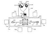
図5は、本実施の形態1の補聴装置の構成図、及び補聴装置を用いた会議システムの構成図を示す。 FIG. 5 shows a configuration diagram of the hearing aid device according to the first embodiment and a configuration diagram of a conference system using the hearing aid device.
補聴装置は、補聴器100と外部マイクアレー300とを含む。補聴器100は、補聴器本体110と、右耳マイク101A及び右耳スピーカー107A、並びに左耳マイク101B及び左耳スピーカー107Bとを含み、互いに有線によって接続される。外部マイクアレー300は、スピーカーホン本体310と2つの外部マイク320とを含み、2つの外部マイク320とスピーカーホン本体310とは、有線L1によって接続される。スピーカーホン本体310は、4つの内蔵マイク330を含む。補聴器100に含まれる補聴器本体110と、外部マイクアレー300に含まれるスピーカーホン本体310とは、有線L2によって接続される。 The hearing aid device includes a
補聴器本体110、及びスピーカーホン本体310は、それぞれ、電源、DSP(Digital Signal Processor)、通信部、記憶部、制御部を含む。 Each of the hearing aid
図5に示すように、補聴装置を用いた会議システムは、補聴装置、机710、及び複数の椅子720から構成される。複数の椅子720は、机710の周りに設置される。椅子720に座る話者の音声は、外部マイクアレー300、並びに右耳マイク101A及び左耳マイク101Bに入力される。話者の音声は、外部マイクアレー300を介して、明瞭性の高い音声成分として両耳スピーカー107に出力される。また、話者の音声は、右耳マイク101A及び左耳マイク101Bを介して、方向感成分として両耳スピーカー107に出力される。補聴装置の利用者は、明瞭性の高い音声成分と方向感成分とに基づいて、話者の音声を明瞭に、かつ到来方向を知覚して聞くことができる。 As shown in FIG. 5, the conference system using the hearing aid device includes a hearing aid device, a
なお、以上の説明は、有線L1、L2によって各部が接続されているものとしたが、無線によって各部が接続されてもよい。例えば、右耳マイク101Aと右耳スピーカー107Aと、を備える右耳ユニット110R、左耳マイク101Bと左耳スピーカー107Bとを備える左耳ユニット110L、及び外部マイクアレー300のそれぞれが、電源、DSP、通信部、記憶部、制御部などを含み、互いに無線で通信するとしてもよい。 In the above description, each unit is connected by the wires L1 and L2, but each unit may be connected wirelessly. For example, a right ear unit 110R including a
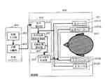
また、図6に示すように、図5に示す、補聴装置を用いた会議システムにおいて、補聴器100にリモコンユニット130を加えてもよい。図6中、無線で通信する部分を破線で示した。リモコンユニット130は、補聴器100の出力音量を変更するなどのユーザーによる制御が基本機能であるが、4つのマイク131で構成されるマイクアレーを実装することにより、外部マイクアレー300としても利用できるようになる。このリモコンユニット130は、たとえば、携帯電話150上に実装することができる。 Further, as shown in FIG. 6, a
有線であるか無線であるか、また補聴装置に含まれる各ユニットの構成によらず、いずれの場合にも、補聴装置における情報処理は、通信による処理遅延や電力消費量などを考慮して、補聴器100と外部マイクアレー300とに含まれる複数のユニット間で適切に分散されるのが望ましい。 Regardless of the configuration of each unit included in the hearing aid device, whether wired or wireless, the information processing in the hearing aid device takes into account the processing delay due to communication, power consumption, etc. It is desirable that the plurality of units included in the
例えば、図5では、図1のブロック構成に従い、スピーカーホン本体310が内蔵するDSPが音源入力処理及び音源分離処理を行い、補聴器本体110が内蔵するDSPがその他の処理を行えばよい。これにより、外部マイクアレー300と補聴器100との間の通信信号は、分離された音声信号だけを含めばよく、通信容量が少なくて済むという効果がある。また、処理量の多い音源分離を、ACアダプターを利用可能なスピーカーホン本体310で行うことにより、補聴器本体110の電力消費量を抑えられるという効果がある。 For example, in FIG. 5, according to the block configuration of FIG. 1, the DSP built in the speakerphone
また、例えば、図6では、無線通信に伴う処理遅延が、有線通信よりも顕著になるので、通信量に配慮した方がよい。 Further, for example, in FIG. 6, the processing delay associated with wireless communication becomes more prominent than that of wired communication, so it is better to consider the amount of communication.
方向感成分として両耳間音量差が用いれば、左右の音量のそれぞれと所定の基準音量との差を用いて左右の出力信号の音量を決定することができる。これによって、補聴器本体110の左右ユニットからリモコンユニット130への信号の送信による処理遅れは生じないため、方向感成分が自然のままに保たれるという効果がある。さらに、左右の音量の直接比較は不要となるため、補聴器本体110の右ユニット内で右の出力信号を生成し、補聴器本体110の左ユニット内で左の出力信号を生成し、左右独立に処理を行うことが可能となるので、左右の通信に伴う処理遅れについても生じないという効果がある。 If the interaural volume difference is used as the directional component, the volume of the left and right output signals can be determined using the difference between each of the left and right volumes and a predetermined reference volume. As a result, there is no processing delay due to the transmission of signals from the left and right units of the hearing aid
なお、本実施の形態1の補聴装置の補聴器100の形は特に限定されるものでない。しかし例えば、本実施の形態1の補聴装置の補聴器100の形をカナル型にすれば、本実施の形態1の補聴装置は、両耳マイク101の装着者の頭部の向きだけでなく、補聴器100の装着者の各部位(耳介、肩、胴体)の大きさや形に依存する反射による影響を反映させた方向感成分を生成することができる。 Note that the shape of the
なお、本実施の形態1の補聴装置では、外部マイクアレー300を円卓700の中央付近に設置しているが、これに限らない。各話者がヘッドセット型の外部マイクアレー300を装着しても良い。この場合、外部マイクアレーは、音源入力部301で構成され、音源分離部303は必要ない。 In the hearing aid device according to the first embodiment, the
なお、本実施の形態1の補聴装置では、両耳スピーカー107は、例えば、ヘッドホンに内蔵しても良い。 In the hearing aid device according to the first embodiment, the
なお、本実施の形態1の補聴装置では、両耳マイク101は、例えば、ヘッドホンに内蔵しても良い。 In the hearing aid device according to the first embodiment, the
なお、本実施の形態1の補聴装置では、外部マイクアレー300の音源入力部301を一つのマイクで構成し、外部マイクアレー300を両耳マイク101よりも、音源の近くに配置しても良い。 In the hearing aid device according to the first embodiment, the sound
(実施の形態2)
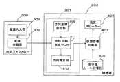
図7は、実施の形態2の補聴装置の構成を示すブロック図である。また、図8は、実施の形態2の補聴装置の構成を、詳細に示すブロック図である。図7に示すように、第2の実施の形態の補聴装置は、補聴器200と、外部マイクアレー400と、を備える。図9は、実施の形態2の補聴装置の使用例を示す図である。(Embodiment 2)
FIG. 7 is a block diagram illustrating a configuration of the hearing aid device according to the second embodiment. FIG. 8 is a block diagram showing in detail the configuration of the hearing aid device of the second embodiment. As shown in FIG. 7, the hearing aid device of the second embodiment includes a
図7を参照し、実施の形態2の補聴装置の一部を構成する補聴器200の構成を説明する。実施の形態2の補聴装置の両耳マイク及び両耳スピーカーは、実施の形態1の両耳マイク101及び両耳スピーカー107とその構成が同じである。そのため、図1と同じ参照番号が付されている。 With reference to FIG. 7, the structure of the
補聴器200は、右耳に装着する右ユニット及び左耳に装着する左ユニットからなる。左右の各ユニットは、両耳マイク101と、出力信号生成部205と、両耳伝達特性計測部207と、音源位置推定部209と、両耳スピーカー107と、音声検出部211とから構成される。補聴器200の左右のユニット間は無線で通信する。なお、補聴器200の左右のユニット間は有線で通信するよう構成されても良い。 The
両耳マイク101は、右ユニットの一部を構成する右耳マイク101Aと左ユニットの一部を構成する左耳マイク101Bとから構成される。両耳マイク101は、補聴器200の装着者の左右の耳元で、音源から補聴器200の装着者に到来する音を入力し、音響信号に変換する。そして、変換された音響信号は、補聴器200装着者の左右の耳の伝達関数を求めるために、両耳伝達特性計測部207へ転送される。 The
音声検出部211は、後述するように、外部マイクアレー400の音源分離部403で分離された各音源信号を受信し、その音源信号から発話している人物の音声を検出する。音声検出部211は、音源ごとに分離された音源信号毎に所定の時間区間のパワーを求める。そして、所定の時間区間のパワーが閾値以上である音源を、発話している人物の音声として検出する。なお、音声検出部211は、発話している人物の音声を検出する場合に用いる音源信号の要素として、パワーに加えて、調波構造を表すパラメータ(例えば、ピッチを仮定した櫛型フィルタによるパワーと広帯域パワーの比)を用いても良い。 As will be described later, the
両耳伝達特性計測部207は、発話している人物の音声として音声検出部211で検出された音源信号(以下、音声信号と記載)と右耳マイク101Aからひろった右の音響信号との間の伝達関数(以下、右の伝達特性と記載)を求める。同様に、両耳伝達特性計測部207は、音声信号と左耳マイク101Bからひろった左の音響信号との間の伝達関数(以下、左の伝達特性と記載)を求める。両耳伝達特性計測部207は、各耳の伝達特性と、外部マイクアレー400を基点とした音源の方向を示す方向(以下、音源方向と記載)とを対応付ける。そのため、音声として検出された音声信号が複数ある場合でも、両耳伝達特性計測部207は、各音源の音源方向を表現できる。 The binaural transfer
なお、実施の形態2の補聴装置において、実施の形態1における方向感成分は、両耳伝達特性計測部207で求められる各耳の伝達特性が相当する。 In the hearing aid of the second embodiment, the direction sense component in the first embodiment corresponds to the transmission characteristics of each ear obtained by the binaural transmission
なお、複数人の発話者が同時に発話している場合、すわなち、音声検出部211が、音源ごとに分離された音源信号を複数同時に検出した場合、両耳伝達特性計測部207は、各耳の伝達関数の計測を停止する。その場合、各耳の伝達関数の計測を停止する直前の伝達関数を利用することで、各人物の音源方向感を保持できる。 When a plurality of speakers are speaking at the same time, that is, when the
音源位置推定部209は、両耳伝達特性計測部207で求められた、音源方向と対応付けられた左右の耳の伝達関数に基づき、各音源の位置を推定することができる。 The sound source
まず、音源位置推定部209は、音源方向と対応付けられた各耳の伝達関数のインパルス応答上で、最初のピークを持つ時間から、外部マイクアレー400から両耳マイク101までの音の到達時間を求める。この到達時間から、補聴器200の装着者からの各音源の遠近を推定することができる。さらに、音源位置推定部209は、左右の耳の伝達関数のインパルス応答から時間をずらしながら相互相関値を計算し、相互相関値が最大となる時間を両耳間時間差として求める。 First, the sound source
そして、音源位置推定部209は、複数の音源のうち、到達時間が最小の値を持ち、かつ、両耳間時間差が0に近い音源を補聴器200の装着自身の発話とする。したがって、音源位置推定部209は、両耳伝達特性計測部207で求められた、音源方向と対応付けられた左右の耳の伝達関数に基づき、各音源の位置を推定することができる。そして、音源位置推定部209の推定結果は、出力信号生成部205で参照される。
上述のように、実施の形態2の補聴装置では、音声検出部211と、両耳伝達特性計測部207と、音源位置推定部209とが、実施の形態1の方向感成分算出部と同じ機能を備えている。Then, the sound source
As described above, in the hearing aid device according to the second embodiment, the
出力信号生成部205は、両耳伝達特性計測部207で計測された左右の伝達特性と、及び左右の音声信号とから、それぞれ両耳スピーカー107の右耳スピーカー107A及び左耳スピーカー107Bから出力するための左右の音響信号を生成する。出力信号生成部205は、第1のマイク系統の音声信号に、左右の伝達特性を表す伝達関数のインパルス応答を畳み込んで、左右の音響信号を生成する。 The output
なお、出力信号生成部205は、必要に応じて音源位置推定部209の推定結果を参照し、左右の音声信号の音源が、補聴器200の装着者自身であるかどうかを判断する。音源位置推定部209で、音源が補聴器200の装着自身と判断された場合、出力信号生成部205は、第1のマイク系統の音声信号は両耳スピーカー107へ出力せず、第2のマイク系統の音声信号を両耳スピーカー107へ出力する。これによって、装着者自信の声も明瞭でかつ時間遅れの少ない音声を違和感なく聞くことができる。 Note that the output
両耳スピーカー107は、右ユニットの一部を構成する右耳スピーカー107Aと左ユニットの一部を構成する左耳スピーカー107Bとから構成される。両耳スピーカー107は、補聴器200の装着者の左右の耳元で、出力信号生成部205で生成された音源信号を左右の音響信号として出力する。 The
次に、図7、図8を参照し、実施の形態2の補聴装置の一部を構成する外部マイクアレー400の構成を説明する。実施の形態2の補聴装置において、外部マイクアレーの音源入力部301は、実施の形態1の外部マイクアレーの音源入力部と同じ構成である。そのため、図1と同じ参照番号が付されている。 Next, the configuration of the
外部マイクアレー400は、音源入力部301と、音源分離部403と、を備える。実施の形態2の補聴装置において、外部マイクアレー400は、補聴器200の両耳マイク101よりも、発話者B、Cに近い場所に設置される。外部マイクアレー400は、補聴器200の左右のユニット間と、無線で通信する。なお、外部マイクアレー400は、補聴器200の左右のユニット間と、有線で通信するように構成されても良い。 The
音源入力部301は、音源から外部マイクアレー400に到来する音を入力し、響信号に変換する。音源入力部301は、複数のマイクで構成される。
音源入力部301で変換された各マイクの音響信号は、音源分離部403へ転送される。The sound
The sound signal of each microphone converted by the sound
音源分離部403は、各マイクに音源から到来する音の到来時間の差を利用して、外部マイクアレー400を基点とした音源の方向を検出する。 The sound
音源分離部403は、各マイクの空間配置に基づいて、各マイクに対する音の遅延時間を加味し、各マイクの音響信号を加算する。そして、音源分離部303は、このように外部マイクアレー400を基点とした音源の方向に指向性処理された音源信号を生成し、補聴器200の音声検出部211へ無線で送信する。 The sound
ここで、音源分離部403で生成された音源信号は、外部マイクアレー400を基点として、対象の音源から到来する音を強調(指向性処理)されている。そのため、音源分離部403で生成された音源信号では、対象となる音源の音以外の音が抑圧され、対象となる音源の音が明瞭となっている。なお、外部マイクアレー400の位置が、両耳マイク101の位置より音源の位置に近い場合、音源分離部303で生成される音源信号では、さらに対象となる音源の音が明瞭となっている。 Here, the sound source signal generated by the sound
なお、音源分離部403は、独立成分分析による音源分離を行うようにしてもよい。その際、音声検出部211でパワーを利用するために、分離行列の逆行列の対角要素をそれぞれの独立成分に乗じて、パワー情報を復元しておく。 Note that the sound
(動作例)
図9に示すように、補聴器200を装着する人物Aと、人物Bと、人物Cとが、中央付近に外部マイクアレー400が設置されている円卓700を囲んで会議をしているとする。図9では、人物B、人物Cが発話をしている間、人物Aは人物Bを正面に見て人物Bの話を聞いている。(Operation example)
As shown in FIG. 9, it is assumed that a person A, a person B, and a person C wearing the
人物B及び人物C及び人物Aの発話の音が、2つのマイク系統から入力され、左右の音響信号に変換される。第1のマイク系統は、外部マイクアレー400の音源入力部を構成する複数のマイクであり、第2のマイク系統は、補聴器200の両耳マイク101である。 The sounds of the utterances of person B, person C, and person A are input from the two microphone systems and converted into left and right acoustic signals. The first microphone system is a plurality of microphones constituting the sound source input unit of the
(第1のマイク系統)
外部マイクアレー400の音源入力部301では、人物Bから外部マイクアレー400に到来する音(矢印5)が入力され、音響信号に変換される。同様に、外部マイクアレー400の音源入力部301では、人物Cから外部マイクアレー400に到来する音(矢印7)が、音響信号に変換される。また、外部マイクアレー400の音源入力部301では、人物Aから外部マイクアレー400に到達する音(矢印9)についても、音響信号に変換される。外部マイクアレー400の音源入力部301を構成する複数のマイクのそれぞれが、音源である人物B及び人物C及び人物Aからそれぞれ到来する発話の音を収音する。音源入力部301で音響信号に変換された音響信号は、音源分離部403へ転送される。(First microphone system)
In the sound
音源分離部403では、例えば、各マイクに到来する人物Bの発話の音の到来時間の差を利用して、外部マイクアレー400を基点とした音源の方向を示す音源方向が検出される。 The sound
音源分離部403では、各マイクの音響信号が、各マイクの空間配置に基づいて、各マイクに対する音の遅延時間を加味し加算され、外部マイクアレー400を基点とした音源の方向に指向性処理される。そして、指向性処理された音響信号は、外部マイクアレー400を基点とした音源の方向に指向性処理された音源信号として、補聴器200の音声検出部211へ無線で送信される。 In the sound
(第2のマイク系統、補聴器200)
補聴器200の両耳マイク101の左右のマイク101A、101Bでは、各音源から到来する各人物(人物B又は人物C又は人物A)の発話の音(矢印6A、矢印8A、矢印10A、矢印6B、矢印8B、矢印10B)が入力され、それぞれ音響信号に変換される。
変換された各音源の音響信号は、各マイク101A、101Bから、両耳伝達特性計測部207へ転送される。(Second microphone system, hearing aid 200)
In the left and
The converted acoustic signals of the sound sources are transferred from the
また、音声検出部211では、外部マイクアレー400の音源分離部403から受信した各音源信号から各人物B、人物C、人物Aの音声が検出される。 Further, the
また、音声検出部211では、音源ごとに分離された音源信号毎に所定の時間区間のパワーを求める。そして、所定の時間区間のパワーが閾値以上である音源を、発話している人物の音声として検出する。検出された発話人物の音声は、音源分離部403で指向性処理された音源信号から検出されているので、非常に明瞭となっている。 Further, the
発話している人物の音声が検出された各音源信号(以下、音声信号と記載)は、両耳伝達特性計測部207へ転送される。 Each sound source signal (hereinafter referred to as an audio signal) from which the voice of the person who is speaking is detected is transferred to the binaural transfer
両耳伝達特性計測部207では、音声検出部211から転送された各音源(人物B又は人物Cまたは人物A)の音声信号のそれぞれと右耳マイク101Aから転送された音響信号との間の伝達関数が求められる。同様に、両耳伝達特性計測部207では、音声検出部211から転送された各音源(人物B又は人物C)の音声信号のそれぞれと左耳マイク101Bから転送された音響信号との間の伝達関数が求められる。 In the binaural transfer
また、両耳伝達特性計測部207では、各音源の(人物B、人物C、人物A)の各耳の伝達特性と外部マイクアレー400を基点とした音源の方向を示す音源方向とが対応付けられている。 Also, the binaural transfer
なお、二人以上の人物が同時に発話している場合、両耳伝達特性計測部207では、各耳の伝達関数の計測が停止される。その場合、各耳の伝達関数の計測を停止する直前の伝達関数を使用する。 When two or more persons are speaking at the same time, the binaural transfer
音源方向と対応付けられた各音源の各耳の伝達特性は、出力信号生成部205及び音源位置推定部209へ転送される。 The transfer characteristics of each ear of each sound source associated with the sound source direction are transferred to the output
音源位置推定部209では、両耳伝達特性計測部207で求められた、外部マイクアレー400を基点とした音源の方向を示す音源方向と対応付けられた左右の耳の伝達関数に基づき、各音源の位置を推定することができる。 In the sound source
なお、図9では、補聴器200の装着者である人物Aの発話は、複数の音源のうち、到達時間が最小の値を持ち(矢印10Bと矢印9の長さの差が、矢印6Bと矢印5の長さの差や矢印8Bと矢印7の長さよりも小さい)、かつ、両耳間時間差が0に近い(矢印10Aと矢印10Bの長さがほぼ等しい)音源として検出される。 In FIG. 9, the utterance of the person A who is wearing the
出力信号生成部205では、各音源の左右の音声信号のそれぞれに、音源方向と対応付けられた各音源の各耳の伝達特性を表す伝達関数のインパルス応答を畳み込んで、両耳スピーカー107の右耳スピーカー107A及び左耳スピーカー107Bから出力するため左右の音響信号を合成する。図9では、音源位置推定部209が、補聴器200の装着者である人物Aの発話が検出されると、出力信号生成部205では、第2のマイク系統の音声信号を両耳スピーカー107へ出力する。 The output
両耳スピーカー107では、出力信号生成部205で合成された左右の音響信号が、それぞれ右耳スピーカー107A及び左耳スピーカー107Bから出力される。 In the
上述のように、実施の形態2の補聴装置では、外部マイクアレー400で処理された各音源の音が明瞭となっている左右の音声信号と、補聴器200の両耳伝達特性計測部207で求められ、音源方向が対応付けられた左右の伝達関数とから生成された左右の音響信号を両耳スピーカー107から出力する。そのため、実施の形態2の補聴装置は、話者の発話する音声が到来する方向を再現しつつ、当該話者の発話する音声の明瞭性を高めることができる。 As described above, in the hearing aid device of the second embodiment, the left and right audio signals in which the sound of each sound source processed by the
また、実施の形態2の補聴装置において、補聴器200の形は特に限定されるものでないが、例えばカナル型を用いると、出力信号生成部205で合成された左右の音響信号は、発話している人物が補聴器200を装着している頭部の向きだけでなく、発話している人物の各部位(耳介、肩、胴体)の大きさや形から反射による影響を左右の伝達特性に含む。そのため、実施の形態2の補聴装置において、補聴器200の装着者は、両耳スピーカー107から出力される音の方向感をリアルタイムに感じることができる。 Further, in the hearing aid device of the second embodiment, the shape of the
なお、実施の形態2における補聴装置についても、実施の形態1において図5で示した補聴装置の構成図、及び会議システムの構成図を適用できる。 The configuration diagram of the hearing aid device and the configuration diagram of the conference system shown in FIG. 5 in the first embodiment can also be applied to the hearing aid device in the second embodiment.
本出願は、2009年1月22日出願の日本特許出願(特願2009−012292)に基づくものであり、その内容はここに参照として取り込まれる。 This application is based on a Japanese patent application filed on January 22, 2009 (Japanese Patent Application No. 2009-012292), the contents of which are incorporated herein by reference.
本発明に係る補聴装置は、逆写像ルールを用いずに、話者の発話する音声が到来する方向を再現しつつ、当該話者の発話する音声の明瞭性を高めることができるという効果を有し、補聴装置等として有用である。 The hearing aid according to the present invention has an effect of improving the clarity of the speech uttered by the speaker while reproducing the direction in which the speech uttered by the speaker arrives without using the inverse mapping rule. It is useful as a hearing aid.
100、200、800 補聴器
101 両耳マイク
101A 右耳マイク
101B 左耳マイク
103、203 方向感成分算出部
105、205 出力信号生成部
107、801 両耳スピーカー
107A 右耳スピーカー
107B 左耳スピーカー
110 補聴器本体
130 リモコンユニット
207 両耳伝達特性計測部
209 音源位置推定部
211 音声検出部
300、400、900 外部マイクアレー
301、901 音源入力部
303、403、902 音源分離部
310 スピーカーホン本体
320 外部マイク
700 円卓
710 机
720 複数の椅子
803 仮想音像回転部
805 逆写像ルール記憶部
807 頭部角度センサ
809 方向基準設定部
813 方向推定部100, 200, 800
Claims (3)
Translated fromJapanese前記外部マイクアレーは、音源から到来する音を入力して第1音響信号に変換する音源入力部と、前記音源入力部で変換された前記第1音響信号を、各音源に対応した音源信号に分離する音源分離部と、を備え、
前記補聴器は耳かけ式であって、左右の耳元に配置され、前記音源から到来する前記音を入力して第2音響信号に変換する両耳マイクと、前記両耳マイクで変換された左右の前記第2音響信号から、前記両耳マイクを基点とした前記音源の方向感を表す方向感成分を算出する方向感成分算出部と、前記音源信号及び前記方向感成分に基づいて、左右の出力音響信号を生成する出力信号生成部と、前記出力信号生成部で生成された前記左右の出力音響信号を出力する両耳スピーカーと、を備える、
補聴装置。A hearing aid device comprising an external microphone array and a hearing aid,
The external microphone array receives a sound coming from a sound source and converts it into a first sound signal, and converts the first sound signal converted by the sound source input portion into a sound source signal corresponding to each sound source. A sound source separation unit for separating,
The hearing aid is an ear-mounted type and is arranged at the leftand right ears, inputs a sound coming from the sound source and converts it into a second acoustic signal, and a left and right microphone converted by the binaural microphone. Based on the sound source signal and the directional component, left and right outputs based on the directional component calculating unit that calculates a directional component that represents the directional sense of the sound source with the binaural microphone as a base point from the second acoustic signal. an output signal generator for generating an acoustic signal, a binaural speakers for outputting an output sound signal of the left and right generated by the output signal generation unit,Ru providedwith,
Hearing aid device.
前記出力信号生成部は、前記音源信号及び前記音量差に基づいて、左右独立に前記出力音響信号を生成する、The output signal generation unit generates the output acoustic signal independently on the left and right based on the sound source signal and the volume difference.
請求項1に記載の補聴装置。The hearing aid according to claim 1.
前記音源入力部で変換された前記第1音響信号を、各音源に対応した音源信号に分離する音源分離部と、A sound source separation unit that separates the first acoustic signal converted by the sound source input unit into a sound source signal corresponding to each sound source;
左耳元に配置され、前記音源から到来する前記音を入力して左第2音響信号に変換する左耳マイクと、A left ear microphone that is arranged at the left ear and that inputs the sound coming from the sound source and converts it into a second left acoustic signal;
右耳元に配置され、前記音源から到来する前記音を入力して右第2音響信号に変換する右耳マイクと、A right ear microphone that is arranged near the right ear and that inputs the sound coming from the sound source and converts it into a right second acoustic signal;
前記左第2音響信号から前記左耳マイクを起点とした前記音源の方向感を表す左方向感成分と、前記右第2音響信号から前記右耳マイクを起点とした前記音源の方向感を表す右方向感成分とを算出する方向感成分算出部と、A left direction component representing the direction of the sound source starting from the left ear microphone from the left second acoustic signal and a direction sense of the sound source starting from the right ear microphone from the right second acoustic signal. A direction sense component calculation unit for calculating a right direction sense component;
前記音源信号及び前記左方向感成分に基づいて左出力音響信号と、前記音源信号及び前記右方向感成分に基づいて右出力音響信号とを生成する出力信号生成部と、An output signal generation unit that generates a left output acoustic signal based on the sound source signal and the left direction sense component, and a right output acoustic signal based on the sound source signal and the right direction sense component;
前記左出力音響信号を出力する左耳スピーカーと、A left ear speaker that outputs the left output acoustic signal;
前記右出力音響信号を出力する右耳スピーカーと、A right ear speaker that outputs the right output acoustic signal;
を備え、With
前記方向感成分算出部は、前記左第2音響信号の音量と所定の基準音量との音量差である左音量差と、前記右第2音響信号の音量と前記所定の基準音量との音量差である右音量差とを、独立に算出し、The directional component calculation unit includes a left volume difference that is a volume difference between the volume of the left second acoustic signal and a predetermined reference volume, and a volume difference between the volume of the right second acoustic signal and the predetermined reference volume. The right volume difference is calculated independently,
前記出力信号生成部は、前記音源信号及び前記左音量差に基づいて前記左出力音響信号と、前記音源信号及び前記右音量差に基づいて前記右出力音響信号とを、独立に生成する、The output signal generation unit independently generates the left output acoustic signal based on the sound source signal and the left volume difference, and the right output acoustic signal based on the sound source signal and the right volume difference.
補聴装置。Hearing aid device.
Priority Applications (1)
| Application Number | Priority Date | Filing Date | Title |
|---|---|---|---|
| JP2013152673AJP5642851B2 (en) | 2009-01-22 | 2013-07-23 | Hearing aid |
Applications Claiming Priority (3)
| Application Number | Priority Date | Filing Date | Title |
|---|---|---|---|
| JP2009012292 | 2009-01-22 | ||
| JP2009012292 | 2009-01-22 | ||
| JP2013152673AJP5642851B2 (en) | 2009-01-22 | 2013-07-23 | Hearing aid |
Related Parent Applications (1)
| Application Number | Title | Priority Date | Filing Date |
|---|---|---|---|
| JP2010547444ADivisionJP5409656B2 (en) | 2009-01-22 | 2010-01-22 | Hearing aid |
Publications (2)
| Publication Number | Publication Date |
|---|---|
| JP2013236396A JP2013236396A (en) | 2013-11-21 |
| JP5642851B2true JP5642851B2 (en) | 2014-12-17 |
Family
ID=42355824
Family Applications (2)
| Application Number | Title | Priority Date | Filing Date |
|---|---|---|---|
| JP2010547444AActiveJP5409656B2 (en) | 2009-01-22 | 2010-01-22 | Hearing aid |
| JP2013152673AActiveJP5642851B2 (en) | 2009-01-22 | 2013-07-23 | Hearing aid |
Family Applications Before (1)
| Application Number | Title | Priority Date | Filing Date |
|---|---|---|---|
| JP2010547444AActiveJP5409656B2 (en) | 2009-01-22 | 2010-01-22 | Hearing aid |
Country Status (3)
| Country | Link |
|---|---|
| US (1) | US8670583B2 (en) |
| JP (2) | JP5409656B2 (en) |
| WO (1) | WO2010084769A1 (en) |
Families Citing this family (101)
| Publication number | Priority date | Publication date | Assignee | Title |
|---|---|---|---|---|
| US9318108B2 (en) | 2010-01-18 | 2016-04-19 | Apple Inc. | Intelligent automated assistant |
| US8977255B2 (en) | 2007-04-03 | 2015-03-10 | Apple Inc. | Method and system for operating a multi-function portable electronic device using voice-activation |
| US8676904B2 (en) | 2008-10-02 | 2014-03-18 | Apple Inc. | Electronic devices with voice command and contextual data processing capabilities |
| US20120309363A1 (en) | 2011-06-03 | 2012-12-06 | Apple Inc. | Triggering notifications associated with tasks items that represent tasks to perform |
| US10276170B2 (en) | 2010-01-18 | 2019-04-30 | Apple Inc. | Intelligent automated assistant |
| JP5353854B2 (en)* | 2010-09-29 | 2013-11-27 | ブラザー工業株式会社 | Remote conference equipment |
| KR101604521B1 (en) | 2010-12-27 | 2016-03-17 | 로무 가부시키가이샤 | Transmitter/receiver unit and receiver unit |
| JP5697482B2 (en)* | 2011-02-23 | 2015-04-08 | 京セラ株式会社 | Portable electronic device and sound output system |
| TWI660618B (en) | 2012-01-20 | 2019-05-21 | 日商精良股份有限公司 | Mobile phone |
| US10417037B2 (en) | 2012-05-15 | 2019-09-17 | Apple Inc. | Systems and methods for integrating third party services with a digital assistant |
| DE102012214081A1 (en) | 2012-06-06 | 2013-12-12 | Siemens Medical Instruments Pte. Ltd. | Method of focusing a hearing instrument beamformer |
| TWI724317B (en) | 2012-06-29 | 2021-04-11 | 日商精良股份有限公司 | Headphones and stereo headphones |
| DE212014000045U1 (en) | 2013-02-07 | 2015-09-24 | Apple Inc. | Voice trigger for a digital assistant |
| US10652394B2 (en) | 2013-03-14 | 2020-05-12 | Apple Inc. | System and method for processing voicemail |
| US10748529B1 (en) | 2013-03-15 | 2020-08-18 | Apple Inc. | Voice activated device for use with a voice-based digital assistant |
| KR102127640B1 (en) | 2013-03-28 | 2020-06-30 | 삼성전자주식회사 | Portable teriminal and sound output apparatus and method for providing locations of sound sources in the portable teriminal |
| DE102013207149A1 (en)* | 2013-04-19 | 2014-11-06 | Siemens Medical Instruments Pte. Ltd. | Controlling the effect size of a binaural directional microphone |
| US10425747B2 (en) | 2013-05-23 | 2019-09-24 | Gn Hearing A/S | Hearing aid with spatial signal enhancement |
| EP2806661B1 (en)* | 2013-05-23 | 2017-09-06 | GN Resound A/S | A hearing aid with spatial signal enhancement |
| US9036845B2 (en)* | 2013-05-29 | 2015-05-19 | Gn Resound A/S | External input device for a hearing aid |
| US10176167B2 (en) | 2013-06-09 | 2019-01-08 | Apple Inc. | System and method for inferring user intent from speech inputs |
| DE112014002747T5 (en) | 2013-06-09 | 2016-03-03 | Apple Inc. | Apparatus, method and graphical user interface for enabling conversation persistence over two or more instances of a digital assistant |
| US9124990B2 (en) | 2013-07-10 | 2015-09-01 | Starkey Laboratories, Inc. | Method and apparatus for hearing assistance in multiple-talker settings |
| DE112014003653B4 (en) | 2013-08-06 | 2024-04-18 | Apple Inc. | Automatically activate intelligent responses based on activities from remote devices |
| EP2840807A1 (en)* | 2013-08-19 | 2015-02-25 | Oticon A/s | External microphone array and hearing aid using it |
| JP6296646B2 (en)* | 2014-01-22 | 2018-03-20 | 日東電工株式会社 | Hearing complement system, hearing complement device, and hearing complement method |
| US10170123B2 (en) | 2014-05-30 | 2019-01-01 | Apple Inc. | Intelligent assistant for home automation |
| US9715875B2 (en) | 2014-05-30 | 2017-07-25 | Apple Inc. | Reducing the need for manual start/end-pointing and trigger phrases |
| CN110797019B (en) | 2014-05-30 | 2023-08-29 | 苹果公司 | Multi-command single speech input method |
| US9338493B2 (en) | 2014-06-30 | 2016-05-10 | Apple Inc. | Intelligent automated assistant for TV user interactions |
| US10068586B2 (en)* | 2014-08-14 | 2018-09-04 | Rensselaer Polytechnic Institute | Binaurally integrated cross-correlation auto-correlation mechanism |
| JP6676837B2 (en)* | 2015-04-14 | 2020-04-08 | 株式会社ファインウェル | Earpiece |
| CN107113481B (en) | 2014-12-18 | 2019-06-28 | 株式会社精好 | Cartilage conduction hearing device using electromagnetic vibration unit and electromagnetic vibration unit |
| US9774960B2 (en) | 2014-12-22 | 2017-09-26 | Gn Hearing A/S | Diffuse noise listening |
| DK3038381T3 (en)* | 2014-12-22 | 2017-11-20 | Gn Resound As | Listening in diffuse noise |
| JP6762091B2 (en)* | 2014-12-30 | 2020-09-30 | ジーエヌ ヒアリング エー/エスGN Hearing A/S | How to superimpose a spatial auditory cue on top of an externally picked-up microphone signal |
| US9886953B2 (en) | 2015-03-08 | 2018-02-06 | Apple Inc. | Virtual assistant activation |
| JP6479211B2 (en)* | 2015-04-02 | 2019-03-06 | シバントス ピーティーイー リミテッド | Hearing device |
| US10460227B2 (en) | 2015-05-15 | 2019-10-29 | Apple Inc. | Virtual assistant in a communication session |
| US10200824B2 (en) | 2015-05-27 | 2019-02-05 | Apple Inc. | Systems and methods for proactively identifying and surfacing relevant content on a touch-sensitive device |
| US20160378747A1 (en) | 2015-06-29 | 2016-12-29 | Apple Inc. | Virtual assistant for media playback |
| EP3323567B1 (en) | 2015-07-15 | 2020-02-12 | FINEWELL Co., Ltd. | Robot and robot system |
| US10671428B2 (en) | 2015-09-08 | 2020-06-02 | Apple Inc. | Distributed personal assistant |
| US10747498B2 (en) | 2015-09-08 | 2020-08-18 | Apple Inc. | Zero latency digital assistant |
| US10740384B2 (en) | 2015-09-08 | 2020-08-11 | Apple Inc. | Intelligent automated assistant for media search and playback |
| US10331312B2 (en) | 2015-09-08 | 2019-06-25 | Apple Inc. | Intelligent automated assistant in a media environment |
| JP6551929B2 (en) | 2015-09-16 | 2019-07-31 | 株式会社ファインウェル | Watch with earpiece function |
| US11587559B2 (en) | 2015-09-30 | 2023-02-21 | Apple Inc. | Intelligent device identification |
| US10368162B2 (en)* | 2015-10-30 | 2019-07-30 | Google Llc | Method and apparatus for recreating directional cues in beamformed audio |
| US10691473B2 (en) | 2015-11-06 | 2020-06-23 | Apple Inc. | Intelligent automated assistant in a messaging environment |
| US10956666B2 (en) | 2015-11-09 | 2021-03-23 | Apple Inc. | Unconventional virtual assistant interactions |
| JP6665379B2 (en)* | 2015-11-11 | 2020-03-13 | 株式会社国際電気通信基礎技術研究所 | Hearing support system and hearing support device |
| US10223066B2 (en) | 2015-12-23 | 2019-03-05 | Apple Inc. | Proactive assistance based on dialog communication between devices |
| US10778824B2 (en) | 2016-01-19 | 2020-09-15 | Finewell Co., Ltd. | Pen-type handset |
| US12223282B2 (en) | 2016-06-09 | 2025-02-11 | Apple Inc. | Intelligent automated assistant in a home environment |
| US10586535B2 (en) | 2016-06-10 | 2020-03-10 | Apple Inc. | Intelligent digital assistant in a multi-tasking environment |
| DK201670540A1 (en) | 2016-06-11 | 2018-01-08 | Apple Inc | Application integration with a digital assistant |
| DK179415B1 (en) | 2016-06-11 | 2018-06-14 | Apple Inc | Intelligent device arbitration and control |
| GB2551521A (en)* | 2016-06-20 | 2017-12-27 | Nokia Technologies Oy | Distributed audio capture and mixing controlling |
| US12249342B2 (en) | 2016-07-16 | 2025-03-11 | Ron Zass | Visualizing auditory content for accessibility |
| US11195542B2 (en) | 2019-10-31 | 2021-12-07 | Ron Zass | Detecting repetitions in audio data |
| US10516938B2 (en)* | 2016-07-16 | 2019-12-24 | Ron Zass | System and method for assessing speaker spatial orientation |
| DE102016225207A1 (en)* | 2016-12-15 | 2018-06-21 | Sivantos Pte. Ltd. | Method for operating a hearing aid |
| US11204787B2 (en) | 2017-01-09 | 2021-12-21 | Apple Inc. | Application integration with a digital assistant |
| US10841724B1 (en) | 2017-01-24 | 2020-11-17 | Ha Tran | Enhanced hearing system |
| US10726832B2 (en) | 2017-05-11 | 2020-07-28 | Apple Inc. | Maintaining privacy of personal information |
| DK180048B1 (en) | 2017-05-11 | 2020-02-04 | Apple Inc. | MAINTAINING THE DATA PROTECTION OF PERSONAL INFORMATION |
| DK179745B1 (en) | 2017-05-12 | 2019-05-01 | Apple Inc. | SYNCHRONIZATION AND TASK DELEGATION OF A DIGITAL ASSISTANT |
| DK179496B1 (en) | 2017-05-12 | 2019-01-15 | Apple Inc. | USER-SPECIFIC Acoustic Models |
| DK201770427A1 (en) | 2017-05-12 | 2018-12-20 | Apple Inc. | Low-latency intelligent automated assistant |
| DK201770411A1 (en) | 2017-05-15 | 2018-12-20 | Apple Inc. | MULTI-MODAL INTERFACES |
| US10303715B2 (en) | 2017-05-16 | 2019-05-28 | Apple Inc. | Intelligent automated assistant for media exploration |
| DK179549B1 (en) | 2017-05-16 | 2019-02-12 | Apple Inc. | Far-field extension for digital assistant services |
| US20180336892A1 (en)* | 2017-05-16 | 2018-11-22 | Apple Inc. | Detecting a trigger of a digital assistant |
| US9992585B1 (en) | 2017-05-24 | 2018-06-05 | Starkey Laboratories, Inc. | Hearing assistance system incorporating directional microphone customization |
| JP6668306B2 (en)* | 2017-10-18 | 2020-03-18 | ヤマハ株式会社 | Sampling frequency estimation device |
| EP3735782A4 (en)* | 2018-01-05 | 2022-01-12 | Laslo Olah | Hearing aid and method for use of same |
| US10818288B2 (en) | 2018-03-26 | 2020-10-27 | Apple Inc. | Natural assistant interaction |
| US10928918B2 (en) | 2018-05-07 | 2021-02-23 | Apple Inc. | Raise to speak |
| US11145294B2 (en) | 2018-05-07 | 2021-10-12 | Apple Inc. | Intelligent automated assistant for delivering content from user experiences |
| DK201870355A1 (en) | 2018-06-01 | 2019-12-16 | Apple Inc. | Virtual assistant operation in multi-device environments |
| DK179822B1 (en) | 2018-06-01 | 2019-07-12 | Apple Inc. | Voice interaction at a primary device to access call functionality of a companion device |
| DK180639B1 (en) | 2018-06-01 | 2021-11-04 | Apple Inc | DISABILITY OF ATTENTION-ATTENTIVE VIRTUAL ASSISTANT |
| US10892996B2 (en) | 2018-06-01 | 2021-01-12 | Apple Inc. | Variable latency device coordination |
| US11462215B2 (en) | 2018-09-28 | 2022-10-04 | Apple Inc. | Multi-modal inputs for voice commands |
| JP2020053948A (en) | 2018-09-28 | 2020-04-02 | 株式会社ファインウェル | Hearing device |
| US11348573B2 (en) | 2019-03-18 | 2022-05-31 | Apple Inc. | Multimodality in digital assistant systems |
| DK201970509A1 (en) | 2019-05-06 | 2021-01-15 | Apple Inc | Spoken notifications |
| US11307752B2 (en) | 2019-05-06 | 2022-04-19 | Apple Inc. | User configurable task triggers |
| US11140099B2 (en) | 2019-05-21 | 2021-10-05 | Apple Inc. | Providing message response suggestions |
| DK201970511A1 (en) | 2019-05-31 | 2021-02-15 | Apple Inc | Voice identification in digital assistant systems |
| DK180129B1 (en) | 2019-05-31 | 2020-06-02 | Apple Inc. | USER ACTIVITY SHORTCUT SUGGESTIONS |
| US11227599B2 (en) | 2019-06-01 | 2022-01-18 | Apple Inc. | Methods and user interfaces for voice-based control of electronic devices |
| US11488406B2 (en) | 2019-09-25 | 2022-11-01 | Apple Inc. | Text detection using global geometry estimators |
| US11183193B1 (en) | 2020-05-11 | 2021-11-23 | Apple Inc. | Digital assistant hardware abstraction |
| US11061543B1 (en) | 2020-05-11 | 2021-07-13 | Apple Inc. | Providing relevant data items based on context |
| US11755276B2 (en) | 2020-05-12 | 2023-09-12 | Apple Inc. | Reducing description length based on confidence |
| US11490204B2 (en) | 2020-07-20 | 2022-11-01 | Apple Inc. | Multi-device audio adjustment coordination |
| US11438683B2 (en) | 2020-07-21 | 2022-09-06 | Apple Inc. | User identification using headphones |
| CN113556660B (en)* | 2021-08-01 | 2022-07-19 | 武汉左点科技有限公司 | Hearing-aid method and device based on virtual surround sound technology |
| EP4161103A1 (en)* | 2021-09-29 | 2023-04-05 | Oticon A/s | A remote microphone array for a hearing aid |
Family Cites Families (15)
| Publication number | Priority date | Publication date | Assignee | Title |
|---|---|---|---|---|
| JP3385725B2 (en) | 1994-06-21 | 2003-03-10 | ソニー株式会社 | Audio playback device with video |
| JPH09140000A (en)* | 1995-11-15 | 1997-05-27 | Nippon Telegr & Teleph Corp <Ntt> | Conference hearing aid |
| WO1999043185A1 (en) | 1998-02-18 | 1999-08-26 | Tøpholm & Westermann APS | A binaural digital hearing aid system |
| JPH11308699A (en)* | 1998-04-21 | 1999-11-05 | Nippon Telegr & Teleph Corp <Ntt> | Spatial sound reproducing apparatus, method for maintaining binaural difference and method for correcting binaural difference |
| JP2001166025A (en)* | 1999-12-14 | 2001-06-22 | Matsushita Electric Ind Co Ltd | Sound source direction estimation method, sound pickup method and apparatus therefor |
| JP3952870B2 (en) | 2002-06-12 | 2007-08-01 | 株式会社東芝 | Audio transmission apparatus, audio transmission method and program |
| DE10228632B3 (en)* | 2002-06-26 | 2004-01-15 | Siemens Audiologische Technik Gmbh | Directional hearing with binaural hearing aid care |
| US20080056517A1 (en) | 2002-10-18 | 2008-03-06 | The Regents Of The University Of California | Dynamic binaural sound capture and reproduction in focued or frontal applications |
| US7333622B2 (en) | 2002-10-18 | 2008-02-19 | The Regents Of The University Of California | Dynamic binaural sound capture and reproduction |
| US20070009120A1 (en) | 2002-10-18 | 2007-01-11 | Algazi V R | Dynamic binaural sound capture and reproduction in focused or frontal applications |
| US20050100182A1 (en)* | 2003-11-12 | 2005-05-12 | Gennum Corporation | Hearing instrument having a wireless base unit |
| JP4126025B2 (en)* | 2004-03-16 | 2008-07-30 | 松下電器産業株式会社 | Sound processing apparatus, sound processing method, and sound processing program |
| US7564980B2 (en)* | 2005-04-21 | 2009-07-21 | Sensimetrics Corporation | System and method for immersive simulation of hearing loss and auditory prostheses |
| JP4543014B2 (en) | 2006-06-19 | 2010-09-15 | リオン株式会社 | Hearing device |
| EP2095678A1 (en)* | 2006-11-24 | 2009-09-02 | Rasmussen Digital APS | Signal processing using spatial filter |
- 2010
- 2010-01-22JPJP2010547444Apatent/JP5409656B2/enactiveActive
- 2010-01-22WOPCT/JP2010/000381patent/WO2010084769A1/enactiveApplication Filing
- 2010-01-22USUS13/145,415patent/US8670583B2/enactiveActive
- 2013
- 2013-07-23JPJP2013152673Apatent/JP5642851B2/enactiveActive
Also Published As
| Publication number | Publication date |
|---|---|
| JP2013236396A (en) | 2013-11-21 |
| JPWO2010084769A1 (en) | 2012-07-19 |
| US8670583B2 (en) | 2014-03-11 |
| WO2010084769A1 (en) | 2010-07-29 |
| US20120020503A1 (en) | 2012-01-26 |
| JP5409656B2 (en) | 2014-02-05 |
Similar Documents
| Publication | Publication Date | Title |
|---|---|---|
| JP5642851B2 (en) | Hearing aid | |
| US10431239B2 (en) | Hearing system | |
| US11037544B2 (en) | Sound output device, sound output method, and sound output system | |
| JP6977050B2 (en) | Controlling wind noise in a bilateral microphone array | |
| CN104883636B (en) | Bionic Hearing Headset | |
| JP5526042B2 (en) | Acoustic system and method for providing sound | |
| CN109640235B (en) | Binaural hearing system with localization of sound sources | |
| JP5894634B2 (en) | Determination of HRTF for each individual | |
| CN106416292A (en) | Methods, circuits, devices, systems, and related computer-executable code for acquiring acoustic signals | |
| JP2019534657A (en) | Dual-use bilateral microphone array | |
| US11805364B2 (en) | Hearing device providing virtual sound | |
| WO2014053024A1 (en) | Binaural hearing system and method | |
| CN109845296B (en) | Binaural hearing aid system and method of operating a binaural hearing aid system | |
| CN206713020U (en) | A split wireless beamforming headset | |
| US8666080B2 (en) | Method for processing a multi-channel audio signal for a binaural hearing apparatus and a corresponding hearing apparatus | |
| CN116033312A (en) | Earphone control method and earphone | |
| CN118678275A (en) | Method for localizing sound sources for a binaural hearing system | |
| KR102613035B1 (en) | Earphone with sound correction function and recording method using it | |
| WO2008119122A1 (en) | An acoustically transparent earphone | |
| EP1796427A1 (en) | Hearing device with virtual sound source | |
| US20070127750A1 (en) | Hearing device with virtual sound source | |
| CN211860528U (en) | Headset and audio processing system | |
| HK1229590A1 (en) | Conversation assistance system |
Legal Events
| Date | Code | Title | Description |
|---|---|---|---|
| A977 | Report on retrieval | Free format text:JAPANESE INTERMEDIATE CODE: A971007 Effective date:20140428 | |
| A131 | Notification of reasons for refusal | Free format text:JAPANESE INTERMEDIATE CODE: A131 Effective date:20140507 | |
| A521 | Request for written amendment filed | Free format text:JAPANESE INTERMEDIATE CODE: A523 Effective date:20140625 | |
| RD04 | Notification of resignation of power of attorney | Free format text:JAPANESE INTERMEDIATE CODE: A7424 Effective date:20140728 | |
| TRDD | Decision of grant or rejection written | ||
| A01 | Written decision to grant a patent or to grant a registration (utility model) | Free format text:JAPANESE INTERMEDIATE CODE: A01 Effective date:20140930 | |
| A61 | First payment of annual fees (during grant procedure) | Free format text:JAPANESE INTERMEDIATE CODE: A61 Effective date:20141029 | |
| R151 | Written notification of patent or utility model registration | Ref document number:5642851 Country of ref document:JP Free format text:JAPANESE INTERMEDIATE CODE: R151 |