JP5638761B2 - Screen generation method, screen display method, screen generation device, and program - Google Patents
Screen generation method, screen display method, screen generation device, and programDownload PDFInfo
- Publication number
- JP5638761B2 JP5638761B2JP2009029021AJP2009029021AJP5638761B2JP 5638761 B2JP5638761 B2JP 5638761B2JP 2009029021 AJP2009029021 AJP 2009029021AJP 2009029021 AJP2009029021 AJP 2009029021AJP 5638761 B2JP5638761 B2JP 5638761B2
- Authority
- JP
- Japan
- Prior art keywords
- screen
- definition information
- tenant
- terminal device
- shared
- Prior art date
- Legal status (The legal status is an assumption and is not a legal conclusion. Google has not performed a legal analysis and makes no representation as to the accuracy of the status listed.)
- Expired - Fee Related
Links
Images


Classifications
- G—PHYSICS
- G06—COMPUTING OR CALCULATING; COUNTING
- G06F—ELECTRIC DIGITAL DATA PROCESSING
- G06F16/00—Information retrieval; Database structures therefor; File system structures therefor
- G06F16/90—Details of database functions independent of the retrieved data types
- G06F16/95—Retrieval from the web
- G06F16/957—Browsing optimisation, e.g. caching or content distillation
- G06F16/9577—Optimising the visualization of content, e.g. distillation of HTML documents
- G—PHYSICS
- G06—COMPUTING OR CALCULATING; COUNTING
- G06F—ELECTRIC DIGITAL DATA PROCESSING
- G06F16/00—Information retrieval; Database structures therefor; File system structures therefor
- G06F16/90—Details of database functions independent of the retrieved data types
- G06F16/95—Retrieval from the web
- G06F16/958—Organisation or management of web site content, e.g. publishing, maintaining pages or automatic linking
Landscapes
- Engineering & Computer Science (AREA)
- Databases & Information Systems (AREA)
- Theoretical Computer Science (AREA)
- Data Mining & Analysis (AREA)
- Physics & Mathematics (AREA)
- General Engineering & Computer Science (AREA)
- General Physics & Mathematics (AREA)
- Information Transfer Between Computers (AREA)
- User Interface Of Digital Computer (AREA)
- Information Retrieval, Db Structures And Fs Structures Therefor (AREA)
Description
Translated fromJapanese本発明は、画面生成方法、画面表示方法、画面生成装置、及びプログラムに関する。The present invention, screen generating method, a screen displaymethod, screengenerator, relates及 beauty program.
従来、ASP(Application Service Provider)等において提供されるWebアプリケーションについては、利用者に応じたニーズに対応するため、Webサーバ側において、一つのアプリケーションを利用者ごとにカスタマイズし、それぞれを別個に管理及び動作させる必要があった。なお、ここでいう利用者とは、企業、団体、官公庁等、ASPの提供者とサービスの利用契約を結んでいる組織をいう。 Conventionally, for Web applications provided by ASP (Application Service Provider), etc., one application is customized for each user on the Web server side, and each is managed separately in order to meet the needs according to the user. And needed to work. The term “user” as used herein refers to an organization that has a service use contract with an ASP provider, such as a company, group, or public office.
一方、昨今注目されているSaaS(Software as a Service)と呼ばれるシステム形態では、同一のWebアプリケーションを同一のサーバ上で動かし、複数の利用者に同一のWebアプリケーションを利用させることで、運用コストの削減を図っている。
しかしながら、利用者によっては、Webアプリケーションの標準仕様として提供されている画面ではなく、利用者ごとに固有にカスタマイズされた画面を利用したいという要望がある。 However, some users desire to use a screen that is uniquely customized for each user instead of the screen provided as a standard specification of the Web application.
但し、一般的に、Webアプリケーションは画面遷移を伴うため、一つのサービスにおいて複数の画面が利用されうる。複数の画面を構築するためのデータを単純に利用者ごとに管理したのでは管理するデータ量が増加し、SaaSによるメリットが減殺されてしまうという問題がある。 However, since a Web application generally involves screen transition, a plurality of screens can be used in one service. If the data for constructing a plurality of screens is simply managed for each user, there is a problem that the amount of data to be managed increases and the benefits of SaaS are reduced.
本発明は、上記の点に鑑みてなされたものであって、利用者に応じてカスタマイズされた画面の提供を効率的に行うことのできる画面生成方法、画面表示方法、画面生成装置、及びプログラムの提供を目的とする。The present invention was made in view of the above, the screen generating method capable of performing the provision of screens that are customized according to user efficiently, the screen displaymethod, screengenerator,及 And provide the program.
そこで上記課題を解決するため、本実施の形態の画面生成方法は、複数の端末装置に対して提供する画面の画面データを生成するコンピュータが、前記複数の端末装置に含まれるある端末装置からの操作入力に基づく複数の画面遷移それぞれにおいて、遷移先となる遷移先画面を定義する定義情報が前記ある端末装置の属するテナントに対応付けて記憶手段に記憶されているか否かを判定し、前記ある端末装置の属するテナントに個別に対応付けて記憶された定義情報が記憶されていないときは、前記記憶手段に記憶された、前記ある端末装置の属するテナントに対応付けて記憶された定義情報と異なる定義情報であって、前記記憶手段に遷移先画面の定義情報が対応付けて記憶されていない前記複数の端末装置で共用される定義情報に基づいて遷移先画面の画面データを生成し、前記記憶手段に前記ある端末装置の属するテナントに対応付けて記憶された定義情報が記憶されているときは、前記ある端末装置の属するテナントに対応付けて記憶された定義情報に基づいて遷移先画面の画面データを生成する。Therefore, in order to solve the above-described problem, the screen generation method according to the present embodiment includesa computer that generates screen data of a screen to be provided to a plurality of terminal devices from a terminal device included in the plurality of terminal devices. In each of a plurality of screen transitions based on an operation input, it is determined whether or not definition information defining a transition destination screen as a transition destination is stored in a storage unit in association with a tenant to which the certain terminal device belongs, and When the definition information stored individually associated with the tenant to which the terminal device belongs is not stored, the definition information stored in the storage means is stored in association with the tenant to which the certain terminal device belongs. Definition information, based on definition information shared by the plurality of terminal devices for which the definition information of the transition destination screen is not stored in association with the storage means. Screen data of the transition destination screen is generated, and when the definition information stored in association with the tenant to which the certain terminal device belongs is stored in the storage unit, it is associated with the tenant to which the certain terminal device belongs. Screen data of the transition destination screen is generated based on the stored definition information .
このような画面生成方法では、利用者に応じてカスタマイズされた画面の提供を効率的に行うことができる。 In such a screen generation method, a screen customized according to the user can be efficiently provided.
利用者に応じてカスタマイズされた画面の提供を効率的に行うことができる。 It is possible to efficiently provide a customized screen according to the user.
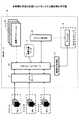
以下、図面に基づいて本発明の実施の形態を説明する。図1は、本発明の実施の形態におけるシステム構成例を示す図である。同図において、クライアント装置30a、30b、及び30cとWebサーバ10とはインターネット等のネットワークを介して接続されている。 Hereinafter, embodiments of the present invention will be described with reference to the drawings. FIG. 1 is a diagram showing an example of a system configuration in the embodiment of the present invention. In the figure,
Webサーバ10は、画面生成方法を実行するコンピュータ(画面生成装置)の具体例である。Webサーバ10は、画面遷移を伴うサービスをネットワークを介して提供する。具体的には、Webサーバ10は、インターネットを介してアプリケーションソフトウェア(以下、説明の便宜上単に「アプリケーション」という。)の機能によるサービスをテナント(後述する)に提供する。Webサーバ10によるサービスの提供形態としては、SaaS(Software as a Service)が一例として挙げられる。なお、Webサーバ10は、サービスの提供者によって管理されている。 The
クライアント装置30a、30b、及び30c等(以下、総称する場合「クライアント装置30」という。)は、サービス利用者側に属するコンピュータである。クライアント装置30a、クライアント装置30b、クライアント装置30cは、それぞれテナントA、テナントB、テナントCに属する。本実施の形態においてテナントとは、サービス提供者との間でサービスの利用契約を結んだ企業又は団体等の組織をいう。したがって、テナントは一人以上のユーザの集合であるといえる。 The
Webサーバ10は、HTTP(HyperText Transfer Protocol)サーバ11、アプリケーションサーバ12、拡張タグ処理部13、業務アプリケーション14、テナント判定部15、及び画面定義データ17等のソフトウェアを有する。 The
HTTPサーバ11は、クライアント装置30との通信を制御する。例えば、HTTPサーバ11は、クライアント装置30からの要求(HTTPリクエスト)を受信し、当該要求に対する応答(HTTPレスポンス)を返信する。 The HTTP server 11 controls communication with the client device 30. For example, the HTTP server 11 receives a request (HTTP request) from the client device 30 and returns a response (HTTP response) to the request.
アプリケーションサーバ12は、クライアント装置30からの要求に応じた(URL(Uniform Resource Locator)に対応した)業務アプリケーション14を起動させる(呼び出す)。アプリケーションサーバ12は、また、業務アプリケーション14による処理結果に応じ、クライアント装置30へ返信するための画面データ(HTMLデータ)を生成する。画面データは、画面定義データ17を利用して生成される。本実施の形態では、画面定義データ17としてJSP(Java(登録商標) Server Pages)データを適用した例を説明する。したがって、アプリケーションサーバ12は、JSPの実行環境であるJSPコンテナを含む。 The
拡張タグ処理部13は、画面定義データ17に記述されている拡張タグに対応した処理を実行する。すなわち、画面定義データ17は、本実施の形態において独自に定義された拡張タグを含む。 The extension
業務アプリケーション14は、いわゆるWebアプリケーションであり、機能に応じて複数存在する。本実施の形態において、各業務アプリケーション14は、複数のテナントより共通的に利用される。 The
テナント判定部15は、HTTPサーバ11によって受信されるHTTPリクエストに含まれている情報に基づいて当該HTTPリクエストの送信元のクライアント装置30(ユーザ)が属するテナントを判定する。テナント判定部15は、判定結果のテナントの識別情報(以下、「テナントID」という。)をセッションスコープ18に記録(登録)する。「セッションスコープ」とは、クライアント装置30とWebサーバ10とのセッション(又はセッション情報)を管理するためにメモリ装置103内に生成されるデータをいい、例えば、一般的にセッションオブジェクトと呼ばれる。テナントIDは、テナントごとに一意となるように割り当てられている。セッションスコープ18に記録されたテナントIDは、アプリケーションサーバ12が拡張タグ処理部13を利用してテナントごとにカスタマイズされた画面データを生成する際に参照される。なお、本実施の形態では、クライアント装置30とテナントIDとを関連付けて保持するための識別子記憶手段としてセッションスコープ18を用いる。但し、クライアント装置30との関連付けをセッションが接続されている間維持することが可能であれば、他のデータ(記憶領域)を識別子記憶手段として用いてもよい。また、セッションIDと同様にテナントIDをクッキー情報とし、HTTPリクエストのたびにクライアント装置30より送信されるようにしてもよい。 The
図2は、本発明の実施の形態におけるWebサーバのハードウェア構成例を示す図である。図2のWebサーバ10は、それぞれバスBで相互に接続されているドライブ装置100と、補助記憶装置102と、メモリ装置103と、CPU104と、インタフェース装置105とを有する。 FIG. 2 is a diagram illustrating a hardware configuration example of the Web server according to the embodiment of the present invention. The
Webサーバ10での処理を実現するプログラムは、CD−ROM等のコンピュータ読み取り可能な記録媒体101によって提供される。プログラムを記録した記録媒体101がドライブ装置100にセットされると、プログラムが記録媒体101からドライブ装置100を介して補助記憶装置102にインストールされる。但し、プログラムのインストールは必ずしも記録媒体101より行う必要はなく、ネットワークを介して他のコンピュータよりダウンロードするようにしてもよい。補助記憶装置102は、インストールされたプログラムを格納すると共に、必要なファイルやデータ(例えば、画面定義データ17)等を格納する。 A program for realizing processing in the
メモリ装置103は、プログラムの起動指示があった場合に、補助記憶装置102から読み出されたプログラムが格納される。CPU104は、メモリ装置103に格納されたプログラムに従ってWebサーバ10に係る機能を実行する。インタフェース装置105は、ネットワークに接続するためのインタフェースとして用いられる。 The
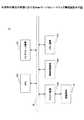
以下、Webサーバ10の処理手順について説明する。図3は、Webサーバによる処理手順を説明するためのフローチャートである。 Hereinafter, the processing procedure of the
HTTPサーバ11によるクライアント装置30aからのHTTPリクエストの受信に応じ(S101)、テナント判定部15は、クライアント装置30aとのセッションに対応するセッションスコープ18にテナントIDが登録されているか否かを判定する(S102)。 In response to reception of an HTTP request from the client device 30a by the HTTP server 11 (S101), the
なお、各セッションはセッションIDによって識別される。セッションIDは、セッションの開設時にアプリケーションサーバ12によって割り当てられ、クライアント装置30aに送信される。クライアント装置30aは、セッションIDをCookie(クッキー)等に保持しておき、HTTPリクエストの度にWebサーバ10に対して送信する。また、セッションスコープ18は、セッションの開設時にセッションIDと共にアプリケーションサーバ12によって生成され、セッションIDに関連付けられて管理されている。したがって、テナント判定部15は、セッションIDに基づいて現在のセッションに対応するセッションスコープ18を取得することができる。 Each session is identified by a session ID. The session ID is assigned by the
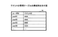
ところで、本実施の形態においてセッションスコープ18にテナントIDが登録されていないという状態は、受信されたHTTPリクエストがログイン要求である場合に相当する。ログイン要求には、クライアント装置10のWebブラウザに表示されているログイン画面に対して入力されたユーザID(各ユーザを識別するID)及びパスワードが含まれている。そこで、この場合(S102でNo)、テナント判定部15は、テナントID管理テーブルに基づいて、HTTPリクエスト(ログイン要求)に含まれているユーザIDに対応するテナントIDを判定する(S103)。 By the way, the state that the tenant ID is not registered in the
図4は、テナントID管理テーブルの構成例を示す図である。同図に示されるように、テナントID管理テーブル16には、ユーザIDとテナントIDとの対応情報が登録されている。例えば、ログイン要求に含まれているユーザIDが「user01」であった場合、テナント判定部15は、対応するテナントIDは「AAA」であると判定する。 FIG. 4 is a diagram illustrating a configuration example of the tenant ID management table. As shown in the figure, correspondence information between a user ID and a tenant ID is registered in the tenant ID management table 16. For example, when the user ID included in the login request is “user01”, the
続いて、テナント判定部15は、判定結果としてのテナントIDをセッションスコープ18に登録する(S104)。 Subsequently, the
なお、テナントにおける各ユーザがテナントIDを知っているという前提であれば、ログイン時等にテナントIDをユーザに入力させるようにしてもよい。この場合、クライアント装置30からのHTTPリクエストにはテナントIDが含まれている。したがって、HTTPリクエストに含まれているテナントIDをそのままセッションスコープ18に登録すればよい。 If it is assumed that each user in the tenant knows the tenant ID, the tenant ID may be input to the user at the time of login or the like. In this case, the tenant ID is included in the HTTP request from the client device 30. Therefore, the tenant ID included in the HTTP request may be registered in the
但し、本実施の形態のように、Webサーバ10においてユーザIDに基づいてテナントIDを自動的に判定することにより、テナントの各ユーザにテナントIDを周知させる必要をなくすことができる。また、各ユーザは、テナントIDを記憶したり、ログイン時にテナントIDを入力したりする必要はない。したがって、ユーザの作業負担を軽減することができる。 However, by automatically determining the tenant ID based on the user ID in the
一方、セッションスコープにテナントIDが既に登録されている場合(すなわち、HTTPリクエストがログイン要求以外の業務ロジックの実行要求の場合)(S102でYes)、ステップS103及びS104の処理は行われない。 On the other hand, when the tenant ID has already been registered in the session scope (that is, when the HTTP request is an execution request for business logic other than the login request) (Yes in S102), the processes in steps S103 and S104 are not performed.
続いて、アプリケーションサーバ12は、HTTPリクエストの内容(例えば、HTTPリクエストに含まれるURL等)に応じた業務アプリケーション14を判定し、当該業務アプリケーション14を呼び出す(又は起動する)(S105)。HTTPリクエストの内容に応じた業務アプリケーション14の判定は、例えば、補助記憶装置102に記録されている、URLと業務アプリケーション14との対応情報等に基づいて行えばよい。 Subsequently, the
続いて、呼び出された業務アプリケーション14は、自らに実装されている業務ロジックを実行する(S106)。業務ロジックの実行が完了すると、業務アプリケーション14は、実行結果に応じた画面データの生成をアプリケーションサーバ12に要求する。画面データの生成の要求の際、業務アプリケーション14は、画面データの生成に利用するJSPファイルのファイル名をアプリケーションサーバ12に指定する。 Subsequently, the called
続いて、アプリケーションサーバ12は、業務アプリケーション14に指定されたJSPファイルに基づいて画面データ(HTMLデータ)を生成する(S107)。アプリケーションサーバ12は、生成された画面データをHTTPサーバ11に出力する。続いて、HTTPサーバ11は、業務アプリケーション14によって生成された画面データをHTTPレスポンスに含めてクライアント装置30aに送信する(S108)。 Subsequently, the
図3の処理が繰り返し実行することにより、Webサーバ10がクライアント装置30aに提供する画面(すなわち、クライアント装置30aにおいて表示される画面)は、例えば、図5に示されるように遷移する。 By repeatedly executing the processing of FIG. 3, the screen provided by the
図5は、本実施の形態における画面遷移の例を示す図である。同図には、画面A、画面B、及び画面Cの順で画面が遷移することが示されている。すなわち、図3の処理が一回行われることにより、クライアント装置30aには画面Aが表示される。画面Aにおいて操作指示が入力されると、当該操作指示に応じて再度図3の処理が実行される。その結果、クライアント装置30aには画面Bが表示される。画面Bにおいて操作指示が入力されると、当該操作指示に応じて再度図3の処理が実行される。その結果、クライアント装置30aには画面Cが表示される。 FIG. 5 is a diagram illustrating an example of screen transition in the present embodiment. In the figure, it is shown that the screen transitions in the order of screen A, screen B, and screen C. That is, the screen A is displayed on the client device 30a by performing the process of FIG. 3 once. When an operation instruction is input on the screen A, the process of FIG. 3 is executed again according to the operation instruction. As a result, the screen B is displayed on the client device 30a. When an operation instruction is input on the screen B, the process of FIG. 3 is executed again according to the operation instruction. As a result, the screen C is displayed on the client device 30a.
なお、図3及び図5においては、クライアント装置30aを例として説明したが、クライアント装置30b及び30cにおいても同様の処理手順及び画面遷移が実行される。但し、本実施の形態では、画面A、画面B、及び画面Cのうちの少なくとも一部の画面をテナントごとにカスタマイズしたものを表示させることができる。テナントごとに固有の画面の表示を可能とするため、本実施の形態における画面定義データ17は、図6に示されるような構成を有する。 3 and 5, the client apparatus 30a has been described as an example. However, similar processing procedures and screen transitions are executed in the client apparatuses 30b and 30c. However, in the present embodiment, at least a part of the screen A, screen B, and screen C customized for each tenant can be displayed. In order to enable display of a unique screen for each tenant, the
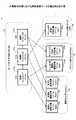
図6は、本実施の形態における画面定義データの構成例を示す図である。本実施の形態において、画面定義データ17は、JSPファイルの集合である。各JSPファイルは、その機能、役割、又は位置付けに応じたフォルダに分類されて保存されている。同図では、ルートフォルダ171、標準フォルダ172、テナントA用フォルダ173、テナントB用フォルダ174がJSPファイルの格納用のフォルダとして示されている。 FIG. 6 is a diagram illustrating a configuration example of the screen definition data in the present embodiment. In the present embodiment, the
ルートフォルダ171は、画面定義データ17の格納用のフォルダのルート(最上位)のフォルダである。ルートフォルダ171は、インクルードファイルとして機能するJSPファイルを格納する。本実施の形態においてインクルードファイルとは、拡張タグ処理部13を呼び出すための定義(拡張タグ)が記述されたJSPファイルをいう。拡張タグ処理部13は、セッションスコープ18に記録されているテナントIDに応じ、画面データの生成に用いる画面定義ファイルを標準フォルダ172又は各テナント用のフォルダ(テナントA用フォルダ173若しくはテナントB用フォルダ174)のいずれかより選択する。したがって、インクルードファイルは、テナントIDに応じて使用する画面定義ファイルを選択するための定義がなされたJSPファイルであると解釈することもできる。図中において、各インクルードファイルから各画面定義ファイルへの矢印は、斯かる選択関係を表現したものである。 The
インクルードファイルは、画面遷移における一連の画面ごとに生成される。したがって、同図では、画面Aに対応するインクルードファイル171a、画面Bに対応するインクルードファイル171b、画面Cに対応するインクルードファイル171cが示されている。なお、同図において、ルートフォルダのパス名は、「WEB−INF/jsp」とされている。また、各インクルードファイルのファイル名は、a.jsp、b.jsp、c.jspとされている。 The include file is generated for each series of screens in the screen transition. Therefore, in the figure, an include
図7は、インクルードファイルの定義例を示す図である。同図では、インクルードファイル171aの定義例が示されているが、インクルードファイル171b及び171cの定義内容も同様でよい。 FIG. 7 is a diagram illustrating a definition example of an include file. Although the definition example of the include
同図において、saas:includeタグ1712は、本実施の形態における拡張タグの具体例である。すなわち、saas:includeタグ1712は、拡張タグ処理部13を呼び出すための定義に相当する。 In the figure, a saas: include
記述1711は、JSP標準の定義であり、saas:includeタグ1712の処理を可能とするための定義がされている箇所を示す。すなわち、記述1711に含まれているURL「http://fx-saas.net/r3/tags-html」によって識別されるファイル内に、saas:includeタグと拡張タグ処理部13との対応情報が含まれている。本実施の形態において、拡張タグ処理部13は、Java(登録商標)のクラスとして実装されている。したがって、当該対応情報のより具体的な内容は、saas:includeタグと拡張タグ処理部13のクラス名との対応付けの定義である。 A
図6に戻る。標準フォルダ172は、Webサーバ10が標準で(デフォルトで)提供する画面を生成するための定義情報(画面定義データ)を格納したJSPファイル(画面定義ファイル)を格納するフォルダである。標準フォルダ172には、画面遷移に係る一連の画面ごとに標準の画面定義ファイルが保存されている。同図では、画面Aに対応する画面定義ファイル172a、画面Bに対応する画面定義ファイル172b、画面Cに対応する画面定義ファイル172cが示されている。なお、本実施の形態において、標準フォルダ172は、ルートフォルダ171の直下に「common」というフォルダ名で作成されている。したがって、標準フォルダのパス名は、「WEB−INF/jsp/common」となる。また、標準フォルダ172における各画面定義ファイルのファイル名は、a.jsp、b.jsp、c.jspとされている。すなわち、本実施の形態では、各画面定義ファイルのファイル名は、対応するインクルードファイルのファイル名と一致する。具体的には、画面定義ファイル172aのファイル名は「a.jsp」である。画面定義ファイル172bのファイル名は「b.jsp」である。画面定義ファイル172cのファイル名は「c.jsp」である。 Returning to FIG. The
テナントA用フォルダ173及びテナントB用フォルダ174は、それぞれ、テナントA用又はテナントB用に固有にカスタマイズされた画面定義ファイルを格納するフォルダである。但し、各テナント用フォルダには、必ずしも全ての画面に対する画面定義ファイルは格納されておらず、カスタマイズが必要な画面に対する画面定義ファイルのみが格納されている。例えば、テナントA用フォルダ173には、画面A用の画面定義ファイル173aと画面C用の画面定義ファイル173cとが格納されている。また、テナントB用フォルダ174には、画面B用の画面定義ファイル174bのみが格納されている。 The tenant A folder 173 and the
なお、本実施の形態においてテナントA用フォルダ173、テナントB用フォルダ174は、それぞれルートフォルダの直下に各テナントのテナントIDをフォルダ名として作成されている。したがって、テナントA用フォルダ173のパス名は、「WEB−INF/jsp/AAA」となる。また、テナントB用フォルダ174のパス名は、「WEB−INF/jsp/BBB」となる。また、各テナント用フォルダに格納されている画面定義ファイルのファイル名は、対応するインクルードファイルのファイル名と一致する。具体的には、画面定義ファイル173aのファイル名は「a.jsp」である。画面定義ファイル173cのファイル名は「c.jsp」である。画面定義ファイル174bのファイル名は「b.jsp」である。 In the present embodiment, the tenant A folder 173 and the
図8は、画面定義ファイルの定義例を示す図である。同図において、左側は標準の画面定義ファイル171aの定義例である。右側はテナントA用の画面定義ファイル172aである。具体的な定義内容については、標準のJSPの仕様に基づくためここでの説明は省略する。ここでは、二つの画面定義ファイルの相違点(図中破線で囲まれた記述1715と記述1725)に注目する。記述1715では、「計測項目検索・一覧画面」という文字列が<h2>タグによって囲まれている。一方、記述1725では、同一の文字列が<h1>タグによって囲まれている。すなわち、テナントA用の画面Aでは、「計測項目検索・一覧画面」という文字列のサイズが変更されている。 FIG. 8 is a diagram illustrating a definition example of the screen definition file. In the figure, the left side is a definition example of a standard
ところで、上記では、標準フォルダのフォルダ名は「common」であり、各画面定義ファイルのファイル名は、対応するインクルードファイルのファイル名と一致するといったように、それぞれ固定的に定められている。標準フォルダのフォルダ名や画面定義ファイルのファイル名に柔軟性を持たせるため、インクルードファイルを図9のように定義してもよい。 By the way, in the above, the folder name of the standard folder is “common”, and the file name of each screen definition file is fixedly determined so as to match the file name of the corresponding include file. In order to give flexibility to the folder name of the standard folder and the file name of the screen definition file, the include file may be defined as shown in FIG.
図9は、インクルードファイルの第二の定義例を示す図である。図9中、図7と対応する部分には同一符号を付し、その説明は適宜省略する。 FIG. 9 is a diagram illustrating a second definition example of the include file. 9, parts corresponding to those in FIG. 7 are denoted by the same reference numerals, and description thereof will be omitted as appropriate.
同図において、saas:includeタグは、defaultJsp属性1713及びjsp属性1714を含む。defaultJsp属性1713の値は、標準フォルダ172のフォルダ名(すなわち、標準フォルダ172の識別情報)を示す。jsp属性1714の値は、当該インクルードファイルに対応する画面定義ファイルのファイル名(すなわち、画面定義ファイルの識別情報)を示す。したがって、図9の定義例によれば、画面Aの標準の画面定義ファイルのパス名は、「WEB−INF/jsp/default/aaaaaa.jsp」とされる。また、画面AのテナントA用の画面定義ファイルのパス名は、「WEB−INF/jsp/AAA/aaaaaa.jsp」とされる。 In the drawing, the saas: include tag includes a
標準フォルダ172のフォルダ名や画面定義ファイルのファイル名を変更可能とすることで、標準フォルダ172のフォルダ構成や画面定義ファイルのファイル構成に柔軟性を持たせることが可能となる。なお、defaultJsp属性及びjsp属性は、インクルードファイルごと、すなわち、画面ごとに定義されうる。したがって、画面ごとに標準フォルダ171のパス名を変更したり、画面定義ファイルのファイル名を変更したりすることができる。 By making it possible to change the folder name of the
画面定義データ17に関して、図5〜図9において説明したことを前提とし、図3のステップS107の詳細について説明する。図10は、画面データ生成処理の処理手順を説明するためのフローチャートである。 The details of step S107 in FIG. 3 will be described on the assumption that the
ステップS201において、アプリケーションサーバ12は、業務アプリケーション14より指定されたJSPファイルを取得し、当該JSPファイルを実行する。ここで、実行対象とされるJSPファイルはインクルードファイルに相当する。例えば、遷移先の画面が画面Aである場合、業務アプリケーション14からは画面Aのファイル名(a.jsp)が指定される。アプリケーションサーバ12は、ルートフォルダ171内より当該ファイル名に係るJSPファイル(すなわち、インクルードファイル)を取得し、実行する。 In step S201, the
アプリケーションサーバ12は、インクルードファイルを1行ずつ実行していく過程において、saas:includeタグを検出すると(S202でYes)、拡張タグ処理部13を呼び出す。saas:includeタグの検出に応じて拡張タグ処理部13を呼び出すことは、例えば図7の記述1711に基づいて判定される。 When the
拡張タグ処理部13は、呼び出しに応じ、自らに実装された処理を実行する(S203)。拡張タグ処理部13による処理が完了すると、画面データ生成処理は完了する。 In response to the call, the extension
続いて、図10のステップS203の詳細について説明する。図11は、拡張タグ処理部による処理手順を説明するためのフローチャートである。 Next, details of step S203 in FIG. 10 will be described. FIG. 11 is a flowchart for explaining a processing procedure by the extension tag processing unit.
ステップS301において、拡張タグ処理部13は、処理対象となっているセッションのセッションスコープ18よりテナントIDを取得する。ここで、アプリケーションサーバ12、テナント判定部15、及び拡張タグ処理部13は同一スレッド内において動作する。したがって、拡張タグ処理部13は、アプリケーションサーバ12において当該スレッド空間内に生成され、テナント判定部15によってテナントIDが記録されたセッションスコープ18を参照すればよい。 In step S301, the extension
続いて、拡張タグ処理部13は、取得されたテナントIDを使用して、テナント用フォルダのパス名を生成する(S302)。本実施の形態において、テナント用フォルダのパス名は、ルートフォルダ171のパス名に対してテナントIDを付加したものである。したがって、例えば、テナントIDが「AAA」であれば、テナントA用フォルダ173のパス名は、「WEB−INF/jsp/AAA」として生成される。 Subsequently, the extension
続いて、拡張タグ処理部13は、saas:includeタグにjsp属性が指定されているか否かを確認する(S303)。jsp属性が指定されている場合(S303でYes)、拡張タグ処理部13は、テナント用フォルダのパス名にjsp属性の値を付加したものを処理対象の画面定義ファイルのパス名とする(S304)。具体的には、jsp属性の値が「aaaaaa.jsp」であれば、当該画面定義ファイルのパス名は、「WEB−INF/jsp/AAA/aaaaaa.jsp」とされる。 Subsequently, the extension
一方、jsp属性が指定されていない場合(S303でNo)、拡張タグ処理部13は、テナント用フォルダのパス名に、現在処理対象のインクルードファイルのファイル名を付加したものを処理対象の画面定義ファイルのパス名とする(S305)。具体的には、現在処理対象のインクルードファイルのファイル名が「a.jsp」であれば、当該画面定義ファイルのパス名は、「WEB−INF/jsp/AAA/a.jsp」とされる。 On the other hand, when the jsp attribute is not specified (No in S303), the extension
ステップS304又はS305に続いて、拡張タグ処理部13は、生成されたパス名に係る画面定義ファイルの存否を判定する(S306)。当該画面定義ファイルが存在する場合(すなわち、テナントIDに係るテナント用にカスタマイズされた画面定義ファイルが存在する場合)(S306でYes)、拡張タグ処理部13は、当該画面定義ファイルをアプリケーションサーバ12に実行させる(S307)。その結果、例えば、テナントA用フォルダ173内の画面定義ファイルが実行された場合、テナントA用にカスタマイズされた画面データが生成される。 Following step S304 or S305, the extension
一方、生成されたパス名に係る画面定義ファイルが存在しない場合(S306でNo)、拡張タグ処理部13は、saas:includeタグにdefaultJsp属性が指定されているか否かを確認する(S308)。defaultJsp属性が指定されている場合(S308でYes)、拡張タグ処理部13は、ルートフォルダのパス名にdefaultJsp属性の値を付加したものを遷移先の画面の標準フォルダ171のパス名とする(S309)。具体的には、defaultJsp属性の値が「default」であれば標準フォルダ171のパス名は、「WEB−INF/jsp/default」とされる。 On the other hand, when the screen definition file relating to the generated path name does not exist (No in S306), the extension
また、defaultJsp属性が指定されていない場合(S308でNo)、拡張タグ処理部13は、ルートフォルダのパス名に予め定められているフォルダ名(common)を付加したものを遷移先の画面の標準フォルダ171のパス名とする(S310)。したがって、標準フォルダ171のパス名は「WEB−INF/jsp/common」とされる。 If the defaultJsp attribute is not specified (No in S308), the extension
ステップS308又はS309に続いて、拡張タグ処理部13は、標準フォルダ171のパス名に画面定義ファイルのファイル名を付加し、標準の画面定義ファイルのパス名を生成する(S311)。ここで付加される画面定義ファイルのファイル名は、ステップS303〜S305において判定されたものに従う。すなわち、インクルードファイルにjsp属性が指定されていればjsp属性の値が採用される。jsp属性が指定されていなければ、インクルードファイルのファイル名が採用される。 Subsequent to step S308 or S309, the extension
続いて、拡張タグ処理部13は、生成されたパス名に係る画面定義ファイルをアプリケーションサーバ12に実行させる(S312)。その結果、標準の画面定義ファイルに基づいて標準の画面データが生成される。 Subsequently, the extension
上述したように、本実施の形態によれば、画面遷移に係る一連の画面を生成する際に、テナント固有にカスタマイズされた画面定義ファイルが存在する場合は当該固有の画面定義ファイルが利用される。また、テナント固有にカスタマイズ画面定義ファイルが存在しない場合は、標準の(全てのテナントに対して共通の)画面定義ファイルが利用される。 As described above, according to the present embodiment, when a screen definition file customized for a tenant exists when a series of screens related to screen transition is generated, the specific screen definition file is used. . If there is no customization screen definition file specific to a tenant, the standard screen definition file (common to all tenants) is used.
例えば、図6のように画面定義ファイルが作成されている場合、テナントAについては、画面Bは標準の画面が表示される。テナントBについては、画面A及びCは標準の画面が表示される。また、テナントCについては、固有の画面定義ファイルを作成されていないため、全ての画面について標準の画面が表示される。 For example, when a screen definition file is created as shown in FIG. 6, a standard screen is displayed as the screen B for the tenant A. For tenant B, screens A and C are displayed as standard screens. For tenant C, a unique screen definition file has not been created, so standard screens are displayed for all screens.
したがって、画面遷移に係る全ての画面について画面定義ファイルを作成する必要はない。換言すれば、カスタマイズが必要な一部の画面について画面定義ファイルを作成すればよい。その結果、全ての画面について画面定義ファイルを作成する場合に比べ、画面定義ファイルのファイル数を削減することができる。よって、画面定義ファイルを作成するための工数や、画面定義ファイルを保存するための記憶容量等を削減することができる。 Therefore, it is not necessary to create screen definition files for all screens related to screen transition. In other words, a screen definition file may be created for some screens that need to be customized. As a result, the number of screen definition files can be reduced compared to the case where screen definition files are created for all screens. Therefore, the man-hours for creating the screen definition file, the storage capacity for saving the screen definition file, and the like can be reduced.
なお、カスタマイズの単位をテナントごとではなく、ユーザ(ここで、ユーザは一個人を意味する。)ごとにする必要がある場合、テナントIDをユーザIDに置き換えて本実施の形態を実施すればよい。具体的には、セッションスコープ18にはユーザIDを記録すればよい。また、ユーザIDに応じて画面定義ファイルを作成しておけばよい。この場合、クライアント識別子の具体例は、テナントIDではなく、ユーザIDとなる。 Note that if the customization unit needs to be for each user (here, the user means one individual) instead of for each tenant, the tenant ID may be replaced with the user ID and the present embodiment may be implemented. Specifically, the user ID may be recorded in the
また、画面定義データとして、JSP以外のデータを用いてもよい。例えば、XML(eXtensible Markup Language)データやXSL(eXtensible Stylesheet Language)データを用いてもよい。また、ASP(Active Server Pages)を用いてもよい。その他のデータ形式や、独自に定義したデータを用いてもよい。 Further, data other than JSP may be used as the screen definition data. For example, XML (eXtensible Markup Language) data or XSL (eXtensible Stylesheet Language) data may be used. Further, ASP (Active Server Pages) may be used. Other data formats or uniquely defined data may be used.
また、本実施の形態では、標準の画面定義ファイルとテナントごとに固有の画面定義ファイルとを保存先のフォルダを変えることによって区別していたが、例えば、ファイル名によって区別するようにしてもよい。例えば、テナントごとに固有の画面定義ファイルには、テナントIDがファイル名に含まれるようにしてもよい。この場合、標準の画面定義ファイル及び各テナント用の画面定義ファイルは、同じフォルダ内に保存されていてもよい。 Further, in the present embodiment, the standard screen definition file and the screen definition file unique to each tenant are distinguished by changing the storage folder, but for example, they may be distinguished by a file name. . For example, the tenant ID may be included in the file name in the screen definition file unique to each tenant. In this case, the standard screen definition file and the screen definition file for each tenant may be stored in the same folder.
ところで、本実施の形態によれば、テナントごとに画面のカスタマイズが不可能であった(すなわち、全てのテナントに標準の画面が提供される)既存のシステムからの移行コストを低減できるというメリットもある。全てのテナントに標準の画面が提供されるシステムにおける画面定義データは、一般的に図12のように構成される。 By the way, according to the present embodiment, it is not possible to customize the screen for each tenant (that is, a standard screen is provided for all tenants). is there. Screen definition data in a system in which standard screens are provided to all tenants is generally configured as shown in FIG.
図12は、全てのテナントに標準の画面が提供されるシステムにおける画面定義データの構成例を示す図である。図12中、図6と対応する部分には同一符号を付している。 FIG. 12 is a diagram illustrating a configuration example of screen definition data in a system in which a standard screen is provided to all tenants. In FIG. 12, parts corresponding to those in FIG.
図12に示されるように、全てのテナントに標準の画面が提供されるシステムでは、ルートフォルダ171内に、標準の画面定義データ171a、171b、及び171cが保存されている。この状態から、図6の状態へ移行するためには、インクルードファイルの生成、標準の画面定義データの保存場所の移動、カスタマイズが必要なテナントに対する画面定義データの作成、及び拡張タグ処理部13の実装を行えばよい。したがって、既存のプログラムのコーディングを変更したりする必要はない。よって、比較的簡便な作業によって、テナントごとにカスタマイズされた画面を提供可能なシステムに移行することができる。 As shown in FIG. 12, in a system in which standard screens are provided to all tenants, standard
以上、本発明の実施例について詳述したが、本発明は斯かる特定の実施形態に限定されるものではなく、特許請求の範囲に記載された本発明の要旨の範囲内において、種々の変形・変更が可能である。 As mentioned above, although the Example of this invention was explained in full detail, this invention is not limited to such specific embodiment, In the range of the summary of this invention described in the claim, various deformation | transformation・ Change is possible.
10 HTTPサーバ
11 HTTPサーバ
12 アプリケーションサーバ
13 拡張タグ処理部
14 業務アプリケーション
15 テナント判定部
17 画面定義データ
18 セッションスコープ
100 ドライブ装置
101 記録媒体
102 補助記憶装置
103 メモリ装置
104 CPU
105 インタフェース装置
B バス10 HTTP server 11
105 Interface device B bus
Claims (4)
Translated fromJapanese端末装置からの操作入力に基づく複数の画面遷移それぞれにおいて、遷移先画面が該端末装置が属するテナントについて前記複数のテナントで共用される定義情報に基づく画面であり、前記共用される定義情報に基づいて前記遷移先画面の画面データを生成した後に、該端末装置についての次の遷移先画面が前記ある端末装置の属するテナントに対応付けられた、前記共用される定義情報と異なる定義情報に基づく画面であるときは、前記異なる定義情報に基づいて前記次の遷移先画面の画面データを生成する、
ことを特徴とする画面生成方法。A computer that generates screen data
A plurality of screen transition, respectively based on the operation input from the terminal device,Ri screen der based on the definition information destination screen is shared bythe plurality of tenants Tenantswhich the terminal apparatus belongs, the definition information is the common basedafter generatingthe screen data ofthe transition target screen, thenext transition destination screen associated with the tenant belongs terminal device locatedabove the terminal device, the definition information different definition information shared When the screen is based on, the screen data of thenext transition destination screen is generated based on the different definition information.
A screen generation method characterized by that.
送信した該ユーザ識別情報に基づいて前記画面生成装置によって判定されたテナントについて、前記端末装置についての遷移先画面が前記複数のテナントで共用される定義情報に基づく画面であるときは、前記共用される定義情報に基づいて生成された画面データを遷移先画面データとして受信し、送信した該ユーザ識別情報に基づいて前記画面生成装置によって判定されたテナントについて、前記端末装置についての遷移先画面が当該テナントに対応付けられた、前記共用される定義情報と異なる定義情報に基づく画面であるときは、前記異なる定義情報に基づいて生成された画面データを遷移先画面データとして受信し、
受信した画面データを遷移先の画面データとして前記端末装置の表示部にそれぞれ表示する、
ことを特徴とする画面表示を行う画面表示方法。A definition information shared by a plurality of tenants in the definition information to each plurality of screen transition based on the operation input from the terminal devicebelonging to the tenant that both associated with a different definition information, destination screen isthe when the tenant to which the terminal belongs is a screen based on the definition information is shared bythe plurality of tenants, the generated screen data of the transition destination screen on the basis of the definition information are shared, the transition destination screen isthe terminal device When the screen is based on definition information different from the shared definition information associated with the tenant to which the user belongs, the screen generation device that generates screen data of the transition destination screen based on the different definition information, Send user identification information that can identify which tenant it belongs to,
Tenants it is determined by the screen generating apparatus based on the transmitted the user identification information, when the destination screenon the terminal device is a screen based on the definition information is shared bythe plurality of tenant is the shared Screen data generated based on the definition information is received as transition destination screen data, and the transition destination screen for theterminal device is the tenant determined by the screen generation device based on the transmitted user identification information. When the screen is based on definition information different from the shared definition information associated with the tenant, screen data generated based on the different definition information is received as transition destination screen data,
Respectively displayed on the display unitof the terminal device the received screen data as the transition destination screen data,
A screen display method for performing screen display characterized by this.
ことを特徴とする画面生成装置。A plurality of screen transition, respectively based on the operation input from the terminal device,Ri screen der based on the definition information destination screen is shared bythe plurality of tenants Tenantswhich the terminal apparatus belongs, the definition information is the common basedafter generatingthe screen data ofthe transition target screen, thenext transition destination screen associated with the tenant belongs terminal device locatedabove the terminal device, the definition information different definition information shared When the screen is based on, the screen data of thenext transition destination screen is generated based on the different definition information.
A screen generation device characterized by that.
端末装置からの操作入力に基づく複数の画面遷移それぞれにおいて、遷移先画面が該端末装置が属するテナントについて前記複数のテナントで共用される定義情報に基づく画面であり、前記共用される定義情報に基づいて前記遷移先画面の画面データを生成した後に、該端末装置についての次の遷移先画面が前記ある端末装置の属するテナントに対応付けられた、前記共用される定義情報と異なる定義情報に基づく画面であるときは、前記異なる定義情報に基づいて前記次の遷移先画面の画面データを生成する、
処理を実行させることを特徴とするプログラム。On the computer that generates the screen data,
A plurality of screen transition, respectively based on the operation input from the terminal device,Ri screen der based on the definition information destination screen is shared bythe plurality of tenants Tenantswhich the terminal apparatus belongs, the definition information is the common basedafter generatingthe screen data ofthe transition target screen, thenext transition destination screen associated with the tenant belongs terminal device locatedabove the terminal device, the definition information different definition information shared When the screen is based on, the screen data of thenext transition destination screen is generated based on the different definition information.
A program characterized by causing processing to be executed.
Priority Applications (3)
| Application Number | Priority Date | Filing Date | Title |
|---|---|---|---|
| JP2009029021AJP5638761B2 (en) | 2009-02-10 | 2009-02-10 | Screen generation method, screen display method, screen generation device, and program |
| US12/618,160US9223896B2 (en) | 2009-02-10 | 2009-11-13 | Screen generation method, and screen generation apparatus |
| EP09176681AEP2216723A3 (en) | 2009-02-10 | 2009-11-20 | Screen generation method, and screen generation apparatus |
Applications Claiming Priority (1)
| Application Number | Priority Date | Filing Date | Title |
|---|---|---|---|
| JP2009029021AJP5638761B2 (en) | 2009-02-10 | 2009-02-10 | Screen generation method, screen display method, screen generation device, and program |
Publications (2)
| Publication Number | Publication Date |
|---|---|
| JP2010186264A JP2010186264A (en) | 2010-08-26 |
| JP5638761B2true JP5638761B2 (en) | 2014-12-10 |
Family
ID=42235472
Family Applications (1)
| Application Number | Title | Priority Date | Filing Date |
|---|---|---|---|
| JP2009029021AExpired - Fee RelatedJP5638761B2 (en) | 2009-02-10 | 2009-02-10 | Screen generation method, screen display method, screen generation device, and program |
Country Status (3)
| Country | Link |
|---|---|
| US (1) | US9223896B2 (en) |
| EP (1) | EP2216723A3 (en) |
| JP (1) | JP5638761B2 (en) |
Families Citing this family (8)
| Publication number | Priority date | Publication date | Assignee | Title |
|---|---|---|---|---|
| US20100174992A1 (en)* | 2009-01-04 | 2010-07-08 | Leon Portman | System and method for screen recording |
| US9715555B2 (en)* | 2010-02-26 | 2017-07-25 | Salesforce.Com, Inc. | System, method and computer program product for user registration with a multi-tenant on-demand database system |
| US8566923B2 (en)* | 2011-02-01 | 2013-10-22 | Rockwell Automation Technologies, Inc. | Enhanced organization and automatic navigation of display screens facilitating automation control |
| JP5882623B2 (en)* | 2011-08-03 | 2016-03-09 | キヤノン株式会社 | Information processing apparatus, control method, and program |
| US9826027B2 (en)* | 2014-08-19 | 2017-11-21 | Bank Of America Corporation | User interfaces generated by a workflow engine |
| JP6375877B2 (en) | 2014-10-31 | 2018-08-22 | 株式会社リコー | Information processing system, information processing method, service utilization apparatus, and program |
| JP6492642B2 (en)* | 2014-12-25 | 2019-04-03 | ブラザー工業株式会社 | Image forming apparatus, image forming system, and program |
| US10645173B2 (en)* | 2017-10-30 | 2020-05-05 | International Business Machines Corporation | Session handling for multi-user multi-tenant web applications |
Family Cites Families (24)
| Publication number | Priority date | Publication date | Assignee | Title |
|---|---|---|---|---|
| JP3535267B2 (en)* | 1995-07-03 | 2004-06-07 | 富士通株式会社 | Monitoring system display device for monitoring system |
| US5999179A (en)* | 1997-11-17 | 1999-12-07 | Fujitsu Limited | Platform independent computer network management client |
| US6697088B1 (en)* | 1998-04-27 | 2004-02-24 | Jacada, Inc. | Graphical presentation system |
| US6263346B1 (en)* | 1998-07-17 | 2001-07-17 | International Business Machines Corporation | Network with storage of all client computer programs in server computer having customized client graphical user interfaces with maximum sharing of stored portions of interfaces common to a plurality of clients |
| US6505246B1 (en)* | 1998-12-30 | 2003-01-07 | Candle Distributed Solutions, Inc. | User interface for system management applications |
| EP1103899A3 (en)* | 1999-11-29 | 2001-08-29 | Citicorp Development Center, Inc. | A method and system for generating display screen templates |
| US6954751B2 (en)* | 2000-09-06 | 2005-10-11 | Oracle International Corporation | Accessing data stored at an intermediary from a service |
| EP1205843A3 (en)* | 2000-11-13 | 2004-10-20 | Canon Kabushiki Kaisha | User interfaces |
| JP2002163382A (en)* | 2000-11-29 | 2002-06-07 | Fujitsu Ltd | Customization method for ASP service |
| EP1220507A1 (en)* | 2000-12-22 | 2002-07-03 | Sun Microsystems, Inc. | Creating web content in a client and server system |
| GB0108354D0 (en)* | 2001-04-03 | 2001-05-23 | Thirdspace Living Ltd | System and method for providing a user with access to a plurality of sevices and content from a broadband television service |
| US7038588B2 (en)* | 2001-05-04 | 2006-05-02 | Draeger Medical Infant Care, Inc. | Apparatus and method for patient point-of-care data management |
| JP2003044417A (en)* | 2001-07-30 | 2003-02-14 | Kernel:Kk | Client-server system structuring method equipped with managing function and interactive function |
| US8112493B2 (en)* | 2004-01-16 | 2012-02-07 | International Business Machines Corporation | Programmatic role-based security for a dynamically generated user interface |
| JP2005266946A (en)* | 2004-03-16 | 2005-09-29 | Ricoh Co Ltd | Information processing apparatus, information processing method, information processing program, and recording medium |
| CN1942854B (en)* | 2004-04-05 | 2010-05-12 | 松下电器产业株式会社 | Screen transition control device and method |
| JP2006031666A (en)* | 2004-06-17 | 2006-02-02 | Epson Avasys Corp | Electronic document browsing system |
| JP2007282199A (en)* | 2006-03-15 | 2007-10-25 | Ricoh Co Ltd | Flow mounting system, flow mounting method, flow mounting program, and image processing apparatus |
| JP2007279974A (en)* | 2006-04-05 | 2007-10-25 | Ricoh Co Ltd | Display screen control device, electronic device, display screen control system, display screen control method, screen display method, display screen control program, and screen display program |
| US8972534B2 (en)* | 2006-04-12 | 2015-03-03 | International Business Machines Corporation | Adjusting software settings |
| JP2007316904A (en)* | 2006-05-25 | 2007-12-06 | Ricoh Co Ltd | Web application system, Web application screen providing method, and program thereof |
| JPWO2008075492A1 (en)* | 2006-12-19 | 2010-04-08 | 三菱電機株式会社 | Map display device |
| CN101334865A (en)* | 2007-06-28 | 2008-12-31 | 国际商业机器公司 | Working stream user interface creation method and creator |
| US20110010394A1 (en)* | 2009-07-08 | 2011-01-13 | International Business Machines Corporation | Client-specific data customization for shared databases |
- 2009
- 2009-02-10JPJP2009029021Apatent/JP5638761B2/ennot_activeExpired - Fee Related
- 2009-11-13USUS12/618,160patent/US9223896B2/ennot_activeExpired - Fee Related
- 2009-11-20EPEP09176681Apatent/EP2216723A3/ennot_activeCeased
Also Published As
| Publication number | Publication date |
|---|---|
| JP2010186264A (en) | 2010-08-26 |
| EP2216723A2 (en) | 2010-08-11 |
| EP2216723A3 (en) | 2011-01-12 |
| US9223896B2 (en) | 2015-12-29 |
| US20110083083A1 (en) | 2011-04-07 |
Similar Documents
| Publication | Publication Date | Title |
|---|---|---|
| JP5638761B2 (en) | Screen generation method, screen display method, screen generation device, and program | |
| JP4902671B2 (en) | Strategies for sending content to target devices | |
| US8332520B2 (en) | Web server for managing session and method thereof | |
| KR101505234B1 (en) | Xml-based web feed for web access of remote resources | |
| JP2004318842A (en) | Web page generation device, embedded device, Web page generation control method, Web page generation program, and recording medium | |
| JP2015125620A (en) | Information processing apparatus, control method therefor, program, and information processing system | |
| RU2628210C2 (en) | Activation of service functions in working applications | |
| JP2004303218A (en) | Information providing device and information display device | |
| JP2015518612A (en) | Computer system, non-transitory computer readable storage medium and method enabling styling and decoration of multiple and dissimilar web pages by remote method invocation | |
| CN102004729A (en) | Method and system for showing website webpage and website server | |
| US9769246B2 (en) | Information processing terminal and control method | |
| JP2011186768A (en) | File management system, information processor, and information processing method | |
| JP4881485B1 (en) | Information notification system, information presentation system, information notification method, information presentation method, information notification program, and information presentation program | |
| WO2015097729A1 (en) | Information processing device, web server and computer program | |
| JP2006244430A (en) | Information distribution management device | |
| JP2017049966A (en) | Information processing apparatus, control method thereof, and program | |
| JP2004326740A (en) | Web page generation device, embedded device, Web page generation system, Web page generation control method, Web page generation program, and recording medium | |
| JP2007272444A (en) | Content management apparatus, content management method, and content management program | |
| JP6128503B1 (en) | Program, server and system for providing services related to electronic manuals | |
| JP4204493B2 (en) | Data relay program | |
| JP4208185B2 (en) | Method and apparatus for converting existing web application to web service | |
| JP2007087221A (en) | Shopping mall system | |
| JP4710408B2 (en) | Method for providing content, information providing system, and information providing program | |
| JP2017175414A (en) | Image processing server, data transmission program, and distribution device | |
| JP6341013B2 (en) | Terminal device, communication system, and program |
Legal Events
| Date | Code | Title | Description |
|---|---|---|---|
| A621 | Written request for application examination | Free format text:JAPANESE INTERMEDIATE CODE: A621 Effective date:20111006 | |
| A977 | Report on retrieval | Free format text:JAPANESE INTERMEDIATE CODE: A971007 Effective date:20120808 | |
| A131 | Notification of reasons for refusal | Free format text:JAPANESE INTERMEDIATE CODE: A131 Effective date:20120814 | |
| A521 | Request for written amendment filed | Free format text:JAPANESE INTERMEDIATE CODE: A523 Effective date:20121015 | |
| A131 | Notification of reasons for refusal | Free format text:JAPANESE INTERMEDIATE CODE: A131 Effective date:20130423 | |
| A521 | Request for written amendment filed | Free format text:JAPANESE INTERMEDIATE CODE: A523 Effective date:20130624 | |
| A02 | Decision of refusal | Free format text:JAPANESE INTERMEDIATE CODE: A02 Effective date:20130723 | |
| A521 | Request for written amendment filed | Free format text:JAPANESE INTERMEDIATE CODE: A523 Effective date:20131023 | |
| A911 | Transfer to examiner for re-examination before appeal (zenchi) | Free format text:JAPANESE INTERMEDIATE CODE: A911 Effective date:20131030 | |
| A912 | Re-examination (zenchi) completed and case transferred to appeal board | Free format text:JAPANESE INTERMEDIATE CODE: A912 Effective date:20131220 | |
| A61 | First payment of annual fees (during grant procedure) | Free format text:JAPANESE INTERMEDIATE CODE: A61 Effective date:20141023 | |
| R150 | Certificate of patent or registration of utility model | Ref document number:5638761 Country of ref document:JP Free format text:JAPANESE INTERMEDIATE CODE: R150 | |
| LAPS | Cancellation because of no payment of annual fees |