JP5638306B2 - Oil strainer - Google Patents
Oil strainerDownload PDFInfo
- Publication number
- JP5638306B2 JP5638306B2JP2010172470AJP2010172470AJP5638306B2JP 5638306 B2JP5638306 B2JP 5638306B2JP 2010172470 AJP2010172470 AJP 2010172470AJP 2010172470 AJP2010172470 AJP 2010172470AJP 5638306 B2JP5638306 B2JP 5638306B2
- Authority
- JP
- Japan
- Prior art keywords
- wall portion
- divided body
- oil
- wall
- portions
- Prior art date
- Legal status (The legal status is an assumption and is not a legal conclusion. Google has not performed a legal analysis and makes no representation as to the accuracy of the status listed.)
- Expired - Fee Related
Links
- 230000002093peripheral effectEffects0.000claimsdescription83
- 238000003780insertionMethods0.000claimsdescription28
- 230000037431insertionEffects0.000claimsdescription28
- 230000013011matingEffects0.000claimsdescription9
- 238000001914filtrationMethods0.000claimsdescription3
- 239000003921oilSubstances0.000description231
- 210000000078clawAnatomy0.000description37
- 238000007789sealingMethods0.000description15
- 239000011347resinSubstances0.000description9
- 229920005989resinPolymers0.000description9
- 239000000463materialSubstances0.000description8
- 230000005540biological transmissionEffects0.000description7
- 230000000694effectsEffects0.000description5
- 238000001746injection mouldingMethods0.000description5
- 239000002184metalSubstances0.000description5
- 239000007788liquidSubstances0.000description4
- 239000007769metal materialSubstances0.000description4
- 238000000465mouldingMethods0.000description4
- 238000013459approachMethods0.000description3
- 238000005452bendingMethods0.000description3
- 238000012986modificationMethods0.000description3
- 230000004048modificationEffects0.000description3
- 239000010705motor oilSubstances0.000description3
- 238000011144upstream manufacturingMethods0.000description3
- 238000002485combustion reactionMethods0.000description2
- 230000000994depressogenic effectEffects0.000description2
- 238000005461lubricationMethods0.000description2
- 230000003014reinforcing effectEffects0.000description2
- 230000000630rising effectEffects0.000description2
- 230000000740bleeding effectEffects0.000description1
- 239000000470constituentSubstances0.000description1
- 238000000034methodMethods0.000description1
- 239000003566sealing materialSubstances0.000description1
- 238000013022ventingMethods0.000description1
- 238000003466weldingMethods0.000description1
Images


Landscapes
- Lubrication Details And Ventilation Of Internal Combustion Engines (AREA)
Description
Translated fromJapanese本発明は、例えば、自動車の内燃機関等に設けられ、該内燃機関内を循環するオイルを濾過するオイルストレーナに関するものである。 The present invention relates to an oil strainer that is provided, for example, in an internal combustion engine of an automobile and filters oil circulating in the internal combustion engine.
従来より、この種のオイルストレーナとして、例えば上下方向に2つに分割した上側分割体と下側分割体とを組み合わせることで、内部にオイル流入空間を形成するように構成されたものが知られている(例えば、特許文献1参照)。 Conventionally, as this kind of oil strainer, for example, an oil strainer configured to form an oil inflow space by combining an upper divided body and a lower divided body divided into two in the vertical direction is known. (For example, refer to Patent Document 1).
この特許文献1のオイルストレーナの下側分割体は、オイルを濾過してオイル流入空間に流入させるフィルタ部と、このフィルタ部の外周部から上側分割体側へ延びるように形成された環状の第1壁部とを備えている。上側分割体は、オイル流入空間に流入したオイルを流出させるオイル流出部と、このオイル流出部に連なり第1壁部の内面又は外面に対応する箇所まで延びる第2壁部とを備えている。第1壁部における第2壁部側の面には、該第1壁部に沿う環状の係合部が形成され、第2壁部における第1壁部側の面には、係合部に係合する環状の被係合部が形成され、係合部と被係合部とが係合して上側分割体と下側分割体とが一体化されている。 The lower divided body of the oil strainer of
これにより、溶着法を用いることなく両分割体の合わせ部のシール性を確保できるようになり、オイルの吸い上げ不良及び濾過されてないオイルが吸い込まれてしまうのを抑制され、潤滑性能を確保できる。 As a result, it becomes possible to ensure the sealing performance of the mating portion of both divided bodies without using a welding method, and it is possible to prevent poor suction of oil and suction of unfiltered oil, thereby ensuring lubrication performance. .
しかしながら、上記特許文献1のオイルトレーナでは、係合部及び被係合部の係合による1段階のシール構造により、上側分割体と下側分割体との間のシール性を確保しているので、両分割体の間のシール性が低下してしまう虞れがある。両分割体の間のシール性が低下してしまうと、両分割体の合わせ部からエアーを吸い込んでオイルの吸い上げ不良が発生するとともに、濾過されていないオイルがオイル流入空間に吸い込まれることになり、潤滑性能が悪化してしまう。 However, in the oil trainer disclosed in
また、特許文献1のオイルトレーナでは、経時変化に起因して係合部と被係合部との係合状態が弱くなると、フィルタ部が脱落してしまう虞れがある。 Further, in the oil trainer disclosed in
本発明は、かかる点に鑑みてなされたものであり、その課題とするところは、第1分割体と第2分割体とがオイル流入空間を形成するように組み合わされてなるオイルストレーナにおいて、簡単な構造で、第1分割体と第2分割体との間のシール性を向上させるとともに、フィルタ部が脱落することを抑制することにある。 The present invention has been made in view of such a point, and the problem is that an oil strainer in which the first divided body and the second divided body are combined so as to form an oil inflow space. With a simple structure, the sealing performance between the first divided body and the second divided body is improved, and the filter unit is prevented from falling off.
第1の発明は、第1分割体と第2分割体とがオイル流入空間を形成するように組み合わされてなるオイルストレーナであって、上記第1分割体には、オイルを濾過して上記オイル流入空間に流入させるフィルタ部が設けられており、上記第2分割体には、上記オイル流入空間に流入したオイルを流出させるオイル流出部が設けられており、上記第1及び第2分割体の合わせ部の一方には、内側壁部と、該内側壁部との間に嵌入溝部を形成する外側壁部とが全周に亘って形成されており、他方には、該嵌入溝部に嵌入する嵌入壁部が全周に亘って形成されており、上記外側壁部には、係合部が形成されており、上記嵌入壁部には、該係合部に係合する被係合部が形成されており、上記第1及び第2分割体の分割方向は、上下方向であり、上記第1分割体は、上記第2分割体の下方に配置されていて、上記フィルタ部が設けられた底壁部と、該底壁部の外周部に全周に亘って形成された周壁部とを備えており、上記第2分割体は、上記オイル流出部が設けられた頂壁部と、該頂壁部の外周部に全周に亘って形成された周壁部とを備えており、上記第1及び第2分割体の周壁部の一方には、上記内側及び外側壁部が形成されており、他方には、上記嵌入壁部が形成されており、上記第2分割体の頂壁部の長手方向端部には、エアー抜き用の開口部が形成されていることを特徴とするものである。 A first invention is an oil strainer in which a first divided body and a second divided body are combined so as to form an oil inflow space, and the oil is filtered into the first divided body. A filter portion that flows into the inflow space is provided, and the second divided body is provided with an oil outflow portion that flows out the oil that has flowed into the oil inflow space. One of the mating portions is formed with an inner wall portion and an outer wall portion that forms a fitting groove portion between the inner wall portion and the other portion, and the other portion is fitted into the fitting groove portion. An insertion wall portion is formed over the entire circumference, an engagement portion is formed on the outer wall portion, and an engaged portion that engages with the engagement portion is formed on the insertion wall portion. The dividing direction of the first and second divided bodies is a vertical direction, and the first The divided body is disposed below the second divided body, and includes a bottom wall portion provided with the filter portion, and a peripheral wall portion formed on the entire outer periphery of the bottom wall portion. The second divided body includes a top wall portion provided with the oil outflow portion, and a peripheral wall portion formed over the entire outer periphery of the top wall portion. The inner and outer wall portions are formed on one of the peripheral wall portions of the second divided body, and the fitting wall portion is formed on the other, and the longitudinal length of the top wall portion of the second divided body is An opening for air bleeding is formed at the end of the direction.
第2の発明は、第1分割体と第2分割体とがオイル流入空間を形成するように組み合わされてなるオイルストレーナであって、上記第1分割体には、オイルを濾過して上記オイル流入空間に流入させるフィルタ部が設けられており、上記第2分割体には、上記オイル流入空間に流入したオイルを流出させるオイル流出部が設けられており、上記第1及び第2分割体の合わせ部の一方には、内側壁部と、該内側壁部との間に嵌入溝部を形成する外側壁部とが全周に亘って形成されており、他方には、該嵌入溝部に嵌入する嵌入壁部が全周に亘って形成されており、上記外側壁部には、係合部が形成されており、上記嵌入壁部には、該係合部に係合する被係合部が形成されており、上記第1及び第2分割体の分割方向は、上下方向であり、上記第1分割体は、上記第2分割体の下方に配置されていて、上記フィルタ部が設けられた底壁部と、該底壁部の外周部に全周に亘って形成された周壁部とを備えており、上記第2分割体は、上記オイル流出部が設けられた頂壁部と、該頂壁部の外周部に全周に亘って形成された周壁部とを備えており、上記第2分割体の周壁部には、上記内側及び外側壁部が形成されており、上記第1分割体の周壁部には、上記嵌入壁部が形成されており、上記内側及び外側壁部は、周方向の少なくとも一部が上記第2分割体の頂壁部よりも上方に突出していることを特徴とするものである。 A second invention is an oil strainer in which a first divided body and a second divided body are combined so as to form an oil inflow space, and the oil is filtered through the first divided body. A filter portion that flows into the inflow space is provided, and the second divided body is provided with an oil outflow portion that flows out the oil that has flowed into the oil inflow space. One of the mating portions is formed with an inner wall portion and an outer wall portion that forms a fitting groove portion between the inner wall portion and the other portion, and the other portion is fitted into the fitting groove portion. An insertion wall portion is formed over the entire circumference, an engagement portion is formed on the outer wall portion, and an engaged portion that engages with the engagement portion is formed on the insertion wall portion. The dividing direction of the first and second divided bodies is a vertical direction, and the first The divided body is disposed below the second divided body, and includes a bottom wall portion provided with the filter portion, and a peripheral wall portion formed on the entire outer periphery of the bottom wall portion. The second divided body includes a top wall portion provided with the oil outflow portion, and a peripheral wall portion formed over the entire outer periphery of the top wall portion. The inner wall and the outer wall are formed on the peripheral wall of the divided body, the fitting wall is formed on the peripheral wall of the first divided body, and the inner and outer wall are At least a part of the direction protrudes upward from the top wall portion of the second divided body.
第1及び第2の発明によれば、第1及び第2分割体の合わせ部の一方に、内側壁部と、この内側壁部との間に嵌入溝部を形成する外側壁部とを全周に亘って形成しており、他方に、嵌入溝部に嵌入する嵌入壁部を全周に亘って形成しているので、内側壁部及び嵌入壁部の当接と外側壁部及び嵌入壁部の当接とによる2段階のシール構造により、第1分割体と第2分割体との間のシール性を確保することができ、そのシール性を従来のものと比較して向上させることができる。According to the firstand second inventions, the inner wall portion and the outer wall portion that forms the fitting groove portion between the inner wall portion and the inner wall portion are arranged on one of the mating portions of the first and second divided bodies. On the other hand, since the insertion wall portion to be inserted into the insertion groove portion is formed over the entire circumference, the abutment of the inner wall portion and the insertion wall portion and the outer wall portion and the insertion wall portion With the two-stage sealing structure by contact, the sealing performance between the first divided body and the second divided body can be ensured, and the sealing performance can be improved as compared with the conventional one.
また、外側壁部に係合部を形成しており、嵌入壁部に係合部に係合する被係合部を形成しているので、嵌入壁部及び嵌入溝部の係合と係合部及び被係合部の係合による2つの係合構造により、第1分割体と第2分割体とを一体化させることができ、フィルタ部が脱落することを従来のものと比較して抑制することができる。 Moreover, since the engaging part is formed in the outer wall part, and the engaged part that engages the engaging part is formed in the fitting wall part, the engagement and the engaging part of the fitting wall part and the fitting groove part are formed. And the two engagement structures by the engagement of the engaged parts, the first divided body and the second divided body can be integrated, and the filter part is prevented from falling off compared to the conventional one. be able to.
以上により、簡単な構造で、第1分割体と第2分割体との間のシール性を向上させるとともに、フィルタ部が脱落することを抑制することができる。 As described above, with a simple structure, it is possible to improve the sealing performance between the first divided body and the second divided body and to prevent the filter portion from falling off.
第1及び第2の発明によれば、第1及び第2分割体の分割方向が上下方向であるオイルストレーナにおいて、簡単な構造で、両分割体の間のシール性を向上させるとともに、フィルタ部が脱落することを抑制することができる。 According to the first and second aspects of the present invention, in the oil strainer in which the dividing direction of the first and second divided bodies is the vertical direction, the filter portion has a simple structure and improves the sealing performance between the two divided bodies. Can be prevented from falling off.
第1の発明によれば、第2分割体の頂壁部に、エアー抜き用の開口部を形成しているので、オイルストレーナの使用中に例えば自動車の旋回等によってオイルパン内のオイルの液面が動いてオイル流入空間内のオイルが片寄り、この片寄りによってオイル流入空間内の端部の空間にフィルタ部からエアーが入り込んでも、この空間に入り込んだエアーは、オイル流入空間内のオイルが元の状態に戻ると、開口部から抜けていく。したがって、エアーを吸い込んでオイルの吸い上げ不良が発生することを抑制することができる。 According to the first aspect of the present invention, since the air vent opening is formed in the top wall portion of the second divided body, the oil liquid in the oil pan is turned, for example, by turning the automobile during use of the oil strainer. Even if air enters the space at the end of the oil inflow space from the filter part due to the movement of the surface and the oil in the oil inflow space deviates, the air that has entered the space will remain in the oil inflow space. When it returns to its original state, it comes out of the opening. Therefore, it is possible to suppress the occurrence of poor oil suction due to air being sucked.
第2の発明によれば、内側及び外側壁部は、第2分割体の周壁部に形成されていて、周方向の少なくとも一部が第2分割体の頂壁部よりも上方に突出しているので、第1分割体の底壁部(フィルタ部)が第2分割体の頂壁部に接近する。このため、オイルストレーナの使用中に例えば自動車の旋回等によってオイルパン内のオイルの液面が動いてオイル流入空間内のオイルが片寄り、この片寄りによってオイル流入空間内の端部の空間にフィルタ部からエアーが入り込んでも、この空間に入り込んだエアーは、フィルタ部が頂壁部に接近していることによって、少量となる。そして、この少量のエアーは、オイル流入空間内のオイルが元の状態に戻ると、ほとんど抜けていく。したがって、エアーを吸い込んでオイルの吸い上げ不良が発生することを抑制することができる。 According to the second invention, the inner and outer wall portions are formed on the peripheral wall portion of the second divided body, and at least a part of the circumferential direction protrudes above the top wall portion of the second divided body. Therefore, the bottom wall part (filter part) of the 1st division object approaches the top wall part of the 2nd division object. For this reason, for example, when the oil strainer is used, the oil level in the oil pan moves due to, for example, turning of the automobile, and the oil in the oil inflow space is displaced. Even if air enters from the filter portion, a small amount of air enters the space because the filter portion is close to the top wall portion. The small amount of air almost escapes when the oil in the oil inflow space returns to its original state. Therefore, it is possible to suppress the occurrence of poor oil suction due to air being sucked.
以下、本発明の実施形態を図面に基づいて詳細に説明する。 Hereinafter, embodiments of the present invention will be described in detail with reference to the drawings.
(参考例1)
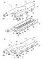
図1、図2は、本発明の参考例1に係るオイルストレーナ1を示す。このオイルストレーナ1は、全体として水平方向に延びる略四角箱状をなしており、長手方向が車幅方向に一致するように、自動車のトランスミッションの比較的浅いオイルパン内に配設されている。(Reference Example 1)
1 and 2 show an
オイルストレーナ1は、上下方向に分割されており、上側分割体2(第2分割体)と、この上側分割体2の下方に配置された下側分割体4(第1分割体)との二部品で構成されている。つまり、オイルストレーナ1は、鉛直方向と直角をなす水平方向に沿って切ることにより、上側分割体2と下側分割体4とに分割されている。 The
上側分割体2は、樹脂材を射出成形してなるものであって、水平方向に延びる略矩形状の頂壁部20と、この頂壁部20の外周部から下側分割体4側へ延びるように全周に亘って形成された周壁部21とを備えている。頂壁部20の中央部には、円管状のオイル流出部22が、上方かつ長手方向一方側に延びた後該一方側に延びるように突設されている。このオイル流出部22の上流端部は、頂壁部20からオイルストレーナ1のオイル流入空間(オイル流入室)R内に下方かつ長手方向他方側に突出しており、その上流端開口22aはオイルパン内のオイルの液面が動いてもオイル流入空間R内のオイルに浸るように、オイル流入空間Rに臨んでいる。一方、オイル流出部22の下流端開口22bは、下流端部に形成された段部にシール材(不図示)を組み付けた後、トランスミッションのオイルポンプの吸入口に接続される。オイル流出部22と頂壁部20との間には、補強用のリブ23が設けられている。周壁部21は、略四角環状の内側壁部24と、この内側壁部24の外周囲に配置され、内側壁部24との間に略四角環状の嵌入溝部25を形成し、内側壁部24と互いに連結された略四角環状の外側壁部26との二重壁で構成されている。これらの内側及び外側壁部24,26は、互いに頂壁部20の短手方向に対向する一対の長壁部24a,26a(長壁部24aは図1、図2では不図示)と、互いに頂壁部20の長手方向に対向する一対の短壁部24b,26bとで構成されている。外側壁部26における両長壁部26aの外周側側面の下端縁部には、係合爪部27(係合部)が、下側分割体4側へ延びるように所定間隔を開けて3つずつ形成されている。外側壁部26における両短壁部26bの外周側側面の下端縁部には、係合爪部27が、下側分割体4側へ延びるように1つずつ形成されている。係合爪部27と下側分割体4の嵌入壁部43との間には、外側壁部26の下端縁部が外方に向かって張り出すことによって隙間(撓み代)Gが形成されている。このように隙間Gを形成すると、係合爪部27を下側分割体4の被係合孔部45に係合する際、係合爪部27が容易に撓み、係合が容易になる。 The upper divided
下側分割体4は、樹脂材と金属材(具体的には金属製のフィルタ部42)とをインサート成形してなるものであって、水平方向に延びる略矩形状の底壁部40と、この底壁部40の外周部から上側分割体2側へ延びるように全周に亘って形成された周壁部41とを備えている。底壁部40には、金属製のフィルタ部42(金属メッシュ)が略全体に亘って形成されている。このフィルタ部42は、オイル濾過用の網目を構成する孔部42aを多数有し、全体として略矩形状に形成されている。周壁部41は、上側分割体2の嵌入溝部25に嵌入する略四角環状の嵌入壁部43を構成している。この嵌入壁部43は、互いに底壁部40の短手方向に対向する一対の長壁部43aと、互いに底壁部40の長手方向に対向する一対の短壁部43bとで構成されている。嵌入壁部43の外周側側面には、突条シール部43cが全周に亘って形成されている。嵌入壁部43の下端縁部には、板状のフランジ部44が、外方に向かって全周に亘って張出し形成されている。このフランジ部44は、互いに底壁部40の短手方向に対向する一対の長壁部44aと、互いに底壁部40の長手方向に対向する一対の短壁部44bとで構成されている。両長壁部44aには、上側分割体2の外側壁部26長壁部26aの係合爪部27に係合する被係合孔部45(被係合部)が、該係合爪部27に対応するように所定間隔を開けて3つずつ形成されている。両短壁部44bには、上側分割体2の外側壁部26短壁部26bの係合爪部27に係合する被係合孔部45が、該係合爪部27に対応するように1つずつ形成されている。 The lower divided
そして、上側分割体2と下側分割体4とを内部にオイル流入空間Rが形成されるように各々の開放側を向かい合わせ、下側分割体4の嵌入壁部43を上側分割体2の嵌入溝部25に嵌入した状態で、上側分割体2の係合爪部27が下側分割体4の被係合孔部45に挿入されて被係合孔部45の周縁部に係止された状態で結合し、オイルストレーナ1が組み立てられている。 Then, the upper divided
このように組み立てられたオイルストレーナ1では、下側分割体4の嵌入壁部43が上側分割体2の嵌入溝部25に嵌入して、嵌入壁部43の内周側側面が上側分割体2の内側壁部24の外周側側面に対向当接(面接触)しているとともに、嵌入壁部43の外周側側面が上側分割体2の外側壁部26の内周側側面に対向している。また、嵌入壁部43の外周側側面の突条シール部43cが、外側壁部26の内周側側面に圧接(線接触)している。 In the
上記のように構成したオイルストレーナ1はオイルパン内に収容され、オイル流出部22がトランスミッションに取り付けられる。この状態でトランスミッションが始動すると、オイルパン内のオイルがフィルタ部42の孔部42aを通過して濾過され、オイル流出部22から流出してオイルポンプを経てトランスミッションの摺動部に供給される。 The
本参考例においては、内側壁部24及び嵌入壁部43の当接と外側壁部26及び嵌入壁部43の当接とによる2段階のシール構造により、上側分割体2と下側分割体4との間のシール性が確実に得られる。また、嵌入壁部43の突条シール部43cが、外側壁部26に圧接しているので、シール性がより一層確実なものとなる。詳しくは、オイルポンプによるオイルの吸引中には、エアーやオイルパン内のオイルがオイルポンプの吸引力によって上側分割体2と下側分割体4との合わせ部の隙間からオイルストレーナ1のオイル流入空間Rに流入することが防止され、その結果、オイルの吸い上げ不良が発生することが防止されるとともに、濾過されていないオイルのエンジンへの供給が防止される。 In the present reference example, the upper divided
−効果−
以上より、本参考例によれば、上側分割体2の合わせ部に、内側壁部24と、この内側壁部24との間に嵌入溝部25を形成する外側壁部26とを全周に亘って形成しており、下側分割体4の合わせ部に、嵌入溝部25に嵌入する嵌入壁部43を全周に亘って形成しているので、内側壁部24及び嵌入壁部43の当接と外側壁部26及び嵌入壁部43の当接とによる2段階のシール構造により、上側分割体2と下側分割体4との間のシール性を確保することができ、そのシール性を従来のものと比較して向上させることができる。-Effect-
As described above, according to the present reference example, the
また、外側壁部26に係合爪部27を形成しており、嵌入壁部43に係合爪部27に係合する被係合孔部45を形成しているので、嵌入壁部43及び嵌入溝部25の係合と係合爪部27及び被係合孔部45の係合による2つの係合構造により、上側分割体2と下側分割体4とを一体化させることができ、フィルタ部42が脱落することを従来のものと比較して抑制することができる。 Further, since the engaging
以上により、簡単な構造で、上側分割体2と下側分割体4との間のシール性を向上させるとともに、フィルタ部42が脱落することを抑制することができる。 As described above, with a simple structure, it is possible to improve the sealing property between the upper divided
(参考例2)
図3は、本発明の参考例2に係るオイルストレーナ1を示す。参考例2では、内側及び外側壁部46,48を下側分割体4に、嵌入壁部28を上側分割体2に形成している。(Reference Example 2)
FIG. 3 shows an
下側分割体4の周壁部41における上端側略半分の部分は、略四角環状の内側壁部46と、この内側壁部46の外周囲に配置され、内側壁部46との間に略四角環状の嵌入溝部47を形成し、内側壁部46と互いに連結された略四角環状の外側壁部48との二重壁で構成されている。内側及び外側壁部46,48は、互いに底壁部40の短手方向に対向する一対の長壁部46a,48aと、互いに底壁部40の長手方向に対向する一対の短壁部46b,48bとで構成されている。外側壁部48の両長壁部48aの上端縁部には、係合爪部49(係合部)が、上側分割体2側へ延びるように所定間隔を開けて3つずつ形成されている。外側壁部48における両短壁部48bの上端縁部には、係合爪部49が、上側分割体2側へ延びるように1つずつ形成されている。 A substantially half portion at the upper end side of the
上側分割体2の周壁部21における下端側略半分の部分は、下側分割体4の嵌入溝部47に嵌入する略四角環状の嵌入壁部28を構成している。この嵌入壁部28は、互いに頂壁部20の短手方向に対向する一対の長壁部28aと、互いに頂壁部20の長手方向に対向する一対の短壁部28bとで構成されている。長壁部28aの外周側側面の上端縁部(周壁部21の外周側側面の上下方向中央部)には、下側分割体4の外側壁部48長壁部48aの係合爪部49に係合するコ字状の被係合部29が、該係合爪部49に対応するように所定間隔を開けて3つずつ形成されている。短壁部28bの外周側側面の上端縁部(周壁部21の外周側側面の上下方向中央部)には、下側分割体4の外側壁部48短壁部48bの係合爪部49に係合するコ字状の被係合部29が、該係合爪部49に対応するように1つずつ形成されている。嵌入壁部28の外周側側面における被係合部29の下方の部分には、突条シール部28cが全周に亘って形成されている。 A substantially half portion on the lower end side of the
その他の構成は参考例1と同じであるので、同一の構成箇所には同一の符号を付してその詳細な説明は省略する。 Since the other configuration is the same as that of the reference example 1, the same components are denoted by the same reference numerals, and detailed description thereof is omitted.
そして、上側分割体2と下側分割体4とを内部にオイル流入空間Rが形成されるように各々の開放側を向かい合わせ、上側分割体2の嵌入壁部28を下側分割体4の嵌入溝部47に嵌入した状態で、下側分割体4の係合爪部49が上側分割体2の被係合部29内に挿入されて被係合部29に係止された状態で結合し、オイルストレーナ1が組み立てられている。 Then, the upper divided
このように組み立てられたオイルストレーナ1では、上側分割体2の嵌入壁部28が下側分割体4の嵌入溝部47に嵌入して、嵌入壁部28の内周側側面が下側分割体4の内側壁部46の外周側側面に対向当接しているとともに、嵌入壁部28の外周側側面が下側分割体4の外側壁部48の内周側側面に対向している。また、嵌入壁部28の外周側側面の突条シール部28cが、外側壁部48の内周側側面に圧接している。 In the
以上により、本参考例によれば、参考例1と同じ効果が得られる。 As described above, according to the present reference example, the same effects as those of the reference example 1 can be obtained.
(実施形態1)
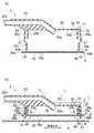
図4、図5は、本発明の実施形態1に係るオイルストレーナ1を示す。実施形態1では、エアー抜き用の開口部30を上側分割体2の頂壁部20に形成している。(Embodiment 1)
4 and 5 show an
オイルストレーナ1は、エンジンの比較的浅いオイルパンP内に配設されている。オイルパンP内のオイルの液面を符号Lで示す。 The
上側分割体2のオイル流出部22の下流端開口22bは、エンジンのオイルポンプの吸入口に接続される。上側分割体2の頂壁部20の長手方向両端部には、エアー抜き用の網目を構成する開口部30が多数、一体成形されており、これらの開口部30は、全体として略矩形状に形成されている。 A downstream end opening 22b of the
その他の構成は参考例1と同じであるので、同一の構成箇所には同一の符号を付してその詳細な説明は省略する。 Since the other configuration is the same as that of the reference example 1, the same components are denoted by the same reference numerals, and detailed description thereof is omitted.
そして、上記のように構成したオイルストレーナ1はオイルパンP内に収容され、オイル流出部22がエンジンに取り付けられる。この状態でエンジンが始動すると、オイルパンP内のオイルがフィルタ部42の孔部42aを通過して濾過され、オイル流出部22から流出してオイルポンプを経てエンジンの摺動部に供給される。 And the
オイルストレーナ1の使用中に例えば自動車の旋回等によって仮想線で示すようにオイルパンP内のオイルの液面Lが動いてオイル流入空間R内のオイルが長手方向(車幅方向)一方側に片寄り、この片寄りによってオイル流入空間R内の該一方側とは反対側の他方側の端部の空間Sにフィルタ部42の該他方側の端部の孔部42aからエアーが入り込んでも、この空間Sに入り込んだエアーは、オイル流入空間R内のオイルが元の状態に戻ると、該他方側の端部の開口部30から抜けていく。 While the
−効果−
以上により、本実施形態によれば、参考例1と同じ効果が得られるとともに、エアーを吸い込んでオイルの吸い上げ不良が発生することを抑制することができる。-Effect-
As described above, according to the present embodiment, the same effect as in Reference Example 1 can be obtained, and it is possible to suppress the occurrence of poor oil suction by sucking air.
このようにオイルストレーナ1は、比較的浅いオイルパンP内に配設されていても、オイルが連続して吸い上げられる形状構造となっている。 As described above, the
(実施形態2)
図6〜図8は、本発明の実施形態2に係るオイルストレーナ1を示す。実施形態2では、上側分割体2の内側及び外側壁部24,26の周方向の一部を頂壁部20よりも上方に突出させている。(Embodiment 2)
6 to 8 show an
オイルストレーナ1は、エンジンの比較的浅いオイルパンP内に配設されている。オイルパンP内のオイルの液面を符号Lで示す。 The
上側分割体2の内側及び外側壁部24,26の両短壁部24b,26bは、全部が頂壁部20よりも上方に突出している。つまり、両短壁部24b,26bは、頂壁部20から下側分割体4側とは反対側へ延びている。上側分割体2における内側及び外側壁部24,26の両長壁部24a,26aの長手方向両端部は、一部が頂壁部20よりも上方に突出している。内側及び外側壁部24,26の両長壁部24a,26aの上端縁面及び下端縁面は、長手方向中央が下側分割体4側に突出する湾曲状に形成されている。つまり、嵌入溝部25の底面は、長手方向中央が下側分割体4側に突出する湾曲状に形成されている。内側及び外側壁部24,26における両長壁部24a,26aの上端縁面の長手方向中央部は、頂壁部20と面一となっている。つまり、内側及び外側壁部24,26の両長壁部24a,26aの長手方向中央部は、頂壁部20から下側分割体4側へ延びている。このように面一となっていると、頂壁部20の上に溜まったオイルが、内側及び外側壁部24,26における両長壁部24a,26aの上端縁面の長手方向中央部から排出される。上側分割体2のオイル流出部22は、頂壁部20の中央部に、上方に延びた後短手方向一方側に延びるように突設されている。このオイル流出部22の上流端部は、頂壁部20からオイル流入空間R内に下方に突出している。オイル流出部22の下流端開口22bは、エンジンのオイルポンプの吸入口に接続される。 All of the
下側分割体4の底壁部40は、長手方向中央が下方に突出する湾曲状に形成されている。下側分割体4の嵌入壁部43は、内側及び外側壁部24,26(嵌入溝部25)や底壁部40の形状に対応するように形成されている。つまり、嵌入壁部43の両長壁部43aの上端縁面及び下端縁面は、長手方向中央が下方に突出する湾曲状に形成されている。フランジ部44は、嵌入壁部43の形状に対応するように形成されている。つまり、フランジ部44の両長壁部44aは、長手方向中央が下方に突出する湾曲状に形成されている。 The
その他の構成は参考例1と同じであるので、同一の構成箇所には同一の符号を付してその詳細な説明は省略する。 Since the other configuration is the same as that of the reference example 1, the same components are denoted by the same reference numerals, and detailed description thereof is omitted.
そして、組み立てられたオイルストレーナ1では、下側分割体4の底壁部40(フィルタ部42)が長手方向中央側から両端側に行くに従って上側分割体2の頂壁部20に接近して、頂壁部20と底壁部40との距離が長手方向中央側から両端側に行くに従って短くなる。つまり、オイル流入空間Rの上下方向長さが長手方向中央側から両端側に行くに従って短くなる。 And in the assembled
上記のように構成したオイルストレーナ1はオイルパンP内に収容され、オイル流出部22がエンジンに取り付けられる。この状態でエンジンが始動すると、オイルパンP内のオイルがフィルタ部42の孔部42aを通過して濾過され、オイル流出部22から流出してオイルポンプを経てエンジンの摺動部に供給される。 The
オイルストレーナ1の使用中に例えば自動車の旋回等によって仮想線で示すようにオイルパンP内のオイルの液面Lが動いてオイル流入空間R内のオイルが長手方向(車幅方向)一方側に片寄り、この片寄りによってオイル流入空間R内の該一方側とは反対側の他方側の端部の空間Sにフィルタ部42の該他方側の端部の孔部42aからエアーが入り込んでも、この空間Sに入り込んだエアーは、下側分割体4の底壁部40(フィルタ部42)が上側分割体2の頂壁部20に接近していることによって、少量となる。そして、この少量のエアーは、オイル流入空間R内のオイルが元の状態に戻ると、フィルタ部42の該他方側の端部の孔部42aからほとんど抜けていく。 While the
−効果−
以上により、本実施形態によれば、参考例1と同じ効果が得られるとともに、エアーを吸い込んでオイルの吸い上げ不良が発生することを抑制することができる。-Effect-
As described above, according to the present embodiment, the same effect as in Reference Example 1 can be obtained, and it is possible to suppress the occurrence of poor oil suction by sucking air.
このようにオイルストレーナ1は、比較的浅いオイルパンP内に配設されていても、エアーが吸い込まれにくい形状構造となっている。 Thus, even if the
尚、本実施形態では、上側分割体2の内側及び外側壁部24,26は、周方向の一部が頂壁部20よりも上方に突出しているが、周方向の全部が上側分割体2の頂壁部20よりも上方に突出してもよい。 In the present embodiment, the inner and
また、本実施形態では、内側及び外側壁部24,26の両長壁部24a,26aの上端縁面及び下端縁面等は、湾曲状に形成されているが、これに限らず、例えば、V字状に形成されてもよい。 In the present embodiment, the upper edge surface and the lower edge surface of both the
(実施形態3)
図9は、本発明の実施形態3に係るオイルストレーナ1を示す。実施形態3では、フィルタ部42を下側分割体4の底壁部40及び周壁部41に設けている。(Embodiment 3)
FIG. 9 shows an
オイルストレーナ1は、エンジンの比較的浅いオイルパン内に配設されている。 The
上側分割体2の内側及び外側壁部24,26は、全部が頂壁部20よりも上方に突出している。つまり、内側及び外側壁部24,26は、頂壁部20から下側分割体4側とは反対側へ延びている。内側及び外側壁部24,26の両短壁部24b,26bの上端縁面は、下方に窪んでいる。このように窪んでいると、頂壁部20の上に溜まったオイルが、内側及び外側壁部24,26における両短壁部24b,26bの該窪み部から排出される。上側分割体2のオイル流出部22は、頂壁部20の中央部の短手方向一方側寄りに、上方に延びた後該一方側に延びるように突設されており、内側及び外側壁部24,26の該一方側の長壁部24a,26aに接触している。このように接触していると、上側分割体2の射出成形時の型抜きが容易になる。オイル流出部22の上流端部は、頂壁部20からオイル流入空間R内に下方に突出している。オイル流出部22の下流端開口22bは、エンジンのオイルポンプの吸入口に接続される。 All of the inner and
下側分割体4における底壁部40及び周壁部41四面全ての下端側略半分の部分は、フィルタ部42で構成されている。このフィルタ部42は、全体として略四角箱状に一体成形されている。フィルタ部42には、補強用のリブ50が格子状に設けられている。周壁部41の上端側略半分の部分は、嵌入壁部43を構成している。 The
その他の構成は参考例1と同じであるので、同一の構成箇所には同一の符号を付してその詳細な説明は省略する。 Since the other configuration is the same as that of the reference example 1, the same components are denoted by the same reference numerals, and detailed description thereof is omitted.
そして、上記のように構成したオイルストレーナ1はオイルパン内に収容され、オイル流出部22がエンジンに取り付けられる。この状態でエンジンが始動すると、オイルパン内のオイルがフィルタ部42の孔部42aを通過して濾過され、オイル流出部22から流出してオイルポンプを経てエンジンの摺動部に供給される。 And the
オイルストレーナ1の使用中に例えば自動車の旋回等によってオイルパン内のオイルの液面が動いてオイル流入空間R内のオイルが長手方向(車幅方向)一方側に片寄り、この片寄りによってオイル流入空間R内の該一方側とは反対側の他方側の端部の空間にフィルタ部42の該他方側の端部の孔部42aからエアーが入り込んでも、この空間に入り込んだエアーは、オイル流入空間R内のオイルが元の状態に戻ると、フィルタ部42の該他方側の端部の孔部42aから抜けていく。 While the
以上により、本実施形態によれば、参考例1と同じ効果が得られる。 As described above, according to the present embodiment, the same effect as in Reference Example 1 can be obtained.
尚、本実施形態では、下側分割体4における底壁部40及び周壁部41四面全てのフランジ部44の下方の部分は、フィルタ部42で構成されているが、これに限らず、例えば、下側分割体4における底壁部40及び周壁部41の少なくとも一面が、フィルタ部42で構成されてもよい。 In addition, in this embodiment, the bottom part of the
(参考例3)
図10、図11は、本発明の参考例3に係るオイルストレーナ1を示す。参考例3では、第1及び第2分割体8,6の分割方向は、水平方向である。(Reference Example 3 )
10 and 11 show an
オイルストレーナ1は、エンジンの比較的浅いオイルパン内に配設されている。オイルストレーナ1は、水平方向(図10では左右方向)に分割されており、第1分割体8と第2分割体6との二部品で構成されている。つまり、オイルストレーナ1は、水平方向と直角をなす鉛直方向に沿って切ることにより、第1分割体8と第2分割体6とに分割されている。 The
第2分割体6は、樹脂材を射出成形してなるものであって、第1分割体8側に向かって略矩形状に開口した略四角箱状のものである。第2分割体6の開口側とは反対側の部分には、円管状のオイル流出部60が、上方かつ該反対側に延びるように突設されている。このオイル流出部60の下流端開口60aは、エンジンのオイルポンプの吸入口に接続される。第2分割体6の開口周縁部61には、板状のフランジ部63が、外方に向かって全周に亘って張出し形成されている。このフランジ部63における内周縁よりも外周側でかつ外周縁よりも内周側の部分には、第1分割体8側へ延びるように全周に亘って形成され、第1分割体8の嵌入溝部84に嵌入する略四角環状の嵌入壁部62が形成されている。この嵌入壁部62の外周側側面には、突条シール部62aが全周に亘って形成されている。フランジ部63における嵌入壁部62よりも外周側の部分には、第1分割体8側へ延びるように全周に亘って形成された略四角環状の周壁部64が形成されている。この周壁部64には、第1分割体8の係合爪部86に係合する被係合孔部65(被係合部)が複数形成されている。 The second divided
第1分割体8は、樹脂材と金属材(具体的には金属製のフィルタ部81)とをインサート成形してなるものであって、第2分割体6側に向かって略矩形状に開口した略四角箱状のものである。第1分割体8の底壁部80には、金属製のフィルタ部81が略全体に亘って形成されている。第1分割体8の開口周縁部82には、略四角環状の内側壁部83と、この内側壁部83の外周囲に配置され、内側壁部83との間に略四角環状の嵌入溝部84を形成し、内側壁部83と互いに連結された略四角環状の外側壁部85との二重壁が全周に亘って形成されている。この外側壁部85には、係合爪部86(係合部)が、第2分割体6の被係合孔部65に対応するように複数形成されている。この係合爪部86の両脇には、スリット87が形成されている。このようにスリット87を形成すると、係合爪部86を被係合孔部65に係合する際、係合爪部86が容易に撓み、該係合が容易になる。 The first divided
その他の構成は参考例1と同じであるので、同一の構成箇所には同一の符号を付してその詳細な説明は省略する。 Since the other configuration is the same as that of the reference example 1, the same components are denoted by the same reference numerals, and detailed description thereof is omitted.
そして、第1分割体8と第2分割体6とを内部にオイル流入空間Rが形成されるように各々の開放側を向かい合わせ、第2分割体6の嵌入壁部62を第1分割体8の嵌入溝部84に嵌入した状態で、第1分割体8の係合爪部86が第2分割体6の被係合孔部65に挿入されて係止された状態で結合し、オイルストレーナ1が組み立てられている。 Then, the first divided
このように組み立てられたオイルストレーナ1では、第2分割体6の嵌入壁部62が第1分割体8の嵌入溝部84に嵌入して、嵌入壁部62の内周側側面が第1分割体8の内側壁部83の外周側側面に対向当接しているとともに、嵌入壁部62の外周側側面が第1分割体8の外側壁部85の内周側側面に対向している。また、嵌入壁部62の外周側側面の突条シール部62aが、外側壁部85の内周側側面に圧接している。さらに、外側壁部85の外周側側面が第2分割体6の周壁部64の内周側側面に対向当接している。 In the
上記のように構成したオイルストレーナ1はオイルパン内に収容され、オイル流出部60がエンジンに取り付けられる。この状態でエンジンが始動すると、オイルパン内のオイルがフィルタ部81の孔部81aを通過して濾過され、オイル流出部60から流出してオイルポンプを経てエンジンの摺動部に供給される。 The
−効果−
以上により、本参考例によれば、参考例1と同じ効果が得られる。-Effect-
As described above, according to the presentreference example , the same effects as those of the reference example 1 can be obtained.
また、第1及び第2分割体8,6の分割方向は水平方向であるので、本参考例のように、オイル流出部60を第2分割体6から水平方向に延びるように設けること等により、オイルストレーナ1をコンパクトにすることができる。Further, since the dividing direction of the first and second divided
このようにオイルストレーナ1は、比較的浅いオイルパンP内に配設することに適した形状構造となっている。 Thus, the
尚、オイルストレーナ1の構成は、上記のものに限定されない。 The configuration of the
例えば、図12に示すようなものにしてもよい。つまり、第2分割体6の底壁部における第1分割体8側の端縁部に下方に垂下する垂下壁部66を形成する。この垂下壁部66の下端縁部に嵌入壁部62を形成する。第1分割体8の頂壁部における第2分割体6側の端縁部に上方に立ち上がる立ち上がり壁部88を形成する。この立ち上がり壁部88の上端縁部に内側及び外側壁部83,85を形成する。オイル流出部60を第2分割体6の開口側とは反対側の部分から該反対側に延びるように突設する。 For example, it may be as shown in FIG. That is, the hanging
また、図13に示すようなものにしてもよい。つまり、第2分割体6の頂壁部における第1分割体8側の端縁部に下方に垂下する垂下壁部を形成する。この垂下壁部は嵌入壁部62のフランジ部63を兼ねる。第2分割体6の底壁部に下方に落ちる段差壁部67を形成する。オイル流出部60を第2分割体6の開口側とは反対側の部分から該反対側に延びるように突設する。 Moreover, you may make it as shown in FIG. That is, a drooping wall portion that hangs downward is formed at the edge of the top wall portion of the second divided
さらに、本参考例では、第1及び第2分割体8,6の分割方向は水平方向であるので、図示は省略するが、オイルパン内に障害物が多くても、オイル流出部60の形状構造等を工夫することにより、そのようなオイルパンに適した形状構造となったオイルストレーナ1を実現することができる。Further, in thisreference example , the dividing direction of the first and second divided
また、図10、図12、図13では、フィルタ部81は、第1分割体8の底壁部80に形成されているが、周壁部や頂壁部に形成されてもよい。 10, 12, and 13, the
(その他の実施形態)
上記参考例1及び2では、オイルストレーナ1は、トランスミッションのオイルパン内に配設されているが、これに限らず、例えば、エンジンのオイルパン内に配設してもよい。(Other embodiments)
In the reference examples 1 and 2, the
一方、上記参考例3及び実施形態1〜3では、オイルストレーナ1は、エンジンのオイルパン内に配設されているが、これに限らず、例えば、トランスミッションのオイルパン内に配設してもよい。On the other hand, inReference Example 3 and
また、第1及び第2分割体は、その分割方向から見て、略矩形状であるが、多角形状や楕円状、円状であってもよい。 The first and second divided bodies have a substantially rectangular shape when viewed from the dividing direction, but may be polygonal, elliptical, or circular.
さらに、内側壁部と外側壁部、嵌入壁部は、第1及び第2分割体の分割方向から見て、略矩形状であるが、多角形状や楕円状、円状であってもよい。 Further, the inner wall portion, the outer wall portion, and the fitting wall portion are substantially rectangular when viewed from the dividing direction of the first and second divided bodies, but may be polygonal, elliptical, or circular.
また、上記各参考例及び各実施形態では、下側分割体4や第2分割体8は、樹脂材と金属材とをインサート成形してなるものであるが、これに限らず、例えば、樹脂材を射出成形してなるものであってもよい。この場合、下側分割体4や第2分割体8に、樹脂製のフィルタ部が一体成形される。このフィルタ部の網目は、下側分割体4や第2分割体8の成形型に設けられた網目形成面によって下側分割体4や第2分割体8の成形時に成形される。このように樹脂材を射出成形してなるものにすると、樹脂材と金属材とをインサート成形してなるものと比較して、フィルタ部の孔部は若干大きくなるが、コストを削減することができる。 Moreover, in each said reference example and each embodiment, although the lower
さらに、両分割体の合わせ部の構成は、上記のものに限定されない。 Furthermore, the structure of the joint part of both divided bodies is not limited to the above.
例えば、突条シール部は、嵌入壁部の内周側側面に形成したり、両側側面に形成したりしてもよい。或いは、形成しなくてもよい。この場合、嵌入壁部の内周側側面が内側壁部の外周側側面に、外周側側面が外側壁部の内周側側面に対向当接(面接触)する。 For example, the protrusion seal portion may be formed on the inner peripheral side surface of the fitting wall portion or may be formed on both side surfaces. Alternatively, it may not be formed. In this case, the inner peripheral side surface of the fitting wall portion is in abutting contact (surface contact) with the outer peripheral side surface of the inner wall portion, and the outer peripheral side surface is opposed to the inner peripheral side surface of the outer wall portion.
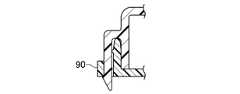
また、図14に示すように、嵌入壁部のフランジ部の外周部に、係合爪部の外側面が対向当接する周壁部90が全周に亘って形成されてもよい。 Moreover, as shown in FIG. 14, the surrounding
さらに、図15に示すように、内側壁部の先端縁部に、先端縁側に行くに従って外方に傾斜する傾斜面が形成されており、嵌入壁部の基端縁部に、基端縁側に行くに従って外方に傾斜する傾斜面が形成され、嵌入壁部との間に内側壁部の先端縁部が嵌入する第2嵌入溝部91を形成する周壁部92が全周に亘って形成されてもよい。このように周壁部92を形成すると、内側壁部が内方に撓むことが防止される。 Further, as shown in FIG. 15, an inclined surface that is inclined outward toward the distal end edge side is formed at the distal end edge portion of the inner wall portion, and at the proximal end edge side of the fitting wall portion, on the proximal end edge side. An inclined surface that is inclined outward as it goes is formed, and a
また、図16に示すように、嵌入壁部の基端縁部に、係合爪部の内側面の先端部が対向当接する当接部93が、嵌入壁部の先端縁側とは反対側(嵌入壁部の突出方向とは逆方向)に突出しかつ係合爪部側に傾斜するように形成されてもよい。このように当接部93を形成すると、係合爪部が被係合孔部に係合された後、係合爪部が内方に撓むことが防止される。 Further, as shown in FIG. 16, an abutting
さらに、係合爪部及び被係合孔部(被係合部)の数や位置は、上記のものに限定されず、その数等は任意である。 Furthermore, the numbers and positions of the engaging claw portions and the engaged hole portions (engaged portions) are not limited to those described above, and the number and the like are arbitrary.
また、本発明の趣旨を逸脱しない限り、上記各参考例及び各実施形態の構成要素を任意に組み合わせてもよい。 In addition, the constituent elements of the reference examples and the embodiments may be arbitrarily combined without departing from the spirit of the invention.
本発明は、実施形態に限定されず、その精神又は主要な特徴から逸脱することなく他の色々な形で実施することができる。 The present invention is not limited to the embodiments, and can be implemented in various other forms without departing from the spirit or main features thereof.
このように、上述の実施形態はあらゆる点で単なる例示に過ぎず、限定的に解釈してはならない。本発明の範囲は特許請求の範囲によって示すものであって、明細書には何ら拘束されない。さらに、特許請求の範囲の均等範囲に属する変形や変更は、全て本発明の範囲内のものである。 As described above, the above-described embodiment is merely an example in all respects and should not be interpreted in a limited manner. The scope of the present invention is defined by the claims, and is not limited by the specification. Further, all modifications and changes belonging to the equivalent scope of the claims are within the scope of the present invention.
以上説明したように、本発明に係るオイルストレーナは、簡単な構造で、第1分割体と第2分割体との間のシール性を向上させるとともに、フィルタ部が脱落することを抑制することが必要な用途等に適用することができる。 As described above, the oil strainer according to the present invention has a simple structure, improves the sealing performance between the first divided body and the second divided body, and suppresses the filter unit from falling off. It can be applied to necessary uses.
1 オイルストレーナ
2 上側分割体(第2分割体)
20 頂壁部
21 周壁部
22 オイル流出部
24 内側壁部
25 嵌入溝部
26 外側壁部
27 係合爪部(係合部)
28 嵌入壁部
29 被係合部
30 開口部
4 下側分割体(第1分割体)
40 底壁部
41 周壁部
42 フィルタ部
43 嵌入壁部
45 被係合孔部(被係合部)
46 内側壁部
47 嵌入溝部
48 外側壁部
49 係合爪部(係合部)
6 第1分割体
60 オイル流出部
62 嵌入壁部
65 被係合孔部(被係合部)
8 第2分割体
81 フィルタ部
83 内側壁部
84 嵌入溝部
85 外側壁部
86 係合爪部
R オイル流入空間1
20
28
40
46
6
8 Second divided
Claims (2)
Translated fromJapanese上記第1分割体(4)には、オイルを濾過して上記オイル流入空間(R)に流入させるフィルタ部(42)が設けられており、
上記第2分割体(2)には、上記オイル流入空間(R)に流入したオイルを流出させるオイル流出部(22)が設けられており、
上記第1及び第2分割体(4,2)の合わせ部の一方には、内側壁部(24)と、該内側壁部(24)との間に嵌入溝部(25)を形成する外側壁部(26)とが全周に亘って形成されており、他方には、該嵌入溝部(25)に嵌入する嵌入壁部(43)が全周に亘って形成されており、
上記外側壁部(26)には、係合部(27)が形成されており、上記嵌入壁部(43)には、該係合部(27)に係合する被係合部(45)が形成されており、
上記第1及び第2分割体(4,2)の分割方向は、上下方向であり、
上記第1分割体(4)は、上記第2分割体(2)の下方に配置されていて、上記フィルタ部(42)が設けられた底壁部(40)と、該底壁部(40)の外周部に全周に亘って形成された周壁部(41)とを備えており、
上記第2分割体(2)は、上記オイル流出部(22)が設けられた頂壁部(20)と、該頂壁部(20)の外周部に全周に亘って形成された周壁部(21)とを備えており、
上記第1及び第2分割体(4,2)の周壁部(41,21)の一方には、上記内側及び外側壁部(24,26)が形成されており、他方には、上記嵌入壁部(43)が形成されており、
上記第2分割体(2)の頂壁部(20)の長手方向端部には、エアー抜き用の開口部(30)が形成されていることを特徴とするオイルストレーナ。An oil strainer in which the first divided body (4) and the second divided body (2) are combined so as to form an oil inflow space (R),
The first divided body (4) is provided with a filter portion (42) for filtering oil to flow into the oil inflow space (R),
The second divided body (2) is provided with an oil outflow portion (22) through which oil flowing into the oil inflow space (R) flows out,
One of the mating portions of the first and second divided bodies (4, 2) has an inner wall portion (24) and an outer wall forming a fitting groove portion (25) between the inner wall portion (24). Part (26) is formed over the entire circumference, and on the other side, a fitting wall part (43) that fits into the fitting groove part (25) is formed over the whole circumference,
An engagement portion (27) is formed on the outer wall portion (26), and an engaged portion (45) that engages with the engagement portion (27) is formed on the fitting wall portion (43). Is formed,
The dividing direction of the first and second divided bodies (4, 2) is the vertical direction,
The first divided body (4) is disposed below the second divided body (2), and includes a bottom wall portion (40) provided with the filter portion (42), and the bottom wall portion (40 ) And a peripheral wall portion (41) formed over the entire circumference,
The second divided body (2) includes a top wall portion (20) provided with the oil outflow portion (22), and a peripheral wall portion formed on the outer peripheral portion of the top wall portion (20) over the entire circumference. (21)
The inner and outer wall portions (24, 26) are formed on one of the peripheral wall portions (41, 21) of the first and second divided bodies (4, 2), and the fitting wall is on the other side. Part (43) is formed,
An oil strainer characterized in that an air vent opening (30) is formed at the longitudinal end of the top wall (20) of the second divided body (2).
上記第1分割体(4)には、オイルを濾過して上記オイル流入空間(R)に流入させるフィルタ部(42)が設けられており、
上記第2分割体(2)には、上記オイル流入空間(R)に流入したオイルを流出させるオイル流出部(22)が設けられており、
上記第1及び第2分割体(4,2)の合わせ部の一方には、内側壁部(24)と、該内側壁部(24)との間に嵌入溝部(25)を形成する外側壁部(26)とが全周に亘って形成されており、他方には、該嵌入溝部(25)に嵌入する嵌入壁部(43)が全周に亘って形成されており、
上記外側壁部(26)には、係合部(27)が形成されており、上記嵌入壁部(43)には、該係合部(27)に係合する被係合部(45)が形成されており、
上記第1及び第2分割体(4,2)の分割方向は、上下方向であり、
上記第1分割体(4)は、上記第2分割体(2)の下方に配置されていて、上記フィルタ部(42)が設けられた底壁部(40)と、該底壁部(40)の外周部に全周に亘って形成された周壁部(41)とを備えており、
上記第2分割体(2)は、上記オイル流出部(22)が設けられた頂壁部(20)と、該頂壁部(20)の外周部に全周に亘って形成された周壁部(21)とを備えており、
上記第2分割体(2)の周壁部(21)には、上記内側及び外側壁部(24,26)が形成されており、上記第1分割体(4)の周壁部(41)には、上記嵌入壁部(43)が形成されており、
上記内側及び外側壁部(24,26)は、周方向の少なくとも一部が上記第2分割体(2)の頂壁部(20)よりも上方に突出していることを特徴とするオイルストレーナ。An oil strainer in which the first divided body (4) and the second divided body (2) are combined so as to form an oil inflow space (R),
The first divided body (4) is provided with a filter portion (42) for filtering oil to flow into the oil inflow space (R),
The second divided body (2) is provided with an oil outflow portion (22) through which oil flowing into the oil inflow space (R) flows out,
One of the mating portions of the first and second divided bodies (4, 2) has an inner wall portion (24) and an outer wall forming a fitting groove portion (25) between the inner wall portion (24). Part (26) is formed over the entire circumference, and on the other side, a fitting wall part (43) that fits into the fitting groove part (25) is formed over the whole circumference,
An engagement portion (27) is formed on the outer wall portion (26), and an engaged portion (45) that engages with the engagement portion (27) is formed on the fitting wall portion (43). Is formed,
The dividing direction of the first and second divided bodies (4, 2) is the vertical direction,
The first divided body (4) is disposed below the second divided body (2), and includes a bottom wall portion (40) provided with the filter portion (42), and the bottom wall portion (40 ) And a peripheral wall portion (41) formed over the entire circumference,
The second divided body (2) includes a top wall portion (20) provided with the oil outflow portion (22), and a peripheral wall portion formed on the outer peripheral portion of the top wall portion (20) over the entire circumference. (21)
The inner and outer wall portions (24, 26) are formed on the peripheral wall portion (21) of the second divided body (2), and the peripheral wall portion (41) of the first divided body (4) is formed on the peripheral wall portion (21). The insertion wall portion (43) is formed,
The oil strainer is characterized in that at least a part of the inner and outer wall portions (24, 26) in the circumferential direction protrudes above the top wall portion (20) of the second divided body (2).
Priority Applications (2)
| Application Number | Priority Date | Filing Date | Title |
|---|---|---|---|
| JP2010172470AJP5638306B2 (en) | 2010-07-30 | 2010-07-30 | Oil strainer |
| CN201110218875.5ACN102345481B (en) | 2010-07-30 | 2011-08-01 | Sump strainer |
Applications Claiming Priority (1)
| Application Number | Priority Date | Filing Date | Title |
|---|---|---|---|
| JP2010172470AJP5638306B2 (en) | 2010-07-30 | 2010-07-30 | Oil strainer |
Publications (2)
| Publication Number | Publication Date |
|---|---|
| JP2012031794A JP2012031794A (en) | 2012-02-16 |
| JP5638306B2true JP5638306B2 (en) | 2014-12-10 |
Family
ID=45544512
Family Applications (1)
| Application Number | Title | Priority Date | Filing Date |
|---|---|---|---|
| JP2010172470AExpired - Fee RelatedJP5638306B2 (en) | 2010-07-30 | 2010-07-30 | Oil strainer |
Country Status (2)
| Country | Link |
|---|---|
| JP (1) | JP5638306B2 (en) |
| CN (1) | CN102345481B (en) |
Families Citing this family (8)
| Publication number | Priority date | Publication date | Assignee | Title |
|---|---|---|---|---|
| JP6033641B2 (en)* | 2012-10-31 | 2016-11-30 | ダイキョーニシカワ株式会社 | Oil strainer |
| JP6068242B2 (en)* | 2013-04-16 | 2017-01-25 | ダイキョーニシカワ株式会社 | Filter and oil strainer |
| JP6289193B2 (en) | 2014-03-20 | 2018-03-07 | 株式会社ニフコ | Baffle plate for differential equipment |
| CN104454078B (en)* | 2014-10-30 | 2016-12-28 | 长城汽车股份有限公司 | Oil trap and oil trap assembly |
| TWI680007B (en)* | 2019-03-19 | 2019-12-21 | 康得倫事業有限公司 | Fluid collection device |
| JP7135994B2 (en)* | 2019-05-07 | 2022-09-13 | トヨタ自動車株式会社 | Vehicle oil supply mechanism |
| CN110185517B (en)* | 2019-06-27 | 2020-07-14 | 浙江吉利控股集团有限公司 | Strainer assembly and vehicle with same |
| EP3868457A1 (en)* | 2020-02-18 | 2021-08-25 | Mahle International GmbH | Filter arrangement |
Family Cites Families (6)
| Publication number | Priority date | Publication date | Assignee | Title |
|---|---|---|---|---|
| JPS6120244Y2 (en)* | 1981-05-27 | 1986-06-18 | ||
| JPH10169427A (en)* | 1996-12-13 | 1998-06-23 | Tokyo Roki Kk | Oil filter |
| JP4623468B2 (en)* | 2005-12-20 | 2011-02-02 | ダイキョーニシカワ株式会社 | Oil strainer |
| JP2007224782A (en)* | 2006-02-22 | 2007-09-06 | Daikyoo Nishikawa Kk | Oil strainer for vehicles |
| JP2009074370A (en)* | 2007-09-18 | 2009-04-09 | Daikyo Nishikawa Kk | Oil strainer for engine |
| JP4958733B2 (en)* | 2007-10-30 | 2012-06-20 | ダイキョーニシカワ株式会社 | Oil strainer |
- 2010
- 2010-07-30JPJP2010172470Apatent/JP5638306B2/ennot_activeExpired - Fee Related
- 2011
- 2011-08-01CNCN201110218875.5Apatent/CN102345481B/ennot_activeExpired - Fee Related
Also Published As
| Publication number | Publication date |
|---|---|
| JP2012031794A (en) | 2012-02-16 |
| CN102345481B (en) | 2016-05-04 |
| CN102345481A (en) | 2012-02-08 |
Similar Documents
| Publication | Publication Date | Title |
|---|---|---|
| JP5638306B2 (en) | Oil strainer | |
| JP6302338B2 (en) | Oil strainer | |
| US8097061B2 (en) | Elliptical seal interface for filter assembly | |
| US8043504B2 (en) | Filter cartridge | |
| CN101784761B (en) | Oil pan | |
| US10518200B2 (en) | No filter no run fluid filtration system | |
| CN102812230A (en) | A filter for an internal combustion engine | |
| JP5673209B2 (en) | Air cleaner intake duct connection structure | |
| US7510087B2 (en) | Case with partition member | |
| JP2024541458A (en) | Safety filter element, filter system and filter assembly | |
| KR101566019B1 (en) | Preliminary filter for a fuel delivery unit | |
| JP6771368B2 (en) | Separator seal structure | |
| JPH04330311A (en) | Delay member for lubricating oil | |
| JP4112937B2 (en) | Air cleaner for internal combustion engine | |
| KR20110007572A (en) | Oil Strainers For Engines | |
| EP3339623A1 (en) | Air cleaner for internal combustion engine | |
| JP4623468B2 (en) | Oil strainer | |
| JP6778299B2 (en) | Oil strainer | |
| JP4823609B2 (en) | Oil strainer | |
| JP2017133397A (en) | Oil strainer | |
| JP5368958B2 (en) | Oil strainer for engine | |
| KR20200096665A (en) | Intake filter device with air separation | |
| JP2009162336A (en) | Fluid conduit connection structure and oil strainer | |
| JP2016114026A (en) | Oil strainer | |
| JP4939317B2 (en) | Oil strainer |
Legal Events
| Date | Code | Title | Description |
|---|---|---|---|
| RD02 | Notification of acceptance of power of attorney | Free format text:JAPANESE INTERMEDIATE CODE: A7422 Effective date:20120724 | |
| A621 | Written request for application examination | Free format text:JAPANESE INTERMEDIATE CODE: A621 Effective date:20130610 | |
| A977 | Report on retrieval | Free format text:JAPANESE INTERMEDIATE CODE: A971007 Effective date:20140310 | |
| A131 | Notification of reasons for refusal | Free format text:JAPANESE INTERMEDIATE CODE: A131 Effective date:20140318 | |
| A521 | Request for written amendment filed | Free format text:JAPANESE INTERMEDIATE CODE: A523 Effective date:20140407 | |
| A02 | Decision of refusal | Free format text:JAPANESE INTERMEDIATE CODE: A02 Effective date:20140624 | |
| A521 | Request for written amendment filed | Free format text:JAPANESE INTERMEDIATE CODE: A523 Effective date:20140821 | |
| A911 | Transfer to examiner for re-examination before appeal (zenchi) | Free format text:JAPANESE INTERMEDIATE CODE: A911 Effective date:20140828 | |
| TRDD | Decision of grant or rejection written | ||
| A01 | Written decision to grant a patent or to grant a registration (utility model) | Free format text:JAPANESE INTERMEDIATE CODE: A01 Effective date:20140924 | |
| A61 | First payment of annual fees (during grant procedure) | Free format text:JAPANESE INTERMEDIATE CODE: A61 Effective date:20141022 | |
| R150 | Certificate of patent or registration of utility model | Ref document number:5638306 Country of ref document:JP Free format text:JAPANESE INTERMEDIATE CODE: R150 | |
| R250 | Receipt of annual fees | Free format text:JAPANESE INTERMEDIATE CODE: R250 | |
| R250 | Receipt of annual fees | Free format text:JAPANESE INTERMEDIATE CODE: R250 | |
| R250 | Receipt of annual fees | Free format text:JAPANESE INTERMEDIATE CODE: R250 | |
| R250 | Receipt of annual fees | Free format text:JAPANESE INTERMEDIATE CODE: R250 | |
| R250 | Receipt of annual fees | Free format text:JAPANESE INTERMEDIATE CODE: R250 | |
| R250 | Receipt of annual fees | Free format text:JAPANESE INTERMEDIATE CODE: R250 | |
| LAPS | Cancellation because of no payment of annual fees |