JP5636295B2 - Display state switching glasses - Google Patents
Display state switching glassesDownload PDFInfo
- Publication number
- JP5636295B2 JP5636295B2JP2011010175AJP2011010175AJP5636295B2JP 5636295 B2JP5636295 B2JP 5636295B2JP 2011010175 AJP2011010175 AJP 2011010175AJP 2011010175 AJP2011010175 AJP 2011010175AJP 5636295 B2JP5636295 B2JP 5636295B2
- Authority
- JP
- Japan
- Prior art keywords
- display state
- viewer
- state switching
- power supply
- glasses
- Prior art date
- Legal status (The legal status is an assumption and is not a legal conclusion. Google has not performed a legal analysis and makes no representation as to the accuracy of the status listed.)
- Expired - Fee Related
Links
Images


Classifications
- G—PHYSICS
- G02—OPTICS
- G02B—OPTICAL ELEMENTS, SYSTEMS OR APPARATUS
- G02B27/00—Optical systems or apparatus not provided for by any of the groups G02B1/00 - G02B26/00, G02B30/00
- G02B27/01—Head-up displays
- G02B27/017—Head mounted
- G02B27/0176—Head mounted characterised by mechanical features
- C—CHEMISTRY; METALLURGY
- C23—COATING METALLIC MATERIAL; COATING MATERIAL WITH METALLIC MATERIAL; CHEMICAL SURFACE TREATMENT; DIFFUSION TREATMENT OF METALLIC MATERIAL; COATING BY VACUUM EVAPORATION, BY SPUTTERING, BY ION IMPLANTATION OR BY CHEMICAL VAPOUR DEPOSITION, IN GENERAL; INHIBITING CORROSION OF METALLIC MATERIAL OR INCRUSTATION IN GENERAL
- C23C—COATING METALLIC MATERIAL; COATING MATERIAL WITH METALLIC MATERIAL; SURFACE TREATMENT OF METALLIC MATERIAL BY DIFFUSION INTO THE SURFACE, BY CHEMICAL CONVERSION OR SUBSTITUTION; COATING BY VACUUM EVAPORATION, BY SPUTTERING, BY ION IMPLANTATION OR BY CHEMICAL VAPOUR DEPOSITION, IN GENERAL
- C23C16/00—Chemical coating by decomposition of gaseous compounds, without leaving reaction products of surface material in the coating, i.e. chemical vapour deposition [CVD] processes
- C23C16/44—Chemical coating by decomposition of gaseous compounds, without leaving reaction products of surface material in the coating, i.e. chemical vapour deposition [CVD] processes characterised by the method of coating
- C23C16/448—Chemical coating by decomposition of gaseous compounds, without leaving reaction products of surface material in the coating, i.e. chemical vapour deposition [CVD] processes characterised by the method of coating characterised by the method used for generating reactive gas streams, e.g. by evaporation or sublimation of precursor materials
- A—HUMAN NECESSITIES
- A61—MEDICAL OR VETERINARY SCIENCE; HYGIENE
- A61B—DIAGNOSIS; SURGERY; IDENTIFICATION
- A61B3/00—Apparatus for testing the eyes; Instruments for examining the eyes
- A61B3/10—Objective types, i.e. instruments for examining the eyes independent of the patients' perceptions or reactions
- A61B3/113—Objective types, i.e. instruments for examining the eyes independent of the patients' perceptions or reactions for determining or recording eye movement
- A—HUMAN NECESSITIES
- A61—MEDICAL OR VETERINARY SCIENCE; HYGIENE
- A61B—DIAGNOSIS; SURGERY; IDENTIFICATION
- A61B5/00—Measuring for diagnostic purposes; Identification of persons
- A61B5/68—Arrangements of detecting, measuring or recording means, e.g. sensors, in relation to patient
- A61B5/6801—Arrangements of detecting, measuring or recording means, e.g. sensors, in relation to patient specially adapted to be attached to or worn on the body surface
- A61B5/6802—Sensor mounted on worn items
- A61B5/6803—Head-worn items, e.g. helmets, masks, headphones or goggles
- A—HUMAN NECESSITIES
- A61—MEDICAL OR VETERINARY SCIENCE; HYGIENE
- A61B—DIAGNOSIS; SURGERY; IDENTIFICATION
- A61B5/00—Measuring for diagnostic purposes; Identification of persons
- A61B5/74—Details of notification to user or communication with user or patient; User input means
- A61B5/742—Details of notification to user or communication with user or patient; User input means using visual displays
- A61B5/7445—Display arrangements, e.g. multiple display units
- C—CHEMISTRY; METALLURGY
- C23—COATING METALLIC MATERIAL; COATING MATERIAL WITH METALLIC MATERIAL; CHEMICAL SURFACE TREATMENT; DIFFUSION TREATMENT OF METALLIC MATERIAL; COATING BY VACUUM EVAPORATION, BY SPUTTERING, BY ION IMPLANTATION OR BY CHEMICAL VAPOUR DEPOSITION, IN GENERAL; INHIBITING CORROSION OF METALLIC MATERIAL OR INCRUSTATION IN GENERAL
- C23C—COATING METALLIC MATERIAL; COATING MATERIAL WITH METALLIC MATERIAL; SURFACE TREATMENT OF METALLIC MATERIAL BY DIFFUSION INTO THE SURFACE, BY CHEMICAL CONVERSION OR SUBSTITUTION; COATING BY VACUUM EVAPORATION, BY SPUTTERING, BY ION IMPLANTATION OR BY CHEMICAL VAPOUR DEPOSITION, IN GENERAL
- C23C16/00—Chemical coating by decomposition of gaseous compounds, without leaving reaction products of surface material in the coating, i.e. chemical vapour deposition [CVD] processes
- C23C16/04—Coating on selected surface areas, e.g. using masks
- C23C16/042—Coating on selected surface areas, e.g. using masks using masks
- A—HUMAN NECESSITIES
- A61—MEDICAL OR VETERINARY SCIENCE; HYGIENE
- A61B—DIAGNOSIS; SURGERY; IDENTIFICATION
- A61B2560/00—Constructional details of operational features of apparatus; Accessories for medical measuring apparatus
- A61B2560/02—Operational features
- A61B2560/0204—Operational features of power management
- A61B2560/0209—Operational features of power management adapted for power saving
- A—HUMAN NECESSITIES
- A61—MEDICAL OR VETERINARY SCIENCE; HYGIENE
- A61B—DIAGNOSIS; SURGERY; IDENTIFICATION
- A61B3/00—Apparatus for testing the eyes; Instruments for examining the eyes
- A61B3/10—Objective types, i.e. instruments for examining the eyes independent of the patients' perceptions or reactions
- A61B3/11—Objective types, i.e. instruments for examining the eyes independent of the patients' perceptions or reactions for measuring interpupillary distance or diameter of pupils
- A—HUMAN NECESSITIES
- A61—MEDICAL OR VETERINARY SCIENCE; HYGIENE
- A61B—DIAGNOSIS; SURGERY; IDENTIFICATION
- A61B5/00—Measuring for diagnostic purposes; Identification of persons
- A61B5/02—Detecting, measuring or recording for evaluating the cardiovascular system, e.g. pulse, heart rate, blood pressure or blood flow
- A61B5/026—Measuring blood flow
- A—HUMAN NECESSITIES
- A61—MEDICAL OR VETERINARY SCIENCE; HYGIENE
- A61B—DIAGNOSIS; SURGERY; IDENTIFICATION
- A61B5/00—Measuring for diagnostic purposes; Identification of persons
- A61B5/48—Other medical applications
- A61B5/4836—Diagnosis combined with treatment in closed-loop systems or methods
- A—HUMAN NECESSITIES
- A61—MEDICAL OR VETERINARY SCIENCE; HYGIENE
- A61B—DIAGNOSIS; SURGERY; IDENTIFICATION
- A61B5/00—Measuring for diagnostic purposes; Identification of persons
- A61B5/48—Other medical applications
- A61B5/4836—Diagnosis combined with treatment in closed-loop systems or methods
- A61B5/4839—Diagnosis combined with treatment in closed-loop systems or methods combined with drug delivery
- A—HUMAN NECESSITIES
- A61—MEDICAL OR VETERINARY SCIENCE; HYGIENE
- A61B—DIAGNOSIS; SURGERY; IDENTIFICATION
- A61B5/00—Measuring for diagnostic purposes; Identification of persons
- A61B5/48—Other medical applications
- A61B5/4848—Monitoring or testing the effects of treatment, e.g. of medication
- A—HUMAN NECESSITIES
- A61—MEDICAL OR VETERINARY SCIENCE; HYGIENE
- A61B—DIAGNOSIS; SURGERY; IDENTIFICATION
- A61B5/00—Measuring for diagnostic purposes; Identification of persons
- A61B5/74—Details of notification to user or communication with user or patient; User input means
- A61B5/742—Details of notification to user or communication with user or patient; User input means using visual displays
- A61B5/743—Displaying an image simultaneously with additional graphical information, e.g. symbols, charts, function plots
- G—PHYSICS
- G02—OPTICS
- G02B—OPTICAL ELEMENTS, SYSTEMS OR APPARATUS
- G02B27/00—Optical systems or apparatus not provided for by any of the groups G02B1/00 - G02B26/00, G02B30/00
- G02B27/01—Head-up displays
- G02B27/0101—Head-up displays characterised by optical features
- G02B2027/014—Head-up displays characterised by optical features comprising information/image processing systems
- G—PHYSICS
- G02—OPTICS
- G02B—OPTICAL ELEMENTS, SYSTEMS OR APPARATUS
- G02B27/00—Optical systems or apparatus not provided for by any of the groups G02B1/00 - G02B26/00, G02B30/00
- G02B27/01—Head-up displays
- G02B27/017—Head mounted
- G02B2027/0178—Eyeglass type
- G—PHYSICS
- G02—OPTICS
- G02B—OPTICAL ELEMENTS, SYSTEMS OR APPARATUS
- G02B30/00—Optical systems or apparatus for producing three-dimensional [3D] effects, e.g. stereoscopic images
- G02B30/20—Optical systems or apparatus for producing three-dimensional [3D] effects, e.g. stereoscopic images by providing first and second parallax images to an observer's left and right eyes
- G02B30/22—Optical systems or apparatus for producing three-dimensional [3D] effects, e.g. stereoscopic images by providing first and second parallax images to an observer's left and right eyes of the stereoscopic type
- G02B30/23—Optical systems or apparatus for producing three-dimensional [3D] effects, e.g. stereoscopic images by providing first and second parallax images to an observer's left and right eyes of the stereoscopic type using wavelength separation, e.g. using anaglyph techniques
- G—PHYSICS
- G02—OPTICS
- G02F—OPTICAL DEVICES OR ARRANGEMENTS FOR THE CONTROL OF LIGHT BY MODIFICATION OF THE OPTICAL PROPERTIES OF THE MEDIA OF THE ELEMENTS INVOLVED THEREIN; NON-LINEAR OPTICS; FREQUENCY-CHANGING OF LIGHT; OPTICAL LOGIC ELEMENTS; OPTICAL ANALOGUE/DIGITAL CONVERTERS
- G02F1/00—Devices or arrangements for the control of the intensity, colour, phase, polarisation or direction of light arriving from an independent light source, e.g. switching, gating or modulating; Non-linear optics
- G02F1/01—Devices or arrangements for the control of the intensity, colour, phase, polarisation or direction of light arriving from an independent light source, e.g. switching, gating or modulating; Non-linear optics for the control of the intensity, phase, polarisation or colour
- G02F1/13—Devices or arrangements for the control of the intensity, colour, phase, polarisation or direction of light arriving from an independent light source, e.g. switching, gating or modulating; Non-linear optics for the control of the intensity, phase, polarisation or colour based on liquid crystals, e.g. single liquid crystal display cells
- G02F1/133—Constructional arrangements; Operation of liquid crystal cells; Circuit arrangements
- G02F1/13306—Circuit arrangements or driving methods for the control of single liquid crystal cells
- G—PHYSICS
- G03—PHOTOGRAPHY; CINEMATOGRAPHY; ANALOGOUS TECHNIQUES USING WAVES OTHER THAN OPTICAL WAVES; ELECTROGRAPHY; HOLOGRAPHY
- G03B—APPARATUS OR ARRANGEMENTS FOR TAKING PHOTOGRAPHS OR FOR PROJECTING OR VIEWING THEM; APPARATUS OR ARRANGEMENTS EMPLOYING ANALOGOUS TECHNIQUES USING WAVES OTHER THAN OPTICAL WAVES; ACCESSORIES THEREFOR
- G03B35/00—Stereoscopic photography
- G03B35/16—Stereoscopic photography by sequential viewing
Landscapes
- Life Sciences & Earth Sciences (AREA)
- Health & Medical Sciences (AREA)
- Chemical & Material Sciences (AREA)
- Engineering & Computer Science (AREA)
- Physics & Mathematics (AREA)
- Surgery (AREA)
- Biomedical Technology (AREA)
- Molecular Biology (AREA)
- Animal Behavior & Ethology (AREA)
- Medical Informatics (AREA)
- Heart & Thoracic Surgery (AREA)
- General Health & Medical Sciences (AREA)
- Public Health (AREA)
- Biophysics (AREA)
- Veterinary Medicine (AREA)
- Pathology (AREA)
- Chemical Kinetics & Catalysis (AREA)
- General Chemical & Material Sciences (AREA)
- Organic Chemistry (AREA)
- Metallurgy (AREA)
- Mechanical Engineering (AREA)
- Materials Engineering (AREA)
- Liquid Crystal (AREA)
- Optics & Photonics (AREA)
- General Physics & Mathematics (AREA)
- Ophthalmology & Optometry (AREA)
- Eyeglasses (AREA)
- Stereoscopic And Panoramic Photography (AREA)
- Human Computer Interaction (AREA)
- Testing, Inspecting, Measuring Of Stereoscopic Televisions And Televisions (AREA)
Description
Translated fromJapanese本発明は、表示装置に表示される映像を、視聴者に対して表示状態と非表示状態とに切り替えることで、左右の目の視差を利用した立体(3次元、3D)映像を視聴したり、複数人で異なった平面(2次元、2D)映像を視聴するために用いられる表示状態切替用眼鏡に関するものである。 The present invention can view a stereoscopic (three-dimensional, 3D) video using parallax between the left and right eyes by switching the video displayed on the display device between a display state and a non-display state for the viewer. The present invention relates to display state switching glasses used for viewing different planar (two-dimensional, 2D) images by a plurality of persons.
近年、2次元映像以外の3次元映像の視聴方法等の研究が盛んになってきており、立体映像表示装置は映画や家庭用テレビへ普及し始め身近になりつつある。3次元映像を視聴するには、例えば、3次元映像専用の左目用映像及び右目用映像を別々に表示し、偏向メガネやシャッタ眼鏡等で2つの映像を、左目及び右目のそれぞれの目のみで視覚するといった方法が用いられる。 In recent years, research on methods for viewing 3D video other than 2D video has been actively conducted, and stereoscopic video display devices have begun to become popular in movies and home televisions. To view a 3D image, for example, a left-eye image and a right-eye image dedicated to the 3D image are displayed separately, and two images can be displayed with only the left eye and the right eye with deflection glasses, shutter glasses, etc. A visual method is used.
シャッタ眼鏡の場合、物体の3次元データから、左目用2次元データと右目用2次元データを算出して交互にディスプレイ装置に表示させ、ディスプレイ装置の交互表示と同期して液晶眼鏡が開閉し、立体視可能とする手段が特許文献1に記載されている。 In the case of shutter glasses, two-dimensional data for left eye and two-dimensional data for right eye are calculated from the three-dimensional data of the object and displayed alternately on the display device, and the liquid crystal glasses open and close in synchronization with the alternate display of the display device, Patent Document 1 describes a means for enabling stereoscopic viewing.
現在、液晶シャッタ眼鏡を用いて視聴する3次元映像が普及し始めているものの、3次元映像の普及は未だ始まったばかりであり、3次元映像を見慣れていない視聴者が多い。したがって、視聴者によっては、3次元映像と2次元映像との区別が難しく、正常な状態で3次元映像を視聴できているのか不安になる場合がある。 Currently, although 3D video viewed using liquid crystal shutter glasses has begun to spread, the spread of 3D video has just started and many viewers are not familiar with 3D video. Therefore, it is difficult for some viewers to distinguish between the 3D video and the 2D video, and there is a case where it is anxious whether the 3D video can be viewed in a normal state.
また、ゲーム視聴において、複数人で同じ表示装置に表示される映像を、シャッタ眼鏡を用いて視聴者によって異なった映像を視聴できるようにするなど、液晶シャッタ眼鏡は、複数の視聴者が同一画面に切り替えて表示される映像を個別に視聴する際にも用いられることが考えられる。しかしながら、このような状況においても、正常な状態で映像を個別に視聴できているか不安になる場合がある。 In addition, when viewing a game, a plurality of viewers can view images that are displayed on the same display device by using a pair of shutter glasses. It is conceivable that it can also be used when viewing videos individually displayed by switching to. However, even in such a situation, it may be unclear whether the video can be viewed individually in a normal state.
これらの場合、従来の液晶シャッタ眼鏡では、シャッタ眼鏡が正常に作動しているかを確認するため、たとえば、液晶シャッタ眼鏡のヨロイ(レンズの縁とテンプル開閉部の間)にある主電力のインジケーターを視聴者は確認する必要がある。しかしながらそのようにインジケーターを確認するために、視聴者はシャッタ眼鏡を取り外す必要があり、大変な煩わしさを感じていた。 In these cases, in the conventional liquid crystal shutter glasses, in order to check whether the shutter glasses are operating normally, for example, an indicator of the main power at the end of the liquid crystal shutter glasses (between the edge of the lens and the temple opening / closing portion) is used. Viewers need to confirm. However, in order to check the indicator in such a manner, the viewer needs to remove the shutter glasses, and feels great annoyance.
本発明は、上記従来の問題点に鑑みなされたものであって、立体映像あるいはそれぞれの視聴者向けの個別の映像を正常に視聴できているかどうかという不安感を低減することができる表示状態切替用眼鏡を提供することを目的とする。 The present invention has been made in view of the above-described conventional problems, and is capable of reducing display state switching that can reduce anxiety as to whether or not a stereoscopic video or individual video for each viewer can be normally viewed. An object is to provide eyeglasses.
本発明に係る表示状態切替用眼鏡は、上記の課題を解決するために、表示装置に表示される映像を、視聴者に対して表示状態と非表示状態とに切り替える表示状態切替機構を有する表示状態切替用眼鏡において、上記表示状態切替用眼鏡の着用時に、上記表示状態切替機構を動作させるための電源が、上記表示状態切替機構を動作させ得るスタンバイ状態にあることを上記視聴者に認識させる認識手段を備えていることを特徴としている。 In order to solve the above-described problem, the display state switching glasses according to the present invention include a display state switching mechanism that switches a video displayed on the display device between a display state and a non-display state for a viewer. In the state switching glasses, when the display state switching glasses are worn, the viewer recognizes that a power source for operating the display state switching mechanism is in a standby state in which the display state switching mechanism can be operated. It is characterized by having a recognition means.
ここで、スタンバイ状態とは、例えば視聴者がテレビにて3次元映像を視聴する際に、テレビに3次元映像専用の左目用映像及び右目用映像を交互に表示させる周期と、表示状態切替用眼鏡の左目用液晶シャッタ及び右目用液晶シャッタを交互に開閉させる周期とを同期させるためにテレビから送信される信号を表示状態切替用眼鏡が受信し、表示状態切替用眼鏡の左目用液晶シャッタ及び右目用液晶シャッタを交互に開閉させ得る状態をいう。 Here, the standby state means, for example, when a viewer views a 3D video on a television, a cycle for alternately displaying a left-eye video and a right-eye video on the television, and a display state switching The display state switching glasses receive a signal transmitted from the television in order to synchronize with the cycle of alternately opening and closing the left eye liquid crystal shutter and the right eye liquid crystal shutter of the glasses, and the left eye liquid crystal shutter of the display state switching glasses and A state in which the right-eye liquid crystal shutter can be alternately opened and closed.
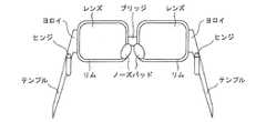
また、本明細書における表示状態切替用眼鏡を構成する部位を図11に基づいて説明しておく。図11に示すように、レンズの周りを囲む縁の部位をリム、左右の2つのリムをつなぐ部位をブリッジ、視聴者の耳に接触して顔を挟み込む部位をテンプル、テンプルの開閉を担う部位をヒンジ、リムからヒンジまでの部位をヨロイ、及び、鼻と接触し眼鏡を支える固定する部位をノーズパッドとして、本明細書では記載している。 Further, the parts constituting the display state switching glasses in this specification will be described with reference to FIG. As shown in FIG. 11, the rim part surrounding the lens is a rim, the part connecting the two left and right rims is bridged, the part that touches the viewer's ear and sandwiches the face is the temple, and the part responsible for opening and closing the temple In the present specification, the part from the rim to the hinge is defined as a hinge, and the part that contacts the nose and supports the glasses is defined as a nose pad.
そして、本発明の上記構成によれば、表示状態切替用眼鏡の着用時に、電源が表示状態切替機構を動作させ得るスタンバイ状態にあることを、認識手段によって視聴者が認識することができる。それにより、視聴者が立体映像を視聴する際、または、1つの表示装置にて複数人の視聴者がそれぞれの視聴者向けの個別の映像を視聴する際に生じる、表示状態切替用眼鏡を正しく動作させて、立体映像またはそれぞれの視聴者向けの個別の映像を視聴できているかどうかという不安感を低減することができる。 And according to the said structure of this invention, a viewer can recognize that a power supply is in the standby state which can operate a display state switching mechanism at the time of wearing of the display state switching glasses. As a result, the display state switching glasses that are generated when a viewer views a stereoscopic video or when a plurality of viewers view individual videos for each viewer on a single display device are correctly set. By operating, it is possible to reduce anxiety about whether or not a stereoscopic video or individual video for each viewer can be viewed.
また、テンプルが開かれることで、上記電源を上記スタンバイ状態とする第1電源制御手段を備えていることが望ましい。 Moreover, it is desirable to have first power control means for setting the power to the standby state by opening the temple.
上記構成によれば、テンプルが開かれることで、電源をスタンバイ状態にする第1電源制御手段を備えている。そのため、表示状態切替用眼鏡の着用動作に伴うテンプルを開くという動作により、第1電源制御手段が確実に電源をスタンバイ状態にすることができる。 According to the above configuration, the first power supply control means for setting the power supply to the standby state by opening the temple is provided. Therefore, the first power supply control unit can reliably put the power supply in the standby state by the operation of opening the temple associated with the wearing operation of the display state switching glasses.
また、テンプルが着用準備位置から更に開かれることで、上記電源を上記スタンバイ状態とする第2電源制御手段を備えていることが望ましい。 Moreover, it is desirable to provide the 2nd power supply control means which makes the said power supply the said standby state by further opening a temple from a wearing preparation position.
上記構成によれば、テンプルが着用準備位置から更に開かれることで、電源をスタンバイ状態とする第2電源制御手段を備えている。そのため、表示状態切替用眼鏡の着用動作に伴うテンプルを更に開くという動作により、第2電源制御手段が確実に電源をスタンバイ状態にすることができる。 According to the said structure, the 2nd power supply control means which makes a power supply a standby state is provided by the temple being further opened from a wearing preparation position. Therefore, the operation of further opening the temple associated with the wearing operation of the display state switching glasses enables the second power supply control unit to reliably put the power supply in the standby state.
また、テンプルを更に開くという動作から電源をスタンバイ状態にしたという連想が伴い、表示状態切替用眼鏡を正しく動作させて立体映像、または、それぞれの視聴者向けの個別の映像を視聴できているという安心感を視聴者に与えることができる。 In addition, there is an association that the power supply was set to the standby state from the operation of further opening the temple, and the display state switching glasses were correctly operated to view the stereoscopic video or individual videos for each viewer. A sense of security can be given to the viewer.
また、上記第2電源制御手段は、上記テンプルが、上記着用準備位置あるいは当該着用準備位置よりも閉じられた位置である場合、上記電源を上記表示状態切替機構を動作させ得ない休止状態とすることが望ましい。 The second power supply control means sets the power supply to a resting state in which the display state switching mechanism cannot be operated when the temple is in the wearing preparation position or a position closed from the wearing preparation position. It is desirable.
上記構成によれば、第2電源制御手段は、テンプルが着用準備位置あるいは着用準備位置よりも閉じられた位置である場合、電源を休止状態とする。そのため、視聴者が表示状態切替用眼鏡を外し、テンプルが着用準備位置に戻ったこと、あるいは着用準備位置よりも閉じられた位置にテンプルがあることにより、第2電源制御手段が電源を休止状態として、消費電力を低減できる。 According to the said structure, a 2nd power supply control means makes a power supply a dormant state, when a temple is a wearing preparation position or the position closed rather than the wearing preparation position. Therefore, when the viewer removes the display state switching glasses and the temple returns to the wearing preparation position, or the temple is in a position closed from the wearing preparation position, the second power supply control means is in a power-off state. As a result, power consumption can be reduced.
また、ノーズパッドが鼻に接触したことで、上記電源を上記スタンバイ状態とする第3電源制御手段を備えていることが望ましい。 In addition, it is desirable to include third power supply control means for setting the power supply to the standby state when the nose pad contacts the nose.
上記構成によれば、ノーズパッドが鼻に接触したことで電源をスタンバイ状態とする第3電源制御手段を備えている。そのため、表示状態切替用眼鏡の着用動作に伴いノーズパッドが鼻に当たっていることにより、第3電源制御手段が確実に電源をスタンバイ状態にすることができる。また、視聴者は、表示状態切替用眼鏡の着用時に常に感じられるノーズパッドの感触から、電源のスタンバイ状態を常に確認でき、表示状態切替用眼鏡を正しく動作させて立体映像、または、それぞれの視聴者向けの個別の映像を視聴できているという安心感を得ることができる。 According to the said structure, the 3rd power supply control means which sets a power supply to a standby state because the nose pad contacted the nose is provided. Therefore, the third power supply control means can surely put the power supply in the standby state by the nose pad hitting the nose with the wearing operation of the display state switching glasses. In addition, the viewer can always check the standby state of the power supply from the feel of the nose pad that is always felt when wearing the display state switching glasses, and the display state switching glasses can be operated correctly to display the 3D images or the respective viewing images. You can get a sense of security that you can watch individual videos for the user.
また、上記第3電源制御手段は、上記ノーズパッドが鼻に接触していない場合、上記電源を上記表示状態切替機構を動作させ得ない休止状態とすることが望ましい。 Further, it is desirable that the third power source control means puts the power source into a resting state where the display state switching mechanism cannot be operated when the nose pad is not in contact with the nose.
上記構成によれば、第3電源制御手段は、ノーズパッドが鼻に接触していない場合、電源を休止状態とする。そのため、視聴者が表示状態切替用眼鏡を外してノーズパッドが鼻と接触しなくなったことを第3電源制御手段に検知させることで、電源を休止状態とし、消費電力を低減できる。 According to the said structure, a 3rd power supply control means makes a power supply a dormant state, when a nose pad is not contacting the nose. Therefore, by removing the display state switching glasses and causing the third power supply control means to detect that the nose pad is no longer in contact with the nose, the power supply can be put into a sleep state and power consumption can be reduced.
また、視聴者の体温を検知することで、上記電源を上記スタンバイ状態とする第4電源制御手段を備えていることが望ましい。 In addition, it is desirable to include fourth power control means for detecting the body temperature of the viewer so that the power source is in the standby state.
上記構成によれば、視聴者の体温を検知することで電源をスタンバイ状態とする第4電源制御手段を備えている。そのため、視聴者の表示状態切替用眼鏡の着用動作に伴い、視聴者の体温を第4電源制御手段に検知させることで、確実に電源をスタンバイ状態にすることができる。なお、視聴者の体温の検知は、公知の体温センサを用いて行うことが可能である。 According to the said structure, the 4th power supply control means which sets a power supply in a standby state by detecting a viewer's body temperature is provided. Therefore, the power supply can be surely brought into the standby state by causing the fourth power control means to detect the body temperature of the viewer in accordance with the wearing operation of the display state switching glasses by the viewer. Note that the viewer's body temperature can be detected using a known body temperature sensor.
また、上記第4電源制御手段は、視聴者の体温を検知していない場合、上記電源を上記表示状態切替機構を動作させ得ない休止状態とすることが望ましい。 Further, it is desirable that the fourth power source control means puts the power source into a resting state in which the display state switching mechanism cannot be operated when the body temperature of the viewer is not detected.
上記構成によれば、第4電源制御手段は、視聴者の体温を検知していない場合、電源を休止状態とするので、消費電力を低減できる。 According to the above configuration, the fourth power supply control unit puts the power supply into the sleep state when the body temperature of the viewer is not detected, so that power consumption can be reduced.
また、視聴者の血流を検知することで、上記電源を上記スタンバイ状態とする第5電源制御手段を備えていることが望ましい。 In addition, it is desirable to include a fifth power supply control means for setting the power supply to the standby state by detecting the blood flow of the viewer.
上記構成によれば、視聴者の血流を検知することで電源をスタンバイ状態とする第5電源制御手段を備えている。そのため、視聴者の表示状態切替用眼鏡の着用動作に伴い、視聴者の血流を第5電源制御手段に検知させることで、確実に電源をスタンバイ状態にすることができる。なお、視聴者の血流の検知は、公知の血流センサを用いて行うことができる。 According to the said structure, the 5th power supply control means which sets a power supply to a standby state by detecting a viewer's blood flow is provided. Therefore, the power supply can be reliably set to the standby state by causing the fifth power supply control means to detect the blood flow of the viewer in accordance with the wearing operation of the display state switching glasses. The viewer's blood flow can be detected using a known blood flow sensor.
また、上記第5電源制御手段は、視聴者の血流を検知していない場合、上記電源を上記表示状態切替機構を動作させ得ない休止状態とすることが望ましい。 Further, it is desirable that the fifth power supply control means sets the power supply to a resting state in which the display state switching mechanism cannot be operated when the viewer's blood flow is not detected.
上記構成によれば、第5電源制御手段は、視聴者の血流を検知していない場合、電源を休止状態とするので、消費電力を低減できる。 According to the above configuration, since the fifth power supply control unit puts the power supply into the sleep state when the viewer's blood flow is not detected, the power consumption can be reduced.
また、上記認識手段は、上記電源が上記スタンバイ状態である場合に、上記表示状態切替用眼鏡のレンズのいずれかの位置に、上記電源が上記スタンバイ状態であることを表示するものであることが望ましい。 The recognizing means may display that the power source is in the standby state at any position of the lens of the display state switching glasses when the power source is in the standby state. desirable.
上記構成によれば、表示状態切替用眼鏡の着用時に、電源がスタンバイ状態にあることを、視聴者が表示状態切替用眼鏡のレンズのいずれかの位置に目視認識することができる。それにより、視聴者が立体映像、または、それぞれの視聴者向けの個別の映像を視聴する際に生じる、表示状態切替用眼鏡を正しく動作させて、立体映像またはそれぞれの視聴者向けの個別の映像を視聴できているかどうかという不安感を低減することができる。更に、電源がスタンバイ状態か否かの確認時に視線をずらす必要がなく簡便である。 According to the above configuration, when the display state switching glasses are worn, the viewer can visually recognize at any position of the lens of the display state switching glasses that the power source is in the standby state. As a result, when the viewer views the stereoscopic video or the individual video for each viewer, the display state switching glasses are operated correctly so that the stereoscopic video or the individual video for each viewer is operated. Anxiety about whether or not you can watch Furthermore, it is not necessary to shift the line of sight when confirming whether the power supply is in a standby state, which is convenient.
本発明に係る表示状態切替用眼鏡は、以上のように、表示状態切替用眼鏡の着用時に、電源が表示状態切替機構を動作させ得るスタンバイ状態にあることを、認識手段によって視聴者が認識することができるという効果を奏する。それにより、視聴者が立体映像を視聴する際、または、1つの表示装置にて2人の視聴者がそれぞれの視聴者向けの個別の映像を視聴する際に生じる、表示状態切替用眼鏡を正しく動作させて、立体映像またはそれぞれの視聴者向けの個別の映像を視聴できているかどうかという不安感を低減することができるという効果を奏する。 In the display state switching glasses according to the present invention, as described above, when the display state switching glasses are worn, the viewer recognizes that the power supply is in a standby state in which the display state switching mechanism can be operated. There is an effect that can be. As a result, the display state switching glasses that are generated when a viewer views a stereoscopic video or when two viewers view individual videos for each viewer on a single display device are correctly displayed. It is possible to reduce the anxiety of whether or not a stereoscopic video or individual video for each viewer can be viewed by operating.
本発明の実施形態について図1〜図10に基づいて説明すれば、以下のとおりである。説明の便宜上、図面に示した部材と同一の機能を有する部材については、同一の符号を付し、その説明を省略する。 The embodiment of the present invention will be described below with reference to FIGS. For convenience of explanation, members having the same functions as those shown in the drawings are denoted by the same reference numerals, and description thereof is omitted.
〔1.テンプルを用いた認識例1〕
図1に基づき、本発明の一実施形態に係る表示状態切替用眼鏡の構成について説明する。図1は、表示状態切替用眼鏡の構成を示す構成図である。[1. Recognition example 1 using temples]
Based on FIG. 1, the structure of the display state switching glasses according to an embodiment of the present invention will be described. FIG. 1 is a configuration diagram illustrating a configuration of display state switching glasses.
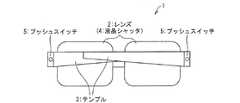
図1に示すように、表示状態切替用眼鏡1は、左右のレンズ2と、左右のテンプル3(認識手段)と、表示装置に表示される映像を視聴者に対して表示状態と非表示状態とに切り替える液晶シャッタ4(表示状態切替機構)と、を有している。 As shown in FIG. 1, the display state switching glasses 1 include a left and
上記構成の表示状態切替用眼鏡1を用いて、立体映像、または、それぞれの視聴者向けの個別の映像を視聴するにあたっては、まず、表示状態切替用眼鏡の液晶シャッタを動作させるための液晶シャッタ用電源(図示せず)を、液晶シャッタを動作させ得るスタンバイ状態とする必要がある。この点、上記構成の表示状態切替用眼鏡1においては、視聴者が表示状態切替用眼鏡1のテンプル3を開くと、それを表示状態切替用眼鏡1に設けられたプッシュスイッチ5が連動してスイッチON状態になることにより、このスタンバイ状態が実現される。 In viewing stereoscopic images or individual videos for each viewer using the display state switching glasses 1 having the above configuration, first, a liquid crystal shutter for operating the liquid crystal shutters of the display state switching glasses. The power supply (not shown) needs to be in a standby state in which the liquid crystal shutter can be operated. In this regard, in the display state switching glasses 1 configured as described above, when the viewer opens the
ここで、図1のプッシュスイッチ5周りの拡大図である図2を用い、スタンバイ状態が実現される様子について、より具体的に説明する。図2に示すように、テンプル3を図中矢印方向に開くことで、ヨロイ接触面に設けられたプッシュスイッチ5(第1電源制御手段)がテンプル接触面に押し込まれ、液晶シャッタ用電源がスタンバイ状態となる。本実施形態では、テンプル3がヨロイに設けられたプッシュスイッチ5を押すことについて記載しているが、テンプル3が開かれることで動作し、液晶シャッタ用電源をスタンバイ状態にでき、小型、軽量、人体に対して安全で眼鏡に搭載できる電源制御手段であれば、プッシュスイッチ5をそのような電源制御手段により置換しても構わない。加えて、上述した電源制御手段を設ける位置はヨロイに限定されず、例えばテンプルであっても構わない。 Here, referring to FIG. 2 which is an enlarged view around the push switch 5 of FIG. As shown in FIG. 2, by opening the
なお、テンプル3が閉じている状態において、プッシュスイッチ5がヨロイ接触面から飛び出している高さを調節することで、テンプル3をどれだけ開いた段階で液晶シャッタ用電源をスタンバイ状態にするかを調節することが可能である。また、このようなプッシュスイッチ5の高さ調節を、表示状態切替用眼鏡1の視聴者別に行うことも可能である。 When the
そして、液晶シャッタ用電源がスタンバイ状態となった後、立体映像を視聴者に対して表示する場合は、表示装置上に左右の目の視差を利用した視差映像が表示されると、その視差映像の表示に同期して、表示状態切替用眼鏡1の左右の液晶シャッタ4が開閉する。これにより、視聴者は視差映像を立体映像として視聴できる。 Then, when displaying the stereoscopic video to the viewer after the liquid crystal shutter power supply is in the standby state, when the parallax video using the parallax of the left and right eyes is displayed on the display device, the parallax video is displayed. In synchronization with this display, the left and right
また、1つの表示装置で複数の視聴者に異なった映像を見せる場合、例えば、視聴者Aにa1,a2,a3,…という視聴者A用映像を順番にフレーム毎に見せ、視聴者Bにb1,b2,b3,…という視聴者B用映像を順番にフレーム毎に見せる場合を想定する。この場合、表示装置上にa1,b1,a2,b2,a3,b3,…という順に、視聴者A用映像と視聴者B用映像とを交互に切り替えて表示する。 Further, when different videos are shown to a plurality of viewers on one display device, for example, the viewer A videos such as a1, a2, a3,... Assume that viewer B videos such as b1, b2, b3,... are sequentially displayed for each frame. In this case, the viewer A video and the viewer B video are alternately switched and displayed on the display device in the order of a1, b1, a2, b2, a3, b3,.
そして、この視聴者A用映像と視聴者B用映像との表示切替に同期して、視聴者毎に対応したタイミングで、表示状態切替用眼鏡1の液晶シャッタ4を開閉する。つまり、視聴者Aが用いる表示状態切替用眼鏡の液晶シャッタは、視聴者A用映像a1,a2,a3,…の時に開き、視聴者B用映像b1,b2,b3,…の時に閉じる。これにより、視聴者毎に異なった映像を視聴することができる。 Then, in synchronization with the display switching between the viewer A video and the viewer B video, the
上記構成によれば、プッシュスイッチ5は、表示状態切替用眼鏡1の着用時にテンプル3が開かれることに連動してスイッチON状態になることで、液晶シャッタ用電源をスタンバイ状態にする。つまり、テンプル3を開くという動作が、液晶シャッタ用電源がスタンバイ状態になったという連想に繋がることで、視聴者がスタンバイ状態を認識することができる。この点において、テンプル3は、液晶シャッタ用電源がスタンバイ状態にあることを視聴者に認識させる認識手段として機能しているといえる。 According to the above configuration, the push switch 5 switches the power supply for the liquid crystal shutter to the standby state by being switched on in conjunction with the opening of the
そして、上述の連想を発生させることで、視聴者が立体映像を視聴する際、または、1つの表示装置にて2人の視聴者がそれぞれの視聴者向けの個別の映像を視聴する際に生じる、表示状態切替用眼鏡1を正しく動作させて、立体映像またはそれぞれの視聴者向けの個別の映像を視聴できているかどうかという不安感を低減することができる。その上、表示状態切替用眼鏡1の着用動作に伴うテンプル3を開くという動作によって、確実に液晶シャッタ用電源をスタンバイ状態にすることができる。 Then, by generating the association described above, it occurs when a viewer views a stereoscopic video, or when two viewers view individual videos for each viewer on one display device. Thus, the display state switching glasses 1 can be operated correctly to reduce anxiety about whether or not a stereoscopic video or individual video for each viewer can be viewed. Moreover, the power supply for the liquid crystal shutter can be surely brought into the standby state by the operation of opening the
〔2.テンプルを用いた認識例2〕
次に、本発明の他の実施形態として、テンプルが着用準備位置から更に開かれることで液晶シャッタ用電源をスタンバイ状態とする表示状態切替用眼鏡10について、液晶シャッタ用電源のスタンバイ状態を視聴者に認識させるための構成を説明する。[2. Example 2 of recognition using temples]
Next, as another embodiment of the present invention, with respect to the display
図3に示すように、表示状態切替用眼鏡10は、ヨロイに圧電素子11が設けられている。この圧電素子11は、表示状態切替用眼鏡10のテンプル3が着用準備位置から更に開かれることで加わる応力によって、電位差を発生させるものである。 As shown in FIG. 3, the display
ここで、テンプル3の位置を図4に基づいて説明する。図4に示すように、テンプル3の「着用準備位置」とはヒンジが最大角に開き、かつ、表示状態切替用眼鏡10にテンプルの開閉方向に力がかかっていない位置である。なお、テンプル3が着用準備位置にある場合の左右のテンプル3の先端同士の距離をXとする。左右のテンプル3の先端同士の距離がXより大きくなると、表示状態切替用眼鏡10、中でもテンプル3及びヨロイに力がかかり、テンプル3が閉じる方向へ力がかかる。また、「着用位置」とは視聴者が表示状態切替用眼鏡10を着用しているときの位置であり、「着用時最大開き位置」とは視聴者が表示状態切替用眼鏡10を着用するときに最も左右のテンプル3の先端同士の距離が大きくなる位置である。なお、テンプル3が着用位置、または、着用時最大開き位置にある場合、左右のテンプル3の先端同士の距離をそれぞれY、Zとすると、X<Y<Zとなる。つまり、表示状態切替用眼鏡10の着用時には、まず着用準備位置にテンプル3を開く。そして、顔にぶつからないように更にもう少しテンプル3を着用時最大開き位置まで開いて、テンプル3を顔の側面を通り後方に向けて移動させる。なお、この着用準備位置から着用時最大開き位置までテンプル3を開いていく過程において、テンプル3には、着用準備位置まで閉じる方向へ戻ろうとする力がかかっている。 Here, the position of the
そして最後に、テンプル3を耳に掛けながら手を離すが、それによりテンプル3は着用時最大開き位置から着用位置までやや閉じる。この着用時においてテンプル3が開いている状態としては、表示状態切替用眼鏡10が視聴者の顔にフィットしていればよい。そのようにフィットする状態とは、着用準備位置よりややテンプル3が開いた状態、つまりテンプル3が閉じる方向へ戻ろうとする力が幾分かかった状態である。 Finally, the hand is released while putting the
そして、表示状態切替用眼鏡10は、テンプル3が着用準備位置からさらに開かれることで圧電素子11に生じる電位差により、液晶シャッタ用電源をスタンバイ状態とする。すなわち、圧電素子11は、テンプル3が着用準備位置から更に開かれることで、液晶シャッタ用電源をスタンバイ状態とする第2電源制御手段として機能している。ここで、電位差により液晶シャッタ用電源をスタンバイ状態とするには、例えば公知のスイッチ動作をするトランジスタを用いることが挙げられる。なお、圧電素子11を設ける位置はヨロイに限定されず、テンプル3が着用準備位置から更に開かれることで応力が加わる位置であればよく、例えばブリッジであっても構わない。 The display
上記構成によれば、表示状態切替用眼鏡10の着用時に、テンプル3を着用準備位置から更に開くという動作に伴い、圧電素子11に生じる電位差がセンサにより検知され、それをトリガとして液晶シャッタ用電源がスタンバイ状態となる。換言すれば、視聴者の立場では、テンプル3を更に開くという動作から液晶シャッタ用電源をスタンバイ状態にしたという連想が伴う。この点において、テンプル3は、液晶シャッタ用電源がスタンバイ状態にあることを視聴者に認識させる認識手段として機能しているといえる。 According to the above configuration, when the display
そして、上述の連想を発生させることで、表示状態切替用眼鏡10を正しく動作させて立体映像、または、それぞれの視聴者向けの個別の映像を視聴できているという安心感を視聴者に与えることができる。 Then, by generating the association described above, it is possible to give the viewer a sense of security that the display
その上、表示状態切替用眼鏡10の着用動作に伴うテンプル3を更に開くという動作によって、確実に液晶シャッタ用電源をスタンバイ状態にすることができる。 In addition, the power supply for the liquid crystal shutter can be surely brought into the standby state by the operation of further opening the
さらに、液晶シャッタ用電源がスタンバイ状態であることを視聴者により確実に認識させるため、テンプル3が着用準備位置から更に開かれる場合に、ノッチ音が発生するようにテンプル3のヒンジを構成してもよい。このようにノッチ音が発生するようにしておけば、ノッチ音によっても、液晶シャッタ用電源がスタンバイ状態になったことを視聴者に認識させることができる。 Further, in order to ensure that the viewer can recognize that the power supply for the liquid crystal shutter is in the standby state, the hinge of the
また、テンプル3が、着用準備位置あるいは着用準備位置よりも閉じられた位置である場合、液晶シャッタ用電源を液晶シャッタ4を動作させ得ない休止状態としてもよい。これは、圧電素子11での電位差が発生していない場合に、液晶シャッタ用電源を休止状態とすることで実現できる。 Further, when the
上記構成によれば、第2電源制御手段である圧電素子11は、テンプル3が着用準備位置あるいは着用準備位置よりも閉じられた位置である場合、圧電素子11において電位差が0となり、液晶シャッタ用電源を休止状態とする。そのため、視聴者が表示状態切替用眼鏡10を外し、テンプル3が着用準備位置に戻ったこと、あるいは着用準備位置よりも閉じられた位置にテンプル3があることで、圧電素子11において電位差が0となり、液晶シャッタ用電源を休止状態として、消費電力を低減できる。 According to the above configuration, when the
〔3.ノーズパッドによる認識例〕
また、ノーズパッドを用いて、液晶シャッタ用電源がスタンバイ状態になったことを視聴者に認識させることも可能であるので、本発明のさらに他の実施形態として以下に説明する。[3. Example of recognition by nose pad)
In addition, since it is possible to make the viewer recognize that the power supply for the liquid crystal shutter is in a standby state using a nose pad, this will be described below as still another embodiment of the present invention.
すなわち、図5に示すように、表示状態切替用眼鏡20に設けられたノーズパッド21に圧電素子22を設ける。そして、視聴者が表示状態切替用眼鏡20を着用する時、ノーズパッド21に鼻からの応力がかかることにより圧電素子22に電位差が生じるので、この電位差を、液晶シャッタ用電源をスタンバイ状態とするためのトリガとすることができる。すなわち、圧電素子22は、ノーズパッド21に応力がかかることを検知することで、液晶シャッタ用電源をスタンバイ状態とする第3電源制御手段として機能している。 That is, as shown in FIG. 5, the piezoelectric element 22 is provided on the
上記構成によれば、表示状態切替用眼鏡20の着用時に、ノーズパッド21に鼻からの応力がかかることにより圧電素子22に電位差が生じ、これをトリガとして液晶シャッタ用電源がスタンバイ状態となる。視聴者の立場で言い換えれば、液晶シャッタ用電源がスタンバイ状態にあることを、ノーズパッド21の鼻への接触によって認識することができる。この点において、ノーズパッド21は、液晶シャッタ用電源がスタンバイ状態にあることを視聴者に認識させる認識手段として機能しているといえる。 According to the above configuration, when the display
そして、上述の連想を発生させることで、視聴者が立体映像、または、それぞれの視聴者向けの個別の映像を視聴する際に生じる、表示状態切替用眼鏡20を正しく動作させて立体映像を視聴できているかどうかという不安感を低減することができる。その上、表示状態切替用眼鏡20の着用動作に伴うノーズパッド21を鼻に当てるという動きによって、確実に液晶シャッタ用電源をスタンバイ状態にすることができる。 Then, by generating the association described above, the viewer can view the stereoscopic video by correctly operating the display
また、視聴者は、表示状態切替用眼鏡20の着用時に常に感じられるノーズパッド21の感触から、液晶シャッタ用電源のスタンバイ状態を常に確認でき、表示状態切替用眼鏡20を正しく動作させて立体映像、または、それぞれの視聴者向けの個別の映像を視聴できているという安心感を得ることができる。 In addition, the viewer can always check the standby state of the power supply for the liquid crystal shutter from the feel of the
また、ノーズパッド21が鼻に接触していない場合、液晶シャッタ用電源を液晶シャッタ4を動作させ得ない休止状態としてもよい。これは、ノーズパッド21が鼻に接触していない場合、つまり、圧電素子22での電位差が0である場合、液晶シャッタ用電源を休止状態とすることで実現可能である。これにより、液晶シャッタ用電源を適宜休止状態とし、消費電力を低減できる。 Further, when the
〔4.体温センサによる電源制御〕
また、図6に示すように、表示状態切替用眼鏡30に設けられた体温センサ31を用いて、液晶シャッタ用電源の制御を行うことも可能であるので、本発明の更に他の実施形態として以下に説明する。[4. (Power control by body temperature sensor)
Further, as shown in FIG. 6, it is also possible to control the power supply for the liquid crystal shutter using the body temperature sensor 31 provided in the display
表示状態切替用眼鏡30に設けられる体温センサ31として、熱電対が用いられる。熱電対の一端は、表示状態切替用眼鏡30の身体への接触部として、たとえばテンプルに設けられる。また、熱電対の他端は、表示状態切替用眼鏡30における視聴者の身体への非接触部として、たとえばヨロイに設けられる。 A thermocouple is used as the body temperature sensor 31 provided in the display
このように、熱電対の両端を身体への接触部および非接触部のそれぞれに設けることで、熱電対の両端で温度差が生じるので、熱電対に電位差が生じる。そして、このように熱電対に生じる電位差を、液晶シャッタ用電源をスタンバイ状態にするためのトリガとしてもよい。すなわち、体温センサ31を、視聴者の体温を検知することで、液晶シャッタ用電源をスタンバイ状態とする第4電源制御手段として機能させてもよい。 Thus, by providing both ends of the thermocouple at each of the contact portion and the non-contact portion with respect to the body, a temperature difference is generated at both ends of the thermocouple, so that a potential difference is generated in the thermocouple. The potential difference generated in the thermocouple as described above may be used as a trigger for setting the liquid crystal shutter power supply to the standby state. That is, the body temperature sensor 31 may function as a fourth power control unit that detects the viewer's body temperature to place the liquid crystal shutter power supply in a standby state.
ここで、体温センサ31の具体的な構成について図7を用いて説明する。図7に示すように、熱電対で生じた電位差によって、熱電対に電気的に接続されたコイルに電流が流れ、コイル内に磁界が発生する。そして、コイル内のスイッチ部材(磁石)が磁力によって移動することで、液晶シャッタ電源はスタンバイ状態となる。 Here, a specific configuration of the body temperature sensor 31 will be described with reference to FIG. As shown in FIG. 7, due to the potential difference generated in the thermocouple, a current flows through the coil electrically connected to the thermocouple, and a magnetic field is generated in the coil. The switch member (magnet) in the coil is moved by the magnetic force, so that the liquid crystal shutter power supply is in a standby state.
なお、熱電対の一端が設けられる接触部は、テンプルに限定されるものではない。たとえば、ノーズパッドに熱電対の一端を設けてもよい。また、熱電対の他端が設けられる非接触部は、ヨロイに限定されるものではない。たとえば、レンズのリムに熱電対の他端を設けてもよい。 The contact portion where one end of the thermocouple is provided is not limited to the temple. For example, one end of a thermocouple may be provided on the nose pad. Moreover, the non-contact part in which the other end of a thermocouple is provided is not limited to Yoroi. For example, the other end of the thermocouple may be provided on the rim of the lens.
上記構成によれば、表示状態切替用眼鏡30の着用時に、体温センサ31により視聴者の体温を検知し、液晶シャッタ用電源をスタンバイ状態にする。言い換えれば、液晶シャッタ用電源がスタンバイ状態であることを、表示状態切替用眼鏡30の着用時に体温センサ31が設けられた表示状態切替用眼鏡30の部位(身体への接触部)が自身に触れることによって、視聴者は認識することができる。この点、体温センサ31が設けられた表示状態切替用眼鏡30の部位が、液晶シャッタ用電源がスタンバイ状態にあることを視聴者に認識させる認識手段として機能しているといえる。 According to the above configuration, when the display
そして、そのようにスタンバイ状態を認識させることで、視聴者が立体映像、または、それぞれの視聴者向けの個別の映像を視聴する際に生じる、表示状態切替用眼鏡30を正しく動作させて立体映像、または、それぞれの視聴者向けの個別の映像を視聴できているかどうかという不安感を低減することができる。その上、表示状態切替用眼鏡30の着用動作に伴い、確実に液晶シャッタ用電源をスタンバイ状態にすることができる。 Then, by recognizing the standby state in this way, the viewer can correctly operate the display
また、視聴者の体温を体温センサ31が検知していない場合、液晶シャッタ用電源を液晶シャッタを動作させ得ない休止状態としてもよい。これにより、液晶シャッタ用電源を適宜休止状態として、消費電力を低減できる。 Further, when the body temperature sensor 31 does not detect the body temperature of the viewer, the liquid crystal shutter power source may be in a resting state in which the liquid crystal shutter cannot be operated. Thereby, the power consumption can be reduced by appropriately setting the power source for the liquid crystal shutter to a resting state.
〔5.血流センサによる電源制御〕
また、視聴者の血流を検知することにより液晶シャッタ用電源の制御を行うことも可能であるので、本発明のさらに他の実施形態として以下に説明する。[5. (Power control by blood flow sensor)
Further, since it is possible to control the power supply for the liquid crystal shutter by detecting the blood flow of the viewer, it will be described below as still another embodiment of the present invention.
視聴者の血流の検知は、図8に示すように、表示状態切替用眼鏡40のノーズパット21に血流センサ41を設けることにより実現可能である。なお、血流センサ41は、接触型のものであれば、テンプルをはじめとする表示状態切替用眼鏡40における身体への接触部分に設ければよい。また、血流センサ41が非接触型のものである場合、血流の検知精度を向上させるために、表示状態切替用眼鏡40においてなるべく身体に近い位置に血流センサを設ければよい。 As shown in FIG. 8, the blood flow of the viewer can be detected by providing a blood flow sensor 41 on the
そして、視聴者が表示状態切替用眼鏡40を着用する際、視聴者の血流を血流センサ41で検知する。そして、血流センサ41により視聴者の血流が検知されたことを、液晶シャッタ用電源をスタンバイ状態にするためのトリガとしてもよい。すなわち、血流センサ41を、視聴者の血流を検知することで、液晶シャッタ用電源をスタンバイ状態とする第5電源制御手段として機能させてもよい。 When the viewer wears the display
上記構成によれば、表示状態切替用眼鏡40の着用時に、血流センサ41で視聴者の血流を検知し、液晶シャッタ用電源をスタンバイ状態にする。言い換えれば、液晶シャッタ用電源がスタンバイ状態であることを、表示状態切替用眼鏡40の着用時に血流センサ41が設けられた表示状態切替用眼鏡40の部位が自身に触れることで、視聴者は液晶シャッタ用電源のスタンバイ状態を認識することができる。この点、血流センサ41が設けられた表示状態切替用眼鏡40の部位が、液晶シャッタ用電源がスタンバイ状態にあることを視聴者に認識させる認識手段として機能しているといえる。 According to the above configuration, when the display
そして、そのようにスタンバイ状態を認識させることで、視聴者が立体映像、または、それぞれの視聴者向けの個別の映像を視聴する際に生じる、表示状態切替用眼鏡40を正しく動作させて立体映像を視聴できているかどうかという不安感を低減することができる。その上、表示状態切替用眼鏡40の着用動作に伴い、確実に液晶シャッタ用電源をスタンバイ状態にすることができる。 Then, by recognizing the standby state in this way, the viewer can correctly operate the display
また、視聴者の血流を血流センサ41が検知していない場合、液晶シャッタ用電源を液晶シャッタ4を動作させ得ない休止状態としてもよい。これにより、液晶シャッタ用電源を適宜休止状態として、消費電力を低減できる。 Further, when the blood flow sensor 41 does not detect the blood flow of the viewer, the liquid crystal shutter power supply may be in a pause state in which the
〔6.インジケーターによる認識例〕
また、LED等のインジケーターを液晶シャッタ用電源がスタンバイ状態であることを視聴者に認識させる認識手段とすることも可能なので、本発明のさらに他の実施形態として以下に説明する。[6. (Example of indicator recognition)
Further, since an indicator such as an LED can be used as a recognition means for allowing the viewer to recognize that the power supply for the liquid crystal shutter is in a standby state, it will be described below as still another embodiment of the present invention.
すなわち、図9に示すように、液晶シャッタ用電源がスタンバイ状態である場合に、表示状態切替用眼鏡50のレンズのいずれかの位置に、液晶シャッタ用電源がスタンバイ状態であることをインジケーター51(認識手段)により表示する。 That is, as shown in FIG. 9, when the liquid crystal shutter power supply is in the standby state, the indicator 51 (indicating that the liquid crystal shutter power supply is in the standby state at any position of the lens of the display
なお、図9に記載されている“スイッチ”は、第1電源制御手段であるプッシュスイッチと同等の機能を有している。すなわち、図9に記載のスイッチは、表示状態切替用眼鏡50の着用時にテンプル3が開かれることに連動して、液晶シャッタ用電源をスタンバイ状態とするものである。そして、そのように液晶シャッタ用電源がスタンバイ状態になったことに連動して、インジケーター51を表示させればよい。ここで、図9に記載のスイッチは第1電源制御手段であるプッシュスイッチと同等の機能を有するスイッチに限定されるものではない。たとえば、図9に記載のスイッチを視聴者が手動にてスイッチON状態とすることで、液晶シャッタ用電源をスタンバイ状態にするプッシュスイッチであってもよい。さらに、図9に記載のスイッチを視聴者が手動にてスイッチON状態とすることで、液晶シャッタ用電源をスタンバイ状態にするプッシュスイッチである場合、図9に記載のスイッチを設ける位置はヨロイ接触面に限定されるものではなく、テンプル3やヨロイ接触面以外のヨロイに設けてもよい。 Note that the “switch” shown in FIG. 9 has the same function as the push switch as the first power supply control means. That is, the switch shown in FIG. 9 sets the power supply for the liquid crystal shutter in a standby state in conjunction with the opening of the
上記構成によれば、表示状態切替用眼鏡50の着用時に、液晶シャッタ用電源がスタンバイ状態にあることを、インジケーター51の表示によって視聴者が認識することができる。それにより、視聴者が立体映像を視聴する際に生じる、表示状態切替用眼鏡50を正しく動作させて立体映像、または、それぞれの視聴者向けの個別の映像を視聴できているかどうかという不安感を低減することができる。なお、表示状態切替用眼鏡50の電池残量が残り少ない場合には、インジケーター51を点滅させることにより視聴者に残量が少ない旨を知らせてもよい。 According to the above configuration, when the display
そして、インジケーター51を設ける位置は、視聴の妨げにならないことに加え、視線をずらさずとも視界の片隅に見える位置を選べばよい。そうであれば、液晶シャッタ用電源がスタンバイ状態か否かの確認時に視線をずらす必要がなく簡便である。 And the position which provides the indicator 51 should just select the position which can be seen in one corner of a visual field, without shifting a line of sight, in addition to not disturbing viewing. If so, there is no need to shift the line of sight when confirming whether or not the power supply for the liquid crystal shutter is in a standby state, which is simple.
なお、図1〜図9でレンズを左右二つに分けて描いているが、機能上に支障が無ければ図10に示すように左右一体型のレンズであってもよい。 1 to 9, the left and right lenses are depicted separately. However, as long as there is no functional problem, a left and right integrated lens may be used as shown in FIG.
〔7.無線電力供給〕
なお、表示状態切替用眼鏡の液晶シャッタ用電源に対する電力供給を、無線電力供給により行うことも可能である。無線電力供給を実現するためには、表示装置側に電力送電部を設ける一方、表示状態切替用眼鏡に受電部を設ける。送電部には、送電コイルと電源部とが設けられ、受電部には、受電コイルが設けられている。電源部から交流電流を送電コイルに供給することで、送電コイルと受電コイルとの間で磁界が振動し、共鳴現象が起こる所定の周波数を有する磁場を発生させることができる。そして、送電コイルで磁場を発生させ、送電コイルと受電コイルとの間で磁場を共鳴させることで、送電部から受電部へ電力を無線供給することができる。[7. Wireless power supply)
It is also possible to supply power to the liquid crystal shutter power supply of the display state switching glasses by wireless power supply. In order to realize wireless power supply, a power transmission unit is provided on the display device side, and a power reception unit is provided on the display state switching glasses. The power transmission unit is provided with a power transmission coil and a power supply unit, and the power reception unit is provided with a power reception coil. By supplying an alternating current from the power supply unit to the power transmission coil, the magnetic field is vibrated between the power transmission coil and the power reception coil, and a magnetic field having a predetermined frequency at which a resonance phenomenon occurs can be generated. Then, by generating a magnetic field with the power transmission coil and resonating the magnetic field between the power transmission coil and the power reception coil, it is possible to wirelessly supply power from the power transmission unit to the power reception unit.
上記構成によれば、表示状態切替用眼鏡の電池交換の回数が減ったり、不要になったり、物理的な電力配線が不要になることで視聴者の動きの制限が軽減されるといった、従来の視聴者の負担が軽減される。 According to the above configuration, the number of battery replacement of the display state switching glasses is reduced or unnecessary, and the limitation of the movement of the viewer is reduced by eliminating the need for physical power wiring. The burden on the viewer is reduced.
本発明の表示状態切替用眼鏡は、表示状態切替用眼鏡の着用時に、電源が表示状態切替機構を動作させ得るスタンバイ状態にあることを、認識手段によって視聴者が認識することができる。それにより、視聴者が立体映像を視聴する際、または、1つの表示装置にて2人の視聴者がそれぞれの視聴者向けの個別の映像を視聴する際に生じる、表示状態切替用眼鏡を正しく動作させて、立体映像またはそれぞれの視聴者向けの個別の映像を視聴できているかどうかという不安感を低減することができる。 In the display state switching glasses of the present invention, the viewer can recognize that the power supply is in a standby state in which the display state switching mechanism can be operated when the display state switching glasses are worn. As a result, the display state switching glasses that are generated when a viewer views a stereoscopic video or when two viewers view individual videos for each viewer on a single display device are correctly displayed. By operating, it is possible to reduce anxiety about whether or not a stereoscopic video or individual video for each viewer can be viewed.
1,10,20,30,40,50 表示状態切替用眼鏡
3 テンプル(認識手段)
21 ノーズパッド(認識手段)
51 インジケーター(認識手段)
4 液晶シャッタ(表示状態切替機構)
5 プッシュスイッチ(第1電源制御手段)
11 圧電素子(第2電源制御手段)
22 圧電素子(第3電源制御手段)
31 体温センサ(第4電源制御手段)
41 血流センサ(第5電源制御手段)1, 10, 20, 30, 40, 50 Display
21 Nose pad (recognition means)
51 Indicator (recognition means)
4. Liquid crystal shutter (display state switching mechanism)
5 Push switch (first power control means)
11 Piezoelectric element (second power supply control means)
22 Piezoelectric element (third power supply control means)
31 Body temperature sensor (fourth power supply control means)
41 Blood flow sensor (5th power supply control means)
Claims (3)
Translated fromJapanese上記表示状態切替用眼鏡の着用時に、上記表示状態切替機構を動作させるための電源が、上記表示状態切替機構を動作させ得るスタンバイ状態にあることを上記視聴者に認識させる認識手段と、
テンプルが着用準備位置から更に開かれることで、上記電源を上記スタンバイ状態とする電源制御手段と、を備え、
上記認識手段として、上記テンプルが着用準備位置から更に開かれる場合にノッチ音が発生するヒンジを備え、
上記ノッチ音の発生により、上記電源がスタンバイ状態になったことを上記視聴者に認識させることを特徴とする表示状態切替用眼鏡。In display state switching glasses having a display state switching mechanism that switches a video displayed on a display device between a display state and a non-display state for a viewer,
Recognizing means for recognizing the viewer that a power source for operating the display state switching mechanism is in a standby state in which the display state switching mechanism can be operated when wearing the display state switching glasses;
The temple is further opened from the wearing preparation position,and includes a power control means for setting the power to the standby state,
As the recognition means comprisesa hinges notch sound is generated when the temple is further opened from the wearer readyposition,
Display state switching glasses characterizedby causing the viewer to recognize that the power source is in a standby state due to the occurrence of the notch sound .
Priority Applications (1)
| Application Number | Priority Date | Filing Date | Title |
|---|---|---|---|
| JP2011010175AJP5636295B2 (en) | 2011-01-20 | 2011-01-20 | Display state switching glasses |
Applications Claiming Priority (1)
| Application Number | Priority Date | Filing Date | Title |
|---|---|---|---|
| JP2011010175AJP5636295B2 (en) | 2011-01-20 | 2011-01-20 | Display state switching glasses |
Publications (2)
| Publication Number | Publication Date |
|---|---|
| JP2012150358A JP2012150358A (en) | 2012-08-09 |
| JP5636295B2true JP5636295B2 (en) | 2014-12-03 |
Family
ID=46792646
Family Applications (1)
| Application Number | Title | Priority Date | Filing Date |
|---|---|---|---|
| JP2011010175AExpired - Fee RelatedJP5636295B2 (en) | 2011-01-20 | 2011-01-20 | Display state switching glasses |
Country Status (1)
| Country | Link |
|---|---|
| JP (1) | JP5636295B2 (en) |
Families Citing this family (1)
| Publication number | Priority date | Publication date | Assignee | Title |
|---|---|---|---|---|
| US20250143583A1 (en)* | 2022-04-06 | 2025-05-08 | Nippon Telegraph And Telephone Corporation | Body temperature measurement device |
Family Cites Families (8)
| Publication number | Priority date | Publication date | Assignee | Title |
|---|---|---|---|---|
| JPS57176019A (en)* | 1981-04-22 | 1982-10-29 | Hiroshi Ozeki | Spectacles generating percussion sound during opening and closure of bows |
| JPS58113913A (en)* | 1981-12-26 | 1983-07-07 | Seiko Epson Corp | glasses with display device |
| JPH0736342Y2 (en)* | 1989-07-21 | 1995-08-16 | 株式会社村井 | Eyeglass hinge |
| JP4183342B2 (en)* | 1999-08-13 | 2008-11-19 | Hoya株式会社 | glasses |
| US8934000B2 (en)* | 2008-01-29 | 2015-01-13 | Eastman Kodak Company | Switchable 2-D/3-D display system |
| JP2009244603A (en)* | 2008-03-31 | 2009-10-22 | Panasonic Corp | Electronic spectacles |
| JP2009247361A (en)* | 2008-04-01 | 2009-10-29 | Panasonic Corp | Living body detector and electronic device using the same |
| US20100182404A1 (en)* | 2008-12-05 | 2010-07-22 | Panasonic Corporation | Three dimensional video reproduction apparatus, three dimensional video reproduction system, three dimensional video reproduction method, and semiconductor device for three dimensional video reproduction |
- 2011
- 2011-01-20JPJP2011010175Apatent/JP5636295B2/ennot_activeExpired - Fee Related
Also Published As
| Publication number | Publication date |
|---|---|
| JP2012150358A (en) | 2012-08-09 |
Similar Documents
| Publication | Publication Date | Title |
|---|---|---|
| JP5148016B2 (en) | 3D image providing apparatus and method | |
| KR20110101944A (en) | 3D glasses, driving method of 3D glasses and 3D image providing system | |
| US20110298794A1 (en) | Circular polarized contact lenses and methods thereof | |
| JP5110182B2 (en) | Video display device | |
| KR20110114260A (en) | 3D display device and its GUI setting method, and 3D glasses | |
| US20130286163A1 (en) | 3d glasses | |
| KR102237238B1 (en) | Vision training device to improve fusion function | |
| KR20110089997A (en) | Display device, 3D image providing method and 3D image providing system | |
| JP2012085106A (en) | Image processing apparatus, image processing method, and program | |
| CN102668578A (en) | Image display device, visual aid, and three-dimensional image display system using those | |
| JP6196014B2 (en) | Shutter glasses equipment | |
| KR20110044080A (en) | Display apparatus, image display method, stereoscopic glasses and driving method thereof | |
| KR101203921B1 (en) | Information providing apparatus using an eye tracking and local based service | |
| KR101309705B1 (en) | Glasses and 3D image display system employing the same | |
| JP5636295B2 (en) | Display state switching glasses | |
| WO2012018409A1 (en) | Tilt compensation for stereoscopic visual displays | |
| JP2012010217A (en) | Eyeglasses and display system | |
| JP2011118133A (en) | Stereoscopic image display system | |
| WO2012026375A1 (en) | Stereoscopic display apparatus | |
| JP2011205481A (en) | Stereoscopic video viewing tool and stereoscopic video display system | |
| KR20110116509A (en) | 3D image viewing device and system | |
| CN202159188U (en) | Adjustable polarized type 3D-2D compatible 3D glasses | |
| CN103931178A (en) | 3D image shutter glasses | |
| KR101338238B1 (en) | Three dimensional image watching glasses comprising position adjusting member | |
| JP2012080376A (en) | Video display device |
Legal Events
| Date | Code | Title | Description |
|---|---|---|---|
| A621 | Written request for application examination | Free format text:JAPANESE INTERMEDIATE CODE: A621 Effective date:20131001 | |
| A131 | Notification of reasons for refusal | Free format text:JAPANESE INTERMEDIATE CODE: A131 Effective date:20140422 | |
| A977 | Report on retrieval | Free format text:JAPANESE INTERMEDIATE CODE: A971007 Effective date:20140423 | |
| A521 | Request for written amendment filed | Free format text:JAPANESE INTERMEDIATE CODE: A523 Effective date:20140619 | |
| A131 | Notification of reasons for refusal | Free format text:JAPANESE INTERMEDIATE CODE: A131 Effective date:20140715 | |
| A521 | Request for written amendment filed | Free format text:JAPANESE INTERMEDIATE CODE: A523 Effective date:20140912 | |
| A01 | Written decision to grant a patent or to grant a registration (utility model) | Free format text:JAPANESE INTERMEDIATE CODE: A01 Effective date:20141007 | |
| A61 | First payment of annual fees (during grant procedure) | Free format text:JAPANESE INTERMEDIATE CODE: A61 Effective date:20141020 | |
| LAPS | Cancellation because of no payment of annual fees |