JP5633756B2 - How to make lighting fixtures - Google Patents
How to make lighting fixturesDownload PDFInfo
- Publication number
- JP5633756B2 JP5633756B2JP2012164425AJP2012164425AJP5633756B2JP 5633756 B2JP5633756 B2JP 5633756B2JP 2012164425 AJP2012164425 AJP 2012164425AJP 2012164425 AJP2012164425 AJP 2012164425AJP 5633756 B2JP5633756 B2JP 5633756B2
- Authority
- JP
- Japan
- Prior art keywords
- socket
- bulb
- fluorescent
- lighting fixture
- control box
- Prior art date
- Legal status (The legal status is an assumption and is not a legal conclusion. Google has not performed a legal analysis and makes no representation as to the accuracy of the status listed.)
- Expired - Fee Related
Links
Images


Landscapes
- Fastening Of Light Sources Or Lamp Holders (AREA)
- Non-Portable Lighting Devices Or Systems Thereof (AREA)
Description
Translated fromJapaneseこの発明は、照明器具用のソケットだけを新たに用意して消費電力を大幅に削減できる照明器具を簡単かつ安価に製作できる方法に関する。The present invention relates to a method for easily and inexpensively manufacturing a lighting fixture that can greatly reduce power consumptionby newly preparing only a socket for the lighting fixture.
近年エネルギ資源の不足が世界的な問題となっているが、現実に電力不足が生じており、節電への要請は高い。勿論、節電はコスト面でも歓迎すべきことである。 In recent years, a shortage of energy resources has become a global problem, but power shortages have actually occurred, and demand for power saving is high. Of course, power saving should be welcome in terms of cost.
ところで、通常の工場やオフィス室内では、照明器具として長方形の所謂笠形反射板内に一本以上の直管形蛍光ランプを配置したものが用いられている。言うまでもなく直管形蛍光ランプの消費電力は大きく、安定器やグロー球も必要で、多数の笠型照明器具を設置することは極めて非経済的である。従来のこのような照明器具をLED電球または蛍光電球を用いたものに置き換えることができれば経済的であることは知られているが、既設の
照明器具を一挙に新たな省エネルギ形照明器具に交換するのもコスト的に負担が重く、かつ既設の電気配線や照明器具を廃棄するのも無駄が大きい。By the way, in a normal factory or office room, a lighting fixture in which one or more straight tube fluorescent lamps are arranged in a rectangular so-called shade-shaped reflector is used. Needless to say, the power consumption of the straight tube fluorescent lamp is large, a ballast and a glow bulb are required, and it is extremely uneconomical to install a large number of shade lamps. Although it is known that it would be economical to replace such conventional lighting fixtures with LED bulbs or fluorescent bulbs, existing lighting fixtures could be replaced with new energy-saving lighting fixtures all at once. This is also costly and wasteful to dispose of existing electrical wiring and lighting fixtures.
そこでこの発明の課題は、長方形笠型照明器具の設置位置並びに既設の電気配線を大きく変えることなく、簡単で安価な設計変更または改造工事により、LED電球または蛍光電球を取り付けることができるようにし、電力消費量を大きく削減して電気料金の節減を計ろうとすることである。 Therefore, an object of the present invention is to make it possible to attach an LED bulb or a fluorescent bulb by a simple and inexpensive design change or remodeling work without greatly changing the installation position of the rectangular shade type lighting fixture and the existing electric wiring, The goal is to reduce electricity consumption by greatly reducing power consumption.
上記の課題を解決するため、この発明においては、下面が開放した直方形コントロールボックスの両端部に取り付けられた直管形蛍光ランプ用ソケットと前記コントロールボックスの下面に取り付けられた笠形反射板より成る照明器具を用いて、前記蛍光ランプ用ソケットを取り外し、その個所に、LED電球または蛍光電球用口金を有するソケット本体の上面に前記コントロールボックスの両端部と係合する抜き差し係合手段を設けたLED電球または蛍光電球用ソケットを取り付ける方法を採用したのである。In order to solve the above problems, the present invention comprisesa straight fluorescent lamp socket attached to both ends of a rectangular control box having an open bottom surface and a shade-shaped reflector attached to the bottom surface of the control box. Using the lighting fixture, the fluorescent lamp socket is removed, and an LED engaging / disengaging means for engaging the both ends of the control box is provided on the upper surface of the socket body having the LED bulb or the fluorescent bulb base at the location. A method of attaching a socket for a light bulb or fluorescent bulb was adopted .
上記LED電球または蛍光電球用ソケットは抜き差し係合手段によって前記ボックスに着脱可能に取り付けるのが好ましい。さらに、電球の光の特性や指向性により、LED電球または蛍光電球用ソケットがやゝ下方に傾斜するように取り付けることもできる。 It is preferable that the socket for the LED bulb or the fluorescent bulb is detachably attached to the box by an insertion / extraction engagement means. Furthermore, the LED light bulb or the fluorescent light bulb socket can be attached so as to be inclined slightly downward depending on the light characteristics and directivity of the light bulb.
この発明によれば、以上のように、従来の直管形蛍光ランプ用ソケットに換えて、簡単に取り付けできるLED電球または蛍光電球用ソケットを用いたので、安定器やグロー球も不要となり大幅に消費電力量を削減することができ、また直管形蛍光ランプを用いた笠形照明器具に、天井からの電気配線に直接接続可能な機能を有する球形ランプ用ソケットを取り付ける簡単な改造だけで、この発明の照明器具を製作できるのでコスト面でも大きなメリットがある。According to the present invention, as described above,instead of the conventional straight tube type fluorescent lamp socket, the LED bulb or the fluorescent bulb socket that can be easily attached isused, so that a ballast and a glow bulb are not required, and the The power consumption can be reduced, and a simple lamp remodeling that attaches a spherical lamp socket with a function that can be directly connected to the electric wiring from the ceiling to a shade-shaped luminaire that uses a straight tube fluorescent lamp. Since the lighting apparatus of the invention can be manufactured, there is a great merit in terms of cost.
以下この発明の実施形態を添付図面に基づいて説明する。まず、照明器具の製作方法に用いるソケット10は、図1及び図2に示すように、LED電球や蛍光電球を挿し込むことができるらせん口金(E形)12を一体に設けた本体11と、本体11の上面に設けられた取付け用突起13より成る。これらの本体11と突起13は、例えば合成樹脂の一体成形によって形成されたものである。 Embodiments of the present invention will be described below with reference to the accompanying drawings. First, as shown in FIGS. 1 and 2, a
前記突起13は、図1(B)に示されるように、正面から見てほぼT字形になっており、両側に溝14、14が形成されている。また、口金12及び接点12aにつながるプラグ挿入口15が設けられている。この挿入口15に後述する配線接続用プラグ27が挿し込まれる。なお、プラグ挿入口15に換えて、単に口金12及び接点12aにつながるリード線が設けられたものでもよい。 As shown in FIG. 1B, the
図2にソケット10の変形例を示す。図示のように、口金12を有する本体11をやゝ下方に傾斜させることができる。これによって、LED電球または蛍光電球をやゝ下方に向けて傾斜させることができる。 FIG. 2 shows a modification of the
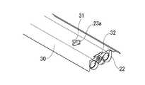
次に、上記のようなソケット10を従来の照明器具に取り付け、新たな照明器具を製作する方法について説明する。図3は従来の直管形蛍光ランプを装着した照明器具の一例を示す。従来の照明器具は、図示のように、天井内の適当な支持面Aに対してボルト・ナット等の固定手段Bにより固定される直方形のコントロールボックス20と、このボックス20に取り付けられる安定器21、21及びソケット22、22と、前記ボックス20の下面に取り付けられる笠形反射板30と、前記ソケット22、22に取り付けられる直管形蛍光ランプ40、40及びグローランプ41、41より成る。前記笠形反射板30は断面が台形または欠円形をなし、適当な手段によって前記ボックス20の下面に固定される。例えば図示の場合、ボックス20の下面に横バー23、23が固定され、それぞれの横バー23にラッチ23aが設けられ、図4に示すように反射板30に設けられた長孔31に挿し込んで係止できるようになっている。また、ボックス20には、その両端部の下面にフランジ24、24が設けられ、ソケット22の上端に設けられた突起25によってボックス20の両端部に取り付けることができるようになっている。また、反射板30の両端には凸状の切欠き32が設けられ、図4に示すように、反射板30をラッチ23aによってボックス20に取り付けたとき、ソケット22が反射板30内に突出するのを許容するようになっている。なお、ソケット22には、配線26がプラグ27によって接続されている。 Next, a method of manufacturing a new lighting fixture by attaching the
上記のような照明器具を次のような手順で改造して行く。まず蛍光ランプ40及びグローランプ41を取り外し、反射板30も取り外す。次いでソケット22をボックス20のフランジ24から取り外し、配線26との接続を外す。ソケット22と配線26がプラグ27で接続されていればプラグを抜くだけでよい。 The lighting fixture as described above is modified in the following procedure. First, the
上記直管形蛍光ランプ用ソケット22に換えて、図1または図2に示すような新たなソケット10を取り付ける。前述のように、このソケット10にはT字形突起13が設けられているので、図5に示すように、ボックス20の両端のフランジ24をT形突起13の両側の溝14に嵌め合せる。そしてプラグ挿入口15に配線26のプラグ27を挿し込んだ後、反射板30をボックス20に取り付ける。このとき、ソケット10の形状が従来のソケット22と異なり、反射板30の両端の凸形切欠き32が通過できない(引掛る)ことがある。その場合には、反射板30の両端部を切断したり、研削する等の方法でソケット10の形状に合致するような加工を施せばよい。その後、LED電球または蛍光電球をソケット10に挿し込めば照明器具が完成する。なお、新たな抜き差し係合手段によるソケット10の構造上その全長が少し長くなり従来の反射板30の切欠き32の形状では組立てに支障をきたすようであれば、切欠き32の形状を合致するようにした新たな反射板を用いればよい。 Instead of the straight tube type
また、コントロールボックス20には、安定器等の機器が装着されており、それらを取り除くのが困難な場合そのまま放置してもよいが、電気工事上の安全性などの観点から前記のような機器を装着していない新たなコントロールボックスを用いてもよい。 The
さらに反射板30の形状も笠形のみを示したが、両端部に端板を設けた箱形のものでもよい。その場合には端板に直接ソケットを取り付けることもできる。 Further, the shape of the
A 支持面
B 固定手段
10 ソケット
11 ソケット本体
12 口金
12a 接点
13 T形突起
14 溝
15 プラグ挿入口
20 コントロールボックス
21 安定器
22 ソケット
23 横バー
23a ラッチ
24 フランジ
25 突起
26 配線
27 プラグ
30 笠形反射板
31 長孔
32 凸形切欠き
40 直管形蛍光ランプ
41 グローランプA Support surface B Fixing means 10
Claims (2)
Translated fromJapanesePriority Applications (1)
| Application Number | Priority Date | Filing Date | Title |
|---|---|---|---|
| JP2012164425AJP5633756B2 (en) | 2012-07-25 | 2012-07-25 | How to make lighting fixtures |
Applications Claiming Priority (1)
| Application Number | Priority Date | Filing Date | Title |
|---|---|---|---|
| JP2012164425AJP5633756B2 (en) | 2012-07-25 | 2012-07-25 | How to make lighting fixtures |
Publications (2)
| Publication Number | Publication Date |
|---|---|
| JP2014026758A JP2014026758A (en) | 2014-02-06 |
| JP5633756B2true JP5633756B2 (en) | 2014-12-03 |
Family
ID=50200247
Family Applications (1)
| Application Number | Title | Priority Date | Filing Date |
|---|---|---|---|
| JP2012164425AExpired - Fee RelatedJP5633756B2 (en) | 2012-07-25 | 2012-07-25 | How to make lighting fixtures |
Country Status (1)
| Country | Link |
|---|---|
| JP (1) | JP5633756B2 (en) |
Family Cites Families (6)
| Publication number | Priority date | Publication date | Assignee | Title |
|---|---|---|---|---|
| JP2000222928A (en)* | 1999-01-29 | 2000-08-11 | Hitachi Lighting Ltd | Fluorescent lamp fixture |
| JP2005129233A (en)* | 2003-03-04 | 2005-05-19 | Ushio Spex Inc | Illumination fixture of separation structure |
| JP2011070810A (en)* | 2009-09-24 | 2011-04-07 | Panasonic Corp | Illumination light source |
| JP2012142242A (en)* | 2011-01-06 | 2012-07-26 | Adfuji Co Ltd | Base conversion adapter |
| JP5061303B1 (en)* | 2011-05-06 | 2012-10-31 | 今枝 伸行 | LED bulb holders mounted on fluorescent lamp fixtures |
| JP4835890B1 (en)* | 2011-06-03 | 2011-12-14 | 康裕 岩田 | Lighting equipment for fluorescent lighting fixtures |
- 2012
- 2012-07-25JPJP2012164425Apatent/JP5633756B2/ennot_activeExpired - Fee Related
Also Published As
| Publication number | Publication date |
|---|---|
| JP2014026758A (en) | 2014-02-06 |
Similar Documents
| Publication | Publication Date | Title |
|---|---|---|
| US7614769B2 (en) | LED conversion system for recessed lighting | |
| CN201377700Y (en) | LED module lamp | |
| US9726336B2 (en) | LED lighting system, lamp retrofit system, kit, and method | |
| KR200457978Y1 (en) | LED lighting | |
| CN202382128U (en) | LED down lamp structure | |
| CN209026655U (en) | A kind of ceiling lamp | |
| CN201934982U (en) | LED (light-emitting diode) lamp tube | |
| CN202494057U (en) | Lamp holder support | |
| JP2013016319A (en) | Installation method of led lighting fixture and led lighting fixture | |
| CN104712939A (en) | LED lamp tube with insulating plug | |
| US20140078731A1 (en) | Led socket adapter assembly | |
| CN201836668U (en) | Combined LED lamp | |
| JP5633756B2 (en) | How to make lighting fixtures | |
| CN204328729U (en) | A kind of new structure of LED lamp | |
| CN206530897U (en) | A kind of energy-saving LED lamp tube | |
| KR200484106Y1 (en) | Combination structure of lighting fixtures cover | |
| CN201615370U (en) | LED fluorescent light | |
| CN202109441U (en) | Combined lamp | |
| CN105371171A (en) | A socket quick-connect energy-saving LED downlight | |
| CN202733694U (en) | LED lamp source structure and LED ceiling lamp having LED lamp source structure | |
| CN202040622U (en) | Lampshade down lamp | |
| CN201779525U (en) | LED lighting fixture | |
| CN203190166U (en) | A snap-on LED lamp | |
| CN219912825U (en) | LED down lamp easy to disassemble and assemble | |
| WO2019029391A1 (en) | Lamp fast power-on connection structure |
Legal Events
| Date | Code | Title | Description |
|---|---|---|---|
| A131 | Notification of reasons for refusal | Free format text:JAPANESE INTERMEDIATE CODE: A131 Effective date:20140218 | |
| A521 | Written amendment | Free format text:JAPANESE INTERMEDIATE CODE: A523 Effective date:20140402 | |
| A01 | Written decision to grant a patent or to grant a registration (utility model) | Free format text:JAPANESE INTERMEDIATE CODE: A01 Effective date:20140916 | |
| A61 | First payment of annual fees (during grant procedure) | Free format text:JAPANESE INTERMEDIATE CODE: A61 Effective date:20141001 | |
| LAPS | Cancellation because of no payment of annual fees |