JP5633245B2 - Information processing apparatus and information processing program - Google Patents
Information processing apparatus and information processing programDownload PDFInfo
- Publication number
- JP5633245B2 JP5633245B2JP2010184506AJP2010184506AJP5633245B2JP 5633245 B2JP5633245 B2JP 5633245B2JP 2010184506 AJP2010184506 AJP 2010184506AJP 2010184506 AJP2010184506 AJP 2010184506AJP 5633245 B2JP5633245 B2JP 5633245B2
- Authority
- JP
- Japan
- Prior art keywords
- event
- time
- information
- analysis
- column
- Prior art date
- Legal status (The legal status is an assumption and is not a legal conclusion. Google has not performed a legal analysis and makes no representation as to the accuracy of the status listed.)
- Expired - Fee Related
Links
Images


Classifications
- G—PHYSICS
- G06—COMPUTING OR CALCULATING; COUNTING
- G06F—ELECTRIC DIGITAL DATA PROCESSING
- G06F30/00—Computer-aided design [CAD]
- G06F30/20—Design optimisation, verification or simulation
- G—PHYSICS
- G16—INFORMATION AND COMMUNICATION TECHNOLOGY [ICT] SPECIALLY ADAPTED FOR SPECIFIC APPLICATION FIELDS
- G16H—HEALTHCARE INFORMATICS, i.e. INFORMATION AND COMMUNICATION TECHNOLOGY [ICT] SPECIALLY ADAPTED FOR THE HANDLING OR PROCESSING OF MEDICAL OR HEALTHCARE DATA
- G16H50/00—ICT specially adapted for medical diagnosis, medical simulation or medical data mining; ICT specially adapted for detecting, monitoring or modelling epidemics or pandemics
- G16H50/50—ICT specially adapted for medical diagnosis, medical simulation or medical data mining; ICT specially adapted for detecting, monitoring or modelling epidemics or pandemics for simulation or modelling of medical disorders
- G—PHYSICS
- G16—INFORMATION AND COMMUNICATION TECHNOLOGY [ICT] SPECIALLY ADAPTED FOR SPECIFIC APPLICATION FIELDS
- G16H—HEALTHCARE INFORMATICS, i.e. INFORMATION AND COMMUNICATION TECHNOLOGY [ICT] SPECIALLY ADAPTED FOR THE HANDLING OR PROCESSING OF MEDICAL OR HEALTHCARE DATA
- G16H50/00—ICT specially adapted for medical diagnosis, medical simulation or medical data mining; ICT specially adapted for detecting, monitoring or modelling epidemics or pandemics
- G16H50/80—ICT specially adapted for medical diagnosis, medical simulation or medical data mining; ICT specially adapted for detecting, monitoring or modelling epidemics or pandemics for detecting, monitoring or modelling epidemics or pandemics, e.g. flu
Landscapes
- Engineering & Computer Science (AREA)
- Physics & Mathematics (AREA)
- Theoretical Computer Science (AREA)
- Computer Hardware Design (AREA)
- Evolutionary Computation (AREA)
- Geometry (AREA)
- General Engineering & Computer Science (AREA)
- General Physics & Mathematics (AREA)
- Management, Administration, Business Operations System, And Electronic Commerce (AREA)
- Debugging And Monitoring (AREA)
Description
Translated fromJapanese本発明は、情報処理装置及び情報処理プログラムに関する。 The present invention relates to an information processing apparatus and an information processing program.
特許文献1には、対人関係の評価が従来より正確に行われるようにすることを課題とし、対人間の距離の平均値を、評価対象とする期間の全時刻を対象として計算するものとはせず、予め定められた所定の条件の成立する時刻を対象としてのみ計算し、このように距離の平均値を求める対象時刻をある条件が満たされる時刻のみに絞る手法とすることで、対人関係の評価指標が、相手が近くに居る時間長によって左右されないようにすることができ、すなわちこれにより、相手が近くに居る時間長を指標とする従来手法を採る場合に生じていたような、対人関係の誤認の発生を効果的に防止することができ、より正確な対人関係の評価を行うことができることが開示されている。 In
特許文献2には、組織を形成するメンバの対面状態と活動に関するセンシングを常時、大量に行い、それらのセンシングデータに基づいてインタラクションを分析・評価するためのシステムを実現することを課題とし、インタラクションデータは、端末装置が他の前記端末装置と対面したか否かを示す第1情報と、前記端末装置の状態を示す情報であって、前記第1情報及び前記端末装置の位置を示す情報を除く第2情報と、を含み、インタラクションデータ表示装置は、前記端末装置から送信されたインタラクションデータを受信する受信部と、前記インタラクションデータを表示する表示部と、を備え、前記表示部は、前記受信部が受信した前記インタラクションデータに含まれる前記第1情報及び前記第2情報を、前記第1及び第2情報が取得された時刻に基づいて対応付けて表示することが開示されている。 Patent Document 2 aims to realize a system that constantly performs a large amount of sensing on the face-to-face state and activities of members forming an organization and analyzes and evaluates the interaction based on the sensing data. The data includes first information indicating whether or not the terminal device has faced another terminal device, information indicating the state of the terminal device, and information indicating the position of the first information and the terminal device. The interaction data display device includes a receiving unit that receives the interaction data transmitted from the terminal device, and a display unit that displays the interaction data. The display unit includes: The first information and the second information included in the interaction data received by the receiving unit are converted into the first information and the second information. There has been disclosed to be displayed in association based on the obtained time.
本発明は、第1の事象の期間と第2の事象の期間が重複していない場合であっても、第1の事象と第2の事象間の影響を分析することができるようにした情報処理装置及び情報処理プログラムを提供することを目的としている。 In the present invention, even when the period of the first event and the period of the second event do not overlap, the information that enables the influence between the first event and the second event to be analyzed An object is to provide a processing device and an information processing program.
かかる目的を達成するための本発明の要旨とするところは、次の各項の発明に存する。
請求項1の発明は、事象の開始日時、該事象の終了日時、該事象が発生した場所を少なくとも含む事象の記録情報を記憶する事象記録情報記憶装置から対象とする事象の記録情報を取得する取得手段と、前記取得手段によって取得された事象の記録情報内の開始日時または前記開始日時から予め定められた期間前もしくは期間後である日時をモデルの開始日時とし、該事象の記録情報内の終了日時から予め定められた期間前又は期間後である日時をモデルの終了日時とし、該事象による影響を算出するための影響情報を少なくとも含むモデルを生成するモデル生成手段と、前記モデル生成手段によって生成された第1の事象のモデルの開始日時及び終了日時により定まる期間と前記モデル生成手段によって生成された第2の事象のモデルの開始日時及び終了日時により定まる期間が重複する期間と、該第1の事象のモデルの影響情報又は該第2の事象のモデルの影響情報に基づいて、該第1の事象と該第2の事象間の影響を分析する分析手段と、前記事象記録情報記憶装置に記憶されている事象の開始日時、該事象の終了日時、該事象が発生した場所を少なくとも含む事象の記録情報の内、いずれか1つ又はこれらの組み合わせを修正する修正手段を具備し、前記第2の事象は、前記第1の事象が発生した場所と同じ場所で発生した事象であり、前記モデル生成手段は、前記事象記録情報記憶装置内の前記修正手段によって修正された事象のモデルを生成することを特徴とする情報処理装置である。The gist of the present invention for achieving the object lies in the inventions of the following items.
The invention of
請求項2の発明は、前記分析手段による分析結果を出力する出力手段をさらに具備することを特徴とする請求項1に記載の情報処理装置である。 The invention according to claim 2 is the information processing apparatus according to
請求項3の発明は、利用者の操作指示に基づいて、前記分析手段による分析結果を集計する集計手段をさらに具備することを特徴とする請求項1又は2に記載の情報処理装置である。 A third aspect of the present invention is the information processing apparatus according to the first or second aspect, further comprising a totaling unit that totalizes the analysis results by the analysis unit based on a user's operation instruction.
請求項4の発明は、前記修正手段は、利用者の将来の予定である事象の開始日時、該事象の終了日時、該事象が発生する場所を少なくとも含む事象の予定情報を記憶する予定情報記憶手段から対象とする利用者の予定情報を付加する修正を行うことを特徴とする請求項1から3のいずれか一項に記載の情報処理装置である。According to afourth aspect of the present invention, the correction means stores a schedule information storage for storing event schedule information including at least a start date and time of an event that is a user's future schedule, an end date and time of the event, and a place where the event occurs. The information processing apparatus according to any one of
請求項5の発明は、コンピュータを、事象の開始日時、該事象の終了日時、該事象が発生した場所を少なくとも含む事象の記録情報を記憶する事象記録情報記憶装置から対象とする事象の記録情報を取得する取得手段と、前記取得手段によって取得された事象の記録情報内の開始日時または前記開始日時から予め定められた期間前もしくは期間後である日時をモデルの開始日時とし、該事象の記録情報内の終了日時から予め定められた期間前又は期間後である日時をモデルの終了日時とし、該事象による影響を算出するための影響情報を少なくとも含むモデルを生成するモデル生成手段と、前記モデル生成手段によって生成された第1の事象のモデルの開始日時及び終了日時により定まる期間と前記モデル生成手段によって生成された第2の事象のモデルの開始日時及び終了日時により定まる期間が重複する期間と、該第1の事象のモデルの影響情報又は該第2の事象のモデルの影響情報に基づいて、該第1の事象と該第2の事象間の影響を分析する分析手段と、前記事象記録情報記憶装置に記憶されている事象の開始日時、該事象の終了日時、該事象が発生した場所を少なくとも含む事象の記録情報の内、いずれか1つ又はこれらの組み合わせを修正する修正手段として機能させ、前記第2の事象は、前記第1の事象が発生した場所と同じ場所で発生した事象であり、前記モデル生成手段は、前記事象記録情報記憶装置内の前記修正手段によって修正された事象のモデルを生成することを特徴とする情報処理プログラムである。According to afifth aspect of the present invention, there is provided an event recording information for a computer from an event recording information storage device for storing event recording information including at least an event start date and time, an event end date and time, and a place where the event has occurred. And the start date/ time in the event record information acquired by the acquisition meansor the date/ time beforeor after a predetermined period from the start date / time as the model start date / time, Model generation means for generating a model including at least influence information for calculating the influence of the event, with the date and time before or after a predetermined period from the end date and time in the information as the end date and time of the model, and the model A period determined by the start date and time and the end date and time of the model of the first event generated by the generating means and the second event generated by the model generating means And the first event and the second event model based on the influence period information of the first event model or the influence information of the second event model. Analysis means for analyzing the influence between the second events, and event record information including at least the start date and time of the event stored in the event record information storage device, the end date and time of the event, and the place where the event occurred of any one or to function as acorrection means for correcting these combinations, the second event, theRi first event der an event occurs in the same locationgenerated, the model generation The means is an information processing programfor generating a model of an event corrected by the correcting means in the event record information storage device .
請求項1の情報処理装置によれば、第1の事象の期間と第2の事象の期間が重複していない場合であっても、第1の事象と第2の事象間の影響を分析することができる。また、修正した事象の記録情報を対象として、第1の事象と第2の事象間の影響の分析結果を提示することができる。According to the information processing apparatus of
請求項2の情報処理装置によれば、第1の事象と第2の事象間の影響の分析結果を出力することができる。 According to the information processing apparatus of the second aspect, it is possible to output the analysis result of the influence between the first event and the second event.
請求項3の情報処理装置によれば、利用者の操作指示によって分析結果を集計することができる。 According to the information processing apparatus of the third aspect, the analysis results can be totaled according to a user's operation instruction.
請求項4の情報処理装置によれば、将来の予定である事象の予定情報を対象として、第1の事象と第2の事象間の影響の分析結果を提示することができる。According to the information processing apparatus of thefourth aspect , it is possible to present the analysis result of the influence between the first event and the second event for the schedule information of the event that is a future schedule.
請求項5の情報処理プログラムによれば、第1の事象の期間と第2の事象の期間が重複していない場合であっても、第1の事象と第2の事象間の影響を分析することができる。また、修正した事象の記録情報を対象として、第1の事象と第2の事象間の影響の分析結果を提示することができる。According to the information processing program of claim5 , even when the period of the first event and the period of the second event do not overlap, the influence between the first event and the second event is analyzed. be able to.Further, the analysis result of the influence between the first event and the second event can be presented for the record information of the corrected event.
以下、図面に基づき本発明を実現するにあたっての好適な各種の実施の形態の例を説明する。
6種類の実施の形態を説明するが、最初の3種類の実施の形態(第1−A、第1−B、第1ーC)は、分析の対象がインフルエンザ等のウィルスの感染リスクである場合を主に例示し、後の3種類の実施の形態(第2−A、第2−B、第2ーC)は、分析の対象が画像出力装置(例えば、プリンタ、ディスプレイ等)の出力結果を盗み見ることによる情報漏洩のリスクである場合を主に例示して説明する。Hereinafter, examples of various preferred embodiments for realizing the present invention will be described with reference to the drawings.
Six types of embodiments will be described. In the first three types of embodiments (first-A, first-B, first-C), the object of analysis is an infection risk of a virus such as influenza. The case is mainly illustrated, and in the following three types of embodiments (2-A, 2-B, 2-C), the object of analysis is the output of an image output device (for example, a printer, a display, etc.). A case where there is a risk of information leakage due to a result of stealing the result will be mainly described as an example.
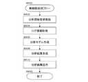
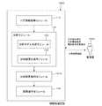
図1は、第1−A実施の形態の構成例についての概念的なモジュール構成図を示している。
なお、モジュールとは、一般的に論理的に分離可能なソフトウェア(コンピュータ・プログラム)、ハードウェア等の部品を指す。したがって、本実施の形態におけるモジュールはコンピュータ・プログラムにおけるモジュールのことだけでなく、ハードウェア構成におけるモジュールも指す。それゆえ、本実施の形態は、それらのモジュールとして機能させるためのコンピュータ・プログラム(コンピュータにそれぞれの手順を実行させるためのプログラム、コンピュータをそれぞれの手段として機能させるためのプログラム、コンピュータにそれぞれの機能を実現させるためのプログラム)、システム及び方法の説明をも兼ねている。ただし、説明の都合上、「記憶する」、「記憶させる」、これらと同等の文言を用いるが、これらの文言は、実施の形態がコンピュータ・プログラムの場合は、記憶装置に記憶させる、又は記憶装置に記憶させるように制御するの意である。また、モジュールは機能に一対一に対応していてもよいが、実装においては、1モジュールを1プログラムで構成してもよいし、複数モジュールを1プログラムで構成してもよく、逆に1モジュールを複数プログラムで構成してもよい。また、複数モジュールは1コンピュータによって実行されてもよいし、分散又は並列環境におけるコンピュータによって1モジュールが複数コンピュータで実行されてもよい。なお、1つのモジュールに他のモジュールが含まれていてもよい。また、以下、「接続」とは物理的な接続の他、論理的な接続(データの授受、指示、データ間の参照関係等)の場合にも用いる。「予め定められた」とは、対象としている処理の前に定まっていることをいい、本実施の形態による処理が始まる前はもちろんのこと、本実施の形態による処理が始まった後であっても、対象としている処理の前であれば、そのときの状況・状態に応じて、又はそれまでの状況・状態に応じて定まることの意を含めて用いる。
また、システム又は装置とは、複数のコンピュータ、ハードウェア、装置等がネットワーク(一対一対応の通信接続を含む)等の通信手段で接続されて構成されるほか、1つのコンピュータ、ハードウェア、装置等によって実現される場合も含まれる。「装置」と「システム」とは、互いに同義の用語として用いる。もちろんのことながら、「システム」には、人為的な取り決めである社会的な「仕組み」(社会システム)にすぎないものは含まない。
また、各モジュールによる処理毎に又はモジュール内で複数の処理を行う場合はその処理毎に、対象となる情報を記憶装置から読み込み、その処理を行った後に、処理結果を記憶装置に書き出すものである。したがって、処理前の記憶装置からの読み込み、処理後の記憶装置への書き出しについては、説明を省略する場合がある。なお、ここでの記憶装置としては、ハードディスク、RAM(Random Access Memory)、外部記憶媒体、通信回線を介した記憶装置、CPU(Central Processing Unit)内のレジスタ等を含んでいてもよい。FIG. 1 is a conceptual module configuration diagram of a configuration example of the first-A embodiment.
The module generally refers to components such as software (computer program) and hardware that can be logically separated. Therefore, the module in the present embodiment indicates not only a module in a computer program but also a module in a hardware configuration. Therefore, the present embodiment is a computer program for causing these modules to function (a program for causing a computer to execute each procedure, a program for causing a computer to function as each means, and a function for each computer. This also serves as an explanation of the program and system and method for realizing the above. However, for the sake of explanation, the words “store”, “store”, and equivalents thereof are used. However, when the embodiment is a computer program, these words are stored in a storage device or stored in memory. It is the control to be stored in the device. Modules may correspond to functions one-to-one, but in mounting, one module may be configured by one program, or a plurality of modules may be configured by one program, and conversely, one module May be composed of a plurality of programs. The plurality of modules may be executed by one computer, or one module may be executed by a plurality of computers in a distributed or parallel environment. Note that one module may include other modules. Hereinafter, “connection” is used not only for physical connection but also for logical connection (data exchange, instruction, reference relationship between data, etc.). “Predetermined” means that the process is determined before the target process, and not only before the process according to this embodiment starts but also after the process according to this embodiment starts. In addition, if it is before the target processing, it is used in accordance with the situation / state at that time or with the intention to be decided according to the situation / state up to that point.
In addition, the system or device is configured by connecting a plurality of computers, hardware, devices, and the like by communication means such as a network (including one-to-one correspondence communication connection), etc., and one computer, hardware, device. The case where it implement | achieves by etc. is also included. “Apparatus” and “system” are used as synonymous terms. Of course, the “system” does not include a social “mechanism” (social system) that is an artificial arrangement.
In addition, when performing a plurality of processes in each module or in each module, the target information is read from the storage device for each process, and the processing result is written to the storage device after performing the processing. is there. Therefore, description of reading from the storage device before processing and writing to the storage device after processing may be omitted. Here, the storage device may include a hard disk, a RAM (Random Access Memory), an external storage medium, a storage device via a communication line, a register in a CPU (Central Processing Unit), and the like.
第1−A実施の形態である情報処理装置100は、図1の例に示すように、ログ情報取得モジュール110、分析モジュール120、結果提示モジュール130を有している。 As illustrated in the example of FIG. 1, the
ログ情報取得モジュール110は、分析モジュール120と接続されている。ログ情報取得モジュール110は、事象の開始日時、その事象の終了日時、その事象が発生した場所を少なくとも含む事象の記録情報(以下、ログ情報ともいう)を記憶する事象記録情報記憶装置から対象とする事象の記録情報を取得する。例えば、ログ情報取得モジュール110は、人や物のある時刻における位置や状態のログ情報を取得する。そして、ログ情報とともに人や物の属性情報を取得するようにしてもよい。
分析の対象が、インフルエンザ等のウィルスの感染リスクであれば、事象としては、ある人のある部屋への入退室が該当する。この場合、事象の開始日時とは、その人がその部屋へ入室した日時(日時には、本実施の形態によって一意に特定できる時間であれば、日、時のいずれか一方、又はこれらの組み合わせだけでなく、年、月、分、秒、秒以下を含んでいてもよい。以下、同様。)に該当する。事象の終了日時とは、その人がその部屋から退室した日時が該当する。事象が発生した場所とは、その部屋が該当する。
なお、事象記録情報記憶装置は、ログ情報取得モジュール110からアクセス可能になっていれば、情報処理装置100内にあってもよいし、情報処理装置100外にあって通信回線によって接続されていてもよい。The log
If the object of analysis is an infection risk of a virus such as influenza, the event corresponds to entering or leaving a room of a certain person. In this case, the start date / time of the event is the date / time when the person entered the room (the date / time is a time that can be uniquely specified by the present embodiment, either day or time, or a combination thereof) May include year, month, minute, second, second or less, and so on. The end date and time of the event corresponds to the date and time when the person left the room. The place where the event occurred corresponds to the room.
The event record information storage device may be in the
分析モジュール120は、分析モデル生成モジュール122、分析結果生成モジュール124を有している。分析モジュール120は、ログ情報取得モジュール110、結果提示モジュール130と接続されている。分析モジュール120は、ログ情報を用いて分析を行う。
分析モデル生成モジュール122は、ログ情報取得モジュール110によって取得された事象の記録情報内の開始日時から予め定められた期間前又は期間後(以下では、主に予め定められた期間前を例示する)である日時をモデルの開始日時とし、その事象の記録情報内の終了日時から予め定められた期間前又は期間後(以下では、主に予め定められた期間後を例示する)である日時をモデルの終了日時とし、その事象による影響を算出するための影響情報を少なくとも含むモデルを生成する。分析モデル生成モジュール122は、取得したログ情報に分析目的に応じた分析モデル情報を付加した分析モデルを生成する。The
The analysis
分析結果生成モジュール124は、分析モデル生成モジュール122によって生成された第1の事象のモデルの開始日時及び終了日時により定まる期間と分析モデル生成モジュール122によって生成された第2の事象のモデルの開始日時及び終了日時により定まる期間が重複する期間と、その第1の事象のモデルの影響情報又はその第2の事象のモデルの影響情報に基づいて、その第1の事象とその第2の事象間の影響を分析する。分析結果生成モジュール124は、分析モデル生成モジュール122が生成した分析モデルから分析目的に応じた分析結果を生成する。
ここで、第2の事象は、第1の事象が発生した場所と同じ場所で発生した事象である。
結果提示モジュール130は、分析モジュール120と接続されている。結果提示モジュール130は、分析結果生成モジュール124による分析結果を出力する。ここで、出力するとは、利用者に提示すること、より具体的には、ディスプレイ等の表示装置に分析結果を表示すること、スピーカー等の音声出力装置によって分析結果を音声出力することの他に、例えば、プリンタ等の印刷装置で分析結果を印刷すること、FAX等の画像送信装置で分析結果の画像を送信すること、記憶装置へ分析結果を書き込むこと、他の情報処理装置へ渡すこと等が含まれる。The analysis
Here, the second event is an event that occurs in the same place as the place where the first event occurs.
The
図2は、ログ情報の例を示す説明図である。これは、人又は物である対象A、対象Bについて、あることが発生した場合のログ情報を示している。例えば、対象者Aが応接室にいたという事象のログ情報A210は、事象の開始日時である入室した時刻(tsa)、その事象の終了日時である退室した時刻(tea)、そしてその事象が発生した場所である応接室を示す応接室情報を含む。そして、対象者Aが退室した後に、対象者Bが同じ応接室に入室し、退室した場合のログ情報B220も、事象の開始日時である入室した時刻(tsb)、その事象の終了日時である退室した時刻(teb)、そしてその事象が発生した場所である応接室を示す応接室情報を含む。この場合、対象者Aと対象者Bは応接室で会うことなく、一般的には、対象者Aが応接室にいたということは対象者Bに影響を及ぼすことはないと処理されてしまう。
ログ情報取得モジュール110は、このようなログ情報を取得する。FIG. 2 is an explanatory diagram illustrating an example of log information. This shows log information when something happens to the subject A and the subject B that are people or things. For example, the log information A210 of the event that the subject A was in the reception room includes the entry time (tsa) that is the start date and time of the event, the exit time (tea) that is the end date and time of the event, and the occurrence of the event The reception room information indicating the reception room that is the location of the visitor is included. Then, after the subject A leaves the room, the subject B enters the same reception room, and the log information B220 when the subject leaves the room is also the entry time (tsb) that is the start date and time of the event, and the end date and time of the event. The time of leaving (teb) and the reception room information indicating the reception room where the event occurred are included. In this case, the subject person A and the subject person B do not meet in the drawing room, and generally, the fact that the subject person A is in the drawing room does not affect the subject person B.
The log
図3は、ログ情報に分析モデル情報を付加した分析モデルの例を示す説明図である。これは、ログ情報Aとログ情報Bにそれぞれ分析項目に応じた分析モデル情報を付加したことを示すものである。分析項目としては、例えば、インフルエンザ等のウィルスの感染リスクがある。
分析モデル情報A310は、ログ情報A210に加えて、時刻tsaから予め定められた期間前である時刻tsa’、時刻teaから予め定められた期間後である時刻tea’、事象による影響を算出するための影響情報である分析モデル付属情報を含む。
分析モデル情報B320は、ログ情報B220に加えて、時刻tsbから予め定められた期間前である時刻tsb’、時刻tebから予め定められた期間後である時刻teb’、事象による影響を算出するための影響情報である分析モデル付属情報を含む。
なお、分析モデル付属情報は、時間に応じて解析結果が変化するものである。例えば、分析モデル付属情報として、ウィルスの濃度変化を示す関数等が該当する。より具体的には、場所や感染症種類で決まる減衰関数である。図3の例で示すと、時刻tsaから時刻tsa’までとは、対象者Aがあるウィルスに感染している場合、対象者Aと直接会うことがなくても、対象者Aから対象者Bに感染する可能性があることを示している。
分析モデル生成モジュール122は、このような分析モデル情報A310、分析モデル情報B320を生成する。FIG. 3 is an explanatory diagram illustrating an example of an analysis model in which analysis model information is added to log information. This indicates that analysis model information corresponding to each analysis item is added to log information A and log information B, respectively. As an analysis item, for example, there is an infection risk of viruses such as influenza.
The analysis model information A310, in addition to the log information A210, calculates time tsa ′, which is before a predetermined period from time tsa, time tea ′, which is after a predetermined period from time tea, and the influence of an event. The analysis model attached information that is the influence information of
The analysis model information B320 calculates, in addition to the log information B220, the time tsb ′ that is before the predetermined period from the time tsb, the time teb ′ that is after the predetermined period from the time teb, and the influence of the event. The analysis model attached information that is the influence information of
Note that the analysis result attached to the analysis model changes the analysis result according to time. For example, a function indicating a change in virus concentration corresponds to the analysis model attached information. More specifically, it is a decay function determined by location and type of infectious disease. In the example of FIG. 3, from the time tsa to the time tsa ′, when the subject A is infected with a certain virus, the subject A to the subject B without having to meet the subject A directly. Indicates that there is a possibility of infection.
The analysis
図4は、分析モデルの重複期間の例を示す説明図である。これは、分析モデル情報A310と分析モデル情報B320が重複している期間である分析モデル重複期間410があることを示している。これは、いわゆるヒヤリ・ハット(感染等の事故には至らなかったが、事故が発生してもおかしくない一歩手前)の状態を示していることになる。これによって、対象者Aが応接室にいたという事象と対象者Bが同じ応接室にいたという事象間の影響を分析結果生成モジュール124が分析する。 FIG. 4 is an explanatory diagram illustrating an example of the overlap period of the analysis model. This indicates that there is an analysis
より詳細に説明する。
分析モデル生成モジュール122は、ログ情報集合Xの各要素を示す(1)式
The analysis
次に、分析結果生成モジュール124は、分析モデル生成モジュール122が生成した分析モデルの集合Uについて、Uの各要素uiに対して分析結果である(4)式を算出する。
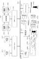
図5は、第1−Aの実施の形態を具現化した場合のシステム構成例を示す説明図である。
なお、このシステム構成例は、第1−Aの実施の形態(情報処理装置100)のみならず、第1−Bの実施の形態(情報処理装置1600)、第1−Cの実施の形態(情報処理装置2000)を具現化した場合にあてはまる。
ログDBサーバホスト505、スケジュール情報管理サーバホスト515、位置情報サーバホスト525、分析サーバホスト535、分析クライアントホスト560は、それぞれ通信回線599を介して接続されている。ログDBサーバホスト505と屋内行動ログDB510は、接続されている。スケジュール情報管理サーバホスト515とスケジュールDB520は、接続されている。分析サーバホスト535は、情報処理装置100と接続されている。情報処理装置100は、分析サーバホスト535、エリア特性DB540、個人属性情報DB545、感染リスクDB550、感染状態DB555と接続されている。位置情報サーバホスト525は、位置センサ530A〜530Hと接続されている。FIG. 5 is an explanatory diagram showing an example of a system configuration when the first-A embodiment is embodied.
This system configuration example is not limited to the 1-A embodiment (information processing apparatus 100), but also the 1-B embodiment (information processing apparatus 1600) and 1-C embodiment ( This is the case when the information processing apparatus 2000) is embodied.
The log
利用者580Aは、タグ585(例えば、アクティブRFID(Radio Frequency IDentification))を所持している。タグ585は、位置センサ530A〜530Hによって検出される。各位置センサは、タグ585に記憶されている利用者を示す利用者情報(例えば、社員ID(IDentification))を読み取り、検出した日時、その位置センサ自身の位置とともに位置情報サーバホスト525に記憶される。例えば、位置センサが各部屋に取り付けられている場合は、誰が、いつ、どの部屋に居たのであるかを示す行動ログデータとして、位置情報サーバホスト525に収集されることになる。そして、収集された行動ログデータをログDBサーバホスト505に渡し、図8に例示の行動ログデータテーブル800を屋内行動ログDB510に記憶する。 The
また、利用者580Aは、スケジュール情報管理サーバホスト515を用いて、スケジュールの設定等を行う。このスケジュールの設定等の情報をスケジュールDB520に記憶する。スケジュールの設定等の情報は、スケジュール情報管理サーバホスト515が各人のPC等の情報処理装置内のスケジューラープログラムから取得するようにしてもよい。
分析クライアントホスト560は、利用者580Aによる分析開始要求である操作指示を受け付け、分析サーバホスト535にその操作指示を渡し、情報処理装置100に例えばインフルエンザ等のウィルスの感染リスクの分析を行わせる。情報処理装置100は、個人属性情報DB545、エリア特性DB540、感染状態DB555、感染リスクDB550内のデータ又は屋内行動ログDB510、スケジュールDB520内のデータを用いて、分析を行い、分析サーバホスト535を介して分析クライアントホスト560に分析結果を提示して、利用者580Aに知らせる。また、分析クライアントホスト560は、利用者580Bによる分析条件を受け付け、分析サーバホスト535にその分析条件を渡し、情報処理装置100に例えばインフルエンザ等のウィルスの感染リスクの分析をその分析条件下で行わせる。情報処理装置100は、その分析条件に応じて、個人属性情報DB545、エリア特性DB540、感染状態DB555、感染リスクDB550内のデータ又は屋内行動ログDB510、スケジュールDB520内のデータを用いて、分析を行い、分析サーバホスト535を介して分析クライアントホスト560に分析結果を提示して、利用者580Bに知らせる。Further, the
The
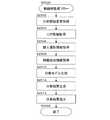
図6は、第1−Aの実施の形態による処理例を示すフローチャートである。
ステップS602では、情報処理装置100は、利用者によるマウス、キーボード、タッチパネル等の操作によって、分析開始要求である操作指示を取得する。例えば、図7に例示するような感染症リスクチェック画面700を利用者が操作し得る情報処理装置に提示する。感染症リスクチェック画面700は、分析開始ボタン710、リセットボタン720を有している。分析開始ボタン710が選択されることによって、本処理を開始する。また、利用者を示す利用者情報(図7の例では、社員ID(IDentification))も取得する。なお、利用者情報を取得するには、この情報処理装置にログインするときの利用者情報を利用すればよい。また、その利用者の健康状態を取得するようにしてもよい。
なお、利用者は文脈に応じて、社員、者、人、管理者等という。FIG. 6 is a flowchart illustrating a processing example according to the 1-A embodiment.
In step S602, the
The user is referred to as an employee, person, person, administrator, etc. depending on the context.
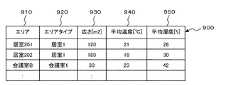
ステップS604では、ログ情報取得モジュール110が、屋内行動ログDB510からログ情報を取得する。屋内行動ログDB510は、各人の過去の行動の記録であるログデータ、特に屋内行動の実績を捕捉したログデータを記憶する。例えば、図8に例示する行動ログデータテーブル800を記憶する。図8は、行動ログデータテーブル800のデータ構造例を示す説明図である。行動ログデータテーブル800は、開始時刻欄810、終了時刻欄820、社員ID欄830、検出エリア欄840、感染状態欄850を有している。開始時刻欄810は、社員ID欄830の利用者が検出エリア欄840の部屋に入室した日時を記憶する。終了時刻欄820は、社員ID欄830の利用者が検出エリア欄840の部屋から退室した日時を記憶する。社員ID欄830は、対象となっている利用者を示す利用者情報を記憶する。例えば、社員IDである。検出エリア欄840は、その利用者(正確には、その利用者が所持しているタグ585)を検出したエリア(場所)を示すエリア情報を記憶する。例えば、会議室名である。感染状態欄850は、開始時刻欄810から終了時刻欄820の間における社員ID欄830の利用者の感染状態を記憶する。なお、感染状態は個人属性情報として、個人属性情報DB545に記憶されており、そこから取得する。感染状態は、自己申告、健康診断の結果、サーモセンサによる検出結果であるログデータ、咳センサのログデータなどに基づいている。また、感染状態として、ウィルス名、症状の状態、それらの複合(例えば結核初期、インフルエンザ末期等)であってもよい。また、行動ログデータテーブル800には、ログ情報として、過去感染履歴、マスク着用有無、咳検出結果等を含めてもよい。 In step S604, the log
また、行動ログデータテーブル800の検出エリア欄840にあるエリアから、そのエリアの属性である特性をエリア特性DB540から取り出すようにしてもよい。エリア特性DB540は、例えばエリアデータテーブル900を記憶している。図9は、エリアデータテーブル900のデータ構造例を示す説明図である。エリアデータテーブル900は、エリア欄910、エリアタイプ欄920、広さ欄930、平均温度欄940、平均湿度欄950を有している。エリア欄910は、エリアを示すエリア情報を記憶する。例えば、会議室名である。エリアタイプ欄920は、そのエリアのタイプ(種類)を記憶する。例えば、居室、会議室等である。広さ欄930は、そのエリアの面積を記憶する。平均温度欄940は、そのエリアにおける平均温度を記憶する。平均湿度欄950は、そのエリアにおける湿度を記憶する。平均温度欄940、平均湿度欄950は、実際に計測した温度/湿度データを用いてもよい。また、エリアデータテーブル900には、そのエリアの特性として、最終換気時刻等を含めてもよい。
対象としている検出エリア欄840のエリアに該当するエリアデータテーブル900のエリア欄910を検索し、そのエリアの特性(エリアタイプ欄920、広さ欄930、平均温度欄940、平均湿度欄950)を取得してもよい。Further, from the area in the
The
また、行動ログデータテーブル800の感染状態欄850にある感染状態から、その感染状態の属性を感染状態DB555から取り出すようにしてもよい。感染状態DB555は、例えば感染状態データテーブル1000を記憶している。図10は、感染状態データテーブル1000のデータ構造例を示す説明図である。感染状態データテーブル1000は、感染状態欄1010、毒性欄1020、感染力欄1030、感染経路欄1040を有している。感染状態欄1010は、感染状態を記憶する。毒性欄1020は、その感染状態における毒性を記憶する。感染力欄1030は、その感染状態における感染力を記憶する。感染経路欄1040は、その感染状態における感染経路を記憶する。毒性欄1020、感染力欄1030は感染値の最大値に影響する。感染経路欄1040は空気感染、飛沫感染、接触感染があり、感染値の持続時間に関係する。
対象としている感染状態欄850の感染状態に該当する感染状態データテーブル1000の感染状態欄1010を検索し、その感染状態の属性(毒性欄1020、感染力欄1030、感染経路欄1040)を取得してもよい。Further, from the infection state in the
The
ステップS606では、分析モデル生成モジュール122が、分析モデルを生成する。ステップS604で取得したログ情報(行動ログデータテーブル800)、エリアデータ(エリアデータテーブル900)、感染状態データ(感染状態データテーブル1000)に基づいて、分析モデルを生成する。生成する分析モデルとして、例えば、分析モデルデータテーブル1100がある。図11は、分析モデルデータテーブル1100のデータ構造例を示す説明図である。分析モデルデータテーブル1100は、開始時刻欄1110、終了時刻欄1120、社員ID欄1130、検出エリア欄1140、感染状態欄1150、分析モデル開始時刻欄1160、分析モデル終了時刻欄1170、感染リスク関数欄1180を有している。開始時刻欄1110から感染状態欄1150は、行動ログデータテーブル800の開始時刻欄810から感染状態欄850に該当し、それぞれ取得した開始時刻、終了時刻、社員ID、検出エリア、感染状態を記憶する。分析モデル開始時刻欄1160から感染リスク関数欄1180が分析モデルとして付加するものである。分析モデル開始時刻欄1160は、開始時刻欄1110に記憶されている開始時刻から予め定められた期間前(この場合は、0秒)である日時を記憶する。分析モデル終了時刻欄1170は、終了時刻欄1120に記憶されている終了時刻から予め定められた期間後である日時を記憶する。感染リスク関数欄1180は、事象による影響を算出するための影響情報である感染リスク関数を記憶する。 In step S606, the analysis
分析モデル開始時刻欄1160から感染リスク関数欄1180内のデータの生成について説明する。前述の分析モデル生成関数Fから、検出エリア特性(エリアデータテーブル900の広さ、温度、湿度等)と感染状態(感染状態データテーブル1000の感染力、毒性、感染経路)の組み合わせに応じた感染リスク関数を適用する。
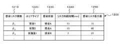
まず、分析モデル生成のために利用する感染リスク関数データテーブル1200について説明する。感染リスクDB550は、例えば感染リスク関数データテーブル1200を記憶している。図12は、感染リスク関数データテーブル1200のデータ構造例を示す説明図である。感染リスク関数データテーブル1200は、感染リスク関数欄1210、エリアタイプ欄1220、感染状態欄1230、リスク持続時間欄1240、感染リスク最大値欄1250を有している。感染リスク関数欄1210は、感染リスク値を求める感染リスク関数を記憶する。エリアタイプ欄1220は、その感染リスク関数を適用するエリアタイプを記憶する。感染状態欄1230は、その感染リスク関数を適用する感染状態を記憶する。つまり、感染リスク関数欄1210、エリアタイプ欄1220の条件に合致した場合に、その感染リスク関数を適用する。リスク持続時間欄1240は、その感染のリスクが持続する時間を記憶する。なお、リスク持続時間欄1240の値は、空気感染の飛沫核の落下速度、飛沫感染の飛沫粒子落下速度等に基づいて設定する。感染リスク最大値欄1250は、その感染のリスクにおける最大値を記憶する。Generation of data in the infection
First, the infection risk function data table 1200 used for generating an analysis model will be described. The
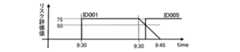
ステップS608では、分析結果生成モジュール124が、ステップS602で取得した利用者情報が示す利用者に関する分析結果を生成する。例えば、開始時刻欄1110、終了時刻欄1120、社員ID欄1130、検出エリア欄1140から、社員ID:001の社員は、居室201に9:00:00から9:30:00までいたことが判明し、社員ID:005の社員は、居室201に9:35:00から10:00:00までいたことが判明する。そして、感染状態欄1150から、社員ID:001の社員は、感染Aの感染状態であることが判明する。また、居室201は、エリアデータテーブル900のエリアタイプ欄920からエリアタイプ:居室1である。そして、エリアタイプ:居室1、感染状態:感染Aに適している感染リスク関数は、感染リスク関数データテーブル1200に基づいて、β1である。こうして、感染リスク関数欄1180に記憶させる感染リスク関数を取得する。そして、感染リスク関数:β1は、リスク持続時間欄1240から、リスク持続時間が15分である。したがって、分析モデル終了時刻欄1170に記憶させる分析モデル終了時刻は、終了時刻欄1120に15分を加えた時刻(09:45:00)である。そして、感染リスク最大値欄1250から、感染リスク最大値は75であるので、社員ID:001と社員ID:005の間の居室201における感染リスク値は、図13の例に示すようなグラフになっている。社員ID:001が入室した09:30:00からリスク評価値である感染リスク値は75となり、退室した09:30:00から下がり始め、リスク持続時間である15分まで下がる。そして、社員ID:005が入室した09:35:00には、リスク評価値は50となっていることを示している。In step S608, the analysis
社員ID:001(感染者)と社員ID:005(健康)の分析モデルが時間軸上で重なった期間の中で最も感染リスクの高い値を感染リスク値(図13の例では50)とする。なお、感染リスク値の計算は、分析モデルが時間軸上で重なった期間を積分範囲として求めてもよいし、関数を離散的に定義する場合は各時刻の感染リスク値の和でもよい。
そして、その感染リスク値からの分析として、感染リスクの判定結果、推奨行動等を感染リスクDB550内の感染リスク判定テーブル1400から取得する。図14は、感染リスク判定テーブル1400のデータ構造例を示す説明図である。感染リスク判定テーブル1400は、感染リスク値欄1410、感染リスク判定結果欄1420、推奨行動欄1430を有している。感染リスク値欄1410は、感染リスク値の範囲を記憶する。感染リスク判定結果欄1420は、その感染リスク値の範囲にある場合の感染の可能性を示す感染リスク判定結果情報を記憶する。推奨行動欄1430は、その感染リスク値の範囲にある場合の推奨行動情報を記憶する。分析結果生成モジュール124は、感染リスク値が該当する感染リスク値の範囲の行を取得し、その行の感染リスク判定結果欄1420、推奨行動欄1430内の情報を取得する。The infection risk value (50 in the example of FIG. 13) is the highest infection risk value in the period when the analysis models of employee ID: 001 (infected person) and employee ID: 005 (health) overlap on the time axis. . The calculation of the infection risk value may be obtained as an integration range during which the analysis models overlap on the time axis, or when the function is defined discretely, the sum of the infection risk values at each time may be used.
Then, as an analysis from the infection risk value, an infection risk determination result, recommended behavior, and the like are acquired from the infection risk determination table 1400 in the
ステップS610では、結果提示モジュール130が、ステップS608での分析結果を提示する。例えば、図15に例示する感染症リスク評価結果画面1500のように、利用者が操作し得る情報処理装置の表示装置に提示する。 In step S610, the
なお、ステップS602で取得した利用者情報が示す利用者に関する分析結果を生成するために、前述の処理例では、ログ情報取得モジュール110が全ての行動ログデータを取り出し、分析モデル生成モジュール122が全ての分析モデルを生成して、分析結果生成モジュール124が、対象となっている利用者Aの分析モデルの開始時刻から終了時刻までの期間と、その利用者Aと同じエリアにいたことがあり、分析モデルの開始時刻から終了時刻までの期間が重なる利用者Bを取得している。
しかし、ログ情報取得モジュール110が、ステップS602で取得した利用者情報に該当する社員IDを社員ID欄830から検索し、そのログ情報(開始時刻欄810、終了時刻欄820、社員ID欄830、検出エリア欄840、感染状態欄850)を取得し、その利用者Aがいた部屋を検出エリア欄840から取り出し、同じ部屋にいたことがある利用者Bのログ情報を取り出すようにしてもよい。つまり、ログ情報取得モジュール110は、ステップS602で取得した利用者情報が示す利用者Aとその利用者Aに関係しそうな利用者Bの行動ログデータだけを取得するようにしてもよい。そして、分析モデル生成モジュール122がそれらの分析モデルを生成して、分析結果生成モジュール124が、対象となっている利用者Aの分析モデルの開始時刻から終了時刻までの期間と、分析モデルの開始時刻から終了時刻までの期間が重なる利用者Bを取得するようにしてもよい。In addition, in order to generate the analysis result regarding the user indicated by the user information acquired in step S602, in the above processing example, the log
However, the log
図16は、第1−Bの実施の形態の構成例についての概念的なモジュール構成図である。情報処理装置1600は、ログ情報取得モジュール110、分析モジュール120、分析結果集約モジュール1610、結果提示モジュール130を有している。なお、第1−Aの実施の形態と同種の部位には同一符号を付し重複した説明を省略する(以下、同様)。
前述の第1−Aの実施の形態の利用者は、一般の利用者であり、その利用者本人の感染リスクの分析結果を提示するものであった。第1−Bの実施の形態の利用者は管理者であり、特定の者の感染リスクの分析結果を提示するものではなく、例えば、ある組織に属している者達の感染リスクの分析結果を提示するものである。FIG. 16 is a conceptual module configuration diagram of a configuration example according to the first 1-B embodiment. The
The user of the first-A embodiment described above is a general user and presents the analysis result of the infection risk of the user himself / herself. The user of the first-B embodiment is an administrator and does not present the analysis result of infection risk of a specific person. For example, the analysis result of infection risk of persons belonging to a certain organization is displayed. It is to be presented.
そのために、情報処理装置1600は、管理者1699によるマウス、キーボード、タッチパネル等の操作によって、操作指示である分析条件、分析開始要求又は集約条件変更を取得する。
分析結果集約モジュール1610は、分析モジュール120、結果提示モジュール130と接続されており、その管理者1699の操作指示に基づいて、分析結果生成モジュール124による分析結果を集計する。例えば、分析条件に合致する者に対して、感染リスクの判定結果である感染可能性の程度毎に人数を集計してもよい。
結果提示モジュール130は、分析結果集約モジュール1610と接続されており、分析結果集約モジュール1610による集計結果を管理者1699に提示する。Therefore, the
The analysis
The
図17は、第1−Bの実施の形態による処理例を示すフローチャートである。なお、図6に示した第1−Aの実施の形態による処理例のフローチャートと同じ処理の場合は、図6の例に示したステップを示して、説明を省略する。
ステップS1702では、情報処理装置1600が、分析開始要求を取得する。ステップS602と同等の処理である。
ステップS1704では、情報処理装置1600が、分析条件設定を取得する。管理者1699によるマウス、キーボード、タッチパネル等の操作によって、分析条件設定を取得する。分析条件として、期間、対象としている人が属している組織、場所のいずれか1つ又はこれらの組み合わせであってもよい。図18は、分析条件設定画面1800の例を示す説明図である。分析条件設定画面1800は、分析期間設定欄1810、分析組織設定欄1820、分析エリア設定欄1830、分析開始ボタン1840、リセットボタン1850を有している。分析期間設定欄1810は、分析対象となる期間を設定するための欄である。分析組織設定欄1820は、分析対象となる組織を設定するための欄である。分析エリア設定欄1830は、分析対象となるエリアを設定するための欄である。分析開始ボタン1840が選択されたときの分析期間設定欄1810、分析組織設定欄1820、分析エリア設定欄1830の設定に基づいて、分析条件設定を取得する。なお、期間、エリア、組織の他に、感染症名、年齢、職階等も分析条件として設定するようにしてもよい。FIG. 17 is a flowchart illustrating a processing example according to the 1-B embodiment. In the case of the same processing as the flowchart of the processing example according to the 1-A embodiment shown in FIG. 6, the steps shown in the example of FIG.
In step S1702, the
In step S1704, the
ステップS1706では、ログ情報取得モジュール110が、ログ情報を取得する。ステップS604と同等の処理である。
ステップS1708では、分析モデル生成モジュール122が、分析モデルを生成する。ステップS606と同等の処理である。
ステップS1710では、分析結果生成モジュール124が、分析結果を生成する。ステップS608と同等の処理である。
なお、ステップS1706からステップS1710の処理では、第1−Aの実施の形態による処理例と同等に、全ての行動ログデータに対して分析モデルを生成した処理をしてもよいし、ステップS1704で取得した分析条件に合致したものを対象とした処理を行うようにしてもよい。In step S1706, the log
In step S1708, the analysis
In step S1710, the analysis
Note that in the processing from step S1706 to step S1710, an analysis model may be generated for all action log data, as in the processing example according to the first-A embodiment, or in step S1704. You may make it perform the process for what matched the acquired analysis conditions.
ステップS1712では、分析結果集約モジュール1610が、分析結果を集約する。ステップS1704で取得した分析条件に基づいて、分析結果を集計している。
ステップS1714では、結果提示モジュール130が、分析結果を提示する。例えば、図19に例示する感染症リスク分析画面1900のように、管理者1699が操作し得る情報処理装置の表示装置に提示する。図19は、感染症リスク分析画面1900の例を示す説明図である。感染症リスク分析画面1900は、感染リスク分析条件を提示する分析期間表示領域1910、分析エリア表示領域1920、分析組織表示領域1930と、感染リスク評価結果を提示する感染表示領域1940、感染疑い表示領域1950、感染疑いリスト1960と、再集約ボタン1980、閉じるボタン1990を有している。分析期間表示領域1910、分析エリア表示領域1920、分析組織表示領域1930は、ステップS1704で取得した分析条件(図18に例示した分析期間設定欄1810、分析組織設定欄1820、分析エリア設定欄1830に該当)を提示する欄である。感染表示領域1940、感染疑い表示領域1950は、具体的には、感染リスク判定テーブル1400の感染リスク判定結果欄1420の感染可能性の程度毎に、その程度に合致する人数を集計したものである。感染疑いリスト1960は、感染疑い表示領域1950に分類された者の詳細を提示するものであり、社員ID欄1962、感染日欄1964、感染エリア欄1966、感染タイプ欄1968、現在状態欄1970、感染リスク値欄1972を有している。また、各欄毎に、ソートによる並べ替え、条件に合致するものを取り出すフィルタリング等の処理を行えるようにしてもよい。In step S1712, the analysis
In step S1714, the
ステップS1716では、分析結果集約モジュール1610が、集約条件が変更されたか否かを判断し、変更された場合はステップS1712からの処理を行い、それ以外の場合は処理を終了する(ステップS1799)。例えば、図19に例示の分析期間表示領域1910、分析エリア表示領域1920、分析組織表示領域1930には変更ボタンがあるが、この変更ボタンが選択された場合は、これらの分析条件を変更できるような表示を行う。そして、分析条件が変更された後に再集約ボタン1980が選択された場合が、集約条件が変更された場合に該当する。 In step S1716, the analysis
図20は、第1−Cの実施の形態の構成例についての概念的なモジュール構成図である。情報処理装置2000は、ログ情報取得モジュール110、分析モジュール120、ログ情報修正モジュール2010、スケジュール情報記憶モジュール2020、分析結果集約モジュール1610、結果提示モジュール130を有している。
第1−Cの実施の形態は、過去の行動ログデータを変更してシミュレーションをすること、又は将来の予定であるスケジュール情報を用いてシミュレーションをすることを行う。FIG. 20 is a conceptual module configuration diagram of a configuration example of the first-C embodiment. The
In the first-C embodiment, simulation is performed by changing past action log data, or simulation is performed using schedule information that is a future plan.
ログ情報修正モジュール2010は、分析モジュール120、スケジュール情報記憶モジュール2020と接続されている。ログ情報修正モジュール2010は、屋内行動ログDB510に記憶されている事象の開始日時、その事象の終了日時、その事象が発生した場所を少なくとも含む事象の行動ログデータの内、いずれか1つ又はこれらの組み合わせを修正する。また、利用者の将来の予定である事象の開始日時、その事象の終了日時、その事象が発生する場所を少なくとも含む事象の予定情報を記憶するスケジュール情報記憶モジュール2020から対象とする利用者の予定情報を付加する修正を行うようにしてもよい。なお、修正には、既に記憶されている行動ログデータを変更、削除することの他、新たに予定情報を行動ログデータとして付加することを含む。
スケジュール情報記憶モジュール2020は、ログ情報修正モジュール2010と接続されている。スケジュール情報記憶モジュール2020は、スケジュール情報である利用者の将来の予定である事象の開始日時、その事象の終了日時、その事象が発生する場所を少なくとも含む情報を記憶する。スケジュール情報記憶モジュール2020内の情報は、スケジュールDB520から取得する。The log
The schedule
図21は、第1−Cの実施の形態による処理例を示すフローチャートである。なお、図17に示した第1−Bの実施の形態による処理例のフローチャートと同じ処理の場合は、図17の例に示したステップを示して、説明を省略する。
ステップS2102では、情報処理装置2000が、分析開始要求を取得する。ステップS1702と同等の処理である。
ステップS2104では、情報処理装置2000が、分析条件設定を取得する。ステップS1704と同等の処理である。FIG. 21 is a flowchart illustrating a processing example according to the 1-C embodiment. In the case of the same process as the flowchart of the process example according to the 1-B embodiment shown in FIG. 17, the steps shown in the example of FIG.
In step S2102, the
In step S2104, the
ステップS2106では、ログ情報取得モジュール110が、ログ情報を取得する。ステップS1706と同等の処理である。
ステップS2108では、ログ情報修正モジュール2010が、ログ情報を修正する。管理者2099によるマウス、キーボード、タッチパネル等の操作によって、シミュレーション条件を受け付け、行動ログデータを修正する。シミュレーション条件の設定用の画面として、例えば、感染症リスクシミュレーション画面2200がある。図22は、感染症リスクシミュレーション画面2200の例を示す説明図である。感染症リスクシミュレーション画面2200は、分析条件設定タブ2210、ログ情報修正(シミュレーション)タブ2220を有している。ログ情報修正(シミュレーション)タブ2220は、対象とする者の過去の行動ログデータを提示する対象者(ID001)ログ表示領域2222、対象者(ID005)ログ表示領域2224があり、それらの行動ログデータを修正するための修正ボタン2226、修正ボタン2228があり、新たにスケジュール情報から行動ログデータを追加するためのログ追加ボタン2290を有している。図22の例では、部屋への入室日時、退室日時を変更し得るようになっているが、この他にその部屋、感染状態等を変更し得るようにしてもよい。また、ログ追加ボタン2290が選択された場合は、ログ情報修正モジュール2010は、スケジュール情報記憶モジュール2020から対象とする利用者のスケジュール情報を取り出して、行動ログデータとして追加する。In step S2106, the log
In step S2108, the log
ステップS2110では、分析モデル生成モジュール122が、分析モデルを生成する。ステップS1708と同等の処理である。
ステップS2112では、分析結果生成モジュール124が、分析結果を生成する。ステップS1710と同等の処理である。
ステップS2114では、分析結果集約モジュール1610が、分析結果を集約する。ステップS1712と同等の処理である。
ステップS2116では、結果提示モジュール130が、分析結果を提示する。ステップS1714と同等の処理である。
ステップS2118では、分析結果集約モジュール1610が、集約条件が変更されたか否かを判断し、変更された場合はステップS2114からの処理を行い、それ以外の場合はステップS2120へ進む。ステップS1716と同等の処理である。
ステップS2120では、ログ情報修正モジュール2010が、分析条件が変更されたか否かを判断し、変更された場合はステップS2104からの処理を行い、それ以外の場合は処理を終了する(ステップS2199)。In step S2110, the analysis
In step S2112, the analysis
In step S2114, the analysis
In step S2116, the
In step S2118, the analysis
In step S2120, the log
なお、第1−Cの実施の形態では、図20に例示するように分析結果集約モジュール1610を用いたが、分析結果集約モジュール1610がなく、分析モジュール120と結果提示モジュール130が接続されていてもよい。そして、第1−Aの実施の形態にように、管理者2099ではなく、一般の利用者によって使用されてもよい。
また、第1の実施の形態(第1−Aの実施の形態、第1−Bの実施の形態、第1−Cの実施の形態を含む)では、感染のリスクを分析したが、ある人物に会う機会の評価値(いわゆる機会損失)を分析するようにしてもよい。例えば、「あと2分早くその会議室に着いていたらN部長に会うことができた」等の分析結果を得るようにしてもよい。In the first-C embodiment, the analysis
In the first embodiment (including the 1-A embodiment, the 1-B embodiment, and the 1-C embodiment), the risk of infection was analyzed. You may make it analyze the evaluation value (what is called opportunity loss) of the opportunity to meet. For example, an analysis result such as “If I arrived in the conference room two minutes earlier, I could meet the N manager” may be obtained.
図23は、第2の実施の形態を具現化した場合のシステム構成例を示す説明図である。第2の実施の形態は、分析の対象が画像出力装置の出力結果を盗み見ることによる情報漏洩のリスクを分析するものである。
ログDBサーバホスト2310、分析サーバホスト2320、位置情報サーバホスト2330、機器稼働情報サーバホスト2340、分析クライアントホスト2350は、それぞれ通信回線2399を介して接続されている。ログDBサーバホスト2310は、屋内行動ログDB2312、機器稼働ログDB2314と接続されている。分析サーバホスト2320は、情報処理装置2400と接続されている。情報処理装置2400は、図24を用いて後述する。なお、情報処理装置2400の代わりに図36に例示する情報処理装置3600、図40に例示する情報処理装置4000でもよい。情報処理装置2400は、分析サーバホスト2320、個人属性情報DB2322、エリア特性DB2324、情報媒体情報DB2326、プリンタ情報DB2328と接続されている。位置情報サーバホスト2330は、位置センサ2335A〜2335Hと接続されている。機器稼働情報サーバホスト2340は、PC2342A、2342B、複合機2344A、2344B、2344Cと接続されている。なお、複合機とは、スキャナ、プリンタ、複写機、ファックス等のいずれか2つ以上の機能を有している画像処理装置であるが、ここでは、画像出力装置の一例である。FIG. 23 is an explanatory diagram illustrating an example of a system configuration when the second embodiment is implemented. In the second embodiment, the risk of information leakage due to an object of analysis stealing the output result of the image output apparatus is analyzed.
The log
利用者2380Aは、タグ2385(例えば、アクティブRFID(Radio Frequency IDentification))を所持している。タグ2385は、位置センサ2335A〜2335Hによって検出される。各位置センサは、タグ2385に記憶されている利用者を示す利用者情報(例えば、社員ID(IDentification))を読み取り、検出した日時、その位置センサ自身の位置とともに位置情報サーバホスト2330に記憶される。例えば、位置センサが各部屋に取り付けられている場合は、誰が、いつ、どの部屋に居たのであるかを示す行動ログデータとして、位置情報サーバホスト2330に収集されることになる。そして、収集された行動ログデータをログDBサーバホスト2310に渡し、屋内行動ログDB2312に記憶する。
機器稼働情報サーバホスト2340は、PC2342A、複合機2344A等の稼働状況(例えば、PC2342Aから複合機2344Aに出力指示が送信されたこと、複合機2344Aが印刷したこと、その印刷物が回収されたこと等)を検知し、検知した情報を機器稼働ログデータとして、ログDBサーバホスト2310に渡し、機器稼働ログDB2314に記憶する。 The device operation
分析クライアントホスト2350は、利用者2380Aによる分析開始要求である操作指示を受け付け、分析サーバホスト2320にその操作指示を渡し、情報処理装置2400に例えば画像出力装置の出力結果を盗み見ることによる情報漏洩のリスクの分析を行わせる。情報処理装置2400は、個人属性情報DB2322、エリア特性DB2324、情報媒体情報DB2326、プリンタ情報DB2328内のデータ又は屋内行動ログDB2312、機器稼働ログDB2314内のデータを用いて、分析を行い、分析サーバホスト2320を介して分析クライアントホスト2350に分析結果を提示して、利用者2380Aに知らせる。また、分析クライアントホスト2350は、管理者2380Bによる分析条件を受け付け、分析サーバホスト2320にその分析条件を渡し、情報処理装置2400に例えば画像出力装置の出力結果を盗み見ることによる情報漏洩のリスクの分析をその分析条件下で行わせる。情報処理装置2400は、その分析条件に応じて、個人属性情報DB2322、エリア特性DB2324、情報媒体情報DB2326、プリンタ情報DB2328内のデータ又は屋内行動ログDB2312、機器稼働ログDB2314内のデータを用いて、分析を行い、分析サーバホスト2320を介して分析クライアントホスト2350に分析結果を提示して、管理者2380Bに知らせる。 The
図24は、第2−Aの実施の形態の構成例についての概念的なモジュール構成図である。情報処理装置2400は、ログ情報取得モジュール110、分析モジュール120、個人属性情報取得モジュール2410、情報媒体情報取得モジュール2420、結果提示モジュール130を有している。 FIG. 24 is a conceptual module configuration diagram of a configuration example according to the 2-A embodiment. The
ログ情報取得モジュール110は、分析モジュール120と接続されている。ログ情報取得モジュール110は、事象の開始日時、その事象の終了日時、その事象が発生した場所を少なくとも含む事象の記録情報(以下、ログ情報ともいう)を記憶する事象記録情報記憶装置から対象とする事象の記録情報を取得する。例えば、ログ情報取得モジュール110は、人や物のある時刻における位置や状態のログ情報を、図23に例示した屋内行動ログDB2312、機器稼働ログDB2314から取得する。そして、ログ情報とともに人や物の属性情報を、図23に例示した個人属性情報DB2322、エリア特性DB2324、情報媒体情報DB2326、プリンタ情報DB2328から取得するようにしてもよい。
分析の対象が、画像出力装置(例えば、プリンタ、ディスプレイ等)の出力結果を盗み見ることによる情報漏洩のリスクであれば、第1の事象としては、ある人のある部屋への入退室が該当する。第2の事象としては、ある画像出力装置による出力が該当する。この場合、第1の事象の開始日時とは、その人がその部屋へ入室した日時に該当する。第1の事象の終了日時とは、その人がその部屋から退室した日時が該当する。第1の事象が発生した場所とは、その部屋が該当する。第2の事象の開始日時とは、その画像出力装置が出力した日時に該当する。第2の事象の終了日時とは、その画像出力装置が出力した印刷物が回収された日時が該当する。第2の事象が発生した場所とは、その画像出力装置が設置されている部屋が該当する。The log
If the object of analysis is the risk of information leakage due to the stealing of the output result of an image output device (for example, a printer, a display, etc.), the first event corresponds to entering or leaving a room of a certain person. . The second event corresponds to an output from a certain image output device. In this case, the start date and time of the first event corresponds to the date and time when the person entered the room. The end date and time of the first event corresponds to the date and time when the person leaves the room. The place where the first event occurs corresponds to the room. The start date and time of the second event corresponds to the date and time output by the image output apparatus. The end date and time of the second event corresponds to the date and time when the printed matter output by the image output apparatus is collected. The place where the second event occurs corresponds to the room where the image output apparatus is installed.
分析モジュール120は、分析モデル生成モジュール122、分析結果生成モジュール124を有している。分析モジュール120は、ログ情報取得モジュール110、個人属性情報取得モジュール2410、情報媒体情報取得モジュール2420、結果提示モジュール130と接続されている。分析モジュール120は、ログ情報を用いて分析を行う。
分析モデル生成モジュール122は、ログ情報取得モジュール110によって取得された事象の記録情報内の開始日時から予め定められた期間前である日時をモデルの開始日時とし、その事象の記録情報内の終了日時から予め定められた期間後である日時をモデルの終了日時とし、その事象による影響を算出するための影響情報を少なくとも含むモデルを生成する。分析モデル生成モジュール122は、取得したログ情報に分析目的に応じた分析モデル情報を付加した分析モデルを生成する。The
The analysis
分析結果生成モジュール124は、分析モデル生成モジュール122によって生成された第1の事象のモデルの開始日時及び終了日時により定まる期間と分析モデル生成モジュール122によって生成された第2の事象のモデルの開始日時及び終了日時により定まる期間が重複する期間と、その第1の事象のモデルの影響情報又はその第2の事象のモデルの影響情報に基づいて、その第1の事象とその第2の事象間の影響を分析する。分析結果生成モジュール124は、分析モデル生成モジュール122が生成した分析モデルから分析目的に応じた分析結果を生成する。
ここで、第2の事象は、第1の事象が発生した場所と同じ場所で発生した事象である。つまり、対象とする人が入室した部屋にある画像出力装置が出力を行った場合である。
結果提示モジュール130は、分析モジュール120と接続されている。結果提示モジュール130は、分析結果生成モジュール124による分析結果を提示する。The analysis
Here, the second event is an event that occurs in the same place as the place where the first event occurs. In other words, this is a case where the image output device in the room where the target person has entered performs the output.
The
個人属性情報取得モジュール2410は、分析モジュール120と接続されている。図23に例示した個人属性情報DB2322から個人属性情報を取得する。
情報媒体情報取得モジュール2420は、分析モジュール120と接続されている。図23に例示した情報媒体情報DB2326から情報媒体情報を取得する。
そして、分析モジュール120内の分析モデル生成モジュール122又は分析結果生成モジュール124は、個人属性情報取得モジュール2410によって取得された個人属性情報又は情報媒体情報取得モジュール2420によって取得された情報媒体情報を用いて、前述の処理を行うようにしてもよい。
なお、情報処理装置2400への分析開始の要求は、利用者2499による複合機2490のタッチパネル等への操作によって行われてもよい。また、結果提示モジュール130は複合機2490のタッチパネル等へ分析結果を提示し、利用者2499へ知らせるようにしてもよい。また、複合機2490は、放置プリント期間(出力した印刷媒体が回収されないでいる期間)が予め定められた期間を超えて発生した場合に、情報漏洩リスクの分析開始要求を情報処理装置2400に送信するようにしてもよい。The personal attribute
The information medium
The analysis
The analysis start request to the
図25は、第2−Aの実施の形態による処理例を示すフローチャートである。
ステップS2502では、情報処理装置2400は、利用者によるマウス、キーボード、タッチパネル等の操作によって、分析開始要求である操作指示を取得する。
ステップS2504では、ログ情報取得モジュール110が、屋内行動ログDB2312、機器稼働ログDB2314からログ情報を取得する。屋内行動ログDB2312は、各人の過去の行動の記録であるログデータ、特に屋内行動の実績を捕捉したログデータを記憶する。例えば、図26に例示する行動ログテーブル2600を記憶する。図26は、行動ログテーブル2600のデータ構造例を示す説明図である。行動ログテーブル2600は、開始時刻欄2610、終了時刻欄2620、社員ID欄2630、検出エリア欄2640を有している。開始時刻欄2610は、社員ID欄2630の利用者が検出エリア欄2640の部屋に入室した日時を記憶する。終了時刻欄2620は、社員ID欄2630の利用者が検出エリア欄2640の部屋から退室した日時を記憶する。社員ID欄2630は、対象となっている利用者を示す利用者情報を記憶する。例えば、社員IDである。検出エリア欄2640は、その利用者(正確には、その利用者が所持しているタグ2385)を検出したエリア(場所)を示すエリア情報を記憶する。例えば、会議室名である。FIG. 25 is a flowchart illustrating a processing example according to the 2-A embodiment.
In step S2502, the
In step S2504, the log
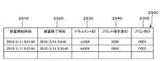
機器稼働ログDB2314は、各機器の過去の行動の記録であるログデータ、特に画像出力装置によって出力された印刷媒体が放置された開始時刻と終了時刻の実績であるログデータを記憶する。例えば、図29に例示するプリントログテーブル2900を記憶する。図29は、プリントログテーブル2900のデータ構造例を示す説明図である。プリントログテーブル2900は、放置開始時刻欄2910、放置終了時刻欄2920、ドキュメントID欄2930、プリント指示者ID欄2940、プリンタID欄2950を有している。放置開始時刻欄2910は、出力し終えた日時を記憶する。放置終了時刻欄2920は、出力された印刷媒体が回収された日時を記憶する。ドキュメントID欄2930は、出力された電子文書を示すドキュメントIDを記憶する。プリント指示者ID欄2940は、その出力を指示した者を示すプリント指示者IDを記憶する。プリンタID欄2950は、その出力を行った画像出力装置を示すプリンタIDを記憶する。なお、画像出力装置が、プリントログテーブル2900内のログデータを生成する。例えば、出力が終了した日時を放置開始時刻として記憶し、出力した印刷媒体が回収されたこと(出力用紙が画像出力装置から取り除かれること)をセンサで検知し、その日時を放置終了時刻として記憶する。 The device
また、プリントログテーブル2900のプリンタID欄2950にあるプリンタIDから、その画像出力装置が設置されているエリアをプリンタ情報DB2328から取り出すようにしてもよい。プリンタ情報DB2328は、例えばプリンタ情報テーブル2800を記憶している。図28は、プリンタ情報テーブル2800のデータ構造例を示す説明図である。プリンタ情報テーブル2800は、プリンタID欄2810、設置エリア欄2820を有している。プリンタID欄2810は、画像出力装置を示すプリンタIDを記憶する。設置エリア欄2820は、その画像出力装置が設置されているエリアを記憶する。 Further, the area where the image output apparatus is installed may be extracted from the
ステップS2506では、個人属性情報取得モジュール2410が、個人属性情報を取得する。例えば、行動ログテーブル2600の社員ID欄2630にある社員IDから、その社員が属している組織を個人属性情報DB2322から取り出すようにしてもよい。個人属性情報DB2322は、例えば個人属性情報テーブル2700を記憶している。図27は、個人属性情報テーブル2700のデータ構造例を示す説明図である。個人属性情報テーブル2700は、社員ID欄2710、所属欄2720を有している。社員ID欄2710は、利用者を示す社員IDを記憶する。所属欄2720は、その利用者が属している組織を記憶する。 In step S2506, the personal attribute
ステップS2508では、情報媒体情報取得モジュール2420が、情報媒体情報を取得する。例えば、プリントログテーブル2900のドキュメントID欄2930にあるドキュメントIDから、その文書の開示範囲を情報媒体情報DB2326から取り出すようにしてもよい。情報媒体情報DB2326は、例えば情報媒体情報テーブル3000を記憶している。図30は、情報媒体情報テーブル3000のデータ構造例を示す説明図である。情報媒体情報テーブル3000は、ドキュメントID欄3010、開示範囲欄3020を有している。ドキュメントID欄3010は、電子文書を示すドキュメントIDを記憶する。開示範囲欄3020は、その文書の開示範囲を記憶する。 In step S2508, the information medium
ステップS2510では、分析モデル生成モジュール122が、分析モデルを生成する。ステップS2504で取得した行動ログデータ(行動ログテーブル2600)、機器の稼働に関するログデータ(プリントログテーブル2900)、ステップS2506で取得した個人属性情報(個人属性情報テーブル2700)、ステップS2508で取得した情報媒体情報(情報媒体情報テーブル3000)、リスク評価最大値判定テーブル3100に基づいて、分析モデルを生成する。図31は、リスク評価最大値判定テーブル3100のデータ構造例を示す説明図である。リスク評価最大値判定テーブル3100は、開示範囲/所属欄3110、特定部門内欄3120、社内欄3130、社外(非競合)欄3140、社外(競合)欄3150を有している。開示範囲/所属欄3110は、その文書の開示範囲である組織を記憶する。特定部門内欄3120は、その文書を特定部門に開示した場合の最大リスク値を記憶する。社内欄3130は、その文書を社内に開示した場合の最大リスク値を記憶する。社外(非競合)欄3140は、その文書を社外(非競合)に開示した場合の最大リスク値を記憶する。社外(競合)欄3150は、その文書を社外(競合)に開示した場合の最大リスク値を記憶する。例えば、リスク評価最大値判定テーブル3100の1行目から、文書が特定部門内である場合(プリントログテーブル2900のドキュメントID欄2930にあるドキュメントIDから情報媒体情報テーブル3000の対応する開示範囲欄3020にある組織を取得すればよい)であって、特定部門に開示する場合は最大リスク値は0であり、社内に開示する場合は最大リスク値は30であり、社外(非競合)に開示する場合は最大リスク値は50であり、社外(競合)に開示する場合は最大リスク値は100であることを示している。 In step S2510, the analysis
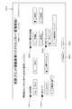
生成する分析モデルとして、例えば、行動ログの情報漏洩リスク分析モデルテーブル3300、機器稼働ログの情報漏洩リスク分析モデルテーブル3400がある。図33は、行動ログの情報漏洩リスク分析モデルテーブル3300のデータ構造例を示す説明図である。行動ログの情報漏洩リスク分析モデルテーブル3300は、開始時刻欄3310、終了時刻欄3320、社員ID欄3330、検出エリア欄3340、リスク発生時刻欄3350、リスク消滅時刻欄3360、リスク評価最大値欄3370を有している。開始時刻欄3310から検出エリア欄3340は、行動ログテーブル2600の開始時刻欄2610から検出エリア欄2640に該当し、それぞれ取得した開始時刻、終了時刻、社員ID、検出エリアを記憶する。リスク発生時刻欄3350からリスク評価最大値欄3370が分析モデルとして付加するものである。リスク発生時刻欄3350は、開始時刻欄2610に記憶されている開始時刻から予め定められた期間前(この場合は、3分)である日時を記憶する。リスク消滅時刻欄3360は、終了時刻欄2620に記憶されている終了時刻から予め定められた期間後である日時を記憶する。リスク評価最大値欄3370は、事象による影響を算出するための影響情報であるリスク評価最大値を記憶する。 As an analysis model to be generated, for example, there is an information leakage risk analysis model table 3300 for an action log and an information leakage risk analysis model table 3400 for an equipment operation log. FIG. 33 is an explanatory diagram showing an example of the data structure of the information leakage risk analysis model table 3300 of the action log. The action log information leakage risk analysis model table 3300 includes a
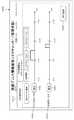
図34は、機器稼働ログの情報漏洩リスク分析モデルテーブル3400のデータ構造例を示す説明図である。機器稼働ログの情報漏洩リスク分析モデルテーブル3400は、放置開始時刻欄3410、放置終了時刻欄3420、ドキュメントID欄3430、プリント指示者ID欄3440、プリンタID欄3450、設置エリア欄3460、リスク発生時刻欄3470、リスク消滅時刻欄3480、リスク評価最大値欄3490を有している。放置開始時刻欄3410からプリンタID欄3450は、プリントログテーブル2900の放置開始時刻欄2910からプリンタID欄2950に該当し、それぞれ取得した放置開始時刻、放置終了時刻、ドキュメントID、プリント指示者ID、プリンタIDを記憶する。設置エリア欄3460からリスク評価最大値欄3490が分析モデルとして付加するものである。設置エリア欄3460は、プリンタ情報テーブル2800を用いて、プリンタID欄3450にある画像出力装置が設置されているエリアを記憶する。リスク発生時刻欄3470は、放置開始時刻欄2910に記憶されている開始時刻から予め定められた期間前(この場合は、1分)である日時を記憶する。リスク消滅時刻欄3480は、放置終了時刻欄2920に記憶されている終了時刻から予め定められた期間後(この場合は、0秒)である日時を記憶する。リスク評価最大値欄3490は、事象による影響を算出するための影響情報であるリスク評価最大値を記憶する。 FIG. 34 is an explanatory diagram showing an example of the data structure of the information leakage risk analysis model table 3400 of the device operation log. The information leakage risk analysis model table 3400 of the device operation log includes a leaving
ステップS2512では、分析結果生成モジュール124が、分析結果を生成する。例えば、画像出力装置のリスク評価値は、図32の例に示すようなグラフになっている。画像出力装置が印刷を開始した時刻(ts’)から印刷が終了した時刻(ts、放置開始時刻)まで、リスク評価値は増加する。印刷が終了した時刻(ts、放置開始時刻)から印刷媒体が回収された時刻(te、放置終了時刻)までは、その文書が放置された場合のリスク評価最大値となる。印刷媒体が回収された時刻(te、放置終了時刻)から予め定められた時間の後(te’)までは、リスク評価値は減少する。なお、画像出力装置が印刷を開始した時刻(ts’)から印刷が終了した時刻(ts、放置開始時刻)までの時間は、印刷する文書の枚数、画像出力装置の能力に基づいて計算し得る。なお、その画像出力装置があるエリアに入室した者が属している組織(個人属性情報テーブル2700)と出力した文書の開示範囲(情報媒体情報テーブル3000)との組み合わせから、リスク評価最大値(リスク評価最大値判定テーブル3100)が決定される。
そして、画像出力装置の出力結果を盗み見ることによる情報漏洩のリスク値は、画像出力装置の分析モデルとその画像出力装置があるエリアにいた利用者のリスク分析モデルの時間軸上で重なった時間におけるリスク評価最大値(行動ログの情報漏洩リスク分析モデルテーブル3300のリスク評価最大値欄3370と機器稼働ログの情報漏洩リスク分析モデルテーブル3400のリスク評価最大値欄3490)の積を算出する。他には分析モデルが重なった部分の面積を求めてもよい。In step S2512, the analysis
And the risk value of information leakage due to snooping the output result of the image output device is the time when the analysis model of the image output device and the risk analysis model of the user who was in the area where the image output device overlaps on the time axis The product of the risk assessment maximum value (the risk assessment
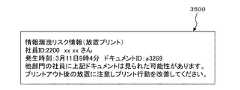
ステップS2514では、結果提示モジュール130が、分析結果を提示する。例えば、図35に示す分析結果通知画面3500を、画像出力装置のタッチパネル、出力の指示を行ったPC等の情報処理装置の表示装置を通じて、プリント指示者に提示する。 In step S2514, the
図36は、第2−Bの実施の形態の構成例についての概念的なモジュール構成図である。情報処理装置3600は、ログ情報取得モジュール110、分析モジュール120、個人属性情報取得モジュール2410、情報媒体情報取得モジュール2420、分析結果集約モジュール1610、結果提示モジュール130を有している。なお、第2−Aの実施の形態と同種の部位には同一符号を付し重複した説明を省略する(以下、同様)。
前述の第2−Aの実施の形態の利用者は、出力指示を行った一般の利用者であり、その利用者本人のリスクの分析結果を提示するものであった。第2−Bの実施の形態の利用者は管理者であり、特定の者のリスクの分析結果を提示するものではなく、例えば、ある組織に属している者達のリスクの分析結果を提示するものである。FIG. 36 is a conceptual module configuration diagram illustrating a configuration example of the 2-B embodiment. The
The user in the above-described second-A embodiment is a general user who has given an output instruction, and presents the analysis result of the user's own risk. The user of the embodiment 2-B is an administrator and does not present the analysis result of the risk of a specific person, for example, presents the analysis result of the risk of those belonging to a certain organization Is.
そのために、情報処理装置3600は、管理者3699によるマウス、キーボード、タッチパネル等の操作によって、操作指示である分析条件、分析開始要求又は集約条件変更を取得する。
分析結果集約モジュール1610は、分析モジュール120、結果提示モジュール130と接続されており、その管理者3699の操作指示に基づいて、分析結果生成モジュール124による分析結果を集計する。例えば、期間、対象としている人が属している組織、画像出力装置が設置されているエリア、印刷した文書のいずれか1つ又はこれらの組み合わせに基づいて、集計してもよい。For this purpose, the
The analysis
図37は、第2−Bの実施の形態による処理例を示すフローチャートである。なお、図25に示した第2−Aの実施の形態による処理例のフローチャートと同じ処理の場合は、図25の例に示したステップを示して、説明を省略する。
ステップS3702では、情報処理装置3600が、分析開始要求を取得する。ステップS2502と同等の処理である。
ステップS3704では、情報処理装置3600が、分析条件設定を取得する。管理者3699によるマウス、キーボード、タッチパネル等の操作によって、分析条件設定を取得する。分析条件として、期間、対象としている人が属している組織、画像出力装置が設置されているエリア、印刷した文書のいずれか1つ又はこれらの組み合わせであってもよい。図38は、分析条件設定画面3800の例を示す説明図である。分析条件設定画面3800は、分析期間設定欄3810、分析印刷指示組織設定欄3820、分析エリア設定欄3830、分析ドキュメントID設定欄3840、分析開始ボタン3850、リセットボタン3860を有している。分析条件設定画面3800は、分析期間設定欄3810は、分析対象となる期間を設定するための欄である。分析印刷指示組織設定欄3820は、印刷指示を行った者が属している分析対象となる組織を設定するための欄である。分析エリア設定欄3830は、画像出力装置が設置されている分析対象となるエリアを設定するための欄である。分析ドキュメントID設定欄3840は、出力された電子文書を設定するための欄である。分析開始ボタン3850が選択されたときの分析期間設定欄3810、分析印刷指示組織設定欄3820、分析エリア設定欄3830、分析ドキュメントID設定欄3840の設定に基づいて、分析条件設定を取得する。なお、期間、エリア、組織、ドキュメントIDの他に、出力指示を行った利用者の職種・職階、プリンタID、ドキュメント開示範囲、ドキュメント種別等も分析条件として設定するようにしてもよい。FIG. 37 is a flowchart illustrating an exemplary process according to the second 2-B embodiment. In the case of the same processing as the flowchart of the processing example according to the 2-A embodiment shown in FIG. 25, the steps shown in the example of FIG.
In step S3702, the
In step S3704, the
ステップS3706では、ログ情報取得モジュール110が、ログ情報を取得する。ステップS2504と同等の処理である。
ステップS3708では、個人属性情報取得モジュール2410が、個人属性情報を取得する。ステップS2506と同等の処理である。
ステップS3710では、情報媒体情報取得モジュール2420が、情報媒体情報を取得する。ステップS2508と同等の処理である。
ステップS3712では、分析モデル生成モジュール122が、分析モデルを生成する。ステップS2510と同等の処理である。
ステップS3714では、分析結果生成モジュール124が、分析結果を生成する。ステップS2512と同等の処理である。In step S3706, the log
In step S3708, the personal attribute
In step S3710, the information medium
In step S3712, the analysis
In step S3714, the analysis
ステップS3716では、分析結果を集約する。ステップS3704で取得した分析条件に基づいて、分析結果を集計している。
ステップS3718では、結果提示モジュール130が、分析結果を提示する。例えば、図39に例示する放置プリントによる情報漏洩の事後評価画面3900のように、管理者3699が操作し得る情報処理装置の表示装置に提示する。図39は、放置プリントによる情報漏洩の事後評価画面3900の例を示す説明図である。放置プリントによる情報漏洩の事後評価画面3900は、リスク分析条件を提示する分析期間表示領域3910、分析エリア表示領域3920、分析組織表示領域3930と、リスク評価結果を提示する放置プリント発生件数表示領域3940、放置プリント発生リスト3950と、再集約ボタン3980、閉じるボタン3990を有している。分析期間表示領域3910、分析エリア表示領域3920、分析組織表示領域3930は、ステップS3704で取得した分析条件(図38に例示した分析期間設定欄3810、分析エリア設定欄3830、分析印刷指示組織設定欄3820に該当)を提示する欄である。もちろんのことながら、分析対象としてドキュメントID(図38に例示した分析ドキュメントID設定欄3840に該当)を提示する欄を設けてもよい。放置プリント発生件数表示領域3940は、出力後にすぐに回収されていない状態となった件数を表示する欄であり、具体的には、分析条件に合致するプリントログテーブル2900内の件数である。放置プリント発生リスト3950は、放置プリント発生件数表示領域3940の案件の詳細を提示するものであり、印刷指示時刻欄3952、印刷指示社員ID欄3954、所属欄3956、プリンタID欄3958、設置エリア欄3960、ドキュメントID欄3962、開示範囲欄3964、情報取得社員ID欄3966、所属欄3968、情報漏洩リスク値欄3970を有している。また、各欄毎に、ソートによる並べ替え、条件に合致するものを取り出すフィルタリング等の処理を行えるようにしてもよい。In step S3716, the analysis results are collected. Based on the analysis conditions acquired in step S3704, the analysis results are tabulated.
In step S3718, the
ステップS3720では、集約条件が変更されたか否かを判断し、変更された場合はステップS3716からの処理を行い、それ以外の場合は処理を終了する(ステップS3799)。例えば、図39に例示の分析期間表示領域3910、分析エリア表示領域3920、分析組織表示領域3930には変更ボタンがあるが、この変更ボタンが選択された場合は、これらの分析条件を変更できるような表示を行う。そして、分析条件が変更された後に再集約ボタン3980が選択された場合が、集約条件が変更された場合に該当する。 In step S3720, it is determined whether or not the aggregation condition has been changed. If the aggregation condition has been changed, the process from step S3716 is performed. Otherwise, the process ends (step S3799). For example, the analysis
図40は、第2−Cの実施の形態の構成例についての概念的なモジュール構成図である。情報処理装置4000は、ログ情報取得モジュール110、ログ情報修正モジュール2010、スケジュール情報記憶モジュール2020、分析モジュール120、個人属性情報取得モジュール2410、情報媒体情報取得モジュール2420、分析結果集約モジュール1610、結果提示モジュール130を有している。
第2−Cの実施の形態は、過去の行動ログデータ、画像出力装置のログデータを変更してシミュレーションをすること、又は将来の予定であるスケジュール情報(例えば、利用者が画像出力装置が設置されているエリアに入室すること、利用者が会議に用いる資料を印刷すること等)を用いてシミュレーションをするものである。FIG. 40 is a conceptual module configuration diagram illustrating a configuration example of the 2-C embodiment. The
In the second-C embodiment, simulation is performed by changing past action log data and log data of the image output apparatus, or schedule information that is a future plan (for example, the user installs the image output apparatus) The user enters a designated area, prints materials used by the user for the conference, etc.).
ログ情報修正モジュール2010は、分析モジュール120、スケジュール情報記憶モジュール2020と接続されている。ログ情報修正モジュール2010は、屋内行動ログDB2312又は機器稼働ログDB2314に記憶されている事象の開始日時、その事象の終了日時、その事象が発生した場所を少なくとも含む事象の行動ログデータの内、いずれか1つ又はこれらの組み合わせを修正する。また、利用者又は画像出力装置の将来の予定である事象の開始日時、その事象の終了日時、その事象が発生する場所を少なくとも含む事象の予定情報を記憶するスケジュール情報記憶モジュール2020から対象とする利用者又は画像出力装置の予定情報を付加する修正を行うようにしてもよい。なお、修正には、既に屋内行動ログDB2312又は機器稼働ログDB2314に記憶されているログデータを変更、削除することの他、新たに予定情報から生成される情報をログデータとして付加することを含む。
スケジュール情報記憶モジュール2020は、ログ情報修正モジュール2010と接続されている。スケジュール情報記憶モジュール2020は、スケジュール情報である利用者又は画像出力装置の将来の予定である事象の開始日時、その事象の終了日時、その事象が発生する場所を少なくとも含む情報を記憶する。また、図5に例示したスケジュールDB520、スケジュール情報管理サーバホスト515を図23に例示するシステム構成例に付加して、スケジュールDB520にスケジュール情報を記憶させてもよい。そして、スケジュール情報記憶モジュール2020内の情報は、スケジュールDB520から取得する。The log
The schedule
図41は、第2−Cの実施の形態による処理例を示すフローチャートである。なお、図37に示した第2−Bの実施の形態による処理例のフローチャートと同じ処理の場合は、図37の例に示したステップを示して、説明を省略する。
ステップS4102では、情報処理装置4000が、分析開始要求を取得する。ステップS3702と同等の処理である。
ステップS4104では、情報処理装置4000が、分析条件設定を取得する。ステップS3704と同等の処理である。
ステップS4106では、ログ情報取得モジュール110が、ログ情報を取得する。ステップS3706と同等の処理である。
ステップS4108では、個人属性情報取得モジュール2410が、個人属性情報を取得する。ステップS3708と同等の処理である。
ステップS4110では、情報媒体情報取得モジュール2420が、情報媒体情報を取得する。ステップS3710と同等の処理である。FIG. 41 is a flowchart illustrating a processing example according to the second-C embodiment. In the case of the same process as the flowchart of the process example according to the second-B embodiment shown in FIG. 37, the steps shown in the example of FIG.
In step S4102, the
In step S4104, the
In step S4106, the log
In step S4108, the personal attribute
In step S4110, the information medium
ステップS4112では、ログ情報修正モジュール2010が、ログ情報を修正する。管理者4099によるマウス、キーボード、タッチパネル等の操作によって、シミュレーション条件を受け付け、屋内行動ログDB2312又は機器稼働ログDB2314内のログデータを修正する。シミュレーション条件の設定用の画面として、例えば、放置プリント情報漏洩リスクシミュレーション画面4200がある。図42は、放置プリント情報漏洩リスクシミュレーション画面4200の例を示す説明図である。放置プリント情報漏洩リスクシミュレーション画面4200は、分析条件設定タブ4210、ログ情報修正(シミュレーション)タブ4220を有している。ログ情報修正(シミュレーション)タブ4220は、対象とする画像出力装置又は利用者の過去のログデータを提示する対象プリンタ(P001)ログ表示領域4222、対象社員(1230)ログ表示領域4224があり、それらのログデータを修正するための修正ボタン4226、修正ボタン4228があり、新たにスケジュール情報から行動ログデータを追加するためのログ追加ボタン4290を有している。図42の例では、利用者の部屋への入室日時、退室日時、画像出力装置の放置開始日時、放置終了日時を変更し得るようになっているが、この他にその部屋、画像出力装置等を変更し得るようにしてもよい。また、ログ追加ボタン4290が選択された場合は、ログ情報修正モジュール2010は、スケジュール情報記憶モジュール2020から対象とする利用者又は画像出力装置のスケジュール情報を取り出して、ログデータとして追加する。 In step S4112, the log
ステップS4114では、分析モデル生成モジュール122が、分析モデルを生成する。ステップS3712と同等の処理である。
ステップS4116では、分析結果生成モジュール124が、分析結果を生成する。ステップS3714と同等の処理である。
ステップS4118では、分析結果集約モジュール1610が、分析結果を集約する。ステップS3716と同等の処理である。
ステップS4120では、結果提示モジュール130が、分析結果を提示する。ステップS3718と同等の処理である。
ステップS4122では、分析結果集約モジュール1610が、集約条件が変更されたか否かを判断し、変更された場合はステップS4118からの処理を行い、それ以外の場合はステップS4124へ進む。ステップS3720と同等の処理である。
ステップS4124では、ログ情報修正モジュール2010が、分析条件が変更されたか否かを判断し、変更された場合はステップS4104からの処理を行い、それ以外の場合は処理を終了する(ステップS4199)。In step S4114, the analysis
In step S4116, the analysis
In step S4118, the analysis
In step S4120, the
In step S412, the analysis
In step S4124, the log
なお、第2−Cの実施の形態では、図40に例示するように分析結果集約モジュール1610を用いたが、分析結果集約モジュール1610がなく、分析モジュール120と結果提示モジュール130が接続されていてもよい。そして、第2−Aの実施の形態にように、管理者4099ではなく、一般の利用者によって使用されてもよい。
また、第2の実施の形態(第2−Aの実施の形態、第2−Bの実施の形態、第2−Cの実施の形態を含む)では、画像出力装置の例として、プリンタ、複合機を示したが、複写機、ファックス等であってもよい。
また、画像出力装置の稼働ログとして、利用者が操作可能なPC等の情報処理装置の表示装置上での電子文書が開かれた時間と、閉じられた時間と、その情報処理装置が設置されている場所、そのドキュメントIDとからなるログと、人の位置情報と、情報媒体情報と、個人属性情報とを用いることで前述の放置プリントと同様に表示装置の盗み見による情報漏洩リスクを分析するようにしてもよい。In the second-C embodiment, the analysis
In the second embodiment (including the 2-A embodiment, the 2-B embodiment, and the 2-C embodiment), as an example of the image output device, a printer, a composite Although a machine is shown, it may be a copier, a fax machine, or the like.
In addition, as the operation log of the image output device, the time when the electronic document is opened and closed on the display device of the information processing device such as a PC that can be operated by the user, and the information processing device are installed. The information leakage risk due to the snooping of the display device is analyzed in the same way as the above-mentioned neglected print by using the log including the location, the document ID, the person's position information, the information medium information, and the personal attribute information. You may do it.
なお、本実施の形態としてのプログラムが実行されるコンピュータのハードウェア構成は、図43に例示するように、一般的なコンピュータであり、具体的にはパーソナルコンピュータ、サーバとなり得るコンピュータ等である。つまり、具体例として、処理部(演算部)としてCPU4301を用い、記憶装置としてRAM4302、ROM4303、HD4304を用いている。HD4304として、例えばハードディスクを用いてもよい。ログ情報取得モジュール110、分析モデル生成モジュール122、分析結果生成モジュール124、結果提示モジュール130、分析結果集約モジュール1610、ログ情報修正モジュール2010、個人属性情報取得モジュール2410、情報媒体情報取得モジュール2420等のプログラムを実行するCPU4301と、そのプログラムやデータを記憶するRAM4302と、本コンピュータを起動するためのプログラム等が格納されているROM4303と、補助記憶装置であるHD4304と、キーボード、マウス、タッチパネル等に対する利用者の操作に基づいてデータを受け付ける受付装置4306と、CRT、液晶ディスプレイ等の出力装置4305と、ネットワークインタフェースカード等の通信ネットワークと接続するための通信回線インタフェース4307、そして、それらをつないでデータのやりとりをするためのバス4308により構成されている。これらのコンピュータが複数台互いにネットワークによって接続されていてもよい。 Note that the hardware configuration of the computer on which the program according to the present embodiment is executed is a general computer as illustrated in FIG. 43, specifically, a personal computer, a computer that can be a server, or the like. That is, as a specific example, a
前述の実施の形態の内、コンピュータ・プログラムによるものについては、本ハードウェア構成のシステムにソフトウェアであるコンピュータ・プログラムを読み込ませ、ソフトウェアとハードウェア資源とが協働して、前述の実施の形態が実現される。
なお、図43に示すハードウェア構成は、1つの構成例を示すものであり、本実施の形態は、図43に示す構成に限らず、本実施の形態において説明したモジュールを実行可能な構成であればよい。例えば、一部のモジュールを専用のハードウェア(例えばASIC等)で構成してもよく、一部のモジュールは外部のシステム内にあり通信回線で接続しているような形態でもよく、さらに図43に示すシステムが複数互いに通信回線によって接続されていて互いに協調動作するようにしてもよい。また、特に、パーソナルコンピュータの他、情報家電、複写機、ファックス、スキャナ、プリンタ、複合機などに組み込まれていてもよい。Among the above-described embodiments, for the computer program, the system having the hardware configuration is loaded with a computer program that is software, and the software and hardware resources cooperate to cause the above-described embodiment. Is realized.
Note that the hardware configuration illustrated in FIG. 43 illustrates one configuration example, and the present embodiment is not limited to the configuration illustrated in FIG. 43, and is a configuration that can execute the modules described in the present embodiment. I just need it. For example, some modules may be configured by dedicated hardware (for example, ASIC), and some modules may be in an external system and connected via a communication line. A plurality of systems shown in FIG. 5 may be connected to each other via communication lines so as to cooperate with each other. In particular, in addition to a personal computer, it may be incorporated in an information appliance, a copier, a fax machine, a scanner, a printer, a multifunction machine, or the like.
なお、説明したプログラムについては、記録媒体に格納して提供してもよく、また、そのプログラムを通信手段によって提供してもよい。その場合、例えば、前記説明したプログラムについて、「プログラムを記録したコンピュータ読み取り可能な記録媒体」の発明として捉えてもよい。
「プログラムを記録したコンピュータ読み取り可能な記録媒体」とは、プログラムのインストール、実行、プログラムの流通などのために用いられる、プログラムが記録されたコンピュータで読み取り可能な記録媒体をいう。
なお、記録媒体としては、例えば、デジタル・バーサタイル・ディスク(DVD)であって、DVDフォーラムで策定された規格である「DVD−R、DVD−RW、DVD−RAM等」、DVD+RWで策定された規格である「DVD+R、DVD+RW等」、コンパクトディスク(CD)であって、読出し専用メモリ(CD−ROM)、CDレコーダブル(CD−R)、CDリライタブル(CD−RW)等、ブルーレイ・ディスク(Blu−ray Disc(登録商標))、光磁気ディスク(MO)、フレキシブルディスク(FD)、磁気テープ、ハードディスク、読出し専用メモリ(ROM)、電気的消去及び書換可能な読出し専用メモリ(EEPROM)、フラッシュ・メモリ、ランダム・アクセス・メモリ(RAM)等が含まれる。
そして、前記のプログラム又はその一部は、前記記録媒体に記録して保存や流通等させてもよい。また、通信によって、例えば、ローカル・エリア・ネットワーク(LAN)、メトロポリタン・エリア・ネットワーク(MAN)、ワイド・エリア・ネットワーク(WAN)、インターネット、イントラネット、エクストラネット等に用いられる有線ネットワーク、あるいは無線通信ネットワーク、さらにこれらの組み合わせ等の伝送媒体を用いて伝送させてもよく、また、搬送波に乗せて搬送させてもよい。
さらに、前記のプログラムは、他のプログラムの一部分であってもよく、あるいは別個のプログラムと共に記録媒体に記録されていてもよい。また、複数の記録媒体に分割して
記録されていてもよい。また、圧縮や暗号化など、復元可能であればどのような態様で記録されていてもよい。The program described above may be provided by being stored in a recording medium, or the program may be provided by communication means. In that case, for example, the above-described program may be regarded as an invention of a “computer-readable recording medium recording the program”.
The “computer-readable recording medium on which a program is recorded” refers to a computer-readable recording medium on which a program is recorded, which is used for program installation, execution, program distribution, and the like.
The recording medium is, for example, a digital versatile disc (DVD), which is a standard established by the DVD Forum, such as “DVD-R, DVD-RW, DVD-RAM,” and DVD + RW. Standard “DVD + R, DVD + RW, etc.”, compact disc (CD), read-only memory (CD-ROM), CD recordable (CD-R), CD rewritable (CD-RW), Blu-ray disc ( Blu-ray Disc (registered trademark), magneto-optical disk (MO), flexible disk (FD), magnetic tape, hard disk, read-only memory (ROM), electrically erasable and rewritable read-only memory (EEPROM), flash Includes memory, random access memory (RAM), etc. .
The program or a part of the program may be recorded on the recording medium for storage or distribution. Also, by communication, for example, a local area network (LAN), a metropolitan area network (MAN), a wide area network (WAN), a wired network used for the Internet, an intranet, an extranet, etc., or wireless communication It may be transmitted using a transmission medium such as a network or a combination of these, or may be carried on a carrier wave.
Furthermore, the program may be a part of another program, or may be recorded on a recording medium together with a separate program. Moreover, it may be divided and recorded on a plurality of recording media. Further, it may be recorded in any manner as long as it can be restored, such as compression or encryption.
100…情報処理装置
110…ログ情報取得モジュール
120…分析モジュール
122…分析モデル生成モジュール
124…分析結果生成モジュール
130…結果提示モジュール
505…ログDBサーバホスト
510…屋内行動ログDB
515…スケジュール情報管理サーバホスト
520…スケジュールDB
525…位置情報サーバホスト
530…位置センサ
535…分析サーバホスト
540…エリア特性DB
545…個人属性情報DB
550…感染リスクDB
555…感染状態DB
560…分析クライアントホスト
585…タグ
599…通信回線
1600…情報処理装置
1610…分析結果集約モジュール
2000…情報処理装置
2010…ログ情報修正モジュール
2020…スケジュール情報記憶モジュール
2310…ログDBサーバホスト
2312…屋内行動ログDB
2314…機器稼働ログDB
2320…分析サーバホスト
2322…個人属性情報DB
2324…エリア特性DB
2326…情報媒体情報DB
2328…プリンタ情報DB
2330…位置情報サーバホスト
2335…位置センサ
2340…機器稼働情報サーバホスト
2342…PC
2344…複合機
2350…分析クライアントホスト
2385…タグ
2399…通信回線
2400…情報処理装置
2410…個人属性情報取得モジュール
2420…情報媒体情報取得モジュールDESCRIPTION OF
515 ... schedule information
525 ... Position information server host 530 ...
545 ... Personal attribute information DB
550 ... Risk DB
555 ... Infectious state DB
560 ...
2314 ... Equipment operation log DB
2320 ...
2324 ... Area characteristic DB
2326 ... Information medium information DB
2328 ... Printer information DB
2330 ... Position information server host 2335 ...
2344 ...
Claims (5)
Translated fromJapanese前記取得手段によって取得された事象の記録情報内の開始日時または前記開始日時から予め定められた期間前もしくは期間後である日時をモデルの開始日時とし、該事象の記録情報内の終了日時から予め定められた期間前又は期間後である日時をモデルの終了日時とし、該事象による影響を算出するための影響情報を少なくとも含むモデルを生成するモデル生成手段と、
前記モデル生成手段によって生成された第1の事象のモデルの開始日時及び終了日時により定まる期間と前記モデル生成手段によって生成された第2の事象のモデルの開始日時及び終了日時により定まる期間が重複する期間と、該第1の事象のモデルの影響情報又は該第2の事象のモデルの影響情報に基づいて、該第1の事象と該第2の事象間の影響を分析する分析手段と、
前記事象記録情報記憶装置に記憶されている事象の開始日時、該事象の終了日時、該事象が発生した場所を少なくとも含む事象の記録情報の内、いずれか1つ又はこれらの組み合わせを修正する修正手段
を具備し、
前記第2の事象は、前記第1の事象が発生した場所と同じ場所で発生した事象であり、
前記モデル生成手段は、前記事象記録情報記憶装置内の前記修正手段によって修正された事象のモデルを生成する
ことを特徴とする情報処理装置。An acquisition means for acquiring record information of a target event from an event record information storage device that stores record information of an event including at least a start date and time of the event, an end date and time of the event, and a place where the event has occurred;
The start date/ time in the event record information acquired by the acquisition meansor the date/ time beforeor after a predetermined period from the start date / time as the model start date / time, and the end date / time in the event record information Model generation means for generating a model including at least impact information for calculating the influence of the event, with the date and time before or after the set period as the end date and time of the model,
The period determined by the start date / time and end date / time of the first event model generated by the model generation means overlaps with the period determined by the start date / time and end date / time of the second event model generated by the model generation means. Analyzing means for analyzing an influence between the first event and the second event based on a period and the effect information of the model of the first event or the effect information of the model of the second event;
Modify one or a combination of the event record information including at least the event start date and time, the event end date and time, and the location where the event occurred, stored in the event record information storage device. Havingcorrection means ,
The second event,Ri event der occurring at the same location where the first event hasoccurred,
The information processing apparatus, wherein the model generation unit generates a model of the event corrected by the correction unit in the event record information storage device.
をさらに具備することを特徴とする請求項1に記載の情報処理装置。The information processing apparatus according to claim 1, further comprising output means for outputting an analysis result by the analysis means.
をさらに具備する
ことを特徴とする請求項1又は2に記載の情報処理装置。The information processing apparatus according to claim 1, further comprising: a totaling unit that totalizes the analysis results by the analysis unit based on a user's operation instruction.
ことを特徴とする請求項1から3のいずれか一項に記載の情報処理装置。The correction means is a target user from a schedule information storage means for storing schedule information of an event including at least a start date and time of an event that is a user's future schedule, an end date and time of the event, and a place where the event occurs. The information processing apparatus according to any one of claims 1 to3 , wherein a correction for adding the schedule information is performed.
事象の開始日時、該事象の終了日時、該事象が発生した場所を少なくとも含む事象の記録情報を記憶する事象記録情報記憶装置から対象とする事象の記録情報を取得する取得手段と、
前記取得手段によって取得された事象の記録情報内の開始日時または前記開始日時から予め定められた期間前もしくは期間後である日時をモデルの開始日時とし、該事象の記録情報内の終了日時から予め定められた期間前又は期間後である日時をモデルの終了日時とし、該事象による影響を算出するための影響情報を少なくとも含むモデルを生成するモデル生成手段と、
前記モデル生成手段によって生成された第1の事象のモデルの開始日時及び終了日時により定まる期間と前記モデル生成手段によって生成された第2の事象のモデルの開始日時及び終了日時により定まる期間が重複する期間と、該第1の事象のモデルの影響情報又は該第2の事象のモデルの影響情報に基づいて、該第1の事象と該第2の事象間の影響を分析する分析手段と、
前記事象記録情報記憶装置に記憶されている事象の開始日時、該事象の終了日時、該事象が発生した場所を少なくとも含む事象の記録情報の内、いずれか1つ又はこれらの組み合わせを修正する修正手段
として機能させ、
前記第2の事象は、前記第1の事象が発生した場所と同じ場所で発生した事象であり、
前記モデル生成手段は、前記事象記録情報記憶装置内の前記修正手段によって修正された事象のモデルを生成する
ことを特徴とする情報処理プログラム。Computer
An acquisition means for acquiring record information of a target event from an event record information storage device that stores record information of an event including at least a start date and time of the event, an end date and time of the event, and a place where the event has occurred;
The start date/ time in the event record information acquired by the acquisition meansor the date/ time beforeor after a predetermined period from the start date / time as the model start date / time, and the end date / time in the event record information Model generation means for generating a model including at least impact information for calculating the influence of the event, with the date and time before or after the set period as the end date and time of the model,
The period determined by the start date / time and end date / time of the first event model generated by the model generation means overlaps with the period determined by the start date / time and end date / time of the second event model generated by the model generation means. Analyzing means for analyzing an influence between the first event and the second event based on a period and the effect information of the model of the first event or the effect information of the model of the second event;
Modify one or a combination of the event record information including at least the event start date and time, the event end date and time, and the location where the event occurred, stored in the event record information storage device. Function as acorrection means ,
The second event,Ri event der occurring at the same location where the first event hasoccurred,
The information processing program, wherein the model generation means generates a model of an event corrected by the correction means in the event record information storage device .
Priority Applications (3)
| Application Number | Priority Date | Filing Date | Title |
|---|---|---|---|
| JP2010184506AJP5633245B2 (en) | 2010-08-20 | 2010-08-20 | Information processing apparatus and information processing program |
| US13/023,936US8914263B2 (en) | 2010-08-20 | 2011-02-09 | Information processing apparatus, information processing method and computer readable medium for assessment of event influence |
| CN201110070303.7ACN102375924B (en) | 2010-08-20 | 2011-03-18 | Information processor and information processing method |
Applications Claiming Priority (1)
| Application Number | Priority Date | Filing Date | Title |
|---|---|---|---|
| JP2010184506AJP5633245B2 (en) | 2010-08-20 | 2010-08-20 | Information processing apparatus and information processing program |
Publications (2)
| Publication Number | Publication Date |
|---|---|
| JP2012043231A JP2012043231A (en) | 2012-03-01 |
| JP5633245B2true JP5633245B2 (en) | 2014-12-03 |
Family
ID=45594756
Family Applications (1)
| Application Number | Title | Priority Date | Filing Date |
|---|---|---|---|
| JP2010184506AExpired - Fee RelatedJP5633245B2 (en) | 2010-08-20 | 2010-08-20 | Information processing apparatus and information processing program |
Country Status (2)
| Country | Link |
|---|---|
| US (1) | US8914263B2 (en) |
| JP (1) | JP5633245B2 (en) |
Families Citing this family (178)
| Publication number | Priority date | Publication date | Assignee | Title |
|---|---|---|---|---|
| US9729583B1 (en) | 2016-06-10 | 2017-08-08 | OneTrust, LLC | Data processing systems and methods for performing privacy assessments and monitoring of new versions of computer code for privacy compliance |
| US10289867B2 (en)* | 2014-07-27 | 2019-05-14 | OneTrust, LLC | Data processing systems for webform crawling to map processing activities and related methods |
| US10181051B2 (en) | 2016-06-10 | 2019-01-15 | OneTrust, LLC | Data processing systems for generating and populating a data inventory for processing data access requests |
| JP2016177550A (en)* | 2015-03-20 | 2016-10-06 | 株式会社リコー | Information processing apparatus, program, output system, and output method |
| US12288233B2 (en) | 2016-04-01 | 2025-04-29 | OneTrust, LLC | Data processing systems and methods for integrating privacy information management systems with data loss prevention tools or other tools for privacy design |
| US11004125B2 (en) | 2016-04-01 | 2021-05-11 | OneTrust, LLC | Data processing systems and methods for integrating privacy information management systems with data loss prevention tools or other tools for privacy design |
| US10423996B2 (en) | 2016-04-01 | 2019-09-24 | OneTrust, LLC | Data processing systems and communication systems and methods for the efficient generation of privacy risk assessments |
| US10706447B2 (en) | 2016-04-01 | 2020-07-07 | OneTrust, LLC | Data processing systems and communication systems and methods for the efficient generation of privacy risk assessments |
| US11244367B2 (en) | 2016-04-01 | 2022-02-08 | OneTrust, LLC | Data processing systems and methods for integrating privacy information management systems with data loss prevention tools or other tools for privacy design |
| US10585968B2 (en) | 2016-06-10 | 2020-03-10 | OneTrust, LLC | Data processing systems for fulfilling data subject access requests and related methods |
| US10282559B2 (en) | 2016-06-10 | 2019-05-07 | OneTrust, LLC | Data processing systems for identifying, assessing, and remediating data processing risks using data modeling techniques |
| US11294939B2 (en) | 2016-06-10 | 2022-04-05 | OneTrust, LLC | Data processing systems and methods for automatically detecting and documenting privacy-related aspects of computer software |
| US11341447B2 (en) | 2016-06-10 | 2022-05-24 | OneTrust, LLC | Privacy management systems and methods |
| US10496846B1 (en) | 2016-06-10 | 2019-12-03 | OneTrust, LLC | Data processing and communications systems and methods for the efficient implementation of privacy by design |
| US10949565B2 (en) | 2016-06-10 | 2021-03-16 | OneTrust, LLC | Data processing systems for generating and populating a data inventory |
| US11227247B2 (en) | 2016-06-10 | 2022-01-18 | OneTrust, LLC | Data processing systems and methods for bundled privacy policies |
| US10592692B2 (en) | 2016-06-10 | 2020-03-17 | OneTrust, LLC | Data processing systems for central consent repository and related methods |
| US10452864B2 (en) | 2016-06-10 | 2019-10-22 | OneTrust, LLC | Data processing systems for webform crawling to map processing activities and related methods |
| US10642870B2 (en) | 2016-06-10 | 2020-05-05 | OneTrust, LLC | Data processing systems and methods for automatically detecting and documenting privacy-related aspects of computer software |
| US10467432B2 (en) | 2016-06-10 | 2019-11-05 | OneTrust, LLC | Data processing systems for use in automatically generating, populating, and submitting data subject access requests |
| US10997315B2 (en) | 2016-06-10 | 2021-05-04 | OneTrust, LLC | Data processing systems for fulfilling data subject access requests and related methods |
| US10769301B2 (en) | 2016-06-10 | 2020-09-08 | OneTrust, LLC | Data processing systems for webform crawling to map processing activities and related methods |
| US10275614B2 (en) | 2016-06-10 | 2019-04-30 | OneTrust, LLC | Data processing systems for generating and populating a data inventory |
| US10885485B2 (en) | 2016-06-10 | 2021-01-05 | OneTrust, LLC | Privacy management systems and methods |
| US10798133B2 (en) | 2016-06-10 | 2020-10-06 | OneTrust, LLC | Data processing systems for data-transfer risk identification, cross-border visualization generation, and related methods |
| US11727141B2 (en) | 2016-06-10 | 2023-08-15 | OneTrust, LLC | Data processing systems and methods for synching privacy-related user consent across multiple computing devices |
| US11301796B2 (en) | 2016-06-10 | 2022-04-12 | OneTrust, LLC | Data processing systems and methods for customizing privacy training |
| US11416109B2 (en) | 2016-06-10 | 2022-08-16 | OneTrust, LLC | Automated data processing systems and methods for automatically processing data subject access requests using a chatbot |
| US10204154B2 (en) | 2016-06-10 | 2019-02-12 | OneTrust, LLC | Data processing systems for generating and populating a data inventory |
| US10416966B2 (en) | 2016-06-10 | 2019-09-17 | OneTrust, LLC | Data processing systems for identity validation of data subject access requests and related methods |
| US11138242B2 (en) | 2016-06-10 | 2021-10-05 | OneTrust, LLC | Data processing systems and methods for automatically detecting and documenting privacy-related aspects of computer software |
| US10430740B2 (en) | 2016-06-10 | 2019-10-01 | One Trust, LLC | Data processing systems for calculating and communicating cost of fulfilling data subject access requests and related methods |
| US11366786B2 (en) | 2016-06-10 | 2022-06-21 | OneTrust, LLC | Data processing systems for processing data subject access requests |
| US10592648B2 (en) | 2016-06-10 | 2020-03-17 | OneTrust, LLC | Consent receipt management systems and related methods |
| US11228620B2 (en) | 2016-06-10 | 2022-01-18 | OneTrust, LLC | Data processing systems for data-transfer risk identification, cross-border visualization generation, and related methods |
| US12045266B2 (en) | 2016-06-10 | 2024-07-23 | OneTrust, LLC | Data processing systems for generating and populating a data inventory |
| US10284604B2 (en) | 2016-06-10 | 2019-05-07 | OneTrust, LLC | Data processing and scanning systems for generating and populating a data inventory |
| US10909488B2 (en) | 2016-06-10 | 2021-02-02 | OneTrust, LLC | Data processing systems for assessing readiness for responding to privacy-related incidents |
| US10846433B2 (en) | 2016-06-10 | 2020-11-24 | OneTrust, LLC | Data processing consent management systems and related methods |
| US10713387B2 (en) | 2016-06-10 | 2020-07-14 | OneTrust, LLC | Consent conversion optimization systems and related methods |
| US11134086B2 (en) | 2016-06-10 | 2021-09-28 | OneTrust, LLC | Consent conversion optimization systems and related methods |
| US10783256B2 (en) | 2016-06-10 | 2020-09-22 | OneTrust, LLC | Data processing systems for data transfer risk identification and related methods |
| US10586075B2 (en) | 2016-06-10 | 2020-03-10 | OneTrust, LLC | Data processing systems for orphaned data identification and deletion and related methods |
| US10839102B2 (en) | 2016-06-10 | 2020-11-17 | OneTrust, LLC | Data processing systems for identifying and modifying processes that are subject to data subject access requests |
| US11210420B2 (en) | 2016-06-10 | 2021-12-28 | OneTrust, LLC | Data subject access request processing systems and related methods |
| US11562097B2 (en) | 2016-06-10 | 2023-01-24 | OneTrust, LLC | Data processing systems for central consent repository and related methods |
| US10565236B1 (en) | 2016-06-10 | 2020-02-18 | OneTrust, LLC | Data processing systems for generating and populating a data inventory |
| US10509920B2 (en) | 2016-06-10 | 2019-12-17 | OneTrust, LLC | Data processing systems for processing data subject access requests |
| US10510031B2 (en) | 2016-06-10 | 2019-12-17 | OneTrust, LLC | Data processing systems for identifying, assessing, and remediating data processing risks using data modeling techniques |
| US10440062B2 (en) | 2016-06-10 | 2019-10-08 | OneTrust, LLC | Consent receipt management systems and related methods |
| US10289870B2 (en) | 2016-06-10 | 2019-05-14 | OneTrust, LLC | Data processing systems for fulfilling data subject access requests and related methods |
| US11416590B2 (en) | 2016-06-10 | 2022-08-16 | OneTrust, LLC | Data processing and scanning systems for assessing vendor risk |
| US11354434B2 (en) | 2016-06-10 | 2022-06-07 | OneTrust, LLC | Data processing systems for verification of consent and notice processing and related methods |
| US10706131B2 (en) | 2016-06-10 | 2020-07-07 | OneTrust, LLC | Data processing systems and methods for efficiently assessing the risk of privacy campaigns |
| US11100444B2 (en) | 2016-06-10 | 2021-08-24 | OneTrust, LLC | Data processing systems and methods for providing training in a vendor procurement process |
| US10896394B2 (en) | 2016-06-10 | 2021-01-19 | OneTrust, LLC | Privacy management systems and methods |
| US10614247B2 (en) | 2016-06-10 | 2020-04-07 | OneTrust, LLC | Data processing systems for automated classification of personal information from documents and related methods |
| US11038925B2 (en) | 2016-06-10 | 2021-06-15 | OneTrust, LLC | Data processing systems for data-transfer risk identification, cross-border visualization generation, and related methods |
| US10353673B2 (en) | 2016-06-10 | 2019-07-16 | OneTrust, LLC | Data processing systems for integration of consumer feedback with data subject access requests and related methods |
| US11144622B2 (en) | 2016-06-10 | 2021-10-12 | OneTrust, LLC | Privacy management systems and methods |
| US11146566B2 (en) | 2016-06-10 | 2021-10-12 | OneTrust, LLC | Data processing systems for fulfilling data subject access requests and related methods |
| US10607028B2 (en) | 2016-06-10 | 2020-03-31 | OneTrust, LLC | Data processing systems for data testing to confirm data deletion and related methods |
| US10685140B2 (en) | 2016-06-10 | 2020-06-16 | OneTrust, LLC | Consent receipt management systems and related methods |
| US11238390B2 (en) | 2016-06-10 | 2022-02-01 | OneTrust, LLC | Privacy management systems and methods |
| US11392720B2 (en) | 2016-06-10 | 2022-07-19 | OneTrust, LLC | Data processing systems for verification of consent and notice processing and related methods |
| US11138299B2 (en) | 2016-06-10 | 2021-10-05 | OneTrust, LLC | Data processing and scanning systems for assessing vendor risk |
| US10708305B2 (en) | 2016-06-10 | 2020-07-07 | OneTrust, LLC | Automated data processing systems and methods for automatically processing requests for privacy-related information |
| US10289866B2 (en) | 2016-06-10 | 2019-05-14 | OneTrust, LLC | Data processing systems for fulfilling data subject access requests and related methods |
| US11651106B2 (en) | 2016-06-10 | 2023-05-16 | OneTrust, LLC | Data processing systems for fulfilling data subject access requests and related methods |
| US10346638B2 (en) | 2016-06-10 | 2019-07-09 | OneTrust, LLC | Data processing systems for identifying and modifying processes that are subject to data subject access requests |
| US11188615B2 (en) | 2016-06-10 | 2021-11-30 | OneTrust, LLC | Data processing consent capture systems and related methods |
| US10565161B2 (en) | 2016-06-10 | 2020-02-18 | OneTrust, LLC | Data processing systems for processing data subject access requests |
| US10848523B2 (en) | 2016-06-10 | 2020-11-24 | OneTrust, LLC | Data processing systems for data-transfer risk identification, cross-border visualization generation, and related methods |
| US11416589B2 (en) | 2016-06-10 | 2022-08-16 | OneTrust, LLC | Data processing and scanning systems for assessing vendor risk |
| US10496803B2 (en) | 2016-06-10 | 2019-12-03 | OneTrust, LLC | Data processing systems and methods for efficiently assessing the risk of privacy campaigns |
| US11222139B2 (en) | 2016-06-10 | 2022-01-11 | OneTrust, LLC | Data processing systems and methods for automatic discovery and assessment of mobile software development kits |
| US11636171B2 (en) | 2016-06-10 | 2023-04-25 | OneTrust, LLC | Data processing user interface monitoring systems and related methods |
| US10762236B2 (en) | 2016-06-10 | 2020-09-01 | OneTrust, LLC | Data processing user interface monitoring systems and related methods |
| US10706379B2 (en) | 2016-06-10 | 2020-07-07 | OneTrust, LLC | Data processing systems for automatic preparation for remediation and related methods |
| US12118121B2 (en) | 2016-06-10 | 2024-10-15 | OneTrust, LLC | Data subject access request processing systems and related methods |
| US11025675B2 (en) | 2016-06-10 | 2021-06-01 | OneTrust, LLC | Data processing systems and methods for performing privacy assessments and monitoring of new versions of computer code for privacy compliance |
| US10437412B2 (en) | 2016-06-10 | 2019-10-08 | OneTrust, LLC | Consent receipt management systems and related methods |
| US11074367B2 (en) | 2016-06-10 | 2021-07-27 | OneTrust, LLC | Data processing systems for identity validation for consumer rights requests and related methods |
| US10873606B2 (en) | 2016-06-10 | 2020-12-22 | OneTrust, LLC | Data processing systems for data-transfer risk identification, cross-border visualization generation, and related methods |
| US11200341B2 (en) | 2016-06-10 | 2021-12-14 | OneTrust, LLC | Consent receipt management systems and related methods |
| US11277448B2 (en) | 2016-06-10 | 2022-03-15 | OneTrust, LLC | Data processing systems for data-transfer risk identification, cross-border visualization generation, and related methods |
| US10565397B1 (en) | 2016-06-10 | 2020-02-18 | OneTrust, LLC | Data processing systems for fulfilling data subject access requests and related methods |
| US11157600B2 (en) | 2016-06-10 | 2021-10-26 | OneTrust, LLC | Data processing and scanning systems for assessing vendor risk |
| US11366909B2 (en) | 2016-06-10 | 2022-06-21 | OneTrust, LLC | Data processing and scanning systems for assessing vendor risk |
| US11151233B2 (en) | 2016-06-10 | 2021-10-19 | OneTrust, LLC | Data processing and scanning systems for assessing vendor risk |
| US10282692B2 (en) | 2016-06-10 | 2019-05-07 | OneTrust, LLC | Data processing systems for identifying, assessing, and remediating data processing risks using data modeling techniques |
| US10997318B2 (en) | 2016-06-10 | 2021-05-04 | OneTrust, LLC | Data processing systems for generating and populating a data inventory for processing data access requests |
| US10318761B2 (en) | 2016-06-10 | 2019-06-11 | OneTrust, LLC | Data processing systems and methods for auditing data request compliance |
| US11481710B2 (en) | 2016-06-10 | 2022-10-25 | OneTrust, LLC | Privacy management systems and methods |
| US10949170B2 (en) | 2016-06-10 | 2021-03-16 | OneTrust, LLC | Data processing systems for integration of consumer feedback with data subject access requests and related methods |
| US11651104B2 (en) | 2016-06-10 | 2023-05-16 | OneTrust, LLC | Consent receipt management systems and related methods |
| US10678945B2 (en) | 2016-06-10 | 2020-06-09 | OneTrust, LLC | Consent receipt management systems and related methods |
| US10726158B2 (en) | 2016-06-10 | 2020-07-28 | OneTrust, LLC | Consent receipt management and automated process blocking systems and related methods |
| US11087260B2 (en) | 2016-06-10 | 2021-08-10 | OneTrust, LLC | Data processing systems and methods for customizing privacy training |
| US11461500B2 (en) | 2016-06-10 | 2022-10-04 | OneTrust, LLC | Data processing systems for cookie compliance testing with website scanning and related methods |
| US12381915B2 (en) | 2016-06-10 | 2025-08-05 | OneTrust, LLC | Data processing systems and methods for performing assessments and monitoring of new versions of computer code for compliance |
| US10181019B2 (en) | 2016-06-10 | 2019-01-15 | OneTrust, LLC | Data processing systems and communications systems and methods for integrating privacy compliance systems with software development and agile tools for privacy design |
| US10509894B2 (en) | 2016-06-10 | 2019-12-17 | OneTrust, LLC | Data processing and scanning systems for assessing vendor risk |
| US11544667B2 (en) | 2016-06-10 | 2023-01-03 | OneTrust, LLC | Data processing systems for generating and populating a data inventory |
| US11222309B2 (en) | 2016-06-10 | 2022-01-11 | OneTrust, LLC | Data processing systems for generating and populating a data inventory |
| US10282700B2 (en) | 2016-06-10 | 2019-05-07 | OneTrust, LLC | Data processing systems for generating and populating a data inventory |
| US11343284B2 (en) | 2016-06-10 | 2022-05-24 | OneTrust, LLC | Data processing systems and methods for performing privacy assessments and monitoring of new versions of computer code for privacy compliance |
| US11188862B2 (en) | 2016-06-10 | 2021-11-30 | OneTrust, LLC | Privacy management systems and methods |
| US11586700B2 (en) | 2016-06-10 | 2023-02-21 | OneTrust, LLC | Data processing systems and methods for automatically blocking the use of tracking tools |
| US11410106B2 (en) | 2016-06-10 | 2022-08-09 | OneTrust, LLC | Privacy management systems and methods |
| US10740487B2 (en) | 2016-06-10 | 2020-08-11 | OneTrust, LLC | Data processing systems and methods for populating and maintaining a centralized database of personal data |
| US12052289B2 (en) | 2016-06-10 | 2024-07-30 | OneTrust, LLC | Data processing systems for data-transfer risk identification, cross-border visualization generation, and related methods |
| US11023842B2 (en) | 2016-06-10 | 2021-06-01 | OneTrust, LLC | Data processing systems and methods for bundled privacy policies |
| US10572686B2 (en) | 2016-06-10 | 2020-02-25 | OneTrust, LLC | Consent receipt management systems and related methods |
| US11418492B2 (en) | 2016-06-10 | 2022-08-16 | OneTrust, LLC | Data processing systems and methods for using a data model to select a target data asset in a data migration |
| US11295316B2 (en) | 2016-06-10 | 2022-04-05 | OneTrust, LLC | Data processing systems for identity validation for consumer rights requests and related methods |
| US11416798B2 (en) | 2016-06-10 | 2022-08-16 | OneTrust, LLC | Data processing systems and methods for providing training in a vendor procurement process |
| US11438386B2 (en) | 2016-06-10 | 2022-09-06 | OneTrust, LLC | Data processing systems for data-transfer risk identification, cross-border visualization generation, and related methods |
| US11475136B2 (en) | 2016-06-10 | 2022-10-18 | OneTrust, LLC | Data processing systems for data transfer risk identification and related methods |
| US10706176B2 (en) | 2016-06-10 | 2020-07-07 | OneTrust, LLC | Data-processing consent refresh, re-prompt, and recapture systems and related methods |
| US10454973B2 (en) | 2016-06-10 | 2019-10-22 | OneTrust, LLC | Data processing systems for data-transfer risk identification, cross-border visualization generation, and related methods |
| US10853501B2 (en) | 2016-06-10 | 2020-12-01 | OneTrust, LLC | Data processing and scanning systems for assessing vendor risk |
| US11057356B2 (en) | 2016-06-10 | 2021-07-06 | OneTrust, LLC | Automated data processing systems and methods for automatically processing data subject access requests using a chatbot |
| US10878127B2 (en) | 2016-06-10 | 2020-12-29 | OneTrust, LLC | Data subject access request processing systems and related methods |
| US10776517B2 (en) | 2016-06-10 | 2020-09-15 | OneTrust, LLC | Data processing systems for calculating and communicating cost of fulfilling data subject access requests and related methods |
| US11625502B2 (en) | 2016-06-10 | 2023-04-11 | OneTrust, LLC | Data processing systems for identifying and modifying processes that are subject to data subject access requests |
| US10803200B2 (en) | 2016-06-10 | 2020-10-13 | OneTrust, LLC | Data processing systems for processing and managing data subject access in a distributed environment |
| US10776514B2 (en) | 2016-06-10 | 2020-09-15 | OneTrust, LLC | Data processing systems for the identification and deletion of personal data in computer systems |
| US10353674B2 (en) | 2016-06-10 | 2019-07-16 | OneTrust, LLC | Data processing and communications systems and methods for the efficient implementation of privacy by design |
| US10796260B2 (en) | 2016-06-10 | 2020-10-06 | OneTrust, LLC | Privacy management systems and methods |
| US12299065B2 (en) | 2016-06-10 | 2025-05-13 | OneTrust, LLC | Data processing systems and methods for dynamically determining data processing consent configurations |
| US11354435B2 (en) | 2016-06-10 | 2022-06-07 | OneTrust, LLC | Data processing systems for data testing to confirm data deletion and related methods |
| US10606916B2 (en) | 2016-06-10 | 2020-03-31 | OneTrust, LLC | Data processing user interface monitoring systems and related methods |
| US10452866B2 (en) | 2016-06-10 | 2019-10-22 | OneTrust, LLC | Data processing systems for fulfilling data subject access requests and related methods |
| US10235534B2 (en) | 2016-06-10 | 2019-03-19 | OneTrust, LLC | Data processing systems for prioritizing data subject access requests for fulfillment and related methods |
| US11328092B2 (en) | 2016-06-10 | 2022-05-10 | OneTrust, LLC | Data processing systems for processing and managing data subject access in a distributed environment |
| US12136055B2 (en) | 2016-06-10 | 2024-11-05 | OneTrust, LLC | Data processing systems for identifying, assessing, and remediating data processing risks using data modeling techniques |
| US11675929B2 (en) | 2016-06-10 | 2023-06-13 | OneTrust, LLC | Data processing consent sharing systems and related methods |
| US10909265B2 (en) | 2016-06-10 | 2021-02-02 | OneTrust, LLC | Application privacy scanning systems and related methods |
| US10242228B2 (en) | 2016-06-10 | 2019-03-26 | OneTrust, LLC | Data processing systems for measuring privacy maturity within an organization |
| US10169609B1 (en) | 2016-06-10 | 2019-01-01 | OneTrust, LLC | Data processing systems for fulfilling data subject access requests and related methods |
| US11336697B2 (en) | 2016-06-10 | 2022-05-17 | OneTrust, LLC | Data processing systems for data-transfer risk identification, cross-border visualization generation, and related methods |
| US10776518B2 (en) | 2016-06-10 | 2020-09-15 | OneTrust, LLC | Consent receipt management systems and related methods |
| US10503926B2 (en) | 2016-06-10 | 2019-12-10 | OneTrust, LLC | Consent receipt management systems and related methods |
| US11403377B2 (en) | 2016-06-10 | 2022-08-02 | OneTrust, LLC | Privacy management systems and methods |
| US10438017B2 (en) | 2016-06-10 | 2019-10-08 | OneTrust, LLC | Data processing systems for processing data subject access requests |
| US10706174B2 (en) | 2016-06-10 | 2020-07-07 | OneTrust, LLC | Data processing systems for prioritizing data subject access requests for fulfillment and related methods |
| US10944725B2 (en) | 2016-06-10 | 2021-03-09 | OneTrust, LLC | Data processing systems and methods for using a data model to select a target data asset in a data migration |
| US11222142B2 (en) | 2016-06-10 | 2022-01-11 | OneTrust, LLC | Data processing systems for validating authorization for personal data collection, storage, and processing |
| US10346637B2 (en) | 2016-06-10 | 2019-07-09 | OneTrust, LLC | Data processing systems for the identification and deletion of personal data in computer systems |
| US11520928B2 (en) | 2016-06-10 | 2022-12-06 | OneTrust, LLC | Data processing systems for generating personal data receipts and related methods |
| US10013577B1 (en) | 2017-06-16 | 2018-07-03 | OneTrust, LLC | Data processing systems for identifying whether cookies contain personally identifying information |
| US10346142B1 (en)* | 2017-12-21 | 2019-07-09 | Sas Institute Inc. | Automated streaming data model generation |
| JP2021114005A (en)* | 2018-04-12 | 2021-08-05 | ソニーグループ株式会社 | Information processing device and information processing method |
| US10803202B2 (en) | 2018-09-07 | 2020-10-13 | OneTrust, LLC | Data processing systems for orphaned data identification and deletion and related methods |
| US11544409B2 (en) | 2018-09-07 | 2023-01-03 | OneTrust, LLC | Data processing systems and methods for automatically protecting sensitive data within privacy management systems |
| US11144675B2 (en) | 2018-09-07 | 2021-10-12 | OneTrust, LLC | Data processing systems and methods for automatically protecting sensitive data within privacy management systems |
| JP2021064137A (en)* | 2019-10-11 | 2021-04-22 | 株式会社日立ハイテク | Information processing apparatus, processing method, and program |
| WO2022011142A1 (en) | 2020-07-08 | 2022-01-13 | OneTrust, LLC | Systems and methods for targeted data discovery |
| EP4189569B1 (en) | 2020-07-28 | 2025-09-24 | OneTrust LLC | Systems and methods for automatically blocking the use of tracking tools |
| US20230289376A1 (en) | 2020-08-06 | 2023-09-14 | OneTrust, LLC | Data processing systems and methods for automatically redacting unstructured data from a data subject access request |
| US11436373B2 (en) | 2020-09-15 | 2022-09-06 | OneTrust, LLC | Data processing systems and methods for detecting tools for the automatic blocking of consent requests |
| US11526624B2 (en) | 2020-09-21 | 2022-12-13 | OneTrust, LLC | Data processing systems and methods for automatically detecting target data transfers and target data processing |
| US12265896B2 (en) | 2020-10-05 | 2025-04-01 | OneTrust, LLC | Systems and methods for detecting prejudice bias in machine-learning models |
| US11397819B2 (en) | 2020-11-06 | 2022-07-26 | OneTrust, LLC | Systems and methods for identifying data processing activities based on data discovery results |
| US20220207215A1 (en)* | 2020-12-31 | 2022-06-30 | Trane International Inc. | Contaminant spread analysis |
| US11687528B2 (en) | 2021-01-25 | 2023-06-27 | OneTrust, LLC | Systems and methods for discovery, classification, and indexing of data in a native computing system |
| US11442906B2 (en) | 2021-02-04 | 2022-09-13 | OneTrust, LLC | Managing custom attributes for domain objects defined within microservices |
| US20240111899A1 (en) | 2021-02-08 | 2024-04-04 | OneTrust, LLC | Data processing systems and methods for anonymizing data samples in classification analysis |
| US11601464B2 (en) | 2021-02-10 | 2023-03-07 | OneTrust, LLC | Systems and methods for mitigating risks of third-party computing system functionality integration into a first-party computing system |
| US11775348B2 (en) | 2021-02-17 | 2023-10-03 | OneTrust, LLC | Managing custom workflows for domain objects defined within microservices |
| US11546661B2 (en) | 2021-02-18 | 2023-01-03 | OneTrust, LLC | Selective redaction of media content |
| WO2022192269A1 (en) | 2021-03-08 | 2022-09-15 | OneTrust, LLC | Data transfer discovery and analysis systems and related methods |
| WO2022201257A1 (en)* | 2021-03-22 | 2022-09-29 | 株式会社日立製作所 | Information providing method |
| US11562078B2 (en) | 2021-04-16 | 2023-01-24 | OneTrust, LLC | Assessing and managing computational risk involved with integrating third party computing functionality within a computing system |
| JP7672902B2 (en)* | 2021-07-07 | 2025-05-08 | セコム株式会社 | Access Control System |
| US12153704B2 (en) | 2021-08-05 | 2024-11-26 | OneTrust, LLC | Computing platform for facilitating data exchange among computing environments |
| US11620142B1 (en) | 2022-06-03 | 2023-04-04 | OneTrust, LLC | Generating and customizing user interfaces for demonstrating functions of interactive user environments |
Family Cites Families (11)
| Publication number | Priority date | Publication date | Assignee | Title |
|---|---|---|---|---|
| JP3892250B2 (en)* | 2001-06-22 | 2007-03-14 | 富士通株式会社 | Nosocomial infection prevention method, nosocomial infection prevention program, and nosocomial infection prevention device |
| JP2005342964A (en)* | 2004-06-01 | 2005-12-15 | Canon Inc | Network printing system, printing apparatus, and print job management apparatus |
| JP2007310751A (en)* | 2006-05-19 | 2007-11-29 | Ricoh Elemex Corp | Smoking area system |
| JP2008097236A (en)* | 2006-10-11 | 2008-04-24 | Fujitsu Ltd | Group work analysis support program, group work analysis support method, and group work analysis support device |
| US8149278B2 (en)* | 2006-11-30 | 2012-04-03 | Mitsubishi Electric Research Laboratories, Inc. | System and method for modeling movement of objects using probabilistic graphs obtained from surveillance data |
| JP5219378B2 (en) | 2007-01-18 | 2013-06-26 | 株式会社日立製作所 | Interaction data display device, processing device, and display method |
| CN101681490A (en)* | 2007-04-02 | 2010-03-24 | 卡姆兰·卡恩 | System and method for predicting global spread of infectious agents through commercial air travel |
| JP2008283578A (en)* | 2007-05-11 | 2008-11-20 | Konica Minolta Business Technologies Inc | Image processor |
| US20080301120A1 (en)* | 2007-06-04 | 2008-12-04 | Precipia Systems Inc. | Method, apparatus and computer program for managing the processing of extracted data |
| JP4971114B2 (en) | 2007-11-28 | 2012-07-11 | 日本システムウエア株式会社 | Object recognition apparatus, object recognition method, object recognition program, and computer-readable medium storing the program |
| US20130124227A1 (en)* | 2011-11-15 | 2013-05-16 | Precision Dynamics Corporation | Tracking system for healthcare facilities |
- 2010
- 2010-08-20JPJP2010184506Apatent/JP5633245B2/ennot_activeExpired - Fee Related
- 2011
- 2011-02-09USUS13/023,936patent/US8914263B2/ennot_activeExpired - Fee Related
Also Published As
| Publication number | Publication date |
|---|---|
| CN102375924A (en) | 2012-03-14 |
| JP2012043231A (en) | 2012-03-01 |
| US8914263B2 (en) | 2014-12-16 |
| US20120046926A1 (en) | 2012-02-23 |
Similar Documents
| Publication | Publication Date | Title |
|---|---|---|
| JP5633245B2 (en) | Information processing apparatus and information processing program | |
| Sun et al. | Impact of contact tracing on SARS-CoV-2 transmission | |
| Chamberlain et al. | Real-time detection of COVID-19 epicenters within the United States using a network of smart thermometers | |
| Milner et al. | Prediction issues for practitioners | |
| US20190355082A1 (en) | Use of web-based symptom checker data to predict incidence of a disease or disorder | |
| Schuemie et al. | Replication of the OMOP experiment in Europe: evaluating methods for risk identification in electronic health record databases | |
| Lawpoolsri et al. | Data quality and timeliness of outbreak reporting system among countries in Greater Mekong subregion: Challenges for international data sharing | |
| US10430904B2 (en) | Use of web-based symptom checker data to predict incidence of a disease or disorder | |
| Davis et al. | Disproportionate juvenile minority confinement: A state-level assessment of racial threat | |
| Wrighton-Smith et al. | Screening health care workers with interferon-γ release assay versus tuberculin skin test: impact on costs and adherence to testing (the SWITCH study) | |
| Skittrall et al. | Diagnostic tool or screening programme? Asymptomatic testing for SARS-CoV-2 needs clear goals and protocols | |
| Van Gelder et al. | Seeing is believing? Comparing negative affect, realism and presence in visual versus written guardianship scenarios | |
| Ghani et al. | Estimation of the number of people incubating variant CJD | |
| Jagannathan et al. | Social outrage and organizational behavior: A national study of child protective service decisions | |
| Doll et al. | Effects of confounding bias in COVID-19 and influenza vaccine effectiveness test-negative designs due to correlated influenza and COVID-19 vaccination behaviors | |
| Sureka | Kernel based sequential data anomaly detection in business process event logs | |
| WO2013126782A1 (en) | Outlier detection tool | |
| Kim et al. | Multitier web system reliability: Identifying causative metrics and analyzing performance anomaly using a regression model | |
| KR101879829B1 (en) | Method and device for detecting frauds by using click log data | |
| He et al. | Effectiveness and resource requirements of test, trace and isolate strategies for COVID in the UK | |
| JP2011128761A (en) | Information processing program and information processing method | |
| McKool et al. | A process for identifying indicators with public data: an example from sexual violence prevention | |
| CN102375924B (en) | Information processor and information processing method | |
| Lee et al. | Variability in the serial interval of COVID-19 in South Korea: a comprehensive analysis of age and regional influences | |
| Pearce et al. | Using patient flow information to determine risk of hospital presentation: protocol for a proof-of-concept study |
Legal Events
| Date | Code | Title | Description |
|---|---|---|---|
| A621 | Written request for application examination | Free format text:JAPANESE INTERMEDIATE CODE: A621 Effective date:20130724 | |
| A977 | Report on retrieval | Free format text:JAPANESE INTERMEDIATE CODE: A971007 Effective date:20140212 | |
| A131 | Notification of reasons for refusal | Free format text:JAPANESE INTERMEDIATE CODE: A131 Effective date:20140311 | |
| A521 | Request for written amendment filed | Free format text:JAPANESE INTERMEDIATE CODE: A523 Effective date:20140507 | |
| TRDD | Decision of grant or rejection written | ||
| A01 | Written decision to grant a patent or to grant a registration (utility model) | Free format text:JAPANESE INTERMEDIATE CODE: A01 Effective date:20140916 | |
| A61 | First payment of annual fees (during grant procedure) | Free format text:JAPANESE INTERMEDIATE CODE: A61 Effective date:20140929 | |
| R150 | Certificate of patent or registration of utility model | Ref document number:5633245 Country of ref document:JP Free format text:JAPANESE INTERMEDIATE CODE: R150 | |
| S533 | Written request for registration of change of name | Free format text:JAPANESE INTERMEDIATE CODE: R313533 | |
| R350 | Written notification of registration of transfer | Free format text:JAPANESE INTERMEDIATE CODE: R350 | |
| LAPS | Cancellation because of no payment of annual fees |