JP5628585B2 - buckle - Google Patents
buckleDownload PDFInfo
- Publication number
- JP5628585B2 JP5628585B2JP2010174331AJP2010174331AJP5628585B2JP 5628585 B2JP5628585 B2JP 5628585B2JP 2010174331 AJP2010174331 AJP 2010174331AJP 2010174331 AJP2010174331 AJP 2010174331AJP 5628585 B2JP5628585 B2JP 5628585B2
- Authority
- JP
- Japan
- Prior art keywords
- base
- lever body
- buckle
- belt
- lever
- Prior art date
- Legal status (The legal status is an assumption and is not a legal conclusion. Google has not performed a legal analysis and makes no representation as to the accuracy of the status listed.)
- Active
Links
Images


Landscapes
- Footwear And Its Accessory, Manufacturing Method And Apparatuses (AREA)
- Buckles (AREA)
Description
Translated fromJapaneseこの発明は、帯状体を、別の帯状体などの被接続体に対し、留め付け位置の調整可能な状態で、接続させるために用いられるバックルの改良に関する。 The present invention relates to an improvement in a buckle used for connecting a belt-like body to a connected body such as another belt-like body in a state where the fastening position can be adjusted.
ベースと、このベースに起伏動可能に組み合わされると共に所定の起立位置においてこのベースとの間に通した帯状体を所定の伏倒状態においてこのベースとの間で挟持するレバー体とから構成されるバックルがある。(特許文献1及び2) A base and a lever body which is combined with the base so as to be able to move up and down and clamps a belt-like body passed between the base and the base in a predetermined standing position between the base and the base. There is a buckle. (
特許文献2のものでは、レバー体にさらに、挟持される帯状体を引き出すスリットが設けられている。この特許文献2のものでは、かかる帯状体の引き出し端を持ち上げ操作すれば、伏倒位置にあるレバー体を起立させて帯状体に対する挟持・留め付けが解除可能となっている。 In the thing of
この発明が解決しようとする主たる問題点は、この種のバックルの使い勝手をより良くする点にある。 The main problem to be solved by the present invention is to improve the usability of this type of buckle.
前記課題を達成するために、この発明にあっては、バックルを、帯状体を被接続体に接続させるためのバックルであって、被接続体の取り付け部を備えたベースと、このベースに起伏動可能に組み合わされると共に所定の起立位置においてこのベースとの間に通した前記帯状体を所定の伏倒状態においてこのベースとの間で挟持するレバー体とを備えており、
レバー体は、ベースへの組み合わせ部から延び出す操作部と、この操作部の延び出し方向と異なる方向にこの組み合わせ部から突き出して前記挟持をなす挟持部とを備えていると共に、
操作部には、前記帯状体の通し部と、前記伏倒位置においてベースの外側に設けた被掛合部に掛合される掛合部とが備えられており、
しかも、前記掛合部を、レバー体の操作部の末端側に設けると共に、レバー体の組み合わせ部側に突き出す爪状としたものとした。
In order to achieve the above object, according to the present invention, a buckle is a buckle for connecting a belt-like body to a connected body, and includes a base provided with an attachment portion for the connected body, and a undulation in the base. A lever body that is movably combined and that sandwiches the belt-like body passed between the base and the base in a predetermined standing position between the base and the base in a predetermined overturned state;
The lever body includes an operation portion that extends from the combination portion to the base, and a clamping portion that protrudes from the combination portion in a direction different from the extending direction of the operation portion and performs the clamping.
The operation portion includes a through portion of the belt-like body, and a hooking portion that is hooked to a hooked portion provided onthe outside of the base atthe lying position,
In addition, the hooking portion is provided on the end side of the operation portion of the lever body and has a claw shape protruding toward the combination portion side of the lever body.
レバー体を前記所定の起立位置に位置づけた状態から挟持部とベースとの間に帯状体を通し、さらに、この帯状体を操作部の通し部に通して引き出す。この状態からレバー体を操作部を利用して前記所定の伏倒位置に回動させることで挟持部とベースの基部との間でこの帯状体を挟持してこの帯状体の長さ方向の任意の位置にバックルは留め付けられる。帯状体はレバー体の操作部の通し部に通されて引き出されていることから、この帯状体の引き出し端を摘むなどしてこの引き出し端を持ち上げることでレバー体を所定の起立位置に向けて回動させて帯状体に対するバックルの前記留め付けを解くことができる。また、前記掛合部によって、レバー体が所定の伏倒位置にあってベースとの間で帯状体を挟持してこれに留め付いた状態は一層強固に維持される。かかる掛合部をレバー体の回動中心から離れた操作部の末端側に設け、したがって、ベースの被掛合部を伏倒位置にあるレバー体の操作部の末端の下側となる箇所に設けるようにすれば、掛合部をかかる回動中心に近い位置に設けた場合に比べてレバー体の末端に比較的大きな力を作用させなければこの掛合部の掛合状態を解くことができないようになる。 From the state in which the lever body is positioned at the predetermined standing position, the belt-like body is passed between the sandwiching portion and the base, and the belt-like body is pulled out through the passage portion of the operation portion. From this state, the lever body is rotated to the predetermined lying position by using the operation unit, whereby the belt-like body is sandwiched between the sandwiching portion and the base of the base, and the length of the belt-like body is arbitrary. The buckle is fastened to the position. Since the belt-like body is pulled out through the operation part of the lever body, the lever body is directed to a predetermined standing position by lifting the drawer end by picking the drawer end of the belt-like body. The buckle can be released from the belt-like body by rotating it. Further, the state in which the lever body is in a predetermined lying position and the belt-like body is sandwiched between and fastened to the base by the engaging portion is more firmly maintained. Such a hooking portion is provided on the end side of the operation portion away from the rotation center of the lever body, and therefore, the hooked portion of the base is provided at a position below the end of the operation portion of the lever body in the prone position. In this case, the engagement state of the engagement portion cannot be solved unless a relatively large force is applied to the end of the lever body as compared with the case where the engagement portion is provided at a position close to the rotation center.
かかる掛合部を、レバー体の組み合わせ部側に突き出す爪状をなすように構成させておけば、レバー体が前記所定の伏倒位置にある状態から通し部に通された帯状体が前記持ち上げ操作された場合には、掛合部には被掛合部により引っかかる方向の力が作用され、単純にこのような持ち上げ操作がなされただけでは掛合部の掛合は解かれ難くなる。また、レバー体の通し部におけるレバー体の操作部の末端側に位置される縁部にこの掛合部を備えるようにしておけば、かかる掛合部をバックルの構造を複雑にすることなく、したがって、成形し易い態様で、レバー体に備えさせることができる。また、レバー体の通し部を、この通し部とレバー体の操作部の側部との間を弾性変形可能部とする大きさを持つようにしておけば、掛合部の掛合の解除にあたっては、レバー体の操作部の末端側にベースから離れる向きの力を作用させることにより、かかる通し部とレバー体の操作部の側部との間にある箇所を掛合部が被掛合部から外れる向きにスムースに弾性変形させることができる。 If the hooking portion is configured to have a claw shape protruding toward the combination portion side of the lever body, the belt-like body passed through the through portion from the state where the lever body is in the predetermined lying position is the lifting operation. In such a case, a force in the direction of being hooked by the hooked portion is applied to the hooking portion, and the hooking of the hooking portion is difficult to be released simply by such a lifting operation. Further, if this engaging portion is provided on the edge portion located on the terminal side of the operating portion of the lever body in the through portion of the lever body, the engaging portion does not complicate the structure of the buckle, and therefore The lever body can be provided in a form that is easy to mold. In addition, if the lever part has a size that allows the elastically deformable part between the through part and the side part of the operation part of the lever body, in releasing the engagement of the engagement part, By applying a force in a direction away from the base to the terminal side of the lever body operating portion, the hooking portion is separated from the hooked portion at a position between the through portion and the side portion of the lever body operating portion. It can be elastically deformed smoothly.
また、通し部におけるレバー体の組み合わせ部側に位置される縁部を、この組み合わせ部側を湾曲外側とするように湾曲させておけば、前記のように帯状体の引き出し端を持ち上げ操作した場合、張力の作用される帯状体は前記のように湾曲された通し部の穴縁部に両端側の二箇所で圧接することから帯状体はスリップし難く、この持ち上げ操作の力をロスなくレバー体に伝達させることができる。 In addition, if the edge located on the combination part side of the lever body in the threading part is curved so that the combination part side is on the outside of the curve, the pulling end of the belt-like body is lifted as described above The belt-like body to which the tension is applied is pressed against the hole edge of the curved passage portion as described above at two positions on both ends, so that the belt-like body is difficult to slip, and the lifting operation force is not lost. Can be transmitted.
この発明によれば、レバー体の通し部から挟持する帯状体を引き出せるように構成されたバックルの使い勝手を、構造の複雑化を招くことなく、したがって、成形し易く、よってまた外観性も損なうことなく、効果的に向上させることができる。 According to the present invention, the usability of the buckle configured to be able to pull out the belt-like body sandwiched from the through-hole of the lever body does not cause the structure to be complicated, and therefore, it is easy to mold and thus the appearance is also impaired. And can be improved effectively.
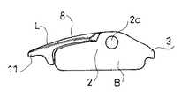
以下、図1〜図21に基づいて、この発明の典型的な実施の形態について、説明する。この実施の形態にかかるバックルは、典型的には、このバックルを介して帯状体の端部側を、その帯状体の他方の端部側や、別の帯状体や、物品本体などの被接続体に対し、留め付け位置の調整可能な状態で、接続させるために用いられるものである。 Hereinafter, typical embodiments of the present invention will be described with reference to FIGS. The buckle according to this embodiment is typically connected to the end side of the band-like body through the buckle, the other end side of the band-like body, another band-like body, the article body, and the like. It is used to connect to the body with the fastening position adjustable.
かかるバックルは、ベースBと、レバー体Lとから構成されている。レバー体LはベースBに起伏動可能に組み合わされると共に所定の起立位置においてこのベースBとの間に通した前記帯状体Wを所定の伏倒状態においてこのベースBとの間で挟持するように構成されている。 Such a buckle includes a base B and a lever body L. The lever body L is combined with the base B so as to be able to move up and down, and the belt-like body W passed between the base body B and the base body B in a predetermined standing position is clamped between the base body B and the base body B in a predetermined lying state. It is configured.
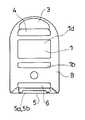
ベースBには、被接続体の取り付け部1eが備えられている。例えば、このベースBの取り付け部1eをもって、このベースBを他の帯状体Wに取り付けさせるようにすれば、バックルを介して二つの帯状体W、つまり、前記レバー体Lとの間で挟持される帯状体Wとこの他の帯状体Wとを接続できるようになる。また、このベースBの取り付け部1eをもって、このベースBを一つの帯状体Wの一方の端部側に取り付けさせるようにすれば、バックルを介してこの一つの帯状体Wの両端部を接続させ合わせ可能となる。(図4)また、図示は省略するが、このベースBの取り付け部1eをもって、このベースBをかばん本体などに取り付けさせるようにすれば、バックルを介してこのかばん本体などに帯状体Wを接続できるようになる。 The base B is provided with an
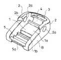
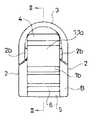
かかるベースBは、基部1と、この基部1から突出するレバー体Lの支持部2とを備えている。図示の例では、基部1は、対向辺部にそれぞれ支持部2を備えた板状をなすように構成されている。 The base B includes a
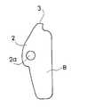
支持部2は、この基部1の表面1aに直交する向きに突き出す側板状をなすように構成されている。支持部2の両端部はそれぞれ、この支持部2の設けられていない基部1の辺部よりも前方に位置されている。一対の支持部2、2の一方の端部間には、この側にある基部1の辺部との間に帯状体Wの第一通しスロット4を形成させるようにして、第一クロスバー3が架設されている。第一クロスバー3は、基部1より上方に位置され、また、基部1の前記辺部の側を湾曲内側とするようにその外縁側を弧状に湾曲させている。また、一対の支持部2、2の他方の端部間には、この側にある基部1の辺部との間に帯状体Wの第二通しスロット6を形成させるようにして、第二クロスバー5が架設されている。第二クロスバー5も、基部1より上方に位置されている。 The
基部1の中央には、前記第一及び第二通しスロット4、6に平行をなす第三通しスロット1bが一対の支持部2、2間に亘るように設けられている。また、基部1の表面1aにおける第一通しスロット4に臨んだ縁部には、一対の支持部2、2間に亘るリブ1cが形成されている。 In the center of the
図示の例では、基部1の裏面1d側から第二通しスロット6を通じて基部1の表面1a側に引き出した帯状体Wを第三通しスロット1bを通じて再び基部1の裏面1d側に引き出すように両通しスロット6、1bに通すことで、かかる帯状体Wを両通しスロット6、1b間にある基部1の一部にかけ回すようにしてベースBにかかる帯状体Wを取り付けることができるようになっている。すなわち、図示の例では、かかる第二通しスロット6と第三通しスロット1bにより前記取り付け部1eを構成させている。 In the illustrated example, the belt-like body W pulled out from the
また、支持部2における第一通しスロット4と第三通しスロット1bの間に位置される箇所に、この支持部2を内外に貫通する軸穴2aが形成されている。 Further, a
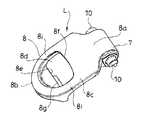
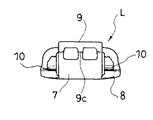
レバー体Lは、かかるベースBに起伏動可能に組み合わされるようになっている。このレバー体Lは、ベースBへの組み合わせ部7から延び出す操作部8と、この操作部8の延び出し方向と異なる向きにこの組み合わせ部7から突き出す挟持部9とを備えている。レバー体Lの所定の伏倒位置において、この挟持部9とベースBの基部1との間で帯状体Wの前記挟持がなされるようになっている。 The lever body L is combined with the base B so as to be movable up and down. The lever body L includes an
図示の例では、操作部8は、組み合わせ部7の側をベースBの一対の支持部2、2間に納まる幅狭部8aとすると共に、この幅狭部8aから末端8bまでの間をベースBの一対の支持部2、2の外面間の間隔と略等しい幅を備えた幅広部8cとしている。 In the example shown in the figure, the
挟持部9は、組み合わせ部7から、操作部8の延びだし方向に対し略直交する向きに突き出している。図示の例では、挟持部9の突き出し端9aは、レバー体Lの操作部8の幅広部8cがベースBの支持部2に突き当たったレバー体Lの所定の伏倒位置において、前記リブ1cよりも第三通しスロット1b側に位置してベースBの基部1の表面1aとの間に帯状体Wの厚さよりもやや小さい隙間を作って向き合うようになっている。(図4)この挟持部9の突き出し端9aは、操作部8の幅狭部8aの全幅に亘るリブ状をなすように構成されている。挟持部9における操作部8の末端8b側に向けられた一方側部9bは、この末端8bに向かうに連れて挟持部9の突きだし寸法を小さくする傾斜状をなすように構成されている。一方、挟持部9の他方側部9cは、前記起伏動の回動中心を円心とした仮想の円の円弧に沿った弧状をなすように構成されている。レバー体Lは、前記所定の伏倒位置と、この挟持部9の他方側部9cをベースBの基部1の表面1aに向けた所定の起立位置との間に亘る起伏動可能にベースBに組み合わされている。かかる所定の起立位置において、レバー体Lの挟持部9の他方側部9cとベースBの基部1の表面1aとの間には、帯状体Wの厚さと略等しいかこれより広い隙間が形成されるようになっている。(図5) The
図示の例では、前記操作部8の延び出し基部であり、挟持部9の突きだし基部でもある組み合わせ部7において、レバー体Lの両側部にそれぞれ軸突起10が形成されており、レバー体LはベースBの一対の支持部2、2の一方の軸穴2aにこの軸突起10の一方を入れ込ませ、かつ、ベースBの一対の支持部2、2の他方の軸穴2aにこの軸突起10の他方を入れ込ませることにより、この軸突起10を回動中心とした回動可能にベースBに組み合わされている。図示の例では、ベースBの支持部2の突き出し端と軸穴2aとの間に案内溝2bが形成されていると共に、レバー体Lの軸突起10における挟持部9の突き出し側に向けられた端部に傾斜面10aが形成されており、この案内溝2bと傾斜面10aとを利用してベースBの一対の支持部2、2の間の間隔を弾性的に押し広げながら軸穴2aに軸突起10が入り込む位置までこの一対の支持部2、2の間にレバー体Lを押し込んでレバー体LとベースBとの前記組み合わせをなすようになっている。レバー体Lの軸突起10と挟持部9の突き出し端9aとの間の寸法は、ベースBの支持部2に形成された軸穴2aの直下でのこの軸穴2aと基部1の表面1aとの間の寸法よりもやや小さくなるようにしてある。 In the illustrated example, in the
また、レバー体Lの操作部8には、前記帯状体Wの通し部8dと、前記伏倒位置においてベースBに設けた被掛合部5aに掛合される掛合部8gとが備えられている。 Further, the operating
通し部8dは、操作部8の幅広部8cを内外に貫通した窓穴状を呈している。この通し部8dにおける操作部8の延びだし方向に直交する向きの幅は、前記帯状体Wの幅と略等しいか、これよりやや大きくなるようにしてある。この通し部8dにおける操作部8の延びだし方向に直交する向きに沿った二箇所の穴縁部の8e、8fうち、操作部8の末端8b側に位置される穴縁部8eは、レバー体Lの前記所定の伏倒位置において、前記第二クロスバー5の直上に位置されるようになっている。 The through
また、通し部8dにおける操作部8の延びだし方向に直交する向きに沿った二箇所の穴縁部8e、8fのうち、前記組み合わせ部7、すなわち、操作部8の延び出し基部1側に位置される穴縁部8fは、この組み合わせ部7側を湾曲外側とするように湾曲されている。 Of the two
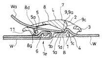
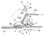
レバー体Lを前記所定の起立位置に位置づけた状態から挟持部9の前記他方側面9cとベースBの基部1との間に帯状体Wを通し、さらに、この帯状体Wを操作部8の通し部8dに通して引き出す。この状態からレバー体Lを操作部8を利用して前記所定の伏倒位置に回動させることで挟持部9とベースBの基部1との間でこの帯状体Wを挟持してこの帯状体Wの長さ方向の任意の位置にバックルは留め付けられる。(図4)帯状体Wはレバー体Lの操作部8の通し部8dに通されて引き出されていることから、この帯状体Wの引き出し端Waを摘むなどしてこの引き出し端Waを持ち上げることでレバー体Lを所定の起立位置に回動させて帯状体Wに対するバックルの前記留め付けを解くことができる。このように帯状体Wの引き出し端Waを持ち上げ操作した場合、張力の作用される帯状体Wは前記のように湾曲された通し部8dの穴縁部に両端側の二箇所で圧接することから帯状体Wはスリップし難く、この持ち上げ操作の力をロスなくレバー体Lに伝達できるようになっている。 From the state in which the lever body L is positioned at the predetermined standing position, the belt-like body W is passed between the
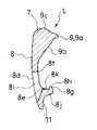
掛合部8gは、レバー体Lの操作部8の末端8b側に設けられている。従って、ベースBの被掛合部5aは、伏倒位置にあるレバー体Lの操作部8の末端8bの下側となる箇所に設けられている。これにより、レバー体Lが所定の伏倒位置にあってベースBとの間で帯状体Wを挟持してこれに留め付いた状態を一層強固に維持できるようになっている。特に、掛合部8gはレバー体Lの回動中心から離れた操作部8の末端8b側にあることから、掛合部8gをかかる回動中心に近い位置に設けた場合に比べて比較的大きな力をこの末端8b作用させなければこの掛合部8gの掛合状態を解くことができないようになっている。 The engaging
より具体的には、この実施の形態にあっては、掛合部8gは、レバー体Lの組み合わせ部7側に突き出す爪状をなすように構成されている。これにより、レバー体Lが前記所定の伏倒位置にある状態から通し部8dに通された帯状体Wが前記持ち上げ操作された場合には、掛合部8gには被掛合部5aにより引っかかる方向の力が作用され、単純にこのような持ち上げ操作がなされただけでは掛合部8gの掛合は解かれ難くなっている。また、レバー体Lの通し部8dにおけるレバー体Lの操作部8の末端8b側に位置される穴縁部にこの掛合部8gは備えられている。これにより、この実施の形態にあっては、かかる掛合部8gをバックルの構造を複雑にすることなく、したがって、成形し易い態様で、レバー体Lに備えさせることができるようになっている。また、レバー体Lの通し部8dは、この通し部8dとレバー体Lの操作部雄8の側部との間を弾性変形可能部とする大きさを持つようにしてある。これにより、この実施の形態にあっては、掛合部8gの掛合の解除にあたっては、レバー体Lの操作部8の末端8b側にベースBから離れる向きの力を作用させることにより、かかる通し部8dとレバー体Lの側部との間にある箇所8iを掛合部8gが被掛合部5aから外れる向きにスムースに弾性変形できるようになっている。 More specifically, in this embodiment, the engaging
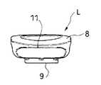
図示の例では、レバー体Lの操作部8には、通し部8dにおける操作部8の延びだし方向に直交する向きに沿った二箇所の穴縁部8e、8fのうち操作部8の末端8b側に位置される穴縁部8eに壁一面を連続させるようにして、この操作部8の裏面からこの裏面に略直交する向きに突き出す壁部8jが、操作部8の全幅に亘って形成されている。この壁部8jと操作部8の末端8bとの間には間隔が形成されており、この間が前記掛合解除時の指かけ部11として機能するようになっている。掛合部8gはこの壁部8jの壁一面8kの下端から組み合わせ部7の側に突き出す爪状をなす。掛合部8gは操作部8の幅方向中程の位置において一定の範囲で前記壁部8jに形成されている。 In the example shown in the drawing, the
ベースBの被掛合部5aは、前記第二クロスバー5に形成されている。図示の例では、この被掛合部5aは、第二クロスバー5における第二通しスロット6に臨んだ側と反対の外側面部に形成されている。図示の例では、この外側面部に第二クロスバー5の上面部との間に間隔を開けて凹所5bを形成させており、この凹所5bにおけるこの上面部側に位置される段差が前記被掛合部5aとして機能するようになっている。すなわち、レバー体Lの回動中心から掛合部8gの爪先までの距離は、この回動中心から第二クロスバー5の外側面部までの距離よりやや小さくなるようにしてある。図示の例では、掛合部8gは、その下側面8hを爪先に向かうに連れて掛合部8gの上下方向の肉厚を小さくするように傾斜させており、レバー体Lを所定の伏倒位置に向けて回動させる過程でこの掛合部8gの下側面8hを第二クロスバー5の外側面部に当接させることで、レバー体Lの末端8b側をやや弾性変形させてこの掛合部8gが被掛合部5a下に入り込みこれと掛合する前記所定の伏倒位置までレバー体Lをスムースに回動操作できるようになっている。 The hooked
掛合部8gの掛合の解除は、前記指かけ部11にベースBから離れる向きの力を作用させて前記通し部8dとレバー体Lの側部との間にある箇所8iを弾性変形させることでなされる。この解除に前記壁部8jの弾性変形は必要とされないことから、この壁部8jのレバー体Lの操作部8からの突きだし寸法は必要最小限に設定されている。 The engagement of the
以上に説明したバックルにおける弾性変形特性を有すべき箇所へのこの特性の付与は、かかるバックルを合成樹脂の成形品とすることで、容易に実現することができる。 The imparting of this characteristic to the portion that should have the elastic deformation characteristic in the buckle as described above can be easily realized by using the buckle as a synthetic resin molded product.
W 帯状体
B ベース
L レバー体
1e 取り付け部
5a 被掛合部
7 組み合わせ部
8 操作部
8d 通し部
8g 掛合部
9 挟持部W belt-like body B base
Claims (5)
Translated fromJapaneseレバー体は、ベースへの組み合わせ部から延び出す操作部と、この操作部の延び出し方向と異なる方向にこの組み合わせ部から突き出して前記挟持をなす挟持部とを備えていると共に、
操作部には、前記帯状体の通し部と、前記伏倒位置においてベースの外側に設けた被掛合部に掛合される掛合部とが備えられており、
しかも、前記掛合部は、レバー体の操作部の末端側に設けられていると共に、レバー体の組み合わせ部側に突き出す爪状をなすことを特徴とするバックル。A buckle for connecting a belt-like body to a connected body, the base having an attachment portion of the connected body, and a base that is movably combined with the base and passed between the base at a predetermined standing position. And a lever body for sandwiching the belt-like body with the base in a predetermined lying state,
The lever body includes an operation portion that extends from the combination portion to the base, and a clamping portion that protrudes from the combination portion in a direction different from the extending direction of the operation portion and performs the clamping.
The operation portion includes a through portion of the belt-like body, and a hooking portion that is hooked to a hooked portion provided onthe outside of the base atthe lying position,
And the said engaging part is provided in the terminal side of the operation part of a lever body, and makes the nail | claw shape which protrudes in the combination part side of a lever body, The buckle characterized by the above-mentioned.
Priority Applications (2)
| Application Number | Priority Date | Filing Date | Title |
|---|---|---|---|
| JP2010174331AJP5628585B2 (en) | 2010-08-03 | 2010-08-03 | buckle |
| CN201110225167.4ACN102342630B (en) | 2010-08-03 | 2011-08-03 | Buckle |
Applications Claiming Priority (1)
| Application Number | Priority Date | Filing Date | Title |
|---|---|---|---|
| JP2010174331AJP5628585B2 (en) | 2010-08-03 | 2010-08-03 | buckle |
Publications (2)
| Publication Number | Publication Date |
|---|---|
| JP2012030011A JP2012030011A (en) | 2012-02-16 |
| JP5628585B2true JP5628585B2 (en) | 2014-11-19 |
Family
ID=45542003
Family Applications (1)
| Application Number | Title | Priority Date | Filing Date |
|---|---|---|---|
| JP2010174331AActiveJP5628585B2 (en) | 2010-08-03 | 2010-08-03 | buckle |
Country Status (2)
| Country | Link |
|---|---|
| JP (1) | JP5628585B2 (en) |
| CN (1) | CN102342630B (en) |
Families Citing this family (4)
| Publication number | Priority date | Publication date | Assignee | Title |
|---|---|---|---|---|
| JP5734892B2 (en)* | 2012-02-16 | 2015-06-17 | イワブチ株式会社 | Band fastener |
| CN103815620A (en)* | 2014-03-15 | 2014-05-28 | 李建明 | Jointing block of belt fastener |
| EP3283020B1 (en)* | 2015-04-17 | 2020-06-03 | Vision Quest Industries Incorporated Dba VQ Orthocare | Orthotic device with snap fit cuff and latch mechanism |
| CN109386573B (en)* | 2017-08-10 | 2020-12-29 | 岩渊株式会社 | with fasteners |
Family Cites Families (8)
| Publication number | Priority date | Publication date | Assignee | Title |
|---|---|---|---|---|
| JPS54102326U (en)* | 1977-12-26 | 1979-07-19 | ||
| JPH0619521U (en)* | 1992-08-24 | 1994-03-15 | 株式会社ニフコ | buckle |
| US5469583A (en)* | 1993-09-16 | 1995-11-28 | Bell Sports, Inc. | Strap lock buckle |
| US5572771A (en)* | 1994-11-22 | 1996-11-12 | Kelleghan; Brian J. | Strap buckle |
| JP3880657B2 (en)* | 1996-06-24 | 2007-02-14 | 内田鍛工株式会社 | Band fastener |
| CN100536709C (en)* | 2006-04-04 | 2009-09-09 | 株式会社利富高 | buckle |
| JP4951315B2 (en)* | 2006-04-04 | 2012-06-13 | 株式会社ニフコ | buckle |
| JP4319198B2 (en)* | 2006-04-28 | 2009-08-26 | 東光化学工業株式会社 | Band fastener |
- 2010
- 2010-08-03JPJP2010174331Apatent/JP5628585B2/enactiveActive
- 2011
- 2011-08-03CNCN201110225167.4Apatent/CN102342630B/ennot_activeExpired - Fee Related
Also Published As
| Publication number | Publication date |
|---|---|
| JP2012030011A (en) | 2012-02-16 |
| CN102342630B (en) | 2015-07-01 |
| CN102342630A (en) | 2012-02-08 |
Similar Documents
| Publication | Publication Date | Title |
|---|---|---|
| CN103153113B (en) | Cam lock buckle | |
| US9113680B2 (en) | Buckle | |
| JP2802918B2 (en) | Plastic buckle | |
| CN205125270U (en) | Buckle tool | |
| TWI528912B (en) | Buckle | |
| TWI418311B (en) | Buckle | |
| JPS6255401B2 (en) | ||
| CN113163904B (en) | Plug for buckle and buckle | |
| JP5628585B2 (en) | buckle | |
| US10588383B2 (en) | Buckle | |
| ITTO990835A1 (en) | BUCKLE. | |
| CN109152454A (en) | Sling | |
| CN110482004B (en) | Rope belt fastener | |
| JPH08173218A (en) | Cord stopper | |
| TWI655377B (en) | Rope lock | |
| JP3426558B2 (en) | EquipmentPortable belt terminal equipment | |
| JP2009018003A (en) | String lock | |
| JP4149038B2 (en) | buckle | |
| JP2009056302A (en) | buckle | |
| CN203492913U (en) | Rope buckle | |
| JP4473984B2 (en) | String terminal cover | |
| CN216019477U (en) | Cord tail buckle that can adjust the length of the rope at the same time | |
| CN212465041U (en) | Fixtures and masks | |
| CN112401413B (en) | Belt buckle with wire adjusting part | |
| CN115251540A (en) | Eye-splice |
Legal Events
| Date | Code | Title | Description |
|---|---|---|---|
| A621 | Written request for application examination | Free format text:JAPANESE INTERMEDIATE CODE: A621 Effective date:20130521 | |
| A977 | Report on retrieval | Free format text:JAPANESE INTERMEDIATE CODE: A971007 Effective date:20140214 | |
| A131 | Notification of reasons for refusal | Free format text:JAPANESE INTERMEDIATE CODE: A131 Effective date:20140304 | |
| A521 | Request for written amendment filed | Free format text:JAPANESE INTERMEDIATE CODE: A523 Effective date:20140423 | |
| TRDD | Decision of grant or rejection written | ||
| A01 | Written decision to grant a patent or to grant a registration (utility model) | Free format text:JAPANESE INTERMEDIATE CODE: A01 Effective date:20140916 | |
| A61 | First payment of annual fees (during grant procedure) | Free format text:JAPANESE INTERMEDIATE CODE: A61 Effective date:20141002 | |
| R150 | Certificate of patent or registration of utility model | Ref document number:5628585 Country of ref document:JP Free format text:JAPANESE INTERMEDIATE CODE: R150 | |
| R250 | Receipt of annual fees | Free format text:JAPANESE INTERMEDIATE CODE: R250 | |
| R250 | Receipt of annual fees | Free format text:JAPANESE INTERMEDIATE CODE: R250 | |
| R250 | Receipt of annual fees | Free format text:JAPANESE INTERMEDIATE CODE: R250 | |
| R250 | Receipt of annual fees | Free format text:JAPANESE INTERMEDIATE CODE: R250 | |
| R250 | Receipt of annual fees | Free format text:JAPANESE INTERMEDIATE CODE: R250 | |
| R250 | Receipt of annual fees | Free format text:JAPANESE INTERMEDIATE CODE: R250 | |
| R250 | Receipt of annual fees | Free format text:JAPANESE INTERMEDIATE CODE: R250 | |
| R250 | Receipt of annual fees | Free format text:JAPANESE INTERMEDIATE CODE: R250 | |
| R250 | Receipt of annual fees | Free format text:JAPANESE INTERMEDIATE CODE: R250 |