JP5622743B2 - Injection device having holding means for preventing unintentional movement of the piston rod - Google Patents
Injection device having holding means for preventing unintentional movement of the piston rodDownload PDFInfo
- Publication number
- JP5622743B2 JP5622743B2JP2011538986AJP2011538986AJP5622743B2JP 5622743 B2JP5622743 B2JP 5622743B2JP 2011538986 AJP2011538986 AJP 2011538986AJP 2011538986 AJP2011538986 AJP 2011538986AJP 5622743 B2JP5622743 B2JP 5622743B2
- Authority
- JP
- Japan
- Prior art keywords
- piston rod
- housing
- injection
- injection device
- holding means
- Prior art date
- Legal status (The legal status is an assumption and is not a legal conclusion. Google has not performed a legal analysis and makes no representation as to the accuracy of the status listed.)
- Active
Links
- 238000002347injectionMethods0.000titleclaimsdescription85
- 239000007924injectionSubstances0.000titleclaimsdescription85
- 230000007246mechanismEffects0.000claimsdescription24
- 238000006073displacement reactionMethods0.000claimsdescription8
- 239000000243solutionSubstances0.000claimsdescription8
- 230000003068static effectEffects0.000claimsdescription8
- 230000005540biological transmissionEffects0.000claimsdescription6
- 230000001939inductive effectEffects0.000claimsdescription4
- 239000002184metalSubstances0.000claimsdescription4
- 230000008878couplingEffects0.000claimsdescription2
- 238000010168coupling processMethods0.000claimsdescription2
- 238000005859coupling reactionMethods0.000claimsdescription2
- 230000006698inductionEffects0.000claims2
- 239000004033plasticSubstances0.000description6
- 229920003023plasticPolymers0.000description6
- 230000009471actionEffects0.000description4
- 238000004519manufacturing processMethods0.000description4
- -1polyethylenePolymers0.000description4
- 229910000639Spring steelInorganic materials0.000description3
- 239000003814drugSubstances0.000description3
- 229940079593drugDrugs0.000description3
- 230000005489elastic deformationEffects0.000description3
- 230000008901benefitEffects0.000description2
- 230000015572biosynthetic processEffects0.000description2
- 230000036961partial effectEffects0.000description2
- 230000002829reductive effectEffects0.000description2
- 229930040373ParaformaldehydeNatural products0.000description1
- 239000004952PolyamideSubstances0.000description1
- 239000004698PolyethyleneSubstances0.000description1
- 239000004743PolypropyleneSubstances0.000description1
- 230000006978adaptationEffects0.000description1
- 238000005452bendingMethods0.000description1
- 230000006835compressionEffects0.000description1
- 238000007906compressionMethods0.000description1
- 238000010586diagramMethods0.000description1
- 230000000694effectsEffects0.000description1
- 238000003912environmental pollutionMethods0.000description1
- 239000012530fluidSubstances0.000description1
- 238000009499grossingMethods0.000description1
- 230000006872improvementEffects0.000description1
- 229940102223injectable solutionDrugs0.000description1
- 230000000670limiting effectEffects0.000description1
- 239000000463materialSubstances0.000description1
- 239000000203mixtureSubstances0.000description1
- 229920002647polyamidePolymers0.000description1
- 229920000573polyethylenePolymers0.000description1
- 229920006324polyoxymethylenePolymers0.000description1
- 229920001155polypropylenePolymers0.000description1
- 229920001343polytetrafluoroethylenePolymers0.000description1
- 239000004810polytetrafluoroethyleneSubstances0.000description1
- 229920002635polyurethanePolymers0.000description1
- 239000004814polyurethaneSubstances0.000description1
- 230000000717retained effectEffects0.000description1
Images


Classifications
- A—HUMAN NECESSITIES
- A61—MEDICAL OR VETERINARY SCIENCE; HYGIENE
- A61M—DEVICES FOR INTRODUCING MEDIA INTO, OR ONTO, THE BODY; DEVICES FOR TRANSDUCING BODY MEDIA OR FOR TAKING MEDIA FROM THE BODY; DEVICES FOR PRODUCING OR ENDING SLEEP OR STUPOR
- A61M5/00—Devices for bringing media into the body in a subcutaneous, intra-vascular or intramuscular way; Accessories therefor, e.g. filling or cleaning devices, arm-rests
- A61M5/178—Syringes
- A61M5/31—Details
- A61M5/315—Pistons; Piston-rods; Guiding, blocking or restricting the movement of the rod or piston; Appliances on the rod for facilitating dosing ; Dosing mechanisms
- A61M5/31533—Dosing mechanisms, i.e. setting a dose
- A61M5/31545—Setting modes for dosing
- A61M5/31548—Mechanically operated dose setting member
- A61M5/3155—Mechanically operated dose setting member by rotational movement of dose setting member, e.g. during setting or filling of a syringe
- A61M5/31551—Mechanically operated dose setting member by rotational movement of dose setting member, e.g. during setting or filling of a syringe including axial movement of dose setting member
- A—HUMAN NECESSITIES
- A61—MEDICAL OR VETERINARY SCIENCE; HYGIENE
- A61M—DEVICES FOR INTRODUCING MEDIA INTO, OR ONTO, THE BODY; DEVICES FOR TRANSDUCING BODY MEDIA OR FOR TAKING MEDIA FROM THE BODY; DEVICES FOR PRODUCING OR ENDING SLEEP OR STUPOR
- A61M5/00—Devices for bringing media into the body in a subcutaneous, intra-vascular or intramuscular way; Accessories therefor, e.g. filling or cleaning devices, arm-rests
- A61M5/178—Syringes
- A61M5/31—Details
- A61M5/315—Pistons; Piston-rods; Guiding, blocking or restricting the movement of the rod or piston; Appliances on the rod for facilitating dosing ; Dosing mechanisms
- A61M5/31501—Means for blocking or restricting the movement of the rod or piston
- A61M5/31505—Integral with the syringe barrel, i.e. connected to the barrel so as to make up a single complete piece or unit
- A—HUMAN NECESSITIES
- A61—MEDICAL OR VETERINARY SCIENCE; HYGIENE
- A61M—DEVICES FOR INTRODUCING MEDIA INTO, OR ONTO, THE BODY; DEVICES FOR TRANSDUCING BODY MEDIA OR FOR TAKING MEDIA FROM THE BODY; DEVICES FOR PRODUCING OR ENDING SLEEP OR STUPOR
- A61M5/00—Devices for bringing media into the body in a subcutaneous, intra-vascular or intramuscular way; Accessories therefor, e.g. filling or cleaning devices, arm-rests
- A61M5/178—Syringes
- A61M5/31—Details
- A61M5/315—Pistons; Piston-rods; Guiding, blocking or restricting the movement of the rod or piston; Appliances on the rod for facilitating dosing ; Dosing mechanisms
- A61M5/31533—Dosing mechanisms, i.e. setting a dose
- A61M5/31535—Means improving security or handling thereof, e.g. blocking means, means preventing insufficient dosing, means allowing correction of overset dose
- A61M5/31536—Blocking means to immobilize a selected dose, e.g. to administer equal doses
- A—HUMAN NECESSITIES
- A61—MEDICAL OR VETERINARY SCIENCE; HYGIENE
- A61M—DEVICES FOR INTRODUCING MEDIA INTO, OR ONTO, THE BODY; DEVICES FOR TRANSDUCING BODY MEDIA OR FOR TAKING MEDIA FROM THE BODY; DEVICES FOR PRODUCING OR ENDING SLEEP OR STUPOR
- A61M5/00—Devices for bringing media into the body in a subcutaneous, intra-vascular or intramuscular way; Accessories therefor, e.g. filling or cleaning devices, arm-rests
- A61M5/178—Syringes
- A61M5/24—Ampoule syringes, i.e. syringes with needle for use in combination with replaceable ampoules or carpules, e.g. automatic
- A61M2005/2403—Ampoule inserted into the ampoule holder
- A61M2005/2407—Ampoule inserted into the ampoule holder from the rear
- A—HUMAN NECESSITIES
- A61—MEDICAL OR VETERINARY SCIENCE; HYGIENE
- A61M—DEVICES FOR INTRODUCING MEDIA INTO, OR ONTO, THE BODY; DEVICES FOR TRANSDUCING BODY MEDIA OR FOR TAKING MEDIA FROM THE BODY; DEVICES FOR PRODUCING OR ENDING SLEEP OR STUPOR
- A61M5/00—Devices for bringing media into the body in a subcutaneous, intra-vascular or intramuscular way; Accessories therefor, e.g. filling or cleaning devices, arm-rests
- A61M5/178—Syringes
- A61M5/24—Ampoule syringes, i.e. syringes with needle for use in combination with replaceable ampoules or carpules, e.g. automatic
- A61M2005/2485—Ampoule holder connected to rest of syringe
- A61M2005/2488—Ampoule holder connected to rest of syringe via rotation, e.g. threads or bayonet
- A—HUMAN NECESSITIES
- A61—MEDICAL OR VETERINARY SCIENCE; HYGIENE
- A61M—DEVICES FOR INTRODUCING MEDIA INTO, OR ONTO, THE BODY; DEVICES FOR TRANSDUCING BODY MEDIA OR FOR TAKING MEDIA FROM THE BODY; DEVICES FOR PRODUCING OR ENDING SLEEP OR STUPOR
- A61M5/00—Devices for bringing media into the body in a subcutaneous, intra-vascular or intramuscular way; Accessories therefor, e.g. filling or cleaning devices, arm-rests
- A61M5/178—Syringes
- A61M5/31—Details
- A61M5/315—Pistons; Piston-rods; Guiding, blocking or restricting the movement of the rod or piston; Appliances on the rod for facilitating dosing ; Dosing mechanisms
- A61M5/31501—Means for blocking or restricting the movement of the rod or piston
- A61M2005/3151—Means for blocking or restricting the movement of the rod or piston by friction
- A—HUMAN NECESSITIES
- A61—MEDICAL OR VETERINARY SCIENCE; HYGIENE
- A61M—DEVICES FOR INTRODUCING MEDIA INTO, OR ONTO, THE BODY; DEVICES FOR TRANSDUCING BODY MEDIA OR FOR TAKING MEDIA FROM THE BODY; DEVICES FOR PRODUCING OR ENDING SLEEP OR STUPOR
- A61M5/00—Devices for bringing media into the body in a subcutaneous, intra-vascular or intramuscular way; Accessories therefor, e.g. filling or cleaning devices, arm-rests
- A61M5/178—Syringes
- A61M5/31—Details
- A61M5/315—Pistons; Piston-rods; Guiding, blocking or restricting the movement of the rod or piston; Appliances on the rod for facilitating dosing ; Dosing mechanisms
- A61M5/31511—Piston or piston-rod constructions, e.g. connection of piston with piston-rod
- A61M2005/3152—Piston or piston-rod constructions, e.g. connection of piston with piston-rod including gearings to multiply or attenuate the piston displacing force
- A—HUMAN NECESSITIES
- A61—MEDICAL OR VETERINARY SCIENCE; HYGIENE
- A61M—DEVICES FOR INTRODUCING MEDIA INTO, OR ONTO, THE BODY; DEVICES FOR TRANSDUCING BODY MEDIA OR FOR TAKING MEDIA FROM THE BODY; DEVICES FOR PRODUCING OR ENDING SLEEP OR STUPOR
- A61M2205/00—General characteristics of the apparatus
- A61M2205/58—Means for facilitating use, e.g. by people with impaired vision
- A61M2205/583—Means for facilitating use, e.g. by people with impaired vision by visual feedback
- A—HUMAN NECESSITIES
- A61—MEDICAL OR VETERINARY SCIENCE; HYGIENE
- A61M—DEVICES FOR INTRODUCING MEDIA INTO, OR ONTO, THE BODY; DEVICES FOR TRANSDUCING BODY MEDIA OR FOR TAKING MEDIA FROM THE BODY; DEVICES FOR PRODUCING OR ENDING SLEEP OR STUPOR
- A61M5/00—Devices for bringing media into the body in a subcutaneous, intra-vascular or intramuscular way; Accessories therefor, e.g. filling or cleaning devices, arm-rests
- A61M5/178—Syringes
- A61M5/24—Ampoule syringes, i.e. syringes with needle for use in combination with replaceable ampoules or carpules, e.g. automatic
- A—HUMAN NECESSITIES
- A61—MEDICAL OR VETERINARY SCIENCE; HYGIENE
- A61M—DEVICES FOR INTRODUCING MEDIA INTO, OR ONTO, THE BODY; DEVICES FOR TRANSDUCING BODY MEDIA OR FOR TAKING MEDIA FROM THE BODY; DEVICES FOR PRODUCING OR ENDING SLEEP OR STUPOR
- A61M5/00—Devices for bringing media into the body in a subcutaneous, intra-vascular or intramuscular way; Accessories therefor, e.g. filling or cleaning devices, arm-rests
- A61M5/178—Syringes
- A61M5/31—Details
- A61M5/315—Pistons; Piston-rods; Guiding, blocking or restricting the movement of the rod or piston; Appliances on the rod for facilitating dosing ; Dosing mechanisms
- A61M5/31533—Dosing mechanisms, i.e. setting a dose
- A61M5/31545—Setting modes for dosing
- A61M5/31548—Mechanically operated dose setting member
- A61M5/31556—Accuracy improving means
- A61M5/31558—Accuracy improving means using scaling up or down transmissions, e.g. gearbox
- A—HUMAN NECESSITIES
- A61—MEDICAL OR VETERINARY SCIENCE; HYGIENE
- A61M—DEVICES FOR INTRODUCING MEDIA INTO, OR ONTO, THE BODY; DEVICES FOR TRANSDUCING BODY MEDIA OR FOR TAKING MEDIA FROM THE BODY; DEVICES FOR PRODUCING OR ENDING SLEEP OR STUPOR
- A61M5/00—Devices for bringing media into the body in a subcutaneous, intra-vascular or intramuscular way; Accessories therefor, e.g. filling or cleaning devices, arm-rests
- A61M5/178—Syringes
- A61M5/31—Details
- A61M5/315—Pistons; Piston-rods; Guiding, blocking or restricting the movement of the rod or piston; Appliances on the rod for facilitating dosing ; Dosing mechanisms
- A61M5/31565—Administration mechanisms, i.e. constructional features, modes of administering a dose
- A61M5/31576—Constructional features or modes of drive mechanisms for piston rods
- A61M5/31583—Constructional features or modes of drive mechanisms for piston rods based on rotational translation, i.e. movement of piston rod is caused by relative rotation between the user activated actuator and the piston rod
- A61M5/31585—Constructional features or modes of drive mechanisms for piston rods based on rotational translation, i.e. movement of piston rod is caused by relative rotation between the user activated actuator and the piston rod performed by axially moving actuator, e.g. an injection button
Landscapes
- Health & Medical Sciences (AREA)
- Vascular Medicine (AREA)
- Engineering & Computer Science (AREA)
- Anesthesiology (AREA)
- Biomedical Technology (AREA)
- Heart & Thoracic Surgery (AREA)
- Hematology (AREA)
- Life Sciences & Earth Sciences (AREA)
- Animal Behavior & Ethology (AREA)
- General Health & Medical Sciences (AREA)
- Public Health (AREA)
- Veterinary Medicine (AREA)
- Infusion, Injection, And Reservoir Apparatuses (AREA)
Description
Translated fromJapanese本発明は、その近位ハウジング部分において、注射液を有する容器を受けるために、そしてその遠位ハウジング部分において、用量設定・注射機構を受けるために適合されているハウジングを含む注射デバイスであって、ここで、本機構が、容器から注射液を投薬するために、ハウジングに対して軸方向に移動され得るピストンロッド、ここでピストンロッドが外ねじ山を有し、そしてハウジングに対してトルクに耐えるような形で配置され、ねじ山付きエレメントを含む用量設定手段を含み、そのねじを切られたエレメントが、ピストンロッドの外ねじ山に係合されている内ねじ山を有し、ハウジングに対するその軸位置が変えられるように設計され、そして注射用量の設定中に、ピストンロッドに対して及びハウジングに対して回転でき、ここで、用量設定手段が、ねじ山付きエレメント及びピストンロッドがハウジングに対して軸方向に一緒に変位可能となる形で、事前設定注射用量の注射に、ねじ山付きエレメントがピストンロッド及びハウジングに対してトルクに耐えるような形で保持されるように設計され、ここで、本機構が更に、ピストンロッドと接触している、そして注射用量の投薬を除く装置の使用中に、ピストンロッドの軸方向変位が固定化できる又は実質的に固定化できるように設計される保持手段を含む注射デバイスに関する。 The present invention is an injection device comprising a housing adapted to receive a container having an injection solution in its proximal housing portion and in its distal housing portion to receive a dose setting and injection mechanism. Where the mechanism can be moved axially relative to the housing in order to dispense the injection solution from the container, wherein the piston rod has an external thread and is torqued relative to the housing Comprising a dose setting means arranged to withstand and including a threaded element, the threaded element having an inner thread engaged with the outer thread of the piston rod, to the housing Its axial position is designed to be variable and can rotate relative to the piston rod and relative to the housing during injection dose setting Here, the dose setting means is adapted for the injection of the preset injection dose, the threaded element on the piston rod and the housing in such a way that the threaded element and the piston rod are axially displaceable together with respect to the housing. Designed to be held in a manner that resists torque, wherein the mechanism is further in contact with the piston rod, and the piston rod shaft is in use during use of the device excluding injection dose dispensing. The invention relates to an injection device comprising holding means designed so that the directional displacement can be fixed or substantially fixed.
そのような注射デバイスは特許文献1から公知であり、そこには、自動的に第一工程において、針を注入するための、そして第二工程において注射用量を投薬するための注射デバイスが開示されており、注射用量は事前に手動操作によって設定されている。この装置において、注射操作は、注射用量の投薬が作動されるときに、注射機構を無理やり装置の近位端(患者の側)に向かわせる、事前に張力をかけられたバネによって主として行われる。第一工程(針の注入)において、前述のばねは、ピストンロッドの外部ねじ山と接触している内部ねじ山を有するねじ山付きスリーブ上に作用する。ピストンロッドは、滑りクラッチ(保持手段)によって、その近位端に針を有する容器にしっかりと接続されている更なるスリーブと結合される。第一工程において、針が停止位置へと容器と共に動かされるように、ねじ山付きエレメント、ピストンロッド、滑りクラッチ及びスリーブを介して、ばねが容器上の軸方向に無理やり向けられる。この停止位置に到達すると、事前に張力をかけられたバネは、ねじ山付きエレメント及びピストンロッド上を近位方向に更に無理やり向けられるため、ピストンロッド上のラチェット歯及び更なるスリーブ上の対応するラチェットアームを有する滑りクラッチは係合を解かれる。これによって、容器内のピストン上を押すために、そして事前に設定された注射用量を投薬(dispense)するために、ピストンロッドが軸方向に変位可能となる。滑りクラッチ、つまり、ラチェットアームは、容器に接触しているこれらのスリーブ上に配置されるため、全体の滑りクラッチは注射デバイスのハウジングに対して軸方向に動き得る。 Such an injection device is known from US Pat. No. 6,057,056, which discloses an injection device for automatically injecting a needle in a first step and for dispensing an injection dose in a second step. The injection dose is set manually in advance. In this device, the injection operation is mainly performed by a pre-tensioned spring that forces the injection mechanism towards the proximal end (patient side) of the device when the dose of the injected dose is activated. In the first step (needle injection), the aforementioned spring acts on a threaded sleeve having an internal thread in contact with the external thread of the piston rod. The piston rod is connected by a sliding clutch (holding means) with a further sleeve which is firmly connected to a container having a needle at its proximal end. In the first step, the spring is forced axially on the container via the threaded element, piston rod, sliding clutch and sleeve so that the needle is moved with the container to the stop position. When this stop position is reached, the pre-tensioned spring is forced further in the proximal direction on the threaded element and the piston rod, so that the ratchet teeth on the piston rod and the corresponding on the further sleeve The sliding clutch with the ratchet arm is disengaged. This allows the piston rod to be displaced axially to push over the piston in the container and to dispense a pre-set injection dose. Since the slip clutch, i.e. the ratchet arm, is placed on these sleeves in contact with the container, the entire slip clutch can move axially relative to the housing of the injection device.
更に、針の排出機能及び保持手段を有しない、類似の注射デバイスが特許文献2から公知である。 Furthermore, a similar injection device is known from US Pat.
患者が用量設定機構の用量ノブを回転しているときに、注射されるべき薬剤の少量が針から漏れることがしばしば観察される。代表的には、最初に液滴が針の点上に現れる。用量ノブ上に更なる回転作用がなされると、この液滴は更に成長して、極端な例においては、薬剤の滴が下に落ちる。これらの現象は、環境の汚染に加えて安全に関係しないものの、そのような現象は故意ではなく、そして患者を不安にさせる。そのような現象は、製造許容誤差、材料表面の性質、望ましくない内部摩擦、及びカートリッジから薬剤を投薬するピストンロッドの望まれない軸方向の動きに繋がる注射機構内の遊びのせいである。 It is often observed that a small amount of drug to be injected leaks from the needle when the patient is turning the dose knob of the dose setting mechanism. Typically, a droplet first appears on the needle point. As further rotational action is made on the dose knob, the drop grows further and in extreme cases, the drop of drug drops down. Although these phenomena are not safety related in addition to environmental pollution, such phenomena are unintentional and anxious to the patient. Such phenomena are due to manufacturing tolerances, material surface properties, undesirable internal friction, and play in the injection mechanism that leads to unwanted axial movement of the piston rod that dispenses the drug from the cartridge.
そのような現象は、注射機構の異なる部品の極度に正確な製造及び摩擦がない構造によれば避けられるであろう。これは非常に高くつき、かつ、部品がかなり小さいことも念頭にいれると、そのような正確な製造を達成することは非常に困難である。 Such a phenomenon would be avoided with a structure that does not have extremely accurate manufacturing and friction of the different parts of the injection mechanism. This is very expensive and it is very difficult to achieve such an accurate manufacturing, keeping in mind that the parts are quite small.
従って、本発明の目的は、望まれない液滴の形成が避けられる注射デバイスを供することである。 Accordingly, it is an object of the present invention to provide an injection device in which unwanted droplet formation is avoided.
この課題は、保持手段がハウジングに対して軸方向に固定されている一般的な注射デバイスによって解決される。 This problem is solved by a common injection device in which the holding means are fixed axially with respect to the housing.
保持手段が、ピストンロッドと接触しているが、ハウジングに対して軸方向に固定され、そして他の注射用量の投薬を除く装置の使用中に、ピストンロッドの軸方向変位が実質的に固定化できるように設計される場合、ハウジングに対して軸方向に移動できる部品を有するDE29907871A1号公報の滑りクラッチとは対照的に、保持手段は注射機構の如何なる遊びも許されない。保持手段が、注射デバイスのハウジングに対して固定的に配置されると、機構の遊びによる又は内部摩擦による力を、保持手段を用いてハウジングによって受けることができるために、ピストンロッドの望まれない軸方向の移動を効果的に避けることができる。従って、製造の正確性の更なる改善の必要がないため、ハウジングに対して軸方向に固定された保持手段は、注射デバイスの通常の使用中における液滴の形成を避けるためのコスト節約の可能性を供する。 The retaining means is in contact with the piston rod, but is axially fixed relative to the housing, and the axial displacement of the piston rod is substantially fixed during use of the device excluding dispensing other injection doses. If designed in such a way, the holding means do not allow any play of the injection mechanism, in contrast to the sliding clutch of DE 29907871 A1, which has parts that can move axially relative to the housing. When the holding means is fixedly arranged with respect to the housing of the injection device, the force of play of the mechanism or internal friction can be received by the housing using the holding means, which is undesirable for the piston rod. Axial movement can be effectively avoided. Thus, since no further improvement in manufacturing accuracy is required, the holding means axially fixed with respect to the housing allows cost savings to avoid droplet formation during normal use of the injection device. Offer sex.
好ましくは、保持手段は少なくとも部分的にピストンロッドを包囲する。そのような包囲によって、ピストンロッド上に軸方向に作用する力のハウジングへの良好な伝達が可能となり、ピストンロッドが動かないように保持することができる。 Preferably, the retaining means at least partially surrounds the piston rod. Such an enclosure allows a good transmission of the axially acting force on the piston rod to the housing and keeps the piston rod from moving.
好ましくは、ピストンロッドは、外ねじ山が切り込まれ、そしてピストンロッドの相対する両側に互いに平行に配置される二つの平らな長手方向の外面を有し、ここで保持手段は好都合な方法でピストンロッドの両方の平行な外面と接触し、そしてピストンロッド上に圧縮力を働かせる。この点において、保持手段は、各々がピストンロッドの各々平らな外面と接触している二つのクランプ部分を有するクランプとして作用することが好ましい。更に、クランプ部分が、ピストンロッドの意図しない軸方向の変位を妨げるのに十分高い静摩擦をピストンロッド上に働かせるような形で設計されることが提案されている。更に、二つのクランプ部分は、好ましくは、注射用量の投薬中にピストンロッドの必要な軸方向変位を妨害しない又はわずかに妨害するだけの小さな動摩擦をピストンロッド上に働かせるように設計されている。 Preferably, the piston rod has two flat longitudinal outer surfaces that are externally threaded and arranged parallel to each other on opposite sides of the piston rod, wherein the retaining means is in a convenient manner. It contacts both parallel outer surfaces of the piston rod and exerts a compressive force on the piston rod. In this respect, the holding means preferably acts as a clamp having two clamping parts, each in contact with a respective flat outer surface of the piston rod. Furthermore, it has been proposed that the clamping part is designed in such a way as to exert a high enough static friction on the piston rod to prevent unintentional axial displacement of the piston rod. Furthermore, the two clamping parts are preferably designed to exert a small dynamic friction on the piston rod that does not disturb or only slightly interfere with the required axial displacement of the piston rod during dosing of the injection dose.
好ましくは、ピストンロッドの平行なかつ反対の外面上の二つの側からのクランプ部分による保持手段の作用は、働かされる圧縮力のみがピストンロッド上に作用するという有利な点に繋がる。圧縮力が特に半径方向に、注射機構の部品によって支持されなければならないように、保持手段はピストンロッド上に一方的に作用しない。実際に、ピストンロッドの相対する両側を押しつけている二つのクランプ部分の各々によって生み出される圧縮力は互いに相殺されるため、注射機構によって支持されなければならない追加の力は全く発生されない。二つのクランプ部分は自動的に保持手段をピストンロッドに対して中央に置いている。二つのクランプ部分を有する保持手段はピストンロッドと摩擦的に係合する結合に繋がり、ここで静摩擦は、注射機構の遊びによる力をハウジングに確実に伝えるために十分大きくあるであろう。更に、注射デバイスの遠位端上を押し付けることによって注射用量が手動で投薬されるときに、摩擦的に係合された接続によって、注射用量の容易な投薬、つまり、保持手段に対するピストンロッドの円滑な軸方向の移動が可能になるであろう。 Preferably, the action of the holding means by the clamping parts from the two sides on the parallel and opposite outer surface of the piston rod leads to the advantage that only the applied compression force acts on the piston rod. The holding means do not act unilaterally on the piston rod so that the compressive force must be supported by the parts of the injection mechanism, particularly in the radial direction. In fact, the compressive forces produced by each of the two clamping parts pressing against the opposite sides of the piston rod cancel each other, so that no additional force has to be generated that must be supported by the injection mechanism. The two clamping parts automatically center the holding means with respect to the piston rod. The holding means with two clamping parts will lead to a frictionally engaging connection with the piston rod, where the static friction will be large enough to reliably convey the force due to play of the injection mechanism to the housing. Furthermore, when the injection dose is manually dispensed by pressing on the distal end of the injection device, the frictionally engaged connection allows easy dispensing of the injection dose, i.e. smoothing of the piston rod relative to the holding means. Axial movement will be possible.
実施態様によると、保持手段は、好ましくはクランプ部分のみが変形できて、好ましくは弾性的に変形できて及び/又は曲げることができて、ここで、クランプ部分が、保持状態と滑り状態の間で変形可能であり、ここで、クランプ部分とピストンロッドの平らな外面の間の接触面積が保持状態において最大であることが更に提案される。そのような配置は、保持状態における最大接触面積が最大可能な静摩擦に繋がる故に、動摩擦よりも当然高い静摩擦が、保持手段の動摩擦に対して更に増大することができるという有利なことに繋がる。ピストンロッドの軸方向への移動中に、クランプ部分が弾性的に変形されると、クランプ部分の端面はピストンロッドの外面に対して少し傾いているため、ピストンロッドとのより小さな接触面積が達成される。これによって、ピストンロッドのそのような軸方向の動きの間中に、接触面積が最大に保持される場合に対して動摩擦が低下するため、ピストンロッドの容易な軸方向の移動が可能となる。 According to an embodiment, the holding means is preferably deformable only in the clamping part, preferably elastically deformable and / or bendable, wherein the clamping part is between the holding state and the sliding state. It is further proposed that the contact area between the clamping part and the flat outer surface of the piston rod is maximum in the holding state. Such an arrangement leads to the advantage that the static friction, which is naturally higher than the dynamic friction, can be further increased relative to the dynamic friction of the holding means, since the maximum contact area in the holding state leads to the maximum possible static friction. When the clamp part is elastically deformed during the movement of the piston rod in the axial direction, the end surface of the clamp part is slightly inclined with respect to the outer surface of the piston rod, so that a smaller contact area with the piston rod is achieved. Is done. As a result, during such axial movement of the piston rod, the dynamic friction is reduced as compared to the case where the contact area is kept to a maximum, so that the piston rod can be easily moved in the axial direction.
好ましくは、保持手段は、好ましくは、ポリエチレン、ポリプロピレン、ポリアミド、ポリテトラフルオロエチレン、ポリオキシメチレン、ポリウレタンのグループのプラスチックの一つ又はブレンドのプラスチックからできている。 Preferably, the holding means are preferably made of one of the plastics of the group of polyethylene, polypropylene, polyamide, polytetrafluoroethylene, polyoxymethylene, polyurethane or a blend of plastics.
保持手段は、クランプ部分を画成している内側輪郭を有する開口部を有するディスクの形を有する。そのようなディスクは、最も好ましくは、プラスチックから作られ、そして、例えば、成形部品又はそれに類似したものとして容易に製造することができる。 The holding means has the form of a disc having an opening with an inner contour defining a clamping part. Such discs are most preferably made from plastic and can be easily manufactured, for example, as molded parts or the like.
代わりの実施態様において、保持手段は、金属、特に、ばね鋼からできており、ここで保持手段は、好ましくは、ベントワイヤで作られる。保持手段がベントワイヤの形を有するときには、クランプ部分は、ピストンロッドの方向に凸である曲率を有することができる。 In an alternative embodiment, the holding means is made of metal, in particular spring steel, where the holding means is preferably made of a bent wire. When the holding means has the shape of a vent wire, the clamping part can have a curvature that is convex in the direction of the piston rod.
両方の代替例において、つまり、プラスチックディスクの形体及びベントワイヤの形体をしている保持手段において、クランプ部分は、要求された摩擦力が引き起こされるように形成されるため、ピストンロッドの意図しない軸方向の移動を避けることができる。 In both alternatives, i.e. in the holding means in the form of a plastic disc and in the form of a bent wire, the clamping part is formed in such a way that the required frictional force is caused, so that the unintended axial direction of the piston rod Can be avoided.
保持手段は、好ましくは、ピストンロッドの縦軸を含みそしてピストンロッドの平らな外面に平行である面に対して対称的な形を有する。 The holding means preferably has a symmetrical shape with respect to a plane that includes the longitudinal axis of the piston rod and is parallel to the flat outer surface of the piston rod.
更に、保持手段は、接続部分に近い遠位ハウジング部分の近位端に配置することができ、ここで近位ハウジング部分及び遠位ハウジング部分が、好ましくは互いにねじ込まれて、取り除けるように互いに取り付けられる。遠位ハウジング部分のこの近位端は、注射機構の残りの部分のかなりの適合の必要なしで、追加の部品(保持手段)を配置するためのスペースを提供する。 Furthermore, the holding means can be arranged at the proximal end of the distal housing part close to the connecting part, where the proximal housing part and the distal housing part are preferably screwed together and attached to each other so that they can be removed. It is done. This proximal end of the distal housing part provides a space for placing additional parts (holding means) without the need for considerable adaptation of the rest of the injection mechanism.
好ましくは、注射デバイスは、注射液の投薬中に、トルクに耐えるような形でピストンロッドに接続され、ハウジングと取り除き得る、トルクに耐えるような形で係合をしており、そしてピストンロッドの軸方向の移動を誘導する誘導エレメントを更に含み、ここで保持手段は誘導部材中に、又は誘導部材とハウジングの間に配置されている。 Preferably, the injection device is connected to the piston rod in such a way as to withstand torque during dosing of the injectable solution and is in engagement with such as to withstand torque that can be removed from the housing, and It further comprises a guiding element for guiding the axial movement, wherein the holding means are arranged in the guiding member or between the guiding member and the housing.
保持手段が誘導部材とハウジングの間に配置されるときに、それらがその遠位端上で誘導エレメントに隣接して配列されることが好ましい。When the holding means are arranged between the guide member and the housing, they are preferably arranged adjacent to the guide element on its distal end.
誘導エレメントも、注射流体の容器が空になり、交換されるべきときに、戻りエレメントをハウジングに対して回転させることによって、ピストンロッドを遠位方向にねじ込むための戻りエレメントの機能を有する。この場合、近位ハウジング部分及び遠位ハウジング部分は互いに除かれる。空の容器を新しい容器と交換した後、二つのハウジング部分は互いに搭載される。ハウジングとの誘導エレメントのトルクに耐えるような形で係合が再度確立されると、新しいシリーズの注射を始めることができる。その近位端位置中に配置されているピストンロッドは、次いで、ハウジングとのトルクに耐えるような形で係合から戻りエレメントを抜き出させ、誘導エレメントをハウジングに対して回転することによって、その遠位出発位置中にねじ込んで戻すことができる。引き続いて、新しく挿入された充填された容器のピストンの上を押すために。 The guiding element also has the function of a return element for screwing the piston rod distally by rotating the return element relative to the housing when the injection fluid container is empty and is to be replaced. In this case, the proximal housing part and the distal housing part are excluded from each other. After replacing the empty container with a new container, the two housing parts are mounted together. Once engagement is reestablished in such a way as to withstand the torque of the inductive element with the housing, a new series of injections can begin. The piston rod located in its proximal end position is then moved by pulling the return element out of engagement in such a way as to withstand torque with the housing and rotating the guide element relative to the housing. It can be screwed back into the distal starting position. Subsequently, to push on the piston of the newly inserted filled container.
注射デバイスの用量設定手段は、好ましくは、用量を設定するための差動伝達を含み、ここで差動伝達は複数のねじ山付きスリーブを含み、ここで少なくとも一つのスリーブは、別のスリーブのねじ山ピッチとは異なるねじ山ピッチを有する。この配置によって、例えば、患者によって直接操作されている用量設定部材のかなり大きなピッチを有することが可能となり、それは患者によって認識されそして、この回転軸移動をピストンロッド上のねじ山付きエレメントに伝えるより小さいピッチを有する更なるスリーブを有することを可能とするかなり大きな軸方向の移動に繋がるため、それに従う小さい用量が設定でき、ここでこの用量はねじ山付きエレメントのより小さな軸方向の移動を必要とする。 The dose setting means of the injection device preferably comprises a differential transmission for setting the dose, wherein the differential transmission comprises a plurality of threaded sleeves, wherein at least one sleeve is a separate sleeve The thread pitch is different from the thread pitch. This arrangement makes it possible, for example, to have a rather large pitch of the dose setting member that is directly manipulated by the patient, which is recognized by the patient and that this rotational movement is transmitted to the threaded element on the piston rod. This leads to a fairly large axial movement which makes it possible to have an additional sleeve with a small pitch, so that a small dose can be set accordingly, where this dose requires a smaller axial movement of the threaded element And
最後に、もし、用量設定部材のねじ山のピッチを通した助けを借りて適用可能ならば、注射用量の投薬が手動で操作されることが好ましい。 Finally, it is preferred that the dosing of the injection dose is manually operated if applicable with the aid of a threaded pitch of the dose setting member.
本発明は説明的に述べられるものであり、以下の図面に対して決して限定的ではない。 The present invention has been described in an illustrative manner and is in no way limiting to the following drawings.
図1は近位ハウジング部分12及び遠位ハウジング部分14を有する注射デバイス10の縦断面である。近位ハウジング部分12において、注射液18で満たされる容器16が受け取られる。ハウジング部分12の近位端P上に、注射液18のための出口を供するために、(示されていない)針22の遠位端が容器16内に挿入されるように、針22を統合させたキャップ20がねじ24を用いてねじ込まれる。 FIG. 1 is a longitudinal section of an
遠位ハウジング部分14は用量設定・注射機構26を含み、それがEP1610848B1において詳細に述べられている。注射機構26は、ピストンロッド28の近位端32に接触しているピストン30を用いて、容器16から注射液18を投薬するために、ハウジング12、14に対して軸方向に変位可能であるピストンロッド28を含む。ピストンロッド28は外ねじ山34を有し、そしてハウジング12、14に対してトルクに耐えるような形で配置され、ここで、トルクに耐えるような形とは、ピストンロッド28が、注射デバイスの組み立てられた状態において、ハウジング12、14に対して回転できないことを意味する。 The
更に、用量設定・注射機構26は、ピストンロッド28の外ねじ山34に係合されている内ねじ山38を有する、ねじ山付きエレメント36を含む。このエレメント36は、ハウジング12に対するその軸位置が変更可能であり、そして注射用量の設定中に、ねじ山付きエレメント36がピストンロッド28に対して及びハウジング12に対して回転可能であるように設計されている。これは、用量の設定中に、用量設定部材40の遠位方向Dへの軸方向の回転の際に、ねじ山付きエレメント36がピストンロッド28上を回転して動かされることを意味する。事前に設定された用量が投薬されると、患者は、ばね44によってロックされた位置において、事前に張力をかけられたボタン42を押さなければならず、そのことによって、ピストンロッド28は、投薬されるべき注射用量を設定するために、遠位方向Dに所定の量だけ事前に動かされているねじ山付きエレメント36との係合故に、近位方向に軸方向に動かされる。 In addition, the dose setting and
尚、用量設定・注射機構26は、異なる又は同じピッチを持つ異なる内部及び外部ねじ山を有する更なるスリーブを有するため、用量ノブ40の回転操作がこの回転軸運動のねじ山付きエレメント36への差動伝達に繋がる。この公知の用量設定・注射機構に関する更なる詳細については、EP1610848B1に参照されている。 It should be noted that the dose setting /
ピストンロッド28は、ピストンロッド28の外ねじ山34中に切り込まれた、少なくとも二つの平面の反対に配列された外面50との機械的協力状態、特に係合状態にある中央開口部48を有する誘導エレメント46によって、トルクに耐えるような形で保持される。好ましい実施態様において、この誘導エレメント46も、ハウジング12から空になったカートリッジ16を除いた後、図1に記載のその遠位出発位置中にピストンロッド28をねじで戻すための戻りエレメントとして役立つ。この目的のために、誘導及び戻りエレメント46が、ハウジング部分14に対してエレメント46を回転することによって、注射機構26の残りの部分に対して、ピストン28をねじ込むために、ハウジング部分14から引き出される。 The
以下に、保持手段の二つの実施態様が図2から7に対して説明される。これらの保持手段は連結部分52の近くに配置され、ここで近位ハウジング部分12及び遠位ハウジング部分14は、好ましくは互いにねじ込まれて、取り除けるように互いに取り付けられている。 In the following, two embodiments of the holding means will be described with respect to FIGS. These retaining means are arranged near the
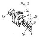
図2は、誘導エレメント46とのトルクに耐える係合のための、その外ねじ山34及び二つの対向する平らな外面50の一つを有するピストンロッド28を模式的な部分斜視図において示す。更に、ピストンロッド28の近位端32がはっきりと見られる。第一実施態様に記載の保持手段60は、図2において示されるように、誘導エレメント46内に挿入されている。 FIG. 2 shows in a schematic partial perspective view a
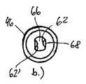
第一実施態様の保持手段60は、図3aから見ることができるように、実質的にU形を有するベントワイヤである。ベントワイヤは、好ましくは、ばね鋼でできており、そして「U」からの二つの分岐(branch-off)は、クランプ部分62、62’がピストンロッド28に対して凸形を誘導エレメント46内に挿入させて形成されるように、曲がっている。保持手段又は保持クランプ60はスリット46を通して誘導エレメント46中に挿入され、そして誘導エレメント46内に軸方向に固定して保持されるが、好ましくは、ピストンロッド28の軸に対して半径方向の面中における動きを可能にするための幾らかの遊びを有して保持されている。 The holding means 60 of the first embodiment is a bent wire having a substantially U shape, as can be seen from FIG. 3a. The vent wire is preferably made of spring steel, and the two branch-offs from “U” are such that the
誘導エレメント46中に挿入されると、保持手段60のクランプ部分62、62’は、開口部66の対応する平面の表面68を有するピストンロッド28の平らな外面50の機械的協力、特に係合のおかげで、トルクに耐えるような形で軸方向にピストンロッド28がその中に誘導されそして保持される開口部66中に、それらの各々の凸状のワイヤ部分を用いて突き出す。これは、図3aの矢印IIIに記載の近位端からの正面図である図3bにおいて最もよく見られる。 When inserted into the
このように、保持手段16はピストンロッド28上に自動的に中心を置かれている。 Thus, the holding means 16 is automatically centered on the
図4から6において描かれている第二実施態様によると、保持手段160はディスクを有し、ここで内側輪郭170は、それを通ってピストンロッド28が通過する開口部を画成する。保持手段160はプラスチックディスクでできており、そして輪郭170も、ピストンロッド28の二つの平面の表面50と接触している二つのクランプ部分162、162’を画成する。 According to the second embodiment depicted in FIGS. 4 to 6, the holding means 160 comprises a disk, where the
そのような保持ディスク160は、好ましくは、図1における参照符号52によって示されている通り、その遠位側上の誘導エレメント46に隣接して配置される。注射用量の投薬中に、保持ディスク160は誘導エレメント46又はハウジングの別の固定された部分に寄りかかり、従って、ハウジング部分14に対して軸方向に固定されるため、ピストンロッド28のための保持手段としてそれが作用することができる。 Such a
図6は、図4の線VI−VIに記載の簡略化された断面を示す。図6の右側の断面において、クランプ部分162、162’は保持位置にある。この位置において、各前面172、172’はピストンロッド28の各平らな外面50と完全接触状態にある。事前に設定された注射用量を投薬するために、ピストンロッド28が、軸方向に固定されたクランプディスク160に対して近位方向Mに動かされると、好ましくは弾性のクランプ部分162、162’が少し曲がり、そのためそれらは小さな領域、つまり、前面172、172’の端部面積174、174’とだけ接触する。そのような構成を有すると、図6の右側に記載の保持位置における静摩擦はかなり大きく、ここでピストンロッド28がクランプディスク162に対して動くときに、ピストンロッド28の前面172、172’と各外面50の間の減少した接触面積のせいで、本来より小さな動摩擦が、クランプ部分162、162’の曲がりによって更に最小化される。 FIG. 6 shows a simplified cross-section as described by line VI-VI in FIG. In the right cross section of FIG. 6, the
尚、図6の模式図においては、ピストンロッドの運動中の弾性変形の量が誇張されているので、矢印Mの方向へのピストンロッド28の動きが終わった後、クランプ部分162、162’は、ピストンロッド28の位置への何らの影響も無しに、図6(右手側)に記載の保持位置に無理やりに向かわされる。従って、休止位置(右手側)におけるクランプ部分162、162’の戻り運動のせいで、遠位方向(図6の矢印Mの反対方向)にピストンロッドが後退することはない。クランプ部分162、162’は弾性的復元力によって保持位置に無理やり向かわされる。 In the schematic diagram of FIG. 6, since the amount of elastic deformation during the movement of the piston rod is exaggerated, after the movement of the
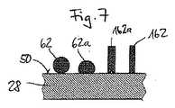
図7は、模式的なかつ簡略化された状態における、第一実施態様に記載のベントワイヤ60の断面の、及びディスク形をした保持手段160のクランプ部分162、162’のあり得る代替例を示す。そこに見られるように、左側の第一断面は円形断面を有する曲がった金属ワイヤからなる。或いは、この断面は、金属ワイヤとピストンロッド28の平面の表面50の間の接触面積を増すために円形セグメントであってもよい。更に、右側に、既に提案されたクランプ部分162に対する代替例があり、ここで代替クランプ部分162aは二つのリップ176によってピストン28の表面50と接触している前面172aを有する。そのような配置はまた、図6の左側において示されるように、ピストンロッド28の運動中、クランプ部分162の弾性的な小さい変形の場合にも有利であり得る。 FIG. 7 shows a possible alternative of the cross-section of the
ばね鋼のベントワイヤ又はプラスチックのディスクの形をした保持手段60、160によって、クランプ部分62及び62’、162,162’とピストンロッド28の平面の表面50の間の静摩擦のため、ピストンロッド28が保持され得る。この静摩擦は、注射機構26(図1)の内部摩擦による及び/又は注射機構26内又は注射デバイス10全体の遊びによる、ピストンロッド28の如何なる動きをも防ぐほど高い。ピストンロッド28の縦軸に対する保持手段60、160の対称的形態は、ピストンロッド28上の一定のクランプ作用に繋がる。クランプ部分62、62’及び162、162’の各々から働く力は、クランプ作用がハウジングによる半径方向に支持されるべき一方的な力を引き起こさないように、互いに緩和され、そのことがピストンロッドと注射デバイスの他の部分の間に作用する半径方向の応力を避ける自己センタリング効果をもたらす。 The holding means 60, 160 in the form of spring steel bent wires or plastic discs causes the
Claims (13)
Translated fromJapaneseここで、該機構は、
容器(16)から注射液(18)を投薬するために、ハウジング(12,14)に対して軸方向に変位可能であり、外ねじ山(34)を有し、そしてハウジング(12,14)に対してトルクに耐えるように配置される、ピストンロッド(28)、
該ピストンロッド(28)の外ねじ山に係合する内ねじ山(38)を有し、ハウジング(12,14)に対してその軸位置を変更可能なように設計され、そして注射用量の設定中、ピストンロッド(28)に対して、そしてハウジング(12,14)に対して回転可能であるねじ山付きエレメント(36)、を含む、用量設定手段
を含有し、
ここで、該用量設定手段(26)は、
ねじ山付きエレメント(36)及びピストンロッド(28)がハウジング(12,14)に対して軸方向に一緒に変位可能となる形で、事前設定注射用量の注射中、ねじ山付きエレメント(36)がピストンロッド(28)及びハウジング(12,14)に対してトルクに耐える形で、保持されるように設計され、
ここで、該機構(26)は、ピストンロッド(28)と接触する、そして注射用量の投薬を除いてデバイス(10)の使用中、ピストンロッド(28)の軸方向変位が実質的に固定化できるように設計される、保持手段(60)を更に含む、注射デバイス(10)であって、
ここで、該保持手段(60)がハウジング(12,14)に対して軸方向に固定されている、
ピストンロッド(28)は、外ねじ山(34)が切り込まれ、そしてピストンロッド(28)の対向する両側に互いに平行に配置される二つの平らな長手方向の外面(50)を有し、ここで保持手段(60)が、ピストンロッド(28)の両方の平行な外面(50)と接触し、そしてピストンロッド(28)に圧縮力を働かせる、
保持手段(60)が、各々がピストンロッド(28)の各々の平らな外面(50)と接触する二つのクランプ部分(62、62’)を有するクランプとして作用する、その保持手段(60)が、ベント金属ワイヤ(60)からできている、及び
クランプ部分(62、62’)が、ピストンロッド(28)の方向に凸である曲率を有する、上記注射デバイス(10)。Adapted to receive the container (16) with injection solution (18) in the proximal housing part (12) and to receive the dose setting and injection mechanism (26) in the distal housing part (14). An injection device (10) comprising a housing (12, 14),
Here, the mechanism is
For dispensing the injection solution (18) from the container (16), it is axially displaceable relative to the housing (12, 14), has an external thread (34), and the housing (12, 14). A piston rod (28), arranged to withstand torque against
Designed to have an inner thread (38) that engages the outer thread of the piston rod (28) and to be able to change its axial position relative to the housing (12, 14) and to set the injection dose A dose setting means comprising a threaded element (36) that is rotatable relative to the piston rod (28) and relative to the housing (12, 14);
Here, the dose setting means (26)
During the injection of the preset injection dose, the threaded element (36), such that the threaded element (36) and the piston rod (28) are axially displaceable together relative to the housing (12, 14). Is designed to be held in a torque resistant manner against the piston rod (28) and the housing (12, 14),
Here, the mechanism (26) is in contact with the piston rod (28), and the axial displacement of the piston rod (28) is substantially fixed during use of the device (10) except for injection dose administration. An injection device (10) further comprising holding means (60) designed to allow
Wherein said holding means(6 0)that is fixed axially relative to the housing (12,14),
The piston rod (28) has two flat longitudinal outer surfaces (50) which are threaded with external threads (34) and are arranged parallel to each other on opposite sides of the piston rod (28); Here, the holding means (60) are in contact with both parallel outer surfaces (50) of the piston rod (28) and exert a compressive force on the piston rod (28).
The retaining means (60) acts as a clamp having two clamping portions (62, 62 ') each contacting the respective flat outer surface (50) of the piston rod (28). Made of bent metal wire (60), and
The injection device (10), wherein theclamping portion (62, 62 ') has a curvature that is convex in the direction of the piston rod (28 ).
Applications Claiming Priority (3)
| Application Number | Priority Date | Filing Date | Title |
|---|---|---|---|
| EP08021046 | 2008-12-04 | ||
| EP08021046.1 | 2008-12-04 | ||
| PCT/EP2009/066094WO2010063687A1 (en) | 2008-12-04 | 2009-12-01 | Injection device with holding means to prevent unintentional movements of piston rod |
Publications (2)
| Publication Number | Publication Date |
|---|---|
| JP2012510836A JP2012510836A (en) | 2012-05-17 |
| JP5622743B2true JP5622743B2 (en) | 2014-11-12 |
Family
ID=41017119
Family Applications (1)
| Application Number | Title | Priority Date | Filing Date |
|---|---|---|---|
| JP2011538986AActiveJP5622743B2 (en) | 2008-12-04 | 2009-12-01 | Injection device having holding means for preventing unintentional movement of the piston rod |
Country Status (22)
| Country | Link |
|---|---|
| US (3) | US8915881B2 (en) |
| EP (1) | EP2373362B1 (en) |
| JP (1) | JP5622743B2 (en) |
| KR (1) | KR101677068B1 (en) |
| CN (1) | CN102238974B (en) |
| AU (1) | AU2009324174B2 (en) |
| BR (1) | BRPI0922692B8 (en) |
| CA (1) | CA2745077A1 (en) |
| DK (1) | DK2373362T3 (en) |
| ES (1) | ES2648867T3 (en) |
| HU (1) | HUE035759T2 (en) |
| IL (1) | IL213327A (en) |
| MX (1) | MX2011004660A (en) |
| MY (1) | MY154862A (en) |
| NO (1) | NO2373362T3 (en) |
| NZ (1) | NZ593248A (en) |
| PL (1) | PL2373362T3 (en) |
| RU (1) | RU2526438C2 (en) |
| SG (1) | SG171946A1 (en) |
| TW (1) | TWI522138B (en) |
| WO (1) | WO2010063687A1 (en) |
| ZA (1) | ZA201102842B (en) |
Cited By (1)
| Publication number | Priority date | Publication date | Assignee | Title |
|---|---|---|---|---|
| CN103467268A (en)* | 2013-09-26 | 2013-12-25 | 山东午阳化工股份有限公司 | Preparation method of 2,2'- dyhydroxyl-4,4'-dimethoxybenzophenone |
Families Citing this family (26)
| Publication number | Priority date | Publication date | Assignee | Title |
|---|---|---|---|---|
| FR2953415B1 (en)* | 2009-12-09 | 2012-12-28 | Primequal Sa | EJECTION DEVICE FOR EJECTING LOW DOSES |
| WO2011097742A1 (en)* | 2010-02-12 | 2011-08-18 | Medmix Systems Ag | Discharge device having a locking element |
| JP5946460B2 (en) | 2010-10-13 | 2016-07-06 | サノフィ−アベンティス・ドイチュラント・ゲゼルシャフト・ミット・ベシュレンクテル・ハフツング | Dose setting mechanism for drug delivery devices |
| US9364616B2 (en)* | 2011-07-14 | 2016-06-14 | Sanofi-Aventis Deutschland Gmbh | Drive mechanism of a drug delivery device |
| AR088689A1 (en)* | 2011-11-09 | 2014-06-25 | Sanofi Aventis Deutschland | DRIVE ASSEMBLY FOR A MEDICATION ADMINISTRATION DEVICE AND A MEDICATION ADMINISTRATION DEVICE THAT INCLUDES A DRIVE ASSEMBLY |
| JP2015505253A (en)* | 2011-12-06 | 2015-02-19 | ノボ・ノルデイスク・エー/エス | Drive mechanism for an injection device and method of assembling an injection device comprising such a drive mechanism |
| US10213556B2 (en) | 2011-12-08 | 2019-02-26 | Unl Holdings Llc | Accurate dose control mechanisms and drug delivery syringes |
| PT2788054T (en)* | 2011-12-08 | 2018-07-30 | Unl Holdings Llc | Accurate dose control mechanisms and drug delivery syringes |
| US10328211B2 (en) | 2011-12-08 | 2019-06-25 | Unl Holdings Llc | Automatic self-dispensing accurate dose drug delivery syringes |
| CN103974731B (en)* | 2011-12-08 | 2017-09-19 | 赛诺菲-安万特德国有限公司 | Drive assembly for a medicament delivery device and medicament delivery device comprising a drive assembly |
| DE102013007389A1 (en)* | 2013-04-30 | 2014-10-30 | Britannia Pharmaceuticals Ltd. | Drug delivery device |
| CN103637856B (en)* | 2013-11-14 | 2015-09-09 | 燕海峰 | Singlehanded direct press type continuous and quantitative liquid sucking-discharging device |
| GB2529621B (en)* | 2014-08-21 | 2016-12-07 | Owen Mumford Ltd | Safety syringe |
| WO2016174213A1 (en)* | 2015-04-29 | 2016-11-03 | Novo Nordisk A/S | Drug delivery device with spring mechanism |
| EP3181170A1 (en) | 2015-12-14 | 2017-06-21 | Sanofi-Aventis Deutschland GmbH | Drive mechanism for an injection device |
| CN105727400B (en)* | 2016-02-03 | 2023-02-17 | 苏州翰尔西医疗器械开发有限公司 | drug delivery device |
| CN109069754B (en)* | 2016-04-15 | 2021-09-07 | 参天制药株式会社 | Accurate, precise microliter dose syringes |
| KR102231847B1 (en) | 2016-05-27 | 2021-03-26 | 에스에이치엘 메디컬 아게 | Working mechanism |
| US10926038B2 (en) | 2016-11-01 | 2021-02-23 | Credence Medsystems, Inc. | System and method for safety syringe |
| CN110709122B (en)* | 2017-04-13 | 2023-04-11 | 贝克顿·迪金森公司 | Controlled delivery syringe device |
| FR3072297B1 (en)* | 2017-10-17 | 2023-05-12 | Edix Sa | MANUAL INJECTION DEVICE |
| CN111886038A (en) | 2018-03-27 | 2020-11-03 | 艾斯曲尔医疗公司 | Drive mechanism and drug delivery device including the same |
| CN109172952B (en)* | 2018-10-08 | 2023-09-26 | 东曜药业有限公司 | Syringe and auxiliary dosing device for a syringe |
| CN120022470A (en) | 2019-11-14 | 2025-05-23 | 和谐医疗解决方案有限责任公司 | Variable dose syringes |
| CN116328102B (en)* | 2023-05-31 | 2023-08-01 | 四川省医学科学院·四川省人民医院 | Injection device for diabetes |
| CN120381582B (en)* | 2025-06-30 | 2025-10-03 | 苏州嘉树医疗科技有限公司 | Dose adjusting mechanism of injection device and injection device |
Family Cites Families (14)
| Publication number | Priority date | Publication date | Assignee | Title |
|---|---|---|---|---|
| DE331326C (en)* | 1921-01-05 | Carl Braun | Head for guiding the plunger rod in injection or similar medical syringes | |
| GB551545A (en)* | 1942-01-13 | 1943-02-26 | Samuel James Everett | Improvements in or relating to hypodermic and like syringes |
| BE538443A (en)* | 1955-04-04 | |||
| IE52621B1 (en) | 1981-02-12 | 1988-01-06 | Turner Robert Charles | Dose metering plunger devices for use with syringes |
| AU641206B2 (en) | 1991-01-22 | 1993-09-16 | Eli Lilly And Company | Multiple dose injection pen |
| JPH0611337B2 (en)* | 1991-02-07 | 1994-02-16 | イーライ・リリー・アンド・カンパニー | Syringe and dosage adjustment device |
| US5545147A (en)* | 1992-10-20 | 1996-08-13 | Eli Lilly And Company | Anti-backup improvement for hypodermic syringes |
| US5320609A (en)* | 1992-12-07 | 1994-06-14 | Habley Medical Technology Corporation | Automatic pharmaceutical dispensing syringe |
| US6800071B1 (en)* | 1998-10-29 | 2004-10-05 | Medtronic Minimed, Inc. | Fluid reservoir piston |
| DE29900482U1 (en) | 1999-01-14 | 2000-08-31 | Medico Development Investment Co., Ascona | Injection device |
| GB0007071D0 (en)* | 2000-03-24 | 2000-05-17 | Sams Bernard | One-way clutch mechanisms and injector devices |
| DE10163327A1 (en)* | 2001-07-30 | 2003-02-27 | Disetronic Licensing Ag | Reservoir module with piston rod |
| DE20112501U1 (en)* | 2001-07-30 | 2002-12-19 | Disetronic Licensing Ag, Burgdorf | Locking lock for connecting housing parts of an injection or infusion device |
| DE20317377U1 (en)* | 2003-11-03 | 2005-03-17 | B D Medico S A R L | injection device |
- 2009
- 2009-12-01AUAU2009324174Apatent/AU2009324174B2/enactiveActive
- 2009-12-01JPJP2011538986Apatent/JP5622743B2/enactiveActive
- 2009-12-01EPEP09764784.6Apatent/EP2373362B1/enactiveActive
- 2009-12-01HUHUE09764784Apatent/HUE035759T2/enunknown
- 2009-12-01CACA2745077Apatent/CA2745077A1/ennot_activeAbandoned
- 2009-12-01WOPCT/EP2009/066094patent/WO2010063687A1/enactiveApplication Filing
- 2009-12-01SGSG2011040581Apatent/SG171946A1/enunknown
- 2009-12-01NONO09764784Apatent/NO2373362T3/nounknown
- 2009-12-01CNCN200980148715.9Apatent/CN102238974B/enactiveActive
- 2009-12-01BRBRPI0922692Apatent/BRPI0922692B8/enactiveIP Right Grant
- 2009-12-01KRKR1020117012548Apatent/KR101677068B1/enactiveActive
- 2009-12-01PLPL09764784Tpatent/PL2373362T3/enunknown
- 2009-12-01ESES09764784.6Tpatent/ES2648867T3/enactiveActive
- 2009-12-01MXMX2011004660Apatent/MX2011004660A/enactiveIP Right Grant
- 2009-12-01RURU2011127107/14Apatent/RU2526438C2/enactive
- 2009-12-01DKDK09764784.6Tpatent/DK2373362T3/enactive
- 2009-12-01USUS13/126,321patent/US8915881B2/enactiveActive
- 2009-12-01MYMYPI2011001749Apatent/MY154862A/enunknown
- 2009-12-01NZNZ593248Apatent/NZ593248A/ennot_activeIP Right Cessation
- 2009-12-02TWTW098141088Apatent/TWI522138B/enactive
- 2011
- 2011-04-15ZAZA2011/02842Apatent/ZA201102842B/enunknown
- 2011-06-02ILIL213327Apatent/IL213327A/enactiveIP Right Grant
- 2014
- 2014-11-18USUS14/546,319patent/US20150141933A1/ennot_activeAbandoned
- 2015
- 2015-02-27USUS14/634,037patent/US9415170B2/enactiveActive
Cited By (1)
| Publication number | Priority date | Publication date | Assignee | Title |
|---|---|---|---|---|
| CN103467268A (en)* | 2013-09-26 | 2013-12-25 | 山东午阳化工股份有限公司 | Preparation method of 2,2'- dyhydroxyl-4,4'-dimethoxybenzophenone |
Also Published As
Similar Documents
| Publication | Publication Date | Title |
|---|---|---|
| JP5622743B2 (en) | Injection device having holding means for preventing unintentional movement of the piston rod | |
| CN204337431U (en) | Medication delivery pens | |
| JP4718462B2 (en) | Three-threaded drug delivery device for mechanical advantage | |
| JP5588998B2 (en) | Fixed dose injection device with resettable drive mechanism | |
| CN105188811B (en) | injection equipment | |
| JP2009513167A (en) | Liquid drug administration device | |
| JP6412946B2 (en) | Injector | |
| JPH0567308B2 (en) | ||
| KR20170026561A (en) | Drug delivery device | |
| US20130030381A1 (en) | Drive Assembly for a Drug Delivery Device and Drug Delivery Device | |
| US20060264838A1 (en) | Device for expelling a liquid or pasty substance | |
| AU2015269605A1 (en) | Rotatable end of dose feedback mechanism | |
| JP6718959B2 (en) | Automatic injector with dosing device | |
| JP2018529462A (en) | Syringe | |
| JP4593632B2 (en) | Dosage setting mechanism for injection device with gear | |
| CN211986546U (en) | Housing for an injection device for delivering a medicament and injection device | |
| US11103643B2 (en) | Bi-directional rotation resistant friction pad | |
| HK1158995B (en) | Injection device with holding means to prevent unintentional movements of piston rod |
Legal Events
| Date | Code | Title | Description |
|---|---|---|---|
| A621 | Written request for application examination | Free format text:JAPANESE INTERMEDIATE CODE: A621 Effective date:20121122 | |
| A977 | Report on retrieval | Free format text:JAPANESE INTERMEDIATE CODE: A971007 Effective date:20131029 | |
| A131 | Notification of reasons for refusal | Free format text:JAPANESE INTERMEDIATE CODE: A131 Effective date:20131217 | |
| A521 | Request for written amendment filed | Free format text:JAPANESE INTERMEDIATE CODE: A523 Effective date:20140314 | |
| TRDD | Decision of grant or rejection written | ||
| A01 | Written decision to grant a patent or to grant a registration (utility model) | Free format text:JAPANESE INTERMEDIATE CODE: A01 Effective date:20140826 | |
| A61 | First payment of annual fees (during grant procedure) | Free format text:JAPANESE INTERMEDIATE CODE: A61 Effective date:20140922 | |
| R150 | Certificate of patent or registration of utility model | Ref document number:5622743 Country of ref document:JP Free format text:JAPANESE INTERMEDIATE CODE: R150 | |
| R250 | Receipt of annual fees | Free format text:JAPANESE INTERMEDIATE CODE: R250 | |
| R250 | Receipt of annual fees | Free format text:JAPANESE INTERMEDIATE CODE: R250 | |
| R250 | Receipt of annual fees | Free format text:JAPANESE INTERMEDIATE CODE: R250 | |
| R250 | Receipt of annual fees | Free format text:JAPANESE INTERMEDIATE CODE: R250 | |
| R250 | Receipt of annual fees | Free format text:JAPANESE INTERMEDIATE CODE: R250 | |
| R250 | Receipt of annual fees | Free format text:JAPANESE INTERMEDIATE CODE: R250 | |
| R250 | Receipt of annual fees | Free format text:JAPANESE INTERMEDIATE CODE: R250 | |
| R250 | Receipt of annual fees | Free format text:JAPANESE INTERMEDIATE CODE: R250 |