JP5617304B2 - Switching device, information processing device, and fault notification control program - Google Patents
Switching device, information processing device, and fault notification control programDownload PDFInfo
- Publication number
- JP5617304B2 JP5617304B2JP2010073476AJP2010073476AJP5617304B2JP 5617304 B2JP5617304 B2JP 5617304B2JP 2010073476 AJP2010073476 AJP 2010073476AJP 2010073476 AJP2010073476 AJP 2010073476AJP 5617304 B2JP5617304 B2JP 5617304B2
- Authority
- JP
- Japan
- Prior art keywords
- information
- mib
- management
- management information
- failure
- Prior art date
- Legal status (The legal status is an assumption and is not a legal conclusion. Google has not performed a legal analysis and makes no representation as to the accuracy of the status listed.)
- Active
Links
Images


Classifications
- H—ELECTRICITY
- H04—ELECTRIC COMMUNICATION TECHNIQUE
- H04L—TRANSMISSION OF DIGITAL INFORMATION, e.g. TELEGRAPHIC COMMUNICATION
- H04L41/00—Arrangements for maintenance, administration or management of data switching networks, e.g. of packet switching networks
- H04L41/06—Management of faults, events, alarms or notifications
Landscapes
- Engineering & Computer Science (AREA)
- Computer Networks & Wireless Communication (AREA)
- Signal Processing (AREA)
- Computer And Data Communications (AREA)
- Data Exchanges In Wide-Area Networks (AREA)
Description
Translated fromJapanese本発明は、スイッチング装置、情報処理装置および障害通知制御プログラムに関する。 The present invention relates to a switching device, an information processing device, and a failure notification control program.
従来、スイッチやファイバチャネルスイッチ(FCスイッチ)等のネットワーク機器を有するネットワークシステムを監視し管理する手法として、SNMP(Simple Network Management Protocol)が利用されている。 Conventionally, SNMP (Simple Network Management Protocol) has been used as a technique for monitoring and managing a network system having network devices such as switches and fiber channel switches (FC switches).
SNMPによる監視手法は、監視対象機器からMIB(Management Information Base)情報を収集して監視対象機器の状態を判断するSNMPマネージャと、SNMPマネージャにMIB情報を送信するSNMPエージェントとを有して形成される。SNMPマネージャは、例えば10台から100台規模のSNMPエージェントからMIB情報を収集し、収集したMIB情報に基づいて障害を検知する。 The SNMP monitoring method is formed by having an SNMP manager that collects MIB (Management Information Base) information from monitored devices to determine the status of the monitored device, and an SNMP agent that transmits MIB information to the SNMP manager. The The SNMP manager collects MIB information from, for example, 10 to 100 SNMP agents, and detects a failure based on the collected MIB information.
例えば、SNMPマネージャを有する管理装置(以下、管理装置という)は、SNMPエージェントを有し監視対象であるネットワーク機器(以下、監視対象機器という)各々のMIB定義ファイルを記憶する。また、SNMPエージェントを有するネットワーク機器は、監視対象のオブジェクトを識別する「OID」と、監視対象のオブジェクトの状態を示す「状態情報」とを対応付けた「MIB情報」を格納するMIB情報格納領域を有する。なお、MIB定義ファイルもMIB情報と同様の情報を有する。 For example, a management device having an SNMP manager (hereinafter referred to as a management device) stores an MIB definition file of each network device (hereinafter referred to as a monitoring target device) that has an SNMP agent and is a monitoring target. The network device having the SNMP agent also stores an MIB information storage area for storing “MIB information” in which “OID” that identifies the object to be monitored and “status information” that indicates the state of the object to be monitored are associated with each other. Have The MIB definition file also has the same information as the MIB information.
このような状態において、管理装置は、監視対象機器からMIB情報として、例えば「OID」などの情報を受信した場合に、受信したOIDに基づいて自装置が記憶するMIB定義ファイルから「状態情報」を特定する。つまり、管理装置は、監視対象機器から受信したMIB情報によって、機器の状態を特定している。したがって、管理装置のMIB定義ファイルで管理されるMIB情報と、監視対象機器のMIBで管理されるMIB情報とが一致している必要がある。 In such a state, when the management apparatus receives information such as “OID” as MIB information from the monitoring target device, the management apparatus “state information” from the MIB definition file stored in the self apparatus based on the received OID. Is identified. That is, the management apparatus specifies the state of the device based on the MIB information received from the monitoring target device. Therefore, the MIB information managed by the MIB definition file of the management apparatus needs to match the MIB information managed by the MIB of the monitoring target device.
例えば、ファームウェアのバージョンによってMIB情報が異なる例について説明する。例えば、ファームウェアのバージョンアップ前(バージョン=6.3.0a)のMIB情報では、「OID、状態情報」として「1.3.x.x.x.1、ON」、「1.3.x.x.x.2、OFF」、「1.3.x.x.x.3、restart」などを有するMIBツリーが記憶される。また、ファームウェアのバージョンアップ後(バージョン=6.3.0b)のMIB情報では、「OID、状態情報」として「1.3.x.x.x.1、ON」、「1.3.x.x.x.2、restart」、「1.3.x.x.x.3、OFF」などを有するMIBツリーが記憶される。 For example, an example in which the MIB information varies depending on the firmware version will be described. For example, in the MIB information before firmware upgrade (version = 6.3.0a), “OID, status information” is “1.3.xxx1, ON”, “1.3.xxx2, OFF”, “1.3.xxx3, The MIB tree having “restart” or the like is stored. In the MIB information after firmware upgrade (version = 6.3.0b), “OID, status information” is “1.3.xxx1, ON”, “1.3.xxx2, restart”, “1.3.xxx3, A MIB tree having “OFF” or the like is stored.
これらを比較すると、「OID=1.3.x.x.x.2」と「OID=1.3.x.x.x.3」の示す値が異なることがわかる。この場合に、例えば、管理装置がバージョンアップ前のMIB情報を記憶し、監視対象機器がバージョンアップ後のMIB情報を記憶していた場合に、監視対象機器が「OID報=1.3.x.x.x.2」を管理装置に送信する。この場合、監視装置は、「OID=1.3.x.x.x.2」によって「機器状態=restart」を特定するが、監視対象機器は、「OID=1.3.x.x.x.2」に対応する「機器状態=OFF」の状態である。つまり、監視装置は、監視対象機器の状態を誤って特定することとなる。 Comparing these, it can be seen that the values indicated by “OID = 1.3.x.x.x.2” and “OID = 1.3.x.x.x.3” are different. In this case, for example, when the management device stores the MIB information before the upgrade and the monitored device stores the MIB information after the upgrade, the monitoring target device is “OID information = 1.3.xxx2”. Is transmitted to the management apparatus. In this case, the monitoring device specifies “device state = restart” by “OID = 1.3.xxx2”, but the monitoring target device has “device state = OFF” corresponding to “OID = 1.3.xxx2”. State. That is, the monitoring device erroneously specifies the state of the monitoring target device.
このように、監視対象機器が管理するMIB情報は、管理対象機器が有するファームウェアのバージョンによって変更されるため、ファームウェアのバージョンアップに伴って、管理装置が記憶するMIB定義ファイルの更新も実行される。 As described above, the MIB information managed by the monitoring target device is changed depending on the firmware version of the management target device. Therefore, the update of the MIB definition file stored in the management apparatus is also executed with the firmware version upgrade. .
しかしながら、従来の技術では、SNMPエージェントが保持しているMIB情報とSNMPマネージャ側が保持しているMIB情報とは、それぞれで管理されているため、SNMPエージェント側とSNMPマネージャ側とで更新状況が異なる場合がある。すなわち、ネットワーク機器を管理する管理側と管理対象となる機器側との間で、障害の検出等に共通して利用されるネットワーク機器の管理情報が不一致となる。このように、SNMPエージェント側とSNMPマネージャ側との間で管理される管理情報の更新状況が異なる場合に、SNMPによる監視および管理を正確に実施することができないという課題があった。 However, in the conventional technique, the MIB information held by the SNMP agent and the MIB information held by the SNMP manager are managed separately, so that the update status differs between the SNMP agent and the SNMP manager. There is a case. That is, the management information of the network device that is commonly used for detecting a failure or the like does not match between the management side that manages the network device and the device side to be managed. As described above, there is a problem in that monitoring and management by SNMP cannot be performed accurately when the management information managed on the SNMP agent side and the SNMP manager side are different.
例えば、上述したように、ファームアップなどによってSNMPエージェント側のMIB情報が変更された場合に、遅滞無く、SNMPマネージャ側のMIB情報を変更する必要がある。そして、SNMPマネージャのMIB情報を更新する場合には、SNMPマネージャを停止する、言い換えると、SNMPによる監視管理システムを停止する必要がある。 For example, as described above, when the MIB information on the SNMP agent side is changed due to a firmware upgrade or the like, it is necessary to change the MIB information on the SNMP manager side without delay. When updating the MIB information of the SNMP manager, it is necessary to stop the SNMP manager, in other words, stop the SNMP monitoring management system.
一方で、SNMPマネージャは、大規模であれば100台以上になるSNMPエージェントを管理対象としているため、システム停止を行うとシステム全体の運用に支障をきたす。このため、SNMPマネージャのMIB情報については、スケジューリングを行い、システム運用にきたさないタイミングで更新することとなる。 On the other hand, since the SNMP manager manages more than 100 SNMP agents in a large scale, if the system is stopped, the operation of the entire system is hindered. Therefore, the MIB information of the SNMP manager is scheduled and updated at a timing that does not lead to system operation.
したがって、SNMPエージェント側のMIB情報が変更されたにも関わらず、SNMPマネージャ側のMIB情報が変更されていない状態が発生し、この間は、SNMPエージェント側とSNMPマネージャ側のMIB情報が異なる。この結果、SNMPによる監視および管理を正確に実施することができない事象が発生する。 Therefore, although the MIB information on the SNMP agent side is changed, the MIB information on the SNMP manager side is not changed. During this time, the MIB information on the SNMP agent side and the SNMP manager side is different. As a result, an event in which monitoring and management by SNMP cannot be performed accurately occurs.
開示の技術は、上記に鑑みてなされたものであって、SNMPエージェント側とSNMPマネージャ側との間で管理される管理情報の更新状況が異なる場合でも、SNMPによる監視および管理を正確に実施することが可能であるスイッチング装置、情報処理装置および障害通知制御プログラムを提供することを目的とする。 The disclosed technology has been made in view of the above, and accurately performs monitoring and management by SNMP even when the management information update status is different between the SNMP agent side and the SNMP manager side. An object of the present invention is to provide a switching device, an information processing device, and a failure notification control program.
本願の開示するスイッチング装置は、一つの態様において、更新された管理情報を示す更新後管理情報と更新される前の管理情報を示す更新前管理情報とを記憶する管理情報記憶部と、障害監視対象装置で発生した障害を管理する管理装置が記憶する管理情報を特定する情報を取得し、取得された情報に基づいて、前記管理情報記憶部に記憶される管理情報のうち前記管理装置が記憶する管理情報を特定する管理情報特定部と、障害を検知した場合に、前記管理情報特定部によって特定された管理情報に基づいて、障害情報を前記管理装置に送信する情報送信部とを有する。 In one aspect, the switching device disclosed in the present application includes a management information storage unit that stores post-update management information indicating updated management information and pre-update management information indicating management information before being updated, and fault monitoring Information for identifying management information stored in a management device that manages a failure that has occurred in the target device is acquired, and the management device stores the management information stored in the management information storage unit based on the acquired information A management information specifying unit that specifies management information to be transmitted; and an information transmission unit that transmits failure information to the management apparatus based on the management information specified by the management information specifying unit when a failure is detected.
本願の開示するスイッチング装置、情報処理装置および障害通知制御プログラムの一つの態様によれば、SNMPエージェント側とSNMPマネージャ側との間で管理される管理情報の更新状況が異なる場合でも、SNMPによる監視および管理を正確に実施することが可能であるという効果を奏する。 According to one aspect of the switching device, the information processing device, and the failure notification control program disclosed in the present application, even when the update status of management information managed between the SNMP agent side and the SNMP manager side is different, monitoring by SNMP In addition, there is an effect that the management can be performed accurately.
以下に、本願の開示するスイッチング装置、情報処理装置および障害通知制御プログラムの実施例を図面に基づいて詳細に説明する。なお、この実施例によりこの発明が限定されるものではない。 Embodiments of a switching device, an information processing device, and a failure notification control program disclosed in the present application will be described below in detail with reference to the drawings. Note that the present invention is not limited to the embodiments.
実施例1では、本願の開示するスイッチング装置をFC(Fibre Channel)スイッチに適した例について説明する。ここでは、FCスイッチを含む全体構成、FCスイッチの構成、FCによる処理の流れ、実施例1による効果を順に説明する。なお、本実施例では、管理情報としてMIB情報を用いた例を説明するが、これに限定されるものではなく、ネットワーク機器等を管理できる機器管理情報であれば、どのような情報でも適用できる。 In the first embodiment, an example in which the switching device disclosed in the present application is suitable for an FC (Fibre Channel) switch will be described. Here, the overall configuration including the FC switch, the configuration of the FC switch, the flow of processing by the FC, and the effect of the first embodiment will be described in order. In the present embodiment, an example in which MIB information is used as management information will be described. However, the present invention is not limited to this, and any information can be applied as long as it is device management information capable of managing network devices and the like. .
[全体構成]
図1は、実施例1に係るFCスイッチを含むシステムの全体構成を示す図である。図1に示すように、このシステムは、管理装置1とサーバ5とサーバ6とFCスイッチ10とストレージ50とを有するシステムであり、いわゆるSAN(Storage Area Network)を形成する。ストレージ50は、複数のディスクを有し、サーバ5やサーバ6が利用するデータを記憶する記憶装置である。なお、図1に示した各装置の台数等は、あくまで例示であり、これに限定されるものではない。[overall structure]
FIG. 1 is a diagram illustrating an overall configuration of a system including an FC switch according to the first embodiment. As shown in FIG. 1, this system is a system having a management device 1, a
管理装置1は、SNMP(Simple Network Management Protocol)マネージャの機能を有するパーソナルコンピュータやサーバであり、サーバ5、サーバ6、FCスイッチ10のそれぞれとLAN(Local Area Network)等のネットワークで接続される。また、管理装置1は、SNMPエージェントごとに、MIB情報を記憶するMIB定義ファイルを有し、障害監視対象装置で発生した障害を管理する。そして、管理装置1は、SNMPエージェントからMIB情報を受信して、送信元のSNMPエージェントを有する機器の状態や障害を検出して管理する。 The management device 1 is a personal computer or server having a function of a Simple Network Management Protocol (SNMP) manager, and is connected to each of the
サーバ5とサーバ6は、ファイバーチャネルで接続されるFCスイッチ10を介してストレージ50と接続され、ストレージ50に対してデータの書き込みやストレージ50からデータの読出しを実行するサーバである。 The
FCスイッチ10は、SNMPエージェント機能を有するスイッチング装置であり、SNMPによるTrap制御等によって、SNMPマネージャの管理装置1に対してMIB情報を送信する。例えば、FCスイッチ10は、管理者等によって予め指定されたイベントが発生した場合や、送受信パケット数、エラーパケット数、CPU(Central Processing Unit)使用率などが閾値を超過した場合に、該当するMIB情報を管理装置1に送信する。また、FCスイッチ10は、サーバ5、サーバ6、ストレージ50のそれぞれとファイバーチャネルで接続され、管理装置1とLANで接続される。そして、FCスイッチ10は、サーバ5やサーバ6からストレージ50に対するアクセスや他のサーバ等へのアクセスを受け付けた場合に、自装置が有するルーティング情報にしたがってアクセスを制御する。 The
このFCスイッチ10は、更新されたMIBを示す更新後MIBと更新される前のMIBを示す更新前MIBとを記憶する。そして、FCスイッチ10は、障害を管理する管理装置1が記憶するMIBに関する情報を取得し、取得されたMIBに関する情報に基づいて、自装置に記憶されるMIBのうち管理装置1が記憶するMIBを特定する。言い換えると、FCスイッチ10は、管理装置1が記憶するMIBを特定する情報を取得て、自装置に記憶されるMIBのうち管理装置1が記憶するMIBを特定する。その後、FCスイッチ10は、障害を検知した場合に、特定されるMIBに基づくMIB情報を用いて当該障害の情報を管理装置1に送信する。 The FC switch 10 stores an updated MIB indicating the updated MIB and an unupdated MIB indicating the MIB before being updated. The
このように、FCスイッチ10は、管理装置1がMIB定義ファイルで管理するMIB情報にあわせたMIBを用いて、障害情報を送信することができる。この結果、SNMPエージェント側とSNMPマネージャ側との間で管理されるMIB情報の更新状況が異なる場合でも、SNMPによる監視および管理を正確に実施することが可能である。 As described above, the
[FCスイッチの構成]
次に、図2を用いて、図1に示したFCスイッチ10の構成を説明する。図2は、実施例1に係るFCスイッチの構成を示すブロック図である。図2に示すように、FCスイッチ10は、LANポート11と、FCポート12a〜12nと、制御回路13と、メモリ14と、記憶部15と、制御部20とを有する。[Configuration of FC switch]
Next, the configuration of the
LANポート11は、LANケーブルを接続する通信インタフェースであり、管理装置1のようにLAN等のネットワークに接続される装置との通信を制御する。例えば、LANポート11は、管理装置1からMIBバージョン情報等を受信し、また、管理装置1に対してMIB情報を送信する。 The
FCポート12a〜12nは、ファイバチャネル(FC)を接続する通信インタフェースであり、サーバ5やサーバ6のようにFCに接続される装置との通信を制御する。例えば、FCポート12a〜12nは、サーバ5やサーバ6からストレージ50へのデータ書き込み要求やデータ読出し要求を受信し、また、各要求に対する応答を送信元のサーバに送信する。なお、FCポート12aは、サーバ5に接続されるなど接続形態やポートの数は、システムの特性や管理形態によって任意に設定変更することができる。 The
制御回路13は、例えばASIC(Application Specific Integrated Circuit)などの集積回路であり、FCポート12a〜12nのルーティングを制御する。例えば、制御回路13は、後述するスイッチング制御部21によって生成されたルーティング情報に基づいて、FCポートで受信されたデータを宛先に送信する。具体的には、制御回路13は、FCポート12aから受信したデータをFCポート12fに送信し、また、FCポート12gから受信したデータをFCポート12eに送信する。なお、制御回路13は、スイッチング制御部21によってメモリ14に格納されたルーティング情報を参照してルーティング制御してもよく、また、スイッチング制御部21の指示によってルーティング情報を回路に反映させてルーティング制御してもよい。 The
メモリ14は、FCポート12a〜12nに関するルーティング情報やLANポート11に関するルーティング情報などを記憶するRAM(Random Access Memory)などの記憶装置である。なお、メモリ14が記憶する各ルーティング情報は、後述するスイッチング制御部21によって生成されて格納される。 The
記憶部15は、制御部20による各種処理に必要なデータおよびプログラムを格納する半導体メモリ素子、ハードディスク、コンパクトフラッシュ(登録商標)などの記憶装置であり、例えば、MIB蓄積DB16とMIBログDB17とを有する。なお、記憶部15が記憶する各種プログラム等は、制御部20の実行によって、メモリ14上に読み出される。 The
MIB蓄積DB16は、制御部20が有する各制御部やSNMPエージェントのバージョンアップによって更新される前のMIBを示す旧MIB情報16aと、更新されたMIBを示す新MIB情報16bとを記憶する。なお、ここでは、2世代のバージョンを記憶する例を示したが、これに限定されるものではなく、任意の世代数を記憶することもできる。 The
例えば、MIB蓄積DB16は、図3に示すように、「バージョン=6.3.0a」のMIB情報として、監視対象のオブジェクトを識別する「OID」と監視対象のオブジェクトの状態を示す「状態情報」と対応付けた旧MIB情報16aを記憶する。具体的には、MIB蓄積DB16は、旧MIB情報16aとして、「OID、状態情報」を「1.3.x.x.x.x.1、ON」、「1.3.x.x.x.x.2、OFF」、「1.3.x.x.x.x.3、restart」などと記憶する。なお、図3は、MIB蓄積DBに旧MIB情報として記憶される情報の例を示す図である。 For example, as shown in FIG. 3, the
また、新MIB情報16bは、図4に示すように、「バージョン=6.3.0b」のMIB情報として、旧MIB情報16aと同様に、「OID」と「状態情報」とを対応付けた新MIB情報16bを記憶する。具体的には、MIB蓄積DB16は、新MIB情報16bとして、「OID、状態情報」を「1.3.x.x.x.x.1、ON」、「1.3.x.x.x.x.2、restart」、「1.3.x.x.x.x.3、OFF」などとを記憶する。なお、図4は、MIB蓄積DBに新MIB情報として記憶される情報の例を示す図である。 Further, as shown in FIG. 4, the
また、MIB蓄積DB16に記憶される旧MIB情報16aや新MIB情報16bは、制御部20が有する各制御部やSNMPエージェントのバージョンアップによって自動的に更新されてもよく、管理者等によって手動で更新されてもよい。また、制御部20が有する各制御部がファームウェアで実現される場合には、ファームウェアのバージョンアップに伴って、自動的にアップロードされようにすることもできる。 Further, the
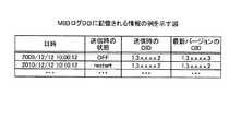
MIBログDB17は、管理装置1に送信されたMIB情報と、管理装置1にMIB情報が送信された時点でのFCスイッチの実際の状態とを対応付けたログを記憶する。例えば、MIBログDB17は、図5に示すように、「日時、送信時の状態、送信時のOID値、最新バージョンのOID」として「2009/12/12 10:00:12、OFF、1.3.x.x.x.x.2、1.3.x.x.x.x.3」や「2010/12/12 10:10:12、restart、1.3.x.x.x.x.2、1.3.x.x.x.x.2」などを記憶する。ここで記憶される情報は、後述するMIBログ生成部25によって格納される。なお、図5は、MIBログDBに記憶される情報の例を示す図である。 The
ここで記憶される「日時」は、後述するSNMPエージェント制御部24によってMIB情報が送信された日時を示す。「送信時の状態」は、SNMPエージェント制御部24によってOIDが送信された時点でもFCスイッチの実際の状態を示す値である。「送信時のOID」は、SNMPエージェント制御部24におけるTrap処理によってMIB情報として送信されたOIDの値を示す。「最新バージョンのOID」は、SNMPエージェント制御部24によってOIDが送信された時点で、MIB蓄積DB16に記憶される新MIB情報16bにおいて、「送信時の状態」を特定するOIDの値である。 The “date and time” stored here indicates the date and time when the MIB information was transmitted by the SNMP
つまり、図5の「2009/12/12 10:00:12、OFF、1.3.x.x.x.x.2、1.3.x.x.x.x.3」は、「送信時のOID値」と「最新バージョンのOID」とが一致していないことから、最新バージョンのMIBを用いて、障害通知がされていないことがわかる。また、図5の「2010/12/12 10:10:12、restart、1.3.x.x.x.x.2、1.3.x.x.x.x.2」は、「送信時のOID値」と「最新バージョンのOID」とが一致していることから、最新バージョンのMIBを用いた障害通知が実行されたことがわかる。 In other words, “2009/12/12 10:00:12, OFF, 1.3.xxxx2, 1.3.xxxx3” in FIG. 5 matches the “OID value at the time of transmission” and “OID of the latest version”. Therefore, it can be seen that failure notification is not performed using the latest version of the MIB. In addition, “2010/12/12 10:10:12, restart, 1.3.xxxx2, 1.3.xxxx2” in FIG. 5 matches the “OID value at the time of transmission” and “OID of the latest version”. Therefore, it can be seen that the failure notification using the latest version of MIB has been executed.
制御部20は、例えば、CPUやMPU(Micro Processing Unit)などの電子回路である。この制御部20は、OS(Operating System)などの制御プログラム、各種の処理手順などを規定したプログラムおよび所要データを格納するための内部メモリを有する。さらに、制御部20は、スイッチング制御部21とMIBバージョン受信部22と優先MIB特定部23とSNMPエージェント制御部24とMIBログ生成部25とを有し、これらによって各種処理を実行する。 The
また、制御部20は、制御部20または制御部20が有する各制御部がバージョンアップされた場合に、MIB情報をアップロードする。例えば、制御部20は、バージョンアップが実行された場合に、MIB蓄積DB16に記憶される新MIB情報16bのデータを旧MIB情報16aに変更するとともに、バージョンアップに伴う新たなMIB情報を新たな新MIB情報16bとして格納する。 The
制御部20の各制御部の説明に戻り、スイッチング制御部21は、FCポート12a〜12nに関するルーティング情報やLANポート11に関するルーティング情報を生成してメモリ14等に格納する。例えば、スイッチング制御部21は、管理者等によって設定されたLANポート11やFCポートの接続状況や各ポートを介して受信したパケットのヘッダ情報等に基づいて、各ルーティング情報を生成してメモリ14に格納する。また、スイッチング制御部21は、生成したFCポート12a〜12nに関するルーティング情報を制御回路13内部の回路に反映し、制御回路13自体にルーティング情報を設定することもできる。 Returning to the description of each control unit of the
MIBバージョン受信部22は、管理装置1が記憶するMIBに関する情報を取得し、取得されたMIBに関する情報に基づいて、MIB蓄積DB16に記憶されるMIB情報のうち管理装置1が記憶するMIB情報を特定する。例えば、MIBバージョン受信部22は、制御部20または制御部20が有する各制御部がバージョンアップに伴って、MIB蓄積DB16が更新された場合に、管理装置1が記憶するFCスイッチ10のMIBのバージョン情報を管理装置1から取得する。そして、MIBバージョン受信部22は、取得したバージョン情報を優先MIB特定部23に出力する。 The MIB
具体的に例を挙げて説明すると、MIBバージョン受信部22は、MIB蓄積DB16の旧MIB情報16aと新MIB情報16bとが更新された場合に、管理装置1に対してMIBのバージョン情報の提供要求を送信する。その後、MIBバージョン受信部22は、管理装置1が管理するFCスイッチ10のMIBのバージョン情報として「6.3.0a」を受信した場合、「6.3.0a」を優先MIB特定部23に出力する。 Specifically, the MIB
また、MIBバージョン受信部22が管理装置1の記憶するMIBのバージョン情報を取得する契機は、制御部20等がバージョンアップされてMIB蓄積DB16が更新された場合に限られるものではない。例えば、管理装置1が自装置のMIBが更新された場合、更新された新たなMIBのバージョン情報を送信してきてもよい。この場合でも、MIBバージョン受信部22は、取得したバージョン情報を優先MIB特定部23に出力する。 The opportunity for the MIB
優先MIB特定部23は、MIBバージョン受信部22により取得されたMIBに関する情報に基づいて、MIB蓄積DB16に記憶されるMIB情報のうち管理装置1が記憶するMIB情報を特定する。例えば、MIB蓄積DB16の旧MIB情報16aにバージョン「6.3.0a」に情報が格納されており、MIB情報16bにバージョン「6.3.0b」に情報が格納されている状態において、MIBバージョン受信部22から「6.3.0a」を受信したとする。この場合、優先MIB特定部23は、MIBバージョン受信部22から受信した「6.3.0a」と一致する旧MIB情報16aを優先MIB情報として決定する。また、優先MIB特定部23は、決定した優先MIB情報をメモリ14に格納するようにしてもよく、MIB蓄積DB16にフラグ等を付加して優先MIB情報がどれであるかを特定できるようにしてもよい。 The priority
この優先MIB特定部23は、管理装置1の管理するMIBのバージョン情報がMIBバージョン受信部22で受信され、そのバージョン情報をMIBのバージョン情報から受信するたびに、優先MIB情報の特定を実施する。つまり、優先MIB特定部23は、FCスイッチ10のMIB情報が更新された場合だけでなく、管理装置1のMIB情報が更新されたこともリアルタイムに取得することができる。したがって、優先MIB特定部23は、管理装置1が管理するMIBのバージョン情報をリアルタイムかつ正確に特定することができる。 The priority
SNMPエージェント制御部24は、SNMPエージェントを実行する制御部であり、障害を検知した場合に、優先MIB特定部23によって特定されるMIBに基づくMIB情報を管理装置1に送信する。例えば、SNMPエージェント制御部24は、FCスイッチ10において障害を検知した場合に、当該障害に対応するOIDを優先MIB情報から取得して管理装置1に送信する。 The SNMP
上述した例で具体的に説明すると、SNMPエージェント制御部24は、FCスイッチ10において「装置電源=OFF」の障害を検知した場合に、優先MIB特定部23に優先MIB情報の提供要求を送信し、優先MIB情報が「6.3.0a」であることを取得する。そして、SNMPエージェント制御部24は、「6.3.0a」のMIB情報である旧MIB情報16aにおける「状態情報=OFF」に対応する「OID=1.3.x.x.x.x.2」を管理装置1に送信する。そして、SNMPエージェント制御部24は、検知した障害が「OFF」であったことと、当該障害の情報として「OID=1.3.x.x.x.x.2」を送信したことをMIBログ生成部25に出力する。 Specifically, the SNMP
また、SNMPエージェント制御部24は、優先MIB特定部23によって特定された優先MIB情報が「6.3.0a」であることを、優先MIB特定部23からの通知やメモリ14等から特定するようにしてもよい。また、SNMPエージェント制御部24は、例えば旧MIB情報16aなど優先MIB情報そのものを優先MIB特定部23から取得するようにしてもよい。なお、SNMPエージェント制御部24が障害を検知する契機としては、SNMPマネージャからのポーリングによる検知やエージェントのTrap機能を用いた自発的な検知などSNMPで利用される一般的な機能を用いることができる。 Further, the SNMP
MIBログ生成部25は、SNMPエージェント制御部24によってMIB情報が管理装置1に送信された場合に、送信された情報や障害情報等をMIBログDB17に格納する。例えば、SNMPエージェント制御部24から「障害=OFF」、送信した「OID=1.3.x.x.x.x.2」、送信した「日時=2010/2/11 23/10/15」を受信したとする。 The MIB
この場合、MIBログ生成部25は、「日時=2010/2/11 23/10/15」の新たなレコードをMIBログDB17に生成し、そのレコードの「送信時の状態」に「OFF」を格納し、「送信時のOID値」に「1.3.x.x.x.x.2」を格納する。さらに、MIBログ生成部25は、「日時=2010/2/11 23/10/15」時点での新MIB情報16bを参照し、「状態情報=OFF」に対応する「OID=1.3.x.x.x.x.3」を新MIB情報16bから取得する。そして、MIBログ生成部25は、取得した「OID=1.3.x.x.x.x.3」を「日時=2010/2/11 23/10/15」のレコードにおける「最新バージョンのOID」としてMIBログDB17に格納する。 In this case, the MIB
[FCスイッチによる処理の流れ]
次に、図6〜図8を用いて、FCスイッチ10における処理の流れを説明する。図6は、実施例1に係るFCスイッチにおけるMIB特定処理の流れを示すフローチャートである。図7は、実施例1に係るFCスイッチにおけるMIB通知処理の流れを示すフローチャートである。図8は、実施例1に係るFCスイッチにおける優先MIB更新処理の流れを示すフローチャートである。[Flow of processing by FC switch]
Next, the flow of processing in the
(MIB特定処理の流れ)
まず、図6を用いて、実施例1に係るFCスイッチにおけるMIB特定処理の流れを説明する。図6に示すように、制御部20等のバージョンアップに伴ってMIB蓄積DB16のMIB情報がアップロードされると(ステップS101肯定)、FCスイッチ10は、ステップS102を実行する。(MIB specific processing flow)
First, the flow of the MIB specifying process in the FC switch according to the first embodiment will be described with reference to FIG. As shown in FIG. 6, when the MIB information of the
具体的には、FCスイッチ10のMIBバージョン受信部22は、SNMPマネージャ側である管理装置1から管理装置1が管理する当該FCスイッチ10のMIBのバージョン情報を取得する。そして、MIBバージョン受信部22は、取得したMIBのバージョン情報を優先MIB特定部23に出力する。 Specifically, the MIB
続いて、FCスイッチ10の優先MIB特定部23は、MIBバージョン受信部22により取得されたMIBのバージョン情報に基づいて、MIB蓄積DB16に記憶されるMIB情報のうち管理装置1が記憶するMIB情報を特定する(ステップS103)。 Subsequently, based on the MIB version information acquired by the MIB
(MIB通知処理の流れ)
次に、図7を用いて、実施例1に係るFCスイッチにおけるMIB通知処理の流れを説明する。図7に示すように、SNMPエージェント制御部24は、FCスイッチ10に障害が発生したことを検知すると(ステップS201肯定)、優先MIB特定部23に対して優先MIB情報の取得を実施するget処理を実行する(ステップS202)。(MIB notification process flow)
Next, the flow of MIB notification processing in the FC switch according to the first embodiment will be described with reference to FIG. As illustrated in FIG. 7, when the SNMP
続いて、優先MIB特定部23は、SNMPエージェント制御部24からの要求に対する応答として、特定した優先MIB情報をSNMPエージェント制御部24に送信するreply処理を実行する(ステップS203)。 Subsequently, the priority
そして、SNMPエージェント制御部24は、優先MIB特定部23によって特定されるMIB情報を用いて、検知した障害を示す障害情報としてMIB情報のOIDを管理装置1に送信するsend処理を実行する(ステップS204)。 Then, the SNMP
その後、MIBログ生成部25は、SNMPエージェント制御部24によってMIB情報が管理装置1に送信された場合に、送信された情報や障害情報等をMIBログDB17に格納するwrite処理を実行する(ステップS205)。 After that, when the MIB information is transmitted to the management apparatus 1 by the SNMP
(MIB更新処理の流れ)
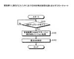
次に、図8を用いて、実施例1に係るFCスイッチにおけるMIB更新処理の流れを説明する。図8に示すように、MIBバージョン受信部22は、管理装置1が管理するFCスイッチ10のMIBが変更されたことを示す変更情報として、管理装置1が管理するFCスイッチ10のMIBのバージョン情報を管理装置1から受信する(ステップS301)。(MIB update process flow)
Next, the flow of MIB update processing in the FC switch according to the first embodiment will be described with reference to FIG. As shown in FIG. 8, the MIB
続いて、優先MIB特定部23は、受信されたMIBのバージョン情報が現時点での優先MIB情報のバージョンと一致するか否かを判定する(ステップS302)。そして、優先MIB特定部23は、受信されたMIBのバージョン情報が現時点での優先MIB情報のバージョンと一致する場合には(ステップS302肯定)、優先MIBの変更を行わずに処理をMIB変更処理終了する。 Subsequently, the priority
一方、優先MIB特定部23は、現時点での優先MIB情報のバージョンと一致しない場合に(ステップS302否定)、受信されたMIBのバージョン情報と一致するMIB情報がMIB蓄積DB16に記憶されているか否かを判定する(ステップS303)。 On the other hand, when the priority
そして、優先MIB特定部23は、受信されたMIBのバージョン情報と一致するMIB情報がMIB蓄積DB16に記憶されている場合には(ステップS303肯定)、一致するMIB情報を新たな優先MIB情報とするmod処理を実行する(ステップS304)。 When the MIB information that matches the received MIB version information is stored in the MIB storage DB 16 (Yes in step S303), the priority
一方、優先MIB特定部23は、受信されたMIBのバージョン情報と一致するMIB情報がMIB蓄積DB16に記憶されていない場合には(ステップS303否定)、管理装置1が管理するMIB情報がFCスイッチ10内に存在しないと判定する。そして、優先MIB特定部23は、エラーを示すアラーム等を管理装置1等に出力するエラー処理を実行する(ステップS305)。以後、更新された優先MIB情報を用いて、図6や図7の処理が実行される。 On the other hand, if the MIB information that matches the received MIB version information is not stored in the MIB accumulation DB 16 (No at step S303), the priority
[実施例1による効果]
このように、実施例1によれば、SNMPエージェント側のMIB情報が変更されてから当該変更に伴ってSNMPマネージャ側のMIB情報が変更されるまでの間も、SNMPによる監視および管理を正確に実施することが可能である。[Effects of Example 1]
As described above, according to the first embodiment, monitoring and management by SNMP are accurately performed from the time when the MIB information on the SNMP agent side is changed to the time when the MIB information on the SNMP manager side is changed in accordance with the change. It is possible to implement.
また、ファームアップを行った際に機能アップをしても、SNMPマネージャのサポート状況を取得することで、MIB送信時に対応した障害情報を送信することができる。SNMPマネージャの管理するMIBが変更された場合でも、それに対応するMIBを障害情報として送信することができる。さらに、MIBログDB17にて、本来のバージョンで送信する障害情報と実際に送信した障害情報を管理し、障害発生時の解析に利用可能とする。また、MIBログDB17において過去のMIB情報も可能な限り保持することで、SNMPマネージャの対応MIBのダウングレードにも対応することができる。 Further, even if the function is improved when the firmware is upgraded, the failure information corresponding to the MIB transmission can be transmitted by acquiring the support status of the SNMP manager. Even when the MIB managed by the SNMP manager is changed, the corresponding MIB can be transmitted as failure information. Further, the
ところで、本願の開示するFCスイッチは、カスケード接続により複数台のFCスイッチを接続することができる。そこで、実施例2では、カスケード接続されたFCスイッチにおいて優先MIBを特定する例について説明する。なお、実施例2では、2台のFCスイッチがカスケード接続される例について説明するが、接続台数を限定するものではない。 By the way, the FC switch disclosed in the present application can connect a plurality of FC switches by cascade connection. Therefore, in the second embodiment, an example in which the priority MIB is specified in the cascade-connected FC switches will be described. In the second embodiment, an example in which two FC switches are cascade-connected will be described, but the number of connected devices is not limited.
(全体構成)
まず、図9を用いて、カスケード接続されたFCスイッチの例を説明する。図9は、実施例2に係るカスケード接続されたFCスイッチの例を示す図である。図9に示すように、FCスイッチ10とFCスイッチ30とがカスケード接続されており、FCスイッチ10と管理装置1とがネットワークで接続されている。(overall structure)
First, an example of cascade-connected FC switches will be described with reference to FIG. FIG. 9 is a diagram illustrating an example of cascade-connected FC switches according to the second embodiment. As shown in FIG. 9, the
FCスイッチ10の構成は、実施例1で説明した構成と同様の構成を有する。また、FCスイッチ30の構成についても、実施例1で説明したFCスイッチ10と同様の構成を有する。具体的には、FCスイッチ30のLANポート31とFCポート32a〜32nと制御回路33それぞれは、FCスイッチ10のLANポート11とFCポート12a〜12nと制御回路13のそれぞれと同様の機能を有する。また、FCスイッチ30のメモリ34と記憶部35と制御部40のそれぞれは、FCスイッチ10のメモリ14と記憶部15と制御部20のそれぞれと同様の機能を有する。 The configuration of the
ただし、FCスイッチ10のMIB蓄積DB16には、FCスイッチ10に対応したMIB情報が記憶されており、FCスイッチ30のMIB蓄積DB36には、FCスイッチ30に対応したMIB情報が記憶されている。すなわち、それぞれのFCスイッチは、自装置の制御部、言い換えると、自装置が有するソフトウエアやファームウェアに対応したMIB情報を記憶している。 However, MIB information corresponding to the
具体的には、FCスイッチ10のMIB蓄積DB16は、FCスイッチ10のMIB情報として、旧MIB情報(A)16aと新MIB情報(A)16bとを記憶する。また、FCスイッチ30のMIB蓄積DB36は、FCスイッチ30のMIB情報として、旧MIB情報(B)36aと新MIB情報(B)36bとを記憶する。 Specifically, the
(処理の流れ)
次に、図10を用いて、図9に示したカスケード接続されるFCスイッチにおけるMIB特定処理の流れを説明する。図10は、実施例2に係るFCスイッチにおけるMIB特定処理の流れを示すフローチャートである。(Process flow)
Next, the flow of MIB specifying processing in the cascade-connected FC switch shown in FIG. 9 will be described with reference to FIG. FIG. 10 is a flowchart illustrating the flow of the MIB specifying process in the FC switch according to the second embodiment.
図10に示すように、FCスイッチ10またはFCスイッチ30のMIB蓄積DBがアップロードされた場合(ステップS401肯定)、FCスイッチ10のMIBバージョン受信部22は、ステップS402の処理を実行する。具体的には、FCスイッチ10のMIBバージョン受信部22は、SNMPマネージャ側である管理装置1が管理するMIBのバージョン情報を取得する。 As shown in FIG. 10, when the MIB accumulation DB of the
続いて、FCスイッチ10の優先MIB特定部23は、MIBバージョン受信部22により取得されたMIBのバージョン情報が自装置のMIB蓄積DB16に記憶されるMIB情報と一致するか否かを判定する(ステップS403)。 Subsequently, the priority
そして、FCスイッチ10の優先MIB特定部23は、自装置のMIB蓄積DB16に記憶されるMIB情報と一致する場合(ステップS403肯定)、受信したバージョンと一致するMIB情報を優先MIB情報と特定する(ステップS404)。 When the priority
一方、FCスイッチ10の優先MIB特定部23は、自装置のMIB蓄積DB16に記憶されるMIB情報と一致しない場合(ステップS403否定)、ステップS405の処理を実行する。具体的には、FCスイッチ10の優先MIB特定部23は、カスケード先のFCスイッチ30のMIB蓄積DB36に記憶されるMIB情報のうち、受信したバージョンと一致するMIB情報を優先MIB情報と特定する。 On the other hand, when the priority
その後、SNMPエージェント制御部24は、優先MIB特定部23によって特定されたFCスイッチ30のMIB情報をカスケード経由で取得し、取得したFCスイッチ30のMIB情報を用いて障害情報を管理装置1に送信する。また、FCスイッチ10は、管理装置1からMIBの変更情報を受信し、当該変更情報がカスケード先のFCスイッチ30のMIB情報と一致する場合には、図10と同様、カスケード先のMIB情報を優先MIB情報と決定する。一方、FCスイッチ10は、変更情報が自装置のMIB情報と一致する場合には、自装置のMIB情報を優先MIB情報と決定する。 Thereafter, the SNMP
(実施例2による効果)
このように、実施例2によれば、FCスイッチ10は、自装置のMIB情報とカスケード先のFCスイッチ30のMIB情報の両方を記憶しなくても、管理装置1に障害情報であるMIB情報を送信することができる。その結果、FCスイッチ内で連携してMIB情報を一元管理することで、MIB蓄積DBに記憶されるMIB情報の重複をなくすることができる。(Effects of Example 2)
As described above, according to the second embodiment, the
また、FCスイッチ10は、障害が検知されるたびに、カスケード経由でMIB情報を取得することを回避するために、例えば、優先MIB情報と特定されたカスケード先のFCスイッチ30に記憶されるMIB情報を自装置の記憶部15に格納しておいてもよい。この結果、FCスイッチ10は、障害が検知されるたびに、カスケード経由でMIB情報を取得することを回避でき、障害情報を迅速に通知することができる。 In addition, the FC switch 10 stores, for example, the MIB stored in the
ところで、実施例2では、カスケード接続される2台のFCスイッチの一方が管理装置1と接続される例について説明したが、これに限定されるものではない。例えば、カスケード接続される2台のFCスイッチそれぞれが管理装置1と接続されている状態で、一方のみがSNMPによる障害通知を行うこともできる。 In the second embodiment, an example in which one of the two FC switches connected in cascade is connected to the management apparatus 1 has been described. However, the present invention is not limited to this. For example, in a state where two cascaded FC switches are connected to the management apparatus 1, only one of them can perform a failure notification by SNMP.
そこで、実施例3では、図11を用いて、カスケード接続される2台のFCスイッチの両方が管理装置1に接続される例について説明する。図11は、実施例3に係るカスケード接続されたFCスイッチの例を示す図である。図11に示すように、実施例3と同様、FCスイッチ10とFCスイッチ30とがカスケード接続されており、FCスイッチ10と管理装置1とがネットワークで接続されている。また、FCスイッチ10の構成は、実施例2で説明したFCスイッチ10と同様であり、FCスイッチ30の構成も実施例2で説明したFCスイッチ30と同様である。ただし、実施例3とは異なり、FCスイッチ10のカスケード先であるFCスイッチ30も管理装置1と接続される。 Therefore, in the third embodiment, an example in which both of the two FC switches connected in cascade are connected to the management apparatus 1 will be described with reference to FIG. FIG. 11 is a diagram illustrating an example of cascade-connected FC switches according to the third embodiment. As shown in FIG. 11, as in the third embodiment, the
このような状態において、実施例1や実施例2で説明したMIB特定処理、MIB通知処理、優先MIB更新処理は、FCスイッチ10の各制御部が実行する。このような状態において、FCスイッチ10のSNMPエージェント制御部24によって、FCスイッチ10と管理装置1との通信切断が検出されたとする。この場合、FCスイッチ10のSNMPエージェント制御部24は、カスケード先のFCスイッチ30の各制御部に対して、SNMPによる障害情報(OID)の通知処理の代行を依頼する。この依頼を受けたFCスイッチ30の制御部40は、FCスイッチ10に代わって、障害情報の通知を実行する。 In such a state, each control unit of the
この際、FCスイッチ30は、FCスイッチ10の各制御部が実行していた処理を全て代行することもでき、例えばSNMPエージェント制御部24のみを代行するなど、特定の制御部のみを代行することもできる。また、FCスイッチ30は、FCスイッチ10から通信が復旧したことが通知された場合には、任意の設定によって、代行していた処理を停止することもでき、そのまま代行し続けることもできる。 At this time, the
このように、実施例3によれば、通常、単一のLANポートが有しないFCスイッチに通信障害が発生した場合であっても、カスケード先のFCスイッチ経由で、障害通知などの処理を実行することができ、システム全体の安定性が向上する。 As described above, according to the third embodiment, even when a communication failure occurs in an FC switch that does not have a single LAN port, processing such as failure notification is performed via the cascaded FC switch. Can improve the stability of the entire system.
ところで、実施例1〜3では、FCスイッチが1台の管理装置と接続される例について説明したが、これに限定されるものではない。本願の開示するFCスイッチは、複数の管理装置に接続されている場合であっても、それぞれの管理装置に適した優先MIB情報を特定して、管理装置各々が管理するMIB情報を用いて障害通知を実施することができる。 In the first to third embodiments, the example in which the FC switch is connected to one management apparatus has been described. However, the present invention is not limited to this. Even when the FC switch disclosed in the present application is connected to a plurality of management devices, it specifies priority MIB information suitable for each management device, and uses the MIB information managed by each management device for failure. Notification can be implemented.
そこで、実施例4では、図12〜図15を用いて、FCスイッチが、複数の管理装置に接続されている場合に、それぞれの管理装置に適した優先MIB情報を特定して、管理装置各々が管理するMIB情報を用いて障害通知を実施する例について説明する。なお、実施例4では、カスケード接続されたFCスイッチを例にして説明するが、実施例1で説明したカスケード接続されていない1台のFCスイッチであっても、同様に処理することができる。 Therefore, in the fourth embodiment, when the FC switch is connected to a plurality of management devices, priority MIB information suitable for each management device is identified and each management device is used, with reference to FIGS. An example in which failure notification is performed using MIB information managed by the client will be described. In the fourth embodiment, the cascade-connected FC switches will be described as an example. However, even one FC switch that is not cascade-connected as described in the first embodiment can be processed in the same manner.
(全体構成)
図12は、実施例4に係るカスケード接続されたFCスイッチの例を示す図である。図12に示すように、FCスイッチ10とFCスイッチ30とがカスケード接続されており、FCスイッチ10がハブ3などのネットワーク機器を介して、管理装置1と管理装置2とのそれぞれに接続されている。(overall structure)
FIG. 12 is a diagram illustrating an example of cascade-connected FC switches according to the fourth embodiment. As shown in FIG. 12, the
FCスイッチ10の構成は、実施例1や2で説明した構成と同様の構成を有する。また、FCスイッチ30の構成についても、実施例1や2で説明したFCスイッチ10と同様の構成を有する。また、管理装置1と管理装置2も同様にSNMPマネージャとして機能を有するが、自装置内で管理するFCスイッチのMIB情報は必ずしも一致しない。 The configuration of the
(処理の流れ)
次に、図13〜図15を用いて、実施例4に係るカスケード接続されたFCスイッチにおける処理の流れを説明する。図13は、実施例4に係るFCスイッチにおけるMIB特定処理の流れを示すフローチャートである。図14は、実施例4に係るFCスイッチにおけるMIB通知処理の流れを示すフローチャートである。図15は、実施例4に係るFCスイッチにおける優先MIB更新処理の流れを示すフローチャートである。(Process flow)
Next, the flow of processing in cascaded FC switches according to the fourth embodiment will be described with reference to FIGS. FIG. 13 is a flowchart illustrating the flow of the MIB specifying process in the FC switch according to the fourth embodiment. FIG. 14 is a flowchart illustrating the flow of the MIB notification process in the FC switch according to the fourth embodiment. FIG. 15 is a flowchart illustrating a flow of priority MIB update processing in the FC switch according to the fourth embodiment.
(MIB特定処理の流れ)
図13に示すように、制御部20等のバージョンアップに伴ってMIB蓄積DB16のMIB情報がアップロードされると(ステップS501肯定)、FCスイッチ10は、ステップS502を実行する。(MIB specific processing flow)
As shown in FIG. 13, when the MIB information of the
具体的には、FCスイッチ10のMIBバージョン受信部22は、SNMPマネージャ側である管理装置1および管理装置2各々から、各々の管理装置が管理する当該FCスイッチ10又はカスケード先のFCスイッチ30のMIBのバージョン情報を取得する。そして、MIBバージョン受信部22は、取得したMIBのバージョン情報を優先MIB特定部23に出力する。 Specifically, the MIB
続いて、FCスイッチ10の優先MIB特定部23は、MIBバージョン受信部22により取得されたMIBのバージョン情報に基づいて、ステップS503の処理を実行する。具体的には、優先MIB特定部23は、MIB蓄積DB16に記憶されるMIB情報またはカスケード先のFCスイッチ30のMIB蓄積DBに記憶されるMIB情報から、取得された取得されたMIBのバージョン情報各々と一致する情報を各々特定する。 Subsequently, the priority
例えば、優先MIB特定部23は、管理装置1から取得したバージョン情報と一致する情報が「旧MIB情報(A)」であり、管理装置2から取得したバージョン情報と一致する情報が「新MIB情報(B)」であるなどと特定する。そして、優先MIB特定部23は、特定したそれぞれのMIB情報を管理装置ごとの優先MIB情報と決定する。このとき、優先MIB特定部23は、特定した優先MIB情報がどの管理装置に対応するものなのかを把握するために、例えば管理装置のIP(Internet Protocol)アドレスやSNMPのコミュニティ名などを優先MIB情報と対応付けてメモリ14等に記憶させておく。 For example, the priority
(MIB通知処理の流れ)
次に、図14を用いて、実施例4に係るFCスイッチにおけるMIB通知処理の流れを説明する。図14に示すように、FCスイッチ10のSNMPエージェント制御部24は、FCスイッチ10に障害が発生したことを検知すると(ステップS601肯定)、ステップS602の処理を実行する。(MIB notification process flow)
Next, the flow of the MIB notification process in the FC switch according to the fourth embodiment will be described with reference to FIG. As illustrated in FIG. 14, when the SNMP
具体的には、SNMPエージェント制御部24は、優先MIB特定部23に対して各管理装置1(各マネージャ)に対応した優先MIB情報の取得を実施するget処理を実行する。 Specifically, the SNMP
続いて、優先MIB特定部23は、SNMPエージェント制御部24からの要求に対する応答として、各管理装置に対応した優先MIB情報をSNMPエージェント制御部24に送信するreply処理を実行する(ステップS603)。 Subsequently, as a response to the request from the SNMP
そして、SNMPエージェント制御部24は、優先MIB特定部23によって特定される優先MIB情報各々を用いて、検知した障害を示す障害情報(OID)を管理装置各々に送信するsend処理を実行する(ステップS604)。 Then, the SNMP
その後、MIBログ生成部25は、SNMPエージェント制御部24によってMIB情報が管理装置各々に送信された場合に、送信された情報や障害情報等をMIBログDB17に格納するwrite処理を実行する(ステップS605)。 After that, when the MIB information is transmitted to each management device by the SNMP
(MIB更新処理の流れ)
次に、図15を用いて、実施例4に係るFCスイッチにおけるMIB更新処理の流れを説明する。図15に示すように、MIBバージョン受信部22は、管理装置が管理するFCスイッチ10のMIBが変更されたことを示す変更情報として、管理装置が管理するFCスイッチ10のMIBのバージョン情報を管理装置から受信する(ステップS701)。(MIB update process flow)
Next, the flow of MIB update processing in the FC switch according to the fourth embodiment will be described with reference to FIG. As shown in FIG. 15, the MIB
続いて、優先MIB特定部23は、複数の管理装置のうちどの管理装置から受信したものかを特定し(ステップS702)、特定した管理装置に対応する優先MIB情報をIPアドレスやSNMPのコミュニティ名等から特定する(ステップS703)。 Subsequently, the priority
その後、優先MIB特定部23は、受信されたMIBのバージョン情報が現時点での優先MIB情報のバージョンと一致するか否かを判定する(ステップS704)。そして、優先MIB特定部23は、受信されたMIBのバージョン情報が現時点での優先MIB情報のバージョンと一致する場合には(ステップS704肯定)、優先MIBの変更を行わずに処理をMIB変更処理終了する。 Thereafter, the priority
一方、優先MIB特定部23は、優先MIB情報のバージョンと一致しない場合に(ステップS704否定)、受信されたMIBのバージョン情報と一致するMIB情報がFCスイッチ10又は30に記憶されているか否かを判定する(ステップS705)。 On the other hand, when the priority
そして、優先MIB特定部23は、受信されたMIBのバージョン情報と一致するMIB情報が記憶されている場合には(ステップS705肯定)、一致するMIB情報を新たな優先MIB情報とするmod処理を実行する(ステップS706)。 When the MIB information that matches the received MIB version information is stored (Yes in step S705), the priority
一方、優先MIB特定部23は、受信されたMIBのバージョン情報と一致するMIB情報が記憶されていない場合には(ステップS705否定)、管理装置が管理するMIB情報がFCスイッチ10または30内に存在しないと判定する。そして、優先MIB特定部23は、エラーを示すアラーム等を管理装置等に出力するエラー処理を実行する(ステップS707)。以後、更新された優先MIB情報を用いて、図6や図7の処理が実行される。 On the other hand, when MIB information that matches the received MIB version information is not stored (No in step S705), the priority
(実施例4による効果)
このように、実施例4によれば、複数の管理装置と接続される場合であっても、管理装置それぞれのMIB更新情報にあわせてMIB情報を通知することができる。この結果、SNMPエージェント側のMIB情報が変更されてから当該変更に伴ってSNMPマネージャ側のMIB情報が変更されるまでの間も、SNMPによる監視および管理を正確に実施することが可能である。(Effects of Example 4)
As described above, according to the fourth embodiment, even when a plurality of management apparatuses are connected, MIB information can be notified in accordance with the MIB update information of each management apparatus. As a result, it is possible to accurately perform monitoring and management by SNMP from the change of the MIB information on the SNMP agent side to the change of the MIB information on the SNMP manager side accompanying the change.
さて、これまで本発明の実施例について説明したが、本発明は上述した実施例以外にも、種々の異なる形態にて実施されてよいものである。そこで、以下に異なる実施例を説明する。 Although the embodiments of the present invention have been described so far, the present invention may be implemented in various different forms other than the embodiments described above. Therefore, different embodiments will be described below.
(対象装置)
実施例1〜4では、FCスイッチを例にして説明したが、本願の開示するスイッチング装置はこれに限定されるものではない。例えば、ファブリックスイッチ、ルータ、L3スイッチ、スイッチングハブなどのネットワーク機器やサーバなどの情報処理装置に対しても、同様に実行することができる。(Target device)
In the first to fourth embodiments, the FC switch has been described as an example. However, the switching device disclosed in the present application is not limited to this. For example, the processing can be similarly performed on network devices such as fabric switches, routers, L3 switches, and switching hubs and information processing apparatuses such as servers.
(MIB情報のマイグレーション)
実施例2〜4で説明したカスケード接続されるFCスイッチでは、FCの結線障害で送信対象MIB情報にアクセス付加とならないために、MIB情報のマイグレーションを実施し、MIB情報を最適な場所に記憶させることができる。なお、カスケードされる台数は、実施例2〜4に記載した2台に限定されるものではなく、複数の台数をカスケード接続することができる。(Migration of MIB information)
In the cascade-connected FC switches described in the second to fourth embodiments, the MIB information is migrated and the MIB information is stored in an optimal location in order not to add access to the transmission target MIB information due to the FC connection failure. be able to. Note that the number of cascaded units is not limited to the two units described in the embodiments 2 to 4, and a plurality of units can be cascade-connected.
例えば、複数のFCスイッチがカスケード接続されている場合には、管理装置と接続されているFCスイッチの近くのFCスイッチに優先MIB情報を記憶させる。また、カスケードしているFC結線が冗長化されているFCスイッチに優先MIB情報を記憶させる。また、FCスイッチ間のホップ数が短くなるように、優先MIB情報を記憶させる。このようにすることで、MIB情報の最適配置を行いファブリック内のMIB蓄積DBへのアクセス不可を発生させないようにすることができる。 For example, when a plurality of FC switches are cascade-connected, the priority MIB information is stored in an FC switch near the FC switch connected to the management apparatus. Further, the priority MIB information is stored in the FC switch in which the cascaded FC connection is made redundant. Also, priority MIB information is stored so that the number of hops between FC switches is shortened. By doing so, it is possible to optimally arrange the MIB information so as not to cause inaccessibility to the MIB accumulation DB in the fabric.
また、FCスイッチは、MIB蓄積DBの格納可能な容量の範囲内で、更新される前の過去のMIB情報を複数記憶し、容量を超える場合に、古い情報から削除するようにしてもよい。この結果、FCスイッチは、数世代分のMIB情報を効率よく記憶することができ、管理装置側のダウングレードにも対応することができる。 Further, the FC switch may store a plurality of past MIB information before being updated within the range of the capacity that can be stored in the MIB accumulation DB, and may delete old information when the capacity is exceeded. As a result, the FC switch can efficiently store several generations of MIB information and can cope with downgrade on the management apparatus side.
(システム)
また、本実施例において説明した各処理のうち、自動的におこなわれるものとして説明した処理の全部または一部を手動的におこなうこともできる。あるいは、手動的におこなわれるものとして説明した処理の全部または一部を公知の方法で自動的におこなうこともできる。この他、上記文書中や図面中で示した処理手順、制御手順、具体的名称、例えば図2等に示した各種のデータやパラメータを含む情については、特記する場合を除いて任意に変更することができる。(system)
In addition, among the processes described in the present embodiment, all or a part of the processes described as being automatically performed can be manually performed. Alternatively, all or part of the processing described as being performed manually can be automatically performed by a known method. In addition, the processing procedures, control procedures, and specific names shown in the above-mentioned documents and drawings, for example, information including various data and parameters shown in FIG. 2 and the like are arbitrarily changed unless otherwise specified. be able to.
また、図示した各装置の各構成要素は機能概念的なものであり、必ずしも物理的に図示の如く構成されていることを要しない。すなわち、例えばMIBバージョン受信部22と優先MIB特定部23とを統合するなど各装置の分散・統合の具体的形態は図示のものに限られない。例えば、その全部または一部を、各種の負荷や使用状況などに応じて、任意の単位で機能的または物理的に分散・統合して構成することができる。さらに、各装置にて行なわれる各処理機能は、その全部または任意の一部が、CPUおよび当該CPUにて解析実行されるプログラムにて実現され、あるいは、ワイヤードロジックによるハードウェアとして実現され得る。 Further, each component of each illustrated apparatus is functionally conceptual, and does not necessarily need to be physically configured as illustrated. That is, the specific form of distribution / integration of each device, for example, integrating the MIB
(プログラム)
ところで、上記の実施例で説明した各種の処理は、あらかじめ用意されたプログラムをパーソナルコンピュータやワークステーションなどのコンピュータシステムで実行することによって実現することができる。そこで、以下では、上記の実施例と同様の機能を有するプログラムを実行するコンピュータシステムの一例を説明する。(program)
By the way, the various processes described in the above embodiments can be realized by executing a program prepared in advance on a computer system such as a personal computer or a workstation. Therefore, in the following, an example of a computer system that executes a program having the same function as in the above embodiment will be described.
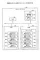
図16は、障害通知制御プログラムを実行するコンピュータシステム100を示す図である。図16に示すように、コンピュータシステム100は、RAM101と、HDD102と、ROM103と、CPU104とを有する。ここで、ROM103には、上の実施例と同様の機能を発揮するプログラムを有するファームウェアがあらかじめ記憶されている。つまり、図16に示すように、スイッチング制御プログラム103a、MIBバージョン受信プログラム103b、優先MIB特定プログラム103c、SNMPエージェント制御プログラム103d、MIBログ生成プログラム103eがあらかじめ記憶されている。 FIG. 16 is a diagram illustrating a
そして、CPU104には、ファームウェアが有するこれらのプログラム103a〜103eを読み出して実行することで、図16に示すように、各プロセスとなる。つまり、スイッチング制御プロセス104a、MIBバージョン受信プロセス104b、優先MIB特定プロセス104c、SNMPエージェント制御プロセス104d、MIBログ生成プロセス104eとなる。なお、スイッチング制御プロセス104aは、図2に示したスイッチング制御部21に対応し、同様に、MIBバージョン受信プロセス104bは、MIBバージョン受信部22に対応する。また、優先MIB特定プロセス104cは、優先MIB特定部23に対応し、SNMPエージェント制御プロセス104dは、SNMPエージェント制御部24に対応する。また、MIBログ生成プロセス104eは、MIBログ生成部25に対応する。 Then, the
また、HDD102には、MIB蓄積テーブル102aとMIBログテーブル102bとを有する。MIB蓄積テーブル102aは、図2に示したMIB蓄積DB16に対応し、同様に、MIBログテーブル102bは、MIBログDB17に対応する。 Further, the
ところで、上記したプログラム103a〜103eは、必ずしもROM103に記憶させておく必要はない。例えば、コンピュータシステム100に挿入されるフレキシブルディスク(FD)、CD−ROM、DVDディスク、光磁気ディスク、ICカードなどの「可搬用の物理媒体」に記憶させておくにしてもよい。また、コンピュータシステム100の内外に備えられるハードディスクドライブ(HDD)などの「固定用の物理媒体」に記憶させておいてもよい。さらに、公衆回線、インターネット、LAN、WANなどを介してコンピュータシステム100に接続される「他のコンピュータシステム」に記憶させておいてもよい。そして、コンピュータシステム100がこれらからプログラムを読み出して実行するようにしてもよい。 By the way, the above-described
すなわち、この他の実施例でいうプログラムは、上記した「可搬用の物理媒体」、「固定用の物理媒体」、「通信媒体」などの記録媒体に、コンピュータ読み取り可能に記録されるものである。そして、コンピュータシステム100は、このような記録媒体からプログラムを読み出して実行することで上記した実施例と同様の機能を実現する。なお、この他の実施例でいうプログラムは、コンピュータシステム100によって実行されることに限定されるものではない。例えば、他のコンピュータシステムまたはサーバがプログラムを実行する場合や、これらが協働してプログラムを実行するような場合にも、本発明を同様に適用することができる。 That is, the program referred to in the other embodiments is recorded in a computer-readable manner on a recording medium such as the above-mentioned “portable physical medium”, “fixed physical medium”, “communication medium”, and the like. . Then, the
以上の各実施例を含む実施形態に関し、さらに以下の付記を開示する。 The following supplementary notes are further disclosed with respect to the embodiments including the above examples.
(付記1)更新された管理情報を示す更新後管理情報と更新される前の管理情報を示す更新前管理情報とを記憶する管理情報記憶部と、
障害監視対象装置で発生した障害を管理する管理装置が記憶する管理情報を特定する情報を取得し、取得された情報に基づいて、前記管理情報記憶部に記憶される管理情報のうち前記管理装置が記憶する管理情報を特定する管理情報特定部と、
障害を検知した場合に、前記管理情報特定部によって特定された管理情報に基づいて、障害情報を前記管理装置に送信する情報送信部と
を有することを特徴とするスイッチング装置。(Supplementary Note 1) a management information storage unit that stores post-update management information indicating updated management information and pre-update management information indicating management information before being updated;
Information for specifying management information stored in a management device that manages a failure that has occurred in a failure monitoring target device is acquired, and the management device among the management information stored in the management information storage unit based on the acquired information A management information specifying unit for specifying management information stored by
An information transmission unit that transmits failure information to the management device based on the management information specified by the management information specifying unit when a failure is detected.
(付記2)前記管理情報特定部は、前記管理情報記憶部に更新後管理情報が格納された場合に、前記管理装置が記憶する管理情報を特定する情報を取得して、前記管理情報記憶部に記憶される管理情報のうち前記管理装置が記憶する管理情報を特定することを特徴とする付記1に記載のスイッチング装置。(Supplementary note 2) When the management information storage unit stores updated management information, the management information specifying unit acquires information specifying management information stored in the management device, and the management information storage unit The switching apparatus according to claim 1, wherein management information stored in the management apparatus is specified from among the management information stored in the management apparatus.
(付記3)前記管理情報特定部は、前記管理装置が記憶する管理情報が更新された場合に、前記管理装置が記憶する管理情報を特定する情報を取得して、前記管理情報記憶部に記憶される管理情報のうち前記管理装置が記憶する管理情報を特定することを特徴とする付記1に記載のスイッチング装置。(Additional remark 3) When the management information which the said management apparatus memorize | stores is updated, the said management information specific | specification part acquires the information which identifies the management information which the said management apparatus memorize | stores, and memorize | stores in the said management information storage part The switching apparatus according to appendix 1, wherein management information stored in the management apparatus is specified among management information to be stored.
(付記4)前記管理情報特定部は、前記特定される管理情報が自装置とカスケード接続されるスイッチング装置に格納されている場合には、当該カスケード先のスイッチング装置に格納される管理情報を前記管理装置が記憶する管理情報と特定し、
前記情報送信部は、障害を検知した場合に、前記管理情報特定部によって特定されたカスケード先のスイッチング装置に記憶される管理情報を取得し、取得した管理情報に基づいて、障害情報を前記管理装置に送信することを特徴とする付記1に記載のスイッチング装置。(Additional remark 4) When the management information specified by the management information is stored in a switching device cascade-connected to the own device, the management information specifying unit stores the management information stored in the switching device of the cascade destination Identify the management information stored in the management device,
When the information transmission unit detects a failure, the information transmission unit acquires management information stored in the cascade destination switching device specified by the management information specifying unit, and manages the failure information based on the acquired management information. The switching apparatus according to appendix 1, wherein the switching apparatus transmits the apparatus to the apparatus.
(付記5)前記管理情報特定部は、前記カスケード先のスイッチング装置に格納される管理情報を前記管理装置が記憶する管理情報と特定した場合には、特定したカスケード先の管理情報を前記管理情報記憶部に格納し、
前記情報送信部は、障害を検知した場合に、前記管理情報記憶部に格納されるカスケード先のスイッチング装置に記憶されていた管理情報に基づいて、障害情報を前記管理装置に送信することを特徴とする付記4に記載のスイッチング装置。(Supplementary Note 5) When the management information identifying unit identifies the management information stored in the cascade destination switching device as the management information stored in the management device, the management information identifying unit identifies the management information identified in the cascade destination as the management information. Stored in the storage unit,
The information transmission unit, when detecting a failure, transmits the failure information to the management device based on the management information stored in the cascade destination switching device stored in the management information storage unit. The switching device according to appendix 4.
(付記6)前記情報送信部は、自装置と管理装置との間の通信が切断された場合には、自装置とカスケード接続されるスイッチング装置を介して、前記障害情報を管理装置に送信することを特徴とする付記1に記載のスイッチング装置。(Supplementary Note 6) When the communication between the own device and the management device is disconnected, the information transmission unit transmits the failure information to the management device via the switching device cascade-connected to the own device. 2. The switching device according to appendix 1, wherein
(付記7)前記管理情報特定部は、複数の管理装置各々から管理情報を特定する情報を取得した場合、取得された管理装置ごとの管理情報を特定する情報に基づいて、前記管理装置各々が管理する管理情報を前記管理情報記憶部に記憶される管理情報から特定し、
前記情報送信部は、障害を検知した場合に、前記管理情報特定部によって特定された管理装置ごとの管理情報に基づいて、前記複数の管理装置各々に障害情報を送信することを特徴とする付記1に記載のスイッチング装置。(Additional remark 7) When the said management information specific | specification part acquires the information which specifies management information from each of several management apparatus, each said management apparatus is based on the information which specifies the management information for every acquired management apparatus. Identify management information to be managed from management information stored in the management information storage unit,
The information transmission unit, when detecting a failure, transmits the failure information to each of the plurality of management devices based on management information for each management device specified by the management information specifying unit. 2. The switching device according to 1.
(付記8)更新された管理情報を示す更新後管理情報と更新される前の管理情報を示す更新前管理情報とを記憶する管理情報記憶部と、
障害監視対象装置で発生した障害を管理する管理装置が記憶する管理情報を特定する情報を取得し、取得された管理情報を特定する情報に基づいて、前記管理情報記憶部に記憶される管理情報のうち前記管理装置が記憶する管理情報を特定する管理情報特定部と、
障害を検知した場合に、前記管理情報特定部によって特定された管理情報に基づいて、障害情報を前記管理装置に送信する情報送信部と
を有することを特徴とする情報処理装置。(Supplementary Note 8) A management information storage unit that stores post-update management information indicating updated management information and pre-update management information indicating management information before being updated;
Management information stored in the management information storage unit is acquired based on information specifying management information stored in a management device that manages a failure that has occurred in a failure monitoring target device. A management information specifying unit for specifying management information stored in the management device,
An information processing apparatus comprising: an information transmission unit configured to transmit failure information to the management apparatus based on management information identified by the management information identification unit when a failure is detected.
(付記9)障害監視対象装置で発生した障害を管理する管理装置が記憶する管理情報を特定する情報を取得し、取得された管理情報を特定する情報に基づいて、更新された管理情報を示す更新後管理情報と更新される前の管理情報を示す更新前管理情報とを記憶する管理情報記憶部に記憶される管理情報のうち前記管理装置が記憶する管理情報を特定する管理情報特定手順と、
障害を検知した場合に、前記管理情報特定手順によって特定された管理情報に基づいて、障害情報を前記管理装置に送信する情報送信手順と、
をコンピュータに実行させることを特徴とする障害通知制御プログラム。(Additional remark 9) The information which identifies the management information which the management apparatus which manages the failure which generate | occur | produced in the failure monitoring object apparatus memorize | stores is acquired, and the updated management information is shown based on the information which identifies the acquired management information A management information specifying procedure for specifying management information stored in the management device among management information stored in a management information storage unit for storing post-update management information and pre-update management information indicating management information before being updated; ,
An information transmission procedure for transmitting failure information to the management device based on the management information identified by the management information identification procedure when a failure is detected;
A failure notification control program for causing a computer to execute
1、2 管理装置
3 ハブ
5、6 サーバ
10、30 FCスイッチ
11 LANポート
12a〜12n FCポート
13 制御回路
14 メモリ
15 記憶部
16 MIB蓄積DB
16a 旧MIB情報
16b 新MIB情報
17 MIBログDB
20 制御部
21 スイッチング制御部
22 MIBバージョン受信部
23 優先MIB特定部
24 SNMPエージェント制御部
25 MIBログ生成部DESCRIPTION OF SYMBOLS 1, 2
16a
DESCRIPTION OF
Claims (5)
Translated fromJapanese障害監視対象装置で発生した障害を管理する管理装置が記憶する管理情報を特定する情報を取得し、取得された情報に基づいて、前記管理情報記憶部に記憶される管理情報のうち前記管理装置が記憶する管理情報を特定する管理情報特定部と、
障害を検知した場合に、前記管理情報特定部によって特定された前記最新の管理情報または前記更新される前の管理情報のいずれかの管理情報に基づいて、前記障害によって特定される前記識別子を含む障害情報を前記管理装置に送信する情報送信部と、
前記情報送信部が送信した前記識別子と、前記検知された障害の情報と、前記識別子を送信した時点での前記最新の管理情報を用いて前記検知された障害によって特定される識別子と、を対応付けて所定の記憶部に格納する格納制御部と
を有することを特徴とするスイッチング装置。A management information storage unit for storing thelatest management information including an identifier specified by a failure, and management informationbefore being updated including an identifier specified by the failure;
Information for specifying management information stored in a management device that manages a failure that has occurred in a failure monitoring target device is acquired, and the management device among the management information stored in the management information storage unit based on the acquired information A management information specifying unit for specifying management information stored by
When the failure is detected, the identifier specified by the failure is included based on the management information of either thelatest management information specified by the management information specifying unit or the management informationbefore being updated. An information transmission unit for transmitting failure information to the management device;
Corresponding with the identifier by the information transmitting unit transmits the information of the detected failure, and a identifier specified by the detected fault by usingthe latest management information at the time of sending the identifier And a storage control unit that stores the data in a predetermined storage unit.
前記情報送信部は、障害を検知した場合に、前記管理情報特定部によって特定されたカスケード先のスイッチング装置に記憶される管理情報を取得し、取得した管理情報に基づいて、前記障害情報を前記管理装置に送信することを特徴とする請求項1に記載のスイッチング装置。When the specified management information is stored in a switching device that is cascade-connected to the own device, the management information specifying unit stores the management information stored in the cascade-destination switching device. Management information to identify,
When the information transmission unit detects a failure, the information transmission unit acquires management information stored in the cascade destination switching device specified by the management information specifying unit, and based on the acquired management information, the failure information The switching device according to claim 1, wherein the switching device is transmitted to a management device.
前記情報送信部は、障害を検知した場合に、前記管理情報特定部によって特定された管理装置ごとの管理情報に基づいて、前記複数の管理装置各々に障害情報を送信することを特徴とする請求項1に記載のスイッチング装置。When the management information specifying unit acquires information specifying management information from each of a plurality of management devices, the management information managed by each of the management devices based on the acquired information specifying management information for each management device Is identified from the management information stored in the management information storage unit,
The information transmitting unit, when detecting a failure, transmits the failure information to each of the plurality of management devices based on management information for each management device specified by the management information specifying unit. Item 4. The switching device according to Item 1.
障害監視対象装置で発生した障害を管理する管理装置が記憶する管理情報を特定する情報を取得し、取得された管理情報を特定する情報に基づいて、前記管理情報記憶部に記憶される管理情報のうち前記管理装置が記憶する管理情報を特定する管理情報特定部と、
障害を検知した場合に、前記管理情報特定部によって特定された前記最新の管理情報または前記更新される前の管理情報のいずれかの管理情報に基づいて、前記障害によって特定される前記識別子を含む障害情報を前記管理装置に送信する情報送信部と、
前記情報送信部が送信した前記識別子と、前記検知された障害の情報と、前記識別子を送信した時点での前記最新の管理情報を用いて前記検知された障害によって特定される識別子と、を対応付けて所定の記憶部に格納する格納制御部と
を有することを特徴とする情報処理装置。A management information storage unit for storing thelatest management information including an identifier specified by a failure, and management informationbefore being updated including an identifier specified by the failure;
Management information stored in the management information storage unit is acquired based on information specifying management information stored in a management device that manages a failure that has occurred in a failure monitoring target device. A management information specifying unit for specifying management information stored in the management device,
When the failure is detected, the identifier specified by the failure is included based on the management information of either thelatest management information specified by the management information specifying unit or the management informationbefore being updated. An information transmission unit for transmitting failure information to the management device;
Corresponding with the identifier by the information transmitting unit transmits the information of the detected failure, and a identifier specified by the detected fault by usingthe latest management information at the time of sending the identifier And a storage control unit that stores the information in a predetermined storage unit.
障害を検知した場合に、前記管理情報特定手順によって特定された前記最新の管理情報または前記更新される前の管理情報のいずれかの管理情報に基づいて、前記障害によって特定される前記識別子を含む障害情報を前記管理装置に送信する情報送信手順と、
前記情報送信手順によって送信された前記識別子と、前記検知された障害の情報と、前記識別子を送信した時点での前記最新の管理情報を用いて前記検知された障害によって特定される識別子と、を対応付けて所定の記憶部に格納する格納制御手順と
をコンピュータに実行させることを特徴とする障害通知制御プログラム。Thelatest management including the identifier identified by the failure based on the information identifying the management information acquired by acquiring the management information stored in the management device that manages the failure that occurred in the failure monitoring target device A management information specifying procedure for specifying management information stored in the management device among management information stored in a management information storage unit for storing information and management informationbefore updating including an identifier specified by the failure; ,
When a failure is detected, the identifier identified by the failure is included based on management information of either thelatest management information identified by the management information identification procedure or the management informationbefore being updated. An information transmission procedure for transmitting fault information to the management device;
And the identifier transmitted by the information transmission procedure, and information of the detected failure, and a identifier specified by the detected fault usingsaid latest management information at the time of sending the identifier A failure notification control program that causes a computer to execute a storage control procedure that is stored in a predetermined storage unit in association with each other.
Priority Applications (2)
| Application Number | Priority Date | Filing Date | Title |
|---|---|---|---|
| JP2010073476AJP5617304B2 (en) | 2010-03-26 | 2010-03-26 | Switching device, information processing device, and fault notification control program |
| US13/052,236US8498214B2 (en) | 2010-03-26 | 2011-03-21 | Switching device, information processing device, and recording medium for failure notification control program |
Applications Claiming Priority (1)
| Application Number | Priority Date | Filing Date | Title |
|---|---|---|---|
| JP2010073476AJP5617304B2 (en) | 2010-03-26 | 2010-03-26 | Switching device, information processing device, and fault notification control program |
Publications (2)
| Publication Number | Publication Date |
|---|---|
| JP2011204192A JP2011204192A (en) | 2011-10-13 |
| JP5617304B2true JP5617304B2 (en) | 2014-11-05 |
Family
ID=44657742
Family Applications (1)
| Application Number | Title | Priority Date | Filing Date |
|---|---|---|---|
| JP2010073476AActiveJP5617304B2 (en) | 2010-03-26 | 2010-03-26 | Switching device, information processing device, and fault notification control program |
Country Status (2)
| Country | Link |
|---|---|
| US (1) | US8498214B2 (en) |
| JP (1) | JP5617304B2 (en) |
Families Citing this family (8)
| Publication number | Priority date | Publication date | Assignee | Title |
|---|---|---|---|---|
| US20120265872A1 (en)* | 2011-04-18 | 2012-10-18 | Cox Communications, Inc. | Systems and Methods of Automatically Remediating Fault Conditions |
| CN104734961B (en)* | 2013-12-20 | 2017-10-24 | 中国航空工业集团公司第六三一研究所 | Route selection method based on FC exchange networks |
| US9971840B2 (en)* | 2014-05-07 | 2018-05-15 | Connectwise, Inc. | Systems and methods for discovering and monitoring devices using search patterns for object identifiers and values |
| US10536357B2 (en) | 2015-06-05 | 2020-01-14 | Cisco Technology, Inc. | Late data detection in data center |
| US10142353B2 (en) | 2015-06-05 | 2018-11-27 | Cisco Technology, Inc. | System for monitoring and managing datacenters |
| CN107528723A (en)* | 2017-07-07 | 2017-12-29 | 中国南方电网有限责任公司 | A kind of communication means suitable for power system interchanger |
| US10986213B2 (en)* | 2019-01-30 | 2021-04-20 | GAVS Technologies Pvt. Ltd. | Method and system for streaming management information base data using simple network management protocol |
| JP7362583B2 (en)* | 2020-09-23 | 2023-10-17 | 株式会社東芝 | information processing equipment |
Family Cites Families (9)
| Publication number | Priority date | Publication date | Assignee | Title |
|---|---|---|---|---|
| US6185203B1 (en)* | 1997-02-18 | 2001-02-06 | Vixel Corporation | Fibre channel switching fabric |
| JP3206644B2 (en) | 1997-08-11 | 2001-09-10 | 日本電気株式会社 | Network management method |
| JP2001333072A (en) | 2000-05-19 | 2001-11-30 | Toyo Commun Equip Co Ltd | Snmp network management system and method |
| JP3854852B2 (en)* | 2001-11-09 | 2006-12-06 | パナソニック コミュニケーションズ株式会社 | Management information transmission device, device management device, and device management system |
| JP2005157712A (en)* | 2003-11-26 | 2005-06-16 | Hitachi Ltd | Remote copy network |
| JP2005209056A (en)* | 2004-01-26 | 2005-08-04 | Ricoh Co Ltd | Network device and network device information providing method |
| JP4990089B2 (en)* | 2007-10-12 | 2012-08-01 | 株式会社日立製作所 | Computer system that backs up and restores the encryption key of the storage device with built-in data encryption function |
| JP4480756B2 (en)* | 2007-12-05 | 2010-06-16 | 富士通株式会社 | Storage management device, storage system control device, storage management program, data storage system, and data storage method |
| JP5309715B2 (en)* | 2008-06-19 | 2013-10-09 | 株式会社リコー | Managed device, trap transmission destination setting method, and trap transmission destination setting program |
- 2010
- 2010-03-26JPJP2010073476Apatent/JP5617304B2/enactiveActive
- 2011
- 2011-03-21USUS13/052,236patent/US8498214B2/ennot_activeExpired - Fee Related
Also Published As
| Publication number | Publication date |
|---|---|
| US8498214B2 (en) | 2013-07-30 |
| JP2011204192A (en) | 2011-10-13 |
| US20110239058A1 (en) | 2011-09-29 |
Similar Documents
| Publication | Publication Date | Title |
|---|---|---|
| JP5617304B2 (en) | Switching device, information processing device, and fault notification control program | |
| US9141489B2 (en) | Failover procedure for server system | |
| US10574532B2 (en) | Component detection and management using relationships | |
| US8214823B2 (en) | Cluster system, process for updating software, service provision node, and computer-readable medium storing service provision program | |
| US8909758B2 (en) | Physical server discovery and correlation | |
| CN101981546B (en) | Root cause analysis method targeting information technology (IT) device not to acquire event information, device and program | |
| US9692819B2 (en) | Detect process health remotely in a realtime fashion | |
| JP2004326790A (en) | Method and device for discovering network device | |
| JP5530864B2 (en) | Network system, management server, and management method | |
| US20070070975A1 (en) | Storage system and storage device | |
| CN104301141A (en) | A method, device and system for storing configuration information | |
| WO2013171865A1 (en) | Management method and management system | |
| JP4464256B2 (en) | Network host monitoring device | |
| JP6222759B2 (en) | Failure notification device, failure notification method and program | |
| WO2020010906A1 (en) | Method and device for operating system (os) batch installation, and network device | |
| CN116112500B (en) | NFS high availability system and method based on fault detection and routing strategy | |
| CN112468330A (en) | Method, system, equipment and medium for setting fault node | |
| JP4658901B2 (en) | System and network monitoring method | |
| US9319271B2 (en) | Management device and management method | |
| JP2016200961A (en) | Server failure monitoring system | |
| JP4589939B2 (en) | Connection information management method, apparatus and program | |
| JP2012164134A (en) | Management device, management method, and program | |
| JP2019508975A (en) | Neighbor monitoring in hyperscale environment | |
| JP4790579B2 (en) | Process monitoring apparatus and monitoring method | |
| JP5764090B2 (en) | Terminal state detection apparatus and terminal state detection method |
Legal Events
| Date | Code | Title | Description |
|---|---|---|---|
| A621 | Written request for application examination | Free format text:JAPANESE INTERMEDIATE CODE: A621 Effective date:20130206 | |
| A977 | Report on retrieval | Free format text:JAPANESE INTERMEDIATE CODE: A971007 Effective date:20131028 | |
| A131 | Notification of reasons for refusal | Free format text:JAPANESE INTERMEDIATE CODE: A131 Effective date:20131105 | |
| A521 | Request for written amendment filed | Free format text:JAPANESE INTERMEDIATE CODE: A523 Effective date:20131227 | |
| A131 | Notification of reasons for refusal | Free format text:JAPANESE INTERMEDIATE CODE: A131 Effective date:20140325 | |
| A521 | Request for written amendment filed | Free format text:JAPANESE INTERMEDIATE CODE: A523 Effective date:20140526 | |
| TRDD | Decision of grant or rejection written | ||
| A01 | Written decision to grant a patent or to grant a registration (utility model) | Free format text:JAPANESE INTERMEDIATE CODE: A01 Effective date:20140819 | |
| A61 | First payment of annual fees (during grant procedure) | Free format text:JAPANESE INTERMEDIATE CODE: A61 Effective date:20140901 | |
| R150 | Certificate of patent or registration of utility model | Ref document number:5617304 Country of ref document:JP Free format text:JAPANESE INTERMEDIATE CODE: R150 | |
| S111 | Request for change of ownership or part of ownership | Free format text:JAPANESE INTERMEDIATE CODE: R313111 | |
| R350 | Written notification of registration of transfer | Free format text:JAPANESE INTERMEDIATE CODE: R350 | |
| R250 | Receipt of annual fees | Free format text:JAPANESE INTERMEDIATE CODE: R250 |