JP5616795B2 - Venous filter - Google Patents
Venous filterDownload PDFInfo
- Publication number
- JP5616795B2 JP5616795B2JP2010542254AJP2010542254AJP5616795B2JP 5616795 B2JP5616795 B2JP 5616795B2JP 2010542254 AJP2010542254 AJP 2010542254AJP 2010542254 AJP2010542254 AJP 2010542254AJP 5616795 B2JP5616795 B2JP 5616795B2
- Authority
- JP
- Japan
- Prior art keywords
- filter
- vascular
- region
- struts
- spacer
- Prior art date
- Legal status (The legal status is an assumption and is not a legal conclusion. Google has not performed a legal analysis and makes no representation as to the accuracy of the status listed.)
- Expired - Fee Related
Links
- 230000002792vascularEffects0.000claimsdescription40
- 125000006850spacer groupChemical group0.000claimsdescription33
- 210000004204blood vesselAnatomy0.000claimsdescription20
- 239000002245particleSubstances0.000claimsdescription7
- 239000012781shape memory materialSubstances0.000claimsdescription5
- 238000005520cutting processMethods0.000claimsdescription2
- 208000007536ThrombosisDiseases0.000description9
- 230000017531blood circulationEffects0.000description9
- 238000000034methodMethods0.000description7
- 210000001631vena cava inferiorAnatomy0.000description7
- 238000003780insertionMethods0.000description5
- 230000037431insertionEffects0.000description5
- 210000004072lungAnatomy0.000description5
- 210000003191femoral veinAnatomy0.000description4
- 238000001914filtrationMethods0.000description4
- 210000004731jugular veinAnatomy0.000description4
- 229910001000nickel titaniumInorganic materials0.000description4
- 208000010378Pulmonary EmbolismDiseases0.000description3
- 229910000734martensiteInorganic materials0.000description3
- 238000011084recoveryMethods0.000description3
- 230000007704transitionEffects0.000description3
- FAPWRFPIFSIZLT-UHFFFAOYSA-MSodium chlorideChemical compound[Na+].[Cl-]FAPWRFPIFSIZLT-UHFFFAOYSA-M0.000description2
- 239000003146anticoagulant agentSubstances0.000description2
- 229940127219anticoagulant drugDrugs0.000description2
- 230000004888barrier functionEffects0.000description2
- 230000036760body temperatureEffects0.000description2
- 229940079593drugDrugs0.000description2
- 239000003814drugSubstances0.000description2
- 230000006870functionEffects0.000description2
- 238000003698laser cuttingMethods0.000description2
- 239000000463materialSubstances0.000description2
- HLXZNVUGXRDIFK-UHFFFAOYSA-Nnickel titaniumChemical compound[Ti].[Ti].[Ti].[Ti].[Ti].[Ti].[Ti].[Ti].[Ti].[Ti].[Ti].[Ni].[Ni].[Ni].[Ni].[Ni].[Ni].[Ni].[Ni].[Ni].[Ni].[Ni].[Ni].[Ni].[Ni]HLXZNVUGXRDIFK-UHFFFAOYSA-N0.000description2
- 230000000149penetrating effectEffects0.000description2
- 238000000926separation methodMethods0.000description2
- 239000011780sodium chlorideSubstances0.000description2
- 210000003462veinAnatomy0.000description2
- HTTJABKRGRZYRN-UHFFFAOYSA-NHeparinChemical compoundOC1C(NC(=O)C)C(O)OC(COS(O)(=O)=O)C1OC1C(OS(O)(=O)=O)C(O)C(OC2C(C(OS(O)(=O)=O)C(OC3C(C(O)C(O)C(O3)C(O)=O)OS(O)(=O)=O)C(CO)O2)NS(O)(=O)=O)C(C(O)=O)O1HTTJABKRGRZYRN-UHFFFAOYSA-N0.000description1
- 208000006011StrokeDiseases0.000description1
- 238000004873anchoringMethods0.000description1
- 210000000702aorta abdominalAnatomy0.000description1
- 229910001566austeniteInorganic materials0.000description1
- 230000000740bleeding effectEffects0.000description1
- 239000008280bloodSubstances0.000description1
- 210000004369bloodAnatomy0.000description1
- 239000012267brineSubstances0.000description1
- 230000003247decreasing effectEffects0.000description1
- 238000004090dissolutionMethods0.000description1
- 229910000701elgiloys (Co-Cr-Ni Alloy)Inorganic materials0.000description1
- 230000001747exhibiting effectEffects0.000description1
- 239000011521glassSubstances0.000description1
- 229920000669heparinPolymers0.000description1
- 229960001008heparin sodiumDrugs0.000description1
- 208000014674injuryDiseases0.000description1
- 238000005304joiningMethods0.000description1
- 238000002690local anesthesiaMethods0.000description1
- 210000003141lower extremityAnatomy0.000description1
- 238000004519manufacturing processMethods0.000description1
- 239000007769metal materialSubstances0.000description1
- 230000004048modificationEffects0.000description1
- 238000012986modificationMethods0.000description1
- 238000006213oxygenation reactionMethods0.000description1
- 230000002980postoperative effectEffects0.000description1
- 150000003839saltsChemical class0.000description1
- 229910001285shape-memory alloyInorganic materials0.000description1
- 230000035939shockEffects0.000description1
- KYITYFHKDODNCQ-UHFFFAOYSA-Msodium;2-oxo-3-(3-oxo-1-phenylbutyl)chromen-4-olateChemical compound[Na+].[O-]C=1C2=CC=CC=C2OC(=O)C=1C(CC(=O)C)C1=CC=CC=C1KYITYFHKDODNCQ-UHFFFAOYSA-M0.000description1
- HPALAKNZSZLMCH-UHFFFAOYSA-Msodium;chloride;hydrateChemical compoundO.[Na+].[Cl-]HPALAKNZSZLMCH-UHFFFAOYSA-M0.000description1
- 239000010935stainless steelSubstances0.000description1
- 229910001220stainless steelInorganic materials0.000description1
- 238000001356surgical procedureMethods0.000description1
- 230000008733traumaEffects0.000description1
- 238000011144upstream manufacturingMethods0.000description1
- 210000005166vasculatureAnatomy0.000description1
- 210000002620vena cava superiorAnatomy0.000description1
- 229960002647warfarin sodiumDrugs0.000description1
- XLYOFNOQVPJJNP-UHFFFAOYSA-NwaterSubstancesOXLYOFNOQVPJJNP-UHFFFAOYSA-N0.000description1
Images


Classifications
- A—HUMAN NECESSITIES
- A61—MEDICAL OR VETERINARY SCIENCE; HYGIENE
- A61F—FILTERS IMPLANTABLE INTO BLOOD VESSELS; PROSTHESES; DEVICES PROVIDING PATENCY TO, OR PREVENTING COLLAPSING OF, TUBULAR STRUCTURES OF THE BODY, e.g. STENTS; ORTHOPAEDIC, NURSING OR CONTRACEPTIVE DEVICES; FOMENTATION; TREATMENT OR PROTECTION OF EYES OR EARS; BANDAGES, DRESSINGS OR ABSORBENT PADS; FIRST-AID KITS
- A61F2/00—Filters implantable into blood vessels; Prostheses, i.e. artificial substitutes or replacements for parts of the body; Appliances for connecting them with the body; Devices providing patency to, or preventing collapsing of, tubular structures of the body, e.g. stents
- A61F2/01—Filters implantable into blood vessels
- A61F2/0105—Open ended, i.e. legs gathered only at one side
- A—HUMAN NECESSITIES
- A61—MEDICAL OR VETERINARY SCIENCE; HYGIENE
- A61F—FILTERS IMPLANTABLE INTO BLOOD VESSELS; PROSTHESES; DEVICES PROVIDING PATENCY TO, OR PREVENTING COLLAPSING OF, TUBULAR STRUCTURES OF THE BODY, e.g. STENTS; ORTHOPAEDIC, NURSING OR CONTRACEPTIVE DEVICES; FOMENTATION; TREATMENT OR PROTECTION OF EYES OR EARS; BANDAGES, DRESSINGS OR ABSORBENT PADS; FIRST-AID KITS
- A61F2/00—Filters implantable into blood vessels; Prostheses, i.e. artificial substitutes or replacements for parts of the body; Appliances for connecting them with the body; Devices providing patency to, or preventing collapsing of, tubular structures of the body, e.g. stents
- A61F2/01—Filters implantable into blood vessels
- A61F2002/016—Filters implantable into blood vessels made from wire-like elements
- A—HUMAN NECESSITIES
- A61—MEDICAL OR VETERINARY SCIENCE; HYGIENE
- A61F—FILTERS IMPLANTABLE INTO BLOOD VESSELS; PROSTHESES; DEVICES PROVIDING PATENCY TO, OR PREVENTING COLLAPSING OF, TUBULAR STRUCTURES OF THE BODY, e.g. STENTS; ORTHOPAEDIC, NURSING OR CONTRACEPTIVE DEVICES; FOMENTATION; TREATMENT OR PROTECTION OF EYES OR EARS; BANDAGES, DRESSINGS OR ABSORBENT PADS; FIRST-AID KITS
- A61F2210/00—Particular material properties of prostheses classified in groups A61F2/00 - A61F2/26 or A61F2/82 or A61F9/00 or A61F11/00 or subgroups thereof
- A61F2210/0014—Particular material properties of prostheses classified in groups A61F2/00 - A61F2/26 or A61F2/82 or A61F9/00 or A61F11/00 or subgroups thereof using shape memory or superelastic materials, e.g. nitinol
- A—HUMAN NECESSITIES
- A61—MEDICAL OR VETERINARY SCIENCE; HYGIENE
- A61F—FILTERS IMPLANTABLE INTO BLOOD VESSELS; PROSTHESES; DEVICES PROVIDING PATENCY TO, OR PREVENTING COLLAPSING OF, TUBULAR STRUCTURES OF THE BODY, e.g. STENTS; ORTHOPAEDIC, NURSING OR CONTRACEPTIVE DEVICES; FOMENTATION; TREATMENT OR PROTECTION OF EYES OR EARS; BANDAGES, DRESSINGS OR ABSORBENT PADS; FIRST-AID KITS
- A61F2220/00—Fixations or connections for prostheses classified in groups A61F2/00 - A61F2/26 or A61F2/82 or A61F9/00 or A61F11/00 or subgroups thereof
- A61F2220/0008—Fixation appliances for connecting prostheses to the body
- A61F2220/0016—Fixation appliances for connecting prostheses to the body with sharp anchoring protrusions, e.g. barbs, pins, spikes
- A—HUMAN NECESSITIES
- A61—MEDICAL OR VETERINARY SCIENCE; HYGIENE
- A61F—FILTERS IMPLANTABLE INTO BLOOD VESSELS; PROSTHESES; DEVICES PROVIDING PATENCY TO, OR PREVENTING COLLAPSING OF, TUBULAR STRUCTURES OF THE BODY, e.g. STENTS; ORTHOPAEDIC, NURSING OR CONTRACEPTIVE DEVICES; FOMENTATION; TREATMENT OR PROTECTION OF EYES OR EARS; BANDAGES, DRESSINGS OR ABSORBENT PADS; FIRST-AID KITS
- A61F2230/00—Geometry of prostheses classified in groups A61F2/00 - A61F2/26 or A61F2/82 or A61F9/00 or A61F11/00 or subgroups thereof
- A61F2230/0002—Two-dimensional shapes, e.g. cross-sections
- A61F2230/0028—Shapes in the form of latin or greek characters
- A61F2230/005—Rosette-shaped, e.g. star-shaped
- A—HUMAN NECESSITIES
- A61—MEDICAL OR VETERINARY SCIENCE; HYGIENE
- A61F—FILTERS IMPLANTABLE INTO BLOOD VESSELS; PROSTHESES; DEVICES PROVIDING PATENCY TO, OR PREVENTING COLLAPSING OF, TUBULAR STRUCTURES OF THE BODY, e.g. STENTS; ORTHOPAEDIC, NURSING OR CONTRACEPTIVE DEVICES; FOMENTATION; TREATMENT OR PROTECTION OF EYES OR EARS; BANDAGES, DRESSINGS OR ABSORBENT PADS; FIRST-AID KITS
- A61F2230/00—Geometry of prostheses classified in groups A61F2/00 - A61F2/26 or A61F2/82 or A61F9/00 or A61F11/00 or subgroups thereof
- A61F2230/0063—Three-dimensional shapes
- A61F2230/0067—Three-dimensional shapes conical
- A—HUMAN NECESSITIES
- A61—MEDICAL OR VETERINARY SCIENCE; HYGIENE
- A61F—FILTERS IMPLANTABLE INTO BLOOD VESSELS; PROSTHESES; DEVICES PROVIDING PATENCY TO, OR PREVENTING COLLAPSING OF, TUBULAR STRUCTURES OF THE BODY, e.g. STENTS; ORTHOPAEDIC, NURSING OR CONTRACEPTIVE DEVICES; FOMENTATION; TREATMENT OR PROTECTION OF EYES OR EARS; BANDAGES, DRESSINGS OR ABSORBENT PADS; FIRST-AID KITS
- A61F2250/00—Special features of prostheses classified in groups A61F2/00 - A61F2/26 or A61F2/82 or A61F9/00 or A61F11/00 or subgroups thereof
- A61F2250/0058—Additional features; Implant or prostheses properties not otherwise provided for
- A61F2250/0059—Additional features; Implant or prostheses properties not otherwise provided for temporary
Landscapes
- Health & Medical Sciences (AREA)
- Cardiology (AREA)
- Oral & Maxillofacial Surgery (AREA)
- Transplantation (AREA)
- Engineering & Computer Science (AREA)
- Biomedical Technology (AREA)
- Heart & Thoracic Surgery (AREA)
- Vascular Medicine (AREA)
- Life Sciences & Earth Sciences (AREA)
- Animal Behavior & Ethology (AREA)
- General Health & Medical Sciences (AREA)
- Public Health (AREA)
- Veterinary Medicine (AREA)
- Surgical Instruments (AREA)
Description
Translated fromJapanese 本願は、2008年1月11日に出願された米国仮特許出願第61/010,837号の優先権を主張するものである。出典を明示することにより、この出願に開示された全ての内容は本明細書の開示の一部とされる。
本願は、血管フィルタに関し、更に詳細には、血管内の血栓を捕捉するための静脈フィルタに関する。This application claims priority from US Provisional Patent Application No. 61 / 010,837, filed Jan. 11, 2008. By specifying the source, all contents disclosed in this application are made part of the disclosure of this specification.
The present application relates to vascular filters, and more particularly to venous filters for capturing thrombi in blood vessels.
肺への血栓の通過は、肺塞栓症として周知である。これらの血栓は、代表的には、下肢の静脈で発生し、血管系を通って肺まで移動し、ここで血流を閉塞し、及び従って血液の酸素化を妨げる。肺塞栓症は、ショックを引き起し、場合によっては死をもたらす。
幾つかの場合では、抗血液凝固剤、例えばヘパリンやワルファリンナトリウム等の抗凝血剤が患者に投与される。しかしながら、これらの薬剤は、術後又は卒中の患者、即ち内出血の危険が高い患者には投与できないため、使用が限られてきた。更に、薬剤によるこのアプローチは、血栓の再発を防ぐ上で必ずしも有効であるとは限らない。The passage of a thrombus into the lung is known as pulmonary embolism. These thrombi typically occur in the veins of the lower limbs and travel through the vasculature to the lungs where they block the blood flow and thus prevent blood oxygenation. Pulmonary embolism causes shock and in some cases death.
In some cases, an anticoagulant, such as an anticoagulant such as heparin or warfarin sodium, is administered to the patient. However, these drugs have been limited in use because they cannot be administered to post-operative or stroke patients, i.e. patients at high risk of internal bleeding. Furthermore, this drug approach is not always effective in preventing recurrence of the thrombus.
従って、実際に血栓が肺に達しないようにすることによってこのような肺塞栓症が発生する可能性を低減するための手術方法が開発されてきた。この目的のため、機械的なバリヤを下大静脈に配置することを含む侵襲性が低い手術技術が開発されてきた。これらのバリヤはフィルタの形態であり、代表的には、局所麻酔下で、患者の脚部の大腿静脈又は患者の頸部や腕部の右頸静脈のいずれかを通して挿入される。次いで、フィルタを血管内で下大静脈まで前進し、そこで拡張し、血栓が身体の下部分から心臓や肺まで移動しないようにする。 Therefore, surgical methods have been developed to reduce the likelihood of such pulmonary embolism by actually preventing thrombus from reaching the lungs. For this purpose, less invasive surgical techniques have been developed, including placing a mechanical barrier in the inferior vena cava. These barriers are in the form of filters and are typically inserted through either the femoral vein in the patient's leg or the right jugular vein in the patient's neck or arm under local anesthesia. The filter is then advanced within the blood vessel to the inferior vena cava where it is expanded so that the thrombus does not travel from the lower part of the body to the heart or lungs.
これらの従来のフィルタは様々な形態をとる。一つの種類のフィルタは、米国特許第5,893,869号及び米国特許第6,059,825号に開示されているように、コイル状ワイヤで形成されている。別の種類のフィルタは、フィルタを保持するため、血管壁に食い込むアンカーが自由端に設けられた脚部を含む。これらのフィルタは、例えば、米国特許第4,688,553号、米国特許第4,781,173号、米国特許第4,832,055号、米国特許第5,059,205号、米国特許第5,984,947号、及び米国特許第6,007,558号に開示されている。別の種類のフィルタが、米国特許第6,214,025号に開示されている。このフィルタは、半径方向力を及ぼすため、互いに撚って血管内壁面と形態が一致する円筒形アンカー部分を形成するワイヤと、円錐形フィルタ部分とを含む。 These conventional filters take a variety of forms. One type of filter is formed of coiled wire as disclosed in US Pat. No. 5,893,869 and US Pat. No. 6,059,825. Another type of filter includes a leg with an anchor at the free end that bites into the vessel wall to hold the filter. These filters are described, for example, in US Pat. No. 4,688,553, US Pat. No. 4,781,173, US Pat. No. 4,832,055, US Pat. No. 5,059,205, US Pat. No. 5,984,947 and US Pat. No. 6,007,558. Another type of filter is disclosed in US Pat. No. 6,214,025. The filter includes a wire that forms a cylindrical anchor portion that twists together to conform to the inner vessel wall and a conical filter portion to exert a radial force.
静脈フィルタの設計に当たり、幾つかの要因を考慮しなければならない。一つの要因は、フィルタが血管壁を傷付けるように係合したり、血管壁を損傷したりすることがないように、及び隣接した腹大動脈を損傷したりしないようにしながら、フィルタを血管壁にしっかりと固定する必要があるということである。別の要因は、フィルタを容易に操作でき、外傷をもたらすことなく脈管内を下大静脈又は他のターゲット領域まで前進できるのに十分に小さな大きさまでフィルタを折り畳むことができなければならないということである。第3の要因は、フィルタは、血栓が血管内で血流により良好に溶解するように、血栓を血管の中央に差し向けなければならないということである。 Several factors must be considered when designing a venous filter. One factor is that the filter is placed against the vessel wall so that the filter does not engage or damage the vessel wall and does not damage the adjacent abdominal aorta. It is necessary to fix firmly. Another factor is that the filter must be easy to manipulate and fold to a small enough size to be able to advance into the inferior vena cava or other target area without causing trauma. is there. A third factor is that the filter must direct the thrombus to the center of the blood vessel so that the thrombus dissolves better in the blood flow within the blood vessel.
このようなフィルタは、一般に譲渡された現在継続中の米国特許出願第10/889,429号(以下、’429出願と呼ぶ)に開示されている。出典を明示することにより、この出願に開示された全ての内容は本明細書の開示の一部とされる。これらのフィルタは、血管壁を傷付けるような接触を伴わずにフィルタを血管内に保持するのに十分な固定力を有し、挿入(折り畳み)プロファイルが小さく、脈管系を通して手術箇所まで送出するのが容易であり、捕捉された血栓が血管の中央に直接的に移動する。更に、これらのフィルタは、大腿静脈又は右頸静脈又は腕を通して下大静脈に挿入するのが容易である。 Such a filter is disclosed in commonly assigned US patent application Ser. No. 10 / 889,429 (hereinafter referred to as the '429 application). By specifying the source, all contents disclosed in this application are made part of the disclosure of this specification. These filters have sufficient anchoring force to hold the filter in the vessel without touching the vessel wall, causing a small insertion (folding) profile and delivering it through the vascular system to the surgical site. And the trapped thrombus moves directly to the center of the blood vessel. Furthermore, these filters are easy to insert into the inferior vena cava through the femoral vein or right jugular vein or arm.
’429出願のフィルタは、有利には、患者から、最小の侵襲性で、例えば経脈管で容易に取り出すことができ、かくして、有利には、一時的フィルタを提供する。かくして、これらのフィルタは、有利には、十分な固定を提供すると同時に、所定期間経過後に血管から傷付けることなく取り出すことができる構造を有する。更に、’429出願の特定のフィルタは、有利には、スネアによって掴み易いように、並びに回収シース内への滑らかな移行部を提供することによって取り出しを容易にするように形成された回収端を有する。
’429出願のフィルタは、一時的フィルタとして使用されようと、永久的フィルタとして使用されようと、それらのフィルタの所望の機能を達成する上で非常に有効である。2007年8月3日に出願された一般に譲渡された米国特許出願第11/888,929号に開示されたフィルタは、’429出願のフィルタの変形例であり、一時的フィルタとして使用した場合の取り出しを更に容易にしたものである。これは、フィルタの端部にスペーサを設けることによって行われた。The filter of the '429 application is advantageously minimally invasive and can be easily removed, for example, transvascularly, thus advantageously providing a temporary filter. Thus, these filters advantageously have a structure that provides sufficient fixation while at the same time being removable from the blood vessel after a predetermined period of time. Furthermore, the particular filter of the '429 application advantageously has a retrieval end configured to be easily grasped by the snare and to facilitate removal by providing a smooth transition into the retrieval sheath. Have.
The filters of the '429 application are very effective in achieving the desired function of those filters, whether used as temporary filters or as permanent filters. The filter disclosed in commonly assigned US patent application Ser. No. 11 / 888,929, filed Aug. 3, 2007, is a variation of the filter of the '429 application and is used when used as a temporary filter. It is easier to take out. This was done by providing a spacer at the end of the filter.
回収端が血管壁から間隔が隔てられた状態を保持することによって、フィルタの取り出しを更に容易にする改良スペーサを持つフィルタを提供するのが有利である。 It would be advantageous to provide a filter with an improved spacer that further facilitates removal of the filter by maintaining the collection end spaced from the vessel wall.
本発明は、第1領域、第2領域、及び第3領域を含む血管フィルタを提供する。このフィルタは、血管に送出するための折り畳み位置と血管内に配置するための拡張位置との間で移動可能である。第1領域は、粒子をフィルタの中央に向かって差し向けるための先細領域を持つフィルタ部分を有し、第1領域は、間隔が隔てられた複数の細長いストラットと、これらの細長いストラットから所定角度をなして延び、閉じた幾何学的形状を形成する複数の連結ストラットとを含む。第2領域は、拡張位置において、横方向寸法がフィルタ部分とは反対側の第2端部分に向かって増大し、第2領域は第2端部分に血管係合フックを有する。第2端部分は、フィルタの近位領域にある。第3領域は、拡張位置においてフィルタの長さ方向軸線に関して半径方向に延びる複数の閉じたループ状のスペーサストラットを有する。 The present invention provides a vascular filter including a first region, a second region, and a third region. The filter is movable between a folded position for delivery to the blood vessel and an expanded position for placement within the blood vessel. The first region has a filter portion having a tapered region for directing particles toward the center of the filter, the first region having a plurality of spaced apart struts and a predetermined angle from the elongated struts. And a plurality of connecting struts that extend and form a closed geometric shape. The second region, in the expanded position, increases in lateral dimension toward a second end portion opposite the filter portion, the second region having a vascular engagement hook at the second end portion. The second end portion is in the proximal region of the filter. The third region has a plurality of closed loop spacer struts extending radially with respect to the longitudinal axis of the filter in the extended position.
好ましい実施例では、ループ状のストラットの領域でのフィルタの横方向寸法は、血管係合フックの領域でのフィルタの横方向寸法よりも小さい。
スペーサストラットは、好ましくは、フィルタと一体成形されている。好ましい実施例では、フィルタはレーザーカットチューブから形成されており、形状記憶材料で形成されている。In the preferred embodiment, the lateral dimension of the filter in the region of the looped strut is smaller than the lateral dimension of the filter in the region of the vascular engagement hook.
The spacer strut is preferably integrally formed with the filter. In a preferred embodiment, the filter is formed from a laser cut tube and is formed from a shape memory material.
好ましい実施例では、先細領域はチューブ状部分で終端し、細長いストラットの各々は、第1領域において、チューブ状部分から外方に延びており、スペーサストラットはチューブ状部分から半径方向に延びており、細長いストラットの遠位側に(血流の方向に関して)位置決めされている。スペーサストラットは、好ましくはループ状記憶位置を有し、送出中、チューブ部分と実質的に整合した折り畳み位置をとる。一実施例では、ループは円弧状の外面を形成し、これによりタマネギのような形状を形成する。変形例では、ループは、フィルタの遠位端に向かって内方に湾曲した翼状形状を形成する。 In a preferred embodiment, the tapered region terminates in a tubular portion, each elongate strut extends outwardly from the tubular portion in the first region, and the spacer struts extend radially from the tubular portion. , Positioned distally of the elongated strut (with respect to the direction of blood flow). The spacer struts preferably have a looped memory position and assume a folded position substantially aligned with the tube portion during delivery. In one embodiment, the loop forms an arcuate outer surface, thereby forming an onion-like shape. In a variant, the loop forms an airfoil shape that curves inwardly towards the distal end of the filter.
本発明は、更に、本体が単一のチューブから形成されており、このチューブにカットを施すことにより複数の一体の細長いストラットを形成した血管フィルタを提供する。ストラットは、近位部分に設けられた血管係合フックで終端する。チューブの第2部分は、一体のフィルタ部分を形成し、複数の一体の閉じた翼状形状をなしたループ状ストラットがフィルタ部分の遠位側に位置決めされている。各ループは、フィルタの長さ方向中央軸線から、長さ方向中央軸線からの血管係合フックの距離よりも小さい所定距離だけ延びている。 The present invention further provides a vascular filter in which a main body is formed from a single tube, and a plurality of integral elongated struts are formed by cutting the tube. The strut terminates with a vascular engagement hook provided in the proximal portion. The second portion of the tube forms an integral filter portion with a plurality of integral closed wing-like loop struts positioned on the distal side of the filter portion. Each loop extends from the longitudinal central axis of the filter by a predetermined distance that is less than the distance of the vascular engagement hook from the longitudinal central axis.
フィルタは、好ましくは、本体のフィルタ領域に相互連結ストラットを含み、閉じた幾何学的形状を形成する。フィルタの壁は、好ましくは、ループ状ストラットをフィルタ部分から離間する。
好ましくは、回収フックがループ状ストラットの遠位側に位置決めされている。
一実施例では、ループ状ストラットは、実質的にU字形状のループを形成する。別の実施例では、ループ状ストラットの各々は翼状形状をなしており、ループは、第1方向に延びた後、第1方向とは逆の第2方向に戻るように延びる。The filter preferably includes interconnecting struts in the filter region of the body to form a closed geometry. The filter wall preferably separates the looped struts from the filter portion.
Preferably, a retrieval hook is positioned on the distal side of the looped strut.
In one embodiment, the looped struts form a substantially U-shaped loop. In another embodiment, each of the looped struts has an airfoil shape, and the loop extends in the first direction and then extends back in the second direction opposite to the first direction.
本発明は、更に、チューブ状部分と、チューブ状部分から一体をなして延び、チューブ状部分から外方に湾曲した複数の細長いストラットとを含む、血管フィルタを提供する。ストラットは、近位端部分に一体に形成された血管係合フックで終端する。チューブの中間部分がフィルタを形成し、複数の閉じたループ状のストラットがフィルタ部分の遠位側に位置決めされており、細長いストラットと一体成形されている。ループの各々は、フィルタの長さ方向中央軸線から、長さ方向中央軸線から血管係合フックまでの距離よりも小さい所定距離延びている。
本開示の好ましい実施例を添付図面を参照して説明する。The present invention further provides a vascular filter that includes a tubular portion and a plurality of elongated struts extending integrally from the tubular portion and curved outwardly from the tubular portion. The struts terminate with a vascular engagement hook integrally formed at the proximal end portion. The middle portion of the tube forms a filter, and a plurality of closed loop struts are positioned distal to the filter portion and are integrally formed with the elongated struts. Each of the loops extends from the longitudinal central axis of the filter by a predetermined distance that is less than the distance from the longitudinal central axis to the blood vessel engagement hook.
Preferred embodiments of the present disclosure will be described with reference to the accompanying drawings.
次に、添付図面を参照すると、これらの図では、幾つかの図面に亘り、類似した又は同様の構成要素に同様の参照番号が付してある。血栓又は他の粒子を捕捉し、肺に達しないようにするため、本発明の静脈フィルタを下大静脈内に配置した状態で説明する。
フィルタは、送出シースを通した挿入を容易にするための低プロファイルの折り畳み形態から、フィルタを下大静脈内に固定(取り付け)するために血管壁を傷つけることなく係合できる比較的大きい拡張配置形態まで移動できる。フィルタは、好ましくは、実質的に釣鐘形状であり、好ましくは、末広がり領域(部分/区分)即ち取り付け領域(部分/区分)及びフィルタ領域(部分/区分)を有する。フィルタ領域は、内方に差し向けられたストラットを有する。これらのストラットは、収斂領域で終端し、これによって粒子をフィルタの中央軸線に向かって差し向ける。粒子を中央に向かって差し向けることによって、これらの粒子は、比較的大きな血流に露呈され(血管の中央での流れが血管壁の近くよりも大きいため)、これにより粒子の溶解を改善する。フィルタは横方向寸法が増大し、末広がり領域を形成する。末広がり領域は、直線状領域よりも接触面積が小さく、そのため、組織の内方成長が小さく、所望の場合にフィルタの取り外しを容易にする。更に、末広がりをなしているため、湾曲した大静脈に挿入した場合、血管が変形する可能性を低減する。フィルタは、更に、フィルタの上端を血管壁から離間し、フィルタの取り外しを容易にするため、スペーサが(血流の方向に関して)フィルタ領域の遠位側に位置決めされた第3領域を有する。Referring now to the accompanying drawings, in which like numerals refer to similar or similar components throughout the several views. The venous filter of the present invention will be described in the inferior vena cava in order to trap thrombus or other particles and not reach the lungs.
The filter is a relatively large expanded arrangement that can be engaged without damaging the vessel wall to secure (attach) the filter in the inferior vena cava from a low profile folded configuration to facilitate insertion through the delivery sheath Move to form. The filter is preferably substantially bell-shaped and preferably has a diverging area (part / section) or mounting area (part / section) and a filter area (part / section). The filter area has struts directed inwardly. These struts terminate in the converging region, thereby directing the particles towards the central axis of the filter. By directing the particles towards the center, they are exposed to a relatively large blood flow (because the flow at the center of the vessel is greater than near the vessel wall), thereby improving particle dissolution. . The filter increases in lateral dimension and forms a divergent region. The divergent region has a smaller contact area than the linear region, so that tissue ingrowth is small and facilitates removal of the filter if desired. Furthermore, since it is divergent, it reduces the possibility of blood vessel deformation when inserted into a curved vena cava. The filter further has a third region in which a spacer is positioned distal to the filter region (with respect to the direction of blood flow) to separate the upper end of the filter from the vessel wall and facilitate removal of the filter.
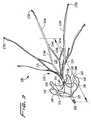
次に、先ず図1を参照して本発明のフィルタを詳細に説明する。フィルタの全体に参照番号10が付してある。フィルタは、送出するための折り畳み形状で示してある。フィルタ10は、好ましくは単一のチューブ11から形成されており、ストラット及びフィルタの部分が一体に形成されている。好ましい実施例では、フィルタチューブ11は、ニチノール、ニッケルチタニウム合金、又はエルジロイ等の形状記憶合金で形成されているが、この他のステンレス鋼等の材料を使用してもよい。フィルタ10には、好ましくはレーザーカッティング法によって複数の切欠きが形成してあるが、この他の技術を使用してもよい。例示の実施例では、六つの細長い切欠きが形成されており、これらの切欠きによって分離された実質的に均等な幅の六つのストリップ即ちストラット14を形成する。以下に詳細に説明するスペーサを形成する複数の第2切欠き34が形成されている。 Next, the filter of the present invention will be described in detail with reference to FIG.
フィルタ10の折り畳み形態は、全体プロファイルを減少し、部位への送出を容易にする。折り畳み形態でのフィルタ10の直径即ち横方向寸法は、好ましくは約2mmであり、更に好ましくは約1.7mmである。この他の寸法も考えられる。かくして、フィルタは、6フレンチの送出システム及び6フレンチのカテーテルを通して挿入するような寸法を備えている。拡張配置形態(図2参照)でのフィルタの直径即ち横方向寸法は、図1の折り畳み(送出)形態での直径即ち横方向寸法よりも大きい。 The folded configuration of the
図2は、フィルタ10の拡張配置形態を示す。フィルタ10は、全体に釣鐘形状である。フィルタ10は、末広がり領域17と、フィルタリング区分19のところの収斂領域21とを含む。末広がり(取り付け/固定)領域17でのフィルタの横方向寸法は、フィルタリング区分19のところでの横方向寸法よりも大きい。直径(即ち横方向寸法)は、好ましくは、以下に更に詳細に説明するように、血管壁の内径に応じて約18mm乃至約32mmである。この他の寸法も考えられる。細長いストラット14は、図示のように間隔が隔てられており、領域17でフィルタ10の長さ方向軸線Lから遠ざかる方向に所定の角度をなして延びている。好ましくは、この角度即ちテーパは約8°であるが、この他の寸法も考えられる。拡張させたとき、六本のストラット14は、図示のように、好ましくは、約60°の角度で間隔が隔てられる。ストラットの数をこれよりも少なくしても多くしてもよく、60°以外の角度を形成してもよい。 FIG. 2 shows an expanded arrangement of the
フィルタリング区分19は、末広がり領域17からフィルタ10の長さ方向中央軸線に向かって延びており、チューブ状部分18に収斂する。
フィルタ10のストラット14は、ストラットからほぼ垂直に延びるフック72a及び72bで終端する。これらのフックは、これらのフックが平面の外に曲げられるようにストラットを領域85のところで捩じることによって、ストラットからほぼ垂直に延びる。フック72aの第1の組は、フック72bの第2の組よりも大きい(図2A参照)。好ましくは、フック72aは、レーザーカットチューブに形成したとき、二つの隣接したストラットの横方向寸法と等しい領域を占有するように形成される。比較的小さい方のフック72bは、挿入のために折り畳み形態にある場合にフィルタの折り畳みプロファイル(横方向寸法)を最小にするため、’429出願のフィルタフックと同様に、互いに関して間隔が隔てられており且つ比較的大きいフック72aに関して軸線方向内方に間隔が隔てられている。フック72a、72bの貫入チップ76a、76bは、夫々、フィルタを、好ましくは一時的に保持し、フィルタの頭端に向かって遠位方向に(即ち血流に関して遠位側に)向けるため、組織に貫入する。The
The
フック72a、72bの各々は、好ましくは、一連の歯79a、79bと、夫々のフック72a、72bを越えて(近位側に即ち尾側に)延びる、フィルタストラット部分が血管壁を貫通しないようにするストップとして機能するヒール77a、77bとを有する。明瞭化を図るため、フックの全てに参照番号を付すことはしない。このフック形態は、2007年8月3日に出願された一般に譲渡された米国特許出願第11/888,929号に詳細に記載されている。出典を明示することにより、この出願に開示された全ての内容は本明細書の開示の一部とされる。 Each of the hooks 72a, 72b preferably extends a series of teeth 79a, 79b and a respective hook 72a, 72b (proximal or caudal) so that the filter strut portion does not penetrate the vessel wall.
六個のフィルタストラット即ちストラット部分14は、チューブ状部分18から外方に湾曲しており、チューブ状部分18から一体をなして延びており、二つの連結フィルタストラット即ちストラット部分14a、14bに分かれる。これらのストラット部分14a、14bは、互いから遠ざかる方向に(異なる方向に)角度をなして、隣接したストラット14の連結ストラット部分まで延びる。かくして、一つのストラット14の連結ストラット部分14aが、接合領域14dのところで、隣接したストラットの連結ストラット部分14bに相互連結する。これにより、閉じた幾何学的形状25を形成する。この幾何学的形状は、好ましくは、実質的に菱形である。明瞭化を図るため、同じ部分の全てに参照番号を付すことはしない。 Six filter struts or strut
例示の実施例では、好ましくは六本のストラットが設けられ、十二本の相互連結ストラットを形成するが、ストラットの数及び閉じた幾何学的形状は異なっていてもよい。全部で六本のストラット14が相互連結された状態で示してあるが、全てのストラットが相互連結されていなくてもよいと考えられる。更に、’429出願に開示されたフィルタに関して説明したように、ストラットの幅を変化させてもよい。
ストラット部分14a、14bは、接合領域14dのところで出会った後、細長い一体をなして延びる取り付けストラット部分14cに移行する。これらの取り付けストラット部分14cは、末広がりになった取り付け領域即ち固定領域17を形成する。固定領域17のストラット部分14cの長さを変化してもよく、長さの増減によりストラットの可撓性/剛性を変化する。更に、可撓性/剛性に影響を及ぼすため、ストラット部分の厚さを変化させてもよい。In the illustrated embodiment, preferably six struts are provided to form twelve interconnected struts, although the number of struts and the closed geometry may be different. Although a total of six
The
’429出願に記載された他の実施例におけるように、相互連結された、又は接合された等の用語は、説明を容易にするために使用したのであって、好ましくは、これらの部分は、好ましくは単一のチューブから形成されるため、一体であるということは理解されよう。更に、本明細書中に開示した様々な実施例を説明するために使用した取り付けストラット及びフィルタストラットは、フィルタが、例えばカッティングを施したチューブから一体成形されている場合には、同じストラットの取り付けストラット「部分」又は「区分」及びフィルタストラット「部分」又は「区分」であると考えることができる。
チューブ状部分23は、チューブ状部分18から遠位方向(血流の方向に関して)に間隔が隔てられており、フィルタ10の頭端に配置されている。チューブ状部分23は、好ましくは、’429出願の図20の実施例に関して説明されているように、回収フック92で終端する。この他の回収構造を使用してもよい。フック92を以下に簡単に説明する。As in other embodiments described in the '429 application, terms such as interconnected or joined have been used for ease of explanation, and preferably these parts are: It will be understood that they are unitary since they are preferably formed from a single tube. In addition, the mounting struts and filter struts used to illustrate the various embodiments disclosed herein may be the same strut mounting when the filter is integrally formed, for example from a cut tube. Struts “parts” or “sections” and filter struts “parts” or “sections” can be considered.
The tubular portion 23 is spaced from the tubular portion 18 in the distal direction (with respect to the direction of blood flow) and is disposed at the head end of the
製造中、好ましくはレーザーカッティングによってチューブの第3領域に複数のスロットを形成する。これにより、フィルタ用のスペーサ40を頭端部分に形成する六本のストリップを形成できる。これらのスペーサ40は、折り畳み状態では、チューブ状部分18及び23に関して実質的に整合した位置にあり、即ちこれらのチューブ状部分と実質的に面一である。チューブ状部分18、23(及び以下に説明する118、123)は、フィルタをガイドワイヤ上に通すためにガイドワイヤを通すように形態及び寸法が定められている。スペーサ40は、手術箇所への送出中、この折り畳み形態に維持される(例えば図1参照)。スペーサ40は、フィルタから半径方向に延びる図2に示す実質的にU字形状の閉鎖ループを形成する所定の形状記憶位置を有する。かくして、スペーサ40は、送出シースから露呈された後、自動的に拡張する。これは、これらのスペーサが折り畳み位置から、図2のループ状形状記憶位置まで移動するためである。フィルタの頭端が中央に置かれた状態を維持するため、及びチューブ状部分23及び回収フック92を血管壁から離しておくため、ループ40の湾曲した表面42のうちの一つ又はそれ以上が血管壁と係合できる。このように離間することにより、フックの周囲での組織の内方成長を制限し、これにより、フィルタ10を掴んで取り出すのを容易にする。 During manufacturing, a plurality of slots are formed in the third region of the tube, preferably by laser cutting. Thereby, the six strips which form the
スペーサ40のループは閉じたループ状であり、端部40aがチューブ状壁18から延びており、端部40bがチューブ状壁23から延びている。図示のように、ループ状ストラット40は、血流の方向に関し、フィルタ部分の遠位側に且つフック92の近位側に位置決めされており、内部がチューブ状部分18と一体である。図2に示す拡張形状記憶位置では、ループは、その頂点即ちループの最高高さ領域がループ40のほぼ中央にくるように延びている。かくして、これらの実質的に対称なスペーサループは、チューブ状壁23から見て、最初は半径方向外方に、及び次いで半径方向内方に延びる。ループ40を通る開口部43は、フィルタの長さ方向軸線に対して横方向である。 The loop of the
各ループ40は、好ましくは、移行部での強度を高めるため、チューブ状壁(部分)18及び23と隣接した領域に肉厚部分(図示せず)を有する。更に、これらのループは、好ましくは、幅Wがその高さよりも大きい矩形断面を備えている。約60°離間された六本のループが示してあるけれども、異なる離間距離が考えられる。更に、ループが離間機能を果たす限り、ループの数はこれよりも少数であってもよいし、多数であってもよい。
ループ状領域の横方向寸法は、取り付け(固定)領域の横方向寸法よりも小さい。換言すると、拡張形態では、ループ40の頂点から長さ方向中央軸線までの距離は、血管係合フック72a又は72bから長さ方向中央軸線までの距離よりも小さい。Each
The lateral dimension of the loop region is smaller than the lateral dimension of the attachment (fixed) region. In other words, in the expanded configuration, the distance from the apex of the
図3の変形例では、フィルタ100は、半径方向に延びるスペーサ140(対応する部分には「100番台」の参照番号が付してある)を除き、フィルタ10と同じである。スペーサ140は、閉じたループ形状をなしている。好ましくは、約60°離間された六個のループが設けられるが、これらのループは、これ以外の数及び間隔で設けられていてもよい。スペーサループ140は、血流の方向に関し、フィルタ部分119の遠位側に、及びチューブ状部分123及び回収フック192の近位側に位置決めされている。好ましくは、スペーサループ140は、フィルタと一体に形成されている。
ループ140は、遠位領域141が外方に及びフィルタの取り付け部分(即ち尾端)に向かう方向に半径方向に延びるように翼状形状をなしており、頂点領域142に達した後、領域143のところで内方に弓なりになり、領域144のところでフィルタの回収端(即ち頭端)に向かって延び、内方に弓なりになった区分を形成し、次いで領域145のところで近位方向にチューブ状部分118内に延びる。かくして、図示のように、ループ140はフィルタの回収端に向かう方向で凸状をなしている。In the modification of FIG. 3, the
The
拡張形態と折り畳み形態との間で移動できるようにするため、ここに説明した実施例のフィルタは、上述のように、好ましくは、ニチノールやニッケル−チタニウム合金等の形状記憶金属材料で形成されており、及び好ましくは、レーザーカットチューブから製造される。フィルタを送出シースの内腔を通して血管内に通すのを容易にするため、低温の塩水を、送出シース又はカテーテル内に、及び送出シース内で折り畳み状態のフィルタの周囲に注入する。この形状記憶材料は、オーステナイト状態で剛性を示し、マルテンサイト状態で可撓性を示す特徴を備えている。低温の塩水は、温度の影響を受けるフィルタを比較的柔らかな状態に維持する。これは、シース内でマルテンサイト状態にあるためである。これにより、フィルタをシースから出し易くする。これは、フィルタが剛性状態即ちオーステナイト状態に維持された場合にフィルタとシースの内面との間に生じる摩擦接触が低減されるためである。 In order to be able to move between an expanded configuration and a folded configuration, the filter of the embodiment described herein is preferably formed of a shape memory metal material such as nitinol or nickel-titanium alloy as described above. And preferably manufactured from a laser cut tube. To facilitate passing the filter through the lumen of the delivery sheath and into the blood vessel, cold saline is injected into the delivery sheath or catheter and around the filter folded within the delivery sheath. This shape memory material is characterized by exhibiting rigidity in the austenite state and flexibility in the martensite state. Cold salt water keeps the filter affected by temperature relatively soft. This is because it is in the martensite state in the sheath. This facilitates removal of the filter from the sheath. This is because the frictional contact that occurs between the filter and the inner surface of the sheath is reduced when the filter is maintained in a rigid or austenitic state.
送出シース又はカテーテルから放出されると、フィルタは、もはや低温ではなくなり、比較的高い体温に露呈され、これによりオーステナイト状態の記憶された形態に戻る。
配置(拡張)形態では、フィルタはその記憶された形態に向かって移動する。記憶された最大の形態に向かってどの程度戻るのかは、フィルタが挿入される血管の大きさで決まる(血管が大きければ大きい程、フィルタはその記憶された最大の状態に戻る)。スペーサが記憶された最大の状態まで移動する程度もまた、血管の大きさによって制限される。
フィルタは、患者の頸部の頸静脈を通して、又は患者の脚部の大腿静脈を通して、又は腕の静脈を通して挿入できる。更に、フィルタは、上大静脈に配置できる。When released from the delivery sheath or catheter, the filter is no longer cold and is exposed to a relatively high body temperature, thereby returning to the austenitic stored form.
In the deployed (expanded) configuration, the filter moves toward its stored configuration. How far back to the maximum stored form is determined by the size of the blood vessel into which the filter is inserted (the larger the blood vessel, the more the filter will return to its stored maximum state). The extent to which the spacer moves to the maximum stored state is also limited by the vessel size.
The filter can be inserted through the jugular vein in the patient's neck, through the femoral vein in the patient's leg, or through the arm vein. Furthermore, the filter can be placed in the superior vena cava.
’929出願の図13、図14、及び図15は、例えば下大静脈でのフィルタ10の送出及び配置を示す。本明細書中に開示したフィルタ10及び100は同じ方法で挿入できる。送出カテーテルを引き出すことによってフィルタ10を体温で加熱し、拡張配置形態に移行できる。本明細書中に開示した他のフィルタは、同じ方法で挿入できる。フィルタ区分19が末広がり区分17の下流に来る配向で埋め込まれるということに着目されたい。これにより、血栓又は他の粒子を、角度をなしたストラットによってフィルタ区分の中央に差し向けることができる。かくして、フィルタを送出カテーテルにどのように配置するのかは、挿入方向、例えば上流方向又は下流方向で決まる。更に、埋め込んだ状態の配向において、スペーサ40(又は140)がフィルタ区分19の下流にあるということに着目されたい。 FIGS. 13, 14, and 15 of the '929 application show delivery and placement of the
上述のフィルタは、内頸静脈又は大腿静脈を通したアクセスから取り出すことができる。フィルタの取り出しに様々な方法を使用できる。これらの方法には、一般に譲渡された、現在継続中の、2007年3月10日に出願された米国特許出願第11/801,547号に記載された方法、及び2004年7月12日に出願された米国特許出願第11/889,429号に記載された方法が含まれる。出典を明示することにより、これらの出願に開示された全ての内容は本明細書の開示の一部とされる。これらの方法は、例えば、スロットを備えたフック、グラスパー、等を含む。
好ましくは、凹所即ち切欠きがチューブ状端部分に設けられ、フック部分90(図1参照)及び190(図2参照)を形成する。最近位端に設けられた湾曲したフック92又は192が、取り出しを行うためのスネア又は他のデバイスを受け取る。これは、開示された全ての内容を本明細書の開示の一部とした米国特許出願第11/889,429号に詳細に記載されている。フック92は、図示のように、フィルタの長さ方向中央軸線から横方向にずらしてある。これにより、ガイドワイヤをフィルタに通すのが容易になる。The filter described above can be removed from access through the internal jugular vein or femoral vein. Various methods can be used to remove the filter. These methods include the commonly assigned, currently ongoing method described in US patent application Ser. No. 11 / 801,547 filed on Mar. 10, 2007, and on Jul. 12, 2004. Included are the methods described in filed US patent application Ser. No. 11 / 889,429. By specifying the source, all the contents disclosed in these applications are made part of the disclosure of this specification. These methods include, for example, a hook with a slot, a glass par, and the like.
Preferably, a recess or notch is provided in the tubular end portion to form hook portions 90 (see FIG. 1) and 190 (see FIG. 2). A
フィルタを回収デバイスで掴み、遠位方向に引っ張って血管壁と係合した状態から外すとき、スペーサが内方に撓み、回収シース又は取り出し用カテーテル内で折り畳まれる。フィルタを回収シースに引き込むとき、フィルタは、取り出しを行うために折り畳まれる。
血管からのフィルタの取り出しを容易にするため、埋め込み済のフィルタに低温の塩水を注入し、フィルタの温度を変化して比較的軟質の状態にし、回収シース内へのフィルタの回収を容易にする。即ち、低温の塩水を注入することにより、フィルタをマルテンサイト状態にし、フィルタを比較的可撓性の状態にするのである。可撓性状態であるため、折り畳みが容易になり、フィルタと回収シースの内面との間の摩擦接触を減少することによって、回収シース内へのフィルタの引き込みが容易になる。
本発明のフィルタで使用できる、フィルタカートリッジを含む送出システムは、米国特許出願第11/889,429号に記載されている。When the filter is grasped with a retrieval device and pulled distally out of engagement with the vessel wall, the spacer is deflected inward and folded within the retrieval sheath or retrieval catheter. When the filter is drawn into the collection sheath, the filter is folded for removal.
In order to facilitate removal of the filter from the blood vessel, cold saline is injected into the implanted filter, changing the temperature of the filter to a relatively soft state, facilitating the recovery of the filter into the recovery sheath. . That is, by injecting low temperature brine, the filter is in a martensite state and the filter is in a relatively flexible state. The flexible state facilitates folding and facilitates pulling of the filter into the collection sheath by reducing frictional contact between the filter and the inner surface of the collection sheath.
A delivery system including a filter cartridge that can be used with the filter of the present invention is described in US patent application Ser. No. 11 / 889,429.
以上の説明は、多くの特徴を含むけれども、これらの特徴は、本開示の範囲を限定するものと解釈されるべきではなく、その好ましい実施例の単なる例示と解釈されるべきである。例えば、上述のフィルタは、身体の他の領域に挿入できる。更に、上述のフィルタは、形状記憶材料以外の材料で形成できる。本明細書に添付した特許請求の範囲によって定義された本開示の範囲及び精神内でこの他の多くの変更を行うことができるということは当業者には理解されよう。 Although the foregoing description includes many features, these features should not be construed as limiting the scope of the present disclosure, but merely as exemplifications of preferred embodiments thereof. For example, the filter described above can be inserted into other areas of the body. Furthermore, the above-described filter can be formed of a material other than the shape memory material. Those skilled in the art will recognize that many other changes can be made within the scope and spirit of the present disclosure as defined by the claims appended hereto.
10 フィルタ
11 チューブ
14 ストラット
17 末広がり領域
18 チューブ状部分
19 フィルタリング区分
21 収斂領域
72a、72b フック
76a、76b 貫入チップ
79a、79b 歯
77a、77b ヒールDESCRIPTION OF
Claims (15)
Translated fromJapanese前記第1領域は、粒子を前記フィルタの中央に向かって差し向けるための先細領域を持つフィルタ部分を有し、前記第1領域は、間隔が隔てられた複数の細長いストラットと、これらの細長いストラットから所定角度をなして延び、閉じた幾何学的形状を形成する複数の連結ストラットとを含み、
前記第2領域は、前記拡張位置において末広がりになっており、横方向寸法が前記フィルタ部分とは反対側の第2端部分に向かって増大し、前記第2端部分は、前記フィルタの近位領域にあり、前記第2領域は前記第2端部分に血管係合フックを有し、
前記第3領域は、前記拡張位置において前記フィルタの長さ方向軸線に関して半径方向に延びる複数の閉じたループ状のスペーサストラットを有し、
複数の一体の閉じた翼状形状をなしたループ状ストラットが前記フィルタ部分の遠位側に位置決めされており、
各ループは、前記フィルタの長さ方向中央軸線から、長さ方向中央軸線からの前記血管係合フックの距離よりも小さい所定距離だけ延びている、血管フィルタ。In a vascular filter that includes a first region, a second region, and a third region and is movable between a folded position for delivery to a blood vessel and an expanded position for placement within the blood vessel,
The first region has a filter portion having a tapered region for directing particles toward the center of the filter, the first region comprising a plurality of spaced apart struts and the elongated struts. A plurality of connecting struts extending at an angle from and forming a closed geometric shape,
The second region is divergent in the expanded position, with a lateral dimension increasing toward a second end portion opposite the filter portion, the second end portion being proximal to the filter. The second region has a vascular engagement hook at the second end portion;
The third region has a plurality of closed loop spacer struts extending radially with respect to a longitudinal axis of the filter in the extended position;
A plurality of integral closed wing-shaped looped struts are positioned distal to the filter portion;
Each loop extends from the longitudinal central axis of the filter by a predetermined distance that is less than the distance of the vascular engagement hook from the longitudinal central axis.
前記ループ状スペーサストラットの領域での前記フィルタの横方向寸法は、血管係合部分の領域での前記フィルタの横方向寸法よりも小さい、血管フィルタ。The vascular filter according to claim 1, wherein
The vascular filter, wherein a lateral dimension of the filter in the region of the loop spacer strut is smaller than a lateral dimension of the filter in the region of the blood vessel engaging portion.
前記スペーサストラットは、これらのストラットが折り畳み位置にあるとき、前記フィルタの長さ方向軸線に関して実質的に整合している、血管フィルタ。The vascular filter according to claim 1 or 2,
The vascular filter, wherein the spacer struts are substantially aligned with respect to the longitudinal axis of the filter when the struts are in a folded position.
前記拡張形態では、前記ループの開口部は、前記フィルタの長さ方向軸線に対して横方向である、血管フィルタ。The vascular filter according to claim 3,
In the expanded configuration, the vascular filter, wherein the opening of the loop is transverse to the longitudinal axis of the filter.
前記フィルタはレーザーカットチューブから形成されており、形状記憶材料で形成されており、前記スペーサストラットは、前記フィルタと一体成形されており、形状記憶材料で形成されている、血管フィルタ。In the vascular filter of any one of Claims 1-4,
The blood vessel filter, wherein the filter is formed of a laser cut tube, is formed of a shape memory material, and the spacer strut is integrally formed with the filter and is formed of a shape memory material.
前記先細領域はチューブ状部分で終端し、前記細長いストラットの各々は、前記第1領域において、前記チューブ状部分から外方に延びており、前記スペーサストラットは前記チューブ状部分から半径方向に延びており、前記細長いストラットの遠位側に位置決めされている、血管フィルタ。The vascular filter according to any one of claims 1 to 5,
The tapered region terminates in a tubular portion, each of the elongated struts extends outward from the tubular portion in the first region, and the spacer struts extend radially from the tubular portion. A vascular filter positioned on a distal side of the elongated strut.
前記スペーサストラットはループ状記憶位置を有し、送出中、前記チューブ部分と実質的に面一の折り畳み位置をとる、血管フィルタ。The vascular filter according to claim 6, wherein
The vascular filter, wherein the spacer strut has a looped memory position and assumes a folded position substantially flush with the tube portion during delivery.
前記スペーサストラットは、前記フィルタの第1端から半径方向に、前記フィルタの前記近位領域に向かう第1方向に端部領域まで延びた後、逆の第2方向に前記フィルタの前記遠位端に向かって内方に湾曲している、血管フィルタ。The vascular filter according to any one of claims 1 to 7,
The spacer struts extend radially from the first end of the filter to an end region in a first direction toward the proximal region of the filter and then in the opposite second direction the distal end of the filter A vascular filter that curves inwardly toward.
前記フィルタは、前記スペーサストラットの近位側のチューブ状第1部分及び前記スペーサストラットの遠位側のチューブ状第2部分含み、これらの第1及び第2のチューブ状部分は、ガイドワイヤを受け取って通すような寸法を備えている、血管フィルタ。The vascular filter according to any one of claims 1 to 8,
The filter includes a tubular first portion proximal to the spacer strut and a tubular second portion distal to the spacer strut, the first and second tubular portions receiving a guide wire. A blood vessel filter with dimensions that allow it to pass through.
前記スペーサストラットは、送出シースから露呈されたときに自動的に拡張する、血管フィルタ。The vascular filter according to any one of claims 1 to 9,
The vascular filter, wherein the spacer struts automatically expand when exposed from the delivery sheath.
前記フィルタの遠位端に設けられた回収フックを含み、このフックは、ガイドワイヤの通過を容易にするため、前記フィルタの長さ方向中央軸線から横方向にずらしてある、血管フィルタ。The vascular filter according to any one of claims 1 to 10, further comprising:
A vascular filter comprising a retrieval hook provided at a distal end of the filter, the hook being laterally offset from a central longitudinal axis of the filter to facilitate passage of a guide wire.
前記フィルタは、前記本体の前記フィルタ領域に相互連結ストラットを含み、閉じた幾何学的形状を形成する、血管フィルタ。The vascular filter according to any one of claims 1 to 12,
The vascular filter, wherein the filter includes interconnected struts in the filter region of the body to form a closed geometry.
前記フィルタの壁は、前記ループ状ストラットを前記フィルタ部分から離間する、血管フィルタ。The vascular filter according to any one of claims 1 to 13,
The vascular filter, wherein the filter wall separates the loop strut from the filter portion.
チューブ状部分と、
前記チューブ状部分から一体をなして延び、前記チューブ状部分から外方に湾曲した複数の細長いストラットとを含み、これらのストラットの各々は、近位端部分に一体成形された血管係合フックで終端し、前記チューブの中間部分がフィルタを形成し、更に、
前記フィルタ部分の遠位側に位置決めされた、前記細長いストラットと一体成形された複数の閉じた翼状形状をなしたループ状のストラットを含み、前記ループの各々は、前記フィルタの長さ方向中央軸線から、前記長さ方向中央軸線から前記血管係合フックまでの距離よりも小さい所定距離延びている、血管フィルタ。In the vascular filter,
A tubular part;
A plurality of elongated struts extending integrally from the tubular portion and curved outwardly from the tubular portion, each of these struts being a vascular engagement hook integrally formed on the proximal end portion. Terminating, the middle part of the tube forms a filter,
A plurality of closed wing-shaped looped struts integrally formed with the elongated struts positioned distally of the filter portion, each of the loops having a longitudinal central axis of the filter; A vascular filter extending a predetermined distance less than a distance from the longitudinal central axis to the vascular engagement hook.
Applications Claiming Priority (3)
| Application Number | Priority Date | Filing Date | Title |
|---|---|---|---|
| US1083708P | 2008-01-11 | 2008-01-11 | |
| US61/010,837 | 2008-01-11 | ||
| PCT/US2009/000019WO2009088970A1 (en) | 2008-01-11 | 2009-01-05 | Vein filter |
Publications (2)
| Publication Number | Publication Date |
|---|---|
| JP2011509149A JP2011509149A (en) | 2011-03-24 |
| JP5616795B2true JP5616795B2 (en) | 2014-10-29 |
Family
ID=40451337
Family Applications (1)
| Application Number | Title | Priority Date | Filing Date |
|---|---|---|---|
| JP2010542254AExpired - Fee RelatedJP5616795B2 (en) | 2008-01-11 | 2009-01-05 | Venous filter |
Country Status (7)
| Country | Link |
|---|---|
| US (1) | US20090198270A1 (en) |
| EP (1) | EP2252236B1 (en) |
| JP (1) | JP5616795B2 (en) |
| AU (1) | AU2009204529B2 (en) |
| CA (1) | CA2711813A1 (en) |
| ES (1) | ES2449596T3 (en) |
| WO (1) | WO2009088970A1 (en) |
Families Citing this family (36)
| Publication number | Priority date | Publication date | Assignee | Title |
|---|---|---|---|---|
| US7314477B1 (en) | 1998-09-25 | 2008-01-01 | C.R. Bard Inc. | Removable embolus blood clot filter and filter delivery unit |
| US9204956B2 (en) | 2002-02-20 | 2015-12-08 | C. R. Bard, Inc. | IVC filter with translating hooks |
| US7704266B2 (en) | 2004-01-22 | 2010-04-27 | Rex Medical, L.P. | Vein filter |
| US7976562B2 (en) | 2004-01-22 | 2011-07-12 | Rex Medical, L.P. | Method of removing a vein filter |
| US8500774B2 (en) | 2004-01-22 | 2013-08-06 | Rex Medical, L.P. | Vein filter |
| US8062326B2 (en) | 2004-01-22 | 2011-11-22 | Rex Medical, L.P. | Vein filter |
| US8162972B2 (en)* | 2004-01-22 | 2012-04-24 | Rex Medical, Lp | Vein filter |
| US7704267B2 (en) | 2004-08-04 | 2010-04-27 | C. R. Bard, Inc. | Non-entangling vena cava filter |
| US8613754B2 (en) | 2005-05-12 | 2013-12-24 | C. R. Bard, Inc. | Tubular filter |
| US12115057B2 (en) | 2005-05-12 | 2024-10-15 | C.R. Bard, Inc. | Tubular filter |
| CA2607580C (en) | 2005-05-12 | 2016-12-20 | C.R. Bard Inc. | Removable embolus blood clot filter |
| WO2007021340A1 (en) | 2005-08-09 | 2007-02-22 | C.R. Bard Inc | Embolus blood clot filter and delivery system |
| US9131999B2 (en) | 2005-11-18 | 2015-09-15 | C.R. Bard Inc. | Vena cava filter with filament |
| WO2007133366A2 (en) | 2006-05-02 | 2007-11-22 | C. R. Bard, Inc. | Vena cava filter formed from a sheet |
| US9326842B2 (en) | 2006-06-05 | 2016-05-03 | C. R . Bard, Inc. | Embolus blood clot filter utilizable with a single delivery system or a single retrieval system in one of a femoral or jugular access |
| US10076401B2 (en)* | 2006-08-29 | 2018-09-18 | Argon Medical Devices, Inc. | Vein filter |
| WO2009032834A1 (en) | 2007-09-07 | 2009-03-12 | Crusader Medical Llc | Percutaneous permanent retrievable vascular filter |
| US8795318B2 (en) | 2007-09-07 | 2014-08-05 | Merit Medical Systems, Inc. | Percutaneous retrievable vascular filter |
| EP2211765B1 (en) | 2007-11-02 | 2024-04-17 | Argon Medical Devices, Inc. | Vein filter |
| US20120035647A1 (en)* | 2008-12-17 | 2012-02-09 | Rainer Bregulla | Body lumen filters with large surface area anchors |
| US8057507B2 (en) | 2009-01-16 | 2011-11-15 | Novate Medical Limited | Vascular filter |
| US20110152918A1 (en)* | 2009-12-23 | 2011-06-23 | Pavilion Medical Innovations | Reversible Vascular Filter Devices and Methods for Using Same |
| US8740931B2 (en) | 2011-08-05 | 2014-06-03 | Merit Medical Systems, Inc. | Vascular filter |
| US8734480B2 (en) | 2011-08-05 | 2014-05-27 | Merit Medical Systems, Inc. | Vascular filter |
| CN104023656B (en)* | 2011-12-05 | 2017-02-15 | Pi-R-方形有限公司 | Calcium deposits in broken heart valves |
| EP2816969B1 (en) | 2012-02-23 | 2018-06-13 | Merit Medical Systems, Inc. | Vascular filter |
| US20140046347A1 (en)* | 2012-08-10 | 2014-02-13 | W. L. Gore & Associates, Inc. | Devices, systems and methods for engaging tissue |
| FR2998164B1 (en)* | 2012-11-20 | 2016-05-27 | Braun B Med Sas | VEIN FILTER |
| US9345564B2 (en)* | 2013-03-15 | 2016-05-24 | Cook Medical Technologies Llc | Removable vena cava filter having primary and secondary struts |
| EP3030194B1 (en) | 2013-08-09 | 2019-03-13 | Merit Medical Systems, Inc. | Vascular filter delivery systems |
| ES2614488T3 (en)* | 2014-03-15 | 2017-05-31 | Argon Medical Devices, Inc. | Vein filter |
| GB2531019A (en) | 2014-10-07 | 2016-04-13 | Cook Medical Technologies Llc | Implantable medical device with improved orientation |
| CN104970900B (en)* | 2015-06-26 | 2017-10-17 | 深圳市科奕顿生物医疗科技有限公司 | Recyclable thrombus filter |
| US10856963B2 (en)* | 2017-04-11 | 2020-12-08 | Hangzhou Wei Qiang Medical Technology Co., Ltd. | Inferior vena cava filter of bidirectional controlled placement |
| CN110507447A (en)* | 2019-09-24 | 2019-11-29 | 浙江归创医疗器械有限公司 | Vena cava filter and its recyclable device |
| KR20210049550A (en)* | 2019-10-25 | 2021-05-06 | 경북대학교 산학협력단 | Blood filter and device for removing thrombus |
Family Cites Families (54)
| Publication number | Priority date | Publication date | Assignee | Title |
|---|---|---|---|---|
| US186556A (en)* | 1877-01-23 | Improvement in reversible knob-latches | ||
| US3744492A (en)* | 1971-04-07 | 1973-07-10 | S Leibinsohn | Drip chamber |
| US3952747A (en)* | 1974-03-28 | 1976-04-27 | Kimmell Jr Garman O | Filter and filter insertion instrument |
| NL185061C (en)* | 1978-07-03 | 1990-01-16 | Smiths Industries Plc | CONNECTING DEVICE. |
| US4425908A (en) | 1981-10-22 | 1984-01-17 | Beth Israel Hospital | Blood clot filter |
| US4643184A (en)* | 1982-09-29 | 1987-02-17 | Mobin Uddin Kazi | Embolus trap |
| US4494531A (en)* | 1982-12-06 | 1985-01-22 | Cook, Incorporated | Expandable blood clot filter |
| US4512338A (en)* | 1983-01-25 | 1985-04-23 | Balko Alexander B | Process for restoring patency to body vessels |
| US4727873A (en)* | 1984-04-17 | 1988-03-01 | Mobin Uddin Kazi | Embolus trap |
| DK151404C (en)* | 1984-05-23 | 1988-07-18 | Cook Europ Aps William | FULLY FILTER FOR IMPLANTATION IN A PATIENT'S BLOOD |
| FR2573646B1 (en)* | 1984-11-29 | 1988-11-25 | Celsa Composants Electr Sa | PERFECTED FILTER, PARTICULARLY FOR THE RETENTION OF BLOOD CLOTS |
| US4781173A (en) | 1985-06-28 | 1988-11-01 | Juha Ven | Evaporating device and electric supply station provided with such an evaporating device |
| US4793348A (en)* | 1986-11-15 | 1988-12-27 | Palmaz Julio C | Balloon expandable vena cava filter to prevent migration of lower extremity venous clots into the pulmonary circulation |
| FR2606641B1 (en)* | 1986-11-17 | 1991-07-12 | Promed | FILTERING DEVICE FOR BLOOD CLOTS |
| US4817600A (en)* | 1987-05-22 | 1989-04-04 | Medi-Tech, Inc. | Implantable filter |
| US4832055A (en)* | 1988-07-08 | 1989-05-23 | Palestrant Aubrey M | Mechanically locking blood clot filter |
| US5059205A (en) | 1989-09-07 | 1991-10-22 | Boston Scientific Corporation | Percutaneous anti-migration vena cava filter |
| US6059825A (en) | 1992-03-05 | 2000-05-09 | Angiodynamics, Inc. | Clot filter |
| US6214025B1 (en) | 1994-11-30 | 2001-04-10 | Boston Scientific Corporation | Self-centering, self-expanding and retrievable vena cava filter |
| US5893869A (en) | 1997-02-19 | 1999-04-13 | University Of Iowa Research Foundation | Retrievable inferior vena cava filter system and method for use thereof |
| US5800457A (en)* | 1997-03-05 | 1998-09-01 | Gelbfish; Gary A. | Intravascular filter and associated methodology |
| US5984947A (en) | 1998-05-04 | 1999-11-16 | Scimed Life Systems, Inc. | Removable thrombus filter |
| US6331183B1 (en)* | 1998-09-24 | 2001-12-18 | Scimed Life Systems, Inc. | Basket filter |
| US6007558A (en) | 1998-09-25 | 1999-12-28 | Nitinol Medical Technologies, Inc. | Removable embolus blood clot filter |
| US6368338B1 (en)* | 1999-03-05 | 2002-04-09 | Board Of Regents, The University Of Texas | Occlusion method and apparatus |
| US6589265B1 (en)* | 2000-10-31 | 2003-07-08 | Endovascular Technologies, Inc. | Intrasaccular embolic device |
| US7011094B2 (en)* | 2001-03-02 | 2006-03-14 | Emphasys Medical, Inc. | Bronchial flow control devices and methods of use |
| US7674245B2 (en)* | 2001-06-07 | 2010-03-09 | Cardiac Pacemakers, Inc. | Method and apparatus for an adjustable shape guide catheter |
| JP4294470B2 (en)* | 2001-06-14 | 2009-07-15 | クック インコーポレイテッド | Intravascular filter |
| WO2004049973A1 (en)* | 2002-11-29 | 2004-06-17 | Vascular Interventional Technologies Inc. | Embolus blood clot filter |
| US20050165469A1 (en)* | 2002-12-24 | 2005-07-28 | Michael Hogendijk | Vascular prosthesis including torsional stabilizer and methods of use |
| WO2004069290A2 (en)* | 2003-01-31 | 2004-08-19 | Cordis Corporation | Filter retrieval catheter system, and methods |
| US8361103B2 (en)* | 2003-02-07 | 2013-01-29 | Karla Weaver | Low profile IVC filter |
| US7534251B2 (en)* | 2003-02-11 | 2009-05-19 | Boston Scientific Scimed, Inc. | Retrievable IVC filter |
| US7896898B2 (en)* | 2003-07-30 | 2011-03-01 | Boston Scientific Scimed, Inc. | Self-centering blood clot filter |
| US7338512B2 (en)* | 2004-01-22 | 2008-03-04 | Rex Medical, L.P. | Vein filter |
| US7976562B2 (en) | 2004-01-22 | 2011-07-12 | Rex Medical, L.P. | Method of removing a vein filter |
| US8062326B2 (en) | 2004-01-22 | 2011-11-22 | Rex Medical, L.P. | Vein filter |
| US8500774B2 (en)* | 2004-01-22 | 2013-08-06 | Rex Medical, L.P. | Vein filter |
| US7704266B2 (en) | 2004-01-22 | 2010-04-27 | Rex Medical, L.P. | Vein filter |
| DE602005019029D1 (en)* | 2004-01-27 | 2010-03-11 | Med Inst Inc | RESISTANCE TO FIXING TO A MEDICAL PROSTHESIS |
| WO2005077303A2 (en)* | 2004-02-09 | 2005-08-25 | The Government Of The United States Of America As Represented By The Secretary, Department Of Health And Human Services | Venous filter with detachable fixation members and a venous filter with adjustable biodegradability |
| US8998944B2 (en)* | 2004-06-10 | 2015-04-07 | Lifescreen Sciences Llc | Invertible intravascular filter |
| ES2444590T3 (en)* | 2004-09-27 | 2014-02-25 | Rex Medical, L.P. | Venous filter |
| US7279000B2 (en)* | 2004-09-29 | 2007-10-09 | Angiodynamics Inc | Permanent blood clot filter with capability of being retrieved |
| US7959645B2 (en)* | 2004-11-03 | 2011-06-14 | Boston Scientific Scimed, Inc. | Retrievable vena cava filter |
| US8029529B1 (en)* | 2005-01-19 | 2011-10-04 | C. R. Bard, Inc. | Retrievable filter |
| US7998164B2 (en)* | 2005-03-11 | 2011-08-16 | Boston Scientific Scimed, Inc. | Intravascular filter with centering member |
| CA2631295A1 (en)* | 2006-01-20 | 2007-07-26 | Angiodynamics, Inc. | Retrievable blood clot filter |
| EP1894543B1 (en)* | 2006-08-29 | 2012-03-21 | Rex Medical, L.P. | Vein filter |
| WO2008077067A2 (en)* | 2006-12-19 | 2008-06-26 | C.R. Bard Inc. | Inferior vena cava filter with stability features |
| US20080188887A1 (en)* | 2007-02-07 | 2008-08-07 | Stanley Batiste | Removable vascular filter and method of filter placement |
| US20080275486A1 (en)* | 2007-05-01 | 2008-11-06 | Clifford Dwyer | Extended duration medical filter |
| US8986338B2 (en)* | 2008-10-29 | 2015-03-24 | Cook Biotech Incorporated | Vascular plugs |
- 2009
- 2009-01-05CACA2711813Apatent/CA2711813A1/ennot_activeAbandoned
- 2009-01-05JPJP2010542254Apatent/JP5616795B2/ennot_activeExpired - Fee Related
- 2009-01-05WOPCT/US2009/000019patent/WO2009088970A1/enactiveApplication Filing
- 2009-01-05AUAU2009204529Apatent/AU2009204529B2/ennot_activeCeased
- 2009-01-05EPEP09701339.5Apatent/EP2252236B1/ennot_activeNot-in-force
- 2009-01-05ESES09701339.5Tpatent/ES2449596T3/enactiveActive
- 2009-01-05USUS12/319,277patent/US20090198270A1/ennot_activeAbandoned
Also Published As
| Publication number | Publication date |
|---|---|
| AU2009204529B2 (en) | 2013-10-17 |
| AU2009204529A1 (en) | 2009-07-16 |
| JP2011509149A (en) | 2011-03-24 |
| US20090198270A1 (en) | 2009-08-06 |
| CA2711813A1 (en) | 2009-07-16 |
| EP2252236A1 (en) | 2010-11-24 |
| EP2252236B1 (en) | 2013-12-04 |
| WO2009088970A1 (en) | 2009-07-16 |
| ES2449596T3 (en) | 2014-03-20 |
Similar Documents
| Publication | Publication Date | Title |
|---|---|---|
| JP5616795B2 (en) | Venous filter | |
| US8062326B2 (en) | Vein filter | |
| US7909847B2 (en) | Vein filter | |
| US8864793B2 (en) | Vein filter | |
| US9763766B2 (en) | Vein filter | |
| US7179275B2 (en) | Vein filter | |
| US7338512B2 (en) | Vein filter | |
| US8211140B2 (en) | Vein filter | |
| US8162972B2 (en) | Vein filter | |
| US20050015111A1 (en) | Vein filter | |
| EP2258310B1 (en) | Vein filter | |
| WO2004098460A1 (en) | Vein filter | |
| US9510929B2 (en) | Vein filter | |
| US10076401B2 (en) | Vein filter |
Legal Events
| Date | Code | Title | Description |
|---|---|---|---|
| A621 | Written request for application examination | Free format text:JAPANESE INTERMEDIATE CODE: A621 Effective date:20111128 | |
| A131 | Notification of reasons for refusal | Free format text:JAPANESE INTERMEDIATE CODE: A131 Effective date:20130522 | |
| A521 | Request for written amendment filed | Free format text:JAPANESE INTERMEDIATE CODE: A523 Effective date:20130822 | |
| A131 | Notification of reasons for refusal | Free format text:JAPANESE INTERMEDIATE CODE: A131 Effective date:20140127 | |
| A521 | Request for written amendment filed | Free format text:JAPANESE INTERMEDIATE CODE: A523 Effective date:20140325 | |
| TRDD | Decision of grant or rejection written | ||
| A01 | Written decision to grant a patent or to grant a registration (utility model) | Free format text:JAPANESE INTERMEDIATE CODE: A01 Effective date:20140813 | |
| A61 | First payment of annual fees (during grant procedure) | Free format text:JAPANESE INTERMEDIATE CODE: A61 Effective date:20140912 | |
| R150 | Certificate of patent or registration of utility model | Ref document number:5616795 Country of ref document:JP Free format text:JAPANESE INTERMEDIATE CODE: R150 | |
| LAPS | Cancellation because of no payment of annual fees |