JP5616591B2 - Semiconductor device manufacturing method and substrate processing apparatus - Google Patents
Semiconductor device manufacturing method and substrate processing apparatusDownload PDFInfo
- Publication number
- JP5616591B2 JP5616591B2JP2009114862AJP2009114862AJP5616591B2JP 5616591 B2JP5616591 B2JP 5616591B2JP 2009114862 AJP2009114862 AJP 2009114862AJP 2009114862 AJP2009114862 AJP 2009114862AJP 5616591 B2JP5616591 B2JP 5616591B2
- Authority
- JP
- Japan
- Prior art keywords
- ozone
- processing chamber
- gas
- valve
- substrate
- Prior art date
- Legal status (The legal status is an assumption and is not a legal conclusion. Google has not performed a legal analysis and makes no representation as to the accuracy of the status listed.)
- Active
Links
Images


Classifications
- H—ELECTRICITY
- H01—ELECTRIC ELEMENTS
- H01L—SEMICONDUCTOR DEVICES NOT COVERED BY CLASS H10
- H01L21/00—Processes or apparatus adapted for the manufacture or treatment of semiconductor or solid state devices or of parts thereof
- H01L21/02—Manufacture or treatment of semiconductor devices or of parts thereof
- H01L21/02104—Forming layers
- H01L21/02107—Forming insulating materials on a substrate
- H01L21/02225—Forming insulating materials on a substrate characterised by the process for the formation of the insulating layer
- H01L21/0226—Forming insulating materials on a substrate characterised by the process for the formation of the insulating layer formation by a deposition process
- H01L21/02263—Forming insulating materials on a substrate characterised by the process for the formation of the insulating layer formation by a deposition process deposition from the gas or vapour phase
- H01L21/02271—Forming insulating materials on a substrate characterised by the process for the formation of the insulating layer formation by a deposition process deposition from the gas or vapour phase deposition by decomposition or reaction of gaseous or vapour phase compounds, i.e. chemical vapour deposition
- H01L21/0228—Forming insulating materials on a substrate characterised by the process for the formation of the insulating layer formation by a deposition process deposition from the gas or vapour phase deposition by decomposition or reaction of gaseous or vapour phase compounds, i.e. chemical vapour deposition deposition by cyclic CVD, e.g. ALD, ALE, pulsed CVD
- C—CHEMISTRY; METALLURGY
- C23—COATING METALLIC MATERIAL; COATING MATERIAL WITH METALLIC MATERIAL; CHEMICAL SURFACE TREATMENT; DIFFUSION TREATMENT OF METALLIC MATERIAL; COATING BY VACUUM EVAPORATION, BY SPUTTERING, BY ION IMPLANTATION OR BY CHEMICAL VAPOUR DEPOSITION, IN GENERAL; INHIBITING CORROSION OF METALLIC MATERIAL OR INCRUSTATION IN GENERAL
- C23C—COATING METALLIC MATERIAL; COATING MATERIAL WITH METALLIC MATERIAL; SURFACE TREATMENT OF METALLIC MATERIAL BY DIFFUSION INTO THE SURFACE, BY CHEMICAL CONVERSION OR SUBSTITUTION; COATING BY VACUUM EVAPORATION, BY SPUTTERING, BY ION IMPLANTATION OR BY CHEMICAL VAPOUR DEPOSITION, IN GENERAL
- C23C16/00—Chemical coating by decomposition of gaseous compounds, without leaving reaction products of surface material in the coating, i.e. chemical vapour deposition [CVD] processes
- C23C16/22—Chemical coating by decomposition of gaseous compounds, without leaving reaction products of surface material in the coating, i.e. chemical vapour deposition [CVD] processes characterised by the deposition of inorganic material, other than metallic material
- C23C16/30—Deposition of compounds, mixtures or solid solutions, e.g. borides, carbides, nitrides
- C23C16/40—Oxides
- C23C16/405—Oxides of refractory metals or yttrium
- C—CHEMISTRY; METALLURGY
- C23—COATING METALLIC MATERIAL; COATING MATERIAL WITH METALLIC MATERIAL; CHEMICAL SURFACE TREATMENT; DIFFUSION TREATMENT OF METALLIC MATERIAL; COATING BY VACUUM EVAPORATION, BY SPUTTERING, BY ION IMPLANTATION OR BY CHEMICAL VAPOUR DEPOSITION, IN GENERAL; INHIBITING CORROSION OF METALLIC MATERIAL OR INCRUSTATION IN GENERAL
- C23C—COATING METALLIC MATERIAL; COATING MATERIAL WITH METALLIC MATERIAL; SURFACE TREATMENT OF METALLIC MATERIAL BY DIFFUSION INTO THE SURFACE, BY CHEMICAL CONVERSION OR SUBSTITUTION; COATING BY VACUUM EVAPORATION, BY SPUTTERING, BY ION IMPLANTATION OR BY CHEMICAL VAPOUR DEPOSITION, IN GENERAL
- C23C16/00—Chemical coating by decomposition of gaseous compounds, without leaving reaction products of surface material in the coating, i.e. chemical vapour deposition [CVD] processes
- C23C16/44—Chemical coating by decomposition of gaseous compounds, without leaving reaction products of surface material in the coating, i.e. chemical vapour deposition [CVD] processes characterised by the method of coating
- C23C16/4412—Details relating to the exhausts, e.g. pumps, filters, scrubbers, particle traps
- C—CHEMISTRY; METALLURGY
- C23—COATING METALLIC MATERIAL; COATING MATERIAL WITH METALLIC MATERIAL; CHEMICAL SURFACE TREATMENT; DIFFUSION TREATMENT OF METALLIC MATERIAL; COATING BY VACUUM EVAPORATION, BY SPUTTERING, BY ION IMPLANTATION OR BY CHEMICAL VAPOUR DEPOSITION, IN GENERAL; INHIBITING CORROSION OF METALLIC MATERIAL OR INCRUSTATION IN GENERAL
- C23C—COATING METALLIC MATERIAL; COATING MATERIAL WITH METALLIC MATERIAL; SURFACE TREATMENT OF METALLIC MATERIAL BY DIFFUSION INTO THE SURFACE, BY CHEMICAL CONVERSION OR SUBSTITUTION; COATING BY VACUUM EVAPORATION, BY SPUTTERING, BY ION IMPLANTATION OR BY CHEMICAL VAPOUR DEPOSITION, IN GENERAL
- C23C16/00—Chemical coating by decomposition of gaseous compounds, without leaving reaction products of surface material in the coating, i.e. chemical vapour deposition [CVD] processes
- C23C16/44—Chemical coating by decomposition of gaseous compounds, without leaving reaction products of surface material in the coating, i.e. chemical vapour deposition [CVD] processes characterised by the method of coating
- C23C16/455—Chemical coating by decomposition of gaseous compounds, without leaving reaction products of surface material in the coating, i.e. chemical vapour deposition [CVD] processes characterised by the method of coating characterised by the method used for introducing gases into reaction chamber or for modifying gas flows in reaction chamber
- C23C16/45523—Pulsed gas flow or change of composition over time
- C23C16/45525—Atomic layer deposition [ALD]
- C23C16/45527—Atomic layer deposition [ALD] characterized by the ALD cycle, e.g. different flows or temperatures during half-reactions, unusual pulsing sequence, use of precursor mixtures or auxiliary reactants or activations
- C—CHEMISTRY; METALLURGY
- C23—COATING METALLIC MATERIAL; COATING MATERIAL WITH METALLIC MATERIAL; CHEMICAL SURFACE TREATMENT; DIFFUSION TREATMENT OF METALLIC MATERIAL; COATING BY VACUUM EVAPORATION, BY SPUTTERING, BY ION IMPLANTATION OR BY CHEMICAL VAPOUR DEPOSITION, IN GENERAL; INHIBITING CORROSION OF METALLIC MATERIAL OR INCRUSTATION IN GENERAL
- C23C—COATING METALLIC MATERIAL; COATING MATERIAL WITH METALLIC MATERIAL; SURFACE TREATMENT OF METALLIC MATERIAL BY DIFFUSION INTO THE SURFACE, BY CHEMICAL CONVERSION OR SUBSTITUTION; COATING BY VACUUM EVAPORATION, BY SPUTTERING, BY ION IMPLANTATION OR BY CHEMICAL VAPOUR DEPOSITION, IN GENERAL
- C23C16/00—Chemical coating by decomposition of gaseous compounds, without leaving reaction products of surface material in the coating, i.e. chemical vapour deposition [CVD] processes
- C23C16/44—Chemical coating by decomposition of gaseous compounds, without leaving reaction products of surface material in the coating, i.e. chemical vapour deposition [CVD] processes characterised by the method of coating
- C23C16/455—Chemical coating by decomposition of gaseous compounds, without leaving reaction products of surface material in the coating, i.e. chemical vapour deposition [CVD] processes characterised by the method of coating characterised by the method used for introducing gases into reaction chamber or for modifying gas flows in reaction chamber
- C23C16/45557—Pulsed pressure or control pressure
- H—ELECTRICITY
- H01—ELECTRIC ELEMENTS
- H01L—SEMICONDUCTOR DEVICES NOT COVERED BY CLASS H10
- H01L21/00—Processes or apparatus adapted for the manufacture or treatment of semiconductor or solid state devices or of parts thereof
- H01L21/02—Manufacture or treatment of semiconductor devices or of parts thereof
- H01L21/02104—Forming layers
- H01L21/02107—Forming insulating materials on a substrate
- H01L21/02109—Forming insulating materials on a substrate characterised by the type of layer, e.g. type of material, porous/non-porous, pre-cursors, mixtures or laminates
- H01L21/02112—Forming insulating materials on a substrate characterised by the type of layer, e.g. type of material, porous/non-porous, pre-cursors, mixtures or laminates characterised by the material of the layer
- H—ELECTRICITY
- H01—ELECTRIC ELEMENTS
- H01L—SEMICONDUCTOR DEVICES NOT COVERED BY CLASS H10
- H01L21/00—Processes or apparatus adapted for the manufacture or treatment of semiconductor or solid state devices or of parts thereof
- H01L21/02—Manufacture or treatment of semiconductor devices or of parts thereof
- H01L21/02104—Forming layers
- H01L21/02107—Forming insulating materials on a substrate
- H01L21/02109—Forming insulating materials on a substrate characterised by the type of layer, e.g. type of material, porous/non-porous, pre-cursors, mixtures or laminates
- H01L21/02205—Forming insulating materials on a substrate characterised by the type of layer, e.g. type of material, porous/non-porous, pre-cursors, mixtures or laminates the layer being characterised by the precursor material for deposition
Landscapes
- Chemical & Material Sciences (AREA)
- Engineering & Computer Science (AREA)
- Chemical Kinetics & Catalysis (AREA)
- General Chemical & Material Sciences (AREA)
- Materials Engineering (AREA)
- Mechanical Engineering (AREA)
- Metallurgy (AREA)
- Organic Chemistry (AREA)
- Physics & Mathematics (AREA)
- Condensed Matter Physics & Semiconductors (AREA)
- General Physics & Mathematics (AREA)
- Manufacturing & Machinery (AREA)
- Computer Hardware Design (AREA)
- Microelectronics & Electronic Packaging (AREA)
- Power Engineering (AREA)
- Inorganic Chemistry (AREA)
- Chemical Vapour Deposition (AREA)
- Formation Of Insulating Films (AREA)
Description
Translated fromJapanese本発明は、基板処理方法及び基板処理装置に関するものである。 The present invention relates to a substrate processing method and a substrate processing apparatus.
IC等の半導体装置の製造工程の一工程として、ALD(Atomic Layer Deposition)法やCVD(Chemical Vapor Deposition)法を用いた基板処理工程が行われている。基板処理工程を実施する基板処理装置として、縦型の基板処理装置が用いられている。縦型の基板処理装置は、処理室を形成する反応管と、処理室内に処理ガスを供給するガス供給ユニットと、処理室内を排気する排気ユニットと、処理室内を加熱するヒータユニットと、を備えている。縦型の基板処理装置は、一度のバッチ処理で複数の基板を処理できるので、枚葉式の基板処理装置と比較してスループット(生産性)が高いという特長がある。 As a process of manufacturing a semiconductor device such as an IC, a substrate processing process using an ALD (Atomic Layer Deposition) method or a CVD (Chemical Vapor Deposition) method is performed. A vertical substrate processing apparatus is used as a substrate processing apparatus for performing a substrate processing process. The vertical substrate processing apparatus includes a reaction tube that forms a processing chamber, a gas supply unit that supplies a processing gas into the processing chamber, an exhaust unit that exhausts the processing chamber, and a heater unit that heats the processing chamber. ing. The vertical substrate processing apparatus can process a plurality of substrates in one batch process, and thus has a feature that throughput (productivity) is higher than that of a single-wafer type substrate processing apparatus.
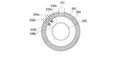
図20は、従来の縦型基板処理装置の処理炉の構成を示す概略図である。係る処理炉は、例えば石英(SiO2)で形成された反応管203’を備えている。反応管203’内には、処理室201’が形成されている。処理室201’内には、基板としてのウエハ(図示せず)を複数枚多段に支持する基板保持具としてのボート(図示せず)が搬入されるように構成されている。処理炉は、処理室201’内に原料ガスや酸化ガス等の処理ガスを供給するガス供給ユニットを備えている。ガス供給ユニットは、原料ガス(例えばZr元素を含むガス)を供給する第1のガス供給管232a’と、酸化ガス(例えばオゾン(O3)ガス)を供給する第2のガス供給管232b’と、第1のガス供給管232a’に接続された第1のガス供給ノズル233a’と、第2のガス供給管232b’に接続された第2のガス供給ノズル233b’と、を備えている。第1のガス供給ノズル233a’及び第2のガス供給ノズル233b’は、それぞれ反応管203’内に設けられており、反応管203’の内壁に沿って反応管203’内の下部から反応管203’の天井部に付近に及んで垂直に延在するように構成されている。第1のガス供給ノズル233a’及び第2のガス供給ノズル233b’には、それぞれ複数のガス噴出口が設けられている。ガス噴出口の配列ピッチは、上述のボート(図示せず)に多段に支持されている複数のウエハ(図示せず)の支持ピッチと、同じになるように構成されている。ガス噴出口は、処理ガスを各ウエハの上面に沿わせて流すことができるように構成されている。また、第1のガス供給管232a’は、バルブ243a’を介して、原料ガスを供給する原料ガス供給源と接続されている。第2のガス供給管232b’は、バルブAV2’を介して、酸化ガスを供給する酸化ガス供給源と接続されている。なお、図示しないが、処理炉は、処理室201’内にキャリアガス(パージガス)としてのN2ガスを供給するキャリアガスラインと、処理室201’内の雰囲気を排気する排気ユニットと、を更に備えている。FIG. 20 is a schematic view showing a configuration of a processing furnace of a conventional vertical substrate processing apparatus. Such a processing furnace includes a
例えばALD法を用いた基板処理工程では、第1の原料ガス供給工程→N2パージ工程→第1の排気工程→第2の原料供給工程→N2パージ工程→第2の排気工程を1サイクルとしてこのサイクルを複数繰り返す。第1の原料ガス供給工程では、排気ユニット(図示せず)により処理室201’内を排気しながら、バルブAV2’を閉とし、バルブ243a’を開とし、処理室201’内へ原料ガスを供給する。これにより、第1のガス供給ノズル233a’の各ガス噴出口から噴出される原料ガスが、各ウエハ上を水平に流れ、ウエハの表面に吸着し、ウエハ上に下地膜が形成される。N2パージ工程では、排気ユニット(図示せず)による処理室201’内の排気を継続しながら、バルブAV2’、バルブ243a’を閉とし、キャリアガスライン(図示せず)から処理室201’内にパージガスとしてのN2ガスを供給する。これにより、処理室201’内に残留している原料ガスが処理室201’内から排出され、処理室201’内がパージされる。第1の排気工程で
は、排気ユニット(図示せず)による処理室201’内の排気を継続しながら、バルブAV2’、バルブ243a’を閉としつつ、キャリアガスライン(図示せず)からのN2ガスの供給を停止する。これにより、処理室201’内が排気されて清浄化される。酸化ガス供給工程では、排気ユニット(図示せず)による処理室201’内の排気を継続しながら、バルブ243a’を閉、バルブAV2’を開とし、処理室201’内へ酸化ガスとしてのO3ガスを供給する。これにより、第2のガス供給ノズル233b’の各ガス噴出口から噴出される酸化ガスが、各ウエハ上を水平に流れ、ウエハ上に形成されている下地膜と反応し、ウエハ上に酸化膜が形成される。For example, in the substrate processing process using the ALD method, the first source gas supply process → N2 purge process → first exhaust process → second source supply process → N2 purge process → second exhaust process is one cycle. Repeat this cycle multiple times. In the first source gas supply step, while exhausting the inside of the
このように、ALD法やCVD法では、酸化種である第2の原料として例えばオゾンを含む酸化ガスを用い、オゾンを各ウエハの上面に沿わせて水平に供給するようにしている。しかし、従来の縦型基板処理装置で処理を行うと、オゾンが一番供給されやすいウエハ外周側での酸化が進み易く、オゾンが一番供給され難いウエハ中央側での酸化が遅れ易いという傾向があった。そのため、ウエハの面内における酸化膜の膜厚分布や組成分布が悪化してしまい、半導体装置の特性にバラツキが発生し、半導体装置の製造歩留りが悪化してしまう場合があった。 As described above, in the ALD method or the CVD method, for example, an oxidizing gas containing ozone is used as the second raw material that is an oxidizing species, and ozone is supplied horizontally along the upper surface of each wafer. However, when processing is performed using a conventional vertical substrate processing apparatus, oxidation tends to proceed on the wafer outer peripheral side where ozone is most easily supplied, and oxidation tends to be delayed on the wafer center side where ozone is hardly supplied. was there. For this reason, the film thickness distribution and composition distribution of the oxide film in the surface of the wafer are deteriorated, the characteristics of the semiconductor device are varied, and the manufacturing yield of the semiconductor device is sometimes deteriorated.
そこで、次の二つの方法の検討が試みられてきた。ひとつは、ウエハ上でのオゾンを含む酸化ガスの流速を増加させることにより、ウエハ中央部での酸化遅れを防止する方法である。他の一つは、ウエハ上にオゾンを高密度に含んだ酸化ガスを大流量で供給することにより、ウエハ全体の酸化むらをなくし、面内均一に処理する方法である。 Then, examination of the following two methods has been tried. One is a method of preventing the oxidation delay at the center of the wafer by increasing the flow rate of the oxidizing gas containing ozone on the wafer. The other is a method in which an oxidation gas containing ozone at a high density is supplied onto the wafer at a high flow rate so that the oxidation unevenness of the entire wafer is eliminated and the wafer is uniformly processed in the surface.
しかし、前者の方法では十分な改善は見られず、ウエハ中央部での酸化遅れを十分に防止することは難しく、半導体装置の製造歩留りを向上させることは困難であった。 However, the former method has not been improved sufficiently, and it has been difficult to sufficiently prevent the oxidation delay at the center of the wafer, and it has been difficult to improve the manufacturing yield of the semiconductor device.
また、後者の方法では歩留りを向上させることができるが、酸化ガス供給源が備えるオゾナイザ(図示しない)の性能上、一度に供給できる高密度のオゾンの流量が減少してしまい、オゾンの供給時間が長くなり、スループット(生産性)が悪化してしまう場合があった。 The latter method can improve the yield, but due to the performance of an ozonizer (not shown) provided in the oxidizing gas supply source, the flow rate of high-density ozone that can be supplied at one time decreases, and the ozone supply time. In some cases, the throughput (productivity) deteriorates.
本発明の目的は、基板上に酸化ガスを供給して酸化膜を形成する際に、処理時間を短縮し、面内膜厚の均一性を向上することにある。 An object of the present invention is to reduce the processing time and improve the uniformity of the in-plane film thickness when forming an oxide film by supplying an oxidizing gas onto a substrate.
本発明の一態様によれば、基板を収容した処理室内に原料ガスを供給する原料ガス供給工程と、前記処理室内に残留する前記原料ガスおよび前記原料ガスの中間体を除去する原料ガス除去工程と、前記処理室内の雰囲気の排気を実質的に止めた状態で、前記処理室内にオゾンを供給するオゾン供給工程と、前記処理室内に残留する前記オゾンおよび前記オゾンの中間体を除去するオゾン除去工程と、を複数回繰り返して前記原料ガスと前記オゾンとを互いに混合しないよう交互に供給し、前記基板の表面に酸化膜を形成する基板処理方法が提供される。 According to one aspect of the present invention, a source gas supply step for supplying a source gas into a processing chamber containing a substrate, and a source gas removal step for removing the source gas remaining in the processing chamber and an intermediate of the source gas. An ozone supply step for supplying ozone into the processing chamber in a state where the exhaust of the atmosphere in the processing chamber is substantially stopped, and ozone removal for removing the ozone remaining in the processing chamber and the intermediate of ozone The substrate processing method is provided in which the step is repeated a plurality of times to alternately supply the source gas and the ozone so as not to mix with each other, thereby forming an oxide film on the surface of the substrate.
本発明の他の態様によれば、基板を収容した処理室内に原料ガスを供給する工程と、前記処理室内の雰囲気を排気する工程と、前記処理室に接続されたガス溜り部内にオゾンを充填する工程と、前記処理室内に、前記ガス溜り部内に充填された前記オゾンを供給する工程と、前記処理室内の雰囲気を排気する工程と、を複数回行って前記原料ガスと前記オゾンとを互いに混合しないように交互に供給し、前記基板の表面に酸化膜を形成する基板処理方法が提供される。 According to another aspect of the present invention, the step of supplying a source gas into a processing chamber containing a substrate, the step of exhausting the atmosphere in the processing chamber, and filling a gas reservoir connected to the processing chamber with ozone A step of supplying the ozone filled in the gas reservoir into the processing chamber, and a step of exhausting the atmosphere in the processing chamber a plurality of times, and the source gas and the ozone are mutually exchanged. A substrate processing method is provided in which the oxide film is formed on the surface of the substrate by alternately supplying them so as not to be mixed.
本発明のさらに他の態様によれば、基板を処理室内に搬入する基板搬入工程と、前記処理室内の雰囲気の排気を実質的に止めた状態で、前記処理室内にオゾンを供給するオゾン供給工程と、前記処理室内に残留する前記オゾンおよび前記オゾンの中間体を除去するオゾン除去工程と、を有し、前記オゾン供給工程と前記オゾン除去工程とを複数回繰り返し、前記基板の表面に酸化膜を形成する基板処理方法が提供される。 According to still another aspect of the present invention, a substrate carrying-in step for carrying a substrate into the processing chamber, and an ozone supply step for supplying ozone into the processing chamber in a state where the exhaust of the atmosphere in the processing chamber is substantially stopped. And an ozone removal step for removing the ozone remaining in the processing chamber and the intermediate of ozone, and repeating the ozone supply step and the ozone removal step a plurality of times, and forming an oxide film on the surface of the substrate A substrate processing method is provided.
本発明のさらに他の態様によれば、基板を収容した処理室に接続されたガス溜り部内にオゾンを充填する工程と、前記処理室内に、前記ガス溜り部内に充填された前記オゾンを供給する工程と、前記処理室内の雰囲気を排気する工程と、を複数繰り返して、前記基板の表面に酸化膜を形成する基板処理方法が提供される。 According to still another aspect of the present invention, a step of filling ozone in a gas reservoir connected to a processing chamber containing a substrate, and supplying the ozone filled in the gas reservoir into the processing chamber. There is provided a substrate processing method in which an oxide film is formed on the surface of the substrate by repeating a plurality of steps and a step of exhausting the atmosphere in the processing chamber.
本発明のさらに他の態様によれば、基板を処理する処理室と、前記処理室内にオゾンを供給するガス供給ユニットと、前記処理室内の雰囲気を排気する排気ユニットと、制御部と、を有し、前記ガス供給ユニットは、前記処理室と接続されたオゾン供給路と、前記オゾン供給路の開閉を行うオゾン供給バルブと、を備え、前記排気ユニットは、前記処理室と接続された排気路と、前記排気路を開閉する排気バルブと、を備え、前記制御部は、前記オゾンを前記処理室内に供給するときは、前記処理室内の雰囲気の排気を実質的に止めた状態で前記オゾン供給路から前記オゾンを前記処理室内に供給するように前記ガス供給ユニットおよび前記排気ユニットを制御する基板処理装置が提供される。 According to still another aspect of the present invention, there is provided a processing chamber for processing a substrate, a gas supply unit for supplying ozone into the processing chamber, an exhaust unit for exhausting an atmosphere in the processing chamber, and a control unit. The gas supply unit includes an ozone supply path connected to the processing chamber and an ozone supply valve for opening and closing the ozone supply path, and the exhaust unit is an exhaust path connected to the processing chamber. And an exhaust valve that opens and closes the exhaust passage, and when the ozone is supplied into the processing chamber, the controller supplies the ozone in a state where the exhaust of the atmosphere in the processing chamber is substantially stopped. There is provided a substrate processing apparatus for controlling the gas supply unit and the exhaust unit so as to supply the ozone into the processing chamber from a passage.
本発明によれば、基板上に酸化ガスを供給して酸化膜を形成する際に、処理時間を短縮し、面内膜厚の均一性を向上させることができる。 According to the present invention, when an oxide gas is formed on a substrate by forming an oxide film, the processing time can be shortened and the uniformity of the in-plane film thickness can be improved.
<第1の実施形態>
まず、本発明の第1の実施形態に係るノーマルフロー方式の縦型基板処理装置の基本構成、及び該基板処理装置により実施される基板処理方法について説明する。<First Embodiment>
First, a basic configuration of a normal flow type vertical substrate processing apparatus according to a first embodiment of the present invention and a substrate processing method performed by the substrate processing apparatus will be described.
(1)基板処理装置の構成
図1は、本実施形態に係る基板処理装置の全体構成を示す概略構成図である。図示されるように、基板処理装置101は、筐体111を備えている。シリコン等からなるウエハ(基板)200を筐体111内外へ搬送するには、シリコン等からなるウエハ(基板)200を収納したウエハキャリアとしてのカセット110が使用される。基板処理装置101の筐体111の正面壁111aの下方には、筐体111内をメンテナンス可能なように開口された開口部としての正面メンテナンス口(図示せず)が開設されている。筐体111の正面壁111aには、この正面メンテナンス口を開閉する正面メンテナンス扉(図示せず)が建て付けられている。メンテナンス扉には、カセット搬入搬出口(基板収容器搬入搬出口)112が、筐体111内外を連通するように開設されている。カセット搬入搬出口112は、フロントシャッタ(基板収容器搬入搬出口開閉機構)113によって開閉されるようになっている。カセット搬入搬出口112の筐体111内側には、カセットステージ(基板収容器受渡し台)114が設置されている。カセット110は、カセットステージ114上に工程内搬送装置(図示せず)によって搬入され、かつまた、カセットステージ114上から搬出されるようになっている。(1) Configuration of Substrate Processing Apparatus FIG. 1 is a schematic configuration diagram showing the overall configuration of a substrate processing apparatus according to this embodiment. As illustrated, the
カセット110は、図示しない工程内搬送装置によって、カセット110内のウエハ200が垂直姿勢となり、カセット110のウエハ出し入れ口が上方向を向くように、カセットステージ114上に載置される。カセットステージ114は、カセット110を筐体111の後方に向けて縦方向に90°回転させ、カセット110内のウエハ200を水平姿勢とさせ、カセット110のウエハ出し入れ口を筐体111内の後方を向かせることが可能なように構成されている。 The
筐体111内の前後方向の略中央部には、カセット棚(基板収容器載置棚)105が設置されている。カセット棚105には、複数段、複数列にて複数個のカセット110が保管されるように構成されている。カセット棚105には、後述するウエハ移載機構125の搬送対象となるカセット110が収納される移載棚123が設けられている。また、カセットステージ114の上方には、予備カセット棚107が設けられ、予備的にカセット110を保管するように構成されている。 A cassette shelf (substrate container mounting shelf) 105 is installed at a substantially central portion in the front-rear direction in the
カセットステージ114とカセット棚105との間には、カセット搬送装置(基板収容器搬送装置)118が設置されている。カセット搬送装置118は、カセット110を保持したまま昇降可能なカセットエレベータ(基板収容器昇降機構)118aと、カセット110を保持したまま水平移動可能な搬送機構としてのカセット搬送機構(基板収容器搬送機構)118bと、を備えている。これらカセットエレベータ118aとカセット搬送機構118bとの連続動作により、カセットステージ114、カセット棚105、予備カセット棚107との間で、カセット110を搬送するように構成される。 A cassette carrying device (substrate container carrying device) 118 is installed between the
カセット棚105の後方には、ウエハ移載機構(基板移載機構)125が設置されている。ウエハ移載機構125は、ウエハ200を水平方向に回転ないし直動可能なウエハ移載装置(基板移載装置)125aと、ウエハ移載装置125aを昇降させるウエハ移載装置エレベータ(基板移載装置昇降機構)125bと、を備えている。なお、ウエハ移載装置125aは、ウエハ200を水平姿勢で保持するツイーザ(基板移載用治具)125cを備えている。ウエハ移載装置エレベータ125bは、耐圧性を有する筐体111の右側端部に設置されている。これら、ウエハ移載装置125aとウエハ移載装置エレベータ125bとの連続動作により、ウエハ200を移載棚123上のカセット110内からピックアップして後述するボート(基板支持部材)217へ装填(チャージング)したり、ウエハ200をボート217から脱装(ディスチャージング)して移載棚123上のカセット110内へ収納したりするように構成されている。 A wafer transfer mechanism (substrate transfer mechanism) 125 is installed behind the
筐体111の後部上方には、処理炉202が設けられている。処理炉202の下端部には開口(炉口)が設けられている。係る開口は、炉口シャッタ(炉口開閉機構)147により開閉されるように構成されている。なお、処理炉202の構成については後述する。 A
処理炉202の下方には、ボート217を昇降させて処理炉202内外へ搬送する昇降機構としてのボートエレベータ(基板保持具昇降機構)115が設けられている。ボートエレベータ115の昇降台には、連結具としてのアーム128が設けられている。アーム128上には、ボート217を垂直に支持するとともに、ボートエレベータ115によりボート217が上昇したときに処理炉202の下端部を気密に閉塞する蓋体としてのシールキャップ219が水平に設けられている。 Below the
ボート217は複数本の保持部材を備えており、複数枚(例えば、50枚〜150枚程度)のウエハ200を、その中心を揃えて垂直方向に整列させた状態で、それぞれ水平に保持するように構成されている。 The
カセット棚105の上方には、供給ファンと防塵フィルタとを備えたクリーンユニット134aが設けられている。クリーンユニット134aは、清浄化した雰囲気であるクリーンエアを筐体111の内部に流通させるように構成されている。 Above the
また、ウエハ移載装置エレベータ125bおよびボートエレベータ115側と反対側である筐体111の左側端部には、クリーンエアを供給するよう供給ファンと防塵フィルタとを備えたクリーンユニット134bが設置されている。クリーンユニット134bから吹き出されたクリーンエアは、ウエハ移載装置125a及びボート217の周囲を流通した後に、図示しない排気装置に吸い込まれて、筐体111の外部に排気されるようになっている。 In addition, a
(2)基板処理装置の動作
次に、本実施形態に係る基板処理装置101の動作について説明する。(2) Operation of Substrate Processing Apparatus Next, the operation of the
カセット110がカセットステージ114に供給されるに先立って、カセット搬入搬出口112がフロントシャッタ113によって開放される。その後、カセット110はカセット搬入搬出口112から搬入される。カセット110は、ウエハ200が垂直姿勢となりカセット110のウエハ出し入れ口が上方向を向くように、カセットステージ114上に載置される。その後、カセット110は、カセットステージ114によって、筐体111の後方に向けて縦方向に90°回転させられる。その結果、カセット110内のウエハ200は水平姿勢となり、カセット110のウエハ出し入れ口は筐体111内の後方を向く。 Prior to the
次に、カセット110は、カセット搬送装置118によって、カセット棚105ないし予備カセット棚107の指定された棚位置へ自動的に搬送されて受け渡されて一時的に保管された後、カセット棚105又は予備カセット棚107から移載棚123に移載されるか、もしくは移載棚123に直接搬送される。 Next, the
カセット110が移載棚123に移載されると、ウエハ200は、ウエハ移載装置125aのツイーザ125cによって、ウエハ出し入れ口を通じてカセット110からピックアップされ、ウエハ移載装置125aとウエハ移載装置エレベータ125bとの連続動作によって移載室124の後方にあるボート217に装填(チャージング)される。ボート217にウエハ200を受け渡したウエハ移載装置125aは、カセット110に戻り、次のウエハ200をボート217に装填する。 When the
予め指定された枚数のウエハ200がボート217に装填されると、炉口シャッタ147によって閉じられていた処理炉202の下端部が、炉口シャッタ147によって開放される。続いて、シールキャップ219がボートエレベータ115によって上昇されることにより、ウエハ200群を保持したボート217が処理炉202内へ搬入(ローディング)される。 When a predetermined number of
ローディング後は、処理炉202にてウエハ200に任意の処理が実施される。かかる処理については後述する。処理後は、上述の逆の手順で、ウエハ200およびカセット110は、上述の手順とは逆の手順で筐体111の外部へ払い出される。 After loading, arbitrary processing is performed on the
(3)処理炉の構成
次に、本実施形態に係る処理炉202の構成について説明する。(3) Configuration of Processing Furnace Next, the configuration of the
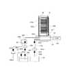
図2は、本実施形態に係る基板処理装置の処理炉202の縦断面図であり、図3は、図2に示す処理炉202のA−A線に対応する横断面図である。 2 is a longitudinal sectional view of the
(処理室) 本発明の一実施形態にかかる処理炉202は、反応管203とマニホールド209とを備えている。反応管203は、例えば石英(SiO2)や炭化珪素(SiC)等の耐熱性を有する非金属材料から構成され、上端部が閉塞され、下端部が開放された円筒形状となっている。マニホールド209は、例えばSUS等の金属材料から構成され、上端部及び下端部が開放された円筒形状となっている。反応管203は、マニホールド209により下端部側から縦向きに支持されている。反応管203とマニホールド209とは、同心円状に配置されている。マニホールド209の下端部は、上述したボートエレベータ115が上昇した際に、シールキャップ219により気密に封止されるように構成されている。マニホールド209の下端部とシールキャップ219との間には、処理室201内を気密に封止する封止部材としてのOリング220が設けられている。(Processing Chamber) A
反応管203の内部には、基板としてのウエハ200が収容される処理室201が形成されている。処理室201内には、基板保持具としてのボート217が下方から挿入され
るように構成されている。反応管203及びマニホールド209の内径は、ウエハ200を装填したボート217の最大外径よりも大きくなるように構成されている。Inside the
ボート217は、複数枚(例えば75枚から100枚)のウエハ200を、略水平状態で所定の隙間(基板ピッチ間隔)をもって多段に保持するように構成されている。ボート217は、ボート217からの熱伝導を遮断する断熱キャップ218上に搭載されている。断熱キャップ218は、回転軸255により下方から支持されている。回転軸255は、処理室201内の気密を保持しつつ、シールキャップ219の中心部を貫通するように設けられている。シールキャップ219の下方には、回転軸255を回転させる回転機構267が設けられている。回転機構267により回転軸255を回転させることにより、処理室201内の気密を保持したまま、複数のウエハ200を搭載したボート217を回転させることが出来るように構成されている。 The
反応管203の外周には、反応管203と同心円状に加熱手段(加熱機構)としてのヒータ207が設けられている。ヒータ207は、円筒形状であり、図3に示す保持板としてのヒータベース207aに支持されることにより垂直に据え付けられている。ウエハ200及び処理室内雰囲気は、ヒータ207からの輻射熱によって加熱される。 A
(ガス供給ユニット)
マニホールド209には、第1のガス供給ノズル233aが設けられている。第1のガス供給ノズル233aは、垂直部と水平部とを有するL字形状に構成されている。第1のガス供給ノズル233aの垂直部は、ウエハ200の積載方向に沿った直線状に形成されており、処理室201の下部から、反応管203の内壁とボート217上のウエハ200との間の平面視円弧状の空間内を通って、処理室201の天井部付近にまで延在されている。第1のガス供給ノズル233aの垂直部側面(筒部)には、処理室201内にガスを導入するガス導入口としての第1のガス噴出口248aが、鉛直方向に複数個設けられている。第1のガス噴出口248aは、ボート217に保持されるウエハ200の載置ピッチと同ピッチに設けられており、ボート217上の各ウエハ200の上面に沿わせてガスを水平に流すようにそれぞれ形成されている。また、第1のガス噴出口248aは、各ウエハ200上を流れるガスの流量を同一にするため、互いに同じ開口面積となっている。なお、第1のガス噴出口248aの開口径は、下部から上部にわたって徐々に大きくされていてもよい。(Gas supply unit)
The manifold 209 is provided with a first
第1のガス供給ノズル233aの水平部は、マニホールド209の側壁を貫通するように設けられている。第1のガス供給ノズル233aの上流端には、例えばHf(ハフニウム)元素やZr(ジルコニウム)元素を含むテトラキスエチルメチルアミノハフニウム(Hf[NCH3C2H5]4;TEHAH)やテトラキスエチルメチルアミノジルコニウム(TEMAZ)等の液体原料を気化させた原料ガス(TEHAHガスやTEMAZガス)を供給する第1のガス供給管232aが接続されている。第1のガス供給管232aには、上流から順に、図示しない液体原料供給源、流量制御装置(流量制御手段)である液体マスフローコントローラ240、液体原料を気化させて原料ガスを発生させる気化器242、及び第1のバルブ243aが設けられている。The horizontal portion of the first
第1のガス供給管232aの第1のバルブ243aの下流側には、キャリアガス(パージガス)としてのN2ガスを供給する第1のキャリアガス供給管234aが接続されている。第1のキャリアガス供給管234aには、上流から順に、図示しないキャリアガス供給源、流量制御装置(流量制御手段)である第2のマスフローコントローラ241b、第3のバルブ243cが設けられている。A first carrier
また、マニホールド209には、第2のガス供給ノズル233bが設けられている。第
2のガス供給ノズル233bは、垂直部と水平部とを有するL字形状に構成されている。第2のガス供給ノズル233bの垂直部は、ウエハ200の積載方向に沿った直線状に形成されており、処理室201の下部から、反応管203の内壁とボート217上のウエハ200との間の平面視円弧状の空間内を通って、処理室201の天井部付近にまで延在されている。第2のガス供給ノズル233bの垂直部側面(筒部)には、処理室201内にガスを導入するガス導入口としての第2のガス噴出口248bが、鉛直方向に複数個設けられている。第2のガス噴出口248bは、ボート217に保持されるウエハ200の載置ピッチと同ピッチに設けられており、ボート217上の各ウエハ200の上面に沿わせてガスを水平に流すようにそれぞれ形成されている。また、第2のガス噴出口248bは、各ウエハ200上を流れるガスの流量を同一にするため、互いに同じ開口面積となっている。なお、第2のガス噴出口248bの開口径は、下部から上部にわたって徐々に大きくされていてもよい。The manifold 209 is provided with a second
第2のガス供給ノズル233bの水平部は、マニホールド209の側壁を貫通するように設けられている。第2のガス供給ノズル233bの上流端には、酸化ガスであるオゾン(O3)ガスを供給する第2のガス供給管232bが接続されている。第2のガス供給管232bには、上流から順に、図示しないオゾンガス供給源、流量制御装置(流量制御手段)である第1のマスフローコントローラ241a、オゾン供給バルブAV2が設けられている。The horizontal portion of the second
第2のガス供給管232bの第1のマスフローコントローラ241aとオゾン供給バルブAV2との間には、ベントガス管232vが接続されている。ベントガス管232vには、第6のバルブ234vが設けられている。処理室201内へオゾンガスを供給しないときには、オゾンの生成を停止することなく、第6のバルブ234vを開けてベントガス管232vからオゾンを排出するようにすることで、次回の処理室201内へのオゾンの供給を安定かつ迅速に開始させることができる。 A
第2のガス供給管232bのオゾン供給バルブAV2の下流側には、キャリアガス(パージガス)としてのN2ガスを供給する第2のキャリアガス供給管234bが接続されている。第2のキャリアガス供給管234bには、上流から順に、図示しないキャリアガス供給源、流量制御装置(流量制御手段)である第3のマスフローコントローラ241c、第4のバルブ243dが設けられている。A second carrier
主に、第1のガス供給ノズル233a、第1のガス噴出口248a、第1のガス供給管232a、図示しない液体原料供給源、液体マスフローコントローラ240、気化器242、第1のバルブ243a、第1のキャリアガス供給管234a、第2のマスフローコントローラ241b、第3のバルブ243cにより、本実施形態に係る原料ガス供給ユニットが構成される。また、主に、第2のガス供給ノズル233b、第2のガス噴出口248b、第2のガス供給管232b、図示しないオゾンガス供給源、第1のマスフローコントローラ241a、オゾン供給バルブAV2、ベントガス管232v、第6のバルブ234v、第2のキャリアガス供給管234b、図示しないキャリアガス供給源、第3のマスフローコントローラ241c、第4のバルブ243dにより、本実施形態に係る酸化ガス供給ユニットが構成される。また、主に、原料ガス供給ユニット及び酸化ガス供給ユニットにより、処理室201内に原料ガス及び酸化ガスを供給するガス供給ユニットが構成される。 Mainly, the first
このように、基板処理装置101には、二種類のガス(原料ガス及び酸化ガス)を処理室201に供給するガス供給ユニットが設けられている。そして、処理室201内への二種類のガスの交互供給によって、ウエハ200上へ所望の膜を形成するように構成されている。また、成膜工程間で、キャリアガスによりパージした後、真空ポンプ246によっ
て排気することによって、処理室201内を清浄化するように構成されている。さらに、ガス供給ユニットの一部を処理に適した装置と交換することによって、所望の処理を実施できるようになっている。As described above, the
(排気ユニット)
マニホールド209の側壁には、排気管231が接続されている。排気管231には、上流側から順に、排気バルブとしての第5のバルブ243e、真空ポンプ246が設けられている。なお、第5のバルブ243eは、弁を開閉して処理室201の真空排気の開始・停止を制御でき、更に、弁開度を調節することにより処理室201内の圧力を調整可能な自動圧力調節弁(APCバルブ)として構成されている。主に、排気管231、第5のバルブ243e、真空ポンプ246により、処理室201内の雰囲気を排気する排気ユニットが構成される。(Exhaust unit)
An
(コントローラ)
本実施形態に係る基板処理装置は、制御部(制御手段)であるコントローラ280を備えている。コントローラ280は、液体マスフローコントローラ240、第1〜第3のマスフローコントローラ241a、241b、241c、第1〜第6のバルブ243a、243b、243c、243d、243e、243v、ヒータ207、真空ポンプ246、回転機構267、図示しないボート昇降機構に接続されている。コントローラ280は、液体マスフローコントローラ240及び第1〜第3のマスフローコントローラ241a、241b、241cの流量調整動作、第1〜第4及び第6のバルブ243a、243b、243c、243d、243vの開閉動作、第5のバルブ243eの開閉及び開度調整動作、ヒータ207の温度調整動作、真空ポンプ246の起動・停止、回転機構267の回転速度調整、ボート昇降機構の昇降動作をそれぞれ制御するように構成されている。(controller)
The substrate processing apparatus according to this embodiment includes a
(4)基板処理工程
次に、半導体デバイスの製造工程の一つとして実施される本実施形態に係る基板処理工程について説明する。本実施形態に係る基板処理工程は、上述の基板処理装置(ノーマルフロー方式の縦型基板処理装置)により実施される。以下の説明において、基板処理装置を構成する各部の動作は、コントローラ280により制御される。(4) Substrate Processing Step Next, the substrate processing step according to the present embodiment that is performed as one of the semiconductor device manufacturing steps will be described. The substrate processing process according to this embodiment is performed by the above-described substrate processing apparatus (normal flow type vertical substrate processing apparatus). In the following description, the operation of each part constituting the substrate processing apparatus is controlled by the
本実施形態に係る基板処理工程では、原料ガスとしてTEMAHガスを、酸化ガスとしてオゾンガスを用い、ALD法によりウエハ200上にHfO2膜を成膜する。CVD法の一つであるALD法は、ある成膜条件(温度、時間等)の下で、成膜に用いる少なくとも2種類の原料となる反応性ガスを1種類ずつ交互に基板上に供給し、1原子単位で基板上に吸着させ、表面反応を利用して成膜を行う手法である。このとき、膜厚の制御は、反応性ガスを供給するサイクル数で行う(例えば、成膜速度が1Å/サイクルとすると、20Åの膜を形成する場合、20サイクル行う)。ALD法を用いた成膜処理では、HfO、ZrOを成膜する際の処理温度は、180℃〜270℃、例えば250℃とする。ALD法では、例えばHfO2膜形成の場合、TEMAHガスとオゾンガスとを用いて180〜250℃の低温で高品質の成膜が可能である。In the substrate processing step according to the present embodiment, a TMAH gas is used as a source gas, an ozone gas is used as an oxidizing gas, and an HfO2 film is formed on the
(ウエハ搬入工程)
まず、上述したようにウエハ200をボート217に装填し、処理室201内に搬入する。ボート217を処理室201内に搬入した後、後述する4つのステップを順次実行する。(Wafer loading process)
First, as described above, the
(原料ガス供給工程(ステップ1))
ステップ1では、ウエハ200を収容した処理室201内の雰囲気を排気しつつ、処理室201内に原料ガスとしてのTEMAHガスを供給する。(Raw gas supply process (Step 1))
In
具体的には、排気管231の第5のバルブ243eを開け、処理室201内の雰囲気の排気を開始する。そして、第1のキャリアガス供給管234aの第3のバルブ243cを開け、キャリアガスとしてのN2ガスを、第2のマスフローコントローラ241bにより流量調整しながら、第1のガス供給管232aへと流す。また、液体原料としてのTEMAHを、液体マスフローコントローラ240により流量調整しつつ、図示しない液体原料供給源から気化器242へと流して気化させ、TEMAHガスを発生させる。そして、第1のガス供給管232aの第1のバルブ243aを開け、気化器242にて発生させたTEMAHガスを、第1のガス供給ノズル233aに向けて流す。TEMAHガスは、第1のガス供給管232a内でキャリアガスと混合する。TEMAHガスとキャリアガスとの混合ガスは、第1のガス供給ノズル233aの第1のガス噴出口248aを介して、処理室201内に供給される。処理室201内に供給された混合ガス中のTEMAHは、ウエハ200の表面部分等と表面反応(化学吸着)し、ウエハ200上に下地膜が形成される。下地膜の形成に寄与しない混合ガスの余剰分は、排気ガスとして排気管231から排気される。Specifically, the
この時、第5のバルブ243eの開度を、処理室201内の圧力が0.1〜400Paの範囲であって、例えば200Paに維持されるように設定する。また、液体マスフローコントローラ240が制御するTEMAHの流量を0.01〜0.1g/minとし、混合ガスにウエハ200を晒す時間を30〜180秒間とする。また、ヒータ207の温度を、ウエハ200の温度が180〜250℃の範囲であって、例えば230℃になるように設定する。 At this time, the opening degree of the
(原料ガス除去工程(ステップ2))
ステップ2では、処理室201内に残留するTEMAHガスおよびTEMAHガスの中間体を除去する。(Raw material gas removal process (step 2))
In
具体的には、第1のガス供給管232aの第1のバルブ243aを閉め、処理室201内へのTEMAHガスの供給を停止する。このとき、排気管231の第5のバルブ243eは開いたままとし、真空ポンプ246により処理室201内を20Pa以下となるまで排気し、残留TEMAHガスおよびTEMAHガスの中間体を処理室201内から排除する。なお、処理室201内からの残留TEMAHガスおよびTEMAHガスの中間体の除去が完了するまでは、第1のキャリアガス供給管234aの第3のバルブ243cを開けておき、第2のマスフローコントローラ241bにより流量調整しながらパージガスとしてのN2を処理室201内へ供給するようにすれば、処理室201内から残留TEMAHガスおよびTEMAHガスの中間体を排除する効果が更に高まる。Specifically, the
(オゾン供給工程(ステップ3))
ステップ3では、処理室201内の雰囲気の排気を実質的に止めた状態で、処理室201内にオゾンを供給する。(Ozone supply process (step 3))
In
具体的には、排気管231の第5のバルブ243eを閉めることにより、処理室201内の排気を実質的に止める。そして、第2のキャリアガス供給管234bの第4のバルブ243dを開け、キャリアガスとしてのN2ガスを、第3のマスフローコントローラ241cにより流量調整しながら、第2のガス供給管232bへと流す。また、第2のガス供給管232bのオゾン供給バルブAV2を開け、酸化ガスとしてのオゾンガスを、第1のマスフローコントローラ241aにより調整しながら、第2のガス供給ノズル233bに向けて流す。オゾンガスは、第2のガス供給管232b内でキャリアガスと混合する。オゾンガスとキャリアガスとの混合ガスは、第2のガス供給ノズル233bの第2のガス噴出口248bを介して、処理室201内に供給される。処理室201内に供給された混合
ガス中のオゾンは、ウエハ200の表面に化学吸着しているTEMAHと表面反応し、ウエハ200上にHfO2膜が成膜される。HfO2膜の形成に寄与しない混合ガスの余剰分は、排気ガスとして排気管231から排気される。Specifically, the exhaust in the
この時、第5のバルブ243eの開度を、処理室201内の圧力を0.1〜400Paの範囲であって、例えば200Paに維持する圧力に設定する。また、O3にウエハ200を晒す時間を、10〜120秒間に設定する。また、ヒータ207の温度を、ウエハ200の温度がステップ1のTEMAHガスの供給時と同じく180〜250℃の範囲であって、例えば230℃となるように設定する。At this time, the opening degree of the
(繰り返し工程)
その後、上述したステップ1〜4を1サイクルとし、このサイクルを複数回繰り返すことにより、ウエハ200上に所定の膜厚のHfO2膜を成膜し、本実施形態に係る基板処理工程を終了する。そして、ウエハ搬入工程と逆の手順により、処理室201内から処理後のウエハ200を搬出する。(Repeated process)
Thereafter, steps 1 to 4 described above are defined as one cycle, and this cycle is repeated a plurality of times to form a HfO2 film having a predetermined film thickness on the
(5)本実施形態に係る効果
本実施形態によれば、以下に示す1つ又は複数の効果を奏する。(5) Effects according to the present embodiment According to the present embodiment, the following one or more effects are achieved.
(a)本実施形態によれば、処理室201内にオゾンを供給するオゾン供給工程(ステップ3)を、処理室201内の雰囲気の排気を実質的に止めた状態で行う。これにより、処理室201内にオゾンを充満及び拡散させ、ウエハ200の外縁部だけでなく中心部にもオゾンを十分に供給することができる。その結果、HfO2膜を形成する際の処理時間を短縮させ、ウエハ200上に形成されるHfO2膜の膜厚分布や組成分布の均一性を向上させることができる。(A) According to this embodiment, the ozone supply step (step 3) for supplying ozone into the
(b)また、本実施形態によれば、処理室201内にTEMAHガスとオゾンとを互いに混合しないよう交互に供給する。これにより、処理室201内における余分な気相反応を抑制し、ウエハ200上にて効率よく成膜反応を生じさせ、HfO2膜を形成する際の処理時間を短縮させることができる。また、処理室201内でのパーティクルの発生が抑制され、ウエハ200上に形成されるHfO2膜の膜厚分布や組成分布の均一性を向上させることができる。(B) Further, according to the present embodiment, the TEMAH gas and ozone are alternately supplied into the
(c)また、本実施形態によれば、オゾン供給工程(ステップ3)を処理室201内の雰囲気の排気を実質的に止めた状態で行うことにより上述の効果が得られ、処理室201内にオゾンを大流量で供給する必要がない。その為、オゾンの浪費を抑制し、基板処理のコストを低減させることができる。(C) Further, according to the present embodiment, the above-described effect can be obtained by performing the ozone supply step (step 3) in a state in which the exhaust of the atmosphere in the
<第2の実施形態>
次に、本発明の第2の実施形態に係るサイドフロー方式の縦型基板処理装置の基本構成、及び該基板処理装置を使用した基板処理方法について説明する。<Second Embodiment>
Next, a basic configuration of a side flow type vertical substrate processing apparatus according to a second embodiment of the present invention and a substrate processing method using the substrate processing apparatus will be described.
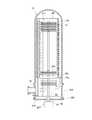
本実施形態に係る基板処理装置は、図18に例示するように、反応管203が、アウタチューブ31と、該アウタチューブ31内に配置されたインナチューブ38と、から構成されている点が、上述の実施形態に係る基板処理装置と異なる。また、インナチューブ38の側壁に複数の排気口41が設けられており、複数の該排気口41を通過した排気が、アウタチューブ31の下部に設けられた排気口35から排出される点が、上述の実施形態に係る基板処理装置と異なる。他の構成は、ノーマルフロー方式の縦型基板処理装置と同じである。 In the substrate processing apparatus according to the present embodiment, as illustrated in FIG. 18, the
以下、相違点を中心に、サイドフロー方式の縦型基板処理装置を説明する。 Hereinafter, a side flow type vertical substrate processing apparatus will be described focusing on the differences.
図18は、本実施形態に係るサイドフロー方式の処理炉の縦断面図である。図示されるように、本実施形態に係る反応管は、アウタチューブ31と、アウタチューブ31の内部に設置されたインナチューブ38と、から構成されている。アウタチューブ31及びインナチューブ38は、それぞれ、例えば石英(SiO2)や炭化珪素(SiC)等の耐熱性を有する非金属材料から構成され、上端部が閉塞され、下端部が開放された円筒形状となっている。アウタチューブ31は、マニホールド209により下端部側から縦向きに支持されている。アウタチューブ31の下部内壁表面には、内側に向かって突出する受台31aが形成されている。インナチューブ38の下部外壁表面には、外側に向かって突出する複数の突起部38aが形成されている。突起部38aが受台31a上に設置されることで、インナチューブ38はアウタチューブ31内に下方から縦向きに支持されるように構成されている。インナチューブ38外壁表面とアウタチューブ31内壁表面との間には、上下方向に連なる円筒状の間隙39が形成されている。インナチューブ38の内部には処理室201が形成され、ボート217が下方から挿入されるように構成されている。FIG. 18 is a longitudinal sectional view of a side flow type processing furnace according to the present embodiment. As shown in the figure, the reaction tube according to the present embodiment includes an
第1のガス供給ノズル233aの垂直部及び第2のガス供給ノズル233bの垂直部は、それぞれ、インナチューブ38の内壁とボート217上のウエハ200との間の平面視円弧状の空間内を通って、処理室201の天井部付近にまで延在されている。 The vertical portion of the first
インナチューブ38の側壁には、第1のガス供給ノズル233a及び第2のガス供給ノズル233bに対向した位置に、複数の排気口41が設けられている。複数の排気口41は、ボート217に保持されるウエハ200の載置ピッチ(すなわち第1のガス噴出口248aや第2のガス噴出口248bの配列ピッチ)と同ピッチに設けられており、ボート217上の各ウエハ200の上面に沿わせてガスを水平に流すように形成されている。なお、マニホールド209の側壁下方(インナチューブ38の下端下方)には、排気管231が接続される排気口35が形成されている。 On the side wall of the
また、マニホールド209の下端には、開口である炉口34が形成されている。炉口34は、炉口34の内径より大きな外径を有する円盤(蓋体)であるシールキャップ219によって、Oリング(シールリング)220を介してシールされるように構成されている。また、シールキャップ219の軸心部を貫通するように、回転機構267の回転軸64が設けられている。回転軸64の上端には支持台が垂直に立設されている。支持台上には基板保持具としてのボート217が垂直に立設されている。 A
複数のウエハ200を保持したボート217が処理室201内に挿入されて、処理室201がシールキャップ219によりシールされると、処理室201内は排気管231に接続された真空ポンプ246によって所定の圧力以下に排気され、ヒータ207への供給電力が上昇されることにより、処理室201内の温度が所定温度に昇温される。また、ボート217は、回転駆動機構63の回転軸62により回転させられる。ホットウォール式の炉構造として構成されていることにより、処理室201内の温度は全体にわたって均一に維持され、ボート217及びこれに保持された各ウエハ200の温度分布は全体にわたって均一になる。 When the
本実施形態によれば、上述の効果に加え、以下に示す1つ又は複数の効果を更に奏する。 According to this embodiment, in addition to the above-described effects, one or more effects described below are further exhibited.
(a)本実施形態によれば、第1のガス供給ノズル233a、第2のガス供給ノズル233bが、複数枚のウエハ200の積層方向に延在するように、インナチューブ38の内部に設けられている。さらに、複数の排気口41が、第1のガス供給ノズル233a、第2
のガス供給ノズル233bに対向したインナチューブ38の位置に設けられている。これにより、各ウエハ200に対して原料ガス及び酸化ガスの水平フローを形成することができる。そして、各ウエハ200上に形成するHfO2膜等の面内均一性を向上させることができる。(A) According to the present embodiment, the first
It is provided at the position of the
(b)また、本実施形態によれば、第1のガス供給ノズル233a、第2のガス供給ノズル233bが、ボート217に保持されたウエハ200の外縁に近接するように配置されている。これにより、ウエハ200への原料ガスや酸化ガスの供給効率を向上させることができ、基板処理の生産性を向上させることができる。また、ウエハ200中心付近へのガスの供給量を増大させることができ、ウエハ200上に形成されるHfO2膜の膜厚の面内均一性を向上させることができる。(B) According to the present embodiment, the first
(c)また、本実施形態によれば、インナチューブ38外壁表面とアウタチューブ31内壁表面との間に、上下方向に連なる間隙39が形成されている。また、排気口35が、インナチューブ38の開放端よりも下側に設けられている。これにより、インナチューブ38とアウタチューブ31との間の間隙39を通った後のガスと、インナチューブ38の開放端からのガスとの両方を同時に排気させることができ、ガスの置換効率を向上させることができる。(C) Further, according to the present embodiment, the
なお、図19は、図18に示したインナチューブ38の変形例を示す斜視図である。 FIG. 19 is a perspective view showing a modified example of the
図18で説明した基板処理装置との相違点は、排気口41Aがインナチューブ38の天井壁に開設されている点である。排気口41Aは、排気管231が設けられた側と反対側(複数の排気口41側)に設けられている。この変形例によれば、第1のガス供給ノズル233aの第1のガス噴出口248aから噴出されるガス、及び第2のガス供給ノズル233bの第2のガス噴出口248bから噴出されるガスの水平フローをそれぞれ抑制することができ、処理室201内のガスパージ効率を向上することができる。なお、排気口41Aの大きさは、水平フロー抑制効果とガスパージ効率とを比較して最適に設定することが望ましい。 A difference from the substrate processing apparatus described with reference to FIG. 18 is that an
<第3の実施形態>
次に、本発明の第3の実施形態に係る基板処理装置の構成、及び該基板処理装置により実施される基板処理工程について説明する。<Third Embodiment>
Next, a configuration of a substrate processing apparatus according to the third embodiment of the present invention and a substrate processing process performed by the substrate processing apparatus will be described.
(1)基板処理装置の構成
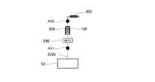
まず、本実施形態に係る基板処理装置の構成を、図4を参照しながら説明する。図4は、本実施形態に係る基板処理装置の処理炉及びガス供給ユニットの概略構成図である。本実施形態においては、ガス供給ユニットが、酸化ガスとしてのオゾンガスを処理室201内にパルス的に供給(フラッシュ供給)するように構成されている点が、上述の実施形態と異なる。なお、ガス供給ユニット以外の構成については、コントローラ280の酸化シーケンスを除き第1の実施形態と同様である。以下、本実施形態に係る基板処理装置のガス供給ユニットの構成について説明する。(1) Configuration of Substrate Processing Apparatus First, the configuration of the substrate processing apparatus according to the present embodiment will be described with reference to FIG. FIG. 4 is a schematic configuration diagram of a processing furnace and a gas supply unit of the substrate processing apparatus according to the present embodiment. The present embodiment is different from the above-described embodiment in that the gas supply unit is configured to supply ozone gas as an oxidizing gas into the
図4に示すように、第1のガス供給ノズル233aの上流端には、第1のガス供給管232aの下流端が接続されている。第1のガス供給管232aの上流端は、気化器242内に形成された気化室242aの2次側(アウトレット)に接続されている。気化室242aの1次側(インレット)には、搬送管100の下流端が接続されている。搬送管100の上流端は、液体原料供給源としてのタンク305内に貯留された液体原料としてのTEMAH内に挿入(浸漬)されている。搬送管100には、上流側から順に、バルブAV4、液体マスフローコントローラ240が設けられている。タンク305内に貯留された
TEMAHの上方空間には、圧送ガス供給管51の下流端が接続されており、圧送ガス供給管51から圧送ガスとしてのN2ガスが供給されるように構成されている。圧送ガス供給管51には、バルブAV3が設けられている。気化室242a内には、第1のキャリアガス供給管234aの下流端が接続されており、キャリアガス(パージガス)としてのN2ガスが供給されるように構成されている。第1のキャリアガス供給管234aには、上流側から順に、図示しないキャリアガス供給源、第2のマスフローコントローラ241b、第3のバルブ243cが設けられている。気化器242には切換弁50が設けられている。切換弁50は、タンク305内を気化室242aに連通させる切換位置(以下、原料ガス供給位置という)と、気化室242aを通じて第1のキャリアガス供給管234aと第1のガス供給管232aとを連通させる切換位置(以下、キャリアガス供給位置)とのいずれか一方に切換えることができるように構成されている。As shown in FIG. 4, the downstream end of the first
第2のガス供給ノズル233bの上流端には、第2のガス供給管232bの下流端が接続されている。第2のガス供給管232bには、上流側から順に、オゾン発生装置としてのオゾナイザ52、オゾン導入バルブAV1、第1のマスフローコントローラ241a、処理室201に接続されたガス溜り部としてのバッファタンク102、オゾン供給バルブAV2が設けられている。オゾナイザ52は、放電により酸素(O2)ガスからオゾンガスを生成する装置である。オゾナイザ52には、図示しない酸素ガス供給ラインから酸素ガスが供給されるように構成されている。ガス溜り部としてのバッファタンク102は、処理室201内にパルス的に供給するためのオゾンガスを一時的に充填する圧力容器として構成されている。すなわち、オゾナイザ52から供給されたオゾンガスが、バッファタンク102内に一時的に充填された後、処理室201内にパルス状に供給(フラッシュ供給)されるように構成されている。なお、本実施形態においては、第1の実施形態に係る基板処理装置と異なり、第2のキャリアガス供給管234bは取り外されている。The downstream end of the second
なお、気化器242において液体原料が気化されることで生成される原料ガスは、その種類によっては再液化しやすい場合がある。そのため、気化器242の2次側(アウトレット)から処理室201に至るまでの原料ガスの供給経路(第1のガス供給管232a、第1のガス供給ノズル233aの上流側)を、所定温度(例えば液体原料としてTEMAZを使用する場合は130℃)に加熱して、原料ガスの再液化を抑制するようにしている。具体的には、上述の原料ガスの供給経路(第1のガス供給管232a、第1のガス供給ノズル233aの上流側)の外表面に、リボンヒータ(図示しない)等を設けている。 Note that the raw material gas generated by vaporizing the liquid raw material in the
また、気化器242における液体原料の気化を促進させるため、タンク305から気化器242に至るまでの液体原料の供給経路(搬送管100)を所定温度に加熱して、気化器242に供給される液体原料を予熱するようにしている。具体的には、上述の液体原料の供給経路(搬送管100)の外表面に、リボンヒータ(図示しない)等を設けている。 Further, in order to promote the vaporization of the liquid raw material in the
なお、液体原料や原料ガスの供給経路(搬送管100、第1のガス供給管232a、第1のガス供給ノズル233aの上流側)の外表面にリボンヒータ(図示しない)を設けて該供給経路の内部を加熱するようにすると、熱伝導によって、バッファタンク102内までもが加熱されてしまい、バッファタンク102内に充填されたオゾンが分解してしまう場合がある。そのため、バッファタンク102内を冷却するようにしている。例えば、図15に示すように、バッファタンク102の外面には冷却コイル300を設け、冷却コイル300内にチラー水、工業用水等の熱交換媒体を流すことによって、バッファタンク102を冷却するようにしている。なお、図16に示すように、バッファタンク102を恒温槽301の内部に設けることとし、恒温槽301の内部を−20〜+25℃の範囲内、例えば23℃前後に温度を保つようにしてもよい。また、図示しないが、バッファタンク102をペルチェ素子によって冷却してもよい。このように構成することで、処理室201に至る前にバッファタンク102内でオゾンが分解されてしまうことを抑制でき、処理
室201内へのオゾンガスの供給を安定させ、オゾンの浪費を抑制することが可能となる。It should be noted that a ribbon heater (not shown) is provided on the outer surface of the liquid source or source gas supply path (the upstream side of the
また、バッファタンク102内に充填されたオゾンは、バッファタンク102の内壁面と反応し、失活してしまう場合がある。このため、バッファタンク102の内壁面をコーティング膜によりコートして、バッファタンク102の内壁面とオゾンガスとの反応を抑制するようにしている。コーティング膜種としては、例えば鉄(Fe)、チタン(Ti)、アルミ(Al)、ニッケル(Ni)又はクロム(Cr)等の酸化膜(Fe酸化膜、Ti酸化膜、AI酸化膜、Ni酸化膜、Cr酸化膜)を用いることができる。また、SUS316等のステンレス膜をバッファタンク102の内面にコーティングするか、又はバッファタンク102をSUS316等のステンレス鋼で構成してもよい。クロムを含むステンレス鋼は、酸化処理により酸化クロム等が形成されやすく、安定な不動膜(酸化膜)を形成するので、バッファタンク102内に充填されたオゾンの失活を防止することができる。 Further, the ozone filled in the
また、バッファタンク102の内壁面だけでなく、その他のオゾンガスの供給路、すなわち、第2のガス供給管232bの内壁面におけるオゾンの失活を抑制するようにしている。具体的には、第2のガス供給管232bの内壁面を上述のコーティング膜によりコーティングしている。なお、第2のガス供給管232bをステンレスで構成して、第2のガス供給管232bの内壁面に酸化クロム等から成る不動膜を形成するようにしてもよい。 Further, not only the inner wall surface of the
なお、ステンレス鋼で構成されたバッファタンク102の内壁面や第2のガス供給管232bの内壁面等に酸化クロム等から成る不動膜を形成するには、バッファタンク102や第2のガス供給管232bの内部の水分を十分除去した状態で、オゾナイザ52から第2のガス供給管232bにオゾンを供給するコーティング工程を実施すればよい。このとき、オゾン導入バルブAV1、オゾン供給バルブAV2を開、他のバルブは閉とする。その結果、ステンレスで構成された各部表面がオゾンに暴露されて酸化され、これらの表面に酸化クロム等の安定な不動膜が形成される。これによりオゾンの失活を抑制することができると共に、オゾンの無駄な消費を防止できる。なお、バッファタンク102の内壁面や第2のガス供給管232bの内壁面等に酸化クロム等から成る不動膜を形成するコーティング工程は、後述する基板処理工程を開始する前に行うようにしてもよい。 In order to form an immobile film made of chromium oxide or the like on the inner wall surface of the
(2)基板処理工程
次に、半導体デバイスの製造工程の一つとして実施される本実施形態に係る基板処理工程について説明する。本実施形態に係る基板処理工程は、オゾン供給工程の前に、処理室201に接続されたバッファタンク102内にオゾンを充填するオゾン充填工程を有し、オゾン供給工程では、バッファタンク102内に充填されたオゾンを処理室201内にパルス的に供給(フラッシュ供給)する点が、第1及び第2の実施形態と異なる。なお、本実施形態においては、オゾン充填工程とオゾン供給工程とオゾン除去工程とを複数繰り返すようにしている。本実施形態に係る基板処理工程は、図4に示す基板処理装置により実施される。以下の説明において、基板処理装置を構成する各部の動作は、コントローラ280により制御される。(2) Substrate Processing Step Next, the substrate processing step according to this embodiment that is performed as one of the semiconductor device manufacturing steps will be described. The substrate processing process according to the present embodiment includes an ozone filling process for filling ozone in the
(ウエハ搬入工程)
まず、上述したようにウエハ200をボート217に装填し、処理室201内に搬入する。ボート217を処理室201内に搬入した後、後述する5つのステップを順次実行する。(Wafer loading process)
First, as described above, the
(原料ガス供給工程(ステップ1))
ステップ1では、ウエハ200を収容した処理室201内の雰囲気を排気しつつ、処理
室201内に原料ガスとしてのTEMAHガスを供給する。(Raw gas supply process (Step 1))
In
具体的には、排気管231の第5のバルブ243eを開け、処理室201内の雰囲気の排気を開始する。また、バルブAV3を開け、タンク305内に貯留されたTEMAHの上方空間に、圧送ガスとしてのN2ガスを供給する。また、切換弁50を原料ガス供給位置とし、バルブAV4を開け、タンク305内に貯留されたTEMAHを、液体マスフローコントローラ240により流量調整しつつ、気化器242(気化室242a)へ圧送して気化させて、TEMAHガスを発生させる。また、第1のガス供給管232aの第1のバルブ243aを開け、キャリアガスとしてのN2ガスを、第2のマスフローコントローラ241bにより流量調整しながら、気化器242(気化室242a)へ供給する。その結果、TEMAHガスとキャリアガスとの混合ガスが、第1のガス供給ノズル233aの第1のガス噴出口248aを介して、処理室201内に供給される。処理室201内に供給された混合ガス中のTEMAHは、ウエハ200の表面部分等と表面反応(化学吸着)し、ウエハ200上に下地膜が形成される。下地膜の形成に寄与しない混合ガスの余剰分は、排気ガスとして排気管231から排気される。Specifically, the
この時、第5のバルブ243eの開度を、処理室201内の圧力が0.1〜400Paの範囲であって、例えば200Paに維持されるように設定する。また、液体マスフローコントローラ240が制御するTEMAHの流量を0.01〜0.1g/minとし、混合ガスにウエハ200を晒す時間を30〜180秒間とする。また、ヒータ207の温度を、ウエハ200の温度が180〜250℃の範囲であって、例えば230℃になるように設定する。 At this time, the opening degree of the
(原料ガス除去工程(ステップ2))
ステップ2では、処理室201内に残留するTEMAHガスおよびTEMAHガスの中間体を除去する。(Raw material gas removal process (step 2))
In
具体的には、気化器242の切換弁50をキャリアガス供給位置とし、処理室201内へのTEMAHガスの供給を停止する。このとき、排気管231の第5のバルブ243eは開いたままとし、真空ポンプ246により処理室201内を20Pa以下となるまで排気し、残留TEMAHガスおよびTEMAHガスの中間体を処理室201内から排除する。なお、処理室201内からの残留TEMAHガスおよびTEMAHガスの中間体の除去が完了するまでは、第1のキャリアガス供給管234aの第3のバルブ243cを開けておき、第2のマスフローコントローラ241bにより流量調整しながらパージガスとしてのN2を処理室201内へ供給するようにすれば、処理室201内から残留TEMAHガスおよびTEMAHガスの中間体を排除する効果が更に高まる。Specifically, the switching
(酸化膜形成工程(ステップ3))
次に、処理室201に接続されたガス溜り部としてのバッファタンク102内にオゾンを充填する工程(オゾン充填工程(ステップ3a))と、バッファタンク102内に充填されたオゾンを処理室201内に供給するオゾン供給工程(ステップ3b)と、処理室201の雰囲気を排気する工程(オゾン除去工程(ステップ3c))と、を複数繰り返す酸化膜形成工程(ステップ3)を実施する。(Oxide film forming step (step 3))
Next, a step of filling the
酸化膜形成工程(ステップ3)のシーケンス例1〜3を、図6〜図8にそれぞれ示す。 Sequence examples 1 to 3 of the oxide film forming step (step 3) are shown in FIGS.
(シーケンス例1)
図6は、酸化膜形成工程(ステップ3)のシーケンス例1を示す。(Sequence example 1)
FIG. 6 shows a sequence example 1 of the oxide film forming step (step 3).
シーケンス例1では、まず、図6の[1]に示すように、第5のバルブ(APC)24
3eを開、オゾン供給バルブAV2を閉とした状態で、オゾン導入バルブAV1を開とし、第1のマスフローコントローラ241aで流量調整しつつ、バッファタンク102内にオゾンガスを供給する(オゾン充填工程(ステップ3a))。In the sequence example 1, first, as shown in [1] of FIG. 6, the fifth valve (APC) 24 is used.
3e is opened and the ozone supply valve AV2 is closed, the ozone introduction valve AV1 is opened, and ozone gas is supplied into the
所定時間が経過し、バッファタンク102内に所定量のオゾンガスが充填され、バッファタンク102内の圧力が例えば100000Paに到達したら、図6の[2]に示すように、オゾン供給バルブAV2を開とし、バッファタンク102内に充填されていたオゾンガスを処理室201内に供給する(オゾン供給工程(ステップ3b))。オゾン供給工程(ステップ3b)においては、バッファタンク102内に充填されたオゾンガスが、処理室201内にパルス的に供給(フラッシュ供給)される。オゾンガスは、ウエハ200の表面に化学吸着しているTEMAHと表面反応し、ウエハ200上にHfO2膜が成膜される。なお、オゾン供給工程(ステップ3b)では、オゾンを供給した直後の処理室201内の圧力が例えば1〜1000Paの範囲内になるようにする。When a predetermined amount of time has passed and the
所定時間が経過したら、処理室201内に残留するオゾンおよびオゾンの中間体を除去する(オゾン除去工程(ステップ3c))。具体的には、第2のガス供給管232bのオゾン供給バルブAV2を閉め、処理室201内へのオゾンガスの供給を停止する。このとき、排気管231の第5のバルブ243eは開いたままとし、真空ポンプ246により処理室201内を20Pa以下となるまで排気し、残留オゾンおよびオゾンの中間体を処理室201内から排除する。なお、処理室201内からの残留オゾンおよびオゾンの中間体の除去が完了するまでは、第2のキャリアガス供給管234bの第4のバルブ243dを開けておき、第3のマスフローコントローラ241cにより流量調整しながらパージガスとしてのN2を処理室201内へ供給するようにすれば、処理室201内から残留オゾンおよびオゾンの中間体を排除する効果が更に高まる。When the predetermined time has elapsed, ozone remaining in the
そして、オゾン充填工程(ステップ3a)、オゾン供給工程(ステップ3b)、オゾン除去工程(ステップ3c)を1サイクルとしてこのサイクルを複数繰り返す。 The ozone filling process (step 3a), the ozone supplying process (step 3b), and the ozone removing process (step 3c) are set as one cycle, and this cycle is repeated a plurality of times.
(シーケンス例2)
図7は、酸化膜形成工程(ステップ3)のシーケンス例2を示す。シーケンス例2では、オゾン供給工程(ステップ3b)を実施する際に、処理室201内の排気を停止するようにしている。(Sequence example 2)
FIG. 7 shows a sequence example 2 of the oxide film forming step (step 3). In Sequence Example 2, the exhaust in the
シーケンス例2では、まず、図7の[1]に示すように、第5のバルブ(APC)243eを開、オゾン供給バルブAV2を閉とした状態で、オゾン導入バルブAV1を開とし、第1のマスフローコントローラ241aで流量調整しつつ、バッファタンク102内にオゾンガスを供給する(オゾン充填工程(ステップ3a))。 In sequence example 2, first, as shown in [1] of FIG. 7, in the state where the fifth valve (APC) 243e is opened and the ozone supply valve AV2 is closed, the ozone introduction valve AV1 is opened, and the first The ozone gas is supplied into the
所定時間が経過し、バッファタンク102内に所定量のオゾンガスが充填され、バッファタンク102内の圧力が例えば100000Paに到達したら、図7の[2]に示すように、第5のバルブ(APC)243eを閉、オゾン供給バルブAV2を開とし、バッファタンク102内に充填されていたオゾンガスを処理室201内に供給する(オゾン供給工程(ステップ3b))。オゾン供給工程(ステップ3b)においては、バッファタンク102内に充填されたオゾンガスが、処理室201内にパルス的に供給(フラッシュ供給)される。オゾンガスは、ウエハ200の表面に化学吸着しているTEMAHと表面反応し、ウエハ200上にHfO2膜が成膜される。なお、オゾン供給工程(ステップ4)では、オゾンを供給した直後の処理室201内の圧力が例えば1〜1000Paの範囲内になるようにする。When a predetermined amount of time elapses and the
その後、シーケンス例1と同様に、オゾン除去工程(ステップ3c)を実施する。そし
て、オゾン充填工程(ステップ3a)、オゾン供給工程(ステップ3b)、オゾン除去工程(ステップ3c)を1サイクルとしてこのサイクルを複数繰り返す。Thereafter, similarly to the sequence example 1, the ozone removing process (step 3c) is performed. The ozone filling process (step 3a), the ozone supplying process (step 3b), and the ozone removing process (step 3c) are set as one cycle, and this cycle is repeated a plurality of times.
(シーケンス例3)
図8は、酸化膜形成工程(ステップ3)のシーケンス例3を示す。シーケンス例3では、オゾン供給工程(ステップ4)を実施する際に、第5のバルブ(APC)243eの開度を調整し、処理室201内の圧力を平均圧力で調圧しつつ、処理室201内にオゾンガスを供給するようにしている。(Sequence example 3)
FIG. 8 shows a sequence example 3 of the oxide film forming step (step 3). In Sequence Example 3, when the ozone supply step (Step 4) is performed, the opening degree of the fifth valve (APC) 243e is adjusted, and the pressure in the
シーケンス例2では、まず、図8の[1]に示すように、第5のバルブ(APC)243eを開、オゾン供給バルブAV2を閉とした状態で、オゾン導入バルブAV1を開とし、第1のマスフローコントローラ241aで流量調整しつつ、バッファタンク102内にオゾンガスを供給する(オゾン充填工程(ステップ3a))。 In Sequence Example 2, first, as shown in [1] in FIG. 8, the ozone introduction valve AV1 is opened while the fifth valve (APC) 243e is opened and the ozone supply valve AV2 is closed. The ozone gas is supplied into the
所定時間が経過し、バッファタンク102内に所定量のオゾンガスが充填され、バッファタンク102内の圧力が例えば100000Paに到達したら、図8の[2]に示すように、第5のバルブ(APC)243eの開度を調整すると共に、オゾン供給バルブAV2を開とし、バッファタンク102内に充填されていたオゾンガスを処理室201内に供給する(オゾン供給工程(ステップ3b))。オゾン供給工程(ステップ3b)においては、バッファタンク102内に充填されたオゾンガスが、処理室201内にパルス的に供給(フラッシュ供給)される。オゾンガスは、ウエハ200の表面に化学吸着しているTEMAHと表面反応し、ウエハ200上にHfO2膜が成膜される。なお、オゾン供給工程(ステップ4)では、オゾンを供給した直後の処理室201内の圧力が例えば1〜1000Paの範囲内になるようにする。When a predetermined amount of time has elapsed and the
その後、シーケンス例1と同様に、オゾン除去工程(ステップ3c)を実施する。そして、オゾン充填工程(ステップ3a)、オゾン供給工程(ステップ3b)、オゾン除去工程(ステップ3c)を1サイクルとしてこのサイクルを複数繰り返す。 Thereafter, similarly to the sequence example 1, the ozone removing process (step 3c) is performed. The ozone filling process (step 3a), the ozone supplying process (step 3b), and the ozone removing process (step 3c) are set as one cycle, and this cycle is repeated a plurality of times.
なお、いずれのシーケンス例においても、少なくとも繰り返しの初回に行うオゾン充填工程(ステップ3a)は、上述の原料ガス供給工程(ステップ1)および/または原料ガス除去工程(ステップ2)と同時に行う。すなわち、原料ガス供給工程(ステップ1)と同時に行うか、原料ガス除去工程(ステップ2)と同時に行うか、もしくは、原料ガス供給工程(ステップ1)および原料ガス除去工程(ステップ2)と同時に行う。また、繰り返しの2回目に行うオゾン充填工程(ステップ3a)は、オゾン除去工程(ステップ3c)と同時に行うようにしても良い。すなわち、オゾン供給工程(ステップ3b)を実施した後、バッファタンク102内へのオゾンガスの充填を再開するタイミングは、オゾン供給工程(ステップ3b)の実行が完了した後とするのが好ましい。 In any of the sequence examples, the ozone filling process (step 3a) performed at least at the first repetition is performed simultaneously with the source gas supply process (step 1) and / or the source gas removal process (step 2). That is, it is performed simultaneously with the source gas supply process (step 1), simultaneously with the source gas removal process (step 2), or performed simultaneously with the source gas supply process (step 1) and the source gas removal process (step 2). . Further, the ozone filling process (step 3a) performed for the second repetition may be performed simultaneously with the ozone removing process (step 3c). That is, after the ozone supply process (step 3b) is performed, it is preferable that the timing at which the filling of the ozone gas into the
また、いずれのシーケンス例においても、ウエハ200を第1の温度(180〜250℃の範囲であって、例えば230℃)に加熱しつつ、バッファタンク102と処理室201とを接続する第2のガス供給管232bを第2の温度に加熱し、さらに、バッファタンク102を第3の温度に冷却する。このとき、第1の温度は第2の温度より高く、第2の温度は第3の温度より高くする。これにより、バッファタンク102内でオゾンが分解されてしまうことを抑制できる。 Further, in any sequence example, the second temperature that connects the
(繰り返し工程)
その後、上述した原料ガス供給工程(ステップ1)〜酸化膜形成工程(ステップ3)を1サイクルとし、このサイクルを複数回繰り返すことにより、ウエハ200上に所定の膜厚のHfO2膜を成膜し、本実施形態に係る基板処理工程を終了する。そして、ウエハ搬
入工程と逆の手順により、処理室201内から処理後のウエハ200を搬出する。(Repeated process)
Thereafter, the above-described source gas supply process (step 1) to oxide film formation process (step 3) are set as one cycle, and this cycle is repeated a plurality of times to form a HfO2 film having a predetermined thickness on the
なお、本実施形態において、処理室201に対するバッファタンク102の容積比は、例えば1/2100〜1/105とするとよい。例えば、処理室201の容積を210Lとすると、バッファタンク102の容積は0.1L〜2Lとするとよい。容積比が1/2100未満となると、処理室201内にパルス供給されるオゾンガスの流速が、バッファタンク102を用いない場合のオゾンガスの流速と同程度となってしまい、バッファタンク102を用いることによる効果が得られ難くなってしまうからである。また、容積比が1/105を超えると、バッファタンク102内から処理室201内へオゾンガスをパルス供給した際に、処理室201内の圧力が高くなりすぎてしまい、好ましくないからである。 In the present embodiment, the volume ratio of the
また、バッファタンク102内に充填するオゾンガスの圧力は200〜101,130Paの範囲内であって、例えば100000Paとするとよい。バッファタンク102に充填するオゾンガスの圧力が200Pa未満となると、処理室201内にパルス供給されるオゾンガスの流速が、バッファタンク102を用いない場合のオゾンガスの流速と同程度となってしまい、バッファタンク102を用いることによる効果が得られ難くなってしまうからである。また、バッファタンク102に充填するオゾンガスの圧力が101,130Paを超えると、バッファタンク102内から処理室201内へオゾンガスをパルス供給した際に、供給圧との差圧がとれず流量制御できなくなって、好ましくないからである。 Moreover, the pressure of the ozone gas with which the
またオゾン供給工程(ステップ3b)を実施中の処理室201内の圧力を0.1〜1000Paとするとよい。オゾン供給工程(ステップ3b)を実施中の処理室201圧力が0.1Pa未満となると、ウエハ200表面へのオゾン供給が不足してしまうことになるからである。また、オゾン供給工程(ステップ3b)を実施中の処理室201内の圧力が1000Pa以上となると、真空ポンプ246の排気速度が低下してしまうからである。 The pressure in the
(3)本実施形態に係る効果
本実施形態によれば、上述の効果に加え、以下に示す1つ又は複数の効果を更に奏する。(3) Effects according to this embodiment According to this embodiment, in addition to the above-described effects, one or more effects described below are further exhibited.
(a)本実施形態によれば、オゾン供給工程(ステップ3b)の前に、ガス溜り部としてのバッファタンク102内にオゾンを充填するオゾン充填工程(ステップ3a)を実施する。そして、オゾン供給工程(ステップ3b)では、バッファタンク102内に充填されたオゾンを処理室201内にパルス的に供給(フラッシュ供給)する。これにより、ウエハ200上へのオゾンの供給量が増加し、ウエハ200中央部での下地膜の酸化遅れが抑制される。そして、ウエハ200の表面に形成するHfO2膜の膜厚分布や組成分布の均一性が向上し、半導体装置の製造歩留りを向上させることができる。(A) According to the present embodiment, the ozone filling step (step 3a) for filling the
(b)また、本実施形態によれば、ウエハ200上にオゾンを高密度に含んだ酸化ガスを大流量で供給することなく、ウエハ200上へのオゾンの供給量を増加させ、ウエハ200中央部での下地膜の酸化遅れを抑制することができる。その為、オゾンの浪費が抑制され、基板処理のコストが低減されると共に、基板処理のスループット(生産性)を向上させることができる。(B) Further, according to the present embodiment, the supply amount of ozone on the
(c)また、本実施形態においては、気化器242の2次側(アウトレット)から処理室201に至るまでの原料ガスの供給経路(第1のガス供給管232a、第1のガス供給ノズル233aの上流側)の外表面に、リボンヒータ(図示しない)等を設け、所定温度(例えば液体原料としてTEMAZを使用する場合は130℃)に加熱する。これにより、
原料ガスの再液化を抑制することができる。(C) In the present embodiment, the source gas supply path from the secondary side (outlet) of the
Re-liquefaction of the source gas can be suppressed.
(d)また、本実施形態によれば、タンク305から気化器242に至るまでの液体原料の供給経路(搬送管100)の外表面に、リボンヒータ(図示しない)等を設け、所定温度に加熱する。これにより、気化器242における液体原料の気化を促進することができる。(D) Further, according to the present embodiment, a ribbon heater (not shown) or the like is provided on the outer surface of the liquid source supply path (conveying pipe 100) from the
(e)また、本実施形態によれば、例えば図15に示すように、バッファタンク102の外面に冷却コイル300を設け、冷却コイル300内にチラー水、工業用水等の熱交換媒体を流し、バッファタンク102を冷却する。これにより、熱伝導によるバッファタンク102内の昇温を抑制でき、処理室201に至る前にバッファタンク102内でオゾンが分解されてしまうことを抑制できる。そして、処理室201内へのオゾンガスの供給を安定させ、オゾンの浪費を抑制することが可能となる。(E) Further, according to the present embodiment, for example, as shown in FIG. 15, the cooling
まず、本発明の実施例1〜3を、比較例と共に説明する。 First, Examples 1 to 3 of the present invention will be described together with comparative examples.
図9は、本発明の実施例1〜3を比較例1と共に説明する表図であり、平均酸化膜厚、基板中央部膜厚、膜厚均一性を示している。 FIG. 9 is a table for explaining Examples 1 to 3 of the present invention together with Comparative Example 1, and shows an average oxide film thickness, a substrate central film thickness, and film thickness uniformity.
(実施例1)
本実施例では、酸化膜形成工程(ステップ3)のシーケンスを、上述のシーケンス例1(図6)と同一とした。そして、バッファタンク102内にオゾンガスを充填する時間を3秒間、バッファタンク102内から処理室201内にオゾンガスを流す時間を2秒間とし、オゾン充填工程(ステップ3a)からオゾン除去工程(ステップ3c)を36回繰り返し、酸化膜形成工程(ステップ3)の実施時間を合計180秒間とした。第1のマスフロ一コントローラ(MFC)241aにより調整されてバッファタンク102内に供給されるO3ガスの流量を9slmで一定とした。Example 1
In this embodiment, the sequence of the oxide film forming step (step 3) is the same as the sequence example 1 (FIG. 6) described above. Then, the time for filling the
(実施例2)
本実施例では、酸化膜形成工程(ステップ3)のシーケンスを、上述のシーケンス例2(図7)と同一とした。すなわち、オゾン供給工程(ステップ3b)においては、第5のバルブ(排気バルブ)243eを閉とした。その他の条件は実施例1と同じである。(Example 2)
In this embodiment, the sequence of the oxide film forming step (step 3) is the same as the above-described sequence example 2 (FIG. 7). That is, in the ozone supply process (step 3b), the fifth valve (exhaust valve) 243e was closed. Other conditions are the same as those in the first embodiment.
(実施例3)
本実施例では、酸化膜形成工程(ステップ3)のシーケンスを、上述のシーケンス例3(図8)と同一とした。すなわち、オゾン供給工程(ステップ3b)においては、第5のバルブ(排気バルブ)243eの開度を調整し、処理室201の圧力を平均圧力に調圧した。その他の条件は実施例1と同じである。Example 3
In this embodiment, the sequence of the oxide film forming step (step 3) is the same as the above-described sequence example 3 (FIG. 8). That is, in the ozone supply process (step 3b), the opening degree of the fifth valve (exhaust valve) 243e was adjusted, and the pressure in the
(比較例1)
本比較例では、図5に示すように、オゾンガスをバッファタンク102内に充填することなく、処理室201内に連続的に供給した。図5は、比較例に係る酸化膜形成工程のシーケンス図である。すなわち、バルブAV1とバルブAV2とを同時に開け、オゾン充填工程(ステップ3a)を実施することなく(オゾンガスをパルス的に供給することなく)、酸化膜の形成を行った。(Comparative Example 1)
In this comparative example, as shown in FIG. 5, ozone gas was continuously supplied into the
図9によれば、実施例1,2のいずれにおいても、比較例1と比較して、HfO2膜の膜厚が厚くなっており、高い成膜速度が得られていることが分かる。また、実施例1,2,3のいずれにおいても、比較例1と比較して、ウエハ200中央部の膜厚が厚くなって
おり、ウエハ200中央部での下地膜の酸化遅れが抑制出来ていることが分かる。また、実施例1,2,3のいずれにおいても、比較例1と比較して、膜厚均一性が改善されていることが分かる。なお、実施例1,2は、実施例3と比較して、成膜速度が高く、ウエハ200中央部の膜厚が厚く、膜厚均一性が高いことが分かる。As can be seen from FIG. 9, in both Examples 1 and2 , the HfO2 film is thicker than in Comparative Example 1, and a high film formation rate is obtained. In each of Examples 1, 2, and 3, the film thickness at the center of the
次に、本発明の実施例4〜6を、比較例2と共に説明する。 Next, Examples 4 to 6 of the present invention will be described together with Comparative Example 2.
図10は本発明の実施例4〜6を比較例2と共に説明するグラフ図であり、(a)基板面内における酸化膜の平均膜厚増加量と酸化時間との関係を、(b)は基板中央部における酸化膜の膜厚増加量と酸化時間との関係をそれぞれ示している。 FIG. 10 is a graph for explaining Examples 4 to 6 of the present invention together with Comparative Example 2. FIG. 10A shows the relationship between the amount of increase in the average thickness of the oxide film in the substrate surface and the oxidation time, and FIG. The relationship between the amount of increase in the thickness of the oxide film at the center of the substrate and the oxidation time is shown.
(実施例4)
本実施例では、酸化膜形成工程(ステップ3)のシーケンスを、上述のシーケンス例1(図6)と同一とした。そして、オゾン充填工程(ステップ3a)からオゾン除去工程(ステップ3c)の繰り返し回数を変化させて、酸化膜形成工程(ステップ3)の実施時間(酸化時間)を60秒、120秒、180秒と変化させた。Example 4
In this embodiment, the sequence of the oxide film forming step (step 3) is the same as the sequence example 1 (FIG. 6) described above. Then, by changing the number of repetitions of the ozone filling process (step 3a) to the ozone removing process (step 3c), the execution time (oxidation time) of the oxide film forming process (step 3) is 60 seconds, 120 seconds, and 180 seconds. Changed.
(実施例5)
本実施例では、酸化膜形成工程(ステップ3)のシーケンスを、上述のシーケンス例2(図7)と同一とした。すなわち、オゾン供給工程(ステップ3b)においては、第5のバルブ(排気バルブ)243eを閉とした。そして、オゾン充填工程(ステップ3a)からオゾン除去工程(ステップ3c)の繰り返し回数を変化させて、酸化膜形成工程(ステップ3)の実施時間(酸化時間)を60秒、120秒、180秒と変化させた。(Example 5)
In this embodiment, the sequence of the oxide film forming step (step 3) is the same as the above-described sequence example 2 (FIG. 7). That is, in the ozone supply process (step 3b), the fifth valve (exhaust valve) 243e was closed. Then, by changing the number of repetitions of the ozone filling process (step 3a) to the ozone removing process (step 3c), the execution time (oxidation time) of the oxide film forming process (step 3) is 60 seconds, 120 seconds, and 180 seconds. Changed.
(実施例6)
本実施例では、酸化膜形成工程(ステップ3)のシーケンスを、上述のシーケンス例3(図8)と同一とした。すなわち、オゾン供給工程(ステップ3b)においては、第5のバルブ(排気バルブ)243eの開度を調整し、処理室201の圧力を平均圧力(230Pa)に調圧した。そして、オゾン充填工程(ステップ3a)からオゾン除去工程(ステップ3c)を繰り返し、酸化時間を180秒とした。(Example 6)
In this embodiment, the sequence of the oxide film forming step (step 3) is the same as the above-described sequence example 3 (FIG. 8). That is, in the ozone supply process (step 3b), the opening degree of the fifth valve (exhaust valve) 243e was adjusted, and the pressure in the
(比較例2)
本比較例では、図5に示すように、オゾンガスをバッファタンク102内に充填することなく、処理室201内に連続的に供給した。図5は、比較例に係る酸化膜形成工程のシーケンス図である。すなわち、バルブAV1とバルブAV2とを同時に開け、オゾン充填工程(ステップ3a)を実施することなく(オゾンガスをパルス的に供給することなく)、HfO2膜の形成を行った。バルブAV1とバルブAV2とを同時に開けてオゾンガスを供給する時間(酸化時間)を60秒、120秒、180秒と変化させた。(Comparative Example 2)
In this comparative example, as shown in FIG. 5, ozone gas was continuously supplied into the
図10(a)によれば、比較例2の場合、HfO2膜の平均膜厚を3.5Å増加させるのに、180秒程度の酸化時間を要することが分かる。これに対し、実施例4,5,6のいずれにおいても、HfO2膜の平均膜厚を3.5Å増加させるのにより、短時間の酸化時間で済むことが分かる。例えば、HfO2膜の平均膜厚を3.5Å増加させるのに、実施例4の場合には60秒程度の酸化時間で済み、実施例5の場合には40秒程度の酸化時間で済むことが分かる。すなわち、実施例4〜6のいずれにおいても、比較例2と比較して高い成膜速度を得られることが分かる。FIG. 10A shows that in the case of Comparative Example 2, it takes about 180 seconds to increase the average film thickness of the HfO2 film by 3.5 mm. On the other hand, in any of Examples 4, 5, and 6, it can be seen that a short oxidation time is sufficient by increasing the average thickness of the HfO2 film by 3.5 mm. For example, in order to increase the average film thickness of the HfO2 film by 3.5 mm, the oxidation time of about 60 seconds is sufficient in the case of Example 4, and the oxidation time of about 40 seconds is sufficient in the case of Example 5. I understand. That is, it can be seen that in any of Examples 4 to 6, a higher film formation rate can be obtained as compared with Comparative Example 2.
また、図10(b)によれば、比較例2の場合、酸化時間を60秒から180秒に増加させても、基板中央部における酸化膜の膜厚は殆ど増加しない(0.1〜0.2Å)ことが分かる。これに対し、実施例4,5においては、酸化時間を60秒から180秒に増加
させることで、ウエハ200中央部におけるHfO2膜の膜厚が比較的大きく増加する(1〜2Å)ことが分かる。すなわち、実施例4,5のいずれにおいても、比較例2と比較して、ウエハ200中央部での下地膜の酸化遅れを抑制することができることが分かる。Further, according to FIG. 10B, in the case of Comparative Example 2, even when the oxidation time is increased from 60 seconds to 180 seconds, the film thickness of the oxide film in the central portion of the substrate hardly increases (0.1 to 0). .2)) On the other hand, in Examples 4 and 5, when the oxidation time is increased from 60 seconds to 180 seconds, the film thickness of the HfO2 film at the central portion of the
次に、本発明の実施例7,8を、比較例3と共に説明する。 Next, Examples 7 and 8 of the present invention will be described together with Comparative Example 3.
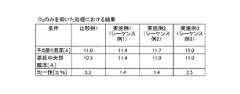
図11は、本発明の実施例7,8を比較例3と共に説明する表図であり、基板処理位置が上部の場合と下部の場合とのそれぞれにおける、HfO2膜の平均膜厚及び膜厚均一性を示している。FIG. 11 is a table for explaining Examples 7 and 8 of the present invention together with Comparative Example 3. The average film thickness and film thickness of the HfO2 film in each of the case where the substrate processing position is the upper part and the case where the substrate processing position is the lower part. It shows uniformity.
(実施例7)
本実施例では、酸化膜形成工程(ステップ3)のシーケンスを、上述のシーケンス例2(図7)と同一とした。すなわち、オゾン供給工程(ステップ3b)においては、第5のバルブ(排気バルブ)243eを閉とした。そして、原料ガス供給工程(ステップ1)〜酸化膜形成工程(ステップ3)を1サイクルとし、このサイクルを複数回繰り返すALD法により、基板上に所定の膜厚のHfO2膜を形成した。(Example 7)
In this embodiment, the sequence of the oxide film forming step (step 3) is the same as the above-described sequence example 2 (FIG. 7). That is, in the ozone supply process (step 3b), the fifth valve (exhaust valve) 243e was closed. Then, the raw material gas supply step (Step 1) to oxide film formation step (step 3) as one cycle, by ALD repeating this cycle a plurality of times to form a predetermined film thickness of the HfO2 film on the substrate.
(実施例8)
本実施例では、酸化膜形成工程(ステップ3)のシーケンスを、上述のシーケンス例3(図8)と同一とした。すなわち、オゾン供給工程(ステップ3b)においては、第5のバルブ(排気バルブ)243eの開度を調整し、処理室201の圧力を平均圧力に調圧した。そして、原料ガス供給工程(ステップ1)〜酸化膜形成工程(ステップ3)を1サイクルとし、このサイクルを複数回繰り返すALD法により、基板上に所定の膜厚のHfO2膜を形成した。(Example 8)
In this embodiment, the sequence of the oxide film forming step (step 3) is the same as the above-described sequence example 3 (FIG. 8). That is, in the ozone supply process (step 3b), the opening degree of the fifth valve (exhaust valve) 243e was adjusted, and the pressure in the
(比較例3)
本比較例では、図5に示すように、オゾンガスをバッファタンク102内に充填することなく、処理室201内に連続的に供給した。図5は、比較例に係る酸化膜形成工程のシーケンス図である。すなわち、バルブAV1とバルブAV2とを同時に開け、オゾン充填工程(ステップ3a)を実施することなく(オゾンガスをパルス的に供給することなく)、ALD法によりのHfO2膜の形成を行った。(Comparative Example 3)
In this comparative example, as shown in FIG. 5, ozone gas was continuously supplied into the
図11によれば、実施例7,8のいずれにおいても、比較例3と比較して、膜厚均一性が向上していることが分かる。なお、実施例7,8の膜厚、比較例3の膜厚がそれぞれ異なっているが、これは、実施例7,8のALDサイクル数が、比較例1のALDサイクル数よりも少ないためであり、実施例7,8の成膜速度が比較例3の成膜速度より遅いわけではない。 As can be seen from FIG. 11, in any of Examples 7 and 8, film thickness uniformity is improved as compared with Comparative Example 3. The film thickness of Examples 7 and 8 and the film thickness of Comparative Example 3 are different from each other because the number of ALD cycles in Examples 7 and 8 is smaller than the number of ALD cycles in Comparative Example 1. In other words, the film formation rates of Examples 7 and 8 are not slower than those of Comparative Example 3.
次に、本発明の実施例9,10を、比較例4と共に説明する。 Next, Examples 9 and 10 of the present invention will be described together with Comparative Example 4.
図12は、基板処理位置が上部、中部、下部のそれぞれにおけるHfO2膜の組成均一性を示す表図であり、(a)は比較例4の組成均一性を、(b)は実施例9の組成均一性を、(c)は実施例10の組成均一性をそれぞれ示している。なお、いずれの場合においても、組成均一性の評価はXPSにて行った。FIG. 12 is a table showing the composition uniformity of the HfO2 film at the substrate processing positions at the upper, middle, and lower portions, where (a) shows the composition uniformity of Comparative Example 4 and (b) shows the Example 9; (C) shows the composition uniformity of Example 10, respectively. In any case, composition uniformity was evaluated by XPS.
(実施例9)
本実施例では、酸化膜形成工程(ステップ3)のシーケンスを、上述のシーケンス例2(図7)と同一とした。すなわち、オゾン供給工程(ステップ3b)においては、第5のバルブ(排気バルブ)243eを閉とした。そして、原料ガス供給工程(ステップ1)〜酸化膜形成工程(ステップ3)を1サイクルとし、このサイクルを複数回繰り返すALD
法により、基板上に所定の膜厚のHfO2膜を形成した。Example 9
In this embodiment, the sequence of the oxide film forming step (step 3) is the same as the above-described sequence example 2 (FIG. 7). That is, in the ozone supply process (step 3b), the fifth valve (exhaust valve) 243e was closed. The source gas supply process (step 1) to the oxide film formation process (step 3) are defined as one cycle, and this cycle is repeated a plurality of times.
A HfO2 film having a predetermined film thickness was formed on the substrate by the method.
(実施例10)
本実施例では、酸化膜形成工程(ステップ3)のシーケンスを、上述のシーケンス例3(図8)と同一とした。すなわち、オゾン供給工程(ステップ3b)においては、第5のバルブ(排気バルブ)243eの開度を調整し、処理室201の圧力を平均圧力に調圧した。そして、原料ガス供給工程(ステップ1)〜酸化膜形成工程(ステップ3)を1サイクルとし、このサイクルを複数回繰り返すALD法により、基板上に所定の膜厚のHfO2膜を形成した。(Example 10)
In this embodiment, the sequence of the oxide film forming step (step 3) is the same as the above-described sequence example 3 (FIG. 8). That is, in the ozone supply process (step 3b), the opening degree of the fifth valve (exhaust valve) 243e was adjusted, and the pressure in the
(比較例4)
本比較例では、オゾンガスをバッファタンク102内に充填することなく、処理室201内に連続的に供給した。すなわち、バルブAV1とバルブAV2とを同時に開け、オゾン充填工程(ステップ3a)を実施することなく(オゾンガスをパルス的に供給することなく)、ALD法によりのHfO2膜の形成を行った。(Comparative Example 4)
In this comparative example, ozone gas was continuously supplied into the
図12によれば、比較例4の場合には、基板処理位置が下部から上部になるにつれて、組成均一性が悪化(±1.40%から±3.00%に悪化)していることが分かる。すなわち、比較例4の場合には、基板処理位置が下部から上部になるにつれてウエハ中央部へのオゾン供給量が低下してしまっていることが分かる。これに対し、実施例9,10のいずれにおいても、基板処理位置が変化しても高い組成均一性が得られる(実施例9の場合には±0.9〜±1.0%、実施例10の場合には±1.25%)ことが分かる。すなわち、実施例9,10のいずれにおいても、基板処理位置が下部から上部になるにつれてウエハ中央部へのオゾン供給量が低下してしまうことを抑制できることが分かる。 According to FIG. 12, in the case of Comparative Example 4, the composition uniformity deteriorates (deteriorates from ± 1.40% to ± 3.00%) as the substrate processing position changes from the lower part to the upper part. I understand. In other words, in the case of Comparative Example 4, it can be seen that the ozone supply amount to the wafer center decreases as the substrate processing position changes from the lower part to the upper part. On the other hand, in any of Examples 9 and 10, high composition uniformity can be obtained even if the substrate processing position is changed (in the case of Example 9, ± 0.9 to ± 1.0%, Examples In the case of 10, ± 1.25%). That is, in any of Examples 9 and 10, it can be understood that the ozone supply amount to the wafer central portion can be suppressed from decreasing from the lower to the upper substrate processing position.
<第4の実施形態>
次に、本発明の第4の実施形態に係る基板処理装置の構成、及び該基板処理装置により実施される基板処理工程について説明する。<Fourth Embodiment>
Next, a configuration of a substrate processing apparatus according to the fourth embodiment of the present invention and a substrate processing process performed by the substrate processing apparatus will be described.
(1)基板処理装置の構成
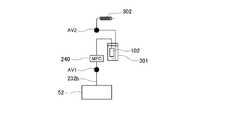
まず、本実施形態に係る基板処理装置の構成を、図13を参照しながら説明する。図13は、本実施形態に係る基板処理装置の処理炉及びガス供給ユニットの概略構成図である。本実施形態においては、ガス供給ユニットが、オゾナイザ52から第2のガス供給ノズル233bに至るオゾンガス供給経路を複数備えており、これら複数のオゾンガス供給経路が並列に設けられている点が、第3の実施形態と異なる。なお、他の構成は、コントローラ280の酸化シーケンスを除き第3の実施形態と同じである。以下、本実施形態に係るガス供給ユニットの構成について説明する。(1) Configuration of Substrate Processing Apparatus First, the configuration of the substrate processing apparatus according to the present embodiment will be described with reference to FIG. FIG. 13 is a schematic configuration diagram of a processing furnace and a gas supply unit of the substrate processing apparatus according to the present embodiment. In the present embodiment, the gas supply unit includes a plurality of ozone gas supply paths from the
図13に示すように、第2のガス供給ノズル233bの上流端には、第2のガス供給管232bの下流端が接続されている。第2のガス供給管232bは、中流付近において複数本(図13ではN本)の支線に並列に分岐している。分岐した各支線は、上流側で再び合流して一本化し、オゾナイザ52に接続されている。第2のガス供給管232bが並列に分岐した各支線には、上流側から順に、オゾン導入バルブAV1−1〜AV1−N、第1のマスフローコントローラ241a−1〜241a−N、処理室201に接続されたガス溜り部としてのバッファタンク102−1〜102−N、オゾン供給バルブAV2−1〜AV2−Nがそれぞれ設けられている。 As shown in FIG. 13, the downstream end of the second
オゾン供給バルブAV2−1〜AV2−Nを閉、オゾン導入バルブAV1−1〜AV1−Nを開とすることで、第1のマスフローコントローラ241a−1〜241a−Nにより流量調整しつつ、バッファタンク102−1〜102−N内にオゾンガスを充填するこ
とが可能なように構成されている。その後、オゾン供給バルブAV2−1〜AV2−Nを順番に開とすることで、バッファタンク102−1〜102−N内に充填されたオゾンガスを、処理室201内にパルス的に供給(フラッシュ供給)することが可能なように構成されている。また、オゾン供給バルブAV2−1〜AV2−Nを空ける時間間隔を制御することで、パルス供給の時間間隔を狭め、酸化処理速度を増大させることが可能なように構成されている。By closing the ozone supply valves AV2-1 to AV2-N and opening the ozone introduction valves AV1-1 to AV1-N, while adjusting the flow rate by the first
(2)基板処理工程
次に、半導体デバイスの製造工程の一つとして実施される本実施形態に係る基板処理工程について、図14を参照しながら説明する。図14は、本実施形態に係るガス供給ユニットの動作及びバルブ開閉シーケンスを例示する図である。本実施形態に係る基板処理工程は、酸化膜形成工程(ステップ3)において、並列に設けられた複数のオゾン供給経路から、酸化ガスとしてのオゾンガスを処理室201内に順番にパルス的に供給(フラッシュ供給)する点が、第3の実施形態と異なる。本実施形態に係る基板処理工程は、図13に示す基板処理装置により実施される。以下の説明において、基板処理装置を構成する各部の動作は、コントローラ280により制御される。(2) Substrate Processing Step Next, a substrate processing step according to this embodiment that is performed as one of the semiconductor device manufacturing steps will be described with reference to FIG. FIG. 14 is a diagram illustrating the operation of the gas supply unit and the valve opening / closing sequence according to this embodiment. In the substrate processing step according to the present embodiment, in the oxide film forming step (step 3), ozone gas as an oxidizing gas is sequentially supplied in a pulsed manner into the
(ウエハ搬入工程〜原料ガス除去工程(ステップ2))
まず、上述の実施形態と同様に、ウエハ搬入工程、原料ガス供給工程(ステップ1)及び原料ガス除去工程(ステップ2)を順次実施する。(Wafer carry-in process to source gas removal process (step 2))
First, similarly to the above-described embodiment, a wafer carry-in process, a source gas supply process (step 1), and a source gas removal process (step 2) are sequentially performed.
(酸化膜形成工程(ステップ3))
次に、酸化膜形成工程(ステップ3)を実施する。なお、図14に例示する酸化膜形成工程(ステップ3)では、3系統数のオゾン供給系統を用い、オゾンガスを処理室201内に順番にパルス的に供給(フラッシュ供給)する。(Oxide film forming step (step 3))
Next, an oxide film forming step (step 3) is performed. Note that in the oxide film formation step (step 3) illustrated in FIG. 14, ozone gas is supplied into the
まず図14の[1]に示すように、オゾン供給バルブAV2−1〜AV2−3、及びオゾン導入バルブAV1−2,AV1−3を閉、オゾン導入バルブAV1−1を開とし、第1のマスフローコントローラ241a−1で流量調整しつつ、バッファタンク102−1内にオゾンガスを充填する(オゾン充填工程(ステップ3a−1))。 First, as shown in [1] in FIG. 14, the ozone supply valves AV2-1 to AV2-3, the ozone introduction valves AV1-2 and AV1-3 are closed, the ozone introduction valve AV1-1 is opened, and the first While adjusting the flow rate with the
所定時間が経過し、バッファタンク102−1内に所定量のオゾンガスが充填され、バッファタンク102−1内の圧力が例えば100000Paに到達したら、図14の[2]に示すように、オゾン導入バルブAV1−1を閉、オゾン供給バルブAV2−1を開とし、バッファタンク102−1内に充填されていたオゾンガスを処理室201内に供給する(オゾン供給工程(ステップ3b−1))。オゾン供給工程(ステップ3b−1)においては、バッファタンク102−1内に充填されたオゾンガスが、処理室201内にパルス的に供給(フラッシュ供給)される。オゾンガスは、ウエハ200の表面に化学吸着しているTEMAHと表面反応し、ウエハ200上にHfO2膜が成膜される。なお、オゾン供給工程(ステップ3b)では、オゾンを供給した直後の処理室201内の圧力が例えば1〜1000Paの範囲内になるようにする。When the predetermined time has elapsed and the buffer tank 102-1 is filled with a predetermined amount of ozone gas and the pressure in the buffer tank 102-1 reaches, for example, 100,000 Pa, as shown in [2] in FIG. The AV 1-1 is closed, the ozone supply valve AV2-1 is opened, and the ozone gas filled in the buffer tank 102-1 is supplied into the processing chamber 201 (ozone supply step (step 3b-1)). In the ozone supply process (step 3b-1), the ozone gas filled in the buffer tank 102-1 is supplied in a pulsed manner (flash supply) into the
また、図14の[2]に示すように、オゾン供給工程(ステップ3b−1)の実施と並行して、オゾン導入バルブAV1−2を開とし、第1のマスフローコントローラ241a−2で流量調整しつつ、バッファタンク102−2内にオゾンガスを充填する(オゾン充填工程(ステップ3a−2))。 Further, as shown in [2] of FIG. 14, in parallel with the execution of the ozone supply step (step 3b-1), the ozone introduction valve AV1-2 is opened and the flow rate is adjusted by the first
所定時間が経過し、バッファタンク102−2内に所定量のオゾンガスが充填され、バッファタンク102−2内の圧力が例えば100000Paに到達したら、図14の[3]に示すように、オゾン導入バルブAV1−2を閉、オゾン供給バルブAV2−2を開と
し、バッファタンク102−2内に充填されていたオゾンガスを処理室201内に供給する(オゾン供給工程(ステップ3b−2))。オゾン供給工程(ステップ3b−2)においては、バッファタンク102−2内に充填されたオゾンガスが、処理室201内にパルス的に供給(フラッシュ供給)される。オゾンガスは、ウエハ200の表面に化学吸着しているTEMAHと表面反応し、ウエハ200上にHfO2膜が成膜される。なお、オゾン供給工程(ステップ3b−1)では、オゾンを供給した直後の処理室201内の圧力が例えば1〜1000Paの範囲内になるようにする。When a predetermined amount of time has elapsed and the buffer tank 102-2 is filled with a predetermined amount of ozone gas and the pressure in the buffer tank 102-2 reaches, for example, 100,000 Pa, as shown in [3] in FIG. AV1-2 is closed, ozone supply valve AV2-2 is opened, and ozone gas filled in buffer tank 102-2 is supplied into processing chamber 201 (ozone supply step (step 3b-2)). In the ozone supply process (step 3b-2), the ozone gas filled in the buffer tank 102-2 is supplied in pulses (flash supply) into the
また、図14の[3]に示すように、オゾン供給工程(ステップ3b−2)の実施と並行して、オゾン導入バルブAV1−3を開とし、第1のマスフローコントローラ241a−3で流量調整しつつ、バッファタンク102−3内にオゾンガスを充填する(オゾン充填工程(ステップ3a−3))。 Further, as shown in [3] of FIG. 14, in parallel with the execution of the ozone supply process (step 3b-2), the ozone introduction valve AV1-3 is opened and the flow rate is adjusted by the first
所定時間が経過し、バッファタンク102−3内に所定量のオゾンガスが充填され、バッファタンク102−3内の圧力が例えば100000Paに到達したら、図14の[4]に示すように、オゾン導入バルブAV1−3を閉、オゾン供給バルブAV2−3を開とし、バッファタンク102−3内に充填されていたオゾンガスを処理室201内に供給する(オゾン供給工程(ステップ3b−3))。オゾン供給工程(ステップ3b−3)においては、バッファタンク102−3内に充填されたオゾンガスが、処理室201内にパルス的に供給(フラッシュ供給)される。オゾンガスは、ウエハ200の表面に化学吸着しているTEMAHと表面反応し、ウエハ200上にHfO2膜が成膜される。なお、オゾン供給工程(ステップ3b−3)では、オゾンを供給した直後の処理室201内の圧力が例えば1〜1000Paの範囲内になるようにする。When a predetermined amount of time has elapsed and the buffer tank 102-3 is filled with a predetermined amount of ozone gas and the pressure in the buffer tank 102-3 reaches, for example, 100000 Pa, as shown in [4] in FIG. AV1-3 is closed, ozone supply valve AV2-3 is opened, and ozone gas filled in the buffer tank 102-3 is supplied into the processing chamber 201 (ozone supply step (step 3b-3)). In the ozone supply process (step 3b-3), the ozone gas filled in the buffer tank 102-3 is supplied in a pulsed manner (flash supply) into the
また、図14の[4]に示すように、オゾン供給工程(ステップ3b−3)の実施と並行して、オゾン導入バルブAV1−1を開とし、第1のマスフローコントローラ241a−3で流量調整しつつ、バッファタンク102−1内にオゾンガスを充填する(オゾン充填工程(ステップ3a−1))。 Further, as shown in [4] of FIG. 14, in parallel with the execution of the ozone supply step (step 3b-3), the ozone introduction valve AV1-1 is opened and the flow rate is adjusted by the first
以後、オゾン充填工程(ステップ3a−1)からオゾン供給工程(ステップ3b−3)を1サイクルとしてこのサイクルを所定回数繰り返した後、オゾン供給バルブAV2−1〜AV2−3を閉とし、酸化膜形成工程(ステップ3)を終了する。なお、酸化膜形成工程(ステップ3)の実施中及び終了後は、排気管231の第5のバルブ243eは常に開いたままとし、真空ポンプ246により処理室201内を排気し、残留オゾンおよびオゾンの中間体を処理室201内から排除するようにする。なお、第5のバルブ243eの開度を調整し、処理室201内の圧力を調圧するようにしてもよい。なお、処理室201内からの残留オゾンおよびオゾンの中間体の除去が完了するまでは、パージガスとしてのN2を処理室201内へ供給するようにすれば、処理室201内から残留オゾンおよびオゾンの中間体を排除する効果が更に高まる。Thereafter, the ozone filling process (step 3a-1) to the ozone supplying process (step 3b-3) are set as one cycle, and this cycle is repeated a predetermined number of times. Then, the ozone supply valves AV2-1 to AV2-3 are closed, and the oxide film The formation process (step 3) is completed. During and after the oxide film formation step (step 3), the
(繰り返し工程)
その後、上述した原料ガス供給工程(ステップ1)〜酸化膜形成工程(ステップ3)を1サイクルとし、このサイクルを複数回繰り返すことにより、ウエハ200上に所定の膜厚のHfO2膜を成膜し、本実施形態に係る基板処理工程を終了する。そして、ウエハ搬入工程と逆の手順により、処理室201内から処理後のウエハ200を搬出する。(Repeated process)
Thereafter, the above-described source gas supply process (step 1) to oxide film formation process (step 3) are set as one cycle, and this cycle is repeated a plurality of times to form a HfO2 film having a predetermined thickness on the
なお、本実施形態においては、並列に設けるオゾンガス供給経路の数(バッファタンク102−1〜102Nの数)は、酸化膜形成に必要な処理時間と製造コストのバランスに基づいて決定するとよい。 In the present embodiment, the number of ozone gas supply paths provided in parallel (the number of buffer tanks 102-1 to 102N) may be determined based on the balance between the processing time required for forming the oxide film and the manufacturing cost.
(3)本実施形態に係る効果
本実施形態によれば、上述の効果に加え、以下に示す1つ又は複数の効果を更に奏する。(3) Effects according to this embodiment According to this embodiment, in addition to the above-described effects, one or more effects described below are further exhibited.
(a)本実施形態によれば、オゾン供給バルブAV2−1〜AV2−Nを空ける時間間隔を制御することで、パルス供給の時間間隔を狭め、酸化処理速度を増大させ、基板処理のスループット(生産性)を向上させることが可能となる。(A) According to the present embodiment, by controlling the time intervals for opening the ozone supply valves AV2-1 to AV2-N, the pulse supply time interval is narrowed, the oxidation treatment rate is increased, and the substrate processing throughput ( (Productivity) can be improved.
(b)また、本実施形態によれば、ベントラインから排出するオゾンの浪費量が少なくなる。そのため、消耗品であるオゾナイザ52の寿命が長くすることができ、ランニングコストを低減させることができる。(B) Moreover, according to this embodiment, the waste amount of ozone discharged | emitted from a vent line decreases. Therefore, the life of the
<本発明の他の実施形態>
以上、本発明の実施の形態を具体的に説明したが、本発明は上述の実施形態に限定されるものではなく、その要旨を逸脱しない範囲で種々変更可能である。<Other Embodiments of the Present Invention>
As mentioned above, although embodiment of this invention was described concretely, this invention is not limited to the above-mentioned embodiment, It can change variously in the range which does not deviate from the summary.
例えば、本発明は、HfOx膜以外の膜(Si酸化膜(SiO)、Hf酸化膜(HfOx)、Zr酸化膜(ZrO)、AI酸化膜、Ti酸化膜、Ta酸化膜、Ru酸化膜、lr酸化膜など)を成膜する場合にも適用可能である。 For example, the present invention provides a film other than the HfOx film (Si oxide film (SiO), Hf oxide film (HfOx), Zr oxide film (ZrO), AI oxide film, Ti oxide film, Ta oxide film, Ru oxide film, lr. The present invention can also be applied when an oxide film or the like is formed.
また、原料ガスとしては、常温で液体である液体原料としてのテトラキスエチルメチルアミノハフニウム(TEHAH)を気化させたTEMAHガスに限らず、テトラキスエチルメチルアミノジルコニウム(TEMAZ)などの他の有機金属液体原料を気化させたガスを使用することができる。また、酸化ガスとしては、オゾン(O3)に限定せず、他の酸素含有ガスを用いることも可能である。The raw material gas is not limited to TEMAH gas obtained by vaporizing tetrakisethylmethylaminohafnium (TEHAH) as a liquid raw material that is liquid at room temperature, but other organometallic liquid raw materials such as tetrakisethylmethylaminozirconium (TEMAZ). The gas which vaporized can be used. The oxidizing gas is not limited to ozone (O3 ), and other oxygen-containing gases can be used.
また、ウエハ200上に形成する薄膜の種類によっては、処理室201内に供給する原料ガスとして、常温で液体である原料を気化器242によって気化させて得られるガスの他、常温で気体であるガスを用いることが出来る。係る場合、液体原料供給源、液体マスフローコントローラ240、気化器242の代わりに、原料ガス供給源やマスフローコントローラ(共に図示しない)を設けることとしても良い。また、処理室201内に供給する酸化ガスの種別や濃度によっては、第2のキャリアガス供給管234bを取り外しても良い。 In addition, depending on the type of thin film formed on the
また、第3、第4の実施形態では、基板処理装置がノーマルフロー方式の縦型基板処理装置として構成された場合を例示しているが、係る形態に限らず、サイドフロー方式の縦型基板処理装置として構成されていてもよい。図17は、第3の実施形態に係るガス供給ユニットをサイドフロー方式の縦型基板処理装置に適応した場合の概略構成図である。 Further, in the third and fourth embodiments, the case where the substrate processing apparatus is configured as a normal flow type vertical substrate processing apparatus is illustrated, but the present invention is not limited thereto, and the side flow type vertical substrate is used. It may be configured as a processing device. FIG. 17 is a schematic configuration diagram when the gas supply unit according to the third embodiment is applied to a side flow type vertical substrate processing apparatus.
<本発明の好ましい態様>
次に、本発明の好ましい態様を付記する。<Preferred embodiment of the present invention>
Next, preferred embodiments of the present invention will be additionally described.
(付記1)
基板を収容した処理室内に原料ガスを供給する原料ガス供給工程と、
前記処理室内に残留する前記原料ガスおよび前記原料ガスの中間体を除去する原料ガス除去工程と、
前記処理室内の雰囲気の排気を実質的に止めた状態で、前記処理室内にオゾンを供給するオゾン供給工程と、
前記処理室内に残留する前記オゾンおよび前記オゾンの中間体を除去するオゾン除去工程と、
を複数回繰り返して前記原料ガスと前記オゾンとを互いに混合しないよう交互に供給し、前記基板の表面に酸化膜を形成する基板処理方法。(Appendix 1)
A source gas supply step for supplying source gas into the processing chamber containing the substrate;
A source gas removal step of removing the source gas remaining in the processing chamber and an intermediate of the source gas; and
An ozone supply step of supplying ozone into the processing chamber in a state where the exhaust of the atmosphere in the processing chamber is substantially stopped;
An ozone removal step of removing the ozone remaining in the processing chamber and an intermediate of the ozone;
Is repeated a plurality of times to alternately supply the source gas and the ozone so as not to mix with each other, thereby forming an oxide film on the surface of the substrate.
好ましくは、
前記原料ガスは常温常圧で液体原料であって、
前記原料ガス供給工程では、前記処理室内の雰囲気を排気しつつ前記原料ガスを前記処理室内に供給する。Preferably,
The source gas is a liquid source at normal temperature and pressure,
In the source gas supply step, the source gas is supplied into the processing chamber while exhausting the atmosphere in the processing chamber.
また好ましくは、
前記オゾン供給工程では、前記オゾンを供給した直後の前記処理室内の圧力が1〜1000Paである。Also preferably,
In the ozone supply step, the pressure in the processing chamber immediately after supplying the ozone is 1-1000 Pa.
また好ましくは、
前記オゾン供給工程では、前記処理室内の圧力を平均圧力で調圧しつつ前記処理室内に前記オゾンを供給する。Also preferably,
In the ozone supply step, the ozone is supplied into the processing chamber while adjusting the pressure in the processing chamber with an average pressure.
また好ましくは、
前記オゾン供給工程の前に、前記処理室に接続されたガス溜り部内に前記オゾンを充填するオゾン充填工程を有し、
前記オゾン供給工程では、前記ガス溜り部内に充填された前記オゾンを前記処理室内に供給する。Also preferably,
Before the ozone supply step, it has an ozone filling step of filling the ozone in a gas reservoir connected to the processing chamber,
In the ozone supply step, the ozone filled in the gas reservoir is supplied into the processing chamber.
また好ましくは、
前記オゾン充填工程を、前記原料ガス供給工程および/または前記原料ガス除去工程と同時に行う。すなわち、前記オゾン充填工程を、前記原料ガス供給工程と同時に行うか、前記原料ガス除去工程と同時に行うか、もしくは、前記原料ガス供給工程および前記原料ガス除去工程と同時に行う。Also preferably,
The ozone filling step is performed simultaneously with the source gas supply step and / or the source gas removal step. That is, the ozone filling step is performed simultaneously with the source gas supply step, the source gas removal step, or the source gas supply step and the source gas removal step.
また好ましくは、前記オゾン充填工程では、前記ガス溜り部内の圧力が100000Paになるまで、前記ガス溜り部内に前記オゾンを充填する。 Preferably, in the ozone filling step, the ozone is filled in the gas reservoir until the pressure in the gas reservoir becomes 100000 Pa.
また好ましくは、
前記各工程は、前記基板を第1の温度に加熱しつつ、前記ガス溜り部と前記処理室とを接続するガス供給管を第2の温度に加熱し、さらに、前記ガス溜り部を第3の温度に冷却しつつ行い、
前記第1の温度は前記第2の温度より高く、前記第2の温度は前記第3の温度より高い。Also preferably,
In each of the steps, while heating the substrate to the first temperature, the gas supply pipe connecting the gas reservoir and the processing chamber is heated to the second temperature, and the gas reservoir is While cooling to the temperature of
The first temperature is higher than the second temperature, and the second temperature is higher than the third temperature.
(付記2)
基板を収容した処理室内に原料ガスを供給する工程と、
前記処理室内の雰囲気を排気する工程と、
前記処理室に接続されたガス溜り部内にオゾンを充填する工程と、
前記処理室内に、前記ガス溜り部内に充填された前記オゾンを供給する工程と、
前記処理室内の雰囲気を排気する工程と、
を複数回行って前記原料ガスと前記オゾンとを互いに混合しないように交互に供給し、前記基板の表面に酸化膜を形成する基板処理方法。(Appendix 2)
Supplying a source gas into a processing chamber containing a substrate;
Exhausting the atmosphere in the processing chamber;
Filling ozone in a gas reservoir connected to the processing chamber;
Supplying the ozone filled in the gas reservoir into the processing chamber;
Exhausting the atmosphere in the processing chamber;
Is performed a plurality of times to supply the source gas and the ozone alternately so as not to mix with each other, thereby forming an oxide film on the surface of the substrate.
(付記3)
基板を処理室内に搬入する基板搬入工程と、
前記処理室内の雰囲気の排気を実質的に止めた状態で、前記処理室内にオゾンを供給す
るオゾン供給工程と、
前記処理室内に残留する前記オゾンおよび前記オゾンの中間体を除去するオゾン除去工程と、を有し、
前記オゾン供給工程と前記オゾン除去工程とを複数回繰り返し、前記基板の表面に酸化膜を形成する基板処理方法。(Appendix 3)
A substrate carrying-in process for carrying the substrate into the processing chamber;
An ozone supply step of supplying ozone into the processing chamber in a state where the exhaust of the atmosphere in the processing chamber is substantially stopped;
An ozone removal step of removing the ozone remaining in the processing chamber and the intermediate of the ozone,
A substrate processing method for forming an oxide film on a surface of the substrate by repeating the ozone supply step and the ozone removal step a plurality of times.
好ましくは、
前記オゾン供給工程では、前記オゾンを供給した直後の前記処理室内の圧力が0.1〜1000Paである。Preferably,
In the ozone supply step, the pressure in the processing chamber immediately after supplying the ozone is 0.1 to 1000 Pa.
また好ましくは、
前記オゾン供給工程では、前記処理室内の圧力を平均圧力で調圧しつつ前記処理室内に前記オゾンを供給する。Also preferably,
In the ozone supply step, the ozone is supplied into the processing chamber while adjusting the pressure in the processing chamber with an average pressure.
また好ましくは、
前記オゾン供給工程の前に、前記処理室に接続されたガス溜り部内に前記オゾンを充填するオゾン充填工程を有し、
前記オゾン供給工程では、前記ガス溜り部内に充填された前記オゾンを前記処理室内に供給する。Also preferably,
Before the ozone supply step, it has an ozone filling step of filling the ozone in a gas reservoir connected to the processing chamber,
In the ozone supply step, the ozone filled in the gas reservoir is supplied into the processing chamber.
また好ましくは、
前記オゾン充填工程では、前記ガス溜り部内の圧力が100000Paになるまで、前記ガス溜り部内に前記オゾンを充填する。Also preferably,
In the ozone filling step, the ozone is filled in the gas reservoir until the pressure in the gas reservoir becomes 100000 Pa.
また好ましくは、
前記各工程は、前記基板を第1の温度に加熱しつつ、前記ガス溜り部と前記処理室とを接続するガス供給管を第2の温度に加熱し、さらに、前記ガス溜り部を第3の温度に冷却しつつ行い、
前記第1の温度は前記第2の温度より高く、前記第2の温度は前記第3の温度より高い。Also preferably,
In each of the steps, while heating the substrate to the first temperature, the gas supply pipe connecting the gas reservoir and the processing chamber is heated to the second temperature, and the gas reservoir is While cooling to the temperature of
The first temperature is higher than the second temperature, and the second temperature is higher than the third temperature.
(付記4)
基板を収容した処理室に接続されたガス溜り部内にオゾンを充填する工程と、
前記ガス溜り部内に充填された前記オゾンを前記処理室内に供給する工程と、
前記処理室内の雰囲気を排気する工程と、
を複数繰り返して、前記基板の表面に酸化膜を形成する基板処理方法。(Appendix 4)
Filling a gas reservoir connected to a processing chamber containing a substrate with ozone;
Supplying the ozone filled in the gas reservoir into the processing chamber;
Exhausting the atmosphere in the processing chamber;
The substrate processing method of forming an oxide film on the surface of the substrate by repeating a plurality of steps.
(付記5)
基板を処理する処理室と、
前記処理室内にオゾンを供給するガス供給ユニットと、
前記処理室内の雰囲気を排気する排気ユニットと、
制御部と、を有し、
前記ガス供給ユニットは、前記処理室と接続されたオゾン供給路と、前記オゾン供給路の開閉を行うオゾン供給バルブと、を備え、
前記排気ユニットは、前記処理室と接続された排気路と、前記排気路を開閉する排気バルブと、を備え、
前記制御部は、
前記オゾンを前記処理室内に供給するときは、前記処理室内の雰囲気の排気を実質的に止めた状態で前記オゾン供給路から前記オゾンを前記処理室内に供給するように前記ガス供給ユニットおよび前記排気ユニットを制御する基板処理装置。(Appendix 5)
A processing chamber for processing the substrate;
A gas supply unit for supplying ozone into the processing chamber;
An exhaust unit for exhausting the atmosphere in the processing chamber;
A control unit,
The gas supply unit includes an ozone supply path connected to the processing chamber, and an ozone supply valve that opens and closes the ozone supply path.
The exhaust unit includes an exhaust path connected to the processing chamber, and an exhaust valve that opens and closes the exhaust path,
The controller is
When supplying the ozone into the processing chamber, the gas supply unit and the exhaust gas are supplied so as to supply the ozone from the ozone supply path into the processing chamber in a state where the exhaust of the atmosphere in the processing chamber is substantially stopped. A substrate processing apparatus for controlling the unit.
好ましくは、
前記ガス供給ユニットは、前記オゾン供給バルブより上流側に配置され、オゾンを溜めるガス溜り部を有し、
前記制御部は、前記オゾン供給バルブを閉じた状態で、前記オゾンを前記オゾン供給路に供給して前記オゾンを前記ガス溜り部内に溜めた後、前記オゾン供給バルブを開けて前記ガス溜り部内に溜めた前記オゾンを前記処理室内に供給するよう前記ガス供給ユニットを制御する。Preferably,
The gas supply unit is disposed upstream of the ozone supply valve and has a gas reservoir for storing ozone,
The controller supplies the ozone to the ozone supply path with the ozone supply valve closed, stores the ozone in the gas reservoir, and then opens the ozone supply valve to enter the gas reservoir. The gas supply unit is controlled to supply the accumulated ozone into the processing chamber.
また好ましくは、
前記処理室の容積に対する前記ガス溜り部の容積の比率は、1/2100〜1/105である。Also preferably,
The ratio of the volume of the gas reservoir to the volume of the processing chamber is 1/2100 to 1/105.
また好ましくは、
前記ガス供給ユニットは、前記ガス溜り部を冷却する冷却媒体を有する冷却ユニットを備える。Also preferably,
The gas supply unit includes a cooling unit having a cooling medium for cooling the gas reservoir.
また好ましくは、
前記ガス溜り部の内壁は、Fe酸化膜、Ti酸化膜、Al酸化膜、Ni酸化膜、Cr酸化膜のいずれかでコーティングされる。
Also preferably,
The inner wall of the gas reservoir is coated with any one of an Fe oxide film, a Ti oxide film, an Al oxide film, a Ni oxide film, and a Cr oxide film.
(付記6)
基板を収容する処理室と、処理室の外に配置され、処理室内の雰囲気及び基板を加熱する加熱ユニットと、処理室に所望のガスを供給するガス供給ユニットと、処理室内の雰囲気を排気する排気ユニットと、少なくともガス供給ユニットにおけるガス供給動作あるいは排気ユニットにおけるガス排気動作を制御する制御部と、を有する基板処理装置であって、ガス供給ユニットは、処理室内にオゾンを供給するオゾン供給部を有し、オゾン供給部は、オゾン供給路と、処理室との接続部より上流側であるオゾン供給路に配置され、オゾンを溜めるガス溜りと、このガス溜りと処理室との接続部との間であるオゾン供給路に配置されオゾン供給路を開閉するオゾン供給バルブとを有し、制御部は、オゾンを処理室に供給する際には、第一に、オゾン供給バルブを閉じ、オゾンをオゾン供給路に流して所望の量の前記オゾンをガス溜りに溜め、次に、オゾン供給バルブを開けてガス溜りに溜めたオゾンを処理室に供給するようにガス供給ユニットを制御することにより基板上に所望の酸化膜を形成する基板処理装置を提供する。処理室が大気圧よりも減圧されており、オゾン供給溜り圧力が処理室よりも高圧となっており、基板は、基板保持具により、処理室に水平且つ多段配置されている。この状態で、オゾン供給バルブを開とすると、オゾンが各基板の上面に沿ってパルス的に供給されるので、基板がオゾンにより面内膜厚に処理される。(Appendix 6)
A processing chamber that accommodates a substrate, a heating unit that is disposed outside the processing chamber and heats the atmosphere and the substrate in the processing chamber, a gas supply unit that supplies a desired gas to the processing chamber, and an atmosphere in the processing chamber is exhausted A substrate processing apparatus comprising: an exhaust unit; and a control unit that controls at least a gas supply operation in the gas supply unit or a gas exhaust operation in the exhaust unit, wherein the gas supply unit supplies ozone into the processing chamber The ozone supply section is disposed in the ozone supply path upstream of the connection section between the ozone supply path and the processing chamber, and stores a gas reservoir for storing ozone, and a connection section between the gas reservoir and the processing chamber. And an ozone supply valve that opens and closes the ozone supply path, and the controller first supplies ozone to the processing chamber. The ozone supply valve is closed and ozone is allowed to flow through the ozone supply path so that the desired amount of ozone is stored in the gas reservoir. Next, the ozone supply valve is opened to supply the ozone stored in the gas reservoir to the processing chamber Provided is a substrate processing apparatus for forming a desired oxide film on a substrate by controlling a supply unit. The processing chamber is depressurized from the atmospheric pressure, the ozone supply pool pressure is higher than that of the processing chamber, and the substrate is horizontally and multi-stagely arranged in the processing chamber by the substrate holder. When the ozone supply valve is opened in this state, ozone is supplied in pulses along the upper surface of each substrate, so that the substrate is processed to an in-plane film thickness by ozone.
好ましくは、前記制御部は、前記オゾンを前記処理室に供給する際には、前記オゾン供給バルブを閉じ、前記オゾンを前記オゾン供給路に流して所望の量の前記オゾンを前記ガス溜りに溜める第1のステップと、前記オゾン供給バルブを開けて前記ガス溜りに溜めた前記オゾンを前記処理室に供給する第2のステップを所定回数繰り返すように前記ガス供給ユニットを制御することにより前記基板上に所望の酸化膜を形成する基板処理装置。これにより、連続的且つパルス的にオゾンが基板に供給される。この結果、基板が面内均一に処理される。 Preferably, when the ozone is supplied to the processing chamber, the control unit closes the ozone supply valve and causes the ozone to flow into the ozone supply path to accumulate a desired amount of the ozone in the gas reservoir. By controlling the gas supply unit to repeat a first step and a second step of opening the ozone supply valve and supplying the ozone stored in the gas reservoir to the processing chamber a predetermined number of times. A substrate processing apparatus for forming a desired oxide film on the substrate. Thereby, ozone is supplied to the substrate continuously and in pulses. As a result, the substrate is processed uniformly in the surface.
また好ましくは、前記排気ユニットは、排気路と、該排気路を介して接続される真空排気部と、前記排気路を開閉する排気バルブと、を有し、前記制御部は、前記処理室の排気
を止めた状態であるいは前記処理室の排気を非常に絞った状態で、前記ガス溜りから該ガス溜りに溜めた前記オゾンを前記処理室に供給するように前記ガス供給ユニット及び前記排気ユニットを制御することにより前記基板上に所望の酸化膜を形成する基板処理装置。オゾンにより基板を酸化する際に、排気を停止又は排気を絞ると、基板が面内均一に処理される。Preferably, the exhaust unit includes an exhaust path, a vacuum exhaust unit connected via the exhaust path, and an exhaust valve that opens and closes the exhaust path, and the control unit includes The gas supply unit and the exhaust unit are supplied so that the ozone stored in the gas reservoir is supplied from the gas reservoir to the processing chamber in a state where the exhaust is stopped or the exhaust of the processing chamber is very narrowed. A substrate processing apparatus for forming a desired oxide film on the substrate by controlling. When the substrate is oxidized by ozone, if the exhaust is stopped or the exhaust is stopped, the substrate is processed uniformly in the surface.
また好ましくは、前記オゾンを供給した直後の前記処理室内の圧力を0.1〜1000Paとする基板処理装置。0.1Pa未満の場合は、酸化膜の面内均一性が低下し、1000Paを超えると、酸化膜の膜厚が面内均一になる。従って、酸化膜や成膜の際は、オゾンを供給した直後の前記処理室内の圧力を100〜1000Paとするとよい。 Preferably, the substrate processing apparatus has a pressure in the processing chamber of 0.1 to 1000 Pa immediately after the ozone is supplied. When the pressure is less than 0.1 Pa, the in-plane uniformity of the oxide film decreases. When the pressure exceeds 1000 Pa, the thickness of the oxide film becomes in-plane uniform. Therefore, when forming an oxide film or a film, the pressure in the processing chamber immediately after supplying ozone is preferably 100 to 1000 Pa.
また好ましくは、前記ガス溜り内の圧力が100000Paになるまで、前記オゾンを前記ガス溜りに溜める基板処理装置。このような圧力にガス溜りの圧力を定めると、オゾン供給バルブが開放されたときに、基板に向けてパルス的に供給されるオゾンにより、基板の面内均一な酸化、成膜が可能になる。 Also preferably, the substrate processing apparatus stores the ozone in the gas reservoir until the pressure in the gas reservoir becomes 100,000 Pa. When the pressure of the gas reservoir is set to such a pressure, when the ozone supply valve is opened, it is possible to uniformly oxidize and form a film in the surface of the substrate by ozone supplied in a pulsed manner toward the substrate. .
また好ましくは、前記処理室の容積に対する前記ガス溜りの容積比は1/2100〜1/105である請求項1記載の基板処理装置。このように、容積比を決定するとこで、ウエハを面内均一に酸化させ、又面内均一な成膜が可能になる。 2. The substrate processing apparatus according to
また好ましくは、前記制御部は、前記オゾンを前記処理室に供給する際は、平均圧力で調圧するように前記ガス供給ユニット及び前記排気ユニットを制御して所望の酸化膜を形成する基板処理装置。ここで、平均圧力とはオゾンを供給する際に、排気バルブを閉めずにオゾンを供給した場合の圧力から求められる圧力である。平均圧力とすると、所望の酸化膜の厚み面内均一にすることができる。 Preferably, when the ozone is supplied to the processing chamber, the control unit controls the gas supply unit and the exhaust unit so as to adjust the average pressure to form a desired oxide film. . Here, the average pressure is a pressure obtained from the pressure when ozone is supplied without closing the exhaust valve when supplying ozone. If the average pressure is used, the thickness of the desired oxide film can be made uniform in the plane.
また好ましくは、前記排気ユニットは前記処理室の下部に接続される基板処理装置。
排気ユニットが下部に設けられると、処理室内を流れた後に排気することができるので、原料ガス(処理ガス)の無駄がなくなる。また、処理室内でのガスの流れを乱すことなく、酸化や成膜に適した流れを形成するのに適している。In a preferred embodiment, the exhaust unit is connected to a lower portion of the processing chamber.
When the exhaust unit is provided in the lower part, exhaust gas can be exhausted after flowing through the processing chamber, so that the source gas (processing gas) is not wasted. In addition, it is suitable for forming a flow suitable for oxidation or film formation without disturbing the gas flow in the processing chamber.
また好ましくは、前記処理室は、アウタチューブと、前記アウタチューブの内部に設置され、前記複数の基板が積層されて収容される少なくとも下端側が開放したインナチューブとを備え、前記ガス供給ユニットは、前記複数の基板の積層方向に延在するように前記インナチューブの内部に立設され複数のガス噴出口を有するガス供給ノズルを有し、さらに前記処理室は、前記ガス供給ノズルに対向した位置であって、前記インナチューブに設けられた複数の排気口を有する基板処理装置。
このような処理室とすると、各基板に対して水平フローを形成することができるので、各基板の面内均一性を向上させることができる。また、インナチューブとアウタチューブとの間の間隙を通った後の処理ガスと、インナチューブの開放端からの処理ガスとの両方を排気させることができるので、ガスの置換効率を向上させることができる。Further preferably, the processing chamber includes an outer tube, and an inner tube that is installed inside the outer tube and has the plurality of substrates stacked and accommodated and opened at least at a lower end side, and the gas supply unit includes: A gas supply nozzle provided in the inner tube so as to extend in the stacking direction of the plurality of substrates and having a plurality of gas ejection ports; and the processing chamber is positioned opposite the gas supply nozzle. A substrate processing apparatus having a plurality of exhaust ports provided in the inner tube.
With such a processing chamber, since a horizontal flow can be formed for each substrate, the in-plane uniformity of each substrate can be improved. In addition, since the processing gas after passing through the gap between the inner tube and the outer tube and the processing gas from the open end of the inner tube can be exhausted, the gas replacement efficiency can be improved. it can.
また好ましくは、前記オゾン供給部は、前記ガス溜りを冷却する冷却媒体を有する冷却ユニットを備える基板処理装置。
ガス溜りを冷却すると、オゾンの寿命が延びるので、一定の品質で基板を処理することが可能になる。Preferably, the ozone supply unit includes a cooling unit having a cooling medium for cooling the gas reservoir.
When the gas reservoir is cooled, the lifetime of ozone is extended, so that the substrate can be processed with a certain quality.
また好ましくは、前記冷却媒体は、冷却水、ペルチェ素子のいずれかである基板処理装置。
簡単な構成で確実にオゾン供給溜りを冷却できるので、信頼性が向上する。In a preferred embodiment, the cooling medium is a cooling water or a Peltier element.
Since the ozone supply reservoir can be reliably cooled with a simple configuration, the reliability is improved.
また好ましくは、前記ガス溜りの内壁は、Fe酸化膜、Ti酸化膜、AI酸化膜、Ni酸化膜、Cr酸化膜のいずれかでコーティングされる基板処理装置。これにより、オゾンと冷却溜りの反応が防止されるので、基板処理の信頼性を向上させることができる。 Preferably, the inner wall of the gas reservoir is coated with any one of an Fe oxide film, a Ti oxide film, an AI oxide film, a Ni oxide film, and a Cr oxide film. Thereby, since the reaction between ozone and the cooling pool is prevented, the reliability of the substrate processing can be improved.
また好ましくは、前記ガス供給ユニットは、前記処理室にオゾンとは異なる原料ガスを供給する原料ガス供給部を有し、前記原料ガス供給部は、原料ガス供給路と、前記原料ガス供給路に配置され前記原料ガス供給路を開閉する原料ガス供給バルブとを有し、前記制御部は、前記原料ガスと前記オゾンとを互いに混合しないように所定回数交互に繰り返して前記処理室に供給し、前記原料ガスを前記処理室に供給する際には、前記原料ガス供給路から前記原料ガスを前記処理室に供給すると共に、前記オゾン供給バルブを閉じた状態で前記オゾンを前記オゾン供給路に流して所望の量の前記オゾンを前記ガス溜りに溜めるように前記ガス供給ユニット及び前記排気ユニットを制御することにより前記基板上に所望の酸化膜を形成する基板処理装置。
このような構成とすると、原料ガスにより基板を処理している間にオゾンがガス溜りに蓄えられることができる。オゾンは、原料ガスによる処理が終了した直後に、オゾン供給バルブを開とすることによって、基板に供給され、原料ガスの原料と反応して酸化、又は成膜を行う。Preferably, the gas supply unit includes a source gas supply unit that supplies a source gas different from ozone to the processing chamber, and the source gas supply unit is connected to the source gas supply path and the source gas supply path. A source gas supply valve that is disposed and opens and closes the source gas supply path, and the control unit alternately supplies the source gas and the ozone to the processing chamber a predetermined number of times so as not to mix with each other, When supplying the source gas to the processing chamber, the source gas is supplied to the processing chamber from the source gas supply path, and the ozone is allowed to flow to the ozone supply path with the ozone supply valve closed. And a substrate process for forming a desired oxide film on the substrate by controlling the gas supply unit and the exhaust unit so that a desired amount of ozone is stored in the gas reservoir. Location.
With such a configuration, ozone can be stored in the gas reservoir while the substrate is being processed with the source gas. Ozone is supplied to the substrate by opening the ozone supply valve immediately after the processing with the raw material gas is completed, and reacts with the raw material of the raw material gas to oxidize or form a film.
また好ましくは、前記酸化膜は、Si酸化膜、Hf酸化膜、Zr酸化膜、A1酸化膜、Ti酸化膜、Ta酸化膜、Ru酸化膜、lr酸化膜のいずれかである基板処理装置。 Preferably, the oxide film is any one of a Si oxide film, a Hf oxide film, a Zr oxide film, an A1 oxide film, a Ti oxide film, a Ta oxide film, a Ru oxide film, and an lr oxide film.
また好ましくは、前記原料ガスは、Si原子、Hf原子、Zr原子、A1原子、Ti原子、Ta原子、Ru原子、lr原子を含む有機化合物や上記原子の塩化物のいずれかである基板処理装置。 Preferably, the source gas is any one of an organic compound containing Si atom, Hf atom, Zr atom, A1 atom, Ti atom, Ta atom, Ru atom, or lr atom, or a chloride of the above atom. .
また好ましくは、前記制御部には、さらに、前記原料ガスの前記処理室への供給を止めた後、及び、前記オゾンの前記処理室への供給を止めた後、残留した前記原料ガス又は前記オゾンを除去するように前記ガス供給ユニット及び前記排気ユニットを制御する基板処理装置。
これにより、処理室が清浄化される。Further preferably, after the supply of the source gas to the processing chamber is stopped and the supply of the ozone to the processing chamber is stopped, the control unit further includes the remaining source gas or the A substrate processing apparatus for controlling the gas supply unit and the exhaust unit so as to remove ozone.
Thereby, the processing chamber is cleaned.
(付記7)
処理室に接続されたガス溜りにオゾンを充填する第1の工程と、前記ガス溜りに充填されたオゾンを前記処理室に供給する第2の工程と、前記処理室内の雰囲気を排気する第3の工程と、を含み、前記第1の工程から前記第3の工程を少なくとも1回以上繰り返して行い、前記処理室内に積層して収容された複数の基板の表面に所望の厚さの酸化膜を形成する半導体装置の製造方法。
このような工程により、基板を面内均一に処理して酸化膜を形成することができる。(Appendix 7)
A first step of filling a gas reservoir connected to the processing chamber with ozone, a second step of supplying ozone filled in the gas reservoir to the processing chamber, and a third step of exhausting the atmosphere in the processing chamber. The oxide film having a desired thickness is formed on the surfaces of a plurality of substrates stacked and accommodated in the processing chamber by repeating the first to third steps at least once. For manufacturing a semiconductor device.
Through such a process, the substrate can be uniformly processed in the surface to form an oxide film.
好ましくは、前記第1の工程から前記第3の工程を繰り返すとき、少なくとも1回以上、前記第1の工程と前記第3の工程を同時に行う場合を有する半導体装置の製造方法。オゾンをパルス的に供給しながら排気すると、面内均一に酸化膜を形成することができる。 Preferably, when the third step is repeated from the first step, the method for manufacturing a semiconductor device includes a case where the first step and the third step are simultaneously performed at least once. When ozone is exhausted while being supplied in pulses, an oxide film can be formed uniformly in the surface.
(付記8)
原料ガスとオゾンを互いに混合しないように所定回数交互に繰り返して処理室に供給して、前記処理室内に積層して収容された複数の基板の表面に所望の厚さの酸化膜を形成する半導体装置の製造方法であって、前記処理室に前記原料ガスを供給する第1の工程と、前記処理室に接続されたガス溜りに前記オゾンを充填する第2の工程と、前記ガス溜りに充填されたオゾンを前記処理室に供給する第3の工程と、前記処理室内の雰囲気を排気す
る第4の工程と、を含み、前記第1の工程から前記第4の工程を少なくとも1回以上繰り返して行い、前記処理室内に積層して収容された複数の基板の表面に所望の厚さの酸化膜を形成する半導体装置の製造方法。このような工程を実施すると、基板に対し面内均一に所望の膜を形成することができる。(Appendix 8)
A semiconductor in which source gas and ozone are alternately and repeatedly supplied to a processing chamber a predetermined number of times so as not to mix with each other, and an oxide film having a desired thickness is formed on the surfaces of a plurality of substrates stacked and accommodated in the processing chamber A method for manufacturing an apparatus, comprising: a first step of supplying the source gas to the processing chamber; a second step of filling the gas reservoir connected to the processing chamber with the ozone; and filling the gas reservoir. A third step of supplying the treated ozone to the processing chamber, and a fourth step of exhausting the atmosphere in the processing chamber, wherein the first to fourth steps are repeated at least once. And a method of manufacturing a semiconductor device in which an oxide film having a desired thickness is formed on the surfaces of a plurality of substrates housed in a stack in the processing chamber. When such a process is performed, a desired film can be formed uniformly on the substrate.
好ましくは、前記第1の工程から前記第4の工程を繰り返すとき、少なくとも1回以上、前記第1の工程と前記第2の工程を同時に行う場合を有する半導体装置の製造方法。このような構成とすると、原料ガスにより基板を処理している間にオゾンがガス溜りに蓄えられることができる。オゾンは、原料ガスによる処理が終了した直後に、オゾン供給バルブを開とすることによって、基板に供給され、原料ガスの原料と反応して酸化、又は成膜を行う。 Preferably, when the fourth step is repeated from the first step, the method for manufacturing a semiconductor device may include performing the first step and the second step at least once at least once. With such a configuration, ozone can be stored in the gas reservoir while the substrate is being processed with the source gas. Ozone is supplied to the substrate by opening the ozone supply valve immediately after the processing with the raw material gas is completed, and reacts with the raw material of the raw material gas to oxidize or form a film.
104 バッファタンク(ガス溜り)
200 ウエハ(基板)
201 処理室
203 反応管
207 ヒータ(ヒータユニット)
231 排気管(排気路)
232a 第1のガス供給管
232b 第2のガス供給管(オゾン供給路)
233a 第1のガス供給ノズル
233b 第2のガス供給ノズル
243e 第5のバルブ(排気バルブ)
246 真空ポンプ(排気ユニット)
248a 第1のガス噴出口
248b 第2のガス噴出口
280 コントローラ(制御部)
AV1 ガス導入バルブ
AV2 ガス供給バルブ104 Buffer tank (Gas reservoir)
200 wafer (substrate)
201
231 Exhaust pipe (exhaust passage)
232a First
233a First
246 Vacuum pump (exhaust unit)
248a
AV1 gas introduction valve AV2 gas supply valve
Claims (14)
Translated fromJapanese前記処理室内の雰囲気を排気する第1の排気工程と、
前記処理室に接続され、前記処理室に対する容積比が1/2100〜1/105であるガス溜り部内にオゾンを供給して充填するオゾン充填工程と、
前記ガス溜り部内に所定量のオゾンが充填された後、前記ガス溜り部内にオゾンを引き続き供給しつつ、前記処理室内の雰囲気の排気を行った状態で、前記処理室内に、前記ガス溜り部内に充填された前記オゾンをフラッシュ供給するオゾン供給工程と、
前記処理室内の雰囲気を排気する第2の排気工程と、
を複数回行って前記原料ガスと前記オゾンとを互いに混合しないように交互に供給し、前記基板の表面に酸化膜を形成する半導体装置の製造方法。A source gas supply step for supplying source gas into the processing chamber containing the substrate;
A first exhaust process for exhausting the atmosphere in the processing chamber;
An ozone filling step connected to theprocessing chamber and supplying ozone intoa gas reservoirhaving a volume ratio of 1/2100 to 1/105 to the processing chamber ;
After the gas reservoir is filled with a predetermined amount of ozone, the atmosphere in the process chamber is exhausted while ozone is continuously supplied into the gas reservoir, and the gas reservoir is in the process chamber. An ozone supplying step for supplying the ozone filled with flash;
A second exhaust process for exhausting the atmosphere in the processing chamber;
Is performed a plurality of times, and the source gas and the ozone are alternately supplied so as not to mix with each other, and an oxide film is formed on the surface of the substrate.
前記ガス溜り部内に所定量のオゾンが充填された後、前記ガス溜り部内にオゾンを引き続き供給しつつ、前記処理室内の雰囲気の排気を行った状態で、前記ガス溜り部内に充填された前記オゾンを前記処理室内にフラッシュ供給するオゾン供給工程と、
前記処理室内の雰囲気を排気する排気工程と、
を複数回行って、前記基板の表面に酸化膜を形成する半導体装置の製造方法。An ozone filling step connected to a processing chamber containing a substrate and supplying ozone intoa gas reservoirhaving a volume ratio of 1/2100 to 1/105 with respect to the processing chamber ;
After the gas reservoir is filled with a predetermined amount of ozone, the ozone filled in the gas reservoir in a state where the atmosphere in the processing chamber is exhausted while ozone is continuously supplied into the gas reservoir. Supplying ozone into the processing chamber;
An exhaust process for exhausting the atmosphere in the processing chamber;
A method of manufacturing a semiconductor device in which an oxide film is formed on the surface of the substrate by performing a plurality of times.
前記処理室内にオゾンを供給するオゾン供給路に、前記処理室側から順に設けられた第2のバルブ、前記処理室に対する容積比が1/2100〜1/105であるガス溜り部、第3のバルブのうち、前記第2のバルブを閉じた状態で前記第3のバルブを開き、前記ガス溜り部内にオゾンを充填するオゾン充填工程と、
前記ガス溜り部内に所定量のオゾンが充填された後、前記処理室内の雰囲気を排気する排気路に設けられた第4のバルブおよび前記第3のバルブを開けた状態で、前記第2のバルブを開けて、前記処理室内に前記ガス溜り部内に充填された前記オゾンを前記処理室内にフラッシュ供給するオゾン供給工程と、
前記処理室内の雰囲気を排気する排気工程と、
を有する半導体装置の製造方法。A source gas supply step of opening a first valve provided in a source gas supply path for supplying source gas into a processing chamber containing a substrate and supplying source gas into the processing chamber;
A second valve provided in order from the processing chamber side to the ozone supply path for supplying ozone into theprocessing chamber; a gas reservoirhaving a volume ratio of 1/2100 to 1/105 to the processing chamber ; of thevalve, opening the third valve is closed the second valve, and the ozone filling step of filling the ozone in the gas reservoir unit,
After the gas reservoir has been filled with a predetermined amount of ozone, the second valve provided in the exhaust passage for exhausting the atmosphere in the processing chamber and the third valve are opened. An ozone supply step for supplying the ozone filled in the gas reservoir into the processing chamber to the processing chamber by flashing;
An exhaust process for exhausting the atmosphere in the processing chamber;
A method for manufacturing a semiconductor device comprising:
前記処理室内にオゾンを供給するガス供給ユニットと、
前記処理室内の雰囲気を排気する排気ユニットと、
制御部と、を有し、
前記ガス供給ユニットは、前記処理室と接続され、前記オゾンを前記処理室内に供給するオゾン供給路を有し、前記オゾン供給路は、前記処理室側から順に、第1のバルブと、
前記処理室に対する容積比が1/2100〜1/105であるガス溜り部と、第2のバルブと、を備え、
前記排気ユニットは、前記処理室と接続され、前記処理室内の雰囲気を排気する排気路と、前記排気路を開閉する排気バルブと、を備え、
前記制御部は、
前記オゾンを前記処理室内に供給するときは、前記第1のバルブを閉じた状態で前記第2のバルブを開け、前記オゾンを前記オゾン供給路に流して前記ガス溜り部内に充填し、前記ガス溜り部内に所定量のオゾンが充填された後、前記排気バルブおよび前記第2バルブを開けた状態で、前記第1のバルブを開けて、前記ガス溜り部内に充填された前記オゾンを前記処理室内にフラッシュ供給するように前記ガス供給ユニットおよび前記排気ユニットを制御する基板処理装置。A processing chamber for processing the substrate;
A gas supply unit for supplying ozone into the processing chamber;
An exhaust unit for exhausting the atmosphere in the processing chamber;
A control unit,
The gas supply unit is connected to the processing chamber and has an ozone supply path for supplying the ozone into the processing chamber. The ozone supply path includes, in order from the processing chamber side, a first valve;
A gas reservoirhaving a volume ratio of 1/2100 to 1/105 to the processing chamber, and a second valve,
The exhaust unit includes an exhaust passage that is connected to the processing chamber and exhausts the atmosphere in the processing chamber, and an exhaust valve that opens and closes the exhaust passage.
The controller is
When supplying the ozone into the processing chamber, the second valve is opened with the first valve closed, and the ozone is supplied to the gas reservoir by flowing the ozone through the ozone supply path. After the reservoir is filled with a predetermined amount of ozone, the first valve is opened with the exhaust valve and the second valve opened, and the ozone filled in the gas reservoir is removed from the processing chamber. A substrate processing apparatus for controlling the gas supply unit and the exhaust unit so as to supply a flash.
前記処理室内に原料ガスおよびオゾンを供給するガス供給ユニットと、
前記処理室内の雰囲気を排気する排気ユニットと、
制御部と、を有し、
前記ガス供給ユニットは、前記処理室と接続され前記原料ガスを前記処理室内に供給する原料ガス供給路と、前記処理室と接続され前記オゾンを前記処理室内に供給するオゾン供給路と、を有し、前記原料ガス供給路は、前記原料ガス供給路を開閉する原料ガスバルブを備え、前記オゾン供給路は、前記処理室側から順に、第1のバルブと、前記処理室に対する容積比が1/2100〜1/105であるガス溜り部と、第2のバルブと、を備え、
前記排気ユニットは、前記処理室と接続された排気路と、前記排気路を開閉する排気バルブと、を備え、
前記制御部は、
前記原料ガスと前記オゾンを交互に前記処理室内に供給し、
前記原料ガスを前記処理室内に供給するときは、前記原料ガスバルブを開けて前記原料ガスを前記処理室内に供給し、
前記オゾンを前記処理室内に供給するときは、前記第1のバルブを閉じた状態で前記第2のバルブを開け、前記オゾンを前記オゾン供給路に流して前記ガス溜り部内に充填し、前記ガス溜り部内に所定量のオゾンが充填された後、前記排気バルブおよび前記第2バルブを開けた状態で、前記第1のバルブを開けて、前記ガス溜り部内に充填された前記オゾンを前記処理室内にフラッシュ供給するように前記ガス供給ユニットおよび前記排気ユニットを制御する基板処理装置。A processing chamber for processing the substrate;
A gas supply unit for supplying source gas and ozone into the processing chamber;
An exhaust unit for exhausting the atmosphere in the processing chamber;
A control unit,
The gas supply unit includes a source gas supply path that is connected to the processing chamber and supplies the source gas to the processing chamber, and an ozone supply path that is connected to the processing chamber and supplies the ozone to the processing chamber. The raw material gas supply path includes a raw material gas valve that opens and closes the raw material gas supply path, and the ozone supply path hasa volume ratio with respect to the first valve and theprocessing chamber in order from the processing chamber side.A gas reservoirthat is 2100 to 1/105, and a second valve,
The exhaust unit includes an exhaust path connected to the processing chamber, and an exhaust valve that opens and closes the exhaust path,
The controller is
Alternately supplying the source gas and ozone into the processing chamber;
When supplying the source gas into the processing chamber, the source gas valve is opened to supply the source gas into the processing chamber,
When supplying the ozone into the processing chamber, the second valve is opened with the first valve closed, and the ozone is supplied to the gas reservoir by flowing the ozone through the ozone supply path. After the reservoir is filled with a predetermined amount of ozone, the first valve is opened with the exhaust valve and the second valve opened, and the ozone filled in the gas reservoir is removed from the processing chamber. A substrate processing apparatus for controlling the gas supply unit and the exhaust unit so as to supply a flash.
Priority Applications (5)
| Application Number | Priority Date | Filing Date | Title |
|---|---|---|---|
| JP2009114862AJP5616591B2 (en) | 2008-06-20 | 2009-05-11 | Semiconductor device manufacturing method and substrate processing apparatus |
| KR1020090052919AKR101037962B1 (en) | 2008-06-20 | 2009-06-15 | Substrate processing method and substrate processing apparatus |
| US12/457,779US20100009079A1 (en) | 2008-06-20 | 2009-06-22 | Method for processing substrate and substrate processing apparatus |
| US13/313,736US20120079985A1 (en) | 2008-06-20 | 2011-12-07 | Method for processing substrate and substrate processing apparatus |
| US14/711,551US9768012B2 (en) | 2008-06-20 | 2015-05-13 | Method for processing substrate and substrate processing apparatus |
Applications Claiming Priority (3)
| Application Number | Priority Date | Filing Date | Title |
|---|---|---|---|
| JP2008162106 | 2008-06-20 | ||
| JP2008162106 | 2008-06-20 | ||
| JP2009114862AJP5616591B2 (en) | 2008-06-20 | 2009-05-11 | Semiconductor device manufacturing method and substrate processing apparatus |
Publications (2)
| Publication Number | Publication Date |
|---|---|
| JP2010028095A JP2010028095A (en) | 2010-02-04 |
| JP5616591B2true JP5616591B2 (en) | 2014-10-29 |
Family
ID=41505394
Family Applications (1)
| Application Number | Title | Priority Date | Filing Date |
|---|---|---|---|
| JP2009114862AActiveJP5616591B2 (en) | 2008-06-20 | 2009-05-11 | Semiconductor device manufacturing method and substrate processing apparatus |
Country Status (3)
| Country | Link |
|---|---|
| US (3) | US20100009079A1 (en) |
| JP (1) | JP5616591B2 (en) |
| KR (1) | KR101037962B1 (en) |
Families Citing this family (28)
| Publication number | Priority date | Publication date | Assignee | Title |
|---|---|---|---|---|
| US20070292974A1 (en)* | 2005-02-17 | 2007-12-20 | Hitachi Kokusai Electric Inc | Substrate Processing Method and Substrate Processing Apparatus |
| JP5616591B2 (en)* | 2008-06-20 | 2014-10-29 | 株式会社日立国際電気 | Semiconductor device manufacturing method and substrate processing apparatus |
| JP5383332B2 (en)* | 2008-08-06 | 2014-01-08 | 株式会社日立国際電気 | Substrate processing apparatus, substrate processing method, and semiconductor device manufacturing method |
| US8409352B2 (en)* | 2010-03-01 | 2013-04-02 | Hitachi Kokusai Electric Inc. | Method of manufacturing semiconductor device, method of manufacturing substrate and substrate processing apparatus |
| JP5645718B2 (en)* | 2011-03-07 | 2014-12-24 | 東京エレクトロン株式会社 | Heat treatment equipment |
| JP6196833B2 (en)* | 2012-09-26 | 2017-09-13 | 株式会社日立国際電気 | Semiconductor device manufacturing method, substrate processing apparatus, and program |
| JP5977364B2 (en)* | 2012-11-26 | 2016-08-24 | 株式会社日立国際電気 | Semiconductor device manufacturing method, substrate processing apparatus, and recording medium |
| JP6222833B2 (en) | 2013-01-30 | 2017-11-01 | 株式会社日立国際電気 | Substrate processing apparatus, semiconductor device manufacturing method, and program |
| JP6105436B2 (en)* | 2013-08-09 | 2017-03-29 | 東京エレクトロン株式会社 | Substrate processing system |
| JP5859586B2 (en)* | 2013-12-27 | 2016-02-10 | 株式会社日立国際電気 | Substrate processing system, semiconductor device manufacturing method, and recording medium |
| JP6158111B2 (en)* | 2014-02-12 | 2017-07-05 | 東京エレクトロン株式会社 | Gas supply method and semiconductor manufacturing apparatus |
| JP6291297B2 (en) | 2014-03-17 | 2018-03-14 | 東京エレクトロン株式会社 | Film forming method, film forming apparatus, and storage medium |
| JP6242283B2 (en)* | 2014-04-30 | 2017-12-06 | 東京エレクトロン株式会社 | Deposition method |
| US9401261B2 (en)* | 2014-09-19 | 2016-07-26 | Nuflare Technology, Inc. | Ozone supplying apparatus, ozone supplying method, and charged particle beam drawing system |
| JP6415215B2 (en)* | 2014-09-26 | 2018-10-31 | 株式会社Kokusai Electric | Substrate processing apparatus, semiconductor device manufacturing method, and program |
| JP2016134569A (en)* | 2015-01-21 | 2016-07-25 | 株式会社東芝 | Semiconductor manufacturing equipment |
| WO2017051790A1 (en)* | 2015-09-24 | 2017-03-30 | シャープ株式会社 | Deposition source, deposition device, and deposition film manufacturing method |
| JP6548086B2 (en)* | 2016-05-17 | 2019-07-24 | 株式会社フィルテック | Film formation method |
| JP6804270B2 (en)* | 2016-11-21 | 2020-12-23 | 東京エレクトロン株式会社 | Substrate processing equipment and substrate processing method |
| JP6877188B2 (en)* | 2017-03-02 | 2021-05-26 | 東京エレクトロン株式会社 | Gas supply device, gas supply method and film formation method |
| JP6948803B2 (en) | 2017-03-02 | 2021-10-13 | 東京エレクトロン株式会社 | Gas supply device, gas supply method and film formation method |
| JP7179806B2 (en) | 2020-09-24 | 2022-11-29 | 株式会社Kokusai Electric | Substrate processing method, semiconductor device manufacturing method, program, and substrate processing apparatus |
| JP7507065B2 (en)* | 2020-11-09 | 2024-06-27 | 東京エレクトロン株式会社 | Processing device and processing method |
| WO2022118879A1 (en)* | 2020-12-01 | 2022-06-09 | 明電ナノプロセス・イノベーション株式会社 | Atomic layer deposition device and atomic layer deposition method |
| JP2022087800A (en)* | 2020-12-01 | 2022-06-13 | 明電ナノプロセス・イノベーション株式会社 | Atomic layer deposition equipment and atomic layer deposition method |
| JP7709599B2 (en)* | 2022-03-24 | 2025-07-16 | 株式会社Kokusai Electric | Semiconductor device manufacturing method, substrate processing method, substrate processing apparatus, and program |
| CN119343758A (en)* | 2022-09-21 | 2025-01-21 | 株式会社国际电气 | Substrate processing device, semiconductor device manufacturing method and program |
| TWI862096B (en)* | 2023-08-22 | 2024-11-11 | 天虹科技股份有限公司 | Low concentration ozone gas supply device |
Family Cites Families (66)
| Publication number | Priority date | Publication date | Assignee | Title |
|---|---|---|---|---|
| US4882129A (en)* | 1987-08-26 | 1989-11-21 | Sharp Kabushiki Kaisha | Ozone generator cell |
| US4877588A (en)* | 1988-06-17 | 1989-10-31 | Trineos | Method and apparatus for generating ozone by corona discharge |
| US5789086A (en)* | 1990-03-05 | 1998-08-04 | Ohmi; Tadahiro | Stainless steel surface having passivation film |
| US5316639A (en)* | 1989-06-05 | 1994-05-31 | Sachiko Okazaki | Dielectric material used for an ozone generator and a method of forming a film to the dielectric material |
| JPH0487245A (en)* | 1990-07-27 | 1992-03-19 | Agency Of Ind Science & Technol | Ozone beam generator |
| JPH0645256A (en) | 1992-07-21 | 1994-02-18 | Rikagaku Kenkyusho | Method for supplying gas pulse and method forming for film using the same |
| JPH0786271A (en)* | 1993-09-17 | 1995-03-31 | Fujitsu Ltd | Method for producing silicon oxide film |
| JP4236707B2 (en)* | 1995-09-14 | 2009-03-11 | 日産自動車株式会社 | Chemical vapor deposition method and chemical vapor deposition apparatus |
| JPH0982696A (en) | 1995-09-18 | 1997-03-28 | Toshiba Corp | Semiconductor device manufacturing method and semiconductor manufacturing device |
| DE19648514A1 (en)* | 1995-11-27 | 1997-05-28 | Sumitomo Precision Prod Co | Reducing metallic impurities in ozone fed into gas pipe |
| JP3250002B2 (en)* | 1996-01-17 | 2002-01-28 | 岩谷産業株式会社 | Ozone supply system to ozone using device and passivation method thereof |
| JP2987754B2 (en)* | 1996-01-17 | 1999-12-06 | 岩谷産業株式会社 | Passivation treatment method for high purity gas in piping |
| JP3403294B2 (en)* | 1996-09-10 | 2003-05-06 | 忠弘 大見 | Pressure detector |
| US20020173166A1 (en)* | 2001-04-11 | 2002-11-21 | Kurt Christenson | Method and apparatus to quickly increase the concentration of gas in a process chamber to a very high level |
| US6861334B2 (en)* | 2001-06-21 | 2005-03-01 | Asm International, N.V. | Method of fabricating trench isolation structures for integrated circuits using atomic layer deposition |
| JP4376496B2 (en)* | 2001-11-08 | 2009-12-02 | 株式会社明電舎 | Oxide film forming method and apparatus |
| US20050084428A1 (en)* | 2001-12-27 | 2005-04-21 | Shigekazu Tokutake | Method of generation ozone, ozone generator, feed gas for ozone generation, and humidifier |
| WO2003062490A2 (en)* | 2002-01-17 | 2003-07-31 | Sundew Technologies, Llc | Ald apparatus and method |
| US20050088634A1 (en)* | 2002-03-15 | 2005-04-28 | Nikon Corporation | Exposure system and device production process |
| KR20030081144A (en)* | 2002-04-11 | 2003-10-17 | 가부시키가이샤 히다치 고쿠사이 덴키 | Vertical semiconductor manufacturing apparatus |
| US7045430B2 (en)* | 2002-05-02 | 2006-05-16 | Micron Technology Inc. | Atomic layer-deposited LaAlO3 films for gate dielectrics |
| JP3908625B2 (en)* | 2002-07-30 | 2007-04-25 | 東京エレクトロン株式会社 | Substrate processing equipment |
| TW200408323A (en)* | 2002-08-18 | 2004-05-16 | Asml Us Inc | Atomic layer deposition of high k metal oxides |
| JP3837523B2 (en)* | 2002-10-09 | 2006-10-25 | 独立行政法人産業技術総合研究所 | Pipe inner surface treatment monitoring method |
| US6863725B2 (en)* | 2003-02-04 | 2005-03-08 | Micron Technology, Inc. | Method of forming a Ta2O5 comprising layer |
| US9725805B2 (en)* | 2003-06-27 | 2017-08-08 | Spts Technologies Limited | Apparatus and method for controlled application of reactive vapors to produce thin films and coatings |
| US20100129548A1 (en)* | 2003-06-27 | 2010-05-27 | Sundew Technologies, Llc | Ald apparatus and method |
| JP3913723B2 (en)* | 2003-08-15 | 2007-05-09 | 株式会社日立国際電気 | Substrate processing apparatus and semiconductor device manufacturing method |
| JP2005197561A (en)* | 2004-01-09 | 2005-07-21 | Hitachi Kokusai Electric Inc | Substrate processing equipment |
| JP4595702B2 (en)* | 2004-07-15 | 2010-12-08 | 東京エレクトロン株式会社 | Film forming method, film forming apparatus, and storage medium |
| JP2005064538A (en)* | 2004-11-02 | 2005-03-10 | Hitachi Kokusai Electric Inc | Substrate processing apparatus and semiconductor device manufacturing method |
| KR20060082142A (en)* | 2005-01-10 | 2006-07-18 | 국제엘렉트릭코리아 주식회사 | Atomic layer deposition equipment |
| KR100841866B1 (en)* | 2005-02-17 | 2008-06-27 | 가부시키가이샤 히다치 고쿠사이 덴키 | Method for manufacturing semiconductor device and substrate processing apparatus |
| JP4874984B2 (en)* | 2005-09-27 | 2012-02-15 | 株式会社日立国際電気 | Substrate processing equipment |
| JP5090172B2 (en)* | 2005-10-05 | 2012-12-05 | ライオン株式会社 | Ozone oxidation accelerator, ozone oxidation accelerator composition, and ozone treatment method |
| KR100706790B1 (en)* | 2005-12-01 | 2007-04-12 | 삼성전자주식회사 | Oxidation treatment apparatus and method |
| KR100938528B1 (en)* | 2006-01-17 | 2010-01-25 | 가부시키가이샤 히다치 고쿠사이 덴키 | Manufacturing Method of Semiconductor Device |
| JP4228008B2 (en)* | 2006-08-23 | 2009-02-25 | エルピーダメモリ株式会社 | Manufacturing method of semiconductor device |
| JP2008078448A (en)* | 2006-09-22 | 2008-04-03 | Hitachi Kokusai Electric Inc | Substrate processing equipment |
| TWI462179B (en)* | 2006-09-28 | 2014-11-21 | Tokyo Electron Ltd | Film formation method and apparatus for forming silicon oxide film |
| JP4753841B2 (en)* | 2006-11-10 | 2011-08-24 | 株式会社日立国際電気 | Manufacturing method of semiconductor device |
| JP4415005B2 (en)* | 2006-12-27 | 2010-02-17 | 株式会社日立国際電気 | Substrate processing equipment |
| US7892964B2 (en)* | 2007-02-14 | 2011-02-22 | Micron Technology, Inc. | Vapor deposition methods for forming a metal-containing layer on a substrate |
| JP2008212775A (en)* | 2007-02-28 | 2008-09-18 | Mitsubishi Materials Corp | Coating tool |
| JP5034594B2 (en)* | 2007-03-27 | 2012-09-26 | 東京エレクトロン株式会社 | Film forming apparatus, film forming method, and storage medium |
| US7588750B2 (en)* | 2007-07-03 | 2009-09-15 | Amarante Technologies, Inc. | Systems and methods for generating and storing ozone |
| US20090035951A1 (en)* | 2007-07-20 | 2009-02-05 | Hitachi Kokusai Electric Inc. | Manufacturing method of semiconductor device |
| CN101889331A (en)* | 2007-09-18 | 2010-11-17 | 乔治洛德方法研究和开发液化空气有限公司 | Method for forming silicon-containing film |
| JP2009076590A (en)* | 2007-09-19 | 2009-04-09 | Hitachi Kokusai Electric Inc | Cleaning method |
| US20100186774A1 (en)* | 2007-09-19 | 2010-07-29 | Hironobu Miya | Cleaning method and substrate processing apparatus |
| JP5221089B2 (en)* | 2007-09-19 | 2013-06-26 | 東京エレクトロン株式会社 | Film forming method, film forming apparatus, and storage medium |
| JP4994197B2 (en)* | 2007-11-16 | 2012-08-08 | 株式会社日立国際電気 | Semiconductor device manufacturing method and substrate processing apparatus |
| KR101185708B1 (en)* | 2007-11-30 | 2012-09-24 | 도시바 미쓰비시덴키 산교시스템 가부시키가이샤 | Apparatus for producing high-concentration ozone gas and method of producing high-concentration ozone gas |
| US8501637B2 (en)* | 2007-12-21 | 2013-08-06 | Asm International N.V. | Silicon dioxide thin films by ALD |
| US20090197424A1 (en)* | 2008-01-31 | 2009-08-06 | Hitachi Kokusai Electric Inc. | Substrate processing apparatus and method for manufacturing semiconductor device |
| JP4959733B2 (en)* | 2008-02-01 | 2012-06-27 | 東京エレクトロン株式会社 | Thin film forming method, thin film forming apparatus, and program |
| WO2009131902A2 (en)* | 2008-04-23 | 2009-10-29 | Intermolecular, Inc. | Yttrium and titanium high-k dielectric films |
| JP5385002B2 (en)* | 2008-06-16 | 2014-01-08 | 株式会社日立国際電気 | Substrate processing apparatus and semiconductor device manufacturing method |
| JP5616591B2 (en)* | 2008-06-20 | 2014-10-29 | 株式会社日立国際電気 | Semiconductor device manufacturing method and substrate processing apparatus |
| JP5222652B2 (en)* | 2008-07-30 | 2013-06-26 | 株式会社日立国際電気 | Substrate processing apparatus and semiconductor device manufacturing method |
| JP2010114420A (en)* | 2008-10-07 | 2010-05-20 | Hitachi Kokusai Electric Inc | Method of manufacturing semiconductor device |
| US9181097B2 (en)* | 2009-02-19 | 2015-11-10 | Sundew Technologies, Llc | Apparatus and methods for safely providing hazardous reactants |
| US7939442B2 (en)* | 2009-04-10 | 2011-05-10 | Micron Technology, Inc. | Strontium ruthenium oxide interface |
| JP2011054938A (en)* | 2009-08-07 | 2011-03-17 | Hitachi Kokusai Electric Inc | Substrate processing apparatus, method of manufacturing semiconductor device, and method of confirming operation of liquid flowrate control device |
| JP6291297B2 (en)* | 2014-03-17 | 2018-03-14 | 東京エレクトロン株式会社 | Film forming method, film forming apparatus, and storage medium |
| JP6225837B2 (en)* | 2014-06-04 | 2017-11-08 | 東京エレクトロン株式会社 | Film forming apparatus, film forming method, storage medium |
- 2009
- 2009-05-11JPJP2009114862Apatent/JP5616591B2/enactiveActive
- 2009-06-15KRKR1020090052919Apatent/KR101037962B1/enactiveActive
- 2009-06-22USUS12/457,779patent/US20100009079A1/ennot_activeAbandoned
- 2011
- 2011-12-07USUS13/313,736patent/US20120079985A1/ennot_activeAbandoned
- 2015
- 2015-05-13USUS14/711,551patent/US9768012B2/enactiveActive
Also Published As
| Publication number | Publication date |
|---|---|
| KR101037962B1 (en) | 2011-05-30 |
| US20100009079A1 (en) | 2010-01-14 |
| KR20090132509A (en) | 2009-12-30 |
| US9768012B2 (en) | 2017-09-19 |
| US20120079985A1 (en) | 2012-04-05 |
| US20150243493A1 (en) | 2015-08-27 |
| JP2010028095A (en) | 2010-02-04 |
Similar Documents
| Publication | Publication Date | Title |
|---|---|---|
| JP5616591B2 (en) | Semiconductor device manufacturing method and substrate processing apparatus | |
| JP6095825B2 (en) | Substrate processing apparatus and semiconductor device manufacturing method | |
| JP5722595B2 (en) | Substrate processing apparatus and semiconductor device manufacturing method | |
| JP5284182B2 (en) | Substrate processing apparatus and semiconductor device manufacturing method | |
| JP5720406B2 (en) | GAS SUPPLY DEVICE, HEAT TREATMENT DEVICE, GAS SUPPLY METHOD, AND HEAT TREATMENT METHOD | |
| KR101015985B1 (en) | Substrate processing apparatus | |
| JP2011238832A (en) | Substrate processing apparatus | |
| JP5344663B2 (en) | Substrate processing apparatus, semiconductor device manufacturing method, and substrate processing method | |
| US11299804B2 (en) | Method of manufacturing semiconductor device, non-transitory computer-readable recording medium and substrate processing apparatus | |
| JP4903619B2 (en) | Substrate processing equipment | |
| JP6021977B2 (en) | Substrate processing apparatus and semiconductor device manufacturing method | |
| JP2008160081A (en) | Substrate processing apparatus and substrate processing method | |
| JP2011187485A (en) | Substrate processing apparatus | |
| JP5421812B2 (en) | Semiconductor substrate deposition apparatus and method | |
| JP2009200298A (en) | Substrate processing apparatus | |
| JP2007227471A (en) | Substrate processing equipment | |
| KR20110047183A (en) | Method for processing substrate and substrate processing apparatus | |
| JP5060375B2 (en) | Substrate processing apparatus and semiconductor device manufacturing method | |
| JP2006066557A (en) | Substrate processing equipment | |
| JP2007227804A (en) | Manufacturing method of semiconductor device | |
| JP2010114188A (en) | Semiconductor manufacturing apparatus | |
| JP2007194331A (en) | Substrate processing equipment | |
| WO2021193406A1 (en) | Substrate treatment apparatus, gas supply device, method for cleaning raw material supply pipe, method for manufacturing semiconductor device, and program | |
| JP2008227261A (en) | Substrate processing equipment | |
| JP2008227259A (en) | Substrate processing equipment |
Legal Events
| Date | Code | Title | Description |
|---|---|---|---|
| A621 | Written request for application examination | Free format text:JAPANESE INTERMEDIATE CODE: A621 Effective date:20120426 | |
| A977 | Report on retrieval | Free format text:JAPANESE INTERMEDIATE CODE: A971007 Effective date:20120927 | |
| A131 | Notification of reasons for refusal | Free format text:JAPANESE INTERMEDIATE CODE: A131 Effective date:20121002 | |
| A521 | Request for written amendment filed | Free format text:JAPANESE INTERMEDIATE CODE: A523 Effective date:20121130 | |
| A02 | Decision of refusal | Free format text:JAPANESE INTERMEDIATE CODE: A02 Effective date:20130313 | |
| A521 | Request for written amendment filed | Free format text:JAPANESE INTERMEDIATE CODE: A523 Effective date:20130612 | |
| A911 | Transfer to examiner for re-examination before appeal (zenchi) | Free format text:JAPANESE INTERMEDIATE CODE: A911 Effective date:20130620 | |
| A912 | Re-examination (zenchi) completed and case transferred to appeal board | Free format text:JAPANESE INTERMEDIATE CODE: A912 Effective date:20130906 | |
| A521 | Request for written amendment filed | Free format text:JAPANESE INTERMEDIATE CODE: A523 Effective date:20140806 | |
| RD04 | Notification of resignation of power of attorney | Free format text:JAPANESE INTERMEDIATE CODE: A7424 Effective date:20140905 | |
| A61 | First payment of annual fees (during grant procedure) | Free format text:JAPANESE INTERMEDIATE CODE: A61 Effective date:20140912 | |
| R150 | Certificate of patent or registration of utility model | Ref document number:5616591 Country of ref document:JP Free format text:JAPANESE INTERMEDIATE CODE: R150 | |
| R250 | Receipt of annual fees | Free format text:JAPANESE INTERMEDIATE CODE: R250 | |
| R250 | Receipt of annual fees | Free format text:JAPANESE INTERMEDIATE CODE: R250 | |
| S531 | Written request for registration of change of domicile | Free format text:JAPANESE INTERMEDIATE CODE: R313531 | |
| R350 | Written notification of registration of transfer | Free format text:JAPANESE INTERMEDIATE CODE: R350 | |
| S111 | Request for change of ownership or part of ownership | Free format text:JAPANESE INTERMEDIATE CODE: R313111 | |
| R350 | Written notification of registration of transfer | Free format text:JAPANESE INTERMEDIATE CODE: R350 | |
| R250 | Receipt of annual fees | Free format text:JAPANESE INTERMEDIATE CODE: R250 | |
| R250 | Receipt of annual fees | Free format text:JAPANESE INTERMEDIATE CODE: R250 | |
| R250 | Receipt of annual fees | Free format text:JAPANESE INTERMEDIATE CODE: R250 | |
| R250 | Receipt of annual fees | Free format text:JAPANESE INTERMEDIATE CODE: R250 | |
| R250 | Receipt of annual fees | Free format text:JAPANESE INTERMEDIATE CODE: R250 | |
| R250 | Receipt of annual fees | Free format text:JAPANESE INTERMEDIATE CODE: R250 | |
| R250 | Receipt of annual fees | Free format text:JAPANESE INTERMEDIATE CODE: R250 |