Movatterモバイル変換


[0]ホーム

URL:


JP5616133B2 - Chair - Google Patents

Chair
Download PDF

Info

Publication number
JP5616133B2
JP5616133B2JP2010133749AJP2010133749AJP5616133B2JP 5616133 B2JP5616133 B2JP 5616133B2JP 2010133749 AJP2010133749 AJP 2010133749AJP 2010133749 AJP2010133749 AJP 2010133749AJP 5616133 B2JP5616133 B2JP 5616133B2
Authority
JP
Japan
Prior art keywords
seat
support base
chair
pivot
leaf spring
Prior art date
Legal status (The legal status is an assumption and is not a legal conclusion. Google has not performed a legal analysis and makes no representation as to the accuracy of the status listed.)
Active
Application number
JP2010133749A
Other languages
Japanese (ja)
Other versions
JP2011255072A (en
Inventor
益永 浩
浩 益永
Current Assignee (The listed assignees may be inaccurate. Google has not performed a legal analysis and makes no representation or warranty as to the accuracy of the list.)
Okamura Corp
Original Assignee
Okamura Corp
Priority date (The priority date is an assumption and is not a legal conclusion. Google has not performed a legal analysis and makes no representation as to the accuracy of the date listed.)
Filing date
Publication date
Priority to JP2010133749ApriorityCriticalpatent/JP5616133B2/en
Application filed by Okamura CorpfiledCriticalOkamura Corp
Priority to PCT/JP2011/063231prioritypatent/WO2011155557A1/en
Priority to CA2802187Aprioritypatent/CA2802187A1/en
Priority to CN201180028517.6Aprioritypatent/CN102946762B/en
Priority to US13/703,182prioritypatent/US20130169017A1/en
Priority to KR1020127032777Aprioritypatent/KR20130111950A/en
Priority to EP11792514.9Aprioritypatent/EP2580993A4/en
Publication of JP2011255072ApublicationCriticalpatent/JP2011255072A/en
Application grantedgrantedCritical
Publication of JP5616133B2publicationCriticalpatent/JP5616133B2/en
Activelegal-statusCriticalCurrent
Anticipated expirationlegal-statusCritical

Links

Images

Landscapes

Description

Translated fromJapanese

本発明は、椅子に関する。  The present invention relates to a chair.

従来、座が前後方向に傾動可能な椅子が提案されている(例えば、特許文献1参照。)この椅子は、座の前部が枢軸によって脚または脚によって支持される支基に枢支されるとともに、座の前部の枢軸周辺に、座の後部を上方に付勢する付勢手段が設けられている。そして、不使用状態では、座の後部が持ち上げられている。  Conventionally, a chair in which the seat can tilt in the front-rear direction has been proposed (see, for example, Patent Document 1). The chair is pivotally supported on a leg or a support base supported by the leg by a pivot. A biasing means for biasing the rear part of the seat upward is provided around the pivot of the front part of the seat. And in the non-use state, the rear part of the seat is lifted.

この椅子は、着座者が着座する時には、座の後部が付勢手段に対抗して下方に徐々に沈み込みほぼ水平になる。したがって、着座者が違和感を感じることなく着座できる。また、着座者が起立するときには、着座者の起立に合わせて、座の後部が付勢手段の力で浮き上がるので、起立支援の効果を得ることができる。  In this chair, when a seated person sits down, the rear part of the seat gradually sinks downward against the biasing means and becomes almost horizontal. Therefore, the seated person can sit without feeling uncomfortable. Further, when the seated person stands, the rear part of the seat is lifted by the force of the urging means in accordance with the standing of the seated person, so that the effect of standing support can be obtained.

特許第4379538号公報Japanese Patent No. 4379538

上記した従来の椅子は、座の前部の枢軸周辺に座を上方に付勢する付勢手段が設けられているので、付勢手段によって座の後部を持ち上げる力が弱くなり、着座者が起立するときの起立支援効果が低下するおそれがある。  In the conventional chair described above, the urging means for urging the seat upward is provided around the pivot of the front part of the seat, so the force to lift the rear part of the seat by the urging means becomes weak, and the seated person stands up. There is a risk that the standing support effect when doing so will be reduced.

本発明は、上記問題点に鑑みてなされたもので、座の後部を上方に付勢する力を大きくでき、これにより座の起立支援効果を向上させることができるとともに、付勢手段を小型化、かつ簡略化でき、コストダウンが可能な椅子を提供することを目的としている。  The present invention has been made in view of the above problems, and can increase the force for urging the rear portion of the seat upward, thereby improving the seat standing support effect and reducing the urging means. And it aims at providing the chair which can be simplified and can reduce cost.

本発明によると、上記課題は、次のようにして解決される。
(1)脚によって支持された支基に、座の前部を左右方向を向く枢軸をもって枢着することにより、後部が上下方向に回動可能とし、前記支基に、座における枢軸よりも後部を上向きに付勢する付勢手段を設けた椅子において、前記付勢手段を、座の下面に一端部が止着され、中間部が座の後部下面に当接するようにして、前下方へ向かって弾性撓曲させられ、かつ他端が前記支基における枢軸より下方の部分に止着された板ばねよりなるものとする。
According to the present invention, the above problem is solved as follows.
(1) By pivotally attachingthe front part of the seat to the support base supported by the legs with a pivot that faces in the left-right direction, the rear part can be rotated in the vertical direction. In the chair provided with urging means for urging upward, the urging means is fixed to the lower surface of the seat so that one end is fixed to the lower surface of the seat and the middle portion isin contact with the lower surface of the rear portion of theseat. The plate spring is elastically bent and the other end is fixed to a portion below the pivot of the support base.

このような構成とすると、板ばねにより、座の下面における枢軸より離れた部分を持ち上げることができるので、座の後部を持ち上げる力を大きくできる。したがって、座の起立支援効果を向上させることができる。また、板ばねを中間部で折り返すので、小型化できる。さらに、付勢手段として板ばねを用いるので、付勢手段の構成を簡略化でき、コストダウンが可能になる。
また、座の下向き回動時に、板ばねの中間部が座の下面に沿って漸次後方に移行するように弾性変形することによって、板ばねによる座の上向付勢力は、座の回動範囲のどの位置にあってもほぼ均一となる。
With such a configuration, the leaf spring can lift a portion of the lower surface of the seat that is away from the pivot, so that the force for lifting the rear portion of the seat can be increased. Therefore, it is possible to improve the sitting support effect. Further, since the leaf spring is folded back at the intermediate portion, the size can be reduced. Further, since the leaf spring is used as the urging means, the structure of the urging means can be simplified and the cost can be reduced.
Further, when the seat is turned downward, the upward biasing force of the seat by the leaf spring is changed by the elastic deformation so that the intermediate portion of the leaf spring gradually moves rearward along the lower surface of the seat. It is almost uniform at any position.

(2)脚によって支持された支基に、座を左右方向を向く枢軸をもって枢着することにより、後部が上下方向に回動可能とし、前記支基に、座における枢軸よりも後部を上向きに付勢する付勢手段を設けた椅子において、前記付勢手段を、座の下面に一端部が止着され、中間部が弾性撓曲させられ、かつ他端が前記支基における枢軸より下方の部分に止着された板ばねよりなるものとし、かつ前記板ばねが、座に固着された上部取付部から後方を向く上片と、上片の後端から下方にほぼ半円弧状に湾曲し、かつ上端が座の下面に当接するようにした弾性撓曲部と、この弾性撓曲部の下端から前方または前下方を向く下片と、下片の前端に設けられ、かつ支基に取付けられる下部取付部とからなり、側面視において前方に向かって開口するU字状に弾性撓曲させられたものとする。(2)By pivotally attaching the seat to the support base supported by the legs with a pivot that faces in the left-right direction, the rear part can be turned up and down, and the rear part is directed upward from the pivot in the seat. In the chair provided with the biasing means for biasing, the biasing means is fixed to the lower surface of the seat at one end, the middle is elastically bent, and the other end is below the pivot of the support base. The leaf spring is fixed to the part, and the leaf spring is curved in a substantially semicircular arc shape downward from the upper piece facing upward from the upper mounting portion fixed to the seat and from the rear end of the upper piece. And an elastic bending portion whose upper end is in contact with the lower surface of the seat, a lower piece facing forward or forward and downward from the lower end of the elastic bending portion, and provided at the front end of the lower piece and attached to the support base U-shape that consists of a lower mounting portion that is open toward the front in a side view Andwhat was an elastically flex.

このような構成とすると、板ばねの座に固着された部分から、支基に止着された部分までの長さを大とすることができるので、板ばねの可動範囲を広くできるとともに、板ばねの構造を簡略化することができる。
また、座の下向き回動時に、弾性撓曲部が座の下面に沿って漸次後方に移行するように弾性変形することによって、板ばねによる座の上向付勢力は、座の回動範囲のどの位置にあってもほぼ均一となる。
With such a configuration, the length from the portion fixed to the seat of the leaf spring to the portion secured to the support base can be increased, so that the movable range of the leaf spring can be widened, The structure of the spring can be simplified.
Further, when the seat is turned downward, the elastic bending portion is elastically deformed so as to gradually move rearward along the lower surface of the seat. It is almost uniform at any position.

(3)上記(2)項において、下片における左右方向の幅を、前方に向かって漸次狭くする。
(3) In the aboveSL (2) section, a left-right width of the lower piece, gradually narrows toward the front.

このような構成とすると、板ばねの下片の周囲のスペースを広くできるので、このスペースに他の部品を収容することができる。  With this configuration, the space around the lower piece of the leaf spring can be widened, so that other parts can be accommodated in this space.

(4)上記(1)〜(3)項のいずれかにおいて、付勢手段を、座の下方に設けた左右1対の板ばねからなるものとする。(4) In any one of the above items (1) to (3), the biasing means is composed of a pair of left and right leaf springs provided below the seat.

このような構成とすると、左右の板ばねによって座を安定よく支持できるとともに、座の付勢力を大とすることができる。  With such a configuration, the seat can be stably supported by the left and right leaf springs, and the urging force of the seat can be increased.

(5)上記(4)項において、左右の板ばねを、平面視において互いに後方に向かって拡開するように配設する。(5) In the above item (4), the left and right leaf springs are disposed so as to expand rearward in plan view.

このような構成とすると、左右の板ばねによって、座の後部を安定よく支持することができる。  With such a configuration, the rear portion of the seat can be stably supported by the left and right leaf springs.

本発明によると、座の後部を持ち上げる力を大きくでき、これにより、座の起立支援効果を向上させることができる。また、付勢手段を小型化、および簡略化できるので、コストダウンが可能になる。  According to the present invention, it is possible to increase the force for lifting the rear portion of the seat, thereby improving the seat standing support effect. Further, since the biasing means can be reduced in size and simplified, the cost can be reduced.

本発明の椅子の一実施形態の不使用状態の正面図である。It is a front view of the non-use state of one embodiment of the chair of the present invention.同じく、側面図である。Similarly, it is a side view.同じく、使用状態の側面図である。Similarly, it is a side view of a use state.同じく、使用状態において、背凭れを後傾させたときの側面図である。Similarly, it is a side view when the backrest is tilted backward in the use state.同じく、不使用状態の椅子における中央部分を、座のクッション材を省略して示す中央縦断側面図である。Similarly, it is a center vertical side view which shows the center part in the chair of a non-use state, abbreviate | omitting the cushion material of the seat.同じく、支基と支基に装着された部材とを斜め上方より見た一部分解斜視図である。Similarly, it is the partially exploded perspective view which looked at the member with which the support base and the support base were mounted from diagonally upward.板ばねの平面図である。It is a top view of a leaf | plate spring.板ばねの側面図である。It is a side view of a leaf | plate spring.圧縮ばねの平面図である。It is a top view of a compression spring.圧縮ばねの側面図である。It is a side view of a compression spring.図9のXI−XI線断面図である。It is the XI-XI sectional view taken on the line of FIG.背凭れの分解斜視図である。It is a disassembled perspective view of a backrest.背枠と座板との結合構造を示す要部の拡大斜視図である。It is an enlarged perspective view of the principal part which shows the connection structure of a back frame and a seat board.座板の凹部、嵌合孔およびストッパを示す斜視図である。It is a perspective view which shows the recessed part of a seat board, a fitting hole, and a stopper.図2のXV−XV線断面図図である。It is the XV-XV sectional view taken on the line of FIG.不使用状態における背枠と座板との位置関係を示す縦断側面図である。It is a vertical side view which shows the positional relationship of a back frame and a seat board in a non-use state.背凭れを後傾させたときの背枠と座板との位置関係を示す縦段側面図である。It is a vertical stage side view which shows the positional relationship of a back frame and a seat board when backrest is inclined backward.中間連結杆の嵌合凹部および嵌合部材を示す分解斜視図である。It is a disassembled perspective view which shows the fitting recessed part and fitting member of an intermediate | middle connection rod.図1のXIX−XIX線拡大断面図である。It is the XIX-XIX line expanded sectional view of FIG.図1のXX−XX線拡大断面図図である。It is the XX-XX line expanded sectional view of FIG.図1のXXI−XXI線拡大断面図である。It is the XXI-XXI line expanded sectional view of FIG.

以下、本発明の一実施形態を、添付図面に基づいて説明する。
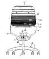
図1〜図4に示すように、この椅子は、先端部にキャスタ1を備える放射状をなす5本の脚杆2を有する脚体3を備えている。脚体3の中央には、ガススプリング(図示略)を備える伸縮式の脚柱4が立設され、脚柱4の上端には、前方を向く支基5の後部が固着されている。なお、支基5と脚柱4と脚体3とを一体化して実施してもよい。
Hereinafter, an embodiment of the present invention will be described with reference to the accompanying drawings.
As shown in FIGS. 1 to 4, the chair includes aleg body 3 having fiveleg rods 2 having a radial shape with acaster 1 at the tip. In the center of theleg 3, anextendable leg 4 having a gas spring (not shown) is erected, and the rear part of thesupport base 5 facing forward is fixed to the upper end of theleg 4. Thesupport base 5, thepedestal 4 and theleg 3 may be integrated.

支基5は、図6に示すように、前方に向かって拡開する平面視三角形の浅い皿状をなすとともに、側面視において前上方に向かって傾斜している。また、図1に示すように、支基5は、前方より見て上向きコ字状をなし、前方に開口しているので、支基5への部材の取付け作業時に、側方や後方だけでなく、前方からも部材や工具等を挿入し易いようになっている。  As shown in FIG. 6, thesupport base 5 has a shallow dish shape with a triangular shape in plan view that expands forward, and is inclined forward and upward in a side view. Further, as shown in FIG. 1, thesupport base 5 has an upward U-shape when viewed from the front and is open to the front. Therefore, when attaching the member to thesupport base 5, only the side and the rear It is easy to insert a member, a tool, etc. from the front.

座6は、合成樹脂製の座板7と、その上面に取付けられたクッション材8とからなり、座板7の前端両側部を、支基5の前端両側部に左右方向を向く枢軸9をもってそれぞれ枢着することにより、図2に示すように、後上向きに傾斜する不使用位置と、図3に示すように、水平、または後下向きに傾斜する使用位置とに、枢軸9を中心として回動可能である。この回動範囲は、ほぼ15度程度とするのが好ましい。  Theseat 6 includes aseat plate 7 made of synthetic resin and acushion material 8 attached to the upper surface of theseat 6. Theseat 6 has both front end sides on the front end of thesupport base 5 and pivots 9 facing left and right. As shown in FIG. 2, each pivotally attaches to a non-use position that tilts backward and upward as shown in FIG. 2 and a use position that tilts horizontally or rearward and downward as shown in FIG. It is possible to move. The rotation range is preferably about 15 degrees.

座6は、後述する付勢手段12により、常時不使用位置に向かって上向きに付勢されている。
図2に示すように、座6が不使用位置にあるとき、着座者が座ろうとする際に最初に当接する初期当接部Pが、脚柱4の中心線Oよりも後方に位置するようにしてある。
この初期当接部Pは、座6が使用位置にあるときは、着座者が適正な着座姿勢で着座したとき、その臀部である座骨部付近を安定よく支持する安定支持部と一致するように定めておくのが好ましい。
Theseat 6 is constantly urged upward toward the non-use position by an urging means 12 described later.
As shown in FIG. 2, when theseat 6 is in the non-use position, the initial contact portion P that first contacts when the seated person tries to sit is positioned behind the center line O of thepedestal 4. It is.
When theseat 6 is in the use position, the initial abutment portion P matches the stable support portion that stably supports the vicinity of the seat bone portion, which is the buttocks, when the seated person sits in an appropriate sitting posture. It is preferable to define it.

この初期当接部Pを、座6が不使用位置にあるとき、脚柱4の中心線Oよりも後方に位置するようにしておくと、着座者が不使用位置にある座6に着座する際に、着座者の臀部が座6の初期当接部Pに当接したとき、椅子が後方に移動するという不都合が生じるおそれはない。
また、着座者の臀部が座6の初期当接部Pに当接した後、座6は、着座者の臀部とともに、付勢手段12の付勢力に抗して使用位置まで回動し、着座者の臀部を安定支持点まで誘導して、着座者が迅速に適正な着座姿勢を取ることができるとともに、着座者の荷重が脚柱4よりも後方に加わるので、座6の後部により、着座者の臀部を安定よく支持することができる。
When the initial abutting portion P is positioned behind the center line O of thepedestal 4 when theseat 6 is in the non-use position, the seated person sits on theseat 6 in the non-use position. At this time, when the seated person's buttocks abuts against the initial abutting portion P of theseat 6, there is no possibility that the inconvenience of the chair moving backward occurs.
In addition, after the seated person's buttocks abuts against the initial abutting portion P of theseat 6, theseat 6 rotates together with the seated person's buttocks against the biasing force of the biasing means 12 to the use position. The user's buttocks are guided to the stable support point, so that the seated person can quickly take an appropriate seating posture and the seater's load is applied to the rear of thepedestal 4, so that theseat 6 is seated by the rear part of theseat 6. A person's buttocks can be supported stably.

不使用位置に位置しているときの座6の後上向き傾斜角度は、大とすればするほど、初期当接部Pが前方に移動して、脚柱4に接近するか、もしくはその前方に位置するようになるが、上記のように、初期当接部Pが、脚柱4の中心線Oよりも後方に位置するように、不使用位置に位置しているときの座6の後上向き傾斜角度を制限するのが好ましい。  The larger the rearward upward tilt angle of theseat 6 when it is in the non-use position, the more the initial contact part P moves forward and approaches thepedestal 4 or the front thereof. As described above, theseat 6 is rearwardly upward when the initial contact portion P is located at the non-use position so that it is located behind the center line O of thepedestal 4. It is preferable to limit the inclination angle.

座板7の後部両側には、背凭れ10の下部両側より前方を向く延出部10aの前部が、脚柱4の中心線Oよりも後方に位置するようにして、左右方向を向く支軸11をもってそれぞれ枢着され、背凭れ10は、図2および図3に示すように、ほぼ上方を向く起立位置と、図4に示すような後傾位置とに、支軸11を中心として回動可能である。なお、この背凭れ10およびその枢着部分の具体的な構造については、本発明と直接関係しないので、その詳細な図示および説明は省略する。  On the both sides of the rear part of theseat plate 7, the front part of the extendingpart 10 a that faces the front side from the lower side of thebackrest 10 is located behind the center line O of thepedestal 4, and is supported in the left-right direction. As shown in FIGS. 2 and 3, thebackrest 10 is pivotally attached to each other with ashaft 11, and is rotated about thesupport shaft 11 between a standing position facing upward and a rearward tilt position as shown in FIG. It is possible to move. Note that the specific structure of thebackrest 10 and the pivotally attached portion is not directly related to the present invention, and thus detailed illustration and description thereof will be omitted.

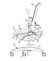
支基5には、座6の後部を上向きに付勢する付勢手段12が設けられている。
この付勢手段12は、支基5における枢軸9より下方の部分と座6における枢軸9より後方の部分とを連結する弾性伸縮手段13と、この弾性伸縮手段13の両側方において、座6の下面に前上端部が固着され、中間部が側面視において前方に向かって開口するU字状に弾性撓曲させられ、かつ前下端部が支基5における枢軸9より下方の位置に止着された左右1対の弾性撓曲手段14、14とを備えている。
Thesupport base 5 is provided with a biasing means 12 that biases the rear portion of theseat 6 upward.
The urging means 12 includes an elastic expansion / contraction means 13 for connecting a portion of thesupport base 5 below thepivot 9 and a portion of theseat 6 behind thepivot 9, and both sides of the elastic expansion / contraction means 13. The front upper end is fixed to the lower surface, the middle portion is elastically bent into a U-shape opening forward in a side view, and the front lower end is fixed at a position below thepivot 9 in thesupport base 5. A pair of left and right elastic bending means 14 and 14 are provided.

弾性伸縮手段13は、この例では、図2、図5および図6に示すように、前端部が支基5に左右方向の軸15をもって枢着され、かつ後端部が座6の下面における前後方向の中間部に左右方向の軸ピン16をもって枢着された、ロック機能のないガススプリング17としてある。しかし、ロック機能を有するガススプリングや、圧縮コイルばね、またはオイルダンパもしくはエアダンパ等とすることもできる。
ロック機能を有するガススプリングとする場合には、そのロック解除操作手段を、例えば肘掛け(図示略)の一部等に設けるのが好ましい。
In this example, as shown in FIGS. 2, 5, and 6, the elastic expansion / contraction means 13 is pivotally attached to thesupport base 5 with ashaft 15 in the left-right direction, and the rear end is on the lower surface of theseat 6. Thegas spring 17 has a locking function and is pivotally attached to a middle portion in the front-rear direction with ashaft pin 16 in the left-right direction. However, a gas spring having a lock function, a compression coil spring, an oil damper, an air damper, or the like may be used.
In the case of a gas spring having a locking function, it is preferable to provide the unlocking operation means on a part of an armrest (not shown), for example.

左右の各弾性撓曲手段14は、この例では、図5〜図8に示すように、座6の下面における両側前部に止めねじ等により止着された前後方向に長い長方形の上部取付部18aと、この上部取付部18aから後方に延出する上片18bと、上片18bの後端から前下方へ向かってほぼ半円弧状に湾曲する弾性撓曲部18cと、弾性撓曲部18cの下端から前方または前下方に延出する下片18dと、下片18dの前端に設けられ、かつ支基5に取付けるための下部取付部18eとを有する合成樹脂製の左右1対の板ばね18、18からなるものとしてある。なお、各板ばね18は、金属製としてもよい。  In this example, each of the left and right elastic bending means 14 is, as shown in FIGS. 5 to 8, a rectangular upper mounting portion which is long in the front-rear direction and is fixed to the front portions on both sides of the lower surface of theseat 6 by a set screw or the like. 18a, anupper piece 18b extending rearward from the upper mountingportion 18a, anelastic bending portion 18c that curves in a substantially semicircular arc from the rear end of theupper piece 18b toward the front lower side, and anelastic bending portion 18c A pair of left and right leaf springs made of synthetic resin having alower piece 18d extending from the lower end to the front or the front lower side, and alower attachment portion 18e provided at the front end of thelower piece 18d and attached to thesupport base 5 It consists of 18 and 18. Eachleaf spring 18 may be made of metal.

左右の板ばね18、18における両下片18d、18dの左右方向の幅は、前方に向かって漸次小としてある。これは、ガススプリング17や後述する押動杆23との干渉を避けて、座6の下方の狭い空間内に、それらを集約的に収容するためである。  The width in the left-right direction of thelower pieces 18d, 18d in the left and right leaf springs 18, 18 is gradually reduced toward the front. This is for avoiding interference with thegas spring 17 and apush rod 23 described later, and for accommodating them collectively in a narrow space below theseat 6.

また、左右の板ばね18、18は、図6に示すように、その両下片18d、18d同士が、平面視において互いに後方に向かって拡開するように配設するのが好ましい。さらに、両上片18b、18b同士も、平面視において互いに後方に向かって拡開するように配設するのが好ましい。そのようにすることによって、座6の後部を安定よく支持することができる。  Further, as shown in FIG. 6, the left andright leaf springs 18 and 18 are preferably arranged so that bothlower pieces 18 d and 18 d expand rearward in plan view. Furthermore, it is preferable that theupper pieces 18b, 18b are also arranged so as to expand toward the rear in a plan view. By doing so, the rear part of theseat 6 can be stably supported.

左右の板ばね18、18における下部取付部18e、18eは、上記軸15の両側端部に枢着されている。  Lower mountingportions 18e, 18e in the left and right leaf springs 18, 18 are pivotally attached to both side end portions of theshaft 15.

軸15は、次のようにして、支基5の前部上面に固定されている。すなわち、図5および図6に示すように、支基5における枢軸9より下方の前部の底面に、左右方向を向く凹部5aを設け、この凹部5a内に左右方向に並べて設けた複数の突部19の上面に、上方および左右両方向に開口するU字状の凹溝20をそれぞれ設け、各凹溝20に軸15を嵌合したのち、各突部19の上面に、押え金具21を、ねじ22、22をもって止着することにより、軸15は、回動不能(回動可能としてもよい)として支基5の前端部上面に固定されている。  Theshaft 15 is fixed to the front upper surface of thesupport base 5 as follows. That is, as shown in FIGS. 5 and 6, arecess 5a facing in the left-right direction is provided on the bottom surface of the front portion of thesupport base 5 below thepivot 9, and a plurality of protrusions arranged in the left-right direction in therecess 5a. The upper surface of theportion 19 is provided with U-shapedconcave grooves 20 that open in both the upper and left and right directions. By fixing with thescrews 22, 22, theshaft 15 is fixed to the upper surface of the front end portion of thesupport base 5 so as not to rotate (may be rotatable).

付勢手段12を、弾性伸縮手段13と、この弾性伸縮手段13の両側方に配設した左右1対の弾性撓曲手段14とを備えるものとしてあるので、座6の後部を、左右のバランスよく持ち上げることができるとともに、座6を安定よく支持することができる。
また、弾性伸縮手段13と弾性撓曲手段14とを、小型化して、座6の下方にコンパクトに配設することができるので、椅子の体裁をよくすることができる。
Since the biasing means 12 includes an elastic expansion / contraction means 13 and a pair of left and right elastic bending means 14 disposed on both sides of the elastic expansion / contraction means 13, the rear portion of theseat 6 is provided with a left and right balance. Theseat 6 can be lifted well and can support theseat 6 stably.
Moreover, since the elastic expansion-contraction means 13 and the elastic bending means 14 can be reduced in size and disposed compactly below theseat 6, the appearance of the chair can be improved.

上記のように、弾性伸縮手段13をガススプリング17とし、弾性撓曲手段14を板ばね18とすると、弾性伸縮手段13および弾性撓曲手段14の構造は簡素化され、安価に製造することができる。  As described above, when the elastic expansion / contraction means 13 is agas spring 17 and the elastic bending means 14 is aleaf spring 18, the structure of the elastic expansion / contraction means 13 and the elastic bending means 14 is simplified and can be manufactured at low cost. it can.

また、弾性伸縮手段13の前端部と弾性撓曲手段14の下側の前端部とを、左右方向を向く共通の軸15をもって支基5に枢着してあるから、構造を簡素化できるだけでなく、支基5への弾性伸縮手段13と弾性撓曲手段14との枢着作業を簡略化することができる。  Further, since the front end portion of the elastic expansion / contraction means 13 and the lower front end portion of the elastic bending means 14 are pivotally attached to thesupport base 5 with acommon shaft 15 facing in the left-right direction, the structure can be simplified. In addition, the pivoting operation of the elastic expansion / contraction means 13 and the elastic bending means 14 to thesupport base 5 can be simplified.

弾性撓曲手段14である板ばね18における後部の側面視半円弧状の弾性撓曲部18cの上面は、座6の下面に当接しており、座6の下向き回動時に、板ばね18における上部取付部18aと下部取付部18eとの間隔が縮まることにより、下片18dが後上方に押し出され、弾性撓曲部18cが、座6の下面に沿って漸次後方に移行するように、板ばね18は弾性変形する。
このように板ばね18が弾性変形することによって、板ばね18の同一箇所に応力が集中するのを防止し、板ばね18の耐久性を向上することができるともに、板ばね18の反力を増大させることができる。
結果的に、板ばね18の反力は、座6を下向き回動させればさせるほど大となる。
The upper surface of theelastic bending portion 18c having a semicircular arc shape when viewed from the side in theleaf spring 18 as the elastic bending means 14 is in contact with the lower surface of theseat 6, and theleaf spring 18 is rotated downward when theseat 6 is rotated downward. By reducing the distance between the upper mountingportion 18a and the lower mountingportion 18e, thelower piece 18d is pushed rearward and upward, and theelastic bending portion 18c gradually moves rearward along the lower surface of theseat 6. Thespring 18 is elastically deformed.
By elastically deforming theleaf spring 18 in this way, stress can be prevented from concentrating on the same location of theleaf spring 18 and the durability of theleaf spring 18 can be improved, and the reaction force of theleaf spring 18 can be reduced. Can be increased.
As a result, the reaction force of theleaf spring 18 increases as theseat 6 is rotated downward.

支基5における枢軸9より下方の部分と、背凭れ10における上記支軸11より下方の部分とは、前後方向を向く弾性伸縮可能の押動杆23により連結されている。
座6の不使用位置から使用位置への下向き回動時に、この押動杆23により、背凭れ10の下端部が後方に押動されて、背凭れ10は起立状態に維持され、また押動杆23が弾性収縮することにより、背凭れ10は、この押動杆23の弾性復元力に抗して、図4に示すように、後傾させることができる。
A portion of thesupport base 5 below thepivot shaft 9 and a portion of thebackrest 10 below thesupport shaft 11 are connected by an elasticallyextendable push rod 23 that faces in the front-rear direction.
When theseat 6 is pivoted downward from the non-use position to the use position, the lower end portion of thebackrest 10 is pushed backward by the pushingrod 23 so that thebackrest 10 is maintained in an upright state. As theheel 23 is elastically contracted, thebackrest 10 can be inclined backward as shown in FIG.

図6および図9〜図11に示すように、押動杆23は、前端部が弾性伸縮手段13であるガススプリング17の両側方において、左右方向の軸15により支基5に枢着された硬質かつ非可撓性の左右1対の足片23a、23aと、両足片23a、23aの後端に連設された断面円形の後方を向く左右1対の弾性撓曲部23b、23bと、ガススプリング17の下方において両足片23a、23aの後端部同士を連結する硬質かつ非可撓性の連結片23cと、両弾性撓曲部23b、23bの後端部同士を連結する硬質かつ非可撓性の連結部23dとを有する圧縮ばねにより構成してある。
連結片23cの中央部は、ガススプリング17の下面と干渉しないように、下方に凹ませてある。なお、押動杆23は、例えばポリアミド系の硬質合成樹脂により一体成形するのが好ましい。
As shown in FIGS. 6 and 9 to 11, thepush rod 23 is pivotally attached to thesupport base 5 by the left andright shafts 15 on both sides of thegas spring 17 whose front end portion is the elastic expansion / contraction means 13. A pair of left andright leg pieces 23a, 23a that are hard and inflexible, and a pair of left and rightelastic flexures 23b, 23b that are connected to the rear ends of bothleg pieces 23a, 23a and face the rear of a circular cross section; A rigid and non-flexible connectingpiece 23c that connects the rear ends of bothfoot pieces 23a and 23a below thegas spring 17 and a hard and non-flexible that connects the rear ends of bothelastic flexures 23b and 23b. It is comprised by the compression spring which has theflexible connection part 23d.
The central portion of the connectingpiece 23 c is recessed downward so as not to interfere with the lower surface of thegas spring 17. Thepush rod 23 is preferably integrally formed of, for example, a polyamide-based hard synthetic resin.

左右の足片23a、23aの前端部には、軸15に挿通される左右方向の軸孔24が形成されている。
また、後端の左右方向に幅広の連結部23dにも、左右方向を向く軸孔25が設けられ、この軸孔25には、連結部23dを、背凭れ10の下端部前面の左右方向の中央部に前向き突設された左右1対の軸受片26に枢着するための軸ピン27が挿通されている(図5参照)。
A left andright shaft hole 24 that is inserted through theshaft 15 is formed at the front end of the left andright foot pieces 23a, 23a.
The connectingportion 23d that is wide in the left-right direction at the rear end is also provided with ashaft hole 25 that faces in the left-right direction. Theshaft hole 25 is connected to the connectingportion 23d in the left-right direction on the front surface of the lower end of thebackrest 10. Ashaft pin 27 for pivotally mounting on a pair of left andright bearing pieces 26 projecting forward at the center is inserted (see FIG. 5).

左右の弾性撓曲部23b、23bは、椅子の左右方向外方に向かって概ね凸円弧状に湾曲され、かつ断面形状はほぼ円形とされている。
押動杆23における左右の弾性撓曲部23b、23bと、それらの各端部同士を連結する連結片23c、および連結部23dとにより、平面視ほぼ円形の閉ループ状に形成されている。
The left and rightelastic flexures 23b, 23b are curved in a generally convex arc shape outward in the left-right direction of the chair, and the cross-sectional shape is substantially circular.
The left and right elasticbent portions 23b and 23b of thepush rod 23, the connectingpieces 23c connecting the respective end portions, and the connectingportion 23d are formed in a closed loop shape having a substantially circular shape in plan view.

押動杆23を、両弾性撓曲部23b、23bが椅子の左右に並ぶように配設して、支基5と背凭れ10に連結することにより、背凭れ10の後傾時において、弾性撓曲部23b、23bは、図9に2点鎖線で示すように、互いに左右方向外向きに膨らむように弾性撓曲する。なお、左右の弾性撓曲部23b、23bを、上記とは反対に、互いに内向き円弧状に湾曲させて、両弾性撓曲部23bが、椅子の左右方向内方に向かって弾性撓曲するようにすることもある。  Thepush rod 23 is arranged so that bothelastic bending portions 23b and 23b are arranged on the left and right sides of the chair, and is connected to thesupport base 5 and thebackrest 10 so as to be elastic when thebackrest 10 is tilted backward. As shown by a two-dot chain line in FIG. 9, thebent portions 23b and 23b are elastically bent so as to swell outward in the left-right direction. The left and right elasticbent portions 23b and 23b are curved in an inwardly arcuate shape opposite to the above, and both elasticbent portions 23b are elastically bent inward in the left-right direction of the chair. Sometimes it does.

なお、図10に示すように、左右の弾性撓曲部23b、23bの中間部は、側面視においてわずかに下向き円弧状に湾曲され、両弾性撓曲部23bに前後方向の圧縮荷重が作用した際に、それらの中間部が、両弾性撓曲部23bを含む平面と直交する下方にも弾性変形しうるようにしてある。弾性撓曲部23bを、上記とは反対に、上向き円弧状に湾曲させてもよい。  As shown in FIG. 10, the middle part of the left and rightelastic flexures 23b, 23b is slightly curved downward in a side view, and a compressive load in the front-rear direction is applied to bothelastic flexures 23b. In this case, the intermediate portion can be elastically deformed in the lower direction perpendicular to the plane including bothelastic flexures 23b. Theelastic bending portion 23b may be curved in an upward arc shape, contrary to the above.

押動杆23として使用した圧縮ばねは、前後の両端間に前後方向の圧縮力が作用した際に、両弾性撓曲部23b、23bは、圧縮方向と直交する方向に弾性撓曲し、2部材(支基5と背凭れ10)の一方が、上記の背凭れ10のように回動しながら相対移動するものであっても、両弾性撓曲部23b、23bは効果的に弾性撓曲して、ばね力を発揮することができ、汎用性の高いものとなる。  When the compression spring used as thepush rod 23 is subjected to a longitudinal compressive force between the front and rear ends, bothelastic bending portions 23b and 23b are elastically bent in a direction perpendicular to the compression direction. Even if one of the members (thesupport base 5 and the backrest 10) moves relative to thebackrest 10 as described above, both theelastic bending portions 23b and 23b are effectively elastically bent. Thus, the spring force can be exerted, and the versatility becomes high.

また、ガススプリング等のシリンダ式の圧縮ばねに比して、構造が簡単であるため、安価で軽量感のある圧縮ばねを提供することができる。
さらに、両弾性撓曲部23b、23bと、それらの端部同士を連結する前後の硬質の連結片23cおよび連結部23dとにより、平面視円形または非円形(互いに内方に弾性撓曲させる場合等)の閉ループ状に形成されているので、弾性撓曲部23bを効果的に弾性撓曲させて、大きなばね力を得ることができ、かつ繰り返し荷重に対しても十分な強度および耐久性を有することができる。しかも、各弾性撓曲部23bをほぼ円形断面としてあるので、どのような方向にも効果的に弾性変形させることができる。
In addition, since the structure is simple compared to a cylinder-type compression spring such as a gas spring, it is possible to provide an inexpensive and lightweight compression spring.
Further, the elasticbent portions 23b and 23b and the hard connectingpieces 23c and 23d before and after connecting the end portions thereof are circular or non-circular in plan view (when elastically bending inward with respect to each other). Etc.), theelastic bending portion 23b can be effectively elastically bent to obtain a large spring force, and sufficient strength and durability against repeated loads can be obtained. Can have. Moreover, since eachelastic bending portion 23b has a substantially circular cross section, it can be effectively elastically deformed in any direction.

両弾性撓曲部23bを、それらを含む平面と直交する方向にも弾性変形しうるようにしてあるので、前後の端部間の相対移動量が大となり、背凭れ10を大きく後傾させることができる。  Since bothelastic flexures 23b can be elastically deformed in a direction perpendicular to the plane including them, the relative movement amount between the front and rear ends becomes large, and thebackrest 10 is greatly inclined backward. Can do.

上記のような圧縮ばねを、上記実施形態の椅子において支基5と背凭れ10との間に押動杆23として装着すると、背凭れ10を後傾させた際に、左右の弾性撓曲部23b、23bは、左右方向に弾性撓曲するので、支基5と座6との間に、押動杆23の上下方向の撓み空間を殆ど設ける必要がなく、座6が使用位置にあるときの高さを低く設定することができる。  When the compression spring as described above is mounted as thepush rod 23 between thesupport base 5 and thebackrest 10 in the chair of the above embodiment, when thebackrest 10 is tilted backward, the left and rightelastic flexures 23b and 23b are elastically bent in the left-right direction, so that it is not necessary to provide a vertical bending space for thepush rod 23 between thesupport base 5 and theseat 6, and when theseat 6 is in the use position. Can be set low.

また、押動杆23とした圧縮ばねは、ガススプリングやゴムトーションスプリングのような背凭れ付勢手段に比して、構造が簡単で安価であるので、椅子を軽量化することができるとともに、コスト低減が図れる。  In addition, the compression spring as thepush rod 23 is simple and inexpensive compared to a back biasing means such as a gas spring or a rubber torsion spring, so that the chair can be reduced in weight, Cost reduction can be achieved.

さらに、押動杆23は、前部の左右1対の足片23aと、後部の左右方向に幅広の連結部23dとを、それぞれ左右方向の軸15および軸ピン27をもって、支基5と背凭れ10に枢着してあるので、それを安定よく弾性変形させることができる。  Further, thepush rod 23 has a pair of left andright foot pieces 23a at the front portion and a connectingportion 23d having a wide width at the rear portion in the left-right direction, and ashaft 15 and ashaft pin 27 in the left-right direction, respectively. Since it is pivotally attached to theflange 10, it can be elastically deformed stably.

押動杆23における足片23a、23aの前端部を、弾性伸縮手段13であるガススプリング17の前端部と、弾性撓曲手段14である左右の板ばね18、18の下部取付部18e、18eとともに、左右方向を向く共通の軸15をもって支基5に枢着してあるので、構造をさらに簡素化できるだけでなく、支基5への弾性伸縮手段13と弾性撓曲手段14と押動杆23との枢着作業をさらに簡略化することができる。  The front end portions of thefoot pieces 23a, 23a of thepush rod 23 are connected to the front end portion of thegas spring 17 as the elastic expansion / contraction means 13 and thelower attachment portions 18e, 18e of the left and right leaf springs 18, 18 as the elastic bending means 14. In addition, since it is pivotally attached to thesupport base 5 with acommon shaft 15 facing in the left-right direction, not only can the structure be further simplified, but also the elastic expansion / contraction means 13, the elastic bending means 14 and the push rod to thesupport base 5. The pivoting operation with 23 can be further simplified.

次に、背凭れ10と座6との結合構造について説明する。背凭れ10は、図12に示すように、閉ループ状の背枠29と、この背枠29の表面29aに張設された張材30とを有している。背枠29の下枠部31は、平面視において前方に凹となるように湾曲することにより、その左右両側に上記延出部10aを形成する前向片32が設けられている。  Next, a connection structure between thebackrest 10 and theseat 6 will be described. As shown in FIG. 12, thebackrest 10 includes a closed loop backframe 29 and atension member 30 stretched on asurface 29 a of theback frame 29. Thelower frame portion 31 of theback frame 29 is provided withforward pieces 32 that form the extendingportions 10a on both the left and right sides thereof by being curved so as to be concave forward in plan view.

各前向片32の内面には、台座33を介して、背枠29の内方を向く比較的短い突軸34が設けら、これが支軸11をなしている。突軸34は、台座33より小径である。図13に示すように、この突軸34の内部空間には、十字形の補強リブ11aと、2個のねじ孔11b、11bとが設けられている。台座33の先端面寄りの外周面には外向突部35が設けられ、外向突部35の円周方向の一端には、台座33の中心方向に延伸する平面35aが設けられている。  A relatively short projectingshaft 34 facing inward of theback frame 29 is provided on the inner surface of eachforward piece 32 via apedestal 33, and this constitutes thesupport shaft 11. The protrudingshaft 34 has a smaller diameter than thepedestal 33. As shown in FIG. 13, a cross-shaped reinforcing rib 11 a and two screw holes 11 b and 11 b are provided in the internal space of the projectingshaft 34. Anoutward projection 35 is provided on the outer peripheral surface of thepedestal 33 near the tip surface, and aflat surface 35 a extending in the center direction of thepedestal 33 is provided at one end of theoutward projection 35 in the circumferential direction.

また、座板7の後側部には、互いに内方に向かって凹入する凹入段部36が設けられている。座板7の凹入段部36の左右方向を向く側面36aより内側の部分には、厚肉部37が設けられ、この厚肉部37に左右方向を向く嵌合孔38が設けられている。背枠29の前向片32の前縁32a、および座板7の凹入段部36における後方を向く前面36b(図14参照)は、ほぼ同一の曲率半径で湾曲形成されている。  In addition, a recessedstep 36 that is recessed inward from each other is provided on the rear side of theseat plate 7. Athick portion 37 is provided in a portion inside theside surface 36 a facing the left-right direction of the recessedstep portion 36 of theseat plate 7, and afitting hole 38 facing the left-right direction is provided in thethick portion 37. . Thefront edge 32a of theforward piece 32 of theback frame 29 and thefront surface 36b (see FIG. 14) facing rearward in the recessed steppedportion 36 of theseat plate 7 are curved with substantially the same radius of curvature.

図14に示すように、凹入段部36の側面36aには、嵌合孔38と同心かつ嵌合孔38より大径の円弧状のストッパ39が設けられている。ストッパ39の一端部には、嵌合孔38の中心方向に面する平面39aと、平面39aに対してほぼ直交する方向、すなわちストッパ39の接線方向に延びる補強リブ39bとが設けられている。  As shown in FIG. 14, anarcuate stopper 39 that is concentric with thefitting hole 38 and has a larger diameter than thefitting hole 38 is provided on theside surface 36 a of the recessedstep portion 36. One end of thestopper 39 is provided with aflat surface 39 a facing the center direction of thefitting hole 38 and a reinforcingrib 39 b extending in a direction substantially perpendicular to theflat surface 39 a, that is, a tangential direction of thestopper 39.

背凭れ10を座6に連結する場合は、図13に示すように、突軸34の外周に鍔付きスリーブ40を鍔40aが外側になるようにして嵌入し、背凭れ10の前向片32を座板7の凹入段部36内に挿入する。そして、図15に示すように、突軸34を鍔付きスリーブ40とともに、座板7の外側から嵌合孔38に嵌入する。  When connecting thebackrest 10 to theseat 6, as shown in FIG. 13, aflanged sleeve 40 is fitted on the outer periphery of the projectingshaft 34 so that theflange 40 a is outside, and theforward piece 32 of thebackrest 10 is inserted. Is inserted into the recessedstep 36 of theseat plate 7. Then, as shown in FIG. 15, the projectingshaft 34 is fitted into thefitting hole 38 together with theflanged sleeve 40 from the outside of theseat plate 7.

次に、突軸34の端面34cに、座板7の内側から嵌合孔38より大径の円板状の抜止め部材41をねじ42によって止着する。このとき、厚肉部37と抜止め部材41との間に、滑り部材43を挾むのがよい。これにより、抜止め部材41は、座板7の厚肉部37に対して回動自在に係止される。  Next, a disc-shaped retainingmember 41 having a larger diameter than thefitting hole 38 is secured to theend surface 34 c of the projectingshaft 34 from the inside of theseat plate 7 with ascrew 42. At this time, the slidingmember 43 is preferably sandwiched between thethick portion 37 and the retainingmember 41. As a result, the retainingmember 41 is pivotably locked to thethick portion 37 of theseat plate 7.

また、背枠29の前向片32を座板7の凹入段部36に挿入したときには、図16に示すように、前向片32の前縁32aと凹入段部36の前面36bとが僅かな隙間を空けて整合する。  When the forward facingpiece 32 of theback frame 29 is inserted into the recessedstep portion 36 of theseat plate 7, as shown in FIG. 16, thefront edge 32a of theforward piece 32 and thefront surface 36b of the recessedstep portion 36 Are aligned with a slight gap.

背凭れ10に後方への荷重が作用していないときには、図16に示すように、背枠29の突軸34の台座33に設けられた外向突部35の平面35aが、座板7に設けられたストッパ39の平面39aから離間している。  When no back load is applied to thebackrest 10, as shown in FIG. 16, aflat surface 35 a of theoutward projection 35 provided on thebase 33 of the projectingshaft 34 of theback frame 29 is provided on theseat plate 7. Thestopper 39 is spaced from theflat surface 39a.

背凭れ10に、着座者による後方への荷重が作用したときには、図17に示すように、背枠29が突軸34を回動中心として後方へ回動する。そして、背枠29が許容最大回動角度まで回動したとき、背枠29の外向突部35の平面35aが、座板7のストッパ39の平面39aに当接し、背凭れ10の回動が停止させられる。
外向突部35がストッパ39に当接したときの衝撃荷重は、補強リブ39bと同方向に作用するするので、ストッパ耐荷重性能が高まり、ストッパ39が破損するのを防止できる。
When a backward load is applied to thebackrest 10 by a seated person, theback frame 29 rotates backward about the protrudingshaft 34 as shown in FIG. When theback frame 29 is rotated to the maximum allowable rotation angle, theflat surface 35a of theoutward projection 35 of theback frame 29 comes into contact with theflat surface 39a of thestopper 39 of theseat plate 7, and thebackrest 10 is rotated. Be stopped.
The impact load when theoutward projection 35 abuts against thestopper 39 acts in the same direction as the reinforcingrib 39b, so that the stopper load bearing performance is enhanced and thestopper 39 can be prevented from being damaged.

背枠29と座板7とを結合した後、突軸34と嵌合孔38とによる結合部を覆うようにして、座板7にクッション材8を被覆する(図1参照)。  After theback frame 29 and theseat plate 7 are joined, thecushion material 8 is covered on theseat plate 7 so as to cover the joint portion between the protrudingshaft 34 and the fitting hole 38 (see FIG. 1).

次に、背枠29に対する張材30の張設構造について説明する。図12に示すように、背凭れ10の閉ループ状の背枠29における左右の側枠部44の間には、左右方向を向く中間連結杆45が設けられている。この中間連結杆45は、背枠29の上枠部46と下枠部31との間において、着座者の腰部に対応する位置、本実施形態では、下枠部31に比較的接近した位置に設けられている。下枠部31は、上下方向の幅が大きく、かつ比較的薄肉に形成されている。  Next, the tension structure of thetension member 30 with respect to theback frame 29 will be described. As shown in FIG. 12, an intermediate connectingrod 45 is provided between the left and rightside frame portions 44 in the closed loop backframe 29 of thebackrest 10 so as to face in the left-right direction. The intermediate connectingrod 45 is positioned between theupper frame portion 46 and thelower frame portion 31 of theback frame 29 at a position corresponding to the waist of the seated person, in the present embodiment, at a position relatively close to thelower frame portion 31. Is provided. Thelower frame portion 31 has a large vertical width and is relatively thin.

中間連結杆45は、背枠29の左右の側枠部44の内側に連結され、かつ斜め下方から後方に向かって湾曲する左右の連結部分47、47と、左右の連結部分47、47間に設けられた直線部分48とからなっている。直線部分48は、左右の側枠部41、41より後方に突出している。 The intermediate connectingrod 45 is connected to the inside of the left and rightside frame portions 44 of theback frame 29 and is curved between the left and right connectingportions 47, 47 that are curved obliquely downward and rearward. It comprises astraight portion 48 provided. Thestraight portion 48 protrudes rearward from the left and rightside frame portions 41, 41.

左右の連結部分47、47の表面47aには、湾曲面に沿って嵌合凹部49が設けられている。図18に示すように、嵌合凹部49内には、左右方向を向く位置決め用リブ50と、ねじ孔51とが設けられている。  Afitting recess 49 is provided on thesurface 47a of the left and right connectingportions 47, 47 along the curved surface. As shown in FIG. 18, positioningribs 50 and screwholes 51 facing in the left-right direction are provided in thefitting recess 49.

嵌合凹部49には、嵌合部材52が嵌合されている。この嵌合部材52の一端部には、ねじ取付け用の孔53が設けられている。また、嵌合部材52の底面52aには、嵌合凹部49の位置決め用リブ50に嵌合される位置決め用の溝54が設けられている。  Afitting member 52 is fitted in thefitting recess 49. Ascrew mounting hole 53 is provided at one end of thefitting member 52. Further, apositioning groove 54 that is fitted to thepositioning rib 50 of thefitting recess 49 is provided on thebottom surface 52 a of thefitting member 52.

図19に示すように、左右の側枠部44は、その断面形状が前後方向に細長くかつ後端部から前端部に向かって漸次厚肉になるように形成されている。左右の側枠部44の中間連結杆45より上側の部分における表面44a寄りの外周面44bには、長手方向を向く凹溝55が外側に向けて開口するようにして設けられている。この凹溝55は、上枠部46の表面46a寄りの外周面46bにも設けられている。左右の側枠部44における凹溝55の長手方向における端縁の開口は、図18に示すように、中間連結杆45における連結部分48の嵌合凹部49内に向かって開口している。  As shown in FIG. 19, the left and rightside frame portions 44 are formed so that the cross-sectional shape is elongated in the front-rear direction and gradually becomes thicker from the rear end portion toward the front end portion. On the outerperipheral surface 44b near thesurface 44a in the portion above the intermediate connectingrod 45 of the left and rightside frame portions 44, aconcave groove 55 facing the longitudinal direction is provided so as to open outward. Theconcave groove 55 is also provided on the outerperipheral surface 46 b near thesurface 46 a of theupper frame portion 46. The opening of the edge in the longitudinal direction of theconcave groove 55 in the left and rightside frame portions 44 opens toward the fittingconcave portion 49 of the connectingportion 48 in the intermediate connectingrod 45 as shown in FIG.

図20に示すように、嵌合凹部49に嵌合された嵌合部材52の表面52b(図18参照)寄りの外周面52cには、外周側に開口するようにして凹溝56が設けられている。嵌合部材52の凹溝56は、嵌合凹部49内に開口している左右の側枠部44の凹溝55(図18参照)に連続している。  As shown in FIG. 20, aconcave groove 56 is provided on the outerperipheral surface 52c near thesurface 52b (see FIG. 18) of thefitting member 52 fitted in the fittingconcave portion 49 so as to open to the outer peripheral side. ing. Theconcave groove 56 of thefitting member 52 is continuous with the concave groove 55 (see FIG. 18) of the left and rightside frame portions 44 opened in the fittingconcave portion 49.

中間連結杆45の直線部分48は、図21に示すように、その断面形状が前後方向に細長く形成されている。この直線部分48の表面48a寄りの外周面48b側には、下方に向かって突出する長手方向を向く突条48cが設けられている。この突条48cの裏面側に、長手方向を向く凹溝57が設けられている。この凹溝57は、直線部分48と連結部分47との境界付近まで延びている。  As shown in FIG. 21, thestraight portion 48 of the intermediate connectingrod 45 has a cross-sectional shape that is elongated in the front-rear direction. On the outerperipheral surface 48b side of thestraight portion 48 near thesurface 48a, aridge 48c facing in the longitudinal direction and projecting downward is provided. Aconcave groove 57 facing the longitudinal direction is provided on the back surface side of theprotrusion 48c. Theconcave groove 57 extends to the vicinity of the boundary between thelinear portion 48 and the connectingportion 47.

図12に示すように、背凭れ10の張材30は、メッシュ材料によって伸縮可能に形成されている。この張材30の周縁部30aは袋状に形成され、その中に縁材58(図19参照)が挿入されて縫着されている。縁材58は、弾性を有する合成樹脂により細長い平板状に形成されている。  As shown in FIG. 12, theupholstery material 30 of thebackrest 10 is formed to be stretchable by a mesh material. Theperipheral edge portion 30a of thetension member 30 is formed in a bag shape, and an edge member 58 (see FIG. 19) is inserted and sewn therein. Theedge member 58 is formed in an elongated flat plate shape from a synthetic resin having elasticity.

張材30を背枠29の表面側に張設する場合は、図20に示すように、中間連結杆45の嵌合凹部49に嵌合部材52を嵌合し、それぞれねじによって止着する。  When thetension member 30 is stretched on the surface side of theback frame 29, as shown in FIG. 20, thefitting member 52 is fitted into thefitting recess 49 of the intermediate connectingrod 45, and each is fastened with screws.

次に、周縁部30aに縁材58を縫着した張材30を、背枠29の中間連結杆45より上の左右の側枠部44の表面44a側、および上枠部46の表面46a側に被せた後、図19中に想像線で示すように、張材30の縁材58を適度な力で側枠部44の外周面44b側に引張する。次に、図19中に実線で示すように、縁材58を凹溝55に挿入する。同様にして、上枠部46の凹溝55および嵌合部材52の凹溝56にも張材30の周縁部30aにおける縁材58を挿入する。また、中間連結杆45の直線部分48の凹溝57は、後方に向かって開口しているので、張材30の下部を中間連結杆45の下面に沿って後方に引き出した後、下方の縁材58を凹溝57の後方から挿入する。  Next, theupholstery material 30 in which theedge member 58 is sewn to theperipheral edge portion 30a is attached to thesurface 44a side of the left and rightside frame portions 44 above theintermediate coupling bar 45 of theback frame 29 and thesurface 46a side of theupper frame portion 46. Then, as shown by an imaginary line in FIG. 19, theedge member 58 of thetension member 30 is pulled toward the outerperipheral surface 44b of theside frame portion 44 with an appropriate force. Next, as shown by a solid line in FIG. 19, theedge member 58 is inserted into theconcave groove 55. Similarly, theedge member 58 at theperipheral edge 30 a of thetension member 30 is inserted into thegroove 55 of theupper frame portion 46 and thegroove 56 of thefitting member 52. Further, since theconcave groove 57 of thestraight portion 48 of the intermediate connectingrod 45 opens rearward, after the lower portion of thetension member 30 is pulled out rearward along the lower surface of the intermediate connectingrod 45, the lower edge Thematerial 58 is inserted from behind theconcave groove 57.

それにより、縁材58は、張材30の張力によって背枠29の中間連結杆45より上の側枠部44および上枠部46の表面側に引張され、縁材58は凹溝55、56に係合される。これにより、張材30は背枠29における上枠部46、左右の側枠部44および中間連結杆45のそれぞれの表面側に張設された状態で維持される。また、中間連結杆45と下枠部31との間には、張材30が張設されていないので、図1に示すように、背凭れ10と座6との間には前後に連通する隙間59が形成される。  Thereby, theedge member 58 is pulled to the surface side of theside frame portion 44 and theupper frame portion 46 above theintermediate coupling rod 45 of theback frame 29 by the tension of thetension member 30, and theedge member 58 is recessed into thegrooves 55 and 56. Is engaged. As a result, thetension member 30 is maintained in a state of being stretched on the respective surface sides of theupper frame portion 46, the left and rightside frame portions 44, and the intermediate connectingrod 45 in theback frame 29. Further, since thetension member 30 is not stretched between the intermediate connectingrod 45 and thelower frame portion 31, as shown in FIG. 1, thebackrest 10 and theseat 6 communicate with each other in the front-rear direction. Agap 59 is formed.

以上のような構成とした椅子は、図2に示す不使用状態では、付勢手段12の付勢力によって、座6の後部が上方に持ち上げられ、座6は後上向き傾斜する不使用位置に位置しており、背凭れ10は、押動杆23の伸長により、ほぼ上方を向く起立位置に保持されている。  In the non-use state shown in FIG. 2, the chair configured as described above is lifted upward by the urging force of the urging means 12, and theseat 6 is positioned at a non-use position where theseat 6 inclines rearward upward. Thebackrest 10 is held in an upright position substantially facing upward by the extension of thepush rod 23.

この状態で、着座者が着座しようとすると、まず着座者の臀部が、上述したように座6の初期当接部Pに当接し、座6は着座者の臀部とともに、付勢手段12の付勢力に抗して、図3に示す使用位置まで回動させられ、着座者の臀部を安定支持点まで誘導し、着座者は迅速に適正な着座姿勢を取ることができる。  In this state, when the seated person tries to sit down, the seated person's buttocks first come into contact with the initial contact part P of theseat 6 as described above, and theseat 6 together with the seated person's buttocks is attached to the biasing means 12. It is rotated to the use position shown in FIG. 3 against the force, and the seat occupant's buttocks are guided to the stable support point, so that the seat occupant can quickly take an appropriate seating posture.

図3に示す着座状態から、着座者が背中を背凭れ10に凭せかけて背を後方に倒すと、背凭れ10は、押動杆23を弾性収縮させつつ、支軸11を中心として、図4に示すような後傾位置まで回動させられる。この押動杆23の弾性収縮の初期に、硬質の連結部23dが軸ピン27により前方に押動され、そのときの左右の弾性撓曲部23b、23bにおける連結部23dへの結合部分が若干上下方向に捩れつつ、弾性撓曲部23b、23b全体が、図9に2点鎖線で示すように、互いに左右方向外向きに膨らむように弾性撓曲するとともに、上下方向にも若干蛇行するように弾性変形する。
When the seated person leans back on thebackrest 10 and tilts the back backward from the sitting state shown in FIG. 3, thebackrest 10 is elastically contracted by thepush rod 23, and thesupport shaft 11 is centered. It is rotated to a rearward tilt position as shown in FIG. At the initial stage of the elastic contraction of thepush rod 23, the hard connectingportion 23d is pushed forward by theshaft pin 27, and at this time, the left and right elasticbent portions 23b, 23b are slightly connected to the connectingportion 23d. While being twisted in the vertical direction, the entireelastic bending portions 23b, 23b are elastically bent so as to bulge outward in the left-right direction as shown by a two-dot chain line in FIG. 9, and slightly meander in the vertical direction. It is elastically deformed.
y

着座者が背中を前方に戻すと、背凭れ10は、押動杆23の弾性復元力による伸長によって、支軸11を中心として前方に回動させられ、元の起立位置まで戻される。  When the seated person returns his / her back to the front, thebackrest 10 is rotated forward about thesupport shaft 11 by the extension by the elastic restoring force of thepush rod 23 and returned to the original standing position.

図3に示す着座状態から、着座者が立上がろうとすると、座6は、弾性伸縮手段13と弾性撓曲手段14との相乗作用により、不使用位置に向かって上向き回動するように付勢され、着座者の起立をアシストすることができる。  When the seated person tries to stand up from the seating state shown in FIG. 3, theseat 6 is attached so as to rotate upward toward the non-use position by the synergistic action of the elastic expansion / contraction means 13 and the elastic bending means 14. The seated person can be assisted in standing up.

また、この椅子によれば、次のような効果を奏することができる。
(a)座6の上方への付勢手段として板ばね18が用いられているので、付勢手段の構成を簡略化でき、コストダウンが可能になる。
また、板ばね18により、座6の下面における枢軸9より離れた部分を持ち上げることができるので、座6の後部を持ち上げる力を大きくできる。したがって、座6の起立支援効果を向上させることができる。
Moreover, according to this chair, there can exist the following effects.
(a) Since theleaf spring 18 is used as the urging means upward of theseat 6, the structure of the urging means can be simplified and the cost can be reduced.
In addition, since theplate spring 18 can lift the portion of the lower surface of theseat 6 away from thepivot 9, the force for lifting the rear portion of theseat 6 can be increased. Therefore, the standing support effect of theseat 6 can be improved.

(b)板ばね18を中間部で折り返すので、小型化できる。また、板ばね18の座6に固着された部分から、支基5に止着された部分までの長さを大とすることができるので、板ばね18の可動範囲を広くできるとともに、板ばね18の構造を簡略化することができる。
また、座6の下向き回動時に、弾性撓曲部18cが座6の下面に沿って漸次後方に移行するように弾性変形することによって、板ばね18による座6の上向付勢力は、座6の回動範囲のどの位置にあってもほぼ均一となる。
(b) Since theleaf spring 18 is folded back at the intermediate portion, the size can be reduced. Further, since the length from the portion fixed to theseat 6 of theleaf spring 18 to the portion fixed to thesupport base 5 can be increased, the movable range of theleaf spring 18 can be widened, and the leaf spring can be increased. The structure of 18 can be simplified.
Further, when theseat 6 is turned downward, theelastic bending portion 18c is elastically deformed so as to gradually move rearward along the lower surface of theseat 6, whereby the upward biasing force of theseat 6 by theleaf spring 18 is increased. 6 is almost uniform at any position in the rotation range.

(c)板ばね18の下片18dにおける左右方向の幅を、前方に向かって漸次狭くしたので、板ばね18の下片18dの周囲のスペースを広くでき、このスペースに他の部品を収容することができる。(c) Since the width in the left-right direction of thelower piece 18d of theleaf spring 18 is gradually narrowed toward the front, the space around thelower piece 18d of theleaf spring 18 can be widened, and other parts are accommodated in this space. be able to.

(d)付勢手段を、座6の下方に設けた左右1対の板ばね18からなるものとしたので、左右の板ばね18、18によって座6を安定よく支持できるとともに、座6の付勢力を大とすることができる。(d) Since the urging means is composed of a pair of left and right leaf springs 18 provided below theseat 6, theseat 6 can be stably supported by the left and right leaf springs 18, 18, and The power can be increased.

(e)左右の板ばね18、18を、平面視において互いに後方に向かって拡開するように配設したので、左右の板ばね18、18によって、座6の後部を安定よく支持できる。(e) Since the left and right leaf springs 18, 18 are arranged so as to expand rearward in plan view, the left and right leaf springs 18, 18 can stably support the rear portion of theseat 6.

本発明は、上記実施形態のみに限定されるものではなく、特許請求の範囲を逸脱しない範囲で、幾多の変形した態様での実施が可能である。
例えば、板ばね18を、1個または3個以上設けてもよい。
The present invention is not limited to the above-described embodiment, and can be implemented in various modified forms without departing from the scope of the claims.
For example, one or three ormore leaf springs 18 may be provided.

1 キャスタ
2 脚杆
3 脚体
4 脚柱
5 支基
5a 凹部
6 座
7 座板
8 クッション材
9 枢軸
10 背凭れ
10a延出部
11 支軸
11a 補強リブ
11b ねじ孔
12 付勢手段
13 弾性伸縮手段
14 弾性撓曲手段
15 軸
16 軸ピン
17 ガススプリング
18 板ばね
18a上部取付部
18b上片
18c弾性撓曲部
18d下片
18e下部取付部
19 凸部
20 凹溝
21 押え金具
22 ねじ
23 押動杆(圧縮ばね)
23a足片(硬質部)
23b弾性撓曲部
23c連結片(硬質部)
23d連結部(硬質部)
24、25 軸孔
26 軸受片
27 軸ピン
29 枠体
29a 表面
30 張材
31 下枠部
32 前向片
32a 前縁
33 台座
34 突軸
34c 端面
35 外向突部
35a 平面
36 凹入段部
36a 側面
36b 前面
37 厚肉部
38 嵌合孔
39 ストッパ
39a 平面
39b 補強リブ
40 鍔付きスリーブ
40a 鍔
41 抜止め部材
42 ねじ
43 滑り部材
44 側枠部
45 中間連結杆
45a 表面
45b外周面
46 上枠部
46a 表面
46b外周面
47 連結部分
47a 表面
48 直線部分
48a 表面
48b 外周面
48c 突条
49 嵌合凹部
50 位置決め用リブ
51 ねじ孔
52 嵌合部材
52a 底面
52b 表面
52c 外周面
53 孔
54 溝
55 凹溝
56 凹溝
57 凹溝
58 縁材
59 隙間
DESCRIPTION OFSYMBOLS 1Caster 2Leg rod 3Leg 4Leg column 5Supportbase 5a Recess 6Seat 7Seat plate 8Cushion material 9Axle 10Backrest10a Extension part 11 Support shaft 11a Reinforcement rib11b Screw hole 12 Biasing means 13 Elastic expansion / contraction means 14 elastic bending means 15shaft 16shaft pin 17gas spring 18leaf spring 18a upper mountingportion 18bupper piece 18celastic bending portion 18dlower piece 18e lower mountingportion 19convex portion 20concave groove 21 presser fitting 22screw 23 push rod (Compression spring)
23a foot piece (hard part)
23belastic bending part 23c connection piece (hard part)
23d connecting part (hard part)
24, 25Shaft hole 26Bearing piece 27Shaft pin 29Frame 29a Surface 30Upholstery material 31Lower frame portion 32Front piece32a Front edge 33Base 34Projection shaft34c End surface 35Outward projection 35aFlat surface 36 Recessedstep portion36a Side surface36b Front surface 37Thick wall portion 38Fitting hole 39Stopper 39aFlat surface39b Reinforcement rib 40Ribbed sleeve 40a 鍔 41Detachment member 42Screw 43 Slidingmember 44Side frame portion 45 Intermediate connecting rod 45a Surface 45b Outerperipheral surface 46Upper frameportion 46a Surface 46b outerperipheral surface 47Connectingportion 47a Surface 48Linearportion 48a Surface 48b Outerperipheralsurface 48c Projection 49Fitting recess 50Positioning rib 51Screw hole 52Fitting member52a Bottomsurface 52b Surface 52c Outerperipheral surface 53Hole 54Groove 55Groove 56Groove 57Groove 58Edge material 59 Clearance

Claims (5)

Translated fromJapanese
脚によって支持された支基に、座の前部を左右方向を向く枢軸をもって枢着することにより、後部が上下方向に回動可能とし、前記支基に、座における枢軸よりも後部を上向きに付勢する付勢手段を設けた椅子において、
前記付勢手段を、座の下面に一端部が止着され、中間部が座の後部下面に当接するようにして、前下方へ向かって弾性撓曲させられ、かつ他端が前記支基における枢軸より下方の部分に止着された板ばねよりなるものとしたことを特徴とする椅子。
By pivotally attachingthe front part of the seat to the support base supported by the legs with a pivot that faces in the left-right direction, the rear part can be turned up and down, and the rear part is directed upward from the pivot in the seat. In a chair provided with a biasing means for biasing,
The biasing means is elastically bentforward and downward so that one end portion is fixed to the lower surface of the seat, the middle portion isin contact with the lower surface of the rear portion of theseat , and the other end is in the support base. A chair comprising a leaf spring fixed to a portion below the pivot.
脚によって支持された支基に、座を左右方向を向く枢軸をもって枢着することにより、後部が上下方向に回動可能とし、前記支基に、座における枢軸よりも後部を上向きに付勢する付勢手段を設けた椅子において、
前記付勢手段を、座の下面に一端部が止着され、中間部が弾性撓曲させられ、かつ他端が前記支基における枢軸より下方の部分に止着された板ばねよりなるものとし、かつ前記板ばねが、座に固着された上部取付部から後方を向く上片と、上片の後端から下方にほぼ半円弧状に湾曲し、かつ上端が座の下面に当接するようにした弾性撓曲部と、この弾性撓曲部の下端から前方または前下方を向く下片と、下片の前端に設けられ、かつ支基に取付けられる下部取付部とからなり、側面視において前方に向かって開口するU字状に弾性撓曲させられたものとしたことを特徴とする椅子。
By pivotally attaching the seat to the support base supported by the legs with a pivot that faces in the left-right direction, the rear part can be rotated in the vertical direction, and the rear part is biased upward from the pivot in the seat. In a chair provided with a biasing means,
The urging means is composed of a leaf spring having one end fixed to the lower surface of the seat, an intermediate portion elastically bent, and the other end fixed to a portion below the pivot of the support base. And the leaf spring is curved in a substantially semicircular arc downward from the rear end of the upper piece, and the upper end is in contact with the lower surface of the seat. An elastic bending portion, a lower piece facing forward or lower front from the lower end of the elastic bending portion, and a lower mounting portion provided at the front end of the lower piece and attached to the support base, and viewed from the front in a side viewA chaircharacterized by being elastically bent into a U-shape opening toward the top.
下片における左右方向の幅を、前方に向かって漸次狭くした請求項2記載の椅子。The chair according to claim2 , wherein the width of the lower piece in the left-right direction is gradually narrowed toward the front. 付勢手段を、座の下方に設けた左右1対の板ばねからかるものとした請求項1〜3のいずれかに記載の椅子。The chair according toany one of claims 1 to3 , wherein the urging means is a pair of left and right leaf springs provided below the seat. 左右の板ばねを、平面視において互いに後方に向かって拡開するように配設した請求項4記載の椅子。  The chair according to claim 4, wherein the left and right leaf springs are disposed so as to expand rearward in a plan view.
JP2010133749A2010-06-112010-06-11 ChairActiveJP5616133B2 (en)

Priority Applications (7)

Application NumberPriority DateFiling DateTitle
JP2010133749AJP5616133B2 (en)2010-06-112010-06-11 Chair
CA2802187ACA2802187A1 (en)2010-06-112011-06-09Chair
CN201180028517.6ACN102946762B (en)2010-06-112011-06-09Chair
US13/703,182US20130169017A1 (en)2010-06-112011-06-09Chair
PCT/JP2011/063231WO2011155557A1 (en)2010-06-112011-06-09Chair
KR1020127032777AKR20130111950A (en)2010-06-112011-06-09Chair
EP11792514.9AEP2580993A4 (en)2010-06-112011-06-09Chair

Applications Claiming Priority (1)

Application NumberPriority DateFiling DateTitle
JP2010133749AJP5616133B2 (en)2010-06-112010-06-11 Chair

Publications (2)

Publication NumberPublication Date
JP2011255072A JP2011255072A (en)2011-12-22
JP5616133B2true JP5616133B2 (en)2014-10-29

Family

ID=45471920

Family Applications (1)

Application NumberTitlePriority DateFiling Date
JP2010133749AActiveJP5616133B2 (en)2010-06-112010-06-11 Chair

Country Status (1)

CountryLink
JP (1)JP5616133B2 (en)

Family Cites Families (2)

* Cited by examiner, † Cited by third party
Publication numberPriority datePublication dateAssigneeTitle
DE1294617B (en)*1964-04-241969-05-08Holmstroem Erik Folke Springy chair
JPH07246123A (en)*1994-03-081995-09-26Inoue Assoc:KkSwinging mechanism for seat plate and back rest of chair

Also Published As

Publication numberPublication date
JP2011255072A (en)2011-12-22

Similar Documents

PublicationPublication DateTitle
WO2011155557A1 (en)Chair
WO2010044331A1 (en)Chair
KR101928964B1 (en)Folding type chair with sliding seat
JP6527623B1 (en) Chair
JP7735142B2 (en) chair
JP5567402B2 (en) Chair
JP5460997B2 (en) Hinge structure and chair back support structure using it
JP5479801B2 (en) Back support structure
JP7735143B2 (en) chair
JP5616133B2 (en) Chair
JP2013000446A (en)Chair
JP7750705B2 (en) chair
JP5632204B2 (en) Chair
JP5620158B2 (en) Chair back
JP5616134B2 (en) Chair
JP5576186B2 (en) Chair
JP5630810B2 (en) Compression spring and chair provided with the same
JP2013000445A (en)Chair
JP5576187B2 (en) Chair
JP2018057639A (en)Chair
JP2011092475A (en)Rocking chair
JP6777281B2 (en) Chair
JP4486465B2 (en) Chair backrest mounting structure
JP5479800B2 (en) Seat backrest mounting structure
JP5650491B2 (en) Chair

Legal Events

DateCodeTitleDescription
A621Written request for application examination

Free format text:JAPANESE INTERMEDIATE CODE: A621

Effective date:20130607

A131Notification of reasons for refusal

Free format text:JAPANESE INTERMEDIATE CODE: A131

Effective date:20140527

A521Request for written amendment filed

Free format text:JAPANESE INTERMEDIATE CODE: A523

Effective date:20140724

TRDDDecision of grant or rejection written
A01Written decision to grant a patent or to grant a registration (utility model)

Free format text:JAPANESE INTERMEDIATE CODE: A01

Effective date:20140812

A61First payment of annual fees (during grant procedure)

Free format text:JAPANESE INTERMEDIATE CODE: A61

Effective date:20140911

R150Certificate of patent or registration of utility model

Ref document number:5616133

Country of ref document:JP

Free format text:JAPANESE INTERMEDIATE CODE: R150

R250Receipt of annual fees

Free format text:JAPANESE INTERMEDIATE CODE: R250

R250Receipt of annual fees

Free format text:JAPANESE INTERMEDIATE CODE: R250

S533Written request for registration of change of name

Free format text:JAPANESE INTERMEDIATE CODE: R313533

R350Written notification of registration of transfer

Free format text:JAPANESE INTERMEDIATE CODE: R350

R250Receipt of annual fees

Free format text:JAPANESE INTERMEDIATE CODE: R250

R250Receipt of annual fees

Free format text:JAPANESE INTERMEDIATE CODE: R250

R250Receipt of annual fees

Free format text:JAPANESE INTERMEDIATE CODE: R250

R250Receipt of annual fees

Free format text:JAPANESE INTERMEDIATE CODE: R250

R250Receipt of annual fees

Free format text:JAPANESE INTERMEDIATE CODE: R250

R250Receipt of annual fees

Free format text:JAPANESE INTERMEDIATE CODE: R250

R250Receipt of annual fees

Free format text:JAPANESE INTERMEDIATE CODE: R250


[8]ページ先頭

©2009-2025 Movatter.jp