JP5615112B2 - Organ fixing device and organ fixing device - Google Patents
Organ fixing device and organ fixing deviceDownload PDFInfo
- Publication number
- JP5615112B2 JP5615112B2JP2010210530AJP2010210530AJP5615112B2JP 5615112 B2JP5615112 B2JP 5615112B2JP 2010210530 AJP2010210530 AJP 2010210530AJP 2010210530 AJP2010210530 AJP 2010210530AJP 5615112 B2JP5615112 B2JP 5615112B2
- Authority
- JP
- Japan
- Prior art keywords
- rod
- thread
- organ fixing
- organ
- fixing device
- Prior art date
- Legal status (The legal status is an assumption and is not a legal conclusion. Google has not performed a legal analysis and makes no representation as to the accuracy of the status listed.)
- Expired - Fee Related
Links
Images


Classifications
- A—HUMAN NECESSITIES
- A61—MEDICAL OR VETERINARY SCIENCE; HYGIENE
- A61B—DIAGNOSIS; SURGERY; IDENTIFICATION
- A61B17/00—Surgical instruments, devices or methods
- A61B17/04—Surgical instruments, devices or methods for suturing wounds; Holders or packages for needles or suture materials
- A61B17/0482—Needle or suture guides
- A—HUMAN NECESSITIES
- A61—MEDICAL OR VETERINARY SCIENCE; HYGIENE
- A61B—DIAGNOSIS; SURGERY; IDENTIFICATION
- A61B17/00—Surgical instruments, devices or methods
- A61B17/04—Surgical instruments, devices or methods for suturing wounds; Holders or packages for needles or suture materials
- A61B17/0401—Suture anchors, buttons or pledgets, i.e. means for attaching sutures to bone, cartilage or soft tissue; Instruments for applying or removing suture anchors
- A61B2017/0409—Instruments for applying suture anchors
- A—HUMAN NECESSITIES
- A61—MEDICAL OR VETERINARY SCIENCE; HYGIENE
- A61B—DIAGNOSIS; SURGERY; IDENTIFICATION
- A61B17/00—Surgical instruments, devices or methods
- A61B17/04—Surgical instruments, devices or methods for suturing wounds; Holders or packages for needles or suture materials
- A61B17/0401—Suture anchors, buttons or pledgets, i.e. means for attaching sutures to bone, cartilage or soft tissue; Instruments for applying or removing suture anchors
- A61B2017/0417—T-fasteners
- A—HUMAN NECESSITIES
- A61—MEDICAL OR VETERINARY SCIENCE; HYGIENE
- A61B—DIAGNOSIS; SURGERY; IDENTIFICATION
- A61B17/00—Surgical instruments, devices or methods
- A61B17/04—Surgical instruments, devices or methods for suturing wounds; Holders or packages for needles or suture materials
- A61B17/0469—Suturing instruments for use in minimally invasive surgery, e.g. endoscopic surgery
- A61B2017/0472—Multiple-needled, e.g. double-needled, instruments
- A—HUMAN NECESSITIES
- A61—MEDICAL OR VETERINARY SCIENCE; HYGIENE
- A61B—DIAGNOSIS; SURGERY; IDENTIFICATION
- A61B17/00—Surgical instruments, devices or methods
- A61B17/04—Surgical instruments, devices or methods for suturing wounds; Holders or packages for needles or suture materials
- A61B17/06—Needles ; Sutures; Needle-suture combinations; Holders or packages for needles or suture materials
- A61B2017/06052—Needle-suture combinations in which a suture is extending inside a hollow tubular needle, e.g. over the entire length of the needle
Landscapes
- Surgical Instruments (AREA)
Description
Translated fromJapanese本発明は、胃や膀胱等の内蔵壁を、体外から腹壁側に吊り上げて保持する臓器固定具及びこの臓器固定具の導入具に関する。 The present invention relates to an organ fixing tool for holding a built-in wall such as a stomach or a bladder from the outside of the body to the abdominal wall side and an introducing tool for the organ fixing tool.
例えば経皮内視鏡的胃瘻造設術(PEG;Percutaneous Endoscopic Gastrostomy)により胃瘻を造設する場合などには、患者の腹壁と内臓壁とを貫通する貫通孔を形成する必要がある。そして、この貫通孔の形成を容易に行うため、動きやすい内臓壁を腹壁に固定する技術が提案されている。 For example, when a gastrostomy is constructed by percutaneous endoscopic gastrostomy (PEG), it is necessary to form a through-hole penetrating the patient's abdominal wall and visceral wall. And in order to perform this through-hole formation easily, the technique which fixes the internal organ wall which is easy to move to an abdominal wall is proposed.
従来、内臓壁と腹壁とを固定する技術として、「縫合系挿入用穿刺針と、該縫合系挿入用穿刺針より所定距離離間して、ほぼ平行に設けられた縫合系把持用穿刺針と、該縫合系把持用穿刺針内部に摺動可能に挿入されたスタイレットと、前記縫合系挿入用穿刺針および前記縫合系把持用穿刺針の基端部が固定された固定部材」とからなる内臓固定具が提案されている(例えば、特許文献1参照)。 Conventionally, as a technique for fixing the visceral wall and the abdominal wall, `` a puncture needle for inserting a suture system, and a puncture needle for grasping a suture system provided substantially in parallel with a predetermined distance from the puncture needle for inserting a suture system; A viscera comprising a stylet slidably inserted into the suturing system grasping puncture needle, and a fixing member to which the suturing system insertion puncture needle and the proximal end of the suturing system grasping puncture needle are fixed. A fixture has been proposed (see, for example, Patent Document 1).
また、他の技術として、いわゆる「Tファスナー」を用いた臓器固定技術がある。このTファスナーを用いる場合には、Tファスナーの導入具である中空の穿刺針にTファスナーを内装し、この穿刺針を腹壁と内臓壁に順に穿刺する。そして、内臓壁内でTファスナーを穿刺針から放出して穿刺針のみを抜去する。このようにすると、Tファスナーが内臓壁内に残り、Tファスナーの糸を体表側から牽引することで、内臓壁と腹壁とを固定することができる(例えば、特許文献2参照)。 As another technique, there is an organ fixing technique using a so-called “T fastener”. When using this T-fastener, the T-fastener is housed in a hollow puncture needle that is an introduction tool for the T-fastener, and the puncture needle is punctured in order on the abdominal wall and the visceral wall. Then, the T fastener is released from the puncture needle within the visceral wall, and only the puncture needle is removed. If it does in this way, a T fastener will remain in a visceral wall, and a visceral wall and an abdominal wall can be fixed by pulling the thread | yarn of a T fastener from the body surface side (for example, refer patent document 2).
特許文献1に記載の内臓固定具を用いる場合には、2本の穿刺針を使用して内臓壁内で縫合糸の受け渡しを行い、体表側に取り出された縫合糸の両端を結紮することにより、内臓壁と腹壁とを固定する。このような手技は手順が多く煩雑であるので、技術の熟練に時間を要していた。 When using the visceral fixing device described in
また、特許文献2に記載のTファスナーを用いる場合、内臓壁の固定が不要になるとTファスナーの糸を切断してTファスナーのロッドを胃等の内臓内に落下させる。このため、内臓内に落下したロッドは、排泄されるまで体内に残留することとなる。内臓内に落下させたロッドを、例えば内視鏡を用いて回収することも可能であるが、術者の手間がかかるとともに、侵襲も多く患者の負担が大きかった。 When the T fastener described in
また、内臓壁を効果的に固定するためには複数点で固定する必要があり、例えば胃壁を固定する場合には4点で固定するのが通常である。このため、特許文献1、2のいずれの技術を用いる場合も、同じ手技を4回繰り返す必要があり、手技に時間と手間を要していた。 Further, in order to effectively fix the visceral wall, it is necessary to fix it at a plurality of points. For example, when fixing the stomach wall, it is usually fixed at four points. For this reason, when using any technique of
本発明は、上記のような課題を解決するためになされたものであり、より簡単な手技で短時間に臓器を固定することができ、また、使用済みの臓器固定具を容易に回収することができる臓器固定具を提供するものである。また、この臓器固定具の導入具を提供するものである。 The present invention has been made to solve the above-described problems, and can fix an organ in a short time with a simpler technique, and can easily collect a used organ fixing device. It is intended to provide an organ fixing tool that can be used. Moreover, the introduction tool of this organ fixing tool is provided.
本発明に係る臓器固定具の導入具は、第一ロッド及び第二ロッドと、一端が第一ロッドの軸方向略中央位置に接続され、他端が第二ロッドの軸方向略中央位置に接続されていて、第一ロッドと第二ロッドとを連結する吊り上げ糸と、第一ロッドの軸方向一端に連結された第一引き出し糸と、第二ロッドの軸方向一端に連結された第二引き出し糸とを備えた臓器固定具の導入具であって、内腔を有する2本の穿刺針と、2本の穿刺針をほぼ平行に所定距離離間させて保持する針保持部材と、2本の穿刺針の内腔を貫通自在な2本の押し出し棒の上部を連結して構成された押し出し部材とを備えたものである。The organ fixing deviceintroducer according to the present invention has a first rod and a second rod, one end connected to the substantially central position in the axial direction of the first rod, and the other end connected to a substantially central position in the axial direction of the second rod. A lifting thread connecting the first rod and the second rod, a first pulling thread connected to one axial end of the first rod, and a second pulling connected to one axial end of the second rod Anorgan fixing device including a thread, two puncture needles having a lumen, a needle holding member that holds the two puncture needles at a predetermined distance from each other, and two And an extruding member configured by connecting upper portions of two extruding rods that can penetrate the lumen of the puncture needle .
本発明に係る臓器固定具の導入具は、臓器固定具のロッドが中空部材で構成され、臓器固定具のロッドの中空部内で吊り上げ糸と2本の引き出し糸とを接続することにより、2本の引き出し糸と吊り上げ糸とが1本の糸部材で構成されているものである。Introducer of organ-fixing instrument pertaining to the present invention, the rodof the organ-fixing instrumentis constituted by a hollow member, connects the lifting yarn and a pull-out string of two within the hollow portion of the rodof the organ-fixing instrument, two and pull-out string with lifting yarnis onethat is composed of one thread member.
本発明に係る臓器固定具の導入具は、臓器固定具が、吊り上げ糸の長さを調節する長さ調節機構を備えたものである。The organ fixing toolintroduction tool according to the present invention is anorgan fixing tool provided with a length adjusting mechanism for adjusting the length ofthe lifting thread.
本発明に係る臓器固定具の導入具は、穿刺針の先端から送り出された糸を、穿刺針の先端よりも基端側の位置で保持する糸かけ部を備えたものである。Theintroducer of the organ fixing device according tothe present invention includesa threading portion that holds the thread fed from the distal end of the puncture needle at a position closer to the proximal end than the distal end of the puncture needle .
本発明に係る臓器固定具は、第一ロッド及び第二ロッドと、一端が第一ロッドの軸方向略中央位置に接続され、他端が第二ロッドの軸方向略中央位置に接続されていて、第一ロッドと第二ロッドとを連結する吊り上げ糸と、第一ロッドの軸方向一端に連結された第一引き出し糸と、第二ロッドの軸方向一端に連結された第二引き出し糸と、吊り上げ糸が挿通された2個の弾性材を備えたものである。The organ fixing device according to the present inventionhas a first rod and a second rod, one end connected to an approximately central position in the axial direction of the first rod, and the other end connected to an approximately central position in the axial direction of the second rod. A lifting thread connecting the first rod and the second rod, a first pulling thread connected to one axial end of the first rod, and a second pulling thread connected to one axial end of the second rod; It is provided with two elastic materials through which the lifting thread is inserted .
本発明に係る臓器固定具は、ロッドを中空部材で構成し、ロッドの中空部内で吊り上げ糸と2本の引き出し糸とを接続することにより、2本の引き出し糸と吊り上げ糸とを1本の糸部材で構成したものである。In the organ fixing device according to the present invention, the rod is constituted by a hollow member, and the two drawn yarns and the lifting yarn are connected to each other by connecting the lifting yarn and the two drawing yarns in the hollow portion of the rod. It iscomposed of a thread member .
本発明に係る臓器固定具によれば、吊り上げ糸により第一ロッドと第二ロッドとを連結したので、1回の手技で2点を固定でき、迅速に臓器を固定することができる。また、引き出し糸を体外から引っ張ることで、用済みとなった臓器固定具を容易に体外に取り出すことができる。 According to the organ fixing device according to the present invention, since the first rod and the second rod are connected by the lifting thread, two points can be fixed by one procedure, and the organ can be fixed quickly. In addition, the used organ fixing tool can be easily taken out of the body by pulling the pull-out thread from the outside of the body.
本発明に係る臓器固定具によれば、吊り上げ糸と2本の引き出し糸を、1本の糸で構成することができる。このため、臓器固定具の部品点数を削減できる。 According to the organ fixing device according to the present invention, the lifting thread and the two lead-out threads can be constituted by a single thread. For this reason, the number of parts of the organ fixing device can be reduced.
本発明に係る臓器固定具によれば、吊り上げ糸の長さを調節可能であるので、患者の体型に合ったより適切な長さの吊り上げ糸で臓器を固定することができる。また、患者の体型に合わせた吊り上げ糸の他種類の品揃えが不要となる。 According to the organ fixing device according to the present invention, the length of the lifting thread can be adjusted, so that the organ can be fixed with the lifting thread having a more appropriate length that matches the patient's body shape. In addition, it is not necessary to arrange other types of lifting threads that match the patient's body shape.
本発明に係る臓器固定具によれば、臓器を固定した際に弾性材が患者の体表に当接するので、弾性材の反発力により臓器を固定する力をほぼ一定にすることができる。このため、術者の技量や熟練度によらず、適切な力で臓器を固定することができる。 According to the organ fixing device of the present invention, when the organ is fixed, the elastic material comes into contact with the patient's body surface, so that the force for fixing the organ can be made substantially constant by the repulsive force of the elastic material. For this reason, the organ can be fixed with an appropriate force regardless of the skill and skill level of the operator.
本発明に係る臓器固定具の導入具によれば、1回の手技で2本の穿刺針を患者に穿刺して臓器固定具を臓器に導入できる。このため、迅速に臓器を固定することができ、術者の手間が軽減できるとともに患者の負担も軽減できる。 According to the organ fixing device introduction device of the present invention, the organ fixing device can be introduced into the organ by puncturing the patient with two puncture needles in one procedure. For this reason, the organ can be quickly fixed, and the labor of the operator can be reduced and the burden on the patient can be reduced.
本発明に係る臓器固定具の導入具によれば、穿刺針の先端から送り出された糸を、穿刺針の先端よりも基端側の位置で保持する糸かけ部を備えた。このため、穿刺針を患者に穿刺する際に、穿刺針の先端から送り出された糸が穿刺の邪魔になることがない。また、穿刺針の先端から糸が抜け落ちてしまうのを防ぐことができる。 According to the organ fixing device introducing tool of the present invention, the thread feeding portion that holds the thread fed from the distal end of the puncture needle at a position closer to the proximal end than the distal end of the puncture needle is provided. For this reason, when puncturing a patient with a puncture needle, the thread | yarn sent out from the front-end | tip of a puncture needle does not interfere with puncture. Further, it is possible to prevent the thread from falling off from the tip of the puncture needle.
実施の形態1.
本実施の形態1では、胃壁を腹壁に固定する場合を例に、臓器固定具と臓器固定具の導入具について説明する。
In the first embodiment, an organ fixing tool and an organ fixing tool introduction tool will be described by way of example of fixing the stomach wall to the abdominal wall.
[臓器固定具]
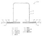
図1は、実施の形態1に係る臓器固定具の断面模式図である。
図1に示すように、臓器固定具100は、2本のロッド1a、1bと、ロッド1a及びロッド1bに連結された吊り上げ糸2と、ロッド1aの軸方向一端に連結された引き出し糸3aと、ロッド1bの軸方向一端に連結された引き出し糸3bとを備える。なお、ロッド1aとロッド1bは同様の構成であるので、これらをロッド1と総称して説明する場合がある。また、引き出し糸3aと引き出し糸3bも同様の構成であるので、これらを引き出し糸3と総称して説明する場合がある。また、ロッド1a、1bはそれぞれ本発明の第一ロッド、第二ロッドに相当し、引き出し糸3a、引き出し糸3bはそれぞれ本発明の第一引き出し糸、第二引き出し糸に相当する。[Organ fixation device]
1 is a schematic cross-sectional view of an organ fixing device according to
As shown in FIG. 1, the
ロッド1は、例えばステンレス鋼などの剛性を有する材料で構成された棒状の部材である。ロッド1の軸方向の略中央位置には吊り上げ糸2が連結され、ロッド1の軸方向の両端のうちの一方の端部(以下、引き出し端12と称する)には引き出し糸3が連結されている。ロッド1の両方の端部には面取りを施して丸みをつけている。このようにすることで、吊り上げ時に内臓壁等の生体組織が損傷されるのを抑制できるとともに、ロッド1を回収する際に内臓壁内からロッド1を抜き出しやすくなる。 The
吊り上げ糸2及び引き出し糸3は、生体内に挿通させたときに生体組織に沿って撓ることができる程度の柔軟性と、内臓を吊り上げ可能な程度の引っ張り強度とを有する材料(例えばナイロン糸)で構成されている。また、吊り上げ糸2と引き出し糸3は、詳細は後述するが臓器固定具100を患者に取り付けあるいは取り外す際に切断される。このため、吊り上げ糸2と引き出し糸3は、ハサミ等の医療現場に備えられている道具で切断可能な材料及び径寸法で構成するのが好ましい。 The lifting
本実施の形態1では、吊り上げ糸2と、ロッド1a、1bにそれぞれ接続された引き出し糸3a、3bは、1本の縫合糸4で構成されている。図1に示すように、本実施の形態1ではロッド1の内部は中空であり、ロッド1の両端は開放されている。また、ロッド1の軸方向中央部には、軸方向と直交する貫通孔11が設けられている。そして、貫通孔11と引き出し端12との間に、1本の縫合糸4が挿通されている。縫合糸4を貫通させた状態で、ロッド1の貫通孔11と引き出し端12との間の部分を押圧して凹ませて固定部13を形成することにより、縫合糸4をロッド1に固定している。なお、縫合糸4のロッド1への固定方法はこれに限定するものではなく、例えば、貫通孔11の外側と引き出し端12の外側において縫合糸4に結び目を作り、これにより縫合糸4をロッド1に固定するなど、任意の方法を用いることができる。また、本実施の形態1では、1本の縫合糸4により吊り上げ糸2と2本の引き出し糸3a、3bを構成する例を示したが、吊り上げ糸2と引き出し糸3a、3bを接続せず、個別に構成してもよい。 In the first embodiment, the lifting
[導入具]
次に、臓器固定具100を患者に導入するための導入具200について説明する。
図2は実施の形態1に係る導入具200の外観図、図3は導入具200の斜視図である。図2、図3に示すように、導入具200は、2本の穿刺針21a、21bと、穿刺針21aと21bとを保持する針保持部材31a、31bと、糸かけ部32と、押し出し部材33とを備えている。なお、穿刺針21aと穿刺針21bは同様の構成であるので、これらを穿刺針21と総称して説明する場合がある。[Introduction tool]
Next, an
2 is an external view of the
穿刺針21は、例えばステンレス鋼からなり、臓器固定具100のロッド1及び引き出し糸3を挿入可能な内腔を有している。穿刺針21の先端近傍には、穿刺針21を斜めにカットして生体の腹壁や臓器等を突き刺すことができるように尖らせた穿刺部22が形成されている。なお、図2、図3に示す例では、穿刺針21aの穿刺部22の刃面と穿刺針21bの穿刺部22の刃面とが同じ方向を向いているが、両刃面は向かい合っていてもよいし、また、両刃面はどの方向を向いていてもよい。また、穿刺部22の基端部分から穿刺針21の軸方向に沿って穿刺針21の周壁を切り欠いて、切欠部23を形成している。 The
針保持部材31は、2本の穿刺針21a、21bを、ほぼ平行に所定距離離間した状態で、かつ穿刺部22の先端位置がほぼ同じ位置となるように保持する。本実施の形態1では、2つの針保持部材31a、31bにより、針保持部材31を構成している。針保持部材31a、31bは、合成樹脂等の材料を直方体に成形して作られたものであり、それぞれに、穿刺針21a、21bが貫通している。すなわち、2つの針保持部材31a、31bと、2本の穿刺針21a、21bとが、井桁に組まれた状態である。針保持部材31aは穿刺針21a及び穿刺針21bの基端側を保持し、針保持部材31bは針保持部材31aよりも先端に近い部位で穿刺針21a及び穿刺針21bとを保持している。 The
針保持部材31aと針保持部材31bとの距離は、穿刺針21a、21bの揺動を抑制できる程度に設けておくのが好ましい。また、この針保持部材31a、31bは、術者が穿刺針21a、21bを患者に穿刺する際に把持する部分となる。このため、針保持部材31aの上端と針保持部材31bの下端とを、親指と他の四指とで把持することができるよう、針保持部材31aと針保持部材31bの配置を調整することで、術者による取り扱いを容易にすることができる。 It is preferable to provide the distance between the needle holding member 31a and the
なお、本実施の形態1では、2つの針保持部材31a、31bにより穿刺針21a、21bを保持する構成であるが、穿刺針21a、21bの軸方向先端部と基端部が揺動するのを抑制できるものであれば、任意の形状及び任意の数の部材で針保持部材を構成することができる。 In the first embodiment, the puncture needles 21a and 21b are held by the two
押し出し部材33は、2本の押し出し棒34a、34bと、この押し出し棒34a、34bの上部において両者を連結する連結部35とにより構成されている。なお、押し出し棒34a、34bは同様の構成であり、押し出し棒34と総称して説明する場合がある。
押し出し棒34は、穿刺針21の内腔に挿入されたロッド1を、穿刺針21の穿刺部22から放出させるための棒状部材である。押し出し棒34は、穿刺針21の内腔内を通過可能な外径を有する。穿刺針21の基端側から先端側に向かって押し出し棒34を押し込むことで、穿刺針21の内腔に挿入されたロッド1が穿刺針21の穿刺部22から放出される。押し出し棒34の材料は特に限定するものではないが、穿刺針21内のロッド1を突いて押し出すことのできる程度の硬さを有するような例えばステンレス鋼等の材料を用いることができる。The push-
The
連結部35は、押し出し棒34aと押し出し棒34bとをその上部で連結し、両者を一体に扱うことができるようにしている。連結部35は、術者が押し出し棒34を穿刺針21に押し込む際に押圧する操作部としても機能する。したがって、連結部35の外表面は術者が手で押圧しやすいようになめらかに形成しておくことが好ましい。また、押圧時に術者の指を受けることのできるような幅広の部位を連結部35に形成してもよく、このようにすることで術者の操作性を向上させることができる。なお、本実施の形態1では、1本の棒状部材をほぼ直角に折り曲げることにより、押し出し棒34a、連結部35、及び押し出し棒34bを一体に構成しているが、押し出し棒34a、34b、及び連結部35を別の部材で構成してこれらを溶接等により接続してもよい。また、連結部35の連結位置は、押し出し棒34a、34bの上部近傍であることが取り扱い上は好ましいが、必ずしも押し出し棒34a、34bの上端で連結しなくともよい。 The connecting
糸かけ部32は、導入具200に臓器固定具100を装着した際に、穿刺針21の先端から送り出された吊り上げ糸2を、穿刺針21の先端よりも基端側の位置で保持するためのものである。本実施の形態1では、針保持部材31の表面に、穿刺針21の軸方向と直交する方向に突出する直方体の糸かけ部32を設けている。糸かけ部32の形状は特に限定するものではないが、穿刺針21を立てて患者に突き刺す際に、吊り上げ糸2が下に落下しないよう保持できるものであればよく、例えばフック形状であってもよい。また、穿刺針21の先端から送り出された吊り上げ糸2を、弛まずに適度に張った状態で保持できる位置又は形状で、糸かけ部32を構成するのが好ましい。このようにすることで、臓器固定具100を装着した導入具200を取り扱う際に、意図せず吊り上げ糸2が糸かけ部32から落下するのを抑制できる。 The threading
[臓器固定具を導入具に装着した状態]
次に、導入具200に臓器固定具100を装着した状態について説明する。図4は導入具200に臓器固定具100を装着した状態を説明する図、図5は図4の要部拡大図、図6は、導入具200に臓器固定具100を装着した状態を説明する要部断面模式図である。なお、説明のため、図4では押し出し部材33を図示していない。[A state where the organ fixation device is attached to the introduction device]
Next, a state where the
図4〜図6に示すように、ロッド1a、1bは、それぞれ、その軸方向が穿刺針21の軸方向と一致するように縦向きで、穿刺針21a、21bの内腔に挿入される。また、ロッド1は、引き出し端12が穿刺針21の先端側に向く方向で、穿刺針21に挿入される。ロッド1a、1bの引き出し端12から延びる引き出し糸3a、3bは、引き出し端12の近傍で折り返され、それぞれ穿刺針21a、21bの内腔に軸方向基端側に向かって挿入されている。ロッド1a、1bに連結された吊り上げ糸2は、穿刺針21に設けられた切欠部23から穿刺針21の外側に引き出され、糸かけ部32に引っかけられている。 As shown in FIGS. 4 to 6, the
穿刺針21には切欠部23が設けられているので、吊り上げ糸2が連結された貫通孔11が切欠部23の基端部とほぼ一致する位置まで、ロッド1を穿刺針21内に押し込むことができる。このため、ロッド1が穿刺針21の刃面から出っ張ることなく、ロッド1を穿刺針21内に収めることができる。また、切欠部23を設けたので、切欠部23から吊り上げ糸2を引き出すことができ、穿刺針21の刃面で吊り上げ糸2が切断されるのを防ぐことができる。 Since the
なお、本実施の形態1では図6に示すように、ロッド1の引き出し端12が穿刺針21の先端側に向く方向でロッド1を穿刺針21に挿入する例を示すが、引き出し端12が穿刺針21の基端側に向く方向で、ロッド1を穿刺針21に挿入することもできる。 In the first embodiment, as shown in FIG. 6, an example in which the
ここで、臓器固定具100及び導入具200の各部の寸法について説明する。
臓器固定具100のロッド1は、例えば、外径が0.6mm、長さが10mm程度である。
臓器固定具100は、後述する図7(c)に示す状態で内蔵壁(胃壁)と腹壁とを固定する。このため、吊り上げ糸2は、内蔵壁の厚みと腹壁の厚みとを合わせた長さの2倍に、導入具200の穿刺針21a、21bの離間距離を加えた長さよりも短い長さとする。なお、内蔵壁の厚みと腹壁の厚みは患者により個人差があるので、患者の体型に合わせて複数種類の長さの吊り上げ糸2を品揃えするのが好ましい。また、引き出し糸3は、内蔵壁の厚みと、腹壁の厚みと、ロッド1の軸方向の長さの1/2と、指等でつまむことのできる長さとを足し合わせた長さとする。Here, the dimension of each part of the
For example, the
The
導入具200の穿刺針21の内径は、ロッド1及び引き出し糸3の外径よりも大きく、穿刺針21の長さは、例えば70mm〜150mm程度である。穿刺針21aと穿刺針21bとの離間距離は、ロッド1の軸方向の長さの1/2の2倍の長さ以上の長さとし、例えば、10mm〜15mm程度である。穿刺針21aと穿刺針21bとの離間距離が長すぎると、穿刺針21a、21bを患者に穿刺する際に術野を確保するのが困難になるとともに、内臓壁と腹壁とを固定する効果が弱まってしまう。逆に、穿刺針21aと穿刺針21bとの離間距離が、ロッド1の軸方向の長さの1/2の2倍の長さよりも短いと、後述する図7(c)に示すように臓器固定具100を患者に固定した場合に、ロッド1aとロッド1bとが重なってしまうおそれがある。 The inner diameter of the
穿刺針21の切欠部23の軸方向の長さは、臓器固定具100のロッド1の約1/2の長さである。また、切欠部23の幅は、吊り上げ糸2を通過させることができる程度の幅である。
押し出し棒34の長さは、穿刺針21の基端側から先端側に向かって押し出し棒34を押し込んだときに、穿刺針21内に挿入されたロッド1を穿刺針21の先端から放出することができる程度の長さが少なくとも必要である。The length in the axial direction of the
The length of the push-out
[内臓壁の固定手順]
次に、胃壁を腹壁に固定する際の臓器固定具100と導入具200の使用方法を説明する。図7は、実施の形態1に係る臓器固定具100と導入具200の使用方法を説明する図である。なお、図4〜図6で示したようにして、臓器固定具100が導入具200に装着された状態であるものとして説明する。[Internal wall fixing procedure]
Next, a method of using the
図7(a)に示すように、まず、臓器固定具100が装着された導入具200の穿刺針21a、21bを、腹壁41、胃壁42に穿刺し、穿刺部22を胃内43に到達させ、吊り上げ糸2を糸かけ部32から外す。穿刺針21を穿刺すると、穿刺針21の切欠部23から引き出された吊り上げ糸2も、穿刺針21と一緒に腹壁41と胃壁42を貫通して胃内43に進入する。穿刺針21に切欠部23を設け、切欠部23から引き出し糸2を引き出しているので、引き出し糸2が体表44に挿入される際の穿刺抵抗を低減できる。また、切欠部23から引き出し糸2を引き出しているので、穿刺針21の先端部22の刃面で引き出し糸2が切断されるのを防止できる。また、ロッド1が穿刺針21の先端部22よりも出っ張らないよう穿刺針21内に収められているので、穿刺針21で穿刺する際に、ロッド1が穿刺の妨げになることもない。 As shown in FIG. 7A, first, the puncture needles 21a and 21b of the
次に、図7(b)に示すように、穿刺針21a、21bの内腔に、押し出し棒34a、34bを挿入する。そして、押し出し部材33の連結部35を押圧することにより、穿刺針21a、21bの内腔に装入されたロッド1a、1bを、押し出し棒34a、34bの先端で押す。このようにすると、穿刺針21の穿刺部22からロッド1が繰り出される。穿刺針21から繰り出されたロッド1は、その略中央位置に吊り上げ糸2が連結されているので、吊り上げ糸2の吊り上げ方向に対してほぼ直交する方向に向きが変わる。 Next, as shown in FIG. 7B, push-out
次に、穿刺針21a、21bを、胃壁42及び腹壁41から抜去する。 Next, the puncture needles 21 a and 21 b are removed from the
穿刺針21a、21bを抜去すると、図7(c)に示すように、吊り上げ糸2とロッド1とが逆”T”字を形成する。また、穿刺時に穿刺針21内に挿入されていた引き出し糸3は、穿刺針21が抜去されるのに伴って穿刺針21から抜け、吊り上げ糸2に沿って腹壁41と胃壁42を貫通する。引き出し糸3の先端は、体表44側に出た状態となる。これで、2本のロッド1a、1bと吊り上げ糸2とにより、腹壁41と胃壁42とが2点で固定された状態となる。 When the puncture needles 21a and 21b are removed, the lifting
図6で示したように本実施の形態1では、ロッド1は、ロッド1の引き出し端12が穿刺針21の先端側に向く方向で穿刺針21に挿入されており、ロッド1の引き出し端12から延びる引き出し糸3は折り返されて穿刺針21内に挿入されている。このため、臓器固定具100が導入具200に装着されている間に、引き出し糸3がロッド1に沿うようにくせ付けされる。したがって、穿刺針21を抜去したときに、引き出し糸3が広がらず、引き出し糸3がロッド1にほぼ沿った状態でロッド1を胃内43に設置できる。 As shown in FIG. 6, in the first embodiment, the
また、体表44に出ている吊り上げ糸2を引っぱることで、胃壁42を腹壁41側に引き上げることができる。患者の腹壁41の厚みは個人差があるので、腹壁41の厚みに合わせて吊り上げ糸2を体表44側に引っ張り、適度に引っ張った状態で体表44側の吊り上げ糸2を結紮してもよい。なお、体表44側に出た引き出し糸3は、体表44に近い位置で短めに切っておくのが好ましい。このようにすることで、引き出し糸3が体表側から誤って引っ張られたり、引き出し糸3に物が引っかかったりするのを抑制できる。 Moreover, the
[臓器固定具の抜去手順]
臓器固定具100による固定が不要になった場合に、臓器固定具100を取り出す手順を説明する。図8は、実施の形態1に係る臓器固定具100の取り出し方法を説明する図である。[Procedure for removing organ fixator]
A procedure for taking out the
まず、図8(a)に示すように、体表44に露出している吊り上げ糸2を切断する。 First, as shown in FIG. 8A, the lifting
次に、体表44に露出している引き出し糸3を引っ張る。
引き出し糸3を引っ張ると、図8(b)に示すように、引き出し糸3が連結されたロッド1の引き出し端12が上に引っ張られ、ロッド1は徐々に垂直な向きとなる。さらに引き出し糸3を引っ張ると、ロッド1の引き出し端12が胃壁42、腹壁41を通って体表44側に引き出される。ロッド1の軸方向の端部には面取りを施して丸みをつけているので、胃壁42からロッド1を取り出すときに胃壁42が損傷されるのを抑制できるとともに、胃壁42内からロッド1を抜き出しやすくなる。Next, the
When the pull-
ロッド1が引き出されるのに伴い、ロッド1の略中央位置に連結された吊り上げ糸2もロッド1に沿って胃壁42、腹壁41を通って体表44側に引き出される。このように、体外から引き出し糸3を引っ張るだけで、胃内部のロッド1と吊り上げ糸2とを体外に取り出すことができる。 As the
以上のように、本実施の形態1の臓器固定具100は、一端がロッド1aの軸方向中央位置に接続され、他端がロッド1bの軸方向中央位置に接続されていて、ロッド1aとロッド1bとを連結する吊り上げ糸2を備えた。このように、吊り上げ糸2によりロッド1aとロッド1bとを連結したので、1回の手技で二点を固定することができる。したがって、従来よりも短時間で内臓壁と腹壁とを固定することができる。 As described above, the
また、ロッド1の軸方向一端である引き出し端12には、引き出し糸3を連結した。このため臓器固定具100が不要になった場合には、引き出し糸3を体外から引っ張るだけで臓器固定具100を体外に容易に取り出すことができ、術者の作業負担を軽減できる。また、不要になった臓器固定具100を速やかに取り出すことができるので、金属製のロッド1が体内に残留することもない。また、臓器固定具100を取り出すために内視鏡などの道具も不要であるので、患者への侵襲もわずかであり、患者の負担も軽減できる。 A pull-
また、ロッド1を中空部材で構成するとともに、1本の縫合糸4で吊り上げ糸2と2本の引き出し糸3a、3bを構成した。このため、部品点数を低減でき、臓器固定具100の製造コストを低減できる。 Further, the
また、実施の形態1に係る導入具200は、ロッド1a、1bを装着可能な2本の穿刺針21a、21bを備えた。このため、1回の手技で2本の穿刺針21a、21bを患者に穿刺し、2本のロッド1a、1bを臓器に導入できる。このため、従来よりも短時間で内臓壁と腹壁とを固定することができる。 In addition, the
また、実施の形態1に係る導入具200は、糸かけ部32を設けたので、穿刺針21を立てて患者に突き刺す際に、導入具200に装着された吊り上げ糸2が下方向に落下するのを防ぐことができる。また、糸かけ部32に吊り上げ糸2を引っかけておくことで、穿刺針21の内腔に装入されたロッド1が、穿刺針21の先端から下方向に落下するのを防ぐこともできる。 In addition, since the
また、実施の形態1に係る導入具200は、図7に示したように、穿刺針21による穿刺、押し出し部材33によるロッド1の繰り出し、穿刺針21の抜去、の3ステップで臓器固定具100を患者に導入することができる。このように、例えば特許文献1に記載の技術と比べて手技の手順が少なく簡単であるので、術者の作業負担を軽減できる。また、術者が臓器固定具100の導入に慣れるまでの時間を短縮することができる。 Further, as shown in FIG. 7, the
実施の形態2.
図9は、実施の形態2に係る臓器固定具100Aを説明する図である。実施の形態2に示す臓器固定具100Aは、吊り上げ糸2の長さ調節機構を備えた点に特徴を有する。本実施の形態2では、実施の形態1との相違点を中心に説明し、実施の形態1と同一又は対応する構成には同一の符号を付す。
FIG. 9 is a diagram illustrating an organ fixing device 100A according to the second embodiment. The organ fixing device 100A shown in the second embodiment is characterized in that a mechanism for adjusting the length of the lifting
図9に示すように、臓器固定具100Aは、カシメ材5を備えている。カシメ材5は、例えばアルミなどの比較的柔らかい金属で構成されており、吊り上げ糸2が貫通可能な筒部6a、6bを2本備えている。カシメ材5は、吊り上げ糸2がループ状になるようにして、吊り上げ糸2に摺動可能に取り付けられている。また、吊り上げ糸2は、実施の形態1で説明した長さよりも長めに構成されている。 As shown in FIG. 9, the
このように構成された臓器固定具100Aは、実施の形態1で説明したのと同様の手技で患者に導入される。図9(a)に示すように、患者に導入された臓器固定具100Aは、体表44側に吊り上げ糸2とカシメ材5が露出した状態となる。術者は、患者の腹壁41や胃壁42の厚みに合わせて、吊り上げ糸2を引っ張りつつカシメ材5の位置を調整する。そして、例えば鉗子等の器具を使ってカシメ材5の筒部6a、6bを圧迫することにより、カシメ材5が吊り上げ糸2に固定される。このようにすることで、図9(b)に示すように、胃壁42を腹壁41に固定することができる。すなわち、カシメ材5の位置を調整することで、ロッド1aとロッド1bとを結ぶ吊り上げ糸2の長さ、すなわち、胃壁42を腹壁41側に吊り上げる距離を調整することができるのである。 The organ fixing device 100A configured as described above is introduced into the patient by the same procedure as described in the first embodiment. As shown in FIG. 9A, the organ fixing device 100A introduced into the patient is in a state in which the
なお、カシメ材5を吊り上げ糸2に固定した後は、吊り上げ糸2のループ状の部分を短く切っておくことが好ましい。ループ状の吊り上げ糸2が体表44に露出していると、指や器具等がループ部分に引っかかってロッド1を体表側から引っ張ってしまうおそれがあるためである。 In addition, after fixing the crimping |
以上のように、本実施の形態2に係る臓器固定具100Aは、ロッド1aとロッド1bとを連結する吊り上げ糸2の長さを調節する長さ調節機構として、カシメ材5を設けた。このため、患者の腹壁や内臓壁の厚みに合った適切な状態で、内臓壁を腹壁に固定することができる。また、患者の腹壁や内臓壁の厚みに合わせた長さの吊り上げ糸2の品揃えも不要となり、製造コストが低減できる。また、術者も、患者の体型によらず同じ臓器固定具100Aを使用できるので、臓器固定具100Aの管理負担が軽減できる。 As described above, the organ fixing device 100A according to the second embodiment is provided with the
また、本実施の形態2の長さ調節機構であるカシメ材5は、アルミなどの柔らかい金属で構成した。このため、専用の道具を用いずとも、臓器固定を行う手術室などに備えられている鉗子などの道具を用いてカシメ材5を吊り上げ糸2に固定することができる。 Further, the
なお、吊り上げ糸2の長さ調節機構の具体的な構成は、本実施の形態2で示したカシメ材5に限定するものではない。例えば、アルミ等の比較的柔らかい金属製の円筒部材の中空部に吊り上げ糸2をループ状に通す構成としてもよい。そして、この円筒部材を外側から押圧して円筒部材により吊り上げ糸2を締め付けて円筒部材を吊り下げ糸2に固定することで、吊り上げ糸2の長さを調節してもよい。いずれにしても、臓器固定具を患者に取り付けた状態においてロッド1aからロッド1bに至る吊り上げ糸2の長さを調節できるものであればよい。 The specific configuration of the length adjusting mechanism of the lifting
実施の形態3.
図10は、導入具200に実施の形態3に係る臓器固定具100Bを装着した状態を説明する図である。また、図11は、実施の形態3に係る臓器固定具100Bを説明する図であり、患者に取り付けた状態を示している。本実施の形態3では、実施の形態1との相違点を中心に説明し、実施の形態1と同一又は対応する構成には同一の符号を付す。
FIG. 10 is a diagram illustrating a state in which the
図10、図11に示すように、臓器固定具100Bは、2つのコイルバネ7a、7b(コイルバネ7と総称する場合がある)を備えている。コイルバネ7a、7bには、吊り上げ糸2が挿通されている。すなわち、吊り上げ糸2の一部を囲うようにして、コイルバネ7a、7bが取り付けられている。なお、コイルバネ7a、7bは、本発明の弾性材に相当する。 As shown in FIGS. 10 and 11, the
このように構成された臓器固定具100Bは、実施の形態1で説明したのと同様の手技で患者に導入される。図11に示すように、患者に導入された臓器固定具100Bは、体表44に吊り上げ糸2とコイルバネ7a、7bとが露出した状態となり、コイルバネ7a、7bの下端が患者の体表44に当接する。すなわち、コイルバネ7とロッド1とで患者の胃壁42と体表44とを挟むこととなる。このため、コイルバネ7の反発力により、胃壁42と腹壁41とを固定する力が一定となる。 The
以上のように、本実施の形態3に係る臓器固定具100Bは、吊り上げ糸2が挿通された2個のコイルバネ7a、7bを備えた。このため、コイルバネ7a、7bの反発力により、内臓壁と腹壁とを固定する力が一定となる。例えば上記特許文献2に記載の従来技術の場合、内臓壁と腹壁とを固定する力の加減は術者に委ねられていた。このため、固定する力が強すぎる場合には鬱血して潰瘍ができるおそれがあり、固定する力が弱すぎる場合には十分に内臓壁を固定できないなど、術者の技量によって不都合が生じる可能性があった。しかし、本実施の形態3の臓器固定具100Bによれば、内臓壁と腹壁とを固定する力を一定にすることができるので、術者の技量や熟練度によらず、適切な力で固定することができる。 As described above, the
また、体表44とコイルバネ7aとの間、及び体表44とコイルバネ7bとの間に、例えばフェルトなどで構成された緩衝材を設けてもよい。このようにすることで、コイルバネ7a、7bの体表44への当たりを柔らかくすることができる。 Moreover, you may provide the buffer material comprised by the felt etc. between the body surface 44 and the
また、弾性材の具体的な構成は、本実施の形態3で示したコイルバネ7に限定するものではない。押圧されたときに復元力を発揮することのできる部材であればよく、例えば合成樹脂製の蛇腹状の管や、所定の厚みのゴム製部材を用いることもできる。 Further, the specific configuration of the elastic material is not limited to the
なお、上記実施の形態1〜3は、適宜組み合わせることができる。また、上記実施の形態1〜3では、2本の穿刺針を備えた導入具を示したが、導入具に3本あるいは4本の穿刺針を設けてもよい。 In addition, the said Embodiment 1-3 can be combined suitably. In the first to third embodiments, the introduction tool including two puncture needles is shown. However, three or four puncture needles may be provided in the introduction tool.
また、上記説明では胃壁を腹壁に固定する場合を例に説明したが、膀胱など他の臓器を腹壁に固定する場合にも、本発明の臓器固定具及び導入具を使用することができる。 In the above description, the case where the stomach wall is fixed to the abdominal wall has been described as an example, but the organ fixing device and the introduction device of the present invention can also be used when other organs such as the bladder are fixed to the abdominal wall.
1 ロッド、1a ロッド、1b ロッド、2 吊り上げ糸、3 引き出し糸、3a 引き出し糸、3b 引き出し糸、4 縫合糸、5 カシメ材、6a 筒部、6b 筒部、7a コイルバネ、7b コイルバネ、11 貫通孔、12 引き出し端、13 固定部、21 穿刺針、21a 穿刺針、21b 穿刺針、22 穿刺部、23 切欠部、31 針保持部材、31a 針保持部材、31b 針保持部材、32 糸かけ部、33 押し出し部材、34 押し出し棒、34a 押し出し棒、34b 押し出し棒、35 連結部、41 腹壁、42 胃壁、43 胃内、44 体表、100 臓器固定具、100A 臓器固定具、100B 臓器固定具、200 導入具。 1 rod, 1a rod, 1b rod, 2 lifting thread, 3 withdrawal thread, 3a withdrawal thread, 3b withdrawal thread, 4 suture thread, caulking material, 6a cylinder section, 6b cylinder section, 7a coil spring, 7b coil spring, 11 through hole , 12 Pull-out end, 13 Fixed part, 21 Puncture needle, 21a Puncture needle, 21b Puncture needle, 22 Puncture part, 23 Notch part, 31 Needle holding member, 31a Needle holding member, 31b Needle holding member, 32 Threading part, 33 Extruding member, 34 Extruding rod, 34a Extruding rod, 34b Extruding rod, 35 Connecting portion, 41 Abdominal wall, 42 Gastric wall, 43 Intragastric, 44 Body surface, 100 Organ fixing device, 100A Organ fixing device, 100B Organ fixing device, 200 Introduction Ingredients.
Claims (6)
Translated fromJapanese一端が前記第一ロッドの軸方向略中央位置に接続され、他端が前記第二ロッドの軸方向略中央位置に接続されていて、前記第一ロッドと第二ロッドとを連結する吊り上げ糸と、
前記第一ロッドの軸方向一端に連結された第一引き出し糸と、
前記第二ロッドの軸方向一端に連結された第二引き出し糸とを備えた臓器固定具の導入具であって、
内腔を有する2本の穿刺針と、
前記2本の穿刺針をほぼ平行に所定距離離間させて保持する針保持部材と、
前記2本の穿刺針の内腔を貫通自在な2本の押し出し棒の上部を連結して構成された押し出し部材とを備えた
ことを特徴とする臓器固定具の導入具。A first rod and a second rod;
One end is connected to a substantially central position in the axial direction of the first rod, the other end is connected to a substantially central position in the axial direction of the second rod, and a lifting thread that connects the first rod and the second rod; ,
A first draw thread connected to one axial end of the first rod;
Anorgan fixing tool introduction tool comprising a second lead thread connected to one axial end of the second rod,
Two puncture needles having a lumen;
A needle holding member that holds the two puncture needles at a predetermined distance apart in a substantially parallel manner;
And an extruding member configured by connecting upper portions of two extruding bars that can pass through the lumens of the two puncture needles.
An organ fixing tool introduction device characterized by the above.
前記臓器固定具の前記ロッドの中空部内で前記吊り上げ糸と前記2本の引き出し糸とを接続することにより、前記2本の引き出し糸と前記吊り上げ糸とが1本の糸部材で構成されている
ことを特徴とする請求項1記載の臓器固定具の導入具。The rodof the organ-fixing instrumentis constituted by a hollow member,
By connecting the lifting thread and the two withdrawal threads within the hollow portion of the rod of theorgan fixing device, the two withdrawal threads and the lifting threadare configuredby a single thread member. The organ fixing deviceintroducing device according to claim 1, wherein the organ fixing device isan introductory device .
ことを特徴とする請求項1〜請求項3のいずれか一項に記載の臓器固定具の導入具。The organ fixing device introducing device according to any one of claims 1 to 3, wherein the organ fixing device is an introducing device.
一端が前記第一ロッドの軸方向略中央位置に接続され、他端が前記第二ロッドの軸方向略中央位置に接続されていて、前記第一ロッドと第二ロッドとを連結する吊り上げ糸と、One end is connected to a substantially central position in the axial direction of the first rod, the other end is connected to a substantially central position in the axial direction of the second rod, and a lifting thread that connects the first rod and the second rod; ,
前記第一ロッドの軸方向一端に連結された第一引き出し糸と、A first draw thread connected to one axial end of the first rod;
前記第二ロッドの軸方向一端に連結された第二引き出し糸と、A second lead thread connected to one axial end of the second rod;
前記吊り上げ糸が挿通された2個の弾性材を備えたProvided with two elastic materials through which the lifting thread is inserted
ことを特徴とする臓器固定具。An organ fixing device characterized by that.
前記ロッドの中空部内で前記吊り上げ糸と前記2本の引き出し糸とを接続することにより、前記2本の引き出し糸と前記吊り上げ糸とを1本の糸部材で構成したBy connecting the lifting thread and the two withdrawal threads in the hollow portion of the rod, the two withdrawal threads and the lifting thread are configured by a single thread member.
ことを特徴とする請求項5記載の臓器固定具。The organ fixing tool according to claim 5.
Priority Applications (1)
| Application Number | Priority Date | Filing Date | Title |
|---|---|---|---|
| JP2010210530AJP5615112B2 (en) | 2010-09-21 | 2010-09-21 | Organ fixing device and organ fixing device |
Applications Claiming Priority (1)
| Application Number | Priority Date | Filing Date | Title |
|---|---|---|---|
| JP2010210530AJP5615112B2 (en) | 2010-09-21 | 2010-09-21 | Organ fixing device and organ fixing device |
Publications (2)
| Publication Number | Publication Date |
|---|---|
| JP2012065695A JP2012065695A (en) | 2012-04-05 |
| JP5615112B2true JP5615112B2 (en) | 2014-10-29 |
Family
ID=46163711
Family Applications (1)
| Application Number | Title | Priority Date | Filing Date |
|---|---|---|---|
| JP2010210530AExpired - Fee RelatedJP5615112B2 (en) | 2010-09-21 | 2010-09-21 | Organ fixing device and organ fixing device |
Country Status (1)
| Country | Link |
|---|---|
| JP (1) | JP5615112B2 (en) |
Cited By (4)
| Publication number | Priority date | Publication date | Assignee | Title |
|---|---|---|---|---|
| US9197173B2 (en) | 2007-01-31 | 2015-11-24 | Medtronic, Inc. | Chopper-stabilized instrumentation amplifier for impedance measurement |
| US9248288B2 (en) | 2007-09-26 | 2016-02-02 | Medtronic, Inc. | Patient directed therapy control |
| US9615744B2 (en) | 2007-01-31 | 2017-04-11 | Medtronic, Inc. | Chopper-stabilized instrumentation amplifier for impedance measurement |
| US9924904B2 (en) | 2014-09-02 | 2018-03-27 | Medtronic, Inc. | Power-efficient chopper amplifier |
Families Citing this family (1)
| Publication number | Priority date | Publication date | Assignee | Title |
|---|---|---|---|---|
| JP6284006B2 (en)* | 2014-01-31 | 2018-02-28 | 住友ベークライト株式会社 | Organ fixator |
Family Cites Families (7)
| Publication number | Priority date | Publication date | Assignee | Title |
|---|---|---|---|---|
| US5123914A (en)* | 1986-05-19 | 1992-06-23 | Cook Incorporated | Visceral anchor for visceral wall mobilization |
| JP3649459B2 (en)* | 1994-09-02 | 2005-05-18 | 住友ベークライト株式会社 | Internal organ lifting device |
| JP4619855B2 (en)* | 2005-04-27 | 2011-01-26 | 日本シャーウッド株式会社 | Organ fixture and organ fixture set |
| US7875041B2 (en)* | 2005-09-28 | 2011-01-25 | Olympus Medical Systems Corp. | Suturing method for penetrating hole |
| US9155532B2 (en)* | 2007-05-25 | 2015-10-13 | Cook Medical Technologies Llc | Medical devices, systems and methods for closing perforations |
| WO2010042402A1 (en)* | 2008-10-06 | 2010-04-15 | Wilson-Cook Medical, Inc. | Endcap for safely deploying tissue anchors |
| JP2012512715A (en)* | 2008-12-19 | 2012-06-07 | クック メディカル テクノロジーズ エルエルシー | A tacking device of varying thickness and method of delivery and deployment thereof |
- 2010
- 2010-09-21JPJP2010210530Apatent/JP5615112B2/ennot_activeExpired - Fee Related
Cited By (5)
| Publication number | Priority date | Publication date | Assignee | Title |
|---|---|---|---|---|
| US9197173B2 (en) | 2007-01-31 | 2015-11-24 | Medtronic, Inc. | Chopper-stabilized instrumentation amplifier for impedance measurement |
| US9615744B2 (en) | 2007-01-31 | 2017-04-11 | Medtronic, Inc. | Chopper-stabilized instrumentation amplifier for impedance measurement |
| US9248288B2 (en) | 2007-09-26 | 2016-02-02 | Medtronic, Inc. | Patient directed therapy control |
| US10258798B2 (en) | 2007-09-26 | 2019-04-16 | Medtronic, Inc. | Patient directed therapy control |
| US9924904B2 (en) | 2014-09-02 | 2018-03-27 | Medtronic, Inc. | Power-efficient chopper amplifier |
Also Published As
| Publication number | Publication date |
|---|---|
| JP2012065695A (en) | 2012-04-05 |
Similar Documents
| Publication | Publication Date | Title |
|---|---|---|
| EP2675364B1 (en) | Multiple loop device for passing suture tails through a surgical pledget | |
| US9924937B2 (en) | Knotless suture, and kit containing same | |
| US7674275B2 (en) | Suture anchor | |
| CN103037778B (en) | tissue retractor assembly | |
| JP4584230B2 (en) | Clip device | |
| EP2710964B1 (en) | Suture leader | |
| US8821520B2 (en) | Loader for knotting element | |
| EP2098172B1 (en) | System for meniscal repair using suture implant cinch construct | |
| JP4727295B2 (en) | Medical device and treatment system for living tissue | |
| JP6346659B2 (en) | Surgical suturing device with lateral engagement | |
| US20080027468A1 (en) | Suture needle, suture needle/suture assembly and suture passer device | |
| KR101326763B1 (en) | An apparatus for inserting a medical thread and a surgical procedure kit for inserting a medical thread comprising the same | |
| EP2796097A2 (en) | Devices, systems, and methods for suture management | |
| US20080269782A1 (en) | Surgical suturing apparatus | |
| US9301748B2 (en) | Suture apparatus, system and method | |
| CN110545736B (en) | Endovascular surgery system | |
| US10390818B2 (en) | Ferrule for use with a minimally invasive surgical suturing device | |
| KR20140022903A (en) | Advance suture passer | |
| JP5615112B2 (en) | Organ fixing device and organ fixing device | |
| US8734470B2 (en) | Surgical apparatus | |
| US10542969B2 (en) | Knotting device and methods of using the same | |
| CN105120768B (en) | stapler | |
| US8986379B2 (en) | Graft introducer | |
| JP4674114B2 (en) | Medical device and treatment system for living tissue | |
| EP2617367A1 (en) | Suture push-in device and suture push-in system |
Legal Events
| Date | Code | Title | Description |
|---|---|---|---|
| A621 | Written request for application examination | Free format text:JAPANESE INTERMEDIATE CODE: A621 Effective date:20130725 | |
| A977 | Report on retrieval | Free format text:JAPANESE INTERMEDIATE CODE: A971007 Effective date:20140115 | |
| A131 | Notification of reasons for refusal | Free format text:JAPANESE INTERMEDIATE CODE: A131 Effective date:20140218 | |
| A521 | Written amendment | Free format text:JAPANESE INTERMEDIATE CODE: A523 Effective date:20140411 | |
| TRDD | Decision of grant or rejection written | ||
| A01 | Written decision to grant a patent or to grant a registration (utility model) | Free format text:JAPANESE INTERMEDIATE CODE: A01 Effective date:20140826 | |
| A61 | First payment of annual fees (during grant procedure) | Free format text:JAPANESE INTERMEDIATE CODE: A61 Effective date:20140909 | |
| R150 | Certificate of patent or registration of utility model | Ref document number:5615112 Country of ref document:JP Free format text:JAPANESE INTERMEDIATE CODE: R150 | |
| S531 | Written request for registration of change of domicile | Free format text:JAPANESE INTERMEDIATE CODE: R313531 | |
| R350 | Written notification of registration of transfer | Free format text:JAPANESE INTERMEDIATE CODE: R350 | |
| LAPS | Cancellation because of no payment of annual fees |