JP5614935B2 - Vaporizer, vaporizer for MOCVD using this vaporizer, center rod used in these vaporizers or vaporizer for MOCVD, and carrier gas distribution - Google Patents
Vaporizer, vaporizer for MOCVD using this vaporizer, center rod used in these vaporizers or vaporizer for MOCVD, and carrier gas distributionDownload PDFInfo
- Publication number
- JP5614935B2 JP5614935B2JP2009023063AJP2009023063AJP5614935B2JP 5614935 B2JP5614935 B2JP 5614935B2JP 2009023063 AJP2009023063 AJP 2009023063AJP 2009023063 AJP2009023063 AJP 2009023063AJP 5614935 B2JP5614935 B2JP 5614935B2
- Authority
- JP
- Japan
- Prior art keywords
- carrier gas
- center rod
- vaporizer
- thin film
- cooling
- Prior art date
- Legal status (The legal status is an assumption and is not a legal conclusion. Google has not performed a legal analysis and makes no representation as to the accuracy of the status listed.)
- Expired - Fee Related
Links
- 239000012159carrier gasSubstances0.000titleclaimsdescription104
- 239000006200vaporizerSubstances0.000titleclaimsdescription58
- 238000002488metal-organic chemical vapour depositionMethods0.000titleclaimsdescription21
- 238000009826distributionMethods0.000titledescription4
- 239000007789gasSubstances0.000claimsdescription117
- 238000001816coolingMethods0.000claimsdescription98
- 239000000463materialSubstances0.000claimsdescription66
- 239000010409thin filmSubstances0.000claimsdescription64
- 239000006185dispersionSubstances0.000claimsdescription24
- XLYOFNOQVPJJNP-UHFFFAOYSA-NwaterSubstancesOXLYOFNOQVPJJNP-UHFFFAOYSA-N0.000claimsdescription18
- 230000008016vaporizationEffects0.000claimsdescription17
- 238000003780insertionMethods0.000claimsdescription15
- 230000037431insertionEffects0.000claimsdescription15
- 238000000034methodMethods0.000claimsdescription14
- 239000000498cooling waterSubstances0.000claimsdescription11
- 238000009834vaporizationMethods0.000claimsdescription11
- 230000005855radiationEffects0.000claimsdescription9
- 230000002265preventionEffects0.000claimsdescription6
- 230000002093peripheral effectEffects0.000claimsdescription4
- 238000005304joiningMethods0.000claimsdescription2
- 239000002994raw materialSubstances0.000description27
- 238000002347injectionMethods0.000description23
- 239000007924injectionSubstances0.000description23
- 239000000243solutionSubstances0.000description21
- 239000007788liquidSubstances0.000description14
- 238000006243chemical reactionMethods0.000description13
- WYURNTSHIVDZCO-UHFFFAOYSA-NTetrahydrofuranChemical compoundC1CCOC1WYURNTSHIVDZCO-UHFFFAOYSA-N0.000description11
- QVGXLLKOCUKJST-UHFFFAOYSA-Natomic oxygenChemical compound[O]QVGXLLKOCUKJST-UHFFFAOYSA-N0.000description9
- 239000001301oxygenSubstances0.000description9
- 229910052760oxygenInorganic materials0.000description9
- 230000000694effectsEffects0.000description8
- 239000002904solventSubstances0.000description8
- 238000003860storageMethods0.000description8
- 238000011144upstream manufacturingMethods0.000description8
- 230000015572biosynthetic processEffects0.000description5
- YLQBMQCUIZJEEH-UHFFFAOYSA-NtetrahydrofuranNatural productsC=1C=COC=1YLQBMQCUIZJEEH-UHFFFAOYSA-N0.000description5
- 239000010408filmSubstances0.000description4
- 238000012423maintenanceMethods0.000description4
- 125000002524organometallic groupChemical class0.000description4
- 238000005229chemical vapour depositionMethods0.000description3
- 239000003595mistSubstances0.000description3
- 239000000843powderSubstances0.000description3
- 238000010926purgeMethods0.000description3
- 238000007789sealingMethods0.000description3
- 239000007787solidSubstances0.000description3
- 238000010521absorption reactionMethods0.000description2
- 238000010586diagramMethods0.000description2
- 230000006870functionEffects0.000description2
- 238000010438heat treatmentMethods0.000description2
- 239000012535impuritySubstances0.000description2
- 238000012986modificationMethods0.000description2
- 230000004048modificationEffects0.000description2
- 238000012545processingMethods0.000description2
- 238000000427thin-film depositionMethods0.000description2
- 229920006362Teflon®Polymers0.000description1
- 238000013459approachMethods0.000description1
- 238000009835boilingMethods0.000description1
- 239000003990capacitorSubstances0.000description1
- 239000000919ceramicSubstances0.000description1
- 238000004140cleaningMethods0.000description1
- 238000004891communicationMethods0.000description1
- 150000001875compoundsChemical class0.000description1
- 238000011109contaminationMethods0.000description1
- 239000003989dielectric materialSubstances0.000description1
- 238000005516engineering processMethods0.000description1
- 238000001704evaporationMethods0.000description1
- 230000008020evaporationEffects0.000description1
- 150000004820halidesChemical class0.000description1
- 230000017525heat dissipationEffects0.000description1
- 238000004519manufacturing processMethods0.000description1
- 230000008018meltingEffects0.000description1
- 238000002844meltingMethods0.000description1
- 239000012528membraneSubstances0.000description1
- 150000001247metal acetylidesChemical class0.000description1
- 239000007800oxidant agentSubstances0.000description1
- 230000001590oxidative effectEffects0.000description1
- 238000005240physical vapour depositionMethods0.000description1
- 230000002035prolonged effectEffects0.000description1
- 239000004065semiconductorSubstances0.000description1
- 238000003980solgel methodMethods0.000description1
- 238000000638solvent extractionMethods0.000description1
- 229910001220stainless steelInorganic materials0.000description1
- 239000010935stainless steelSubstances0.000description1
- 230000003068static effectEffects0.000description1
- 239000000126substanceSubstances0.000description1
- 238000012546transferMethods0.000description1
Images


Classifications
- C—CHEMISTRY; METALLURGY
- C23—COATING METALLIC MATERIAL; COATING MATERIAL WITH METALLIC MATERIAL; CHEMICAL SURFACE TREATMENT; DIFFUSION TREATMENT OF METALLIC MATERIAL; COATING BY VACUUM EVAPORATION, BY SPUTTERING, BY ION IMPLANTATION OR BY CHEMICAL VAPOUR DEPOSITION, IN GENERAL; INHIBITING CORROSION OF METALLIC MATERIAL OR INCRUSTATION IN GENERAL
- C23C—COATING METALLIC MATERIAL; COATING MATERIAL WITH METALLIC MATERIAL; SURFACE TREATMENT OF METALLIC MATERIAL BY DIFFUSION INTO THE SURFACE, BY CHEMICAL CONVERSION OR SUBSTITUTION; COATING BY VACUUM EVAPORATION, BY SPUTTERING, BY ION IMPLANTATION OR BY CHEMICAL VAPOUR DEPOSITION, IN GENERAL
- C23C16/00—Chemical coating by decomposition of gaseous compounds, without leaving reaction products of surface material in the coating, i.e. chemical vapour deposition [CVD] processes
- C23C16/44—Chemical coating by decomposition of gaseous compounds, without leaving reaction products of surface material in the coating, i.e. chemical vapour deposition [CVD] processes characterised by the method of coating
- C23C16/448—Chemical coating by decomposition of gaseous compounds, without leaving reaction products of surface material in the coating, i.e. chemical vapour deposition [CVD] processes characterised by the method of coating characterised by the method used for generating reactive gas streams, e.g. by evaporation or sublimation of precursor materials
- C23C16/4481—Chemical coating by decomposition of gaseous compounds, without leaving reaction products of surface material in the coating, i.e. chemical vapour deposition [CVD] processes characterised by the method of coating characterised by the method used for generating reactive gas streams, e.g. by evaporation or sublimation of precursor materials by evaporation using carrier gas in contact with the source material
- B—PERFORMING OPERATIONS; TRANSPORTING
- B01—PHYSICAL OR CHEMICAL PROCESSES OR APPARATUS IN GENERAL
- B01B—BOILING; BOILING APPARATUS ; EVAPORATION; EVAPORATION APPARATUS
- B01B1/00—Boiling; Boiling apparatus for physical or chemical purposes ; Evaporation in general
- B01B1/005—Evaporation for physical or chemical purposes; Evaporation apparatus therefor, e.g. evaporation of liquids for gas phase reactions
- H—ELECTRICITY
- H01—ELECTRIC ELEMENTS
- H01L—SEMICONDUCTOR DEVICES NOT COVERED BY CLASS H10
- H01L21/00—Processes or apparatus adapted for the manufacture or treatment of semiconductor or solid state devices or of parts thereof
- H01L21/02—Manufacture or treatment of semiconductor devices or of parts thereof
- H01L21/02104—Forming layers
- H01L21/02365—Forming inorganic semiconducting materials on a substrate
- H01L21/02612—Formation types
- H01L21/02617—Deposition types
- H01L21/0262—Reduction or decomposition of gaseous compounds, e.g. CVD
- H—ELECTRICITY
- H01—ELECTRIC ELEMENTS
- H01L—SEMICONDUCTOR DEVICES NOT COVERED BY CLASS H10
- H01L21/00—Processes or apparatus adapted for the manufacture or treatment of semiconductor or solid state devices or of parts thereof
- H01L21/02—Manufacture or treatment of semiconductor devices or of parts thereof
- H01L21/04—Manufacture or treatment of semiconductor devices or of parts thereof the devices having potential barriers, e.g. a PN junction, depletion layer or carrier concentration layer
- H01L21/18—Manufacture or treatment of semiconductor devices or of parts thereof the devices having potential barriers, e.g. a PN junction, depletion layer or carrier concentration layer the devices having semiconductor bodies comprising elements of Group IV of the Periodic Table or AIIIBV compounds with or without impurities, e.g. doping materials
- H01L21/30—Treatment of semiconductor bodies using processes or apparatus not provided for in groups H01L21/20 - H01L21/26
- H01L21/31—Treatment of semiconductor bodies using processes or apparatus not provided for in groups H01L21/20 - H01L21/26 to form insulating layers thereon, e.g. for masking or by using photolithographic techniques; After treatment of these layers; Selection of materials for these layers
Landscapes
- Chemical & Material Sciences (AREA)
- Engineering & Computer Science (AREA)
- Chemical Kinetics & Catalysis (AREA)
- General Chemical & Material Sciences (AREA)
- Materials Engineering (AREA)
- Mechanical Engineering (AREA)
- Metallurgy (AREA)
- Organic Chemistry (AREA)
- Physics & Mathematics (AREA)
- Condensed Matter Physics & Semiconductors (AREA)
- General Physics & Mathematics (AREA)
- Manufacturing & Machinery (AREA)
- Computer Hardware Design (AREA)
- Microelectronics & Electronic Packaging (AREA)
- Power Engineering (AREA)
- Chemical Vapour Deposition (AREA)
Description
Translated fromJapanese本発明は、キャリアガスを用いて複数の薄膜形成材料からなる原料溶液等を気化するための気化器、この気化器を用いたMOCVD用気化器、これら気化器若しくはMOCVD用気化器に用いられるセンターロッド、及びキャリアガスの分散方法並びにキャリアガスの気化方法に関する。 The present invention relates to a vaporizer for vaporizing a raw material solution composed of a plurality of thin film forming materials using a carrier gas, a vaporizer for MOCVD using this vaporizer, a center used for these vaporizers or a vaporizer for MOCVD. The present invention relates to a rod, a carrier gas dispersion method, and a carrier gas vaporization method.
近年、電子デバイスの分野においては、回路の高密度化と共に電子デバイスの一層の小型化および高性能化が望まれており、例えば、トランジスタの組み合わせで情報の記憶動作を行うSRAM(Static Random Access read write Memory)、EEPROM(Electrically Erasable and Programmable Read Only Memory)、或いはトランジスタとキャパシタの組み合わせで情報の記憶動作を行うDRAM(Dynamic Random Access Memory)等のように、電子デバイスの機能を単に回路構成のみで達成するばかりではなく、機能性薄膜等の材料自体の特性を利用してデバイスの機能を実現することが有利になりつつある。 In recent years, in the field of electronic devices, there has been a demand for further miniaturization and higher performance of electronic devices along with higher circuit density. For example, an SRAM (Static Random Access read) that stores information by combining transistors. A circuit such as a write memory (EEPROM), an EEPROM (Electrically Erasable and Programmable Read Only Memory), or a DRAM (Dynamic Random Access Memory) that performs a storage operation of information with a combination of a transistor and a capacitor, and the like. In addition to achieving this, it is becoming more advantageous to realize device functions by utilizing the characteristics of materials such as functional thin films themselves. .
また、このような半導体にあっては、例えば、クレジットカード等のICチップとして搭載され、その技術はパスポート用個人情報記憶チップ等へと多様化しつつある。 In addition, such a semiconductor is mounted as an IC chip such as a credit card, for example, and the technology is diversifying into a personal information storage chip for a passport or the like.
そのため、電子部品に用いられる誘電体材料等の薄膜化が望まれている。このような材料を薄膜化する一つの方法として、CVD法がある。 Therefore, it is desired to reduce the thickness of dielectric materials used for electronic parts. One method for thinning such a material is a CVD method.
このCVD法は、PVD法、ゾルゲル法、その他の成膜法に比べて成膜速度が大きく、多層薄膜の製造が容易であるなどの特徴を有している。また、MOCVD法は、有機物を含む化合物を薄膜形成用の原料として用いるCVD法であり、安全性が高く、膜中のハロゲン化物の混入がないなどの利点を有する。 This CVD method has features such as a higher film formation speed and easier production of multilayer thin films than the PVD method, sol-gel method, and other film formation methods. The MOCVD method is a CVD method using a compound containing an organic substance as a raw material for forming a thin film, and has advantages such as high safety and no inclusion of halide in the film.
MOCVD法に用いられる原料は、一般的に固体粉末あるいは液体であり、これらの原料を容器に入れ、一般的に減圧中で加熱して原料を気化器で気化させた後、キャリアガスによって薄膜成膜装置内に送り込んでいる。 The raw materials used in the MOCVD method are generally solid powders or liquids. These raw materials are put in a container, generally heated in a reduced pressure to vaporize the raw materials in a vaporizer, and then a thin film is formed with a carrier gas. It is fed into the membrane device.
図7は、このようなMOCVD法の気化システムのシステムブロック図(特許文献1参照)である。 FIG. 7 is a system block diagram of such a MOCVD vaporization system (see Patent Document 1).
図7において、10は複数の原料溶液等を気化器1へと供給する供給部である。 In FIG. 7,
供給部10は、キャリアガス(例えば、N2又はAr)が充填されたガスボンベ11と、酸素が充填された酸素ボンベ12と、冷却水が貯留された貯水タンク13と、強誘電体薄膜用の原料(例えば、3種類の有機金属錯体としてSr(DPM)2、Bi(C6H5)3、Ta(OC2H5)5)並びに溶剤としてTHF(テトラヒドロフラン)を貯留した複数のリザーブタンク14〜17と、ガスボンベ11と気化器1とに接続されたガス供給管18と、酸素ボンベ12と気化器1とに接続された酸素供給管19と、貯水タンク13と気化器1とに接続された給水管20並びに配水管21と、リザーブタンク14〜17と気化器1とに接続された液体供給管22〜25と、リザーブタンク14〜17とガスボンベ11とに接続された多岐管26とを備えている。 The
ガス供給管18の経路中にはバルブ18aとマスフローコントローラ18bとが設けられ、酸素供給管19の経路中にはバルブ19aとマスフローコントローラ19bとバルブ19cとが設けられ、給水管20の経路中にはバルブ20aが設けられている。また、溶剤用の液体供給管22の経路中にはバルブ22aとマスフローコントローラ22bとが設けられ、錯体用の液体供給管23〜25の経路中にはバルブ23a〜25aとマスフローコントローラ23a〜25bとが設けられ、多岐管26の経路中にはバルブ26a〜26dとエアパージ26eとバルブ26fとが設けられている。尚、液体供給管23〜25は、液体供給管22と接続されるように分岐されており、それぞれバルブ23c〜25cが設けられている。 A
ガスボンベ11に充填されたキャリアガスは、ガス供給管18のバルブ18aを開くことにより、マスフローコントローラ18bに流量制御されて気化器1へと供給される。また、ガスボンベ11に充填されたキャリアガスは、多岐管26のバルブ26f並びにバルブ26a〜26dを開くと共にエアパージ用のバルブ26eの放出状態を閉とすることによりキャリアガスがリザーブタンク14〜17に送り込まれる。これにより、リザーブタンク14〜17内はキャリアガスにより加圧され、貯留された原料溶液はその溶液内に先端が臨んでいる液体供給管22〜25内を押し上げられてマスフローコントロ―ラ22b〜25bにより流量制御された後、気化器1に輸送される。 The carrier gas filled in the
また、同時に、酸素ボンベ12からマスフロ―コントロ―ラ19bで―定流量に制御された酸素(酸化剤)が気化器1へと輸送される。 At the same time, oxygen (oxidant) controlled to a constant flow rate is transported from the
さらに、給水管20のバルブ20aを開くことにより貯水タンク13内の冷却水が気化器1の内部を循環して気化器1を冷却する。 Further, by opening the
尚、薄膜形成材料供給部27〜30は、図示例では気化器1の軸線方向に沿って並設されているが、実際には貯水タンク13からの給水管20又は配水管21と接続される接続部31,32とで放射状に交互に設けられている。 The thin film forming
リザーブタンク15〜17内に貯留された原料溶液は、溶剤であるTHFに常温で液体又は固体状の有機金属錯体(Sr(DPM)2、Bi(C6H5)3、Ta(OC2H5)5)を溶解しているため、そのまま放置しておくとTHF溶剤の蒸発によって有機金属錯体が析出し、最終的に固形状になる。 The raw material solution stored in the
従って、原液と接触した液体供給管23〜25の内部がこれによって閉塞されることを防止するため、成膜作業終了後の液体供給管23〜25内及び気化器1内をリザーブタンク14内のTHFで洗浄すればよい。この際の洗浄は、マスフロ―コントローラ13b〜25bの出口側から気化器1までの区間とし、作業終了後にリザーブタンク14内に貯留されたTHFで洗い流すものである。 Therefore, in order to prevent the inside of the
図5は、気化器1の一例の要部の構成を示す断面図である(特許文献1参照)。 FIG. 5 is a cross-sectional view showing a configuration of a main part of an example of the vaporizer 1 (see Patent Document 1).
図5に示した気化器1は、気化器1は、ガス供給管18が接続される分散器(分散部本体)2と、分散器2の下流側に連続して接続された反応管3と、反応管3の周囲を覆うヒータ4とを備えている。 The
分散器2は、ガス供給管18と同軸上に位置するガス通路5を有する。このガス通路5の始端上流口5aと終端噴射口5bとの間には、各薄膜形成材料供給部27〜30の先端が臨んでおり(図では対向配置された薄膜形成材料供給部28,29のみ図示)、これによりリザーブタンク15〜17内に貯留された原料溶液がこのガス通路5内に供給可能となっている。また、分散器2には、接続部31,32に連通して貯水タンク13内の冷却水が循環するための冷却経路6が形成されている。さらに、分散器2には、ガス供給管18の始端上流口5aよりも上流側に一端が位置すると共に終端噴射口5bに他端が位置するセンターロッド7と、このセンターロッド7の先端側(ガス通路5の下流側)を支持するピン8と、を備えている。尚、センターロッド7の基端側(ガス通路5の上流側)はガス供給管18の端部付近に設けられたピン9により保持されている。 The
このような構成においては、分散器2の内部にキャリアガス導入穴を貫通し、そのキャリアガス導入穴の軸線と同軸上に位置するように、キャリアガス導入穴の内径(4.50mm)のよりも小さな外径(4.48mm)を有するセンターロッド7を配置する。 In such a configuration, the inner diameter (4.50 mm) of the carrier gas introduction hole is arranged so as to penetrate the carrier gas introduction hole inside the
また、この分散器2のキャリアガス導入穴の内壁とセンターロッド7との間の協働によってガス通路5が形成される。 The
尚、ガス通路5の断面幅は0.02mmとなる。この際、ガス通路5の断面幅は、0.005〜0.10mmが好ましい。これは、0.005mm未満では加工が困難であり、0.10mmを超えるとキャリアガスを高速化するために高圧のキャリアガスを用いる必要が生じてしまうからである。 The cross-sectional width of the
ガス通路5の上流からは、ガス供給管18からキャリアガスが導入される。このキャリアガスには、ガス通路5の中途部に位置する各薄膜形成材料供給部27〜30の先端から原料溶液が滴下されるため、この原料溶液がガス通路5を通過するキャリアガスに分散されてミスト状となる。 A carrier gas is introduced from the
これにより、ガス通路5の下流の終端噴射口5bから反応管3に原料溶液を分散したキャリアガスが噴射され、反応管3内を流れる原料溶液を分散したキャリアガスをヒータ4で加熱し気化した後、図示を略する薄膜成膜装置へと送り込まれる。 As a result, the carrier gas in which the raw material solution is dispersed is injected from the
ところで、気化器1に配置される冷却部としては、上述したように、ガス通路5の略全長に跨る冷却経路6を形成する他、例えば、図6に示すように、センターロッド7の中途部から先端側に位置するガス通路5内を冷却する冷却システム33を配置したものも知られている(例えば、特許文献2参照)。 By the way, as a cooling part arrange | positioned at the vaporizer |
尚、図6において、上記図5に示した気化器1と同様の機能には、同一の符号を付してその説明を省略する。 In FIG. 6, functions similar to those of the
ところで、上記の如く構成された気化器1にあっては、気化器1の終端噴射口5bの周囲に薄膜原料が付着してしまうという現象が生じていた。 By the way, in the
即ち、ガス通路5を通過するキャリアガス(特に、原料溶液が分散された後のキャリアガス)は、ガス通路5の内部が高温環境化にあるため、終端噴射口5bに至る前にミスト状の原料溶液の水分が蒸発してしまうと、その材料粉末成分等が終端噴射口5bの周囲に付着してしまう。また、このような材料粉末成分等は経時的に成長して終端噴射口5bの目詰りの原因となってしまうばかりでなく、不純物の混入といった問題にも発展してしまう虞が生じていた。 That is, the carrier gas that passes through the gas passage 5 (particularly the carrier gas after the raw material solution is dispersed) is in a mist state before reaching the
そこで、このようなガス通路5内の高温環境化に対応するため、ガス通路5よりも外周に冷却経路6を形成し、この冷却経路6に冷却水を循環させることでガス通路5を冷却している。 Therefore, in order to cope with such a high temperature environment in the
しかしながら、冷却経路6は分散器2に形成されていることから、ガス通路5の外側から伝熱効果を利用して間接的にガス通路5を冷却するため、ガス通路5と冷却経路6とを区画する分散器2の肉厚分だけ熱損失が発生する等、冷却効果が薄いという問題が生じていた。 However, since the
本発明は、上記問題を解決するため、キャリアガスを効率良く冷却することができ、ガス通路出口付近での材料目詰り発生防止効果を向上し得て、メンテナンス時期の長期化並びに稼動効率の向上に貢献することができ、しかも、より一層均一な分散効果を奏することができる気化器を提供することを目的とする。 In order to solve the above problems, the present invention can efficiently cool the carrier gas, can improve the material clogging prevention effect in the vicinity of the gas passage outlet, prolong the maintenance time, and improve the operation efficiency. Another object of the present invention is to provide a vaporizer capable of contributing to the above-mentioned and having a more uniform dispersion effect.
その目的を達成するため、参考発明の気化器は、分散部本体に形成されたキャリアガス導入穴に挿入されて該キャリアガス導入穴の内壁との協働によりガス通路を形成するセンターロッドと、前記分散部本体の前記キャリアガス導入穴の外周側に配置されて前記ガス通路内を冷却する冷却部と、前記センターロッドの軸線方向に沿い且つ前記センターロッドの略全長に跨って形成された冷却部材挿入穴と、該冷却部材挿入穴内に配置されて前記センターロッドを冷却する冷却部材と、を備えていることを特徴とする。In order to achieve the object,the vaporizer of thereference invention includes a center rod that is inserted into a carrier gas introduction hole formed in the dispersion portion body and forms a gas passage through cooperation with the inner wall of the carrier gas introduction hole; A cooling part that is disposed on the outer peripheral side of the carrier gas introduction hole of the dispersion part main body and cools the inside of the gas passage, and cooling that is formed along the axial direction of the center rod and over substantially the entire length of the center rod A member insertion hole and a cooling member disposed in the cooling member insertion hole to cool the center rod are provided.
上記の気化器によれば、冷却部と冷却部材とによってキャリアガスを効率良く冷却することができる。According tothe vaporizer, she is possible to efficiently cool the carrier gas by the cooling unit and the cooling member.
請求項1に記載の気化器は、分散部本体に形成されたキャリアガス導入穴の全長に跨って挿入されて該キャリアガス導入穴の内壁との協働によりガス通路を形成するセンターロッドと、前記分散部本体の複数個所に形成されて前記ガス通路の中途部に複数の薄膜形成材料を供給する薄膜形成材料供給部と、前記分散部本体の前記キャリアガス導入穴の外周側に配置されて前記ガス通路内を冷却する冷却部と、前記センターロッドの軸線方向に沿い且つ前記センターロッドの略全長に跨って形成された冷却部材挿入穴と、該冷却部材挿入穴内に配置されて前記センターロッドを冷却する冷却部材と、を備え、
前記冷却部と前記冷却部材は、少なくとも薄膜形成材料供給部から前記ガス通路の下流端付近に跨って配置されていることを特徴とする。The vaporizer according to
The cooling unit and the cooling member are arranged to straddle at least thevicinity of the downstream end of the gas passage from the thin film forming material supply unit.
請求項1に記載の気化器によれば、薄膜形成材料供給部から供給された薄膜形成材料を分散させたキャリアガスを含めてキャリアガスを効率良く冷却することができる。According to the vaporizer of thefirst aspect , the carrier gas can be efficiently cooled including the carrier gas in which the thin film forming material supplied from the thin film forming material supply unit is dispersed.
請求項3に記載のMOCVD用気化器は、上記の気化器に隣接して前記分散部本体で複数の薄膜形成材料を分散させたキャリアガスを気化する気化部を設けたことを特徴とする。MOCVD vaporizer according to
請求項3に記載のMOCVD用気化器によれば、冷却部と冷却部材とによって効率良く冷却されたキャリアガスの材料目詰り発生防止効果を向上し得て、メンテナンス時期の長期化並びに稼動効率の向上に貢献することができ、しかも、より一層均一な分散効果を奏することができる。According to the vaporizer for MOCVD according to
請求項4に記載のセンターロッドは、上記の気化器若しくはMOCVD用気化器に使用されるセンターロッドであって、前記センターロッドの外周に形成され且つ適用する薄膜形成材料と1対1で対応した複数のガイド溝を備えていることを特徴とする。Center rod according to
請求項5に記載のセンターロッドは、前記冷却部材が、略円筒形状のペルチェ素子であることを特徴とする。The center rod according to
請求項6に記載のセンターロッドは、前記冷却部材が、前記冷却部材挿入穴に吸熱部を配置したヒートパイプであることを特徴とする。The center rod described in
請求項7に記載のセンターロッドは、前記冷却部材が、ポンプを介して冷却水が給排水される螺旋状又は略U字状の冷水パイプであることを特徴とする。The center rod described in
請求項8に記載のセンターロッドは、前記冷却部材は、前記センターロッドに着脱可能に挿入されていることを特徴とする。The center rod described in
請求項9に記載のキャリアガスの冷却分散方法は、分散部本体に形成されたキャリアガス導入穴の内壁と該キャリアガス導入穴に挿入されたセンターロッドとの間に形成されたガス通路に複数の薄膜形成材料を分散させたキャリアガスを導入すると共に、該薄膜形成材料を分散させたキャリアガスを前記分散部本体に配置した冷却部と前記センターロッドに配置した冷却部材とで少なくとも薄膜形成材料供給部から前記ガス通路の下流端付近に跨って冷却しつつ前記ガス通路内を搬送することを特徴とする。The method for cooling and dispersing the carrier gas according to
請求項9に記載のキャリアガスの冷却分散方法によれば、冷却部と冷却部材とによって効率良く冷却されたキャリアガスを導入することができる。According to the carrier gas cooling and dispersing method of theninth aspect , the carrier gas cooled efficiently by the cooling unit and the cooling member can be introduced.
さらに、請求項10に記載のキャリアガスの気化方法は、分散部本体に形成されたキャリアガス導入穴の内壁と該キャリアガス導入穴に挿入されたセンターロッドとの間に形成されたガス通路にキャリアガスを導入すると共に、前記ガス通路の中途部複数箇所から薄膜形成材料を導入してキャリアガスに前記薄膜形成材料を分散させた後に、前記ガス通路の下流端部に配置されたセンターロッド先端によって互いに接近する方向に案内される合流部にて前記薄膜形成材料を分散させたキャリアガスを合流させた後に気化するキャリアガスの気化方法であって、少なくとも前記ガス通路の中途部複数箇所から導入された薄膜形成材料を分散させたキャリアガスを、前記分散部本体に配置した冷却部と前記センター
ロッドに配置した冷却部材とで少なくとも薄膜形成材料供給部から前記ガス通路の下流端付近に跨って冷却しつつ前記合流部に前記薄膜形成材料を分散させたキャリアガスを案内することを特徴とする。Furthermore, the carrier gas vaporization method according to
請求項10に記載のキャリアガスの気化方法によれば、不純物混入の少ないキャリアガスの気化に貢献することができる。
また、請求項2、9、10では、前記ガス通路と気化管との間に、該ガス出口の外側に該ガス出口の断面積よりも小さな断面積を有する孔を有する輻射防止部を備えていることを特徴とする。According to the carrier gas vaporization method of thetenth aspect , it is possible to contribute to the vaporization of the carrier gas with less impurities.
According to a second, ninth, or tenth aspect of the present invention, a radiation preventing portion having a hole having a cross-sectional area smaller than the cross-sectional area of the gas outlet is provided outside the gas outlet between the gas passage and the vaporizing pipe. It is characterized by being.
本発明の気化器は、キャリアガスを効率良く冷却することができ、ガス通路出口付近での材料目詰り発生防止効果を向上し得て、メンテナンス時期の長期化並びに稼動効率の向上に貢献することができ、しかも、より一層均一な分散効果を奏することができる。 The vaporizer of the present invention can efficiently cool the carrier gas, can improve the material clogging prevention effect near the gas passage outlet, and contribute to longer maintenance time and improved operating efficiency. In addition, a more uniform dispersion effect can be achieved.
次に、本発明のMOCVD用気化器を図面に基づいて説明する。尚、以下の各実施例において、原料供給システム等の見かけ上のシステム構成は図7に示したものと同一であるため、ここではシステム全体の詳細な説明は省略する。 Next, the vaporizer for MOCVD of this invention is demonstrated based on drawing. In each of the following embodiments, the apparent system configuration of the raw material supply system and the like is the same as that shown in FIG. 7, and therefore detailed description of the entire system is omitted here.
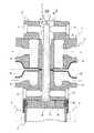
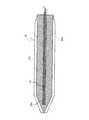
図1は、本発明に係るMOCVD用気化器の一実施形態を示す要部の断面図、図2(A)はセンターロッドの拡大縦断面図、図2(B)はセンターロッドの拡大横断面図である。 FIG. 1 is a cross-sectional view of an essential part showing an embodiment of a vaporizer for MOCVD according to the present invention, FIG. 2 (A) is an enlarged vertical cross-sectional view of a center rod, and FIG. 2 (B) is an enlarged cross-sectional view of the center rod. FIG.
図1において、気化器1は、分散器(分散部本体)2に形成されたキャリアガス導入穴に挿入されてキャリアガス導入穴の内壁との協働によりガス通路5を形成するセンターロッド35と、分散器2のキャリアガス導入穴の外周側に配置されてガス通路5内を冷却する冷却経路6と、センターロッド35の軸線方向に沿い且つセンターロッド35の略全長に跨って形成された冷却部材挿入穴35aと、冷却部材挿入穴35a内に配置されてセンターロッド35を冷却する冷却部材36と、を備えている。 In FIG. 1, a
また、分散器2には、その複数個所に形成されてガス通路5の中途部に複数の薄膜形成材料を供給する薄膜形成材料供給部27〜30(図1では、対向配置された薄膜形成材料供給部28,29のみ図示)が設けられている。 Further, the
この際、冷却経路6と冷却部材36とは、少なくとも薄膜形成材料供給部27〜30の付近からガス通路5の下流端付近に跨って配置されている。 Under the present circumstances, the
また、分散器2で複数の薄膜形成材料を分散させたキャリアガスを気化する気化部が反応管3とヒータ4とで構成されている。 In addition, a vaporizing section that vaporizes a carrier gas in which a plurality of thin film forming materials are dispersed by the
以下、本発明の具体的な構成を説明する。 The specific configuration of the present invention will be described below.
本発明の気化器1にあっては、分散部を構成する分散器2の内部に形成されたガス通路5と、ガス通路5に連通するようにガス供給管18に形成されたキャリアガス導入用のガス導入口18aと、ガス通路5を通過するキャリアガスに原料溶液を供給して原料溶液をミスト化するための薄膜形成材料供給部27〜30と、そのミスト化された原料溶液を含むキャリアガスを気化部に送るための終端噴射口5bと、ガス通路5内を流れるキャリアガスを冷却するための冷却水が循環する冷却部としての冷却経路6と、一端がMOCVD装置の反応管に接続され、他端が分散器2の終端噴射口5bに接続された反応管3と、反応管3を加熱するためのヒータ4と、を備えている。 In the
分散器2の内部は円筒状の中空とされ、この中空のキャリアガス導入穴にセンターロッド35が挿入されており、分散器2の内壁とセンターロッド35とによりガス通路5が形成されている。尚、キャリアガス導入穴は円筒状に限らず、他の形状でも良く、例えば、円錐状とするのが好ましい。円錐状のキャリアガス導入穴の円巣の角度としては、0〜45°が好ましく、8〜20°がより好ましい。他の実施例においても同様である。 The inside of the
尚、ガス通路の断面積は0.10〜0.5mm2が好ましい。0.10mm2未満では加工が困難である。0.5mm2を超えるとキャリアガスを高速化するために高圧で且つ大流量のキャリアガスを用いる必要が生じてしまう。 The cross-sectional area of the gas passage is preferably 0.10 to 0.5 mm2. If it is less than 0.10 mm2, processing is difficult. If it exceeds 0.5
大流量のキャリアガスを用いると、反応チャンバーを減圧(例:1.0Torr)に維持するために、大容量の大型真空ポンプが必要になる。排気容量が、1万リットル/min.(at,1.0Torr)を超える真空ポンプの採用は困難であるから、工業的な実用化を図るためには、適正な流量即ちガス通路面積0.10〜0.5mm2が好ましい。 When a large flow rate of carrier gas is used, a large-capacity large vacuum pump is required to maintain the reaction chamber at a reduced pressure (eg, 1.0 Torr). The exhaust capacity is 10,000 liters / min. Since it is difficult to employ a vacuum pump exceeding (at, 1.0 Torr), an appropriate flow rate, that is, a gas passage area of 0.10 to 0.5
このガス通路5の一端にはガス導入口18aが設けられている。このガス導入口18aにはキャリアガス(例えばN2,Ar,Heの少なくとも何れか)のガスボンベ11が接続されている。 A
分散器2の略中央部分には、ガス通路5に連通せしめて薄膜形成材料供給部27〜30を設け、原料溶液をガス通路5に滴下導入して、原料溶液をガス通路5を通過するキャリアガスに分散させることで原料ガスとすることができる。 In the substantially central portion of the
ガス通路5の一端には、反応管3に連通する終端噴射口5bを形成した輻射防止部37が設けられている。 At one end of the
分散器2には、冷却水を循環させるための冷却経路6が形成されており、この冷却経路6に冷却水を流すことによりガス通路5内を流れるキャリアガスを冷却する。尚、この冷却経路6の代わりにペルチェ素子等を設置して冷却してもよい。また、ガス通路5内はヒータ4による熱影響を受けるためガス通路5内において原料溶液の溶剤と有機金属錯体との同時気化が生ずることなく、溶剤のみの気化が生じてしまう。そこで、ガス通路5内を流れる原料溶液が分散したキャリアガスを冷却することにより溶剤のみの気化を防止するのが好ましい。この際、薄膜形成材料供給部27〜30よりもガス通路5の下流側に対する冷却は特に重要であることから、少なくとも薄膜形成材料供給部27〜30よりも下流側のガス通路5内の冷却を行うのが好ましい。尚、その冷却温度は、溶剤の沸点以下の温度である(例えば、THFでは67℃以下)。特に、終端噴射口5bにおける温度が重要である。 A
そこで、図2に示すように、本発明のセンターロッド35には、その軸線上に冷却部材挿入穴35aを形成すると共に、その冷却部材挿入穴35aにセンターロッド35を直接内部冷却する冷却部材36が配置されている。尚、センターロッド35の外周には、適用する薄膜形成材料を効率良く下流側へと供給するために薄膜形成材料供給部27〜30と1対1で対応した複数のガイド溝35bが形成されている。 Therefore, as shown in FIG. 2, the
尚、センターロッド35は、図2(A)に示すように、中途部から始端上流口5a側に向かって互いに軸心方向に接近するように先細りとされている。 As shown in FIG. 2 (A), the
この際、先端部は、円錐(又は截頭円錐)形状とするのが好ましく、この先端形状に沿うように分散器2のキャリアガス導入穴を形成することによりガス通路5が終端噴射口5bで合流(合流部)することとなる。尚、先端部37aは、角錐(又は截頭角錐)形状としても良い。この際、その角数(面数)は、4つの薄膜形成材料供給部27〜30に対応して四角錐とするが、ガス通路5の本数、即ち、リザーブタンク14〜17の数に相当する原料溶液(薄膜形成原料)の数に対応した面数の多角錐とすることができる。尚、この場合にはその各面にガイド溝35bが形成されることは勿論である。また、終端噴射口5bを合流部としているが、この合流部は終端噴射口5bよりもキャリアガス搬送方向上流側に設けても良い。 At this time, it is preferable that the tip portion has a conical (or frustoconical) shape, and the carrier gas introduction hole of the
冷却部材36は、例えば、外側を吸熱側とし且つ内側を放熱側とした円筒形状のものが用いられている。尚、図2(B)において、36a,36bはその配線コードである。 As the cooling
尚、冷却部材36は、例えば、図3に示すように、吸熱側を冷却部材挿入穴35aの内部に位置させ且つ放熱側を冷却部材挿入穴35aの外部に位置させたヒートパイプや、図4に示すように、冷却水を循環させる螺旋状(又は略U字状)の冷水パイプ等、特に、限定されるものではないが、冷却温度に応じた形状(太さ等)とするのが好ましい。また、冷却部材36を、センターロッド35に直接形成した冷却通路等とはしないことにより、センターロッド35の形成の容易化並びに、分解等のメンテナンスの容易化に貢献することができる。さらに、冷却部材36は、センターロッド35の略全長に跨って配置することにより、事前にキャリアガスを冷却することができるが、その冷却温度を高く確保することができれば、少なくとも薄膜形成材料供給部27〜30よりも下流側のガス通路5内の冷却を行う構成でも良い。 As shown in FIG. 3, for example, the cooling
終端噴射口5bを形成した輻射防止部37は、Oリング等のシール部材38,39によって密閉性が確保されている。尚、この輻射防止部37は、例えば、テフロン(登録商標)、ステンレス、セラミック等の熱伝導性の優れた材料により構成することが好ましい。 The
本発明者の知見によれば、従来技術に示したように、ガス通路5の外側のみを冷却した構成では、気化部における熱が、輻射熱として終端噴射口5bを介してガス通路5内におけるガスを過熱してしまう。従って、冷却水により冷却したとしてもキャリアガス中の低融点成分が終端噴射口5bの近傍に析出してしまう。 According to the knowledge of the present inventor, as shown in the prior art, in the configuration in which only the outside of the
そこで、上述した冷却部材36を配置すると共に、輻射防止部37をさらに配置することにより、このような輻射熱がキャリアガスに伝播することを一層抑制することが可能となる。従って、終端噴射口5bの断面積は、ガス通路5の断面積よりも小さくする(例えば、1/2以下、より好ましくは1/3以下)ことが好ましい。また、終端噴射口5bを微小化することが好ましい。特に、噴出するガス流速が亜音速となる寸法に微小化することが好ましい。 Therefore, it is possible to further suppress the propagation of such radiant heat to the carrier gas by disposing the above-described
また、終端噴射口5bの長さは、終端噴射口5bの断面寸法の5倍以上であることが好ましく、10倍以上であることがより好ましい。 Further, the length of the
また、分散器2を冷却することにより、長期間にわる使用に対してもガス通路5内(特に終端噴射口5b)における炭化物による閉塞を生ずることが抑制されている。 Further, by cooling the
分散器2の下流側は、反応管3が接続されている。分散器2と反応管3との接続は継手等によって行うことができる。 A
上記の構成においては、分散器2に形成されたキャリアガス導入穴の内壁とキャリアガス導入穴に挿入されたセンターロッド35との間に形成されたガス通路5にキャリアガスを導入すると共に、ガス通路5の中途部複数箇所から薄膜形成材料を導入してキャリアガスに薄膜形成材料を分散させると共に、少なくともガス通路5の中途部複数箇所から導入された薄膜形成材料を分散させたキャリアガスを、分散器2に配置した冷却経路6とセンターロッド35に配置した冷却部材36とで冷却しつつ合流部に薄膜形成材料を分散させたキャリアガスを案内した後に、ガス通路5の下流端部に配置されたセンターロッド35先端によって互いに接近する方向に案内される合流部にて薄膜形成材料を分散させたキャリアガスを合流させたうえで、ヒータ4で加熱して気化した後、図示を略する薄膜成膜装置へと送り込まれる。In the above configuration, the carrier gas is introduced into the
1…気化器
2…分散器(分散部本体)
3…反応管
4…ヒータ
5…ガス通路
5a…始端上流口
5b…終端噴射口(合流部)
6…冷却通路
7…センターロッド
8…ピン
9…ピン
10…供給部
11…ガスボンベ
12…酸素ボンベ
13…貯水タンク
14…リザーブタンク
15…リザーブタンク
16…リザーブタンク
17…リザーブタンク
18…ガス供給管
18b…マスフローコントローラ
18b…マスフローコントローラ
19…酸素供給管
19a…バルブ
19b…マスフローコントローラ
19c…バルブ
20…給水管
20a…バルブ
21…配水管
22…液体供給管
22a…バルブ
22b…マスフローコントローラ
22c…バルブ
23…液体供給管
23a…バルブ
23b…マスフローコントローラ
23c…バルブ
24…液体供給管
24a…バルブ
24b…マスフローコントローラ
24c…バルブ
25…液体供給管
25a…バルブ
25b…マスフローコントローラ
25c…バルブ
26…多岐管
26a…バルブ
26b…バルブ
26c…バルブ
26d…バルブ
26e…エアパージ
26f…バルブ
27…薄膜形成材料供給部
28…薄膜形成材料供給部
29…薄膜形成材料供給部
30…薄膜形成材料供給部
31…接続部
32…接続部
33…冷却システム
35…センターロッド
35a…冷却部材挿入穴
35b…ガイド溝
36…冷却部材
37…輻射防止部
38…シール部材
39…シール部材1 ...
DESCRIPTION OF
6 ...
Claims (11)
Translated fromJapanese前記冷却部と前記冷却部材は、少なくとも薄膜形成材料供給部から前記ガス通路の下流端付近に跨って配置されていることを特徴とする気化器。A center rod that is inserted over the entire length of the carrier gas introduction hole formed in the dispersion part body and forms a gas passage in cooperation with the inner wall of the carrier gas introduction hole, and is formed at a plurality of locations of the dispersion part body. A thin film forming material supply unit that supplies a plurality of thin film forming materials to a middle part of the gas passage, and a cooling unit that is disposed on the outer peripheral side of the carrier gas introduction hole of the dispersion unit main body and cools the gas passage. A cooling member insertion hole formed along the axial direction of the center rod and over substantially the entire length of the center rod, and a cooling member disposed in the cooling member insertion hole to cool the center rod,
The vaporizer, wherein the cooling unit and the cooling member are disposed across at least thevicinity of the downstream end of the gas passage from the thin film forming material supply unit.
前記センターロッドの外周に形成され且つ適用する薄膜形成材料と1対1で対応した複数のガイド溝を備えていることを特徴とするセンターロッド。A center rod used in the vaporizer according to claim 1 or 2, or the vaporizer for MOCVD according to claim 3,
A center rod comprising a plurality of guide grooves formed on an outer periphery of the center rod and corresponding one-to-one with a thin film forming material to be applied.
少なくとも薄膜形成材料供給部から前記ガス通路の下流端付近に跨って冷却しつつ前記ガス通路内を搬送することを特徴とするキャリアガスの冷却分散方法。While introducing a carrier gas in which a plurality of thin film forming materials are dispersed into a gas passage formed between an inner wall of a carrier gas introduction hole formed in the dispersion body and a center rod inserted into the carrier gas introduction hole The carrier gas in which the thin film forming material is dispersed is cooled across thevicinity of the downstream end of the gas passage from at least the thin film forming material supply unit by the cooling unit arranged in the dispersion unit main body and the cooling member arranged in the center rod. A carrier gas cooling and dispersing method, wherein the carrier gas is conveyed in the gas passage.
少なくとも前記ガス通路の中途部複数箇所から導入された薄膜形成材料を分散させたキャリアガスを、前記分散部本体に配置した冷却部と前記センターロッドに配置した冷却部材とで
少なくとも薄膜形成材料供給部から前記ガス通路の下流端付近に跨って冷却しつつ前記合流部に前記薄膜形成材料を分散させたキャリアガスを案内することを特徴とするキャリアガスの気化方法。The carrier gas is introduced into the gas passage formed between the inner wall of the carrier gas introduction hole formed in the dispersion body and the center rod inserted into the carrier gas introduction hole, and a plurality of locations in the middle of the gas passage After the thin film forming material is introduced from the carrier gas, the thin film forming material is dispersed in a carrier gas, and then the thin film is formed at a junction portion guided in a direction approaching each other by a center rod tip disposed at a downstream end portion of the gas passage. A method of vaporizing a carrier gas that is vaporized after the carrier gas in which the forming material is dispersed is merged,
At least a thin film forming material supply unit including a cooling unit disposed in the dispersion unit main body and a cooling member disposed in the center rod with a carrier gas in which a thin film forming material introduced from a plurality of locations in the middle of the gas passage is dispersed. The carrier gas vaporizing method is characterized in that the carrier gas in which the thin film forming material is dispersed is guided to the joining portion while cooling over thevicinity of the downstream end of the gas passage.
Priority Applications (7)
| Application Number | Priority Date | Filing Date | Title |
|---|---|---|---|
| JP2009023063AJP5614935B2 (en) | 2009-02-03 | 2009-02-03 | Vaporizer, vaporizer for MOCVD using this vaporizer, center rod used in these vaporizers or vaporizer for MOCVD, and carrier gas distribution |
| KR1020167029843AKR20160128441A (en) | 2009-02-03 | 2010-01-27 | Carburetor, carburetor for mocvd using same, center rod for use in the carburetor or carburetor for mocvd, method for dispersing carrier gas, and method for vaporizing carrier gas |
| PCT/JP2010/051054WO2010090112A1 (en) | 2009-02-03 | 2010-01-27 | Carburetor, carburetor for mocvd using same, center rod for use in the carburetor or carburetor for mocvd, method for dispersing carrier gas, and method for vaporizing carrier gas |
| KR20117020560AKR20120005440A (en) | 2009-02-03 | 2010-01-27 | Carburetor, the MOD COB vaporizer which uses this vaporizer, the center rod used for these vaporizers or the MOBV vaporizer, the dispersion method of carrier gas, and the vaporization method of carrier gas |
| US13/147,668US8897627B2 (en) | 2009-02-03 | 2010-01-27 | Carburetor, carburetor for MOCVD using same, center rod for use in the carburetor or carburetor for MOCVD, method for dispersing carrier gas, and method for vaporizing carrier gas |
| US14/520,537US9020332B2 (en) | 2009-02-03 | 2014-10-22 | Center rod for use in the carburetor or carburetor for MOCVD |
| US14/520,457US9108120B2 (en) | 2009-02-03 | 2014-10-22 | Method for cooling and dispersing a carrier gas, and method for vaporizing a carrier gas |
Applications Claiming Priority (1)
| Application Number | Priority Date | Filing Date | Title |
|---|---|---|---|
| JP2009023063AJP5614935B2 (en) | 2009-02-03 | 2009-02-03 | Vaporizer, vaporizer for MOCVD using this vaporizer, center rod used in these vaporizers or vaporizer for MOCVD, and carrier gas distribution |
Related Child Applications (1)
| Application Number | Title | Priority Date | Filing Date |
|---|---|---|---|
| JP2014108382ADivisionJP2014159644A (en) | 2014-05-26 | 2014-05-26 | Vaporizer, mocvd vaporizer using this vaporizer, center rod used in these vaporizers, carrier gas dispersion method and carrier gas vaporization method |
Publications (2)
| Publication Number | Publication Date |
|---|---|
| JP2010180433A JP2010180433A (en) | 2010-08-19 |
| JP5614935B2true JP5614935B2 (en) | 2014-10-29 |
Family
ID=42542012
Family Applications (1)
| Application Number | Title | Priority Date | Filing Date |
|---|---|---|---|
| JP2009023063AExpired - Fee RelatedJP5614935B2 (en) | 2009-02-03 | 2009-02-03 | Vaporizer, vaporizer for MOCVD using this vaporizer, center rod used in these vaporizers or vaporizer for MOCVD, and carrier gas distribution |
Country Status (4)
| Country | Link |
|---|---|
| US (3) | US8897627B2 (en) |
| JP (1) | JP5614935B2 (en) |
| KR (2) | KR20120005440A (en) |
| WO (1) | WO2010090112A1 (en) |
Families Citing this family (2)
| Publication number | Priority date | Publication date | Assignee | Title |
|---|---|---|---|---|
| JP5993363B2 (en)* | 2011-02-28 | 2016-09-14 | 株式会社渡辺商行 | Vaporizer and vaporization method |
| KR20160147482A (en)* | 2015-06-15 | 2016-12-23 | 삼성전자주식회사 | Apparatus for manufacturing Semiconductor Devices Having a Gas Mixing Part |
Family Cites Families (13)
| Publication number | Priority date | Publication date | Assignee | Title |
|---|---|---|---|---|
| US4111365A (en)* | 1973-12-26 | 1978-09-05 | Isuzu Motors Limited | Fuel injection system and its nozzle holder |
| TW322602B (en)* | 1996-04-05 | 1997-12-11 | Ehara Seisakusho Kk | |
| JP3913841B2 (en)* | 1997-07-02 | 2007-05-09 | 本田技研工業株式会社 | Injection valve |
| JP3470055B2 (en)* | 1999-01-22 | 2003-11-25 | 株式会社渡邊商行 | MOCVD vaporizer and raw material solution vaporization method |
| US7246796B2 (en)* | 2001-01-18 | 2007-07-24 | Masayuki Toda | Carburetor, various types of devices using the carburetor, and method of vaporization |
| JP5016416B2 (en)* | 2001-01-18 | 2012-09-05 | 株式会社渡辺商行 | Vaporizer and vaporization method |
| KR20040007439A (en)* | 2001-01-18 | 2004-01-24 | 가부시키가이샤 와타나베 쇼코 | Ferroelectric thin film, metal thin film or oxide thin film, and method and apparatus for preparation thereof, and electric or electronic device using said thin film |
| JP2004010969A (en)* | 2002-06-07 | 2004-01-15 | Taiheiyo Cement Corp | Roller for rolling |
| JP4192008B2 (en) | 2003-02-18 | 2008-12-03 | 株式会社渡辺商行 | Vaporizer, vaporizer cleaning method, and apparatus using vaporizer |
| JP2004273766A (en)* | 2003-03-07 | 2004-09-30 | Watanabe Shoko:Kk | Vaporizing device and film forming device using it, and method for vaporising and film forming |
| JP2005072194A (en)* | 2003-08-22 | 2005-03-17 | Watanabe Shoko:Kk | Dispersing device for vaporizer, vaporizer for mocvd using the dispersing device, rod used for the dispersing device or vaporizer, method of dispersing carrier gas, and method of vaporizing carrier gas |
| JP2005072195A (en)* | 2003-08-22 | 2005-03-17 | Watanabe Shoko:Kk | Dispersing device for vaporizer, vaporizer for mocvd using the same, and method of vaporizing carrier gas |
| JP5993363B2 (en)* | 2011-02-28 | 2016-09-14 | 株式会社渡辺商行 | Vaporizer and vaporization method |
- 2009
- 2009-02-03JPJP2009023063Apatent/JP5614935B2/ennot_activeExpired - Fee Related
- 2010
- 2010-01-27USUS13/147,668patent/US8897627B2/ennot_activeExpired - Fee Related
- 2010-01-27WOPCT/JP2010/051054patent/WO2010090112A1/enactiveApplication Filing
- 2010-01-27KRKR20117020560Apatent/KR20120005440A/ennot_activeCeased
- 2010-01-27KRKR1020167029843Apatent/KR20160128441A/ennot_activeCeased
- 2014
- 2014-10-22USUS14/520,537patent/US9020332B2/ennot_activeExpired - Fee Related
- 2014-10-22USUS14/520,457patent/US9108120B2/ennot_activeExpired - Fee Related
Also Published As
| Publication number | Publication date |
|---|---|
| US20150053137A1 (en) | 2015-02-26 |
| JP2010180433A (en) | 2010-08-19 |
| US9108120B2 (en) | 2015-08-18 |
| US9020332B2 (en) | 2015-04-28 |
| US20120040098A1 (en) | 2012-02-16 |
| US20150069642A1 (en) | 2015-03-12 |
| WO2010090112A1 (en) | 2010-08-12 |
| KR20120005440A (en) | 2012-01-16 |
| US8897627B2 (en) | 2014-11-25 |
| KR20160128441A (en) | 2016-11-07 |
Similar Documents
| Publication | Publication Date | Title |
|---|---|---|
| US6269221B1 (en) | Liquid feed vaporization system and gas injection device | |
| CN100595910C (en) | Vaporizer, various devices using the vaporizer, and vaporization method | |
| KR100496914B1 (en) | Vaporizer | |
| US20060278166A1 (en) | Vaporizer, various devices using the same, and vaporizing method | |
| JP5614935B2 (en) | Vaporizer, vaporizer for MOCVD using this vaporizer, center rod used in these vaporizers or vaporizer for MOCVD, and carrier gas distribution | |
| KR20050113549A (en) | Vaporizer, various apparatuses including the same and method of vaporization | |
| JP2005101454A (en) | Vaporizer | |
| KR20040091738A (en) | Method of depositing cvd thin film | |
| JP2014159644A5 (en) | ||
| JP2014159644A (en) | Vaporizer, mocvd vaporizer using this vaporizer, center rod used in these vaporizers, carrier gas dispersion method and carrier gas vaporization method | |
| KR20060121819A (en) | Thin film deposition apparatus | |
| JP2008001994A (en) | Evaporator and evaporation method | |
| JP2005072195A (en) | Dispersing device for vaporizer, vaporizer for mocvd using the same, and method of vaporizing carrier gas | |
| JP2005072194A (en) | Dispersing device for vaporizer, vaporizer for mocvd using the dispersing device, rod used for the dispersing device or vaporizer, method of dispersing carrier gas, and method of vaporizing carrier gas | |
| KR100507961B1 (en) | Liquid raw material gasification system and gas injection device | |
| WO2002058129A1 (en) | Ferroelectric thin film, metal thin film or oxide thin film, and method and apparatus for preparation thereof, and electric or electronic device using said thin film | |
| JP2010067995A (en) | Vaporization method | |
| JP2000226668A (en) | Vaporizer | |
| JP4238239B2 (en) | Vaporization method | |
| JP2015039001A (en) | Vaporizer | |
| JP5542103B2 (en) | Vaporizer | |
| JP2012169671A (en) | Vaporizer | |
| JP2008205506A (en) | Vaporizer, and various apparatus and vaporizing method using the same |
Legal Events
| Date | Code | Title | Description |
|---|---|---|---|
| A621 | Written request for application examination | Free format text:JAPANESE INTERMEDIATE CODE: A621 Effective date:20120202 | |
| A711 | Notification of change in applicant | Free format text:JAPANESE INTERMEDIATE CODE: A711 Effective date:20120525 | |
| A521 | Request for written amendment filed | Free format text:JAPANESE INTERMEDIATE CODE: A821 Effective date:20120525 | |
| A521 | Request for written amendment filed | Free format text:JAPANESE INTERMEDIATE CODE: A523 Effective date:20120925 | |
| A131 | Notification of reasons for refusal | Free format text:JAPANESE INTERMEDIATE CODE: A131 Effective date:20131023 | |
| A521 | Request for written amendment filed | Free format text:JAPANESE INTERMEDIATE CODE: A523 Effective date:20131224 | |
| A02 | Decision of refusal | Free format text:JAPANESE INTERMEDIATE CODE: A02 Effective date:20140226 | |
| A521 | Request for written amendment filed | Free format text:JAPANESE INTERMEDIATE CODE: A523 Effective date:20140526 | |
| A911 | Transfer to examiner for re-examination before appeal (zenchi) | Free format text:JAPANESE INTERMEDIATE CODE: A911 Effective date:20140723 | |
| TRDD | Decision of grant or rejection written | ||
| A01 | Written decision to grant a patent or to grant a registration (utility model) | Free format text:JAPANESE INTERMEDIATE CODE: A01 Effective date:20140813 | |
| A61 | First payment of annual fees (during grant procedure) | Free format text:JAPANESE INTERMEDIATE CODE: A61 Effective date:20140909 | |
| R150 | Certificate of patent or registration of utility model | Ref document number:5614935 Country of ref document:JP Free format text:JAPANESE INTERMEDIATE CODE: R150 | |
| R250 | Receipt of annual fees | Free format text:JAPANESE INTERMEDIATE CODE: R250 | |
| R250 | Receipt of annual fees | Free format text:JAPANESE INTERMEDIATE CODE: R250 | |
| LAPS | Cancellation because of no payment of annual fees |