JP5612090B2 - How to create a lead for a stimulator - Google Patents
How to create a lead for a stimulatorDownload PDFInfo
- Publication number
- JP5612090B2 JP5612090B2JP2012519636AJP2012519636AJP5612090B2JP 5612090 B2JP5612090 B2JP 5612090B2JP 2012519636 AJP2012519636 AJP 2012519636AJP 2012519636 AJP2012519636 AJP 2012519636AJP 5612090 B2JP5612090 B2JP 5612090B2
- Authority
- JP
- Japan
- Prior art keywords
- electrode
- lead
- electrodes
- lead body
- stimulation
- Prior art date
- Legal status (The legal status is an assumption and is not a legal conclusion. Google has not performed a legal analysis and makes no representation as to the accuracy of the status listed.)
- Expired - Fee Related
Links
- 239000004020conductorSubstances0.000claimsdescription37
- 238000000034methodMethods0.000claimsdescription31
- 125000006850spacer groupChemical group0.000claimsdescription16
- 238000003466weldingMethods0.000claimsdescription6
- 238000000227grindingMethods0.000claimsdescription5
- 238000005304joiningMethods0.000claimsdescription3
- 238000002679ablationMethods0.000claims1
- 230000000638stimulationEffects0.000description54
- 239000000463materialSubstances0.000description27
- 210000004556brainAnatomy0.000description21
- 210000002569neuronAnatomy0.000description20
- 238000004519manufacturing processMethods0.000description16
- 210000003205muscleAnatomy0.000description10
- 230000007704transitionEffects0.000description9
- 229920002635polyurethanePolymers0.000description8
- 239000004814polyurethaneSubstances0.000description8
- 230000008569processEffects0.000description6
- 210000001519tissueAnatomy0.000description6
- 239000004696Poly ether ether ketoneSubstances0.000description5
- 229910052751metalInorganic materials0.000description5
- 239000002184metalSubstances0.000description5
- 230000001537neural effectEffects0.000description5
- 229920002530polyetherether ketonePolymers0.000description5
- -1polyethylenePolymers0.000description5
- 239000010703siliconSubstances0.000description5
- 229910052710siliconInorganic materials0.000description5
- 206010044565TremorDiseases0.000description4
- 239000011810insulating materialSubstances0.000description4
- 238000005259measurementMethods0.000description4
- 230000004044responseEffects0.000description4
- 210000003625skullAnatomy0.000description4
- 239000000560biocompatible materialSubstances0.000description3
- 230000008878couplingEffects0.000description3
- 238000010168coupling processMethods0.000description3
- 238000005859coupling reactionMethods0.000description3
- 238000011049fillingMethods0.000description3
- 238000001746injection mouldingMethods0.000description3
- 238000003780insertionMethods0.000description3
- 230000037431insertionEffects0.000description3
- 150000002739metalsChemical class0.000description3
- 229920003023plasticPolymers0.000description3
- 239000004033plasticSubstances0.000description3
- 208000002740Muscle RigidityDiseases0.000description2
- 239000004698PolyethyleneSubstances0.000description2
- 230000009471actionEffects0.000description2
- 230000008859changeEffects0.000description2
- 239000002131composite materialSubstances0.000description2
- 238000002591computed tomographyMethods0.000description2
- 238000010586diagramMethods0.000description2
- 230000005484gravityEffects0.000description2
- 230000001788irregularEffects0.000description2
- 239000007788liquidSubstances0.000description2
- BASFCYQUMIYNBI-UHFFFAOYSA-NplatinumChemical compound[Pt]BASFCYQUMIYNBI-UHFFFAOYSA-N0.000description2
- 229920000573polyethylenePolymers0.000description2
- 229920000642polymerPolymers0.000description2
- 229920001296polysiloxanePolymers0.000description2
- WFKWXMTUELFFGS-UHFFFAOYSA-NtungstenChemical compound[W]WFKWXMTUELFFGS-UHFFFAOYSA-N0.000description2
- 239000010937tungstenSubstances0.000description2
- 229910052721tungstenInorganic materials0.000description2
- 208000000094Chronic PainDiseases0.000description1
- 206010010904ConvulsionDiseases0.000description1
- 208000012661DyskinesiaDiseases0.000description1
- 208000014094Dystonic diseaseDiseases0.000description1
- 208000030814Eating diseaseDiseases0.000description1
- 239000004593EpoxySubstances0.000description1
- 208000019454Feeding and Eating diseaseDiseases0.000description1
- 208000023105Huntington diseaseDiseases0.000description1
- WTDRDQBEARUVNC-LURJTMIESA-NL-DOPAChemical compoundOC(=O)[C@@H](N)CC1=CC=C(O)C(O)=C1WTDRDQBEARUVNC-LURJTMIESA-N0.000description1
- WTDRDQBEARUVNC-UHFFFAOYSA-NL-DopaNatural productsOC(=O)C(N)CC1=CC=C(O)C(O)=C1WTDRDQBEARUVNC-UHFFFAOYSA-N0.000description1
- 239000004944Liquid Silicone RubberSubstances0.000description1
- 208000019022Mood diseaseDiseases0.000description1
- 208000002193PainDiseases0.000description1
- 208000018737Parkinson diseaseDiseases0.000description1
- 229920002396PolyureaPolymers0.000description1
- 229910000831SteelInorganic materials0.000description1
- RTAQQCXQSZGOHL-UHFFFAOYSA-NTitaniumChemical compound[Ti]RTAQQCXQSZGOHL-UHFFFAOYSA-N0.000description1
- NRTOMJZYCJJWKI-UHFFFAOYSA-NTitanium nitrideChemical compound[Ti]#NNRTOMJZYCJJWKI-UHFFFAOYSA-N0.000description1
- 239000002253acidSubstances0.000description1
- 239000000853adhesiveSubstances0.000description1
- 230000001070adhesive effectEffects0.000description1
- 229910045601alloyInorganic materials0.000description1
- 239000000956alloySubstances0.000description1
- 230000015572biosynthetic processEffects0.000description1
- 210000005013brain tissueAnatomy0.000description1
- 239000002775capsuleSubstances0.000description1
- 238000005266castingMethods0.000description1
- 239000011248coating agentSubstances0.000description1
- 238000000576coating methodMethods0.000description1
- 238000005520cutting processMethods0.000description1
- 230000001419dependent effectEffects0.000description1
- 238000013461designMethods0.000description1
- 235000014632disordered eatingNutrition0.000description1
- 210000001951dura materAnatomy0.000description1
- 208000010118dystoniaDiseases0.000description1
- 230000000694effectsEffects0.000description1
- 238000005516engineering processMethods0.000description1
- 206010015037epilepsyDiseases0.000description1
- 239000003822epoxy resinSubstances0.000description1
- 201000006517essential tremorDiseases0.000description1
- 238000005530etchingMethods0.000description1
- 239000012467final productSubstances0.000description1
- 238000002347injectionMethods0.000description1
- 239000007924injectionSubstances0.000description1
- 229910052741iridiumInorganic materials0.000description1
- GKOZUEZYRPOHIO-UHFFFAOYSA-Niridium atomChemical compound[Ir]GKOZUEZYRPOHIO-UHFFFAOYSA-N0.000description1
- 238000000608laser ablationMethods0.000description1
- 229960004502levodopaDrugs0.000description1
- 238000002595magnetic resonance imagingMethods0.000description1
- 230000003340mental effectEffects0.000description1
- 239000000203mixtureSubstances0.000description1
- 238000000465mouldingMethods0.000description1
- 239000012811non-conductive materialSubstances0.000description1
- 229910052697platinumInorganic materials0.000description1
- HWLDNSXPUQTBOD-UHFFFAOYSA-Nplatinum-iridium alloyChemical class[Ir].[Pt]HWLDNSXPUQTBOD-UHFFFAOYSA-N0.000description1
- 229920000647polyepoxidePolymers0.000description1
- 239000002861polymer materialSubstances0.000description1
- 229920003226polyurethane ureaPolymers0.000description1
- 239000000047productSubstances0.000description1
- 230000008707rearrangementEffects0.000description1
- 238000011160researchMethods0.000description1
- 229920002379silicone rubberPolymers0.000description1
- 239000010935stainless steelSubstances0.000description1
- 229910001220stainless steelInorganic materials0.000description1
- 239000010959steelSubstances0.000description1
- 239000000758substrateSubstances0.000description1
- 230000001225therapeutic effectEffects0.000description1
- 229910052719titaniumInorganic materials0.000description1
- 239000010936titaniumSubstances0.000description1
Images


Classifications
- H—ELECTRICITY
- H01—ELECTRIC ELEMENTS
- H01R—ELECTRICALLY-CONDUCTIVE CONNECTIONS; STRUCTURAL ASSOCIATIONS OF A PLURALITY OF MUTUALLY-INSULATED ELECTRICAL CONNECTING ELEMENTS; COUPLING DEVICES; CURRENT COLLECTORS
- H01R13/00—Details of coupling devices of the kinds covered by groups H01R12/70 or H01R24/00 - H01R33/00
- H01R13/56—Means for preventing chafing or fracture of flexible leads at outlet from coupling part
- H01R13/567—Traverse cable outlet or wire connection
- A—HUMAN NECESSITIES
- A61—MEDICAL OR VETERINARY SCIENCE; HYGIENE
- A61N—ELECTROTHERAPY; MAGNETOTHERAPY; RADIATION THERAPY; ULTRASOUND THERAPY
- A61N1/00—Electrotherapy; Circuits therefor
- A61N1/02—Details
- A61N1/04—Electrodes
- A61N1/05—Electrodes for implantation or insertion into the body, e.g. heart electrode
- A61N1/0526—Head electrodes
- A61N1/0529—Electrodes for brain stimulation
- A61N1/0534—Electrodes for deep brain stimulation
- H—ELECTRICITY
- H01—ELECTRIC ELEMENTS
- H01R—ELECTRICALLY-CONDUCTIVE CONNECTIONS; STRUCTURAL ASSOCIATIONS OF A PLURALITY OF MUTUALLY-INSULATED ELECTRICAL CONNECTING ELEMENTS; COUPLING DEVICES; CURRENT COLLECTORS
- H01R4/00—Electrically-conductive connections between two or more conductive members in direct contact, i.e. touching one another; Means for effecting or maintaining such contact; Electrically-conductive connections having two or more spaced connecting locations for conductors and using contact members penetrating insulation
- H01R4/58—Electrically-conductive connections between two or more conductive members in direct contact, i.e. touching one another; Means for effecting or maintaining such contact; Electrically-conductive connections having two or more spaced connecting locations for conductors and using contact members penetrating insulation characterised by the form or material of the contacting members
- H01R4/62—Connections between conductors of different materials; Connections between or with aluminium or steel-core aluminium conductors
- H—ELECTRICITY
- H01—ELECTRIC ELEMENTS
- H01R—ELECTRICALLY-CONDUCTIVE CONNECTIONS; STRUCTURAL ASSOCIATIONS OF A PLURALITY OF MUTUALLY-INSULATED ELECTRICAL CONNECTING ELEMENTS; COUPLING DEVICES; CURRENT COLLECTORS
- H01R43/00—Apparatus or processes specially adapted for manufacturing, assembling, maintaining, or repairing of line connectors or current collectors or for joining electric conductors
- Y—GENERAL TAGGING OF NEW TECHNOLOGICAL DEVELOPMENTS; GENERAL TAGGING OF CROSS-SECTIONAL TECHNOLOGIES SPANNING OVER SEVERAL SECTIONS OF THE IPC; TECHNICAL SUBJECTS COVERED BY FORMER USPC CROSS-REFERENCE ART COLLECTIONS [XRACs] AND DIGESTS
- Y10—TECHNICAL SUBJECTS COVERED BY FORMER USPC
- Y10T—TECHNICAL SUBJECTS COVERED BY FORMER US CLASSIFICATION
- Y10T29/00—Metal working
- Y10T29/49—Method of mechanical manufacture
- Y10T29/49002—Electrical device making
- Y10T29/49117—Conductor or circuit manufacturing
Landscapes
- Health & Medical Sciences (AREA)
- Engineering & Computer Science (AREA)
- Animal Behavior & Ethology (AREA)
- General Health & Medical Sciences (AREA)
- Biomedical Technology (AREA)
- Nuclear Medicine, Radiotherapy & Molecular Imaging (AREA)
- Radiology & Medical Imaging (AREA)
- Life Sciences & Earth Sciences (AREA)
- Cardiology (AREA)
- Heart & Thoracic Surgery (AREA)
- Public Health (AREA)
- Veterinary Medicine (AREA)
- Neurology (AREA)
- Neurosurgery (AREA)
- Psychology (AREA)
- Manufacturing & Machinery (AREA)
- Electrotherapy Devices (AREA)
Description
Translated fromJapanese本発明は、刺激装置用のリードを作成する方法に関する。The present invention relatesto a method of creating a lead for a stimulator.
脳深部刺激は、例えば、パーキンソン病、ジストニー、本態性振戦、慢性疼痛、ハンチントン病、レボドパ誘発性運動障害及び筋硬直、動作緩慢、てんかん及び発作、摂食障害、並びに気分障害を含む様々な病気の治療に有用な場合がある。通常は、先端又は先端近くに刺激電極を有するリードが、脳内の標的ニューロンに刺激を与える。磁気共鳴画像(MRI)又はコンピュータ断層撮影(CT)スキャンが、標的ニューロンに所望の刺激を与えるために刺激電極をどこに配置すべきかを決定するための開始点となることができる。 Deep brain stimulation can occur in a variety of ways, including, for example, Parkinson's disease, dystonia, essential tremor, chronic pain, Huntington's disease, levodopa-induced dyskinesia and muscle rigidity, slow movement, epilepsy and seizures, eating disorders, and mood disorders May be useful in treating illness. Usually, a lead having a stimulation electrode at or near the tip provides stimulation to target neurons in the brain. Magnetic resonance imaging (MRI) or computed tomography (CT) scanning can be the starting point for determining where the stimulation electrodes should be placed to deliver the desired stimulation to the target neuron.
挿入すると、リードの長さに沿って電流が導入されて脳内の標的ニューロンを刺激する。この刺激は、通常はリード上に配置されたリングの形をした電極によって与えられる。電流は、各電極から全ての方向にリードの軸に沿って任意の長さで等しく放出される。電極の形状に起因して、電流の径方向選択性は最小限に抑えられる。これにより、近隣の神経組織が不必要に刺激され、望ましくない副作用が生じ、適正な治療効果を得るための継続時間が長くなる。 Upon insertion, current is introduced along the length of the lead to stimulate target neurons in the brain. This stimulation is usually provided by a ring-shaped electrode placed on the lead. Current is equally emitted from each electrode in any direction along the lead axis in any direction. Due to the shape of the electrodes, the radial selectivity of the current is minimized. This unnecessarily stimulates nearby neural tissue, causes undesirable side effects, and increases the duration to obtain a proper therapeutic effect.
研究では、現在の製造方法で生産される脳深部刺激リードは信頼性が低く、不具合を起こしやすいことが示されている。ある研究では、リード製品によってはリード破損率が約6.8%〜12.4%と報告されており、平均して260日〜390日で破損が生じることが示されている。従って、多くの場合、短い期間内に補正処置が必要となる。この補正処置が、患者にとって肉体的、精神的及び経済的に重い負担となる。 Research has shown that deep brain stimulation leads produced by current manufacturing methods are unreliable and prone to failure. Some studies have reported lead failure rates of about 6.8% to 12.4%, depending on the lead product, indicating an average of 260 to 390 days of failure. Therefore, in many cases, corrective action is required within a short period of time. This corrective action places a heavy physical, mental and economic burden on the patient.
いくつかの実施形態では、刺激装置用のリードを作成する方法が、少なくとも2つの厚壁部分により分離された少なくとも2つの薄壁部分を含む少なくとも1つのリング形状の予備電極を形成するステップと、少なくとも1つの予備電極をリード本体の遠位端近くに配置するステップと、少なくとも1つの予備電極の各厚壁部分に少なくとも1つの導体を接合するステップと、リード本体及び少なくとも1つの予備電極を研削して少なくとも1つの予備電極の薄壁部分を除去し、少なくとも1つの予備電極の厚壁部分から複数の分割電極を形成するステップとを含む。 In some embodiments, a method of creating a lead for a stimulator forms at least one ring-shaped pre-electrode that includes at least two thin wall portions separated by at least two thick wall portions; Disposing at least one spare electrode near the distal end of the lead body; joining at least one conductor to each thick wall portion of the at least one spare electrode; and grinding the lead body and the at least one spare electrode. Removing the thin wall portion of the at least one preliminary electrode and forming a plurality of divided electrodes from the thick wall portion of the at least one preliminary electrode.
いくつかの実施形態では、刺激装置用のリードを作成する方法が、複数の電極をプレートに結合するステップと、複数の電極の各々に個々の導体を接合するステップと、プレートを円筒に形成し、導体が円筒の管腔を貫いて延びるようにするステップと、円筒の管腔を絶縁材料で満たしてリードアセンブリを形成するステップと、プレートを除去して複数の電極を露出させるステップとを含む。 In some embodiments, a method of creating a lead for a stimulator includes coupling a plurality of electrodes to a plate, joining individual conductors to each of the plurality of electrodes, and forming the plate into a cylinder. Allowing the conductor to extend through the cylindrical lumen; filling the cylindrical lumen with an insulating material to form a lead assembly; and removing the plate to expose the plurality of electrodes. .
いくつかの実施形態では、刺激装置用のリードを作成する方法が、複数の電極を鋳型内に配置し、可撓性のキャリア内にオーバーモールド成形するステップと、鋳型から可撓性キャリア及び電極を除去するステップと、複数の電極に導体を接合してキャリアを形成するようにステップと、キャリアを実質的に円筒形に成形するステップと、キャリアをリード本体に接合するステップとを含む。 In some embodiments, a method of making a lead for a stimulator includes placing a plurality of electrodes in a mold and overmolding into a flexible carrier, and forming the flexible carrier and electrodes from the mold. Removing the substrate, bonding a conductor to the plurality of electrodes to form a carrier, forming the carrier into a substantially cylindrical shape, and bonding the carrier to the lead body.
以下の図面を参照しながら、本発明の非限定的かつ非包括的な実施形態について説明する。図面では、特に定めがない限り、様々な図を通じて同様の参照番号が同様の部品を示す。 Non-limiting and non-inclusive embodiments of the invention will be described with reference to the following drawings. In the drawings, like reference numerals refer to like parts throughout the various views unless otherwise specified.
本発明をより良く理解するために、以下の詳細な説明を添付図面と併せて参照する。 For a better understanding of the present invention, reference is made to the following detailed description in conjunction with the accompanying drawings.
本発明は、脳深部刺激を含む脳刺激装置及び方法の分野に関する。また、本発明は、複数の分割電極を有する脳刺激用リードの製造方法にも関する。 The present invention relates to the field of brain stimulation devices and methods including deep brain stimulation. The present invention also relates to a method for manufacturing a brain stimulation lead having a plurality of divided electrodes.
脳深部刺激用リードは、刺激電極、記録電極、又はこれら両方の組み合わせを含むことができる。開業医は、(単複の)記録電極を使用して標的ニューロンの位置を決定し、次にこれに応じて、記録リードの除去及び刺激リードの挿入を行うことなく(単複の)刺激電極を配置することができる。いくつかの実施形態では、記録及び刺激の両方に同じ電極を使用することができる。いくつかの実施形態では、別個のリード、すなわち標的ニューロンを識別する記録電極とともに使用する1つのリードと、刺激電極とともに使用する、標的ニューロンの識別後に第1のリードに取って代わる第2のリードを使用することができる。リードは、リードの外周の周囲に間隔を置いて配置された、標的ニューロンの位置をより正確に決定するための記録電極を含むことができる。少なくともいくつかの実施形態では、記録電極を使用してニューロンの位置を特定した後に、刺激電極の位置を標的ニューロンと合わせることができるように、リードが回転可能である。 The deep brain stimulation lead can include stimulation electrodes, recording electrodes, or a combination of both. The practitioner uses the recording electrode (s) to determine the location of the target neuron, and accordingly places the stimulation electrode (s) without removing the recording lead and inserting the stimulation lead accordingly be able to. In some embodiments, the same electrode can be used for both recording and stimulation. In some embodiments, a separate lead, one lead for use with a recording electrode that identifies the target neuron, and a second lead that replaces the first lead after identification of the target neuron for use with a stimulation electrode. Can be used. The lead can include recording electrodes that are spaced around the periphery of the lead to more accurately determine the location of the target neuron. In at least some embodiments, after using the recording electrode to locate the neuron, the lead can be rotated so that the stimulation electrode can be aligned with the target neuron.
当技術分野では、脳深部刺激装置及びリードについての記載がある。例えば、米国特許出願公開第2006/0149335A1号(「脳刺激装置及び方法」)、米国特許出願第12/237,888号(「脳刺激システムのための非円形遠位端を有するリード、並びに製造及び使用方法」)、米国特許出願公開第2007/0150036A1号(「刺激リード、及びリードの製造方法」)、米国特許出願第12/177,823号(「遷移するリード、並びに製造及び使用方法」)、米国特許出願第12/427,935号(「刺激リードのための電極、並びに製造及び使用方法」)、及び「分割電極による脳深部刺激電流ステアリング」という名称の米国特許出願第61/170,037号を参照されたい。これらの参考文献の各々は、それぞれ全体が引用により本明細書に組み入れられる。 In the art, there are descriptions of deep brain stimulators and leads. For example, U.S. Patent Application Publication No. 2006/0149335 A1 ("Brain Stimulation Device and Method"), U.S. Patent Application No. 12 / 237,888 ("Lead having a non-circular distal end for a brain stimulation system, and manufacturing" And U.S. Patent Application Publication No. 2007 / 0150036A1 ("Stimulation Leads and Methods for Manufacturing Leads"), U.S. Patent Application No. 12 / 177,823 ("Transitioned Leads, and Methods of Manufacturing and Use" ), US patent application Ser. No. 12 / 427,935 (“Electrodes for Stimulation Leads, and Methods of Manufacture and Use”), and US Patent Application No. 61/170 entitled “Deep Brain Stimulation Current Steering with Split Electrodes”. , 037. Each of these references is hereby incorporated by reference in its entirety.
図12に、脳刺激用装置1200の1つの実施形態を示す。この装置は、リード100、リング電極120、分割電極130、及び患者の脳内にリードを挿入して位置決めする補助となるスタイレット1220を含む。スタイレット1220は、剛性材料で作成することができる。好適な材料の例として、タングステン、ステンレス鋼、又はプラスチックが挙げられる。スタイレット1220は、リードへの挿入、並びにスタイレットとリードの回転を補助するためのハンドル1230を有することができる。近位端が制御ユニットに結合され、又は制御ユニットに結合可能である。 FIG. 12 illustrates one embodiment of a
1つの動作例では、患者の頭蓋骨又は頭蓋に頭蓋ドリル(一般的にはバールと呼ぶ)で穴を開け、硬膜又は脳被膜を凝固させて切開することにより、脳内の所望の位置にアクセスすることができる。スタイレット1220の補助により、リード100を頭蓋及び脳組織に挿入することができる。例えば、定位フレーム及びマイクロドライブモータシステムを使用して、リードを脳内の標的場所に導くことができる。いくつかの実施形態では、マイクロドライブモータシステムを完全に又は部分的に自動にすることができる。マイクロドライブモータシステムは、リードを回転させる動作、リードを挿入する動作、又はリードを後退させる動作といった1又はそれ以上の動作を(単独で又は組み合わせて)実施するように構成することができる。いくつかの実施形態では、制御ユニット又はマイクロドライブモータシステムに、標的ニューロンにより刺激される筋肉又はその他の組織に結合された測定装置、又は患者又は臨床医に応答するユニットを結合することができる。測定装置、ユーザ、又は臨床医は、刺激電極又は記録電極に対する標的筋肉又はその他の組織による反応を示して、標的ニューロンをさらに識別し、(単複の)刺激電極の位置決めを容易にすることができる。例えば、標的ニューロンが、振戦を生じる筋肉を対象としている場合、測定装置を使用して筋肉を観察し、ニューロンの刺激に反応する振戦の周期又は振幅の変化を示すことができる。或いは、患者又は臨床医が筋肉を観察してフィードバックを行うこともできる。 In one operation example, the patient's skull or skull is drilled with a skull drill (commonly called a bar), and the dura mater or brain capsule is coagulated and incised to access the desired location in the brain. can do. With the aid of the
脳深部刺激用リード100は、刺激電極、記録電極、又はこれらの両方を含むことができる。少なくともいくつかの実施形態では、記録電極を使用してニューロンの位置を特定した後に、刺激電極の位置を標的ニューロンと合わせることができるように、リードが回転可能である。 The deep
標的ニューロンを刺激するために、リードの外周上に刺激電極を配置することができる。刺激電極は、電流が、各電極から全ての方向にリードの軸に沿って任意の長さで等しく放出されるようにリング状にすることができる。これに加えて、又はこれの代わりに、電流ステアリングを達成するために分割電極を利用することもできる。以下の説明は刺激電極について行うものであるが、この説明する刺激電極の全ての構成を、記録電極の配置においても利用できることが理解されるであろう。 Stimulation electrodes can be placed on the outer circumference of the lead to stimulate the target neuron. The stimulation electrodes can be ring-shaped such that current is equally emitted from each electrode in any direction along the lead axis in any direction. In addition or alternatively, split electrodes may be utilized to achieve current steering. Although the following description is made with respect to the stimulation electrode, it will be understood that all the configurations of the stimulation electrode described can be used in the arrangement of the recording electrodes.
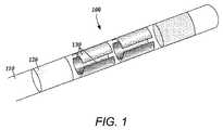
図1に、脳刺激用リード100の1つの実施形態を示す。この装置は、リード本体110、1又はそれ以上の任意のリング電極120、及び複数の分割電極130を含む。リード本体110は、例えばポリマー材料などの生体適合性の非導電材料で形成することができる。好適なポリマー材料として、以下に限定されるわけではないが、シリコン、ポリウレタン、ポリエチレン、ポリウレア、又はポリウレタンウレアが挙げられる。少なくともいくつかの例では、リードが長時間にわたって体組織と接触することができる。少なくともいくつかの実施形態では、リードの断面直径が1.5mm以下であり、少なくともいくつかの実施形態では1mm〜1.5mmとすることができ、リードの長さは少なくとも10cmであり、25cm〜70cmとすることもできる。 FIG. 1 illustrates one embodiment of a
少なくともいくつかの実施形態では、リード本体110上に刺激電極を配置することができる。これらの刺激電極は、金属、合金、導電性酸化物、又はその他のあらゆる好適な導電性の生体適合性材料を使用して作成することができる。好適な材料の例として、以下に限定されるわけではないが、プラチナ、プラチナイリジウム合金、イリジウム、チタン、又はタングステンが挙げられる。刺激電極は、生体適合性であるとともに、予想される動作環境での動作条件下で予想される使用期間にわたって実質的に腐食しない材料で作成されることが好ましい。 In at least some embodiments, a stimulation electrode can be disposed on the
少なくともいくつかの実施形態では、これらの電極をいずれも陽極又は陰極として使用することができ、陽極又は陰極電流を流すことができる。いくつかの例では、電極をある期間にわたって陽極とし、ある期間にわたって陰極とすることができる。他の実施形態では、特定の1又は複数の電極を陽極又は陰極として固定的に識別することができる。 In at least some embodiments, any of these electrodes can be used as an anode or cathode, and an anode or cathode current can flow. In some examples, the electrode can be an anode for a period of time and a cathode for a period of time. In other embodiments, a particular electrode or electrodes can be fixedly identified as an anode or a cathode.
リング電極120の形の刺激電極は、リード本体110のあらゆる部分に、通常はリードの遠位端近くに配置することができる。図1には、2つのリング電極を有するリードの一部を示している。リード本体110の長さに沿ってあらゆる数のリング電極を配置することができ、又はリング電極を1つだけ配置することもできる。例えば、リード本体は、1つのリング電極、2つのリング電極、3つのリング電極又は4つのリング電極を有することができる。いくつかの実施形態では、リードが、5つ、6つ、7つ又は8つのリング電極を有する。リード本体110の長さに沿ってあらゆる数のリング電極を配置できることが理解されるであろう。いくつかの実施形態では、リング電極120が実質的に円筒形であり、リード本体110の外周全体を包む。いくつかの実施形態では、リング電極120の外径が、実質的にリード本体110の外径に等しい。リング電極120の幅は、標的ニューロンの所望の処置及び場所によって異なることができる。いくつかの実施形態では、リング電極120の幅が、リング電極120の直径以下である。他の実施形態では、リング電極120の幅が、リング電極120の直径よりも大きい。 A stimulation electrode in the form of a
脳深部刺激での標的構造は、遠位電極アレイの軸を中心に対称でないので、分割電極を有する脳深部刺激リードは優れた電流ステアリングを提供する。代わりに、リードの軸を通る平面の片側に標的を位置付けることもできる。径方向分割電極アレイ(RSEA)の使用を通じ、電流ステアリングをリードの軸に沿って、ただしリードの外周の周囲で行うこともできる。 Since the target structure for deep brain stimulation is not symmetric about the axis of the distal electrode array, a deep brain stimulation lead with split electrodes provides excellent current steering. Alternatively, the target can be positioned on one side of a plane passing through the lead axis. Through the use of a radial segmented electrode array (RSEA), current steering can also be performed along the lead axis, but around the periphery of the lead.
リードは、複数の分割電極130を含む。リード本体110上には、あらゆる数の分割電極130を配置することができる。いくつかの実施形態では、分割電極130が分割電極の組にグループ化され、各組がリードの外周の周囲の特定の長手方向位置に配置される。リードは、あらゆる数の分割電極の組を有することができる。少なくともいくつかの実施形態では、リードが、1つ、2つ、3つ、4つ、5つ、6つ、7つ、又は8つの分割電極の組を有する。少なくともいくつかの実施形態では、各分割電極の組が同じ数の分割電極130を含む。いくつかの実施形態では、各分割電極の組が3つの分割電極130を含む。少なくとも他のいくつかの実施形態では、各分割電極の組が、2つ、4つ、5つ、6つ、7つ又は8つの分割電極を含む。分割電極130は、サイズ及び形状が異なってもよい。いくつかの実施形態では、分割電極130が、全て同じサイズ、形状、直径、幅又は面積、又はこれらのいずれかの組み合わせのものである。いくつかの実施形態では、各組の分割電極(さらには全ての分割電極)のサイズ及び形状を同じにすることができる。 The lead includes a plurality of divided
各分割電極130の組をリード本体110の外周の周囲に配置して、リード本体110を取り巻いて実質的に円筒形を形成することができる。図7B、図8B及び図9Bを参照しながら説明するように、リード本体110の外周を取り巻く分割電極130の間隔は異なってもよい。少なくともいくつかの実施形態では、リード本体110の外周を取り巻く各分割電極130間に、等しい空間、隙間又は切り欠きが置かれる。他の実施形態では、分割電極間の空間、隙間又は切り欠きのサイズ又は形状が異なることができる。他の実施形態では、特定の分割電極の組又は全ての分割電極の組に関して、分割電極間の空間、隙間又は切り欠きを均一にすることができる。分割電極130は、リード本体110の周囲に不規則な又は規則的な間隔で配置することができる。 A set of each divided
リング電極120及び分割電極130に結合する又はこれらから生じる導体(図示せず)もリード本体110内を通る。これらの導体は、リードの材料、又はリードにより形成される管腔を通ることができる。これらの導体は、電極を制御ユニット(図示せず)に結合するためのコネクタに存在する。1つの実施形態では、刺激電極が、リード本体110から延びるワイヤ導体に対応し、この結果リード表面と同じ高さに研削又は研磨される。これらの導体を制御ユニットに結合して、多くの場合パルスの形の刺激信号を刺激電極に供給することができる。 A conductor (not shown) coupled to or resulting from the
図2は、複数の分割電極を有するリードの別の実施形態の概略側面図である。図2で分かるように、複数の分割電極130を相対的に異なる配向で配置することができる。リード本体110の長さに沿って2つの分割電極の組が整列している図1とは異なり、図2には、2つの分割電極130の組が互い違いになった別の実施形態を示している。少なくともいくつかの実施形態では、分割電極の組が、リード本体110の長さに沿って整列した分割電極が存在しないように互い違いになる。いくつかの実施形態では、分割電極を、分割電極の少なくとも1つが異なる組の別の分割電極と整列し、他の分割電極が整列しないように互い違いにすることができる。 FIG. 2 is a schematic side view of another embodiment of a lead having a plurality of segmented electrodes. As can be seen in FIG. 2, the plurality of
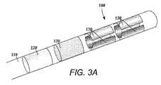
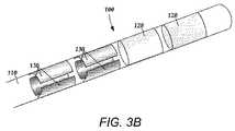
リード本体110上には、あらゆる数の分割電極130をあらゆる数の組で配置することができる。図1及び図2には、2つの分割電極の組を含む実施形態を示している。これらの2つの分割電極130の組を異なる構成で配置することができる。図3は、複数の分割電極を有するリードの第3の実施形態の概略斜視図である。図3Aのリード本体110は、近位端及び遠位端を有する。図3Aから分かるように、2つの分割電極130の組が、リード本体110の遠位端上の2つのリング電極120の遠位に配置されている。図3Bは、リード本体110の第4の実施形態の概略斜視図である。図3Bでは、2つの分割電極130の組が、2つのリング電極120の近位に配置されている。分割電極130の場所を変えることにより、異なる標的ニューロンの範囲を選択することができる。例えば、神経標的がリード本体110の遠位端の方に近くなると医師が予想する場合には、図3Aの電極配列を有用とすることができ、神経標的がリード本体110の近位端の方に近くなると医師が予想する場合には、図3Bの電極配列を有用とすることができる。少なくともいくつかの実施形態では、リング電極120が分割電極130の組と交互になる。 Any number of divided
リード上には、リング電極120と分割電極130のあらゆる組み合わせを配置することができる。いくつかの実施形態では、分割電極が組で配置される。例えば、リードが、第1のリング電極120、各々が3つの分割電極130で形成された2つの分割電極の組、及びリードの端部に最後のリング電極120を含むことができる。この構成は、単純に1−3−3−1構成と呼ぶことができる。この簡単明瞭な表記法で電極を呼ぶことは好都合である。従って、図3Aの実施形態は1−1−3−3構成と呼ぶことができ、一方で図3Bの実施形態は3−3−1−1構成と呼ぶことができる。他の8電極構成には、例えば、4つの分割電極の組をリード上に配置した2−2−2−2構成、及び各々が4つの分割電極130を有する2つの分割電極の組をリード上に配置した4−4構成がある。いくつかの実施形態では、リードが16個の電極を有する。16電極リードで考えられる構成には、以下に限定されるわけではないが、4−4−4−4、8−8、3−3−3−3−3−1(及びこの構成の全ての再配置)、及び2−2−2−2−2−2−2−2がある。 Any combination of the
図4は、リードの長さに沿った様々な電極レベルに従う径方向電流ステアリングを示す概略図である。従来のリング電極を有するリード構成では、電流をリードの長さ(z軸)に沿って導くことしかできないが、分割電極構成では、電流をx軸、y軸及びz軸に導くことができる。従って、リード本体110を取り囲む3次元空間内のあらゆる方向に刺激の重心を導くことができる。いくつかの実施形態では、以下でより詳細に説明するように、(刺激はその大部分が陰極近くで生じるが、強力な陽極が刺激を引き起こすこともあると認識すれば)各電極に導入される陽極電流の割合が、リード本体110の外周の周囲の径方向距離r及び角度θを左右することができる。少なくともいくつかの実施形態では、分割電極130に沿った陽極及び陰極の構成により、刺激の重心がリード本体110に沿って様々な異なる場所に偏移できるようになる。 FIG. 4 is a schematic diagram showing radial current steering according to various electrode levels along the length of the lead. In a lead configuration having a conventional ring electrode, current can only be guided along the length of the lead (z axis), whereas in a split electrode configuration, current can be guided in the x, y and z axes. Therefore, the center of gravity of the stimulus can be guided in all directions within the three-dimensional space surrounding the
図4から分かるように、刺激の重心をリードの長さに沿って各レベルで偏移させることができる。リードの長さに沿った異なるレベルの複数の分割電極130の組を使用すると、3次元電流ステアリングが可能になる。いくつかの実施形態では、分割電極130の組が集合的に偏移する(すなわち、刺激の重心がリードの長さに沿って各レベルで類似する)。少なくとも他のいくつかの実施形態では、個々の分割電極130の組が独立して制御される。個々の分割電極の組は、2つ、3つ、4つ、5つ、6つ、7つ、8つ又はそれ以上の分割電極を含むことができる。各レベルの分割電極の数を変えることにより、異なる刺激プロファイルを生み出すことができると理解できよう。例えば、個々の分割電極の組が2つの分割電極しか含まない場合、刺激プロファイル内に均一に分散した(選択的に刺激ができない)隙間を形成することができる。いくつかの実施形態では、少なくとも3つの分割電極130を利用して、選択的に真の360°を可能にする。 As can be seen from FIG. 4, the center of gravity of the stimulus can be shifted at each level along the length of the lead. Using a set of
前述したように、上述の構成を使用しながら記録電極を利用することもできる。いくつかの実施形態では、制御ユニット又はマイクロドライブモータシステムに、標的ニューロンにより刺激される筋肉又はその他の組織に結合された測定装置、又は患者又は臨床医に応答するユニットを結合することができる。測定装置、ユーザ、又は臨床医は、刺激電極又は記録電極に対する標的筋肉又はその他の組織による反応を示して、標的ニューロンをさらに識別し、刺激電極の位置決めを容易にすることができる。例えば、標的ニューロンが、振戦を生じる筋肉を対象としている場合、測定装置を使用して筋肉を観察し、ニューロンの刺激に反応する振戦の周期又は振幅の変化を示すことができる。或いは、患者又は臨床医が筋肉を観察してフィードバックを行うこともできる。 As described above, the recording electrode can be used while using the above-described configuration. In some embodiments, the control unit or microdrive motor system can be coupled to a measurement device coupled to muscle or other tissue stimulated by the target neuron or a unit responsive to the patient or clinician. A measurement device, user, or clinician can indicate a response by the target muscle or other tissue to the stimulation or recording electrode to further identify the target neuron and facilitate positioning of the stimulation electrode. For example, if the target neuron is intended for muscles that cause tremors, the measuring device can be used to observe the muscles and indicate changes in tremor period or amplitude in response to neuronal stimulation. Alternatively, the patient or clinician can observe the muscle and provide feedback.
リードの信頼性及び耐久性は、設計及び製造方法に大きく依存する。以下で説明する製造技術は、リードの破損件率が非常に低いことを実証したリードの製造方法を示すものである。 Lead reliability and durability are highly dependent on design and manufacturing methods. The manufacturing technology described below demonstrates a lead manufacturing method that demonstrates a very low lead failure rate.
いくつかの実施形態では、リードの製造が近位端から開始される。図5は、リード本体510の遠位端で露出されたリード導体540を有するリード500の一部の斜視図である。図1を参照しながら上述したように、導体540は、予備電極600に結合し又はこれらから生じ、リード本体510も通過する。これらの導体は、リードの材料、又はリードにより形成される管腔を通ることができる。いくつかの実施形態では、刺激電極又は記録電極が、リード本体510から延びるワイヤ導体に対応し、この結果リード表面と同じ高さに研削又は研磨される。導体540を、さらに端子(図示せず)に結合することもできる。通常、これらの端子は、例えば制御モジュール上に配置されたコネクタ内の対応するコネクタ接点に(又はリード延長部、手術室ケーブル、又はアダプタ上のコネクタ接点などのその他の装置に)接続するために、1又はそれ以上のリード本体の近位端に配置される。さらに、制御モジュールは、多くの場合パルスの形の刺激信号を刺激電極に供給することができる。リード本体510及び遠位端で露出される導体540の長さは、最終的な製品構成に合わせて必要に応じて変更することができる。 In some embodiments, lead manufacture begins at the proximal end. FIG. 5 is a perspective view of a portion of a lead 500 having a lead conductor 540 exposed at the distal end of the lead body 510. As described above with reference to FIG. 1, the conductor 540 couples to or originates from the
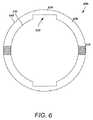
いくつかの実施形態では、径方向分割電極アレイの製造が予備電極から開始し、この予備電極から分割電極が形成される。図6は、予備電極600の概略断面図である。図6で分かるように、いくつかの実施形態では、予備電極600が、2つの厚壁部分620によって分離された2つの薄壁部分610を有する。薄壁部分610及び厚壁部分620は、内径630及び外径640を作成することにより形成することができる。いくつかの実施形態では、外径640は等直径であるが、内径630は等直径でない。代わりに、内径630は、内径が残りの部分よりも大きな、或いは予備電極600の一部が除去された又は形成されていない鍵状部分635を含む不規則な直径を有することができる。図6で分かるように、この鍵状部分635は、直径が突然変化した結果、又は直径が次第に変化した結果とすることができる。 In some embodiments, the production of the radially divided electrode array begins with a spare electrode from which the divided electrode is formed. FIG. 6 is a schematic sectional view of the
結果として得られる薄壁部分610と厚壁部分620は、サイズが異なることができる。いくつかの実施形態では、薄壁部分610と厚壁部分620の径方向サイズが等しい。少なくとも他のいくつかの実施形態では、予備電極600の外周の大部分が厚壁部分620を形成する。図6で分かるように、いくつかの実施形態では、2つの厚壁部分及び2つの薄壁部分が形成される。いくつかの実施形態では、薄壁部分610の径方向サイズが等しい。いくつかの実施形態では、厚壁部分620の径方向サイズが等しい。少なくとも他のいくつかの実施形態では、1つの厚壁部分を別の厚壁部分よりも大きく形成することができると理解できよう。 The resulting
いくつかの実施形態では、図5のリード本体510が、図6の予備電極600を受け入れるための切除部分を含む。いくつかの実施形態では、リード本体510の遠位端の、特にリード本体510の予備電極600の下部に配置される部分にリード本体の切除部分が配置される。いくつかの実施形態では、予備電極600の特に内径に、スロット、グリット、サンドブラスト加工した又は粗面化した領域、或いは窒化チタンなどの皮膜を付加して、リード本体510への接着力を増加させる。その後、予備電極600に導体を結合することができる。いくつかの実施形態では、導体が予備電極600に溶接されるが、レーザ溶接、抵抗溶接、及び導電性エポキシ樹脂などの、予備電極を導体に結合するあらゆる好適な方法を利用できることが理解できよう。図6で分かるように、予備電極600は、導体及び溶接を位置付けるための溝付き位置650を含むことができる。いくつかの実施形態では、予備電極600の各部分が導体に接続されるように、予備電極600上に複数の溝付き位置を配置することができる。図6で分かるように、少なくともいくつかの実施形態では、溝付き位置650が予備電極600の両側に配置される。 In some embodiments, the lead body 510 of FIG. 5 includes a cut-out portion for receiving the
いくつかの実施形態では、リード本体510の長さに沿って、個々の予備電極600の隣にスペーサ520が配置される。これらのスペーサ520を予備電極600間に配置することができ、またこれらのスペーサ520は、スペーサ520をリード本体510上に螺入して、又はリード本体510の一部として使用して電極を分離できるように空洞の中心領域を有することができる。リード500は、端部スペーサ(図示せず)を含むこともできる。端部スペーサは、リード500の遠位端に配置される。端部スペーサは、いずれの形状であってもよいが、遠位端で丸くなることが好ましい。スペーサ520及び端部スペーサは、例えば、シリコン、ポリウレタン、及びポリエーテルエーテルケトン(PEEK)を含むあらゆる非導電性の生体適合性材料で作成することができる。スペーサ520は、予備電極600を電気的に絶縁する役に立つ。これに加えて、又はこれの代わりに、リード本体510を貫く開口部と隣接する非導電性リード本体510の部分上に予備電極を配置して、導体540が予備電極600に結合できるようにすることができる。 In some embodiments, spacers 520 are disposed along the length of the lead body 510 next to each
いくつかの実施形態では、予備電極600の外径をスペーサの外径と同じにすることができる。いくつかの実施形態では、予備電極600の外径を別様にスペーサ520の外径よりも大きくして、予備電極600がスペーサ520よりも高くなるようにすることができる。或いは、スペーサ520の外径を予備電極600の外径よりも大きくして、予備電極が引っ込むようにすることができる。 In some embodiments, the outer diameter of the
全てのスペーサ520及び予備電極600をリード本体510上に装着した後に、アセンブリにリフロー作業を行うことができる。リフロー作業は、スペーサ500及び予備電極600をリード本体510に取り付ける上で有用であり、アセンブリの構造的完全性を改善して信頼性を向上させる。 After all the spacers 520 and the
その後、リード500をさらに処理して予備電極600の一部を除去することができる。いくつかの実施形態では、リード500を心なし研削して、外径640の一部(例えば、薄壁部分610)を除去するが、切断、スカイビング又はレーザアブレーションを含むあらゆる好適な方法を使用して、これらの部分を除去できると理解されるであろう。図7は、図6の予備電極600の薄壁部分610を除去した後の概略断面図である。図7で分かるように、薄壁部分を除去した結果、2つの分割電極700が形成される。従って、薄壁部分610及び厚壁部分620は、研削後に分割電極700のあらゆる構成が形成されるように構成することができる。溝付き位置650も、研削処理後に各分割電極700が導体に接続されるように構成できると理解されよう。 Thereafter, the
図8は、3つの厚壁部分820によって分離された3つの薄壁部分810を有する予備電極800の概略断面図である。予備電極800は、内径830及び外径840を有する。図8で分かるように、内径には3つの鍵状部分835がある。図9で分かるように、上述の方法を使用して薄壁部分を除去すると、図8の予備電極800は、3つの分割電極900を形成することができる。いくつかの実施形態では、3つの分割電極900のサイズが同じである。少なくとも他のいくつかの実施形態では、鍵状部分835が、研削処理後に異なるサイズの分割電極900が作成されるように構成される。さらに、この鍵状部分を、各分割電極が導体に接続するための溝付き位置850を含むように構成することができる。この方法であらゆる数の分割電極を形成できることが理解されよう。例えば、これらの方法を使用して、4個、5個、6個、7個、8個、10個、12個、又は16個の径方向に配列した分割電極を有するリードを作成することができる。 FIG. 8 is a schematic cross-sectional view of a
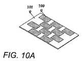
少なくとも他のいくつかの実施形態では、径方向分割電極アレイの形成がプレートから開始する。図10Aは、プレート1010に結合された複数の電極1000の概略斜視図である。抵抗溶接、レーザ溶接、又は接着剤などのあらゆる好適な方法を使用して、複数の電極1000をプレート1010に結合することができる。いくつかの実施形態では、プレート1010が鉄板であるが、支持構造として機能し、上述したいずれの処理(例えば、選択的エッチング処理)によっても除去できるあらゆる好適な金属を使用することができる。 In at least some other embodiments, formation of the radially divided electrode array begins with a plate. FIG. 10A is a schematic perspective view of a plurality of electrodes 1000 coupled to plate 1010. Any suitable method such as resistance welding, laser welding, or adhesive can be used to couple the plurality of electrodes 1000 to the plate 1010. In some embodiments, plate 1010 is a steel plate, but any suitable metal that functions as a support structure and can be removed by any of the processes described above (eg, a selective etching process) can be used.
複数の電極1000を、いずれかの望ましい配列でプレート1010上に配置することができる。例えば、いくつかの実施形態では、複数の電極1000を、プレート1010上で等間隔の列に分割する。各列は、同じ数の又は異なる数の電極を含むことができる。いくつかの実施形態では、これらの列が異なる数の電極を含む。電極が長手方向に整列しないように、列を互いにずらすこともできる。列内で又は列間で、電極間の間隔を変えることもできる。少なくとも他のいくつかの実施形態では、複数の電極1000が、プレート1010上に、円形配列、傾斜配列、又はその他のいずれかの所望のパターンで配置される。 The plurality of electrodes 1000 can be disposed on the plate 1010 in any desired arrangement. For example, in some embodiments, the plurality of electrodes 1000 are divided into equally spaced rows on the plate 1010. Each column can include the same or different number of electrodes. In some embodiments, these columns include a different number of electrodes. The columns can also be offset from one another so that the electrodes are not aligned in the longitudinal direction. It is also possible to vary the spacing between the electrodes within a row or between rows. In at least some other embodiments, the plurality of electrodes 1000 are arranged on the plate 1010 in a circular array, a tilted array, or any other desired pattern.
その後、この複数の電極1000に、溶接又はその他の技術によって導体(図示せず)を接合する。いくつかの実施形態では、各個々の電極が、別個の及び異なる導体に接続される。少なくとも他のいくつかの実施形態では、複数の電極が同じ導体に接続される。 Thereafter, a conductor (not shown) is joined to the plurality of electrodes 1000 by welding or other techniques. In some embodiments, each individual electrode is connected to a separate and different conductor. In at least some other embodiments, multiple electrodes are connected to the same conductor.
いくつかの実施形態では、その後プレート1010を円筒に形成する。いくつかの実施形態では、円筒を形成するために、プレート1010の中央線に沿ってマンドレルを配置し、これを近位端のサブアセンブリのリード本体の中心管腔に挿入する。次に、1つの又は一連の金型を通じてプレート1010を引き出して所望の円筒形を形成することができる。この円筒は、複数の電極1000に取り付けられたままの導体が円筒の中心管腔を貫いて延びるように形成することができる。図10Bは、プレート1010に結合した複数の電極1000の、プレート1010を円筒1020に形成した後の概略斜視図である。 In some embodiments, the plate 1010 is then formed into a cylinder. In some embodiments, to form a cylinder, a mandrel is placed along the centerline of the plate 1010 and inserted into the central lumen of the lead body of the proximal end subassembly. The plate 1010 can then be pulled through one or a series of molds to form the desired cylindrical shape. The cylinder may be formed such that a conductor that remains attached to the plurality of electrodes 1000 extends through the central lumen of the cylinder. FIG. 10B is a schematic perspective view of the plurality of electrodes 1000 coupled to the plate 1010 after the plate 1010 is formed in the
新たに形成された円筒1020は、導体が中を貫いて延びる中空の中心管腔を含む。この円筒1020の中心管腔を絶縁又はポリマー材料で満たして、リード本体1030を作成することができる。上述したように、好適なポリマー材料としては、以下に限定されるわけではないが、シリコン、ポリウレタン、及びポリエチレンが挙げられる。図10Cは、図10Bの円筒の管腔を絶縁材料で満たしてリードアセンブリ1040を作成した後の概略斜視図である。いくつかの実施形態では、円筒1020に液状シリコンゴムを注入してリード本体1030を形成する。 The newly formed
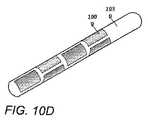
円筒1020に絶縁材料を注入してリードアセンブリ1040を形成した後、このリードアセンブリ1040に、これを硬化させるための一連のステップを施すことができる。その後、リードアセンブリ1040からプレート1010を除去して複数の電極1000を露出させる。いくつかの実施形態では、リードアセンブリ1040を酸浴に入れてプレート1010を溶解させる。或いは、あらゆる好適な技術を使用して、リードアセンブリ1040からプレート1010を除去することができる。図10Dは、図10Cの円筒のプレート1010を除去した後の概略斜視図である。リードアセンブリ1040は、複数の電極1000をプレート1010に溶接するために選択した配列に対応する径方向配列の複数の電極1000を含む。 After injecting insulating material into the
いくつかの実施形態では、様々な材料を使用してリードが形成されると理解できよう。例えば、円筒1020に注入する材料は、リードの残りの部分にわたって使用する材料と同じものである必要はない。リードを構築する材料は、例えば、生体適合性、(可撓性、引張強度、引裂強度、及び伸びなどの)機械的特性、生物学的安定性、取扱特性、製造の容易さ、コスト、及び製造時間などを含む様々な因子に依存して選択することができる。従って、リードの異なる部品に沿って異なる材料を使用してリードを作成することができる。例えば、シリコン又はポリウレタンなどの1つの材料で遠位端を形成し、ポリウレタン又はPEEKなどの別の材料を使用してリードの近位端を形成することができる。一例として、リードの遠位端には、可撓性の高い材料という理由でシリコンを選択することができる。近位端には、剛性が高く、(埋め込み式パルス発生器などの)制御モジュール又はリードコネクタへの挿入を改善する高い剛性を与えるという理由でポリウレタンを選択することができる。これらのリードでは、異なる材料で形成されたリードの2つの部分が遷移部位で連結する。一般に、遷移部位とは、リードの長さに沿った近位端と遠位端の間のあらゆる好適な部位とすることができる。遷移部位は、リードの2つの部分を同じ材料で形成し、後でともに接合した場合にも生じ得る。遷移部位は、リードに沿ったあらゆる地点に位置することができ、リードは、複数の遷移部位を含むことができると認識されよう。 It will be appreciated that in some embodiments, leads are formed using a variety of materials. For example, the material injected into the
いくつかの実施形態では、遷移部位を覆うスリーブを使用して、リードの2つの部分をともに結合する。しかしながら、遷移部位におけるリードの直径がスリーブによって増加することがあり、このことは、特に遷移部位におけるリードの大きな直径には大きな直径のイントロデューサを対応させる必要が生じ得るので望ましくない場合がある。 In some embodiments, a sleeve covering the transition site is used to join the two portions of the lead together. However, the diameter of the lead at the transition site may be increased by the sleeve, which may not be desirable, especially because the large diameter of the lead at the transition site may need to accommodate a large diameter introducer.
少なくとも他のいくつかの実施形態では、スリーブの代わりに、接続構成を形成する部分の端部を修正することにより、遷移部位におけるリードの2つの部分を結合することができる。リードは、円筒1020に注入される第1の材料で作成された第1のリード部分と、第2の材料で作成された第2のリード部分とを含む。例えば、第1の材料をシリコン、第2の材料をポリウレタンとすることができ、これらは逆であってもよい。第1のリード部分は、リードの遠位部分又は近位部分のいずれであってもよく、このときリードの第2の部分は、それぞれリードの近位部分又は遠位部分であることが認識されよう。 In at least some other embodiments, instead of the sleeve, the two portions of the lead at the transition site can be joined by modifying the end of the portion forming the connection configuration. The lead includes a first lead portion made of a first material injected into the
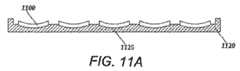
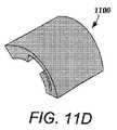
図11Dは、液状射出成形を使用してキャリア内にモールド成形することができる電極1100の1つの実施形態の概略斜視図である。この処理について、図11A〜図11Cを参照しながらより詳細に説明する。図11Aで分かるように、電極1100をキャリアモールド1120内に位置付けることにより、電極1100を所望のアレイ配列で設置することができる。いくつかの実施形態では、図11A〜図11Dで分かるように、電極1100が湾曲している。少なくとも他のいくつかの実施形態では、電極1100が、キャリアモールド内に配置するときは平坦であり、後で所望の形状に形成される。キャリアモールド1120に適した材料として、以下に限定されるわけではないが、金属、ポリマー(プラスチックを含む)、及び複合材料などが挙げられる。キャリアモールド1120は、キャリアモールド1120の再利用を可能にする耐久性の高い材料で作成されることが好ましい。いくつかの実施形態では、キャリアモールド1120が湾曲し、又は円筒状である。電極1100は、あらゆる好適な配列でキャリアモールド内に配置することができる。例えば、キャリアモールド1120内に電極1100を2列、3列、又は4列で配置することができ、各列はあらゆる数の電極を含むことができる。キャリアをマンドレルの周囲に巻き付けることができるので、図1で分かるように、キャリアモールド1120内に配置された電極1100の列は、円周方向の電極配列と一致することができる。 FIG. 11D is a schematic perspective view of one embodiment of an
キャリアモールド1120は、キャリアモールド1120内の所望のアレイ配列で配置された窪み又は凹部などの電極配置用特徴部1125を含むことができる。電極配置用特徴部1125は、電極1100を予め設定した配列で位置付ける役に立つ。例えば、キャリアの製造工程中に電極1100の形状に対応してこれを適所に保持する窪みを底部に有するキャリアモールド1120内に電極1100を配置することができる。電極1100は凹形とすることができ、キャリアモールド1120は、電極1100の凹形状に対応する窪みを有することができる。電極1100の側面の少なくとも一部は、キャリアモールド1120内に露出されたままであることが好ましい。 The
図11Bから分かるように、電極1100をキャリアモールド1120内に配置した後に、電極1100及びキャリアモールド1120を覆ってキャリアモールドカバー1130を配置することができる。キャリアモールドカバー1130に適した材料としては、以下に限定されるわけではないが、金属、ポリマー(プラスチックを含む)、及び複合材料などが挙げられる。キャリアモールドカバー1130は、キャリアモールドカバー1130の再利用を可能にする金属などの耐久性材料で作成されることが好ましい。 As can be seen from FIG. 11B, after the
図11Cは、図11Bのアセンブリの電極1110のアレイの周囲にキャリア1140をモールド成形した後の概略断面図である。キャリア1140は、例えば、シリコン、ポリウレタン、ポリエーテルエーテルケトン(PEEK)、及びエポキシ樹脂などを含むあらゆる生体適合性材料で作成することができる。 FIG. 11C is a schematic cross-sectional view after the
キャリア1140は、例えば、モールド成形(射出成形を含む)、及び鋳造などを含むあらゆる処理によって形成することができる。いくつかの実施形態では、キャリア1140が射出成形によって形成される。キャリア1140を電極1100の周囲にモールド成形した後、キャリア1140内に位置する電極1100に導体(図示せず)を接合する。任意に、電極1100に導体を結合する前に、完成したキャリア及び電極1100のアレイを含む中間アセンブリをキャリアモールド1120から除去することができる。次に、溶接ケーブルを有するキャリア1140をマンドレルの周囲に巻き付けて実質的に円筒の形を作成し、オーバーモールド内に配置する。その後、アセンブリをオーバーモールド成形して、径方向分割電極アレイを形成する。 The
上記明細書、実施例及びデータは、本発明の組成の製造及び用途を説明するものである。本発明の思想及び範囲から逸脱することなく、本発明の多くの実施形態を構成できるので、本発明は、以下に添付する特許請求の範囲にも帰する。 The above specification, examples and data illustrate the manufacture and use of the composition of the invention. Since many embodiments of the invention can be made without departing from the spirit and scope of the invention, the invention resides in the claims hereinafter appended.
100 リード
110 リード本体
120 リング電極
130 分割電極100
Claims (8)
Translated fromJapanese少なくとも2つの厚壁部分により分離された少なくとも2つの薄壁部分を含む少なくとも1つのリング形状の予備電極を形成するステップを含み、前記リングの外径は、等直径であり、
さらに、前記少なくとも1つの予備電極をリード本体の遠位端近くに配置するステップと、
前記少なくとも1つの予備電極の各厚壁部分に少なくとも1つの導体を接合するステップと、
前記リード本体及び前記少なくとも1つの予備電極を研削して前記少なくとも1つの予備電極の前記薄壁部分を除去し、前記少なくとも1つの予備電極の前記厚壁部分から複数の分割電極を形成するステップと、
を含むことを特徴とする方法。A method of creating a lead for a stimulator,
Forming at least one ring-shaped preelectrode comprising at least two thin wall portions separated by at least two thick wall portions, wherein the outer diameter of the ring is equal;
Further, disposing the at least one spare electrode near the distal end of the lead body;
Bonding at least one conductor to each thick wall portion of the at least one preliminary electrode;
Grinding the lead body and the at least one reserve electrode to remove the thin wall portion of the at least one reserve electrode and forming a plurality of split electrodes from the thick wall portion of the at least one reserve electrode; ,
A method comprising the steps of:
Applications Claiming Priority (3)
| Application Number | Priority Date | Filing Date | Title |
|---|---|---|---|
| US12/498,650 | 2009-07-07 | ||
| US12/498,650US8887387B2 (en) | 2009-07-07 | 2009-07-07 | Methods of manufacture of leads with a radially segmented electrode array |
| PCT/US2010/040995WO2011005716A2 (en) | 2009-07-07 | 2010-07-02 | Systems and leads with a radially segmented electrode array and methods of manufacture |
Publications (2)
| Publication Number | Publication Date |
|---|---|
| JP2012532674A JP2012532674A (en) | 2012-12-20 |
| JP5612090B2true JP5612090B2 (en) | 2014-10-22 |
Family
ID=42782034
Family Applications (1)
| Application Number | Title | Priority Date | Filing Date |
|---|---|---|---|
| JP2012519636AExpired - Fee RelatedJP5612090B2 (en) | 2009-07-07 | 2010-07-02 | How to create a lead for a stimulator |
Country Status (8)
| Country | Link |
|---|---|
| US (3) | US8887387B2 (en) |
| EP (1) | EP2451524B1 (en) |
| JP (1) | JP5612090B2 (en) |
| CN (1) | CN102665818B (en) |
| AU (1) | AU2010270762B2 (en) |
| CA (1) | CA2767248A1 (en) |
| ES (1) | ES2535647T3 (en) |
| WO (1) | WO2011005716A2 (en) |
Families Citing this family (199)
| Publication number | Priority date | Publication date | Assignee | Title |
|---|---|---|---|---|
| US7860570B2 (en) | 2002-06-20 | 2010-12-28 | Boston Scientific Neuromodulation Corporation | Implantable microstimulators and methods for unidirectional propagation of action potentials |
| US7583999B2 (en) | 2006-07-31 | 2009-09-01 | Cranial Medical Systems, Inc. | Multi-channel connector for brain stimulation system |
| US8321025B2 (en) | 2006-07-31 | 2012-11-27 | Cranial Medical Systems, Inc. | Lead and methods for brain monitoring and modulation |
| WO2008115426A1 (en) | 2007-03-19 | 2008-09-25 | Boston Scientific Neuromodulation Corporation | Mri and rf compatible leads and related methods of operating and fabricating leads |
| ES2605170T3 (en) | 2007-03-19 | 2017-03-13 | Boston Scientific Neuromodulation Corporation | Cable manufacturing procedures and apparatus with conductors and related flexible cable configurations |
| US8359107B2 (en) | 2008-10-09 | 2013-01-22 | Boston Scientific Neuromodulation Corporation | Electrode design for leads of implantable electric stimulation systems and methods of making and using |
| AU2010236196B2 (en) | 2009-04-16 | 2015-11-12 | Boston Scientific Neuromodulation Corporation | Deep brain stimulation current steering with split electrodes |
| US8875391B2 (en) | 2009-07-07 | 2014-11-04 | Boston Scientific Neuromodulation Corporation | Methods for making leads with radially-aligned segmented electrodes for electrical stimulation systems |
| US8887387B2 (en) | 2009-07-07 | 2014-11-18 | Boston Scientific Neuromodulation Corporation | Methods of manufacture of leads with a radially segmented electrode array |
| US8295944B2 (en) | 2009-11-30 | 2012-10-23 | Boston Scientific Neuromodulation Corporation | Electrode array with electrodes having cutout portions and methods of making the same |
| US8391985B2 (en)* | 2009-11-30 | 2013-03-05 | Boston Scientific Neuromodulation Corporation | Electrode array having concentric windowed cylinder electrodes and methods of making the same |
| US8788063B2 (en) | 2009-11-30 | 2014-07-22 | Boston Scientific Neuromodulation Corporation | Electrode array having a rail system and methods of manufacturing the same |
| US8874232B2 (en) | 2009-11-30 | 2014-10-28 | Boston Scientific Neuromodulation Corporation | Electrode array having concentric split ring electrodes and methods of making the same |
| US8571665B2 (en)* | 2010-03-23 | 2013-10-29 | Boston Scientific Neuromodulation Corporation | Helical radial spacing of contacts on a cylindrical lead |
| EP2582425B1 (en) | 2010-06-18 | 2018-04-04 | Boston Scientific Neuromodulation Corporation | Method of making electrode array having embedded electrodes |
| US9675795B2 (en) | 2010-07-16 | 2017-06-13 | Boston Scientific Neuromodulation Corporation | Systems and methods for radial steering of electrode arrays |
| US8583237B2 (en) | 2010-09-13 | 2013-11-12 | Cranial Medical Systems, Inc. | Devices and methods for tissue modulation and monitoring |
| AU2011305914B2 (en) | 2010-09-21 | 2016-05-12 | Boston Scientific Neuromodulation Corporation | Systems and methods for making and using radially-aligned segmented electrodes for leads of electrical stimulation systems |
| CA2822343A1 (en) | 2010-12-23 | 2012-06-28 | Boston Scientific Neuromodulation Corporation | Methods for making leads with segmented electrodes for electrical stimulation systems |
| US8700179B2 (en) | 2011-02-02 | 2014-04-15 | Boston Scientific Neuromodulation Corporation | Leads with spiral of helical segmented electrode arrays and methods of making and using the leads |
| US20120203316A1 (en) | 2011-02-08 | 2012-08-09 | Boston Scientific Neuromodulation Corporation | Leads with segmented electrodes for electrical stimulation of planar regions and methods of making and using |
| JP2014511227A (en) | 2011-02-08 | 2014-05-15 | ボストン サイエンティフィック ニューロモデュレイション コーポレイション | Method of manufacturing a lead having segmented electrodes for an electrical stimulation system |
| ES2801326T3 (en) | 2011-02-08 | 2021-01-11 | Boston Scient Neuromodulation Corp | Spirally arranged lead wires with segmented electrodes and lead wire manufacturing and use procedures |
| US20120221084A1 (en) | 2011-02-28 | 2012-08-30 | Medtronic, Inc. | Medical Electrical Lead |
| US8886335B2 (en) | 2011-12-07 | 2014-11-11 | Boston Scientific Neuromodulation Corporation | Implantable leads with a low profile distal portion |
| WO2013112905A1 (en) | 2012-01-26 | 2013-08-01 | Boston Scientific Neuromodulation Corporation | Systems and methods for identifying the circumferential positioning of electrodes of leads for electrical stimulation systems |
| WO2013148092A1 (en) | 2012-03-30 | 2013-10-03 | Boston Scientific Neuromodulation Corporation | Leads with x-ray fluorescent capsules for electrode identification and methods of manufacture and use |
| US9827413B2 (en) | 2012-04-17 | 2017-11-28 | Boston Scientific Neuromodulation Corporation | Lead construction for deep brain stimulation |
| US9878148B2 (en) | 2012-04-17 | 2018-01-30 | Boston Scientific Neuromodulation Corporation | Lead with contact end conductor guide and methods of making and using |
| WO2013162775A2 (en) | 2012-04-27 | 2013-10-31 | Medtronic, Inc. | Structures and techniques for medical lead fabrication |
| US10588543B2 (en)* | 2012-05-23 | 2020-03-17 | Biosense Webster (Israel), Ltd. | Position sensing using electric dipole fields |
| EP2854935A1 (en) | 2012-05-25 | 2015-04-08 | Boston Scientific Neuromodulation Corporation | Systems and methods for electrically stimulating patient tissue on or around one or more bony structures |
| US9919148B2 (en) | 2012-05-25 | 2018-03-20 | Boston Scientific Neuromodulation Corporation | Distally curved electrical stimulation lead and methods of making and using |
| WO2013177145A1 (en) | 2012-05-25 | 2013-11-28 | Boston Scientific Neuromodulation Corporation | Methods for stimulating the dorsal root ganglion with a lead having segmented electrodes |
| AU2013266290B2 (en) | 2012-05-25 | 2016-03-10 | Boston Scientific Neuromodulation Corporation | Percutaneous implantation of an electrical stimulation lead for stimulating dorsal root ganglion |
| EP3111989B1 (en) | 2012-06-01 | 2021-09-01 | Boston Scientific Neuromodulation Corporation | Leads with tip electrode for electrical stimulation systems |
| US8897891B2 (en) | 2012-08-03 | 2014-11-25 | Boston Scientific Neuromodulation Corporation | Leads with electrode carrier for segmented electrodes and methods of making and using |
| WO2014054790A1 (en)* | 2012-10-05 | 2014-04-10 | 大学共同利用機関法人自然科学研究機構 | Apparatus for acquiring electrical activity in brain and use thereof |
| US9415154B2 (en) | 2012-11-26 | 2016-08-16 | Boston Scientific Neuromodulation Corporation | Systems and methods for making and using an electrical stimulation system with photonic stimulation capabilities |
| US20140277267A1 (en) | 2013-03-15 | 2014-09-18 | Boston Scientific Neuromodulation Corporation | Neuromodulation system and method for transitioning between programming modes |
| WO2014186122A2 (en) | 2013-05-15 | 2014-11-20 | Boston Scientific Neuromodulation Corporation | Systems and methods for making and using tip electrodes for leads of electrical stimulation systems |
| WO2014193762A2 (en) | 2013-05-31 | 2014-12-04 | Boston Scientific Neuromodulation Corporation | Leads containing segmented electrodes with non-perpendicular legs and methods of making and using |
| CN105263567A (en)* | 2013-05-31 | 2016-01-20 | 波士顿科学神经调制公司 | Segmented electrode leads formed from pre-electrodes with alignment features and mehods of making and using the leads |
| JP2016519984A (en) | 2013-05-31 | 2016-07-11 | ボストン サイエンティフィック ニューロモデュレイション コーポレイション | Segment electrode lead formed from a pre-electrode having a recess or a hole, and a method for manufacturing the same |
| AU2014274414A1 (en)* | 2013-05-31 | 2015-11-19 | Boston Scientific Neuromodulation Corporation | Leads with segmented electrodes and methods of making the leads |
| CA2911236A1 (en) | 2013-05-31 | 2014-12-04 | Boston Scientific Neuromodulation Corporation | Methods for manufacturing segmented electrode leads using a removable ring and the leads formed thereby |
| JP6072986B2 (en) | 2013-07-12 | 2017-02-01 | ボストン サイエンティフィック ニューロモデュレイション コーポレイション | Lead having segment electrode and method of manufacturing and using lead |
| US9655528B2 (en) | 2013-07-15 | 2017-05-23 | Boston Scientific Neuromodulation Corporation | Systems and methods for detecting cerebrospinal-fluid pulsation using an implantable electrical stimulation device |
| AU2014293477A1 (en)* | 2013-07-22 | 2016-01-28 | Boston Scientific Neuromodulation Corporation | Methods of manufacturing molded segmented electrode leads |
| US9302113B2 (en) | 2013-07-29 | 2016-04-05 | Boston Scientific Neuromodulation Corporation | Systems and methods for identifying anode placement based on cerebrospinal fluid thickness |
| US9089689B2 (en) | 2013-08-30 | 2015-07-28 | Boston Scientific Neuromodulation Corporation | Methods of making segmented electrode leads using flanged carrier |
| WO2015034789A1 (en) | 2013-09-05 | 2015-03-12 | Boston Scientific Neuromodulation Corporation | Leads with electrodes disposed in mesh material and methods and systems using the leads |
| US10350407B2 (en) | 2013-12-02 | 2019-07-16 | Biotronik Se & Co. Kg | Electronic head and electrode line |
| WO2015084745A1 (en) | 2013-12-02 | 2015-06-11 | Boston Scientific Neuromodulation Corporation | Electrical stimulation leads with helically arranged electrodes and methods for their manufacture |
| US20150151108A1 (en)* | 2013-12-02 | 2015-06-04 | Biotronik Se & Co. Kg | Electrode head and electrode line |
| US9440066B2 (en) | 2014-01-27 | 2016-09-13 | Boston Scientific Neuromodulation Corporation | Systems and methods for making and using connector assemblies for implantable medical device systems |
| WO2015192058A1 (en) | 2014-06-13 | 2015-12-17 | Boston Scientific Neuromodulation Corporation | Leads with electrode carriers for segmented electrodes and methods of making and using |
| US9770598B2 (en) | 2014-08-29 | 2017-09-26 | Boston Scientific Neuromodulation Corporation | Systems and methods for making and using improved connector contacts for electrical stimulation systems |
| CN104226228B (en)* | 2014-09-30 | 2016-06-22 | 山东瑞丰高分子材料股份有限公司 | MBS emulsion polymerization still |
| US9974959B2 (en) | 2014-10-07 | 2018-05-22 | Boston Scientific Neuromodulation Corporation | Systems, devices, and methods for electrical stimulation using feedback to adjust stimulation parameters |
| US9901732B2 (en) | 2014-10-24 | 2018-02-27 | Medtronic, Inc. | Medical electrical lead |
| US10016591B2 (en) | 2014-10-24 | 2018-07-10 | Medtronic, Inc. | Medical electrical lead |
| WO2016065345A1 (en)* | 2014-10-24 | 2016-04-28 | Medtronic, Inc. | Coronary sinus medical electrical lead |
| US10532206B2 (en) | 2014-10-24 | 2020-01-14 | Medtronic, Inc. | Coronary sinus medical electrical lead |
| WO2016073316A1 (en) | 2014-11-03 | 2016-05-12 | Boston Scientific Neuromodulation Corporation | Electrical stimulation system with anchoring stylet and methods of making and using |
| US9561362B2 (en) | 2014-11-10 | 2017-02-07 | Boston Scientific Neuromodulation Corporation | Systems and methods for making and using improved contact arrays for electrical stimulation systems |
| US9604068B2 (en) | 2014-11-10 | 2017-03-28 | Boston Scientific Neuromodulation Corporation | Systems and methods for making and using improved connector contacts for electrical stimulation systems |
| EP3229891B1 (en) | 2015-02-06 | 2019-08-14 | Boston Scientific Neuromodulation Corporation | Systems with improved contact arrays for electrical stimulation systems |
| WO2016164361A1 (en) | 2015-04-10 | 2016-10-13 | Boston Scientific Neuromodulation Corporation | Systems and methods for making and using improved contact arrays for electrical stimulation systems |
| CN107530542B (en) | 2015-05-26 | 2020-10-13 | 波士顿科学神经调制公司 | System for analyzing electrical stimulation and selecting or manipulating activation volume |
| ES2940303T3 (en) | 2015-06-29 | 2023-05-05 | Boston Scient Neuromodulation Corp | Stimulation parameter selection systems by use of targets and direction |
| EP3280490B1 (en) | 2015-06-29 | 2021-09-01 | Boston Scientific Neuromodulation Corporation | Systems for selecting stimulation parameters based on stimulation target region, effects, or side effects |
| US9656093B2 (en) | 2015-07-16 | 2017-05-23 | Boston Scientific Neuromodulation Corporation | Systems and methods for making and using connector contact arrays for electrical stimulation systems |
| US10232169B2 (en) | 2015-07-23 | 2019-03-19 | Boston Scientific Neuromodulation Corporation | Burr hole plugs for electrical stimulation systems and methods of making and using |
| WO2017035158A1 (en) | 2015-08-24 | 2017-03-02 | Boston Scientific Neuromodulation Corporation | Systems and methods for determining orientation of an electrical stimulation lead |
| WO2017040573A1 (en) | 2015-09-01 | 2017-03-09 | Boston Scientific Neuromodulation Corporation | Detection of lead orientation |
| US9956394B2 (en) | 2015-09-10 | 2018-05-01 | Boston Scientific Neuromodulation Corporation | Connectors for electrical stimulation systems and methods of making and using |
| US10413737B2 (en) | 2015-09-25 | 2019-09-17 | Boston Scientific Neuromodulation Corporation | Systems and methods for providing therapy using electrical stimulation to disrupt neuronal activity |
| WO2017062378A1 (en) | 2015-10-09 | 2017-04-13 | Boston Scientific Neuromodulation Corporation | System and methods for clinical effects mapping for directional stimulations leads |
| US9986989B2 (en) | 2016-01-08 | 2018-06-05 | Boston Scientific Neuromodulation Corporation | Surgical retractor for implanting leads and methods of making and using |
| US10342983B2 (en) | 2016-01-14 | 2019-07-09 | Boston Scientific Neuromodulation Corporation | Systems and methods for making and using connector contact arrays for electrical stimulation systems |
| US10814127B2 (en) | 2016-02-05 | 2020-10-27 | Boston Scientific Neuromodulation Corporation | Slotted sleeve neurostimulation device |
| US10335607B2 (en) | 2016-02-05 | 2019-07-02 | Boston Scientific Neuromodulation Corporation | Implantable optical stimulation lead and methods of making and using |
| EP3389763B1 (en) | 2016-02-19 | 2023-06-28 | Boston Scientific Neuromodulation Corporation | Electrical stimulation cuff devices and systems |
| US10716942B2 (en) | 2016-04-25 | 2020-07-21 | Boston Scientific Neuromodulation Corporation | System and methods for directional steering of electrical stimulation |
| WO2017201058A1 (en) | 2016-05-17 | 2017-11-23 | Boston Scientific Neuromodulation Corporation | Systems and methods for anchoring a lead for neurostimulation of a target anatomy |
| US10493269B2 (en) | 2016-06-02 | 2019-12-03 | Boston Scientific Neuromodulation Corporation | Leads for electrostimulation of peripheral nerves and other targets |
| US10201713B2 (en) | 2016-06-20 | 2019-02-12 | Boston Scientific Neuromodulation Corporation | Threaded connector assembly and methods of making and using the same |
| EP3458152B1 (en) | 2016-06-24 | 2021-04-21 | Boston Scientific Neuromodulation Corporation | Systems and methods for visual analytics of clinical effects |
| US10307602B2 (en) | 2016-07-08 | 2019-06-04 | Boston Scientific Neuromodulation Corporation | Threaded connector assembly and methods of making and using the same |
| WO2018022460A1 (en) | 2016-07-29 | 2018-02-01 | Boston Scientific Neuromodulation Corporation | Systems and methods for making and using an electrical stimulation system for peripheral nerve stimulation |
| US20180028820A1 (en) | 2016-07-29 | 2018-02-01 | Boston Scientific Neuromodulation Corporation | Biased ball-spring contacts for electrical stimulation systems and methods of making and using same |
| US10780274B2 (en) | 2016-08-22 | 2020-09-22 | Boston Scientific Neuromodulation Corporation | Systems and methods for delivering spinal cord stimulation therapy |
| WO2018044881A1 (en) | 2016-09-02 | 2018-03-08 | Boston Scientific Neuromodulation Corporation | Systems and methods for visualizing and directing stimulation of neural elements |
| US10780282B2 (en) | 2016-09-20 | 2020-09-22 | Boston Scientific Neuromodulation Corporation | Systems and methods for steering electrical stimulation of patient tissue and determining stimulation parameters |
| US10543374B2 (en) | 2016-09-30 | 2020-01-28 | Boston Scientific Neuromodulation Corporation | Connector assemblies with bending limiters for electrical stimulation systems and methods of making and using same |
| US10525257B2 (en) | 2016-10-14 | 2020-01-07 | Boston Scientific Neuromodulation Corporation | Orientation marker for implantable leads and leads, systems, and methods utilizing the orientation marker |
| US20180104482A1 (en) | 2016-10-14 | 2018-04-19 | Boston Scientific Neuromodulation Corporation | Systems and methods for determining orientation of an implanted lead |
| ES2869184T3 (en) | 2016-10-14 | 2021-10-25 | Boston Scient Neuromodulation Corp | Systems to determine in closed loop the configuration of the stimulation parameters of an electrical stimulation system |
| US10625072B2 (en) | 2016-10-21 | 2020-04-21 | Boston Scientific Neuromodulation Corporation | Electrical stimulation methods with optical observation and devices therefor |
| US10716935B2 (en) | 2016-11-04 | 2020-07-21 | Boston Scientific Neuromodulation Corporation | Electrical stimulation leads, systems and methods for stimulation of dorsal root ganglia |
| US10603485B2 (en) | 2016-11-28 | 2020-03-31 | Boston Scientific Neuromodulation Corporation | Features in increased surface area on neuromodulation leads |
| WO2018102773A1 (en) | 2016-12-02 | 2018-06-07 | Boston Scientific Neuromodulation Corporation | Methods and systems for selecting stimulation parameters for electrical stimulation devices |
| JP6834005B2 (en) | 2017-01-03 | 2021-02-24 | ボストン サイエンティフィック ニューロモデュレイション コーポレイション | Systems and methods for selecting MRI-matched stimulus parameters |
| US10576269B2 (en) | 2017-01-03 | 2020-03-03 | Boston Scientific Neuromodulation Corporation | Force-decoupled and strain relieving lead and methods of making and using |
| EP3519043B1 (en) | 2017-01-10 | 2020-08-12 | Boston Scientific Neuromodulation Corporation | Systems and methods for creating stimulation programs based on user-defined areas or volumes |
| US20180193653A1 (en) | 2017-01-10 | 2018-07-12 | Boston Scientific Neuromodulation Corporation | Patterned stimulation for deep brain stimulation |
| US10905871B2 (en) | 2017-01-27 | 2021-02-02 | Boston Scientific Neuromodulation Corporation | Lead assemblies with arrangements to confirm alignment between terminals and contacts |
| US10814136B2 (en) | 2017-02-28 | 2020-10-27 | Boston Scientific Neuromodulation Corporation | Toolless connector for latching stimulation leads and methods of making and using |
| US10709886B2 (en) | 2017-02-28 | 2020-07-14 | Boston Scientific Neuromodulation Corporation | Electrical stimulation leads and systems with elongate anchoring elements and methods of making and using |
| US10625082B2 (en) | 2017-03-15 | 2020-04-21 | Boston Scientific Neuromodulation Corporation | Visualization of deep brain stimulation efficacy |
| US10835739B2 (en) | 2017-03-24 | 2020-11-17 | Boston Scientific Neuromodulation Corporation | Electrical stimulation leads and systems with elongate anchoring elements and methods of making and using |
| US11357986B2 (en) | 2017-04-03 | 2022-06-14 | Boston Scientific Neuromodulation Corporation | Systems and methods for estimating a volume of activation using a compressed database of threshold values |
| US10603499B2 (en) | 2017-04-07 | 2020-03-31 | Boston Scientific Neuromodulation Corporation | Tapered implantable lead and connector interface and methods of making and using |
| US10631937B2 (en) | 2017-04-14 | 2020-04-28 | Boston Scientific Neuromodulation Corporation | Systems and methods for determining orientation of an implanted electrical stimulation lead |
| US10857351B2 (en) | 2017-04-28 | 2020-12-08 | Boston Scientific Neuromodulation Corporation | Lead anchors for electrical stimulation leads and systems and methods of making and using |
| US20180333173A1 (en) | 2017-05-22 | 2018-11-22 | Boston Scientific Neuromodulation Corporation | Systems and methods for making and using a lead introducer for an electrical stimulation system |
| WO2019005689A1 (en) | 2017-06-26 | 2019-01-03 | Boston Scientific Neuromodulation Corporation | SYSTEMS AND METHODS FOR VISUALIZING AND CONTROLLING OPTOGENETIC STIMULATION USING OPTICAL STIMULATION SYSTEMS |
| US20190015660A1 (en) | 2017-07-14 | 2019-01-17 | Boston Scientific Neuromodulation Corporation | Systems and methods for planning and programming electrical stimulation |
| JP6932835B2 (en) | 2017-07-14 | 2021-09-08 | ボストン サイエンティフィック ニューロモデュレイション コーポレイション | Systems and methods for estimating the clinical effects of electrical stimulation |
| WO2019023067A1 (en) | 2017-07-25 | 2019-01-31 | Boston Scientific Neuromodulation Corporation | Systems and methods for making and using an enhanced connector of an electrical stimulation system |
| EP3634569A1 (en) | 2017-08-15 | 2020-04-15 | Boston Scientific Neuromodulation Corporation | Systems and methods for controlling electrical stimulation using multiple stimulation fields |
| US11219759B2 (en) | 2017-08-29 | 2022-01-11 | Boston Scientific Neuromodulation Corporation | Systems and methods for introducing an electrical stimulation lead into a patient |
| US10953221B2 (en) | 2017-08-30 | 2021-03-23 | Medtronic, Inc. | Medical lead with segmented electrodes |
| US11045656B2 (en) | 2017-09-15 | 2021-06-29 | Boston Scientific Neuromodulation Corporation | Biased lead connector for operating room cable assembly and methods of making and using |
| US10639485B2 (en) | 2017-09-15 | 2020-05-05 | Boston Scientific Neuromodulation Corporation | Actuatable lead connector for an operating room cable assembly and methods of making and using |
| US11139603B2 (en) | 2017-10-03 | 2021-10-05 | Boston Scientific Neuromodulation Corporation | Connectors with spring contacts for electrical stimulation systems and methods of making and using same |
| JP2021502215A (en) | 2017-11-13 | 2021-01-28 | ボストン サイエンティフィック ニューロモデュレイション コーポレイション | Systems and methods for manufacturing and using flat control modules for electrical stimulation systems |
| WO2019099887A1 (en) | 2017-11-17 | 2019-05-23 | Boston Scientific Neuromodulation Corporation | Systems and methods for generating intermittent stimulation using electrical stimulation systems |
| US10967192B2 (en) | 2017-12-29 | 2021-04-06 | Boston Scientific Neuromodulation Corporation | Systems and methods for charging a medical device implanted into a patient |
| EP3737464A1 (en) | 2018-01-11 | 2020-11-18 | Boston Scientific Neuromodulation Corporation | Methods and systems for stimulation for glial modulation |
| US11497914B2 (en) | 2018-01-16 | 2022-11-15 | Boston Scientific Neuromodulation Corporation | Systems and methods for making and using an electrical stimulation system with a case-neutral battery |
| US11103712B2 (en) | 2018-01-16 | 2021-08-31 | Boston Scientific Neuromodulation Corporation | Connector assemblies with novel spacers for electrical stimulation systems and methods of making and using same |
| US11357544B2 (en) | 2018-01-25 | 2022-06-14 | Boston Scientific Neuromodulation Corporation | Systems and methods for introducing a stimulation lead into a patient |
| US11058870B2 (en) | 2018-03-09 | 2021-07-13 | Boston Scientific Neuromodulation Corporation | Burr hole plugs for electrical stimulation systems and methods of making and using |
| EP3765142B1 (en) | 2018-03-16 | 2022-05-04 | Boston Scientific Neuromodulation Corporation | Kit for securing burr hole plugs for stimulation systems |
| WO2019183078A1 (en) | 2018-03-23 | 2019-09-26 | Boston Scientific Neuromodulation Corporation | Optical stimulation systems using therapy cycling and methods of using |
| WO2019183082A1 (en) | 2018-03-23 | 2019-09-26 | Boston Scientific Neuromodulation Corporation | Implantable prostheses for reducing visibility of bulging from implanted medical devices |
| EP3768372A1 (en) | 2018-03-23 | 2021-01-27 | Boston Scientific Neuromodulation Corporation | An optical stimulation system with on-demand monitoring and methods of making and using |
| US20210008389A1 (en) | 2018-03-23 | 2021-01-14 | Boston Scientific Neuromodulation Corporation | Optical stimulation system with automated monitoring and methods of making and using |
| WO2019183054A1 (en) | 2018-03-23 | 2019-09-26 | Boston Scientific Neuromodulation Corporation | Optical stimulation systems with calibration and methods of making and using |
| US11298553B2 (en) | 2018-04-27 | 2022-04-12 | Boston Scientific Neuromodulation Corporation | Multi-mode electrical stimulation systems and methods of making and using |
| EP3784332B1 (en) | 2018-04-27 | 2023-04-26 | Boston Scientific Neuromodulation Corporation | Systems for visualizing and programming electrical stimulation |
| US11172959B2 (en) | 2018-05-02 | 2021-11-16 | Boston Scientific Neuromodulation Corporation | Long, flexible sheath and lead blank and systems and methods of making and using |
| US11052259B2 (en) | 2018-05-11 | 2021-07-06 | Boston Scientific Neuromodulation Corporation | Connector assembly for an electrical stimulation system and methods of making and using |
| AU2019302442B2 (en) | 2018-07-09 | 2022-06-30 | Boston Scientific Neuromodulation Corporation | Directional electrical stimulation leads and systems for spinal cord stimulation |
| US11224743B2 (en) | 2018-09-21 | 2022-01-18 | Boston Scientific Neuromodulation Corporation | Systems and methods for making and using modular leads for electrical stimulation systems |
| US11167128B2 (en) | 2018-11-16 | 2021-11-09 | Boston Scientific Neuromodulation Corporation | Directional electrical stimulation leads, systems and methods for spinal cord stimulation |
| WO2020102039A1 (en) | 2018-11-16 | 2020-05-22 | Boston Scientific Neuromodulation Corporation | An optical stimulation system with on-demand monitoring and methods of making |
| US11458300B2 (en)* | 2018-12-28 | 2022-10-04 | Heraeus Medical Components Llc | Overmolded segmented electrode |
| WO2020172071A2 (en) | 2019-02-19 | 2020-08-27 | Boston Scientific Neuromodulation Corporation | Lead introducers and systems and methods including the lead introducers |
| EP3946569B1 (en) | 2019-04-01 | 2023-11-15 | Boston Scientific Neuromodulation Corporation | Low-profile control module for an electrical stimulation system |
| US11357992B2 (en) | 2019-05-03 | 2022-06-14 | Boston Scientific Neuromodulation Corporation | Connector assembly for an electrical stimulation system and methods of making and using |
| EP3976170A1 (en) | 2019-05-30 | 2022-04-06 | Boston Scientific Neuromodulation Corporation | Methods and systems for discrete measurement of electrical characteristics |
| WO2020257705A1 (en) | 2019-06-20 | 2020-12-24 | Boston Scientific Neuromodulation Corporation | Methods and systems for interleaving waveforms for electrical stimulation and measurement |
| AU2020323899B2 (en) | 2019-07-26 | 2023-06-01 | Boston Scientific Neuromodulation Corporation | Methods and systems for making electrical stimulation adjustments based on patient-specific factors |
| AU2020323478B2 (en) | 2019-07-26 | 2023-09-28 | Boston Scientific Neuromodulation Corporation | Methods and systems for storage, retrieval, and visualization of signals and signal features |
| US20220362560A1 (en) | 2019-10-28 | 2022-11-17 | Boston Scientific Neuromodulation Corporation | Systems and methods for measuring temperature on or near an implantable medical device |
| CA3172072A1 (en) | 2020-02-19 | 2021-08-26 | Boston Scientific Neuromodulation Corporation | Methods and systems for treatment of insomnia using deep brain stimulation |
| CN111729193B (en)* | 2020-06-24 | 2023-05-30 | 北京品驰医疗设备有限公司 | Isolation ring, composite contact, electrode and manufacturing method of electrode |
| US11806547B2 (en) | 2020-09-04 | 2023-11-07 | Boston Scientific Neuromodulation Corporation | Stimulation systems with a lens arrangement for light coupling and methods of making and using |
| US12402004B2 (en) | 2020-11-04 | 2025-08-26 | Boston Scient ation Corporation | Methods and systems for managing access to implantable medical devices |
| EP4196208A1 (en) | 2020-11-11 | 2023-06-21 | Boston Scientific Neuromodulation Corporation | Voice command handler for programming stimulation systems and methods of using |
| JP7688170B2 (en) | 2021-02-25 | 2025-06-03 | ボストン サイエンティフィック ニューロモデュレイション コーポレイション | Method and system for deep brain stimulation of the nucleus basalis of meynert |
| WO2022216844A1 (en) | 2021-04-08 | 2022-10-13 | Boston Scientific Neuromodulation Corporation | Photobiomodulation system and delivery device |
| US12403315B2 (en) | 2021-04-27 | 2025-09-02 | Boston Scientific Neuromodulation Corporation | Systems and methods for automated programming of electrical stimulation |
| AU2022277556B2 (en) | 2021-05-21 | 2025-03-06 | Boston Scientific Neuromodulation Corporation | Electrical stimulation cuff devices and systems with helical arrangement of electrodes |
| CN113230535A (en)* | 2021-05-31 | 2021-08-10 | 杭州承诺医疗科技有限公司 | Implantable directional stimulating electrode and manufacturing method thereof |
| WO2022261001A1 (en) | 2021-06-07 | 2022-12-15 | Boston Scientific Neuromodulation Corporation | Stimulation systems with user-specified routines and methods of making and using |
| WO2022261004A1 (en) | 2021-06-07 | 2022-12-15 | Boston Scientific Neuromodulation Corporation | Methods and systems for charge balancing of electrical stimulation |
| US12403313B2 (en) | 2021-06-15 | 2025-09-02 | Boston Scientific Neuromodulation Corporation | Methods and systems for estimating neural activation by stimulation using a stimulation system |
| US12343547B2 (en) | 2021-08-19 | 2025-07-01 | Boston Scientific Neuromodulation Corporation | Connectors for an electrical stimulation system and methods of making and using |
| WO2023107457A2 (en) | 2021-12-09 | 2023-06-15 | Boston Scientific Neuromodulation Corparation | Methods and systems for monitoring or assessing movement disorders or other physiological parameters using a stimulation system |
| EP4415809A2 (en) | 2021-12-10 | 2024-08-21 | Boston Scientific Neuromodulation Corporation | Systems and methods for generating and using response maps for electrical stimulation |
| EP4415807A1 (en) | 2021-12-10 | 2024-08-21 | Boston Scientific Neuromodulation Corporation | Methods and systems for determining and using an intensity index for electrical stimulation |
| EP4475936A1 (en) | 2022-02-10 | 2024-12-18 | Boston Scientific Neuromodulation Corporation | Automatic therapy adjustment based on sensors |
| EP4440687A1 (en) | 2022-02-24 | 2024-10-09 | Boston Scientific Neuromodulation Corporation | Systems and methods for using cost parameters for programming electrical stimulation |
| WO2023167872A1 (en) | 2022-03-02 | 2023-09-07 | Boston Scientific Neuromodulation Corporation | Systems and methods for monitoring stimulation drift in an electrical stimulation system |
| WO2023225084A1 (en)* | 2022-05-17 | 2023-11-23 | The Trustees Of The University Of Pennsylvania | Intravascular cervical sympathetic nerve stimulation system |
| EP4565319A1 (en) | 2022-08-22 | 2025-06-11 | Boston Scientific Neuromodulation Corporation | Photobiomodulation systems including an electrode disposed on or over a light emitter and methods of making and using |
| WO2024044050A1 (en) | 2022-08-22 | 2024-02-29 | Boston Scientific Neuromodulation Corporation | Implantable photobiomodulation systems employing thermal monitoring or control and methods of making and using |
| EP4368242A1 (en) | 2022-11-14 | 2024-05-15 | Boston Scientific Neuromodulation Corporation | Systems and methods for generating and using stimulation programs with temporal variation |
| EP4590390A1 (en) | 2022-12-14 | 2025-07-30 | Boston Scientific Neuromodulation Corporation | Systems and methods for monitoring and revising electrical stimulation |
| WO2024141768A2 (en) | 2022-12-29 | 2024-07-04 | Benabid Alim Louis | Optical stimulation systems and methods for implanting and using |
| EP4398258A3 (en) | 2023-01-04 | 2024-08-28 | Boston Scientific Neuromodulation Corporation | Systems and methods incorporating a light therapy user interface for optical modulation |
| WO2024197009A1 (en) | 2023-03-22 | 2024-09-26 | Boston Scientific Neuromodulation Corporation | Systems for moving stimulation using anatomical directional controls |
| WO2024226642A2 (en) | 2023-04-28 | 2024-10-31 | Boston Scientific Neuromodulation Corporation | Systems and methods for modifying stimulation in response to a change in a symptom, therapeutic effect, or side effect |
| US20250010079A1 (en) | 2023-07-06 | 2025-01-09 | Boston Scientific Neuromodulation Corporation | Systems and methods for selecting electrodes and providing stimulation |
| WO2025034507A1 (en) | 2023-08-10 | 2025-02-13 | Boston Scientific Neuromodulation Corporation | Enhancing neuromodulation for sleep |
| US20250050107A1 (en) | 2023-08-11 | 2025-02-13 | Boston Scientific Neuromodulation Corporation | Methods and systems for control and modification of stimulation |
| US20250058107A1 (en) | 2023-08-16 | 2025-02-20 | Boston Scientific Neuromodulation Corporation | Integration of related probability shells into deep brain stimulation targeting |
| US20250058116A1 (en) | 2023-08-16 | 2025-02-20 | Boston Scientific Neuromodulation Corporation | Photobiomodulation of basal forebrain to improve cognition |
| WO2025038710A1 (en) | 2023-08-16 | 2025-02-20 | Boston Scientific Neuromodulation Corporation | Integration of fiber tracts into deep brain stimulation targeting |
| US20250082938A1 (en) | 2023-09-07 | 2025-03-13 | Boston Scientific Neuromodulation Corporation | System and method for modulating neural synchrony |
| WO2025059213A1 (en) | 2023-09-13 | 2025-03-20 | Boston Scientific Neuromodulation Corporation | Coiled ring contacts for electrical stimulation systems and methods of making and using same |
| WO2025075826A1 (en) | 2023-10-02 | 2025-04-10 | Boston Scientific Neuromodulation Corporation | Lead introducers and systems including the lead introducers |
| WO2025096870A1 (en) | 2023-11-02 | 2025-05-08 | Boston Scientific Neuromodulation Corporation | Optimization of dbs program using a prespecified selection of contacts |
| EP4552688A3 (en) | 2023-11-09 | 2025-05-28 | Boston Scientific Neuromodulation Corporation | Photobiomodulation systems utilizing monitoring or electrical stimulation and methods of making and using |
| US20250242159A1 (en) | 2024-01-30 | 2025-07-31 | Boston Scientific Neuromodulation Corporation | System and method for combined photobiomodulation and electrical stimulation for epilepsy |
Family Cites Families (154)
| Publication number | Priority date | Publication date | Assignee | Title |
|---|---|---|---|---|
| SE390802B (en)* | 1973-11-27 | 1977-01-24 | Atomenergi Ab | PROCEDURE FOR ASSEMBLING DETAILS OF WORKED POLYMERS |
| US4630611A (en) | 1981-02-02 | 1986-12-23 | Medtronic, Inc. | Orthogonally-sensing lead |
| EP0181947B1 (en) | 1984-11-10 | 1988-12-28 | Rabewerk Heinrich Clausing | Oscillatine depth wheel for a reversible plough |
| US4602624A (en)* | 1984-10-11 | 1986-07-29 | Case Western Reserve University | Implantable cuff, method of manufacture, and method of installation |
| CA1240784A (en)* | 1985-08-30 | 1988-08-16 | Patrick D. Van Der Puije | Cochlea implant |
| US4744370A (en)* | 1987-04-27 | 1988-05-17 | Cordis Leads, Inc. | Lead assembly with selectable electrode connection |
| US5000194A (en)* | 1988-08-25 | 1991-03-19 | Cochlear Corporation | Array of bipolar electrodes |
| US5016646A (en)* | 1988-11-29 | 1991-05-21 | Telectronics, N.V. | Thin electrode lead and connections |
| US5199433A (en)* | 1989-02-06 | 1993-04-06 | Arzco Medical Systems, Inc. | Esophageal recording/pacing catheter with thermistor and cardiac imaging transceiver |
| US5135001A (en)* | 1990-12-05 | 1992-08-04 | C. R. Bard, Inc. | Ultrasound sheath for medical diagnostic instruments |
| US5664029A (en)* | 1992-05-13 | 1997-09-02 | Apple Computer, Inc. | Method of disregarding changes in data in a location of a data structure based upon changes in data in nearby locations |
| EP0580928A1 (en) | 1992-07-31 | 1994-02-02 | ARIES S.r.l. | A spinal electrode catheter |
| ZA948393B (en) | 1993-11-01 | 1995-06-26 | Polartechnics Ltd | Method and apparatus for tissue type recognition |
| US5458629A (en) | 1994-02-18 | 1995-10-17 | Medtronic, Inc. | Implantable lead ring electrode and method of making |
| US5522874A (en)* | 1994-07-28 | 1996-06-04 | Gates; James T. | Medical lead having segmented electrode |
| EP0929341B1 (en) | 1996-03-07 | 2005-08-24 | Axon Engineering, Inc. | Polymer-metal foil structure for neural stimulating electrodes |
| US5713922A (en)* | 1996-04-25 | 1998-02-03 | Medtronic, Inc. | Techniques for adjusting the locus of excitation of neural tissue in the spinal cord or brain |
| US5711316A (en)* | 1996-04-30 | 1998-01-27 | Medtronic, Inc. | Method of treating movement disorders by brain infusion |
| US5843148A (en) | 1996-09-27 | 1998-12-01 | Medtronic, Inc. | High resolution brain stimulation lead and method of use |
| US5938688A (en)* | 1997-10-22 | 1999-08-17 | Cornell Research Foundation, Inc. | Deep brain stimulation method |
| US6161047A (en) | 1998-04-30 | 2000-12-12 | Medtronic Inc. | Apparatus and method for expanding a stimulation lead body in situ |
| US6134478A (en) | 1998-06-05 | 2000-10-17 | Intermedics Inc. | Method for making cardiac leads with zone insulated electrodes |
| US6181969B1 (en)* | 1998-06-26 | 2001-01-30 | Advanced Bionics Corporation | Programmable current output stimulus stage for implantable device |
| US6322559B1 (en) | 1998-07-06 | 2001-11-27 | Vnus Medical Technologies, Inc. | Electrode catheter having coil structure |
| US6018684A (en)* | 1998-07-30 | 2000-01-25 | Cardiac Pacemakers, Inc. | Slotted pacing/shocking electrode |
| EP1146816B1 (en) | 1998-12-23 | 2005-10-12 | Nuvasive Inc. | Nerve surveillance cannulae systems |
| US6564078B1 (en)* | 1998-12-23 | 2003-05-13 | Nuvasive, Inc. | Nerve surveillance cannula systems |
| US6393325B1 (en)* | 1999-01-07 | 2002-05-21 | Advanced Bionics Corporation | Directional programming for implantable electrode arrays |
| US6216045B1 (en) | 1999-04-26 | 2001-04-10 | Advanced Neuromodulation Systems, Inc. | Implantable lead and method of manufacture |
| US6167311A (en) | 1999-06-14 | 2000-12-26 | Electro Core Techniques, Llc | Method of treating psychological disorders by brain stimulation within the thalamus |
| US6516227B1 (en)* | 1999-07-27 | 2003-02-04 | Advanced Bionics Corporation | Rechargeable spinal cord stimulator system |
| US7047082B1 (en)* | 1999-09-16 | 2006-05-16 | Micronet Medical, Inc. | Neurostimulating lead |
| US6556873B1 (en)* | 1999-11-29 | 2003-04-29 | Medtronic, Inc. | Medical electrical lead having variable bending stiffness |
| US6723113B1 (en)* | 2000-01-19 | 2004-04-20 | Cordis Neurovascular, Inc. | Inflatable balloon catheter seal and method |
| US6609029B1 (en)* | 2000-02-04 | 2003-08-19 | Advanced Bionics Corporation | Clip lock mechanism for retaining lead |
| IL151099A0 (en) | 2000-02-09 | 2003-04-10 | Transneuronix Inc | Medical implant device for electrostimulation using discrete micro-electrodes |
| US6741892B1 (en)* | 2000-03-10 | 2004-05-25 | Advanced Bionics Corporation | Movable contact locking mechanism for spinal cord stimulator lead connector |
| US6510347B2 (en)* | 2000-08-17 | 2003-01-21 | William N. Borkan | Spinal cord stimulation leads |
| US20030236562A1 (en)* | 2000-10-10 | 2003-12-25 | Kuzma Janusz A. | Band type multicontact electrode and method of making the same |
| US6757970B1 (en) | 2000-11-07 | 2004-07-06 | Advanced Bionics Corporation | Method of making multi-contact electrode array |
| EP1341579B1 (en)* | 2000-12-07 | 2006-11-29 | Medtronic, Inc. | Directional brain stimulation and recording leads |
| GB0104982D0 (en) | 2001-02-28 | 2001-04-18 | Gill Steven | Electrode |
| US6678564B2 (en)* | 2001-12-06 | 2004-01-13 | Advanced Cochlear Systems, Inc. | Bio-implant and method of making the same |
| US8000802B2 (en) | 2002-04-22 | 2011-08-16 | Medtronic, Inc. | Implantable lead with coplanar contact coupling |
| US7027852B2 (en)* | 2002-05-21 | 2006-04-11 | Pacesetter, Inc. | Lead with distal tip surface electrodes connected in parallel |
| US7203548B2 (en) | 2002-06-20 | 2007-04-10 | Advanced Bionics Corporation | Cavernous nerve stimulation via unidirectional propagation of action potentials |
| US7292890B2 (en) | 2002-06-20 | 2007-11-06 | Advanced Bionics Corporation | Vagus nerve stimulation via unidirectional propagation of action potentials |
| US7860570B2 (en) | 2002-06-20 | 2010-12-28 | Boston Scientific Neuromodulation Corporation | Implantable microstimulators and methods for unidirectional propagation of action potentials |
| ES2426255T3 (en)* | 2002-06-28 | 2013-10-22 | Boston Scientific Neuromodulation Corporation | Microstimulator that has a built-in power source and a two-way telemetry system |
| US7047084B2 (en) | 2002-11-20 | 2006-05-16 | Advanced Neuromodulation Systems, Inc. | Apparatus for directionally stimulating nerve tissue |
| US20050038489A1 (en)* | 2003-08-14 | 2005-02-17 | Grill Warren M. | Electrode array for use in medical stimulation and methods thereof |
| US8147486B2 (en) | 2003-09-22 | 2012-04-03 | St. Jude Medical, Atrial Fibrillation Division, Inc. | Medical device with flexible printed circuit |
| DE10354954A1 (en)* | 2003-11-25 | 2005-06-30 | Bosch Rexroth Ag | Injection unit |
| WO2005053789A2 (en)* | 2003-11-25 | 2005-06-16 | Advanced Neuromodulation Systems, Inc. | Directional stimulation lead and orientation system, and improved percutaneous-insertion needle and method of implanting a lead |
| US7489971B1 (en) | 2004-06-05 | 2009-02-10 | Advanced Neuromodulation Systems, Inc. | Notched electrode for electrostimulation lead |
| US7014107B2 (en)* | 2004-07-20 | 2006-03-21 | Irek Singer | Wireless payment processing system |
| US20060025841A1 (en)* | 2004-07-27 | 2006-02-02 | Mcintyre Cameron | Thalamic stimulation device |
| US9079018B2 (en)* | 2004-10-21 | 2015-07-14 | Medtronic, Inc. | Implantable medical electrical leads, kits, systems and methods of use thereof |
| JP5112879B2 (en) | 2004-12-22 | 2013-01-09 | プロテウス デジタル ヘルス, インコーポレイテッド | Segmented electrodes that are implantable and addressable |
| US20080077186A1 (en) | 2006-04-18 | 2008-03-27 | Proteus Biomedical, Inc. | High phrenic, low capture threshold pacing devices and methods |
| US7809446B2 (en)* | 2005-01-05 | 2010-10-05 | Boston Scientific Neuromodulation Corporation | Devices and methods for brain stimulation |
| US8066702B2 (en) | 2005-01-11 | 2011-11-29 | Rittman Iii William J | Combination electrical stimulating and infusion medical device and method |
| US8019439B2 (en) | 2005-01-11 | 2011-09-13 | Boston Scientific Neuromodulation Corporation | Lead assembly and method of making same |
| WO2006083881A1 (en)* | 2005-01-31 | 2006-08-10 | Medtronic, Inc. | Method of manufacturing a medical lead |
| US8565898B2 (en) | 2005-04-28 | 2013-10-22 | Medtronic, Inc. | Rate control during AF using cellular intervention to modulate AV node |
| US7822482B2 (en) | 2005-07-29 | 2010-10-26 | Medtronic, Inc. | Electrical stimulation lead with rounded array of electrodes |
| US7761165B1 (en) | 2005-09-29 | 2010-07-20 | Boston Scientific Neuromodulation Corporation | Implantable stimulator with integrated plastic housing/metal contacts and manufacture and use |
| US8700178B2 (en)* | 2005-12-27 | 2014-04-15 | Boston Scientific Neuromodulation Corporation | Stimulator leads and methods for lead fabrication |
| US7672734B2 (en)* | 2005-12-27 | 2010-03-02 | Boston Scientific Neuromodulation Corporation | Non-linear electrode array |
| US7244150B1 (en)* | 2006-01-09 | 2007-07-17 | Advanced Bionics Corporation | Connector and methods of fabrication |
| US8612024B2 (en)* | 2006-02-24 | 2013-12-17 | Medtronic, Inc. | User interface with 3D environment for configuring stimulation therapy |
| US7676273B2 (en)* | 2006-02-24 | 2010-03-09 | Medtronic, Inc. | Stimulation templates for programming a stimulation lead with complex electrode array geometry |
| US7822483B2 (en)* | 2006-02-24 | 2010-10-26 | Medtronic, Inc. | Electrical and activation field models for configuring stimulation therapy |
| US7826902B2 (en)* | 2006-02-24 | 2010-11-02 | Medtronic, Inc. | User interface with 2D views for configuring stimulation therapy |
| US8452415B2 (en)* | 2006-02-24 | 2013-05-28 | Medtronic, Inc. | Electrical and activation field models for programming a stimulation lead with complex electrode array geometry |
| US7848802B2 (en)* | 2006-02-24 | 2010-12-07 | Medtronic, Inc. | Programming interface with a concentric axial view of a stimulation lead with complex electrode array geometry |
| US8380321B2 (en)* | 2006-02-24 | 2013-02-19 | Medtronic, Inc. | Programming interface with a cross-sectional view of a stimulation lead with complex electrode array geometry |
| US20070203538A1 (en)* | 2006-02-24 | 2007-08-30 | Medtronic, Inc. | User interface with an atlas for configuring stimulation therapy |
| US7657319B2 (en)* | 2006-02-24 | 2010-02-02 | Medtronic, Inc. | Programming interface with an unwrapped 2D view of a stimulation lead with complex electrode array geometry |
| US8543217B2 (en)* | 2006-02-24 | 2013-09-24 | Medtronic, Inc. | Stimulation templates for configuring stimulation therapy |
| WO2007100277A1 (en)* | 2006-03-02 | 2007-09-07 | St.Jude Medical Ab | A medical implantable lead and a method for manufacturing of the same |
| US8175710B2 (en)* | 2006-03-14 | 2012-05-08 | Boston Scientific Neuromodulation Corporation | Stimulator system with electrode array and the method of making the same |
| US7974706B2 (en) | 2006-03-30 | 2011-07-05 | Boston Scientific Neuromodulation Corporation | Electrode contact configurations for cuff leads |
| US7715920B2 (en) | 2006-04-28 | 2010-05-11 | Medtronic, Inc. | Tree-based electrical stimulator programming |
| US8321025B2 (en) | 2006-07-31 | 2012-11-27 | Cranial Medical Systems, Inc. | Lead and methods for brain monitoring and modulation |
| ES2699474T3 (en)* | 2006-08-07 | 2019-02-11 | Alpha Omega Neuro Tech Ltd | Brain electrodes |
| US8224450B2 (en)* | 2006-09-18 | 2012-07-17 | Boston Scientific Neuromodulation Corporation | Feed through interconnect assembly for an implantable stimulation system and methods of making and using |
| JP5475453B2 (en) | 2006-09-26 | 2014-04-16 | サピエンス ステアリング ブレイン スティムレーション ベー ヴィ | Tissue stimulator |
| US20080103580A1 (en)* | 2006-10-31 | 2008-05-01 | Medtronic, Inc. | Implantable medical elongated member with dual purpose conduit |
| US7684873B2 (en)* | 2006-10-31 | 2010-03-23 | Medtronic, Inc. | Implantable medical lead including a directional electrode and fixation elements along an interior surface |
| WO2008053789A1 (en) | 2006-10-31 | 2008-05-08 | Semiconductor Energy Laboratory Co., Ltd. | Semiconductor device |
| US20080114230A1 (en)* | 2006-11-14 | 2008-05-15 | Bruce Addis | Electrode support |
| US8290599B2 (en)* | 2006-12-12 | 2012-10-16 | Boston Scientific Neuromodulation Corporation | Electrode arrangements for tissue stimulation and methods of use and manufacture |
| US7979140B2 (en)* | 2006-12-12 | 2011-07-12 | Alfred E. Mann Foundation For Scientific Research | Segmented electrode |
| WO2008072125A1 (en)* | 2006-12-13 | 2008-06-19 | Koninklijke Philips Electronics, N.V. | First time right placement of a dbs lead |
| WO2008107815A1 (en) | 2007-03-02 | 2008-09-12 | Koninklijke Philips Electronics N.V. | Electrode system for deep brain stimulation |
| WO2008126000A1 (en) | 2007-04-11 | 2008-10-23 | Koninklijke Philips Electronics, N.V. | Defibrillator with cpr-ventilation analysis utilizing patient physiological data |
| US9399130B2 (en) | 2007-04-25 | 2016-07-26 | Medtronic, Inc. | Cannula configured to deliver test stimulation |
| US7668601B2 (en)* | 2007-04-26 | 2010-02-23 | Medtronic, Inc. | Implantable medical lead with multiple electrode configurations |
| EP2476453B1 (en) | 2007-06-27 | 2019-11-06 | Flip Technologies Limited | A catheter and a method for producing a catheter |
| US7899548B2 (en)* | 2007-07-05 | 2011-03-01 | Boston Scientific Neuromodulation Corporation | Lead with contacts formed by coiled conductor and methods of manufacture and use |
| WO2009025828A1 (en) | 2007-08-20 | 2009-02-26 | Medtronic, Inc. | Stimulation field management |
| EP2190528B1 (en)* | 2007-08-20 | 2014-10-08 | Medtronic, Inc. | Evaluating therapeutic stimulation electrode configurations based on physiological responses |
| US20090054947A1 (en)* | 2007-08-20 | 2009-02-26 | Medtronic, Inc. | Electrode configurations for directional leads |
| EP2195078B1 (en)* | 2007-08-20 | 2013-10-09 | Medtronic, Inc. | Implantable medical lead with biased electrode |
| US8376943B2 (en)* | 2007-09-24 | 2013-02-19 | Medtronic, Inc. | Patient event information |
| US10561845B2 (en)* | 2007-09-24 | 2020-02-18 | Medtronic, Inc. | Therapy adjustment based on patient event indication |
| US9529972B2 (en)* | 2007-09-24 | 2016-12-27 | Medtronic, Inc. | Patient event indication |
| WO2009042170A1 (en)* | 2007-09-26 | 2009-04-02 | Medtronic, Inc. | Therapy program selection |
| US8380314B2 (en)* | 2007-09-26 | 2013-02-19 | Medtronic, Inc. | Patient directed therapy control |
| US9008782B2 (en)* | 2007-10-26 | 2015-04-14 | Medtronic, Inc. | Occipital nerve stimulation |
| US9192409B2 (en)* | 2008-01-23 | 2015-11-24 | Boston Scientific Neuromodulation Corporation | Steerable stylet handle assembly |
| US9220889B2 (en)* | 2008-02-11 | 2015-12-29 | Intelect Medical, Inc. | Directional electrode devices with locating features |
| US8019440B2 (en) | 2008-02-12 | 2011-09-13 | Intelect Medical, Inc. | Directional lead assembly |
| US8600518B2 (en) | 2008-04-30 | 2013-12-03 | Boston Scientific Neuromodulation Corporation | Electrodes for stimulation leads and methods of manufacture and use |
| US8688235B1 (en) | 2008-07-22 | 2014-04-01 | Boston Scientific Neuromodulation Corporation | Lead with transition and methods of manufacture and use |
| US20100076535A1 (en)* | 2008-09-25 | 2010-03-25 | Boston Scientific Neuromodulation Corporation | Leads with non-circular-shaped distal ends for brain stimulation systems and methods of making and using |
| US8335551B2 (en)* | 2008-09-29 | 2012-12-18 | Chong Il Lee | Method and means for connecting a large number of electrodes to a measuring device |
| US8359107B2 (en)* | 2008-10-09 | 2013-01-22 | Boston Scientific Neuromodulation Corporation | Electrode design for leads of implantable electric stimulation systems and methods of making and using |
| JP5667987B2 (en) | 2008-11-12 | 2015-02-12 | エコーレ ポリテクニーク フェデラーレ デ ローザンヌ (イーピーエフエル) | Micromachined nerve stimulation device |
| US7974705B2 (en)* | 2008-11-13 | 2011-07-05 | Proteus Biomedical, Inc. | Multiplexed multi-electrode neurostimulation devices |
| AU2010236196B2 (en) | 2009-04-16 | 2015-11-12 | Boston Scientific Neuromodulation Corporation | Deep brain stimulation current steering with split electrodes |
| US8046909B2 (en) | 2009-04-24 | 2011-11-01 | Advanced Neuromodulation Systems, Inc. | Method of fabricating stimulation lead |
| US8250755B2 (en) | 2009-04-24 | 2012-08-28 | Advanced Neuromodulation Systems, Inc. | Process for fabricating a medical lead |
| US8225504B2 (en)* | 2009-04-24 | 2012-07-24 | Advanced Neuromodulation Systems, Inc. | Medical leads with segmented electrodes and methods of fabrication thereof |
| US20100287770A1 (en) | 2009-05-14 | 2010-11-18 | Cochlear Limited | Manufacturing an electrode carrier for an implantable medical device |
| US8887387B2 (en) | 2009-07-07 | 2014-11-18 | Boston Scientific Neuromodulation Corporation | Methods of manufacture of leads with a radially segmented electrode array |
| US8875391B2 (en)* | 2009-07-07 | 2014-11-04 | Boston Scientific Neuromodulation Corporation | Methods for making leads with radially-aligned segmented electrodes for electrical stimulation systems |
| US20110047795A1 (en)* | 2009-09-01 | 2011-03-03 | Kevin Turner | Medical leads with segmented electrodes and methods of fabrication thereof |
| US20110077699A1 (en) | 2009-09-30 | 2011-03-31 | John Swanson | Medical leads with segmented electrodes and methods of fabrication thereof |
| US8788063B2 (en)* | 2009-11-30 | 2014-07-22 | Boston Scientific Neuromodulation Corporation | Electrode array having a rail system and methods of manufacturing the same |
| US8295944B2 (en)* | 2009-11-30 | 2012-10-23 | Boston Scientific Neuromodulation Corporation | Electrode array with electrodes having cutout portions and methods of making the same |
| US8874232B2 (en)* | 2009-11-30 | 2014-10-28 | Boston Scientific Neuromodulation Corporation | Electrode array having concentric split ring electrodes and methods of making the same |
| US8391985B2 (en)* | 2009-11-30 | 2013-03-05 | Boston Scientific Neuromodulation Corporation | Electrode array having concentric windowed cylinder electrodes and methods of making the same |
| US8571665B2 (en)* | 2010-03-23 | 2013-10-29 | Boston Scientific Neuromodulation Corporation | Helical radial spacing of contacts on a cylindrical lead |
| CA2794093A1 (en) | 2010-04-02 | 2011-10-06 | Boston Scientific Neuromodulation Corporation | Directional lead assembly |
| EP2582425B1 (en) | 2010-06-18 | 2018-04-04 | Boston Scientific Neuromodulation Corporation | Method of making electrode array having embedded electrodes |
| US9675795B2 (en)* | 2010-07-16 | 2017-06-13 | Boston Scientific Neuromodulation Corporation | Systems and methods for radial steering of electrode arrays |
| US20120046710A1 (en)* | 2010-08-18 | 2012-02-23 | Boston Scientific Neuromodulation Corporation | Methods, systems, and devices for deep brain stimulation using helical movement of the centroid of stimulation |
| US8583237B2 (en) | 2010-09-13 | 2013-11-12 | Cranial Medical Systems, Inc. | Devices and methods for tissue modulation and monitoring |
| AU2011305914B2 (en)* | 2010-09-21 | 2016-05-12 | Boston Scientific Neuromodulation Corporation | Systems and methods for making and using radially-aligned segmented electrodes for leads of electrical stimulation systems |
| CA2822343A1 (en) | 2010-12-23 | 2012-06-28 | Boston Scientific Neuromodulation Corporation | Methods for making leads with segmented electrodes for electrical stimulation systems |
| US8700179B2 (en) | 2011-02-02 | 2014-04-15 | Boston Scientific Neuromodulation Corporation | Leads with spiral of helical segmented electrode arrays and methods of making and using the leads |
| JP2014511227A (en) | 2011-02-08 | 2014-05-15 | ボストン サイエンティフィック ニューロモデュレイション コーポレイション | Method of manufacturing a lead having segmented electrodes for an electrical stimulation system |
| US20120203316A1 (en) | 2011-02-08 | 2012-08-09 | Boston Scientific Neuromodulation Corporation | Leads with segmented electrodes for electrical stimulation of planar regions and methods of making and using |
| ES2801326T3 (en) | 2011-02-08 | 2021-01-11 | Boston Scient Neuromodulation Corp | Spirally arranged lead wires with segmented electrodes and lead wire manufacturing and use procedures |
| US9138576B2 (en) | 2011-10-28 | 2015-09-22 | Medtronic, Inc. | Lead end having inner support |
| WO2013112905A1 (en)* | 2012-01-26 | 2013-08-01 | Boston Scientific Neuromodulation Corporation | Systems and methods for identifying the circumferential positioning of electrodes of leads for electrical stimulation systems |
| WO2013148092A1 (en) | 2012-03-30 | 2013-10-03 | Boston Scientific Neuromodulation Corporation | Leads with x-ray fluorescent capsules for electrode identification and methods of manufacture and use |
| WO2013162775A2 (en) | 2012-04-27 | 2013-10-31 | Medtronic, Inc. | Structures and techniques for medical lead fabrication |
| WO2013177145A1 (en) | 2012-05-25 | 2013-11-28 | Boston Scientific Neuromodulation Corporation | Methods for stimulating the dorsal root ganglion with a lead having segmented electrodes |
| EP3111989B1 (en) | 2012-06-01 | 2021-09-01 | Boston Scientific Neuromodulation Corporation | Leads with tip electrode for electrical stimulation systems |
| US9555234B2 (en) | 2012-07-26 | 2017-01-31 | Medtronic, Inc. | Implantable medical leads |
| US8897891B2 (en) | 2012-08-03 | 2014-11-25 | Boston Scientific Neuromodulation Corporation | Leads with electrode carrier for segmented electrodes and methods of making and using |
- 2009
- 2009-07-07USUS12/498,650patent/US8887387B2/enactiveActive
- 2010
- 2010-07-02AUAU2010270762Apatent/AU2010270762B2/enactiveActive
- 2010-07-02ESES10731693.7Tpatent/ES2535647T3/enactiveActive
- 2010-07-02JPJP2012519636Apatent/JP5612090B2/ennot_activeExpired - Fee Related
- 2010-07-02EPEP20100731693patent/EP2451524B1/enactiveActive
- 2010-07-02CACA2767248Apatent/CA2767248A1/ennot_activeAbandoned
- 2010-07-02CNCN201080040627.XApatent/CN102665818B/ennot_activeExpired - Fee Related
- 2010-07-02WOPCT/US2010/040995patent/WO2011005716A2/enactiveApplication Filing
- 2013
- 2013-02-25USUS13/776,143patent/US9270070B2/enactiveActive
- 2016
- 2016-01-25USUS15/005,893patent/US10720729B2/enactiveActive
Also Published As
| Publication number | Publication date |
|---|---|
| AU2010270762A1 (en) | 2012-01-19 |
| US10720729B2 (en) | 2020-07-21 |
| CN102665818A (en) | 2012-09-12 |
| JP2012532674A (en) | 2012-12-20 |
| ES2535647T3 (en) | 2015-05-13 |
| EP2451524A2 (en) | 2012-05-16 |
| US20110005069A1 (en) | 2011-01-13 |
| US8887387B2 (en) | 2014-11-18 |
| WO2011005716A2 (en) | 2011-01-13 |
| US9270070B2 (en) | 2016-02-23 |
| WO2011005716A3 (en) | 2011-03-10 |
| WO2011005716A8 (en) | 2011-08-04 |
| AU2010270762B2 (en) | 2015-04-09 |
| CA2767248A1 (en) | 2011-01-13 |
| US20130160287A1 (en) | 2013-06-27 |
| US20160141795A1 (en) | 2016-05-19 |
| EP2451524B1 (en) | 2015-04-22 |
| CN102665818B (en) | 2015-06-24 |
Similar Documents
| Publication | Publication Date | Title |
|---|---|---|
| JP5612090B2 (en) | How to create a lead for a stimulator | |
| US9566747B2 (en) | Method of making an electrical stimulation lead | |
| JP6072986B2 (en) | Lead having segment electrode and method of manufacturing and using lead | |
| US8295944B2 (en) | Electrode array with electrodes having cutout portions and methods of making the same | |
| US9283375B2 (en) | Leads with segmented electrodes for electrical stimulation of planar regions and methods of making and using | |
| EP3030309B1 (en) | Systems using segmented tip electrodes for leads of electrical simulation systems | |
| US8694127B2 (en) | Systems and methods for making and using radially-aligned segmented electrodes for leads of electrical stimulation systems | |
| AU2015203701B2 (en) | Systems and leads with a radially segmented electrode array and methods of manufacture |
Legal Events
| Date | Code | Title | Description |
|---|---|---|---|
| A621 | Written request for application examination | Free format text:JAPANESE INTERMEDIATE CODE: A621 Effective date:20130214 | |
| A131 | Notification of reasons for refusal | Free format text:JAPANESE INTERMEDIATE CODE: A131 Effective date:20140129 | |
| A521 | Request for written amendment filed | Free format text:JAPANESE INTERMEDIATE CODE: A523 Effective date:20140417 | |
| TRDD | Decision of grant or rejection written | ||
| A01 | Written decision to grant a patent or to grant a registration (utility model) | Free format text:JAPANESE INTERMEDIATE CODE: A01 Effective date:20140804 | |
| A61 | First payment of annual fees (during grant procedure) | Free format text:JAPANESE INTERMEDIATE CODE: A61 Effective date:20140903 | |
| R150 | Certificate of patent or registration of utility model | Ref document number:5612090 Country of ref document:JP Free format text:JAPANESE INTERMEDIATE CODE: R150 | |
| R250 | Receipt of annual fees | Free format text:JAPANESE INTERMEDIATE CODE: R250 | |
| R250 | Receipt of annual fees | Free format text:JAPANESE INTERMEDIATE CODE: R250 | |
| R250 | Receipt of annual fees | Free format text:JAPANESE INTERMEDIATE CODE: R250 | |
| R250 | Receipt of annual fees | Free format text:JAPANESE INTERMEDIATE CODE: R250 | |
| R250 | Receipt of annual fees | Free format text:JAPANESE INTERMEDIATE CODE: R250 | |
| LAPS | Cancellation because of no payment of annual fees |