JP5611290B2 - MONITOR DEVICE AND WORK VEHICLE HAVING THE SAME - Google Patents
MONITOR DEVICE AND WORK VEHICLE HAVING THE SAMEDownload PDFInfo
- Publication number
- JP5611290B2 JP5611290B2JP2012179007AJP2012179007AJP5611290B2JP 5611290 B2JP5611290 B2JP 5611290B2JP 2012179007 AJP2012179007 AJP 2012179007AJP 2012179007 AJP2012179007 AJP 2012179007AJP 5611290 B2JP5611290 B2JP 5611290B2
- Authority
- JP
- Japan
- Prior art keywords
- frame member
- display
- monitor device
- rubber frame
- liquid crystal
- Prior art date
- Legal status (The legal status is an assumption and is not a legal conclusion. Google has not performed a legal analysis and makes no representation as to the accuracy of the status listed.)
- Expired - Fee Related
Links
Images


Classifications
- E—FIXED CONSTRUCTIONS
- E02—HYDRAULIC ENGINEERING; FOUNDATIONS; SOIL SHIFTING
- E02F—DREDGING; SOIL-SHIFTING
- E02F9/00—Component parts of dredgers or soil-shifting machines, not restricted to one of the kinds covered by groups E02F3/00 - E02F7/00
- E02F9/26—Indicating devices
- G—PHYSICS
- G02—OPTICS
- G02F—OPTICAL DEVICES OR ARRANGEMENTS FOR THE CONTROL OF LIGHT BY MODIFICATION OF THE OPTICAL PROPERTIES OF THE MEDIA OF THE ELEMENTS INVOLVED THEREIN; NON-LINEAR OPTICS; FREQUENCY-CHANGING OF LIGHT; OPTICAL LOGIC ELEMENTS; OPTICAL ANALOGUE/DIGITAL CONVERTERS
- G02F1/00—Devices or arrangements for the control of the intensity, colour, phase, polarisation or direction of light arriving from an independent light source, e.g. switching, gating or modulating; Non-linear optics
- G02F1/01—Devices or arrangements for the control of the intensity, colour, phase, polarisation or direction of light arriving from an independent light source, e.g. switching, gating or modulating; Non-linear optics for the control of the intensity, phase, polarisation or colour
- G02F1/13—Devices or arrangements for the control of the intensity, colour, phase, polarisation or direction of light arriving from an independent light source, e.g. switching, gating or modulating; Non-linear optics for the control of the intensity, phase, polarisation or colour based on liquid crystals, e.g. single liquid crystal display cells
- G02F1/133—Constructional arrangements; Operation of liquid crystal cells; Circuit arrangements
- G02F1/1333—Constructional arrangements; Manufacturing methods
- B—PERFORMING OPERATIONS; TRANSPORTING
- B60—VEHICLES IN GENERAL
- B60K—ARRANGEMENT OR MOUNTING OF PROPULSION UNITS OR OF TRANSMISSIONS IN VEHICLES; ARRANGEMENT OR MOUNTING OF PLURAL DIVERSE PRIME-MOVERS IN VEHICLES; AUXILIARY DRIVES FOR VEHICLES; INSTRUMENTATION OR DASHBOARDS FOR VEHICLES; ARRANGEMENTS IN CONNECTION WITH COOLING, AIR INTAKE, GAS EXHAUST OR FUEL SUPPLY OF PROPULSION UNITS IN VEHICLES
- B60K35/00—Instruments specially adapted for vehicles; Arrangement of instruments in or on vehicles
- B60K35/20—Output arrangements, i.e. from vehicle to user, associated with vehicle functions or specially adapted therefor
- B60K35/21—Output arrangements, i.e. from vehicle to user, associated with vehicle functions or specially adapted therefor using visual output, e.g. blinking lights or matrix displays
- B60K35/22—Display screens
- B—PERFORMING OPERATIONS; TRANSPORTING
- B60—VEHICLES IN GENERAL
- B60K—ARRANGEMENT OR MOUNTING OF PROPULSION UNITS OR OF TRANSMISSIONS IN VEHICLES; ARRANGEMENT OR MOUNTING OF PLURAL DIVERSE PRIME-MOVERS IN VEHICLES; AUXILIARY DRIVES FOR VEHICLES; INSTRUMENTATION OR DASHBOARDS FOR VEHICLES; ARRANGEMENTS IN CONNECTION WITH COOLING, AIR INTAKE, GAS EXHAUST OR FUEL SUPPLY OF PROPULSION UNITS IN VEHICLES
- B60K35/00—Instruments specially adapted for vehicles; Arrangement of instruments in or on vehicles
- B60K35/50—Instruments characterised by their means of attachment to or integration in the vehicle
- G—PHYSICS
- G02—OPTICS
- G02F—OPTICAL DEVICES OR ARRANGEMENTS FOR THE CONTROL OF LIGHT BY MODIFICATION OF THE OPTICAL PROPERTIES OF THE MEDIA OF THE ELEMENTS INVOLVED THEREIN; NON-LINEAR OPTICS; FREQUENCY-CHANGING OF LIGHT; OPTICAL LOGIC ELEMENTS; OPTICAL ANALOGUE/DIGITAL CONVERTERS
- G02F1/00—Devices or arrangements for the control of the intensity, colour, phase, polarisation or direction of light arriving from an independent light source, e.g. switching, gating or modulating; Non-linear optics
- G02F1/01—Devices or arrangements for the control of the intensity, colour, phase, polarisation or direction of light arriving from an independent light source, e.g. switching, gating or modulating; Non-linear optics for the control of the intensity, phase, polarisation or colour
- G02F1/13—Devices or arrangements for the control of the intensity, colour, phase, polarisation or direction of light arriving from an independent light source, e.g. switching, gating or modulating; Non-linear optics for the control of the intensity, phase, polarisation or colour based on liquid crystals, e.g. single liquid crystal display cells
- G02F1/133—Constructional arrangements; Operation of liquid crystal cells; Circuit arrangements
- G02F1/1333—Constructional arrangements; Manufacturing methods
- G02F1/133308—Support structures for LCD panels, e.g. frames or bezels
- G—PHYSICS
- G09—EDUCATION; CRYPTOGRAPHY; DISPLAY; ADVERTISING; SEALS
- G09F—DISPLAYING; ADVERTISING; SIGNS; LABELS OR NAME-PLATES; SEALS
- G09F9/00—Indicating arrangements for variable information in which the information is built-up on a support by selection or combination of individual elements
- B—PERFORMING OPERATIONS; TRANSPORTING
- B60—VEHICLES IN GENERAL
- B60K—ARRANGEMENT OR MOUNTING OF PROPULSION UNITS OR OF TRANSMISSIONS IN VEHICLES; ARRANGEMENT OR MOUNTING OF PLURAL DIVERSE PRIME-MOVERS IN VEHICLES; AUXILIARY DRIVES FOR VEHICLES; INSTRUMENTATION OR DASHBOARDS FOR VEHICLES; ARRANGEMENTS IN CONNECTION WITH COOLING, AIR INTAKE, GAS EXHAUST OR FUEL SUPPLY OF PROPULSION UNITS IN VEHICLES
- B60K2360/00—Indexing scheme associated with groups B60K35/00 or B60K37/00 relating to details of instruments or dashboards
- B60K2360/60—Structural details of dashboards or instruments
- B60K2360/68—Features of instruments
- B60K2360/688—Frames or decorative parts
- B—PERFORMING OPERATIONS; TRANSPORTING
- B60—VEHICLES IN GENERAL
- B60K—ARRANGEMENT OR MOUNTING OF PROPULSION UNITS OR OF TRANSMISSIONS IN VEHICLES; ARRANGEMENT OR MOUNTING OF PLURAL DIVERSE PRIME-MOVERS IN VEHICLES; AUXILIARY DRIVES FOR VEHICLES; INSTRUMENTATION OR DASHBOARDS FOR VEHICLES; ARRANGEMENTS IN CONNECTION WITH COOLING, AIR INTAKE, GAS EXHAUST OR FUEL SUPPLY OF PROPULSION UNITS IN VEHICLES
- B60K2360/00—Indexing scheme associated with groups B60K35/00 or B60K37/00 relating to details of instruments or dashboards
- B60K2360/60—Structural details of dashboards or instruments
- B60K2360/68—Features of instruments
- B60K2360/691—Housings
- B—PERFORMING OPERATIONS; TRANSPORTING
- B60—VEHICLES IN GENERAL
- B60K—ARRANGEMENT OR MOUNTING OF PROPULSION UNITS OR OF TRANSMISSIONS IN VEHICLES; ARRANGEMENT OR MOUNTING OF PLURAL DIVERSE PRIME-MOVERS IN VEHICLES; AUXILIARY DRIVES FOR VEHICLES; INSTRUMENTATION OR DASHBOARDS FOR VEHICLES; ARRANGEMENTS IN CONNECTION WITH COOLING, AIR INTAKE, GAS EXHAUST OR FUEL SUPPLY OF PROPULSION UNITS IN VEHICLES
- B60K2360/00—Indexing scheme associated with groups B60K35/00 or B60K37/00 relating to details of instruments or dashboards
- B60K2360/816—Fastening of displays or touch screens
- B—PERFORMING OPERATIONS; TRANSPORTING
- B60—VEHICLES IN GENERAL
- B60K—ARRANGEMENT OR MOUNTING OF PROPULSION UNITS OR OF TRANSMISSIONS IN VEHICLES; ARRANGEMENT OR MOUNTING OF PLURAL DIVERSE PRIME-MOVERS IN VEHICLES; AUXILIARY DRIVES FOR VEHICLES; INSTRUMENTATION OR DASHBOARDS FOR VEHICLES; ARRANGEMENTS IN CONNECTION WITH COOLING, AIR INTAKE, GAS EXHAUST OR FUEL SUPPLY OF PROPULSION UNITS IN VEHICLES
- B60K2360/00—Indexing scheme associated with groups B60K35/00 or B60K37/00 relating to details of instruments or dashboards
- B60K2360/822—Adjustment of instruments during mounting
- B—PERFORMING OPERATIONS; TRANSPORTING
- B60—VEHICLES IN GENERAL
- B60K—ARRANGEMENT OR MOUNTING OF PROPULSION UNITS OR OF TRANSMISSIONS IN VEHICLES; ARRANGEMENT OR MOUNTING OF PLURAL DIVERSE PRIME-MOVERS IN VEHICLES; AUXILIARY DRIVES FOR VEHICLES; INSTRUMENTATION OR DASHBOARDS FOR VEHICLES; ARRANGEMENTS IN CONNECTION WITH COOLING, AIR INTAKE, GAS EXHAUST OR FUEL SUPPLY OF PROPULSION UNITS IN VEHICLES
- B60K2360/00—Indexing scheme associated with groups B60K35/00 or B60K37/00 relating to details of instruments or dashboards
- B60K2360/84—Mounting of dashboard components
- B—PERFORMING OPERATIONS; TRANSPORTING
- B60—VEHICLES IN GENERAL
- B60Y—INDEXING SCHEME RELATING TO ASPECTS CROSS-CUTTING VEHICLE TECHNOLOGY
- B60Y2200/00—Type of vehicle
- B60Y2200/40—Special vehicles
- B60Y2200/41—Construction vehicles, e.g. graders, excavators
- G—PHYSICS
- G02—OPTICS
- G02F—OPTICAL DEVICES OR ARRANGEMENTS FOR THE CONTROL OF LIGHT BY MODIFICATION OF THE OPTICAL PROPERTIES OF THE MEDIA OF THE ELEMENTS INVOLVED THEREIN; NON-LINEAR OPTICS; FREQUENCY-CHANGING OF LIGHT; OPTICAL LOGIC ELEMENTS; OPTICAL ANALOGUE/DIGITAL CONVERTERS
- G02F1/00—Devices or arrangements for the control of the intensity, colour, phase, polarisation or direction of light arriving from an independent light source, e.g. switching, gating or modulating; Non-linear optics
- G02F1/01—Devices or arrangements for the control of the intensity, colour, phase, polarisation or direction of light arriving from an independent light source, e.g. switching, gating or modulating; Non-linear optics for the control of the intensity, phase, polarisation or colour
- G02F1/13—Devices or arrangements for the control of the intensity, colour, phase, polarisation or direction of light arriving from an independent light source, e.g. switching, gating or modulating; Non-linear optics for the control of the intensity, phase, polarisation or colour based on liquid crystals, e.g. single liquid crystal display cells
- G02F1/133—Constructional arrangements; Operation of liquid crystal cells; Circuit arrangements
- G02F1/1333—Constructional arrangements; Manufacturing methods
- G02F1/133308—Support structures for LCD panels, e.g. frames or bezels
- G02F1/133311—Environmental protection, e.g. against dust or humidity
- G—PHYSICS
- G02—OPTICS
- G02F—OPTICAL DEVICES OR ARRANGEMENTS FOR THE CONTROL OF LIGHT BY MODIFICATION OF THE OPTICAL PROPERTIES OF THE MEDIA OF THE ELEMENTS INVOLVED THEREIN; NON-LINEAR OPTICS; FREQUENCY-CHANGING OF LIGHT; OPTICAL LOGIC ELEMENTS; OPTICAL ANALOGUE/DIGITAL CONVERTERS
- G02F1/00—Devices or arrangements for the control of the intensity, colour, phase, polarisation or direction of light arriving from an independent light source, e.g. switching, gating or modulating; Non-linear optics
- G02F1/01—Devices or arrangements for the control of the intensity, colour, phase, polarisation or direction of light arriving from an independent light source, e.g. switching, gating or modulating; Non-linear optics for the control of the intensity, phase, polarisation or colour
- G02F1/13—Devices or arrangements for the control of the intensity, colour, phase, polarisation or direction of light arriving from an independent light source, e.g. switching, gating or modulating; Non-linear optics for the control of the intensity, phase, polarisation or colour based on liquid crystals, e.g. single liquid crystal display cells
- G02F1/133—Constructional arrangements; Operation of liquid crystal cells; Circuit arrangements
- G02F1/1333—Constructional arrangements; Manufacturing methods
- G02F1/133308—Support structures for LCD panels, e.g. frames or bezels
- G02F1/13332—Front frames
Landscapes
- Engineering & Computer Science (AREA)
- Physics & Mathematics (AREA)
- Chemical & Material Sciences (AREA)
- Nonlinear Science (AREA)
- General Physics & Mathematics (AREA)
- Mechanical Engineering (AREA)
- Transportation (AREA)
- Combustion & Propulsion (AREA)
- Mathematical Physics (AREA)
- Crystallography & Structural Chemistry (AREA)
- Optics & Photonics (AREA)
- Theoretical Computer Science (AREA)
- Mining & Mineral Resources (AREA)
- Civil Engineering (AREA)
- General Engineering & Computer Science (AREA)
- Structural Engineering (AREA)
- Component Parts Of Construction Machinery (AREA)
- Devices For Indicating Variable Information By Combining Individual Elements (AREA)
- Instrument Panels (AREA)
- Fittings On The Vehicle Exterior For Carrying Loads, And Devices For Holding Or Mounting Articles (AREA)
- Liquid Crystal (AREA)
Description
Translated fromJapanese本発明は、モニタ装置およびこれを備えた作業車両に係り、特にモニタ装置内の表示部の保持構造の改良に関する。 The present invention relates to a monitor device and a work vehicle equipped with the same, and more particularly to an improvement in a holding structure for a display unit in the monitor device.
従来、油圧ショベル等のキャブ内に搭載されるモニタ装置として、液晶ディスプレイを備えたものが知られている(例えば、特許文献1の図5、図6参照)。このようなモニタ装置は、エンジンの燃料残量や、バッテリの充電量など、様々な情報を液晶ディスプレイに表示させることができる。
また、油圧ショベル等の建設機械やフォークリフトなどの産業車両は、稼働中に激しい振動が生じることから、モニタ装置内部に組み込まれた液晶ディスプレイの防振を図り耐振性能を確保する必要がある。このため、液晶ディスプレイの外周部分をゴム枠で覆っており、ゴム枠の弾性変形により振動を吸収するように構成されている。2. Description of the Related Art Conventionally, a monitor device mounted in a cab such as a hydraulic excavator has been known that includes a liquid crystal display (see, for example, FIGS. 5 and 6 of Patent Document 1). Such a monitor device can display various information such as the remaining fuel amount of the engine and the charge amount of the battery on the liquid crystal display.
In addition, since construction machines such as hydraulic excavators and industrial vehicles such as forklifts generate severe vibration during operation, it is necessary to prevent vibration of the liquid crystal display incorporated in the monitor device to ensure vibration resistance performance. For this reason, the outer peripheral portion of the liquid crystal display is covered with a rubber frame, and the vibration is absorbed by elastic deformation of the rubber frame.
しかしながら、外周部分がゴム枠で覆われた液晶ディスプレイは、モニタ装置のケースに設けられた収容部に嵌め込み難く、組立性に問題がある。つまり、そのような収容部は、液晶ディスプレイの厚み程の深さを有しており、液晶ディスプレイを収容部に収容する際には、液晶ディスプレイの側面を覆うゴム枠が収容部の内周面と接触するため、大きな摩擦抵抗が生じて液晶ディスプレイをケースの収容部に容易に嵌め込むことができないのである。
また、ゴム枠と収容部の内周面との接触は面接触となり、隙間なく互いに密着するので、振動時にはかえってゴム枠が変形し難くなり、振動を十分に吸収できない可能性もある。さらに、建設機械等は屋外で使用されることが一般的で、外気温度の高低差が大きな場所で使用される場合、液晶ディスプレイの外枠とケースの収容部は、熱膨張や熱収縮する。その際、液晶ディスプレイの外枠(金属)とケースの収容部(樹脂)は材質が異なることから各々の膨張や収縮の度合いが異なり、気温の変化に応じ液晶ディスプレイの外枠とケースの収容部との接触面での接触圧力が変化することが想定される。従って、液晶ディスプレイの外枠とケースの収容部との間に介在することとなるゴム枠が、当該接触圧力の変化を吸収して、液晶ディスプレイの外枠やケースの収容部の破損を防ぐ機能を備える必要がある。However, a liquid crystal display whose outer peripheral portion is covered with a rubber frame is difficult to fit in a housing provided in the case of the monitor device, and there is a problem in assembling. That is, such a housing portion has a depth about the thickness of the liquid crystal display. When the liquid crystal display is housed in the housing portion, the rubber frame that covers the side surface of the liquid crystal display is the inner peripheral surface of the housing portion. Therefore, a large frictional resistance is generated, and the liquid crystal display cannot be easily fitted into the housing portion of the case.
Further, since the contact between the rubber frame and the inner peripheral surface of the housing portion becomes a surface contact and is in close contact with each other without a gap, the rubber frame is hardly deformed during vibration, and vibration may not be sufficiently absorbed. Furthermore, construction machines and the like are generally used outdoors, and when used in a place where the difference in outside air temperature is large, the outer frame of the liquid crystal display and the housing portion of the case are thermally expanded or contracted. At that time, the outer frame (metal) of the liquid crystal display and the housing part (resin) of the case are made of different materials, so the degree of expansion and contraction of each differs, and the outer frame of the liquid crystal display and the housing part of the case according to changes in temperature It is assumed that the contact pressure on the contact surface changes. Therefore, the rubber frame that is interposed between the outer frame of the liquid crystal display and the housing portion of the case absorbs the change in the contact pressure and prevents the outer frame of the liquid crystal display and the housing portion of the case from being damaged. It is necessary to have.
本発明の目的は、組立性、耐振性能、および耐熱性能を従来よりも向上させたモニタ装置およびこれを備えた作業車両を提供することである。 An object of the present invention is to provide a monitor device in which assemblability, vibration resistance performance, and heat resistance performance are improved as compared with the conventional one, and a work vehicle equipped with the monitor device.
第1発明に係るモニタ装置は、表示部と、前記表示部の外周面を囲う囲い面部を有したゴム枠材と、前記ゴム枠材が取り付けられた前記表示部が収容される収容部を有したケースとを備え、前記ゴム枠材には、前記囲い面部の表面から突出し、かつ前記収容部の内周面に接触して弾性変形する突起部が設けられており、前記ゴム枠材の突起部は、当該突起部と対向する前記収容部の内周面とは反対側の面側に設けられた収容部補強用のリブの近傍に位置することを特徴とする。A monitor device according to a first aspect of the present invention includes a display unit, a rubber frame member having a surrounding surface portion surrounding an outer peripheral surface of the display unit, and a storage unit in which the display unit to which the rubber frame member is attached is stored. The rubber frame member is provided with a protrusion that protrudes from the surface of the surrounding surface portion and elastically deforms in contact with the inner peripheral surface of the housing portion, andthe protrusion of the rubber frame member The portion is located in the vicinity of a rib for reinforcing the receiving portion provided on the surface side opposite to the inner peripheral surface of the receiving portion facing the protruding portion .
第2発明に係るモニタ装置では、前記ゴム枠材は、前記囲い面部と連続して設けられるとともに、前記表示部の表示画面側の周縁を覆う張出部を有することを特徴とする。
第3発明に係るモニタ装置では、前記表示部の表示画面側には、金属製の額縁材が設けられ、前記額縁材は、前記表示画面側の周縁に対応して設けられる枠状部と、前記枠状部から折り曲げられて前記液晶ディスプレイの各側面に係止される係止片部と、前記枠状部および前記係止片部の境界である折曲部とを有し、前記ゴム枠材の前記張出部は、前記額縁材の枠状部のうち、前記折曲部寄りの領域に対応する範囲に設けられていることを特徴とする。In the monitor device according to a second aspect of the invention, the rubber frame member is provided continuously with the surrounding surface portion and has an overhanging portion that covers a peripheral edge of the display portion on the display screen side.
In the monitor device according to the third aspect of the present invention, a metal frame material is provided on the display screen side of the display unit, and the frame material is provided in correspondence with a peripheral edge on the display screen side, The rubber frame includes a locking piece portion that is bent from the frame-like portion and locked to each side surface of the liquid crystal display, and a bent portion that is a boundary between the frame-like portion and the locking piece portion. The projecting portion of the material is provided in a range corresponding to a region near the bent portion in the frame-shaped portion of the frame material.
第4発明に係るモニタ装置では、前記収容部の内周面は、前記表示部を収容する間口に向かうに従って拡がるように傾斜していることを特徴とする。
第5発明に係るモニタ装置では、前記突起部は、前記囲い面部の幅寸法内で連続して設けられていることを特徴とする。
第6発明に係るモニタ装置では、前記突起部の断面形状は、略半円形であることを特徴とする。The monitoring device according to the fourthinvention, the inner circumferential surface of thefront Symbol accommodating section is characterized by being inclined to spread toward the frontage for housing the display unit.
In the monitor device according to afifth aspect of the present invention, the protrusion is provided continuously within the width dimension of the surrounding surface portion.
In the monitor device according to asixth aspect of the present invention, a cross-sectional shape of the protruding portion is a substantially semicircular shape.
第7発明に係るモニタ装置は、作業車両のオペレータシートの近傍に搭載されるモニタ装置であって、液晶ディスプレイで構成される表示部と、前記表示部の外周面を囲う囲い面部を有したゴム枠材と、前記ゴム枠材が取り付けられた前記表示部が収容される収容部を有したケースとを備え、前記ゴム枠材には、前記囲い面部の表面から突出し、かつ前記収容部の内周面に接触して弾性変形する突起部が設けられ、前記ゴム枠材の突起部は、当該突起部と対向する前記収容部の内周面とは反対側の面側に設けられた収容部補強用のリブの近傍に位置し、前記ゴム枠材は、前記囲い面部と連続して設けられるとともに、前記表示部の表示画面側の周縁を覆う張出部を有し、前記表示部の表示画面側には、金属製の額縁材が設けられ、前記額縁材は、前記表示画面側の周縁に対応して設けられる枠状部と、前記枠状部から折り曲げられて前記表示部の各側面に係止される係止片部と、前記枠状部および前記係止片部の境界である折曲部とを有し、前記ゴム枠材の前記張出部は、前記額縁材の枠状部のうち、前記折曲部寄りの領域に対応する範囲に設けられていることを特徴とする。A monitor device according to aseventh aspect of the present invention is a monitor device mounted in the vicinity of an operator seat of a work vehicle, and a rubber having a display unit constituted by a liquid crystal display and a surrounding surface unit surrounding an outer peripheral surface of the display unit. A frame member, and a case having a storage portion in which the display portion to which the rubber frame member is attached is housed. The rubber frame member protrudes from the surface of the enclosure surface portion, and the inside of the housing portion. A protruding portion that elastically deforms in contact with the peripheral surface is provided, andthe protruding portion of the rubber frame member is providedon the surface side opposite to the inner peripheral surface of the receiving portion that facesthe protruding portion. Located in the vicinity of the reinforcing rib, the rubber frame member is provided continuously with the surrounding surface portion, and has a projecting portion that covers the display screen side periphery of the display portion, and displays the display portion. On the screen side, a metal frame material is provided, and the frame material A frame-shaped portion provided corresponding to a peripheral edge on the display screen side, a locking piece portion bent from the frame-shaped portion and locked to each side surface of the display portion, the frame-shaped portion, and the engagement And the protruding portion of the rubber frame member is provided in a range corresponding to a region near the bent portion of the frame-like portion of the frame member. It is characterized by.
第8発明に係る作業車両は、第1発明ないし第7発明のいずれかのモニタ装置が設置されていることを特徴とする。
ここで、作業車両とは、油圧ショベルやホイールローダ等の建設機械、およびフォークリフト等の産業車両を含んだ概念の車両をいう。第7発明での作業車両についても同様である。A work vehicle according to aneighth aspect is characterized in that the monitor device according to any one of the first toseventh aspects is installed.
Here, the work vehicle refers to a concept vehicle including construction machines such as a hydraulic excavator and a wheel loader and industrial vehicles such as a forklift. The same applies to the work vehicle in theseventh invention.
第1、第8発明によれば、液晶ディスプレイに取り付けられるゴム枠材の囲い面には、収容部の内周面と接触して弾性変形する突起部が設けられるため、囲い面の全域が内周面と接触することはなく、表示部を収容部内に収容する際の摩擦抵抗を小さくできて、組込作業を容易にできる。また、突起部が弾性変形することで、液晶ディスプレイの振動や、液晶ディスプレイ側とケース側との熱膨張差を良好に吸収できるという効果もあり、耐振性および耐熱性を向上させることができる。
さらに、ゴム枠材の突起部が収容部に設けられたリブの近傍に位置することから、突起部を介して収容部に伝達される収容部への押圧力を補強用のリブによって確実に支持でき、収容部が外側に広がるように変形するのを防止できる。According to the first andeighth aspects of the present invention, the surrounding surface of the rubber frame member attached to the liquid crystal display is provided with the protruding portion that is elastically deformed in contact with the inner peripheral surface of the housing portion. There is no contact with the peripheral surface, the frictional resistance when the display unit is accommodated in the accommodating part can be reduced, and the assembling work can be facilitated. In addition, the elastic deformation of the protrusions also has the effect of satisfactorily absorbing the vibration of the liquid crystal display and the difference in thermal expansion between the liquid crystal display side and the case side, thereby improving vibration resistance and heat resistance.
Further, since the protrusion of the rubber frame member is located in the vicinity of the rib provided in the storage portion, the pressing force to the storage portion transmitted to the storage portion via the protrusion is reliably supported by the reinforcing rib. It is possible to prevent the accommodating portion from being deformed so as to spread outward.
第2発明によれば、ゴム枠部材には、表示部の表示画面側の周縁を覆う張出部が設けられているので、表示部の周縁部分に通常用いられる額縁材をも隠すことができ、意匠性を向上させることができる。
第3発明によれば、表示部には金属製の額縁材が設けられるが、このような額縁材では、枠状部および係止片部の境界である折曲部の剛性が最も大きい。このため、枠状部のうち、折曲部に近い領域とゴム枠材の張出部とを対向させることにより、該張出部が表示部とケースとの間に介装された状態では、表示部を保持するための押圧力が剛性の大きい折曲部を介してケースに伝達されることになり、押圧力による額縁材の変形を防止しつつ、表示部をより大きな押圧力で保持できる。According to the second invention, since the rubber frame member is provided with the overhanging portion that covers the peripheral edge of the display portion on the display screen side, the frame material that is normally used in the peripheral portion of the display portion can also be concealed. The design property can be improved.
According to the third invention, the display portion is provided with the metal frame material. In such a frame material, the bending portion that is the boundary between the frame-shaped portion and the locking piece portion has the highest rigidity. For this reason, in the state where the overhanging portion is interposed between the display portion and the case by making the region close to the bent portion and the overhanging portion of the rubber frame material facing each other in the frame-like portion, The pressing force for holding the display unit is transmitted to the case through the bent portion having high rigidity, and the display unit can be held with a larger pressing force while preventing the frame material from being deformed by the pressing force. .
第4発明によれば、収容部の内周面が拡がっており、収容部の間口側が広く、奥側に行くに従って狭くなるから、ゴム枠材が取り付けられた液晶ディスプレイを収容部に収容する際、初期の時点でスムーズに収容できて、組込作業を容易にでき、一方で収容終了時点では、突起部が確実につぶれて良好な保持力を得ることができる。According to the fourth aspect of theinvention, the inner circumferential surface of therevenue volume portion is spread, frontage side of the accommodating portion is wide, the narrower toward the inner side, is received in the receiving section of the liquid crystal display rubber frame member is attached In this case, it can be accommodated smoothly at the initial time point, and the assembling work can be facilitated. On the other hand, at the end of the accommodation time, the protruding portion can be reliably crushed to obtain a good holding force.
第5発明によれば、突起部が囲い面部の幅寸法内で連続して設けられているので、表示部の側方を良好に保持できるうえ、その振動や熱膨張差を確実に吸収できる。
第6発明によれば、突起部の断面形状が半円形状であるから、突起部が先端側から弾性変形した時の弾性力を徐々に発揮させることができ、収容部への収容途中で突起部と収容部の内周面との摩擦力が急に大きくなって囲い面部がめくり上がるといった不具合も生じない。According to thefifth aspect of the present invention, since the protrusions are continuously provided within the width dimension of the surrounding surface portion, the side of the display portion can be favorably held, and the vibration and thermal expansion difference can be reliably absorbed.
According to thesixth invention, since the cross-sectional shape of the protrusion is semicircular, it is possible to gradually exert the elastic force when the protrusion is elastically deformed from the tip side, and the protrusion is in the middle of being accommodated in the accommodating portion. There is no problem that the frictional force between the portion and the inner peripheral surface of the housing portion suddenly increases and the surrounding surface portion is turned up.
第7発明によれば、前述した第1発明ないし第3発明の作用効果を同時に得ることができる。According to theseventh aspect, the operational effects of the first to third aspects described above can be obtained simultaneously.
以下、本発明の一実施形態を図面に基づいて説明する。
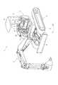
図1は、本実施形態に係る作業車両としての小型油圧ショベル1を示す全体斜視図であり、図2は、油圧ショベル1をオペレータシート6側から前方側を見た図である。
図1、図2において、油圧ショベル1は、クローラ式の下部走行体2の上部に上部旋回体3を旋回自在に搭載した構成であり、下部走行体2の前側には油圧アクチュエータによりリフト動作可能なブレード4が設けられ、上部旋回体3の前側には作業機5が設けられている。作業機5は、ブーム、アーム、バケットをそれぞれ個別の油圧アクチュエータで駆動する周知のものであるため、ここでの詳細な説明を省略する。Hereinafter, an embodiment of the present invention will be described with reference to the drawings.
FIG. 1 is an overall perspective view showing a small excavator 1 as a work vehicle according to the present embodiment, and FIG. 2 is a view of the excavator 1 as seen from the
1 and 2, a hydraulic excavator 1 has a configuration in which an
上部旋回体3には、オペレータシート6の左右位置に作業機操作レバー7,7が設けられ、フロアの前側に走行レバー8,8やブームスイング用の操作ペダル9などが設けられている。また、本実施形態の油圧ショベル1はキャノピ仕様であり、オペレータシート6の頭上には、上部旋回体3に立設された2本の支柱11によって支持されるルーフ12が設けられている。さらに、このような油圧ショベル1において、走行レバー8の側方には、フロアに立設された支持フレーム13に支持されるモニタ装置20が設けられている。図2に示すモニタ装置20の位置は、一例であってオペレータシート6の右側にあるコンソールに位置する場合もある。 The
モニタ装置20は、詳細には図3に基づいて説明するが、表示部としての液晶ディスプレイを備えて構成され、複数の操作ボタンを操作することで表示内容を切り換えることが可能である。表示内容としては、サービスメータ、エンジン水温計、エンジン燃料計、予熱モニタ、エンジン油圧モニタ、走行増速モニタ、電気システム警告モニタ、燃費計、現在時刻等である。なお、モニタ装置20は、液晶ディスプレイ上に複数の操作スイッチを組み込み、表示機能と操作機能を一体化したタッチパネルであってもよい。また、表示部としては、液晶ディスプレイの他、有機エレクトロルミネッセンスであってもよい。 Although the
図3は、モニタ装置20を示す分解斜視図である。
図3において、モニタ装置20は、それぞれ有底箱形状のフロントケース22およびリアケース23で構成された外装ケース21を備える。フロントケース22は、正面部22Aが透明のアクリル樹脂、それ以外の側面部22Bが黒色のAES(acrylonitrile/ethylene-propylene-diene/styrene)樹脂からなる2色成形にて形成されている。リアケース23は、全体が黒色のABS(acrylonitrile-butadiene-styrene)樹脂の成形品である。なお、フロントケース22及びリアケース23は黒色でなく他の色であってもよい。AES樹脂は、ABS樹脂よりもさらに耐候性に優れた材料である。よって、本実施形態に係るような作業車両に搭載され、外界にさらされるモニタ装置においては、そのフロントケースにAES樹脂を適用することが好ましい。FIG. 3 is an exploded perspective view showing the
In FIG. 3, the
フロントケース22の透明な正面部22Aの裏側には、矩形状の収容部50(図4、図5、図6)が設けられており、この収容部50内には、薄板状の樹脂枠材24を介して液晶ディスプレイ25が収容される。この際、液晶ディスプレイ25の外周を形成している金属製の額縁材25Aには、弾性を有するゴム枠材26が嵌め込まれており、このゴム枠材26によって液晶ディスプレイ25に加わる振動が吸収され、液晶ディスプレイ25の耐久性の確保が図られているとともに、樹脂製のフロントケース22と金属製の額縁材25Aとの熱膨張差が吸収され、フロントケース22あるいは液晶ディスプレイ25の破損防止が図られるようになっている。ゴム枠材26の詳細については、後述する。 A rectangular accommodating portion 50 (FIGS. 4, 5, and 6) is provided on the back side of the transparent
組み立てられたモニタ装置20は、液晶ディスプレイ25の表示面38A(フィニッシャシート38の表示面)と操作ボタン38B(ノブスイッチ37の上にフィニッシャシート38が覆いかぶさる部分)とは、ほぼ同一平面上となっている。液晶ディスプレイ25の周囲(図3に示すように液晶ディスプレイ25から見て、Yの正方向側およびZの負方向側の位置)には、L字形状のスイッチ基板27が配置される。また、表示面38Aの周囲にL字状に操作ボタン(図3参照)が配置される。ここで、本実施例(図3)では、縦に4個、横に4個の操作ボタンを配置しているが、これは一例であって、この操作ボタンの数は、モニタ装置20の機能に応じた個数を設けることができる。スイッチ基板27は、操作ボタンの位置及び数に応じたスイッチ27B(タクトスイッチ)がマウントされたものであり、操作面のいずれかの操作ボタン38Bを押すと、ノブスイッチ37が図3に示すXの負の方向に動き、ノブスイッチ37の先端が、スイッチ基板27にマウントされたスイッチ27Bの表面を押し込み、スイッチ27Bは電気信号を生成する。その電気信号は、モニタ基板29に送信され、例えば操作ボタンの操作が、液晶ディスプレイ25の画面を所定の画面に遷移させることを目的とするものであれば、モニタ基板29から画面遷移のための制御信号が、液晶ディスプレイ25に一体に組み込まれた図示しない駆動回路用基板に送信される。 In the assembled
スイッチ基板27は、正面部22Aと一体で、かつリアケース23側に向けて突出するように形成された複数の取付ボス27C(図5)上にビス27Aにてビス止めされる。正面部22Aには、同様な複数の別の取付ボス28B(図5)が設けられ、これらの取付ボス28B上には、樹脂製のホルダ28がビス28Aにてビス止めされる。ホルダ28の正面(図3に示すXの正方向)には、ゴム製の押圧部材32が上下左右の4箇所に離間して取り付けられている。ホルダ28は、取付ボス28Bに取り付けられた状態では、これらの押圧部材32を介して液晶ディスプレイ25を裏面側(図3に示すXの負方向側)から押圧し、収容部50内で液晶ディスプレイ25が位置ずれしないように保持している。 The
正面部22Aの四隅および他の一箇所には、さらに別の取付ボス29B(図5)が形成されている。これらの取付ボス29B上には、液晶ディスプレイ25用の電源回路および制御回路が形成されたモニタ基板29があてがわれている。なお、ホルダ28とモニタ基板29とは所定の間隔(図3に示すX方向に離間した間隔)で離間させて配置される。そして、以上に述べた各部品がフロントケース22の中に収容され、その状態でリアケース23が、ウレタン製のガスケット31を介してフロントケース22に嵌め込まれ、取り付けられる。リアケース23は、モニタ基板29があてがわれた取付ボス29Bに対してビス29Aにてビス止めし取り付けられる。すなわち、モニタ基板29は、リアケース23と共締めされるのであり、取付ボス29Bとリアケース23のビス挿通部23G(図3)との間に挟持された状態で取り付けられる。 Further mounting
また、スイッチ基板27とモニタ基板29とは、フラットケーブル33で電気的に接続され、モニタ基板29と液晶ディスプレイ25に一体に組み込まれた駆動回路用の駆動基板30(図5)とは、フラットケーブル35で同様に接続される。なお、駆動基板30は、モニタ基板29からの制御信号を受けて、液晶ディスプレイ25にどのような色を表示するかといった表示制御を行うためのものである。
そして、モニタ基板29の裏面側(図3に示すXの負の方向側)には、外部からの電源供給および信号通信用のケーブルが接続されるコネクタ(ソケット)34が実装されている。コネクタ34は、リアケース23に設けられた開口部23Aを通して外部に露出する。リアケース23内の開口部23A回りには、ウレタン製のガスケット36が貼り付けられ、開口部23Aとコネクタ34との間に生じる隙間を塞いでいる。以上に説明したように、モニタ装置20は、外部からの水や埃が内部に侵入しないような気密構造となっている。The
A connector (socket) 34 to which an external power supply and signal communication cable is connected is mounted on the back side of the monitor board 29 (the negative direction side of X shown in FIG. 3). The
一方、フロントケース22の正面部22Aには、リアケース23側に突出した複数の筒状の挿入部37A(図5)が設けられ、これらの挿入部37Aには、正面側からノブスイッチ37が挿入される。ノブスイッチ37の先端には、スイッチ基板27に実装されたスイッチ27Bが位置している。前述のようにフィニッシャシート38の上からノブスイッチ37を押圧操作することで、スイッチ27Bを操作することが可能であり、液晶ディスプレイ25の表示内容を切り換えることなどができる。上記のようにタッチパネルを用いる場合は、ノブスイッチ37およびスイッチ27Bの機能がタッチパネル上に組み込まれることとなるため、ノブスイッチ37は不要となる。ただし、タッチパネルに機能を持たせず独自にノブスイッチ37に特定の機能を持たせ、タッチパネルとノブスイッチ37およびスイッチ27Bとを併存させたモニタ装置20であってもよい。
正面部22Aには、そのようなノブスイッチ37までも被うように、樹脂製のフィニッシャシート38が貼設される。On the other hand, the
A
以上に説明した各部品は、図3に示すように、樹脂枠材24からモニタ基板29までの各部品がフロントケース22内に収容されるが、これらのうちモニタ基板29に実装されたコネクタ34だけがフロントケース22から、図3で示すXの負の方向(リアケース23側)にはみ出すことになる。このため、組み立てられたモニタ装置20において、リアケース23は、その内部に大容量の内部空間を有しているが、この内部空間内にはコネクタ34のみが位置し、大部分がそのままの空間として存在する。つまり、リアケース23の大きな内部空間は、リアケース23の表面部23Bの表面積を意図的に大きくしたことにより生じた空間であり、表面部23Bの表面積を大きくすることで、モニタ基板29や液晶ディスプレイ25から発した熱が表面部23Bを通して外部に効率的に放熱するようになっている。リアケース23の大きな内部空間は、モニタ装置20としては、図3に示すX方向に寸法が大きくなることになるが、作業車両を使った掘削作業などの作業中のオペレータの視線方向は、X方向になるため、モニタ装置20が図3に示すY方向あるいはZ方向に大きくならなければ、作業中におけるオペレータの視界を妨げることにならならず、作業性に影響を与えない。 As shown in FIG. 3, each component described above is accommodated in the
図4は、液晶ディスプレイ25およびゴム枠材26を示す斜視図である。図4において、液晶ディスプレイ25は、その正面側に金属製の額縁材25Aを備えている。額縁材25Aは、亜鉛メッキ鋼板などの金属板をプレス等による打抜加工後に曲げ加工を施すことで製作されており、液晶ディスプレイ25の正面側である表示画面側の周縁に対応して設けられた枠状部25Bと、枠状部25Bから折り曲げられて液晶ディスプレイ25の各側面に係止される係止片部25Cと、その折り曲げられた部分である折曲部25Dとを有する。 FIG. 4 is a perspective view showing the
一方のゴム枠材26は、額縁材25Aの枠状部25Bにあてがわれるようにして液晶ディスプレイ25の表示画面側の周縁を覆う張出部26Aと、張出部26Aに対して一体成形されて、液晶ディスプレイ25の四周の外周面を囲う囲い面部26Bとを備える。ゴム枠材26の材質は特に限定されるものではないが、本実施形態ではニトリルゴムが用いられる。この他、シリコーンゴムなど、工業用製品として一般的に用いられる弾性変形可能な材質を適用できる。 One
囲い面部26Bの各側面の表面には、液晶ディスプレイ25の収容部50への収容方向に沿った2個の突起部26Cが互いに離間して設けられている。収容方向とは、ゴム枠材26を液晶ディスプレイ25へ取り付ける方向と同じ方向(図3に示すX方向)である。各突起部26Cは、囲い面部26Bの幅寸法と同じ長さ寸法を有し、当該幅寸法内で連続して設けられている。 On the surface of each side surface of the
図5には、ゴム枠材26が取り付けられた液晶ディスプレイ25を収容部50内に収容した状態が示されている。この状態では、突起部26Cは、収容部50の内周面53との接触部分においてつぶれた状態で接触している。内周面53と囲い面部26Bの表面(突起部26Cを除く表面)とは接触していない。すなわち、ゴム枠材26と収容部50の内周面53とは、8箇所の突起部26Cで接触しており、ゴム枠材26が取り付けられた液晶ディスプレイ25を収容部50内に収容する際、突起部26Cと内周面53とが最小限の接触面積で接触しながら収容されるため、滑らかに液晶ディスプレイ25を収容部50に収容することができる。つまり、このようなゴム枠材26を用いることで、ゴム枠材26が取り付けられた液晶ディスプレイ25を収容部50に収容する際の摩擦抵抗が格段に低くなり、組立性に優れるのである。 FIG. 5 shows a state in which the
液晶ディスプレイ25が収容部50に収容され、モニタ装置20として組み上げられ、油圧ショベル1に搭載され、モニタ装置20の外部から振動が伝播しても、突起部26Cが弾性材であるため、収容部50内での液晶ディスプレイ25が受ける振動をゴム枠材26の全体で吸収でき、モニタ装置20の耐振性能を確保することができる。一方、外気温度の変化によって、液晶ディスプレイ25側の例えば額縁材25Aと収容部50との熱膨張あるいは熱収縮の度合いの差が、材質の違いから発生する。すなわち、熱の影響で液晶ディスプレイ25の額縁材25Aと収容部50の内周面53との接触力が変わる。しかし、接触力の変化に応じて突起部26Cが弾性変形することで、接触力の変化が生じても接触力を緩和し、液晶ディスプレイ25やフロントケース22の収容部50が損傷することを防止できる。 The
また、平面視で矩形状とされた収容部50の両方の短辺側には、ホルダ28を取り付けるための取付ボス28Bが近接して設けられ、これらの取付ボス28Bは収容部50を外側から補強するリブ54としても機能する。さらに、収容部50の一方の長辺側には、ノブスイッチ37を挿入するための複数の挿入部37Aとの間でリブ55が設けられ、補強されている。他方の長辺側には、対向する壁部22Dとの間でリブ56が設けられ、補強されている。そして、ゴム枠材26の突起部26Cは、そのようなリブ54〜56の近傍に対応して設けられている。突起部26Cがリブ54〜56の近傍に設けられていることで、突起部26Cを介して収容部50側へ伝達される押圧力をリブ54〜56にて確実に受け止めて、収容部50が外側に広がるように変形するのを防止可能である。 In addition, mounting
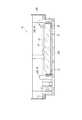
図6は、収容部に液晶ディスプレイ25が収容された状態を示す平面図であり、図5のVI−VI線断面図である。また、図7は、図6での要部を拡大して示す断面斜視図である。図6、図7に示すように、収容部50の正面部22Aの内面57には樹脂枠材24があてがわれ、樹脂枠材24の背面側にはゴム枠材26の張出部26A全域が密着し、樹脂枠材24が緩衝材として機能している。ここで、樹脂枠材24は、液晶ディスプレイ25の額縁材25Aを隠すように設けられており、モニタ装置20の外部から額縁材25Aを見え難くすることで意匠性の向上が図られている。ゴム枠材26の張出部26Aは、その幅寸法W1が額縁材25Aの枠状部25Bの幅寸法W2よりも大幅に小さく(本実施形態では大凡、W2=2×W1である)。この結果、張出部26Aは、額縁材25Aの枠状部25Bのうち、係止片部25Cとの境界である折曲部25D寄りの領域に対応する範囲に設けられており、当該折曲部25Dに近い部分で樹脂枠材24との間に配置されることになる。 6 is a plan view showing a state in which the
金属板の曲げ加工により作製された額縁材25Aは、折曲部25Dでの剛性が最も大きい。従って、このような折曲部25Dに近い位置の領域に対応する範囲に張出部26Aの幅寸法W1が決められているため、液晶ディスプレイ25を収容部50に収容し組み立てられた際の押圧力が、液晶ディスプレイ25側からゴム枠材26および樹脂枠材24を介して正面部22Aに伝達されても、額縁材25Aの剛性が大きなところで押し付け力を受けることになる。よって、額縁材25Aの変形等が防止され、より大きな押圧力にて液晶ディスプレイ25を確実にフロントケース22に保持したモニタ装置20を実現することが可能である。仮に外気温度の変化によって各部材の熱膨張がおきて押圧力が大きくなっても、上記に説明したように張出部26Aの範囲が定められていることから額縁材25Aの剛性が高いところに押圧力は作用される。従って、外気温度の変化があっても、額縁材25Aの変形等が防止できる。 The
図7に拡大して示すように、ゴム枠材26の突起部26Cは、断面形状(端面形状も同じ)が略半円形をしている。収容部50の内周面53は、背面側(図中の上方側)に向かうに従って拡がるように傾斜(図7に示すA)している。このため、断面半円形とされた突起部26Cは、収容部50の奥側である正面部22Aに近い側で大きく弾性変形し断面がつぶれる一方、収容部50の間口側(図中の上方側)では、線接触に近い状態となり、弾性変形の量が小さい。 As shown in an enlarged view in FIG. 7, the
このことから、ゴム枠材26を取り付けた液晶ディスプレイ25を収容部50内に収容させ組み立てる際、収容部50内に落とし込んで行く初期の時点では、ゴム枠材26の突起部26Cの変形量が少なく、スムーズに収容できるようになっている。さらにゴム枠材26を取り付けた液晶ディスプレイ25を収容部50内に落とし込んで行くに従って、収容部50の奥側の開口面積はせまくなるため、最終的にゴム枠材26を取り付けた液晶ディスプレイ25が収容部50に収容された状態では、突起部26Cと収容部50の内周面53との接触面には所定の接触力が働き、確実に液晶ディスプレイ25が保持されることになる。なお、内周面53の傾斜(A)のテーパ角は、フロントケース22を樹脂成形により成形するための金型に対する抜き勾配として付与される角度よりも大きく、上記のように収容方向に沿って突起部26Cの弾性変形量を異ならせるために意図的に付与された角度である。 Therefore, when the
なお、本発明は前述の実施形態に限定されるものではなく、本発明の目的を達成できる範囲での変形、改良等は本発明に含まれるものである。
例えば、前記実施形態では、本発明のモニタ装置を作業車両の一例として油圧ショベル1に搭載した例で説明したが、本発明では、モニタ装置をホイールローダ等の他の建設機械や、フォークリフト等の産業車両といった作業車両に搭載してもよい。そして、フォークリフトの場合では、フォークリフト特有の表示内容、例えば、フォーク爪の昇降方向や、フォーク爪に掛かる負荷、走行輪に掛かる負荷、走行速度、あるいはバッテリ駆動のフォークリフトでは、バッテリの充電量、電力消費量などを表示してもよい。It should be noted that the present invention is not limited to the above-described embodiments, and modifications, improvements, and the like within the scope that can achieve the object of the present invention are included in the present invention.
For example, in the above-described embodiment, the monitor device of the present invention is described as an example of mounting on the hydraulic excavator 1 as an example of a work vehicle. However, in the present invention, the monitor device may be another construction machine such as a wheel loader or a forklift. You may mount in work vehicles, such as an industrial vehicle. In the case of a forklift, the display content specific to the forklift, for example, the direction in which the fork claw is raised and lowered, the load on the fork claw, the load on the traveling wheel, the traveling speed, or the battery-powered forklift, You may display consumption etc.
前記実施形態では、ゴム枠材26の突起部26Cは、囲い面部26Bの幅寸法と同じ長さに連続して設けられていたが、そのような幅寸法よりも短い長さ寸法、例えば幅寸法の1/2以下の長さ寸法等に設けられてもよい。このような場合には、突起部26Cを張出部26A側に寄せて設けることで、収容部50での液晶ディスプレイ25の保持力を十分に確保できるようになる。また、突起部26Cを、囲い面部26Bの幅寸法内で不連続に設け、それらを直線状に間隔を空けて配置したり、ドット状に設けて分散配置したりする構成でもよい。さらに、突起部26Cの断面形状は、半円形に限らず、断面台形状であったり、断面三角形状、あるいは断面四角形等であったりしてもよい。つまり、本発明に係る突起部の数や形状等は、その実施にあたって任意に決められてよいのである。 In the above-described embodiment, the
本発明は、油圧ショベルやホイールローダ等の建設機械に利用できる他、フォークリフト等の産業車両にも利用できる。 The present invention can be used for construction machines such as a hydraulic excavator and a wheel loader, and can also be used for industrial vehicles such as a forklift.
1…作業車両である油圧ショベル、20…モニタ装置、25…表示部である液晶ディスプレイ、22…収容部を有したケースであるフロントケース、26…ゴム枠材、26A…張出部、26B…囲い面部、26C…突起部、25A…額縁材、25B…枠状部、25C…係止片部、25D…折曲部、53…内周面、54,55,56…リブ。 DESCRIPTION OF SYMBOLS 1 ... Hydraulic excavator which is a working vehicle, 20 ... Monitor apparatus, 25 ... Liquid crystal display which is a display part, 22 ... Front case which is a case with an accommodating part, 26 ... Rubber frame material, 26A ... Overhang | projection part, 26B ... Enclosure surface part, 26C ... projection part, 25A ... frame material, 25B ... frame-like part, 25C ... locking piece part, 25D ... bent part, 53 ... inner peripheral surface, 54, 55, 56 ... rib.
Claims (8)
Translated fromJapanese表示部と、
前記表示部の外周面を囲う囲い面部を有したゴム枠材と、
前記ゴム枠材が取り付けられた前記表示部が収容される収容部を有したケースとを備え、
前記ゴム枠材には、前記囲い面部の表面から突出し、かつ前記収容部の内周面に接触して弾性変形する突起部が設けられており、
前記ゴム枠材の突起部は、当該突起部と対向する前記収容部の内周面とは反対側の面側に設けられた収容部補強用のリブの近傍に位置する
ことを特徴とするモニタ装置。In the monitor device,
A display unit;
A rubber frame member having a surrounding surface portion surrounding an outer peripheral surface of the display portion;
A case having an accommodating portion for accommodating the display portion to which the rubber frame member is attached;
The rubber frame member is provided with a protruding portion that protrudes from the surface of the enclosure surface portion and elastically deforms in contact with the inner peripheral surface of the housing portion,
The projection of the rubber frame member is located in the vicinity of a rib for reinforcing the housing provided on the surface opposite to the inner peripheral surface of the housing facing the projection. apparatus.
前記ゴム枠材は、前記囲い面部と連続して設けられるとともに、前記表示部の表示画面側の周縁を覆う張出部を有する
ことを特徴とするモニタ装置。The monitor device according to claim 1,
The rubber frame member is provided continuously with the surrounding surface portion, and has a projecting portion that covers a peripheral edge of the display portion on the display screen side.
前記表示部の表示画面側には、金属製の額縁材が設けられ、
前記額縁材は、前記表示画面側の周縁に対応して設けられる枠状部と、前記枠状部から折り曲げられて前記表示部の各側面に係止される係止片部と、前記枠状部および前記係止片部の境界である折曲部とを有し、
前記ゴム枠材の前記張出部は、前記額縁材の枠状部のうち、前記折曲部寄りの領域に対応する範囲に設けられている
ことを特徴とするモニタ装置。The monitor device according to claim 2,
On the display screen side of the display unit, a metal frame material is provided,
The frame material includes a frame-shaped portion provided corresponding to a peripheral edge on the display screen side, a locking piece portion bent from the frame-shaped portion and locked to each side surface of the display portion, and the frame-shaped member And a bent portion that is a boundary of the locking piece portion,
The overhanging portion of the rubber frame member is provided in a range corresponding to a region near the bent portion of the frame-like portion of the frame member.
前記収容部の内周面は、前記表示部を収容する間口に向かうに従って拡がるように傾斜している
ことを特徴とするモニタ装置。The monitor device according to any one of claims 1 to3 ,
The monitor device characterized in that an inner peripheral surface of the storage portion is inclined so as to expand toward a front opening for storing the display portion.
前記突起部は、前記囲い面部の幅寸法内で連続して設けられている
ことを特徴とするモニタ装置。The monitor device according to any one of claims 1 to4 ,
The projection is provided continuously within the width dimension of the surrounding surface portion.
前記突起部の断面形状は、略半円形である
ことを特徴とするモニタ装置。The monitor device according to any one of claims 1 to5 ,
A cross-sectional shape of the protrusion is a substantially semicircular shape.
液晶ディスプレイで構成される表示部と、
前記表示部の外周面を囲う囲い面部を有したゴム枠材と、
前記ゴム枠材が取り付けられた前記表示部が収容される収容部を有したケースとを備え、
前記ゴム枠材には、前記囲い面部の表面から突出し、かつ前記収容部の内周面に接触して弾性変形する突起部が設けられ、
前記ゴム枠材の突起部は、当該突起部と対向する前記収容部の内周面とは反対側の面側に設けられた収容部補強用のリブの近傍に位置し、
前記ゴム枠材は、前記囲い面部と連続して設けられるとともに、前記表示部の表示画面側の周縁を覆う張出部を有し、
前記表示部の表示画面側には、金属製の額縁材が設けられ、
前記額縁材は、前記表示画面側の周縁に対応して設けられる枠状部と、前記枠状部から折り曲げられて前記表示部の各側面に係止される係止片部と、前記枠状部および前記係止片部の境界である折曲部とを有し、
前記ゴム枠材の前記張出部は、前記額縁材の枠状部のうち、前記折曲部寄りの領域に対応する範囲に設けられている
ことを特徴とするモニタ装置。A monitoring device mounted in the vicinity of an operator seat of a work vehicle,
A display unit comprising a liquid crystal display;
A rubber frame member having a surrounding surface portion surrounding an outer peripheral surface of the display portion;
A case having an accommodating portion for accommodating the display portion to which the rubber frame member is attached;
The rubber frame member is provided with a protruding portion that protrudes from the surface of the surrounding surface portion and elastically deforms in contact with the inner peripheral surface of the housing portion,
The protruding portion of the rubber frame member is located in the vicinity of a rib for reinforcing the receiving portion provided on the surface side opposite to the inner peripheral surface of the receiving portion facing the protruding portion,
The rubber frame member is provided continuously with the surrounding surface portion, and has a projecting portion that covers a peripheral edge on the display screen side of the display portion,
On the display screen side of the display unit, a metal frame material is provided,
The frame material includes a frame-shaped portion provided corresponding to a peripheral edge on the display screen side, a locking piece portion bent from the frame-shaped portion and locked to each side surface of the display portion, and the frame-shaped member And a bent portion that is a boundary of the locking piece portion,
The overhanging portion of the rubber frame member is provided in a range corresponding to a region near the bent portion of the frame-like portion of the frame member.
ことを特徴とする作業車両。A work vehicle comprising the monitor device according to any one of claims 1 to7 .
Priority Applications (6)
| Application Number | Priority Date | Filing Date | Title |
|---|---|---|---|
| JP2012179007AJP5611290B2 (en) | 2012-08-10 | 2012-08-10 | MONITOR DEVICE AND WORK VEHICLE HAVING THE SAME |
| KR1020137003983AKR101492884B1 (en) | 2012-08-10 | 2012-10-18 | Monitor and working vehicle provided with the monitor |
| PCT/JP2012/076975WO2014024329A1 (en) | 2012-08-10 | 2012-10-18 | Monitor device, and working vehicle equipped with same |
| US13/817,123US9109348B2 (en) | 2012-08-10 | 2012-10-18 | Monitor and working vehicle provided with the monitor |
| CN201280002439.7ACN103748625B (en) | 2012-08-10 | 2012-10-18 | Monitoring arrangement and there is its working truck |
| DE112012006802.5TDE112012006802T5 (en) | 2012-08-10 | 2012-10-18 | Monitor and working vehicle provided with the monitor |
Applications Claiming Priority (1)
| Application Number | Priority Date | Filing Date | Title |
|---|---|---|---|
| JP2012179007AJP5611290B2 (en) | 2012-08-10 | 2012-08-10 | MONITOR DEVICE AND WORK VEHICLE HAVING THE SAME |
Publications (2)
| Publication Number | Publication Date |
|---|---|
| JP2014037682A JP2014037682A (en) | 2014-02-27 |
| JP5611290B2true JP5611290B2 (en) | 2014-10-22 |
Family
ID=50067605
Family Applications (1)
| Application Number | Title | Priority Date | Filing Date |
|---|---|---|---|
| JP2012179007AExpired - Fee RelatedJP5611290B2 (en) | 2012-08-10 | 2012-08-10 | MONITOR DEVICE AND WORK VEHICLE HAVING THE SAME |
Country Status (6)
| Country | Link |
|---|---|
| US (1) | US9109348B2 (en) |
| JP (1) | JP5611290B2 (en) |
| KR (1) | KR101492884B1 (en) |
| CN (1) | CN103748625B (en) |
| DE (1) | DE112012006802T5 (en) |
| WO (1) | WO2014024329A1 (en) |
Families Citing this family (7)
| Publication number | Priority date | Publication date | Assignee | Title |
|---|---|---|---|---|
| EP3326056B1 (en) | 2015-07-17 | 2022-10-12 | Crown Equipment Corporation | Processing device having a graphical user interface for industrial vehicle |
| US9790874B2 (en) | 2016-01-19 | 2017-10-17 | Ford Global Technologies, Llc | Method for mitigating wet-fouling of spark plugs |
| EP3545398B1 (en) | 2016-11-22 | 2023-01-04 | Crown Equipment Corporation | User interface device for industrial vehicle |
| CN110024016B (en)* | 2016-12-12 | 2021-09-07 | 三菱电机株式会社 | display screen |
| US10933814B2 (en) | 2018-07-19 | 2021-03-02 | Clark Equipment Company | Display position for cab with overhead door |
| DE102020212990A1 (en)* | 2020-10-14 | 2022-04-14 | Continental Automotive Gmbh | display device |
| US20250305248A1 (en)* | 2024-03-29 | 2025-10-02 | Takeuchi Mfg. Co., Ltd. | Working Vehicle |
Family Cites Families (13)
| Publication number | Priority date | Publication date | Assignee | Title |
|---|---|---|---|---|
| DE3622458A1 (en)* | 1986-07-04 | 1987-01-02 | H Peter Dipl Ing Nardin | Design of a dashboard in a motor vehicle |
| JP3606893B2 (en)* | 1993-12-29 | 2005-01-05 | 富士通フロンテック株式会社 | LCD unit |
| JP3540176B2 (en)* | 1998-11-13 | 2004-07-07 | 矢崎総業株式会社 | Display device |
| JP2000156569A (en)* | 1998-11-19 | 2000-06-06 | Seiko Epson Corp | Buffer structure of electronic equipment |
| JP2001117076A (en)* | 1999-10-13 | 2001-04-27 | Citizen Electronics Co Ltd | Positioning structure for liquid crystal display device |
| JP4553283B2 (en)* | 2000-08-25 | 2010-09-29 | インターナショナル・ビジネス・マシーンズ・コーポレーション | Holding frame and image display device |
| JP2002365613A (en)* | 2001-06-12 | 2002-12-18 | Sony Corp | Supporting mechanism for liquid crystal display panel in camera device |
| CN2842627Y (en)* | 2005-08-22 | 2006-11-29 | 郭正韡 | Displaying device with video pick-up head |
| JP2009162919A (en)* | 2007-12-28 | 2009-07-23 | Orion Denki Kk | Display device |
| JP5703688B2 (en)* | 2009-11-02 | 2015-04-22 | 東洋製罐株式会社 | Microwave plasma processing apparatus and microwave plasma processing method |
| JP5680936B2 (en)* | 2009-11-30 | 2015-03-04 | 株式会社小松製作所 | Vehicle monitoring device |
| CN102079275B (en)* | 2009-11-30 | 2014-06-11 | 株式会社小松制作所 | Display device for vehicle |
| US8665586B2 (en)* | 2010-11-18 | 2014-03-04 | Delta Electronics, Inc. | Display device |
- 2012
- 2012-08-10JPJP2012179007Apatent/JP5611290B2/ennot_activeExpired - Fee Related
- 2012-10-18KRKR1020137003983Apatent/KR101492884B1/ennot_activeExpired - Fee Related
- 2012-10-18WOPCT/JP2012/076975patent/WO2014024329A1/ennot_activeCeased
- 2012-10-18DEDE112012006802.5Tpatent/DE112012006802T5/ennot_activeWithdrawn
- 2012-10-18USUS13/817,123patent/US9109348B2/ennot_activeExpired - Fee Related
- 2012-10-18CNCN201280002439.7Apatent/CN103748625B/enactiveActive
Also Published As
| Publication number | Publication date |
|---|---|
| JP2014037682A (en) | 2014-02-27 |
| WO2014024329A1 (en) | 2014-02-13 |
| US20140240638A1 (en) | 2014-08-28 |
| DE112012006802T5 (en) | 2015-05-28 |
| CN103748625B (en) | 2016-06-29 |
| KR20140043293A (en) | 2014-04-09 |
| CN103748625A (en) | 2014-04-23 |
| US9109348B2 (en) | 2015-08-18 |
| KR101492884B1 (en) | 2015-02-12 |
Similar Documents
| Publication | Publication Date | Title |
|---|---|---|
| JP5611290B2 (en) | MONITOR DEVICE AND WORK VEHICLE HAVING THE SAME | |
| KR101783736B1 (en) | Construction machinery display device and construction machinery | |
| KR101492883B1 (en) | Monitor and working vehicle provided with the monitor | |
| US10379634B2 (en) | Information processing apparatus and base member | |
| JP5720293B2 (en) | Display device | |
| JP2011132800A (en) | Monitoring device for vehicle | |
| JP2012133199A (en) | Display device | |
| JP5512761B2 (en) | MONITOR DEVICE AND WORK VEHICLE HAVING THE SAME | |
| JP5832694B2 (en) | Vehicle operating device and bicycle | |
| JP2009236217A (en) | Seal member | |
| JP7303477B1 (en) | Electronics | |
| JP2014086358A (en) | Portable electronic apparatus | |
| JP5072259B2 (en) | Display holding parts and portable electronic devices | |
| JP6086296B2 (en) | Panel mounting device with built-in display device | |
| JP6651129B2 (en) | Electronics | |
| JP2016031834A (en) | Electronics | |
| JP6537368B2 (en) | Display device | |
| US20140293520A1 (en) | Switch structure and display device | |
| JP2002192985A (en) | Display device | |
| JP2021057633A (en) | Remote control device | |
| JP2012190922A (en) | Case |
Legal Events
| Date | Code | Title | Description |
|---|---|---|---|
| A131 | Notification of reasons for refusal | Free format text:JAPANESE INTERMEDIATE CODE: A131 Effective date:20140114 | |
| A521 | Request for written amendment filed | Free format text:JAPANESE INTERMEDIATE CODE: A523 Effective date:20140310 | |
| TRDD | Decision of grant or rejection written | ||
| A01 | Written decision to grant a patent or to grant a registration (utility model) | Free format text:JAPANESE INTERMEDIATE CODE: A01 Effective date:20140805 | |
| A61 | First payment of annual fees (during grant procedure) | Free format text:JAPANESE INTERMEDIATE CODE: A61 Effective date:20140902 | |
| R150 | Certificate of patent or registration of utility model | Ref document number:5611290 Country of ref document:JP Free format text:JAPANESE INTERMEDIATE CODE: R150 | |
| R250 | Receipt of annual fees | Free format text:JAPANESE INTERMEDIATE CODE: R250 | |
| LAPS | Cancellation because of no payment of annual fees |