JP5610542B2 - Blade ball embolization device and delivery system - Google Patents
Blade ball embolization device and delivery systemDownload PDFInfo
- Publication number
- JP5610542B2 JP5610542B2JP2011506405AJP2011506405AJP5610542B2JP 5610542 B2JP5610542 B2JP 5610542B2JP 2011506405 AJP2011506405 AJP 2011506405AJP 2011506405 AJP2011506405 AJP 2011506405AJP 5610542 B2JP5610542 B2JP 5610542B2
- Authority
- JP
- Japan
- Prior art keywords
- blade
- hub
- band
- implant
- ball
- Prior art date
- Legal status (The legal status is an assumption and is not a legal conclusion. Google has not performed a legal analysis and makes no representation as to the accuracy of the status listed.)
- Active
Links
- 230000010102embolizationEffects0.000titleclaimsdescription8
- 206010002329AneurysmDiseases0.000claimsabstractdescription63
- 238000000034methodMethods0.000claimsabstractdescription63
- 238000004519manufacturing processMethods0.000claimsabstractdescription12
- 230000003073embolic effectEffects0.000claimsabstractdescription11
- 239000000853adhesiveSubstances0.000claimsdescription25
- 230000001070adhesive effectEffects0.000claimsdescription25
- 239000003550markerSubstances0.000claimsdescription11
- 230000002792vascularEffects0.000claimsdescription8
- 239000000463materialSubstances0.000claimsdescription5
- 238000009966trimmingMethods0.000claimsdescription2
- 239000007943implantSubstances0.000abstractdescription117
- 238000011282treatmentMethods0.000abstractdescription10
- 238000013461designMethods0.000abstractdescription6
- 239000010410layerSubstances0.000description48
- 230000017531blood circulationEffects0.000description13
- 229910001000nickel titaniumInorganic materials0.000description10
- BASFCYQUMIYNBI-UHFFFAOYSA-NplatinumChemical compound[Pt]BASFCYQUMIYNBI-UHFFFAOYSA-N0.000description10
- 230000006835compressionEffects0.000description9
- 238000007906compressionMethods0.000description9
- HLXZNVUGXRDIFK-UHFFFAOYSA-Nnickel titaniumChemical compound[Ti].[Ti].[Ti].[Ti].[Ti].[Ti].[Ti].[Ti].[Ti].[Ti].[Ti].[Ni].[Ni].[Ni].[Ni].[Ni].[Ni].[Ni].[Ni].[Ni].[Ni].[Ni].[Ni].[Ni].[Ni]HLXZNVUGXRDIFK-UHFFFAOYSA-N0.000description9
- 238000005520cutting processMethods0.000description8
- 239000011159matrix materialSubstances0.000description8
- 210000004204blood vesselAnatomy0.000description7
- 230000036961partial effectEffects0.000description7
- 229920000642polymerPolymers0.000description7
- 239000003292glueSubstances0.000description6
- 230000008569processEffects0.000description6
- 210000001519tissueAnatomy0.000description6
- 201000008450Intracranial aneurysmDiseases0.000description5
- 230000009471actionEffects0.000description5
- 230000008901benefitEffects0.000description5
- 230000000694effectsEffects0.000description5
- 239000000835fiberSubstances0.000description5
- 238000004873anchoringMethods0.000description4
- 238000000576coating methodMethods0.000description4
- 238000011084recoveryMethods0.000description4
- 229910001220stainless steelInorganic materials0.000description4
- 230000002745absorbentEffects0.000description3
- 239000002250absorbentSubstances0.000description3
- 238000007792additionMethods0.000description3
- 238000005452bendingMethods0.000description3
- 230000015572biosynthetic processEffects0.000description3
- 239000003795chemical substances by applicationSubstances0.000description3
- 239000011248coating agentSubstances0.000description3
- 238000007667floatingMethods0.000description3
- 238000000227grindingMethods0.000description3
- 238000009998heat settingMethods0.000description3
- 230000010354integrationEffects0.000description3
- 238000012986modificationMethods0.000description3
- 230000004048modificationEffects0.000description3
- 238000012545processingMethods0.000description3
- 239000010935stainless steelSubstances0.000description3
- RKDVKSZUMVYZHH-UHFFFAOYSA-N1,4-dioxane-2,5-dioneChemical compoundO=C1COC(=O)CO1RKDVKSZUMVYZHH-UHFFFAOYSA-N0.000description2
- 238000012276Endovascular treatmentMethods0.000description2
- JOYRKODLDBILNP-UHFFFAOYSA-NEthyl urethaneChemical compoundCCOC(N)=OJOYRKODLDBILNP-UHFFFAOYSA-N0.000description2
- GRYLNZFGIOXLOG-UHFFFAOYSA-NNitric acidChemical compoundO[N+]([O-])=OGRYLNZFGIOXLOG-UHFFFAOYSA-N0.000description2
- 208000007536ThrombosisDiseases0.000description2
- RTAQQCXQSZGOHL-UHFFFAOYSA-NTitaniumChemical compound[Ti]RTAQQCXQSZGOHL-UHFFFAOYSA-N0.000description2
- 238000004026adhesive bondingMethods0.000description2
- 239000008280bloodSubstances0.000description2
- 210000004369bloodAnatomy0.000description2
- 230000036760body temperatureEffects0.000description2
- 238000010276constructionMethods0.000description2
- 239000003814drugSubstances0.000description2
- 239000002355dual-layerSubstances0.000description2
- 238000005516engineering processMethods0.000description2
- 239000000017hydrogelSubstances0.000description2
- 230000000670limiting effectEffects0.000description2
- 208000017376neurovascular diseaseDiseases0.000description2
- 229910017604nitric acidInorganic materials0.000description2
- 238000012856packingMethods0.000description2
- 229910052697platinumInorganic materials0.000description2
- 239000004810polytetrafluoroethyleneSubstances0.000description2
- 229920001343polytetrafluoroethylenePolymers0.000description2
- 230000002829reductive effectEffects0.000description2
- 150000003839saltsChemical class0.000description2
- 238000007493shaping processMethods0.000description2
- 239000002356single layerSubstances0.000description2
- 229910052719titaniumInorganic materials0.000description2
- 239000010936titaniumSubstances0.000description2
- YFHICDDUDORKJB-UHFFFAOYSA-Ntrimethylene carbonateChemical compoundO=C1OCCCO1YFHICDDUDORKJB-UHFFFAOYSA-N0.000description2
- 230000037303wrinklesEffects0.000description2
- JJTUDXZGHPGLLC-IMJSIDKUSA-N4511-42-6Chemical compoundC[C@@H]1OC(=O)[C@H](C)OC1=OJJTUDXZGHPGLLC-IMJSIDKUSA-N0.000description1
- USEDHSLPPZQXHL-UHFFFAOYSA-NCC1C(C2CC3)C2C3CC1Chemical compoundCC1C(C2CC3)C2C3CC1USEDHSLPPZQXHL-UHFFFAOYSA-N0.000description1
- 229910000684Cobalt-chromeInorganic materials0.000description1
- 208000005189EmbolismDiseases0.000description1
- 239000004812Fluorinated ethylene propyleneSubstances0.000description1
- 239000004696Poly ether ether ketoneSubstances0.000description1
- 229910001069Ti alloyInorganic materials0.000description1
- 208000009443Vascular MalformationsDiseases0.000description1
- QCWXUUIWCKQGHC-UHFFFAOYSA-NZirconiumChemical compound[Zr]QCWXUUIWCKQGHC-UHFFFAOYSA-N0.000description1
- 229910001093Zr alloyInorganic materials0.000description1
- WAIPAZQMEIHHTJ-UHFFFAOYSA-N[Cr].[Co]Chemical compound[Cr].[Co]WAIPAZQMEIHHTJ-UHFFFAOYSA-N0.000description1
- 230000003044adaptive effectEffects0.000description1
- 230000002411adverseEffects0.000description1
- 229910045601alloyInorganic materials0.000description1
- 239000000956alloySubstances0.000description1
- 238000013459approachMethods0.000description1
- 229910052788bariumInorganic materials0.000description1
- DSAJWYNOEDNPEQ-UHFFFAOYSA-Nbarium atomChemical compound[Ba]DSAJWYNOEDNPEQ-UHFFFAOYSA-N0.000description1
- 210000001841basilar arteryAnatomy0.000description1
- JUPQTSLXMOCDHR-UHFFFAOYSA-Nbenzene-1,4-diol;bis(4-fluorophenyl)methanoneChemical compoundOC1=CC=C(O)C=C1.C1=CC(F)=CC=C1C(=O)C1=CC=C(F)C=C1JUPQTSLXMOCDHR-UHFFFAOYSA-N0.000description1
- 229910002056binary alloyInorganic materials0.000description1
- 239000000560biocompatible materialSubstances0.000description1
- 229920002988biodegradable polymerPolymers0.000description1
- 239000004621biodegradable polymerSubstances0.000description1
- 230000004071biological effectEffects0.000description1
- 230000031018biological processes and functionsEffects0.000description1
- 230000036772blood pressureEffects0.000description1
- 238000009954braidingMethods0.000description1
- 210000004556brainAnatomy0.000description1
- 238000004140cleaningMethods0.000description1
- 239000011247coating layerSubstances0.000description1
- 239000010952cobalt-chromeSubstances0.000description1
- 239000002131composite materialSubstances0.000description1
- 229920001577copolymerPolymers0.000description1
- 230000007797corrosionEffects0.000description1
- 238000005260corrosionMethods0.000description1
- 230000006378damageEffects0.000description1
- 230000003247decreasing effectEffects0.000description1
- 238000002716delivery methodMethods0.000description1
- 229910003460diamondInorganic materials0.000description1
- 239000010432diamondSubstances0.000description1
- 238000004090dissolutionMethods0.000description1
- 235000012489doughnutsNutrition0.000description1
- 229940079593drugDrugs0.000description1
- 230000009977dual effectEffects0.000description1
- 230000001747exhibiting effectEffects0.000description1
- 238000011049fillingMethods0.000description1
- PCHJSUWPFVWCPO-UHFFFAOYSA-NgoldChemical compound[Au]PCHJSUWPFVWCPO-UHFFFAOYSA-N0.000description1
- 229910052737goldInorganic materials0.000description1
- 239000010931goldSubstances0.000description1
- 238000010438heat treatmentMethods0.000description1
- 230000000004hemodynamic effectEffects0.000description1
- 230000008595infiltrationEffects0.000description1
- 238000001764infiltrationMethods0.000description1
- 239000007788liquidSubstances0.000description1
- 229910000734martensiteInorganic materials0.000description1
- 230000013011matingEffects0.000description1
- QSHDDOUJBYECFT-UHFFFAOYSA-NmercuryChemical compound[Hg]QSHDDOUJBYECFT-UHFFFAOYSA-N0.000description1
- 229910052753mercuryInorganic materials0.000description1
- 229910052751metalInorganic materials0.000description1
- 239000002184metalSubstances0.000description1
- 239000000203mixtureSubstances0.000description1
- 210000003205muscleAnatomy0.000description1
- LNOPIUAQISRISI-UHFFFAOYSA-Nn'-hydroxy-2-propan-2-ylsulfonylethanimidamideChemical compoundCC(C)S(=O)(=O)CC(N)=NOLNOPIUAQISRISI-UHFFFAOYSA-N0.000description1
- 229910001120nichromeInorganic materials0.000description1
- 210000002445nippleAnatomy0.000description1
- 238000004806packaging method and processMethods0.000description1
- 238000002161passivationMethods0.000description1
- 230000001575pathological effectEffects0.000description1
- 230000035515penetrationEffects0.000description1
- 229920009441perflouroethylene propylenePolymers0.000description1
- 229920002530polyetherether ketonePolymers0.000description1
- 239000012858resilient materialSubstances0.000description1
- 230000000284resting effectEffects0.000description1
- 235000013580sausagesNutrition0.000description1
- 238000000926separation methodMethods0.000description1
- 230000035939shockEffects0.000description1
- 238000004513sizingMethods0.000description1
- 238000010561standard procedureMethods0.000description1
- 239000003356suture materialSubstances0.000description1
- GUVRBAGPIYLISA-UHFFFAOYSA-Ntantalum atomChemical compound[Ta]GUVRBAGPIYLISA-UHFFFAOYSA-N0.000description1
- 229910002058ternary alloyInorganic materials0.000description1
- 229940124597therapeutic agentDrugs0.000description1
- 230000002885thrombogenetic effectEffects0.000description1
- 210000005166vasculatureAnatomy0.000description1
- 238000009941weavingMethods0.000description1
- 238000003466weldingMethods0.000description1
- 229910052726zirconiumInorganic materials0.000description1
- PAPBSGBWRJIAAV-UHFFFAOYSA-Nε-CaprolactoneChemical compoundO=C1CCCCCO1PAPBSGBWRJIAAV-UHFFFAOYSA-N0.000description1
Images


Classifications
- A—HUMAN NECESSITIES
- A61—MEDICAL OR VETERINARY SCIENCE; HYGIENE
- A61B—DIAGNOSIS; SURGERY; IDENTIFICATION
- A61B17/00—Surgical instruments, devices or methods
- A61B17/12—Surgical instruments, devices or methods for ligaturing or otherwise compressing tubular parts of the body, e.g. blood vessels or umbilical cord
- A61B17/12022—Occluding by internal devices, e.g. balloons or releasable wires
- A61B17/12027—Type of occlusion
- A61B17/12031—Type of occlusion complete occlusion
- A—HUMAN NECESSITIES
- A61—MEDICAL OR VETERINARY SCIENCE; HYGIENE
- A61B—DIAGNOSIS; SURGERY; IDENTIFICATION
- A61B17/00—Surgical instruments, devices or methods
- A61B17/12—Surgical instruments, devices or methods for ligaturing or otherwise compressing tubular parts of the body, e.g. blood vessels or umbilical cord
- A61B17/12022—Occluding by internal devices, e.g. balloons or releasable wires
- A61B17/12099—Occluding by internal devices, e.g. balloons or releasable wires characterised by the location of the occluder
- A61B17/12109—Occluding by internal devices, e.g. balloons or releasable wires characterised by the location of the occluder in a blood vessel
- A—HUMAN NECESSITIES
- A61—MEDICAL OR VETERINARY SCIENCE; HYGIENE
- A61B—DIAGNOSIS; SURGERY; IDENTIFICATION
- A61B17/00—Surgical instruments, devices or methods
- A61B17/12—Surgical instruments, devices or methods for ligaturing or otherwise compressing tubular parts of the body, e.g. blood vessels or umbilical cord
- A61B17/12022—Occluding by internal devices, e.g. balloons or releasable wires
- A61B17/12131—Occluding by internal devices, e.g. balloons or releasable wires characterised by the type of occluding device
- A61B17/12159—Solid plugs; being solid before insertion
- A—HUMAN NECESSITIES
- A61—MEDICAL OR VETERINARY SCIENCE; HYGIENE
- A61B—DIAGNOSIS; SURGERY; IDENTIFICATION
- A61B17/00—Surgical instruments, devices or methods
- A61B17/12—Surgical instruments, devices or methods for ligaturing or otherwise compressing tubular parts of the body, e.g. blood vessels or umbilical cord
- A61B17/12022—Occluding by internal devices, e.g. balloons or releasable wires
- A61B17/12099—Occluding by internal devices, e.g. balloons or releasable wires characterised by the location of the occluder
- A61B17/12109—Occluding by internal devices, e.g. balloons or releasable wires characterised by the location of the occluder in a blood vessel
- A61B17/12113—Occluding by internal devices, e.g. balloons or releasable wires characterised by the location of the occluder in a blood vessel within an aneurysm
- A61B17/12118—Occluding by internal devices, e.g. balloons or releasable wires characterised by the location of the occluder in a blood vessel within an aneurysm for positioning in conjunction with a stent
- A—HUMAN NECESSITIES
- A61—MEDICAL OR VETERINARY SCIENCE; HYGIENE
- A61B—DIAGNOSIS; SURGERY; IDENTIFICATION
- A61B17/00—Surgical instruments, devices or methods
- A61B17/12—Surgical instruments, devices or methods for ligaturing or otherwise compressing tubular parts of the body, e.g. blood vessels or umbilical cord
- A61B17/12022—Occluding by internal devices, e.g. balloons or releasable wires
- A61B17/12131—Occluding by internal devices, e.g. balloons or releasable wires characterised by the type of occluding device
- A61B17/12136—Balloons
- A—HUMAN NECESSITIES
- A61—MEDICAL OR VETERINARY SCIENCE; HYGIENE
- A61B—DIAGNOSIS; SURGERY; IDENTIFICATION
- A61B17/00—Surgical instruments, devices or methods
- A61B17/12—Surgical instruments, devices or methods for ligaturing or otherwise compressing tubular parts of the body, e.g. blood vessels or umbilical cord
- A61B17/12022—Occluding by internal devices, e.g. balloons or releasable wires
- A61B17/12131—Occluding by internal devices, e.g. balloons or releasable wires characterised by the type of occluding device
- A61B17/1214—Coils or wires
- A61B17/1215—Coils or wires comprising additional materials, e.g. thrombogenic, having filaments, having fibers, being coated
- A—HUMAN NECESSITIES
- A61—MEDICAL OR VETERINARY SCIENCE; HYGIENE
- A61B—DIAGNOSIS; SURGERY; IDENTIFICATION
- A61B17/00—Surgical instruments, devices or methods
- A61B17/12—Surgical instruments, devices or methods for ligaturing or otherwise compressing tubular parts of the body, e.g. blood vessels or umbilical cord
- A61B17/12022—Occluding by internal devices, e.g. balloons or releasable wires
- A61B17/12131—Occluding by internal devices, e.g. balloons or releasable wires characterised by the type of occluding device
- A61B17/12168—Occluding by internal devices, e.g. balloons or releasable wires characterised by the type of occluding device having a mesh structure
- A61B17/12172—Occluding by internal devices, e.g. balloons or releasable wires characterised by the type of occluding device having a mesh structure having a pre-set deployed three-dimensional shape
- A—HUMAN NECESSITIES
- A61—MEDICAL OR VETERINARY SCIENCE; HYGIENE
- A61M—DEVICES FOR INTRODUCING MEDIA INTO, OR ONTO, THE BODY; DEVICES FOR TRANSDUCING BODY MEDIA OR FOR TAKING MEDIA FROM THE BODY; DEVICES FOR PRODUCING OR ENDING SLEEP OR STUPOR
- A61M29/00—Dilators with or without means for introducing media, e.g. remedies
- A61M29/02—Dilators made of swellable material
- A—HUMAN NECESSITIES
- A61—MEDICAL OR VETERINARY SCIENCE; HYGIENE
- A61B—DIAGNOSIS; SURGERY; IDENTIFICATION
- A61B17/00—Surgical instruments, devices or methods
- A61B2017/00526—Methods of manufacturing
- A—HUMAN NECESSITIES
- A61—MEDICAL OR VETERINARY SCIENCE; HYGIENE
- A61B—DIAGNOSIS; SURGERY; IDENTIFICATION
- A61B17/00—Surgical instruments, devices or methods
- A61B2017/00831—Material properties
- A61B2017/00862—Material properties elastic or resilient
- A—HUMAN NECESSITIES
- A61—MEDICAL OR VETERINARY SCIENCE; HYGIENE
- A61B—DIAGNOSIS; SURGERY; IDENTIFICATION
- A61B17/00—Surgical instruments, devices or methods
- A61B2017/00831—Material properties
- A61B2017/00867—Material properties shape memory effect
- A—HUMAN NECESSITIES
- A61—MEDICAL OR VETERINARY SCIENCE; HYGIENE
- A61B—DIAGNOSIS; SURGERY; IDENTIFICATION
- A61B17/00—Surgical instruments, devices or methods
- A61B17/12—Surgical instruments, devices or methods for ligaturing or otherwise compressing tubular parts of the body, e.g. blood vessels or umbilical cord
- A61B17/12022—Occluding by internal devices, e.g. balloons or releasable wires
- A61B2017/1205—Introduction devices
- A61B2017/12054—Details concerning the detachment of the occluding device from the introduction device
- A61B2017/12068—Details concerning the detachment of the occluding device from the introduction device detachable by heat
- A—HUMAN NECESSITIES
- A61—MEDICAL OR VETERINARY SCIENCE; HYGIENE
- A61B—DIAGNOSIS; SURGERY; IDENTIFICATION
- A61B18/00—Surgical instruments, devices or methods for transferring non-mechanical forms of energy to or from the body
- A61B2018/00315—Surgical instruments, devices or methods for transferring non-mechanical forms of energy to or from the body for treatment of particular body parts
- A61B2018/00345—Vascular system
- A61B2018/00404—Blood vessels other than those in or around the heart
- A61B2018/00416—Treatment of aneurisms
- A—HUMAN NECESSITIES
- A61—MEDICAL OR VETERINARY SCIENCE; HYGIENE
- A61B—DIAGNOSIS; SURGERY; IDENTIFICATION
- A61B90/00—Instruments, implements or accessories specially adapted for surgery or diagnosis and not covered by any of the groups A61B1/00 - A61B50/00, e.g. for luxation treatment or for protecting wound edges
- A61B90/39—Markers, e.g. radio-opaque or breast lesions markers
- A61B2090/3966—Radiopaque markers visible in an X-ray image
- Y—GENERAL TAGGING OF NEW TECHNOLOGICAL DEVELOPMENTS; GENERAL TAGGING OF CROSS-SECTIONAL TECHNOLOGIES SPANNING OVER SEVERAL SECTIONS OF THE IPC; TECHNICAL SUBJECTS COVERED BY FORMER USPC CROSS-REFERENCE ART COLLECTIONS [XRACs] AND DIGESTS
- Y10—TECHNICAL SUBJECTS COVERED BY FORMER USPC
- Y10T—TECHNICAL SUBJECTS COVERED BY FORMER US CLASSIFICATION
- Y10T156/00—Adhesive bonding and miscellaneous chemical manufacture
- Y10T156/10—Methods of surface bonding and/or assembly therefor
- Y10T156/1002—Methods of surface bonding and/or assembly therefor with permanent bending or reshaping or surface deformation of self sustaining lamina
- Y10T156/1051—Methods of surface bonding and/or assembly therefor with permanent bending or reshaping or surface deformation of self sustaining lamina by folding
Landscapes
- Health & Medical Sciences (AREA)
- Life Sciences & Earth Sciences (AREA)
- Surgery (AREA)
- Animal Behavior & Ethology (AREA)
- Veterinary Medicine (AREA)
- Vascular Medicine (AREA)
- Public Health (AREA)
- Engineering & Computer Science (AREA)
- Biomedical Technology (AREA)
- Heart & Thoracic Surgery (AREA)
- General Health & Medical Sciences (AREA)
- Molecular Biology (AREA)
- Medical Informatics (AREA)
- Nuclear Medicine, Radiotherapy & Molecular Imaging (AREA)
- Reproductive Health (AREA)
- Neurosurgery (AREA)
- Anesthesiology (AREA)
- Hematology (AREA)
- Surgical Instruments (AREA)
- Prostheses (AREA)
- Media Introduction/Drainage Providing Device (AREA)
Abstract
Description
Translated fromJapanese (背景)
頭蓋内動脈瘤の血管内治療において主流である臨床診療は、血管閉塞コイルの使用が広まった1990年代以来、少々変化してきている。確実に、改良されたカテーテルおよび他の補助装置(例えば、ステント)は、コイリング術をより安全および/またはより効率的とする助けとなっている。しかしながら、妥当で適切な動脈瘤コイルパッキングを達成する技術は、最も高度な技術を有する医師によって、最も最良に実現される。(background)
Clinical practice, the mainstream in endovascular treatment of intracranial aneurysms, has changed slightly since the 1990s when the use of vaso-occlusive coils became widespread. Certainly, improved catheters and other auxiliary devices (eg, stents) help to make coiling safer and / or more efficient. However, the technique to achieve reasonable and proper aneurysm coil packing is best implemented by the most skilled physician.
実行可能な場合、被覆型装置(例えば、本願の譲受人の米国特許出願第12/397,123号に記載されるような)による動脈瘤の排除が好ましい場合がある。ある他の集団は、親血管に動脈瘤外の血流分離器/分流器のステントを配備することにより塞栓形成を達成する、動脈瘤内のコイルパッキングから離れて、パラダイムをシフトしようと試みている。相互に層状に重なる、これらの高密度ブレード装置および/または複数のブレード装置は、塞栓形成をもたらすよう血行動態を変化させる目的で、動脈瘤の頚部を横断して親血管の中に配置される。 Where feasible, it may be preferable to eliminate the aneurysm with a covered device (eg, as described in assignee's assignee's US patent application Ser. No. 12 / 397,123). Some other populations attempt to shift the paradigm away from coil packing within the aneurysm, which achieves embolization by deploying a blood flow separator / shunt stent outside the aneurysm in the parent vessel Yes. These high-density blade devices and / or multiple blade devices, layered on top of each other, are placed in the parent vessel across the neck of the aneurysm for the purpose of altering hemodynamics to result in embolization .
これらWALLSTENT様装置は、側壁動脈瘤を横断する留置に最も適する。しかしながら、末端動脈瘤(例えば、分岐動脈瘤)は、全動脈瘤の発生のうち約60%および80%の間であると推定する者もいる。最も楽観的な数字では、頭蓋内動脈瘤のうち約40%のみが、言及したステント様装置を使用して治療することができる。 These WALLSTENT-like devices are best suited for placement across a sidewall aneurysm. However, some estimate that a terminal aneurysm (eg, a branch aneurysm) is between about 60% and 80% of the total aneurysm occurrence. At the most optimistic number, only about 40% of intracranial aneurysms can be treated using the mentioned stent-like device.
数々の他の装置は、末端動脈瘤に対処するために考え出されてきた。複雑および/または非実用的な配置が、多くに共通している。単に、コイルまたは液体の塞栓剤に対する補助として機能するものもある。これら後者の例では、処置がより一層複雑となり、標準的なコイリング術よりも、より一層優れた医師の技術が必要とされる場合がある。 A number of other devices have been devised to address terminal aneurysms. Complex and / or impractical arrangements are common to many. Some simply serve as an adjunct to the coil or liquid embolic agent. In these latter examples, the procedure becomes more complex and may require physician skills that are even better than standard coiling techniques.
より単純であるが有望な解決法が、DieckらのPCT/US第2007/0076232号に提案されている。動脈瘤頚部から血流をそらすためのブレード/メッシュ円錐部材について、記載されている。装置の基部は、動脈瘤の内側に設定され、一方で分流器部分は、血流を隣接する側枝の方へ動脈瘤から離れるよう方向付けるように、親血管の中へ延びる。移植片は、独立型装置として動脈瘤内に位置付けられるか、接続されたステント様本体によって支持されてもよい。 A simpler but promising solution has been proposed by Dieck et al. In PCT / US2007 / 0076232. A blade / mesh conical member for diverting blood flow from the aneurysm neck is described. The base of the device is set inside the aneurysm, while the shunt portion extends into the parent vessel to direct blood flow away from the aneurysm toward the adjacent side branch. The implant may be positioned within the aneurysm as a stand-alone device or supported by a connected stent-like body.
Mozzochiらの特許文献1および特許文献2は、動脈瘤内に少なくとも部分的に設定される、別の型のブレード血流分離器について開示している。球根状部分は、動脈瘤ドーム内に嵌合するように適合され、頚部を被覆する皮弁によって外側に固着される。分岐動脈瘤がしばしば血管枝構造を組み込む態様に鑑みて、かかるパッチは、しばしば「皮弁」に干渉し、および/または「皮弁」が遊離し、親血管内の潜在的な病理学的血栓形成に有意な問題を引き起こすことがある。 U.S. Pat. Nos. 6,057,086 and 2,096,096, disclose another type of blade blood flow separator that is at least partially set within an aneurysm. The bulbous portion is adapted to fit within the aneurysm dome and is secured to the outside by a flap that covers the neck. In view of the manner in which bifurcated aneurysms often incorporate branch vessel structures, such patches often interfere with the “skin” and / or the “skin” is released, and potential pathological thrombus in the parent vessel May cause significant problems in formation.
本発明の移植片は、上述の装置の各々の欠点に対処する。したがって、主題の移植片(およびそれらの関連送達システム)により、動脈瘤を含む、血管奇形の血管内治療の技術水準を前進させる可能性を提供する。 The implant of the present invention addresses the shortcomings of each of the devices described above. Thus, the subject grafts (and their associated delivery systems) offer the potential to advance the state of the art in endovascular treatment of vascular malformations, including aneurysms.
(本発明の概要)
本発明は、血管内部位で血流を閉塞するための、ワイヤブレードボール移植片を対象とする。送達システムおよびボールを作製する方法についても記載される。ボールは、神経血管障害を治療するのに有用である。頭蓋内動脈瘤の塞栓形成/閉塞に使用されることもあれば、親血管閉塞(PVO)または犠牲で使用されることもある。(Outline of the present invention)
The present invention is directed to a wire blade ball implant for occluding blood flow at an intravascular site. A delivery system and method of making a ball are also described. The ball is useful for treating neurovascular disorders. It may be used for embolization / occlusion of an intracranial aneurysm, or may be used at parent vessel occlusion (PVO) or sacrifice.
一般的に言えば、主題の血管移植片は、ステンレス鋼、コバルトクロム、ニチノール、チタン、チタン合金、ジルコニウムおよびジルコニウム合金、PET(または別の縫合材料)、ならびに医療グレード接着剤より選択される、生物学的に安定した材料の組み合わせを使用するブレード装置である。装置の密度は、ブレード自体が血流に影響を与えるよう意図される用途においては最高レベルであり、ボールによって形成される容積内の血栓が、部位を閉塞することが可能になる。したがって、高密度のブレード/メッシュが通常必要とされる。すなわち、少なくとも約48本の縦糸を有し、通常約90度以上に設定され、直径が約4mmから約8mmのブレードが、用いられてもよい。より大きな直径(例えば、約6mmから12mm以上)では、より多くの縦ワイヤ(例えば、公倍数の64、72、96、128、144)が、ボールを形成するのに用いられてもよい。さらにより目の詰んだ通常ワイヤが用いられてもよい。市販の192および288キャリアの標準ブレード機のうちのいずれか1つが用いられてもよい。その上、3−Dブレード技術(かかるサービスは3Tex,Inc.によって提供されている)が、ボールが形成されるブレードマトリクスを形成するのに用いられてもよい。加えて、ワイヤ直径、ワイヤ数、ブレード角度、および1インチあたりの交差数の任意の組み合わせも、特定の血管部位に適切であるとみなされる塞栓および血流閉塞装置を構成するように、ブレードを作製するのに使用することができる。 Generally speaking, the subject vascular graft is selected from stainless steel, cobalt chromium, nitinol, titanium, titanium alloys, zirconium and zirconium alloys, PET (or another suture material), and medical grade adhesives; A blade device that uses a combination of biologically stable materials. The density of the device is highest in applications where the blade itself is intended to affect blood flow, allowing thrombus within the volume formed by the ball to occlude the site. Therefore, a high density blade / mesh is usually required. That is, a blade having at least about 48 warp yarns, usually set at about 90 degrees or more, and having a diameter of about 4 mm to about 8 mm may be used. For larger diameters (eg, about 6 mm to 12 mm or more), more vertical wires (eg,
様々なワイヤの大きさまたはワイヤの大きさの組み合わせが用いられてもよく、望ましい送達形状(通常、少なくとも神経血管の適応症に対しては、約0.050インチより小さく、より一般的には、抹消PVOの適応症に対しては最大約0.070インチであることが望ましい)によって、通常その範囲は約0.0008インチから約0.0015インチ、最大約0.003インチである。単一のブレードチューブにより、全てのワイヤが同一の直径になってもよく、またはさらなる強度をブレード層に分け与えるように、わずかに厚い直径のワイヤを数本有してもよい。例えば、96ワイヤチューブの半分のワイヤ(すなわち、縦48本)は、例えば、直径0.001”であり得、ワイヤの他方半分は、例えば直径0.0015”であり得る。この場合、ブレードを作製するのに、2つのワイヤの大きさが、通常、均一に織り合わされるであろう。より厚みのあるワイヤは、装置の送達形状を著しく増大させることなく、より大きな強度をブレードに分け与え、ブレードマトリクス密度を満たす一方で、より厚いワイヤによりある強度を提供する。 Various wire sizes or combinations of wire sizes may be used and the desired delivery shape (usually less than about 0.050 inches, more generally at least for neurovascular indications, more generally In general, the range is from about 0.0008 inches to about 0.0015 inches and up to about 0.003 inches. With a single blade tube, all the wires may be the same diameter, or you may have several slightly thicker diameter wires to provide additional strength to the blade layer. For example, a half wire (
ワイヤは、好ましくは、体温において超弾性であるNiTi合金である。金属は、さらなる放射線不透過性を提供する、二元合金または三元合金であってもよい。あるいは、放射線不透過性のプラチナ繊維が、ブレードに含まれてもよく、あるいはワイヤがプラチナまたは金をコアとするニチノールDFTを備えてもよい。さもなければ、ブレードワイヤを(近位端および遠位端の両方またはいずれかで、かつ必要に応じてキャップ間において)固定するように使用される、ハブ、バンド、またはラップ(好ましくはPt)は、唯一の放射線不透過性特徴として機能してもよい。 The wire is preferably a NiTi alloy that is superelastic at body temperature. The metal may be a binary or ternary alloy that provides additional radiopacity. Alternatively, radiopaque platinum fibers may be included in the blade, or the wire may comprise Nitinol DFT with platinum or gold as the core. Otherwise, a hub, band, or wrap (preferably Pt) used to secure the blade wire (either at the proximal and / or distal ends and optionally between the caps) May function as the only radiopaque feature.
形状を熱固定した後、移植片ワイヤの耐食性および/または生体適合性を向上させるために、移植片は、「AYA」スルファミン酸溶液の中でエッチングされ、それから硝酸溶液の中で不動態化されてもよい。あるいはまたはさらに、事前にエッチングおよび/または研磨されたワイヤが、移植片マトリクスを編むのに用いられてもよい。移植片形状の中でのブレードの形状設定は、乾燥器/炉、流動浴槽、または塩鍋の中で行われてもよい。全てのかかる処理は、当業者の知識の範囲内である。 After heat fixing the shape, the implant is etched in an “AYA” sulfamic acid solution and then passivated in a nitric acid solution to improve the corrosion resistance and / or biocompatibility of the graft wire. May be. Alternatively or additionally, pre-etched and / or polished wires may be used to knit the graft matrix. Blade shaping within the implant shape may be done in a dryer / furnace, fluidized bath, or salt pan. All such processing is within the knowledge of one skilled in the art.
特に、形状を熱固定した後、ワイヤは望ましい生物学的効果を促進するために、薬剤でコーティングされてもよい。例えば、ワイヤは、血栓形成剤または内皮化剤、あるいは標的部位で望ましい生物学的プロセスを促進することが可能である他の薬剤でコーティングされることができる。コーティングにより、最終装置の送達形状が許容限度を越えたりしない場合には、ブレードボールはまた、部分的にまたは完全に、ボールの閉塞効果を増大させるように、外面をコーティングされてもよい(例えば、ウレタン等でコーティング)。ヒドロゲルコーティングもまた、WonらのUSPN第6,905,700号に記載されるような、治療薬を封入することができるヒドロゲルベースの高分子網目等、魅力的な選択肢を提供する。 In particular, after heat fixing the shape, the wire may be coated with a drug to promote the desired biological effect. For example, the wire can be coated with a thrombogenic or endothelializing agent or other agent that can facilitate the desired biological process at the target site. If the coating does not cause the delivery shape of the final device to exceed acceptable limits, the blade ball may also be partially or completely coated on the outer surface to increase the occlusion effect of the ball (e.g. , Coated with urethane, etc.). Hydrogel coatings also offer attractive options, such as hydrogel-based polymer networks that can encapsulate therapeutic agents, as described in Won et al. USPN 6,905,700.
同様に、ボールは好都合にニチノールブレードを備える一方で、ブレードは代わりに、ポリマー、特に、形状にするのに熱固定される(例えば、摂氏110度で1時間)、MX−2(MAX−Prene)、合成吸収性モノフィラメント(90/10 グリコリド/L−ラクチド)および/またはG−2(Glycoprene)、合成吸収性モノフィラメント(グリコリド(PGA)、ε−カプロラクトン(PCL)、トリメチレンカーボネート(TMC)コポリマー)等の、高強度生分解性ポリマーといったポリマーを備えてもよい。 Similarly, the ball is conveniently equipped with a Nitinol blade, while the blade is instead heat-set to a polymer, particularly a shape (eg, 110 degrees Celsius for 1 hour), MX-2 (MAX-Prene) ), Synthetic absorbent monofilament (90/10 glycolide / L-lactide) and / or G-2 (Glycoprene), synthetic absorbent monofilament (glycolide (PGA), ε-caprolactone (PCL), trimethylene carbonate (TMC) copolymer Or a polymer such as a high-strength biodegradable polymer.
ある神経血管部位(例えば、遠位の頭蓋内動脈瘤)へ主題の移植片を送達するには、移植片が、狭く蛇行する脳の血管を進む大きさのカテーテルを通過するのに、圧縮可能であることがしばしば必要である。かかる使用に適する標準的な神経血管カテーテルは、管腔直径0.021”および0.027”を有する。特にワイヤの目がより詰んだボールには、0.027”ID(例えば、Cordis Mass Transit Boston Scientific Renegade HI−FLO)、またはそれ以上(例えば、0.044”ID Concentric Merci Distal Access Catherter)の市販されているマイクロカテーテルが好ましい場合がある。固着を確実にするために、より目の詰んだワイヤおよび/またはより大きな直径のワイヤが使用される、PVO適応症に対処するように適応される装置には、移植片は、送達のために5Frおよび/または6Frのガイドカテーテルを必要としてもよい。 To deliver the subject graft to a neurovascular site (eg, a distal intracranial aneurysm), the graft is compressible as it passes through a catheter sized to travel through a narrow, meandering brain vessel It is often necessary. Standard neurovascular catheters suitable for such use have lumen diameters of 0.021 "and 0.027". Especially for balls with tighter wires, 0.027 "ID (e.g. Cordis Mass Transit Boston Regent HI-FLO) or higher (e.g. 0.044" ID Centric Mercury Access Caterer) The microcatheter that is being used may be preferred. For devices adapted to address PVO indications, where more tight wires and / or larger diameter wires are used to ensure fixation, the implant is A 5Fr and / or 6Fr guide catheter may be required.
記載される構成のいずれにおいて、装置は、それ自体の上に折り畳まれ/折り返され、かつより一層密度の高いマトリクスを形成する2つの隣接する層を有する開放体を提供し、血流を閉塞させるように熱固定される、高密度のニチノールブレードを備えてもよい。折り重ねられた(反転された、または裏返された)部分は、放射線不透過性特徴が配置される場合がある、装置の遠位端を画定するように閉じられてもよい。移植片の反対側には、ブレードフィラメントが、少なくとも外側バンドを含むハブの中に担持される。 In any of the described configurations, the device provides an open body that has two adjacent layers that are folded / folded on itself and form a denser matrix to occlude blood flow. A high-density Nitinol blade that is heat-fixed in this manner may be provided. The folded (inverted or flipped) portion may be closed to define the distal end of the device where radiopaque features may be placed. On the opposite side of the implant, the blade filament is carried in a hub that includes at least an outer band.
ハブ内のポートは、任意の取り外し可能な押込器の構成要素を受容することができる。あるいは、移植片は、単純な押込器を使用して、カテーテルを通して配備されることができる。ハブ内のブレードフィラメントは、相互および/またはバンドに溶接されてもよい。あるいは、ブレードおよびハブは、生物適合性接着剤を使用して固定されてもよい。 The port in the hub can receive any removable pusher component. Alternatively, the implant can be deployed through the catheter using a simple pusher. The blade filaments in the hub may be welded to each other and / or to the band. Alternatively, the blade and hub may be secured using a biocompatible adhesive.
弛緩状態では、移植片は、好ましくは円形である開放容積を画定する。送達カテーテルにおいて、移植片は実質的に円筒形の本体に圧縮される。治療部位に配備される時に、移植片は周辺組織に隣接するように拡大し、臨床的に関連のある時間枠において、流れを閉塞させる。 In the relaxed state, the implant defines an open volume that is preferably circular. In the delivery catheter, the implant is compressed into a substantially cylindrical body. When deployed at the treatment site, the graft expands adjacent to the surrounding tissue and occludes flow in a clinically relevant time frame.
取り外し可能な押込器の使用により、装置を(例えば、動脈瘤の中に)配備し、嵌合を確認することが可能になる。その頚部で動脈瘤を閉塞させるように、動脈瘤の中に配備されると、移植片装置は、主として、近位ハブを伴い、頚部の外側のブレードに密接に隣接し、動脈瘤の形状をとる。かかる嵌合を達成するために、移植片は様々な大きさで提供される。これらは、0.5mmから1mmの直径増加の中で進行してもよい。分岐での動脈瘤治療のために、ボール(少なくともその送達構成にある)が、上述のDieckらのものに記載される通り、分流器/ダイバータ型の機能を補助するように、涙滴形をとるのが望ましい場合もある。 The use of a removable pusher allows the device to be deployed (e.g., in an aneurysm) and verified for fit. When deployed in an aneurysm so as to occlude the aneurysm at its neck, the graft device is primarily associated with a proximal hub and is closely adjacent to the outer blade of the neck to shape the aneurysm. Take. To achieve such a fit, the implant is provided in various sizes. These may proceed in a diameter increase from 0.5 mm to 1 mm. For the treatment of aneurysms at bifurcations, the teardrop shape is used so that the ball (at least in its delivery configuration) assists in the function of the shunt / diverter type, as described in Dieck et al. It may be desirable to take.
しかしながら、選択された移植片が望ましいように嵌合しない場合、移植片は単に送達カテーテルの中へ回収されることができる。医用画像によって確認される通り、望ましい嵌合が達成されれば(第1の移植片または置換で)、移植片は解放される。 However, if the selected implant does not fit as desired, the implant can simply be retrieved into the delivery catheter. If the desired fit is achieved (with the first implant or replacement) as confirmed by the medical image, the implant is released.
電解解放GDC型継ぎ手は、解放まで移植片を押込器に固定したまま保つように使用することができる。適切な電解剥離システムに関する詳細は、正しく理解されることが可能で、GuglielmiのUSPN第5,122,136号およびそれに続く出願において教授される通り、現行システムに適用されることができ、それらの全ては本明細書に参考として援用される。別の電動剥離法では、移植片を送達押込器/ガイドに接続する、溶解可能な繊維または縫合接合部が用いられる。かかるシステムにおいて、重合体のコアは、コアに担持されるらせん巻きの導電性リボンで構成されてもよい。電圧を加えると、十分な電流がリボンを通って、リボンに接続するワイヤブリッジへと伝えられる。任意ではニクロムワイヤであるブリッジに沿って発生する熱により、移植片を解放するために、ブリッジ上に結び付けられるか、またはブリッジに隣接して延びている縫合が切断される。適切な縫合溶解剥離システムのさらなる詳細は、援用された仮出願に記載されている。 Electrolytic release GDC type joints can be used to keep the implant secured to the pusher until release. Details regarding a suitable electrolytic stripping system can be properly understood and can be applied to current systems, as taught in Guglielmi USPN 5,122,136 and subsequent applications, All are hereby incorporated by reference. Another motorized release method uses a dissolvable fiber or suture joint that connects the graft to the delivery pusher / guide. In such a system, the polymer core may be comprised of a spirally wound conductive ribbon carried on the core. When voltage is applied, sufficient current is transferred through the ribbon to the wire bridge that connects to the ribbon. The heat generated along the bridge, optionally a nichrome wire, cuts the suture tied to or extending adjacent to the bridge to release the implant. Further details of a suitable suture dissolve release system are described in the incorporated provisional application.
しかしながら、機械式剥離システムがより好ましい場合もある。本発明の局面は、少なくとも1つの部材により、移植片を押込器上に解放可能なように係止する移植片ハブポートに/で、機械的干渉が提供される押込器に関する。1つの方法では、ポートに通される押込器の拡張部から退出するワイヤまたはリボンにより、それが回収されるまで、かかる干渉が生成される。別の例では、複数のワイヤ/リボンが、ポートを介して受容される。1つ以上(通常2つまたは3つ)のこれらワイヤは、押込器カテーテル本体を通って、近位のハンドルインターフェースにまで延びる。ポートを介して受容される、最終「固着」ワイヤもまた、ハンドルにまで延びてもよい。固着ワイヤは、他の「制御」ワイヤがそこから一掃された後にのみ、ハブポートから退出できる大きさの頭部を含む。頭部は、好ましくは、レーザまたはプラズマ加熱/溶解によって形成される。ハンドルは、最初に制御ワイヤを除去し、それから(任意で)最終固着ワイヤをも引っ張るように、ユーザインターフェースを提供する。 However, a mechanical stripping system may be more preferred. Aspects of the invention relate to a pusher in which mechanical interference is provided to / in the graft hub port that releasably locks the graft onto the pusher by at least one member. In one method, such interference is generated by a wire or ribbon exiting the pusher extension that is threaded through the port until it is retrieved. In another example, multiple wires / ribbons are received through the ports. One or more (usually two or three) of these wires extend through the pusher catheter body to the proximal handle interface. The final “stick” wire received through the port may also extend to the handle. The anchor wire includes a head that is sized to allow exit from the hub port only after other “control” wires have been cleared therefrom. The head is preferably formed by laser or plasma heating / dissolution. The handle provides a user interface to first remove the control wire and then (optionally) also pull the final anchor wire.
解放されるべきではない場合、移植片の再捕捉を補助するために、円滑な引き込み/トランペット形の再捕捉外形が、ハブと移植片の本体との間に提供されてもよい。2層の移植片における関連する別の方法では、かかる形状は提供されない。むしろブレード層の外側のみがハブ内に固定され、内層は「浮遊する」。このように、外層のみが、ボールをカテーテル/外筒内に取り戻すために、ハブに対して真っすぐにされなくてはならず、内層は沿うように進んでいく。 If not to be released, a smooth retract / trumpet shaped recapture profile may be provided between the hub and the body of the implant to assist in recapture of the implant. In another related approach in a bilayer implant, such a shape is not provided. Rather, only the outside of the blade layer is fixed in the hub and the inner layer “floats”. Thus, only the outer layer has to be straightened against the hub in order to get the ball back into the catheter / cylinder, and the inner layer goes along.
かかる作用を許容するために、ブレードマトリクスは安定し連動したままでなくてはならない。したがって、可能な時には、1目1本(one−over−one)のブレードパターンが好ましいであろう。加えて、ブレードは、ハブに隣接して切り取られるべきであり、ハブを固定するブレードが最も高密度である。そのように構成されれば、外側のブレードは両方ともガイドとして機能し、内層の緩い端部が突き出るのを防止するようなかかる密度から構成される。浮遊層型のボール移植片は、通常、半径方向強度が減少するため、動脈瘤適応症に使用するのみであろうが、一方再捕捉外形は、動脈瘤またはPVO使用のいずれかを意図する移植片上に使用されてもよい。 In order to allow such action, the blade matrix must remain stable and interlocked. Therefore, a one-over-one blade pattern would be preferred when possible. In addition, the blades should be cut adjacent to the hub, with the blades securing the hub being the most dense. When so configured, the outer blades both function as guides and are constructed from such a density to prevent the loose end of the inner layer from sticking out. Floating layer ball implants will typically only be used for aneurysm indications due to reduced radial strength, while recapture profile is intended for either aneurysm or PVO use It may be used on a piece.
再捕捉は、親血管閉塞での使用のために血管の中に配備される時には、別の特徴を持ち、主題の移植片は「ソーセージ」の形状をしている。かかる目的のために、ボールの圧縮された長さは、その直径に対して最小化されるのが望ましい場合もある。ボールの近位端および/または遠位端は、このため、(ボールがより「ドーナツ」形であるように、)平板化されるかまたはより平坦であってもよい。 Recapture has another characteristic when deployed in a blood vessel for use in parent vessel occlusions, and the subject graft is in the form of a “sausage”. For such purposes, it may be desirable for the compressed length of the ball to be minimized with respect to its diameter. The proximal and / or distal end of the ball may thus be flattened or flatter (so that the ball is more “doughnut” shaped).
血管に対して装置を特大化することで、血流/血圧に対してその位置を固着させるように、適当な半径方向力が提供される。PVO専用の移植片(すなわち、所与の配備長さである)用に、血管内により大きな固着力を発生させるため、ボールは、楕円形の断面を有する形状に形成されてもよい。さらに血管固着の向上を提供するために、円筒形の胴部がその形状に組み込まれてもよい。形成される端部により、固着を向上させる幾つかの場合には、血管壁に応力が集中するであろう。しかしながら、バルク形により、移植片は広範囲の血管の大きさの内で機能することが可能になる。実際、1つの大きさは、広範囲の血管直径(例えば、3−5mmの血管に適する10mmのボール等)に嵌合してもよい。 By oversizing the device with respect to the blood vessel, a suitable radial force is provided to secure its position with respect to blood flow / blood pressure. The ball may be formed in a shape with an elliptical cross-section to generate a greater anchoring force within the vessel for a PVO-specific implant (ie, a given deployment length). In addition, a cylindrical barrel may be incorporated into the shape to provide improved vascular adhesion. In some cases, where the formed edge improves adhesion, stress will be concentrated on the vessel wall. However, the bulk shape allows the graft to function within a wide range of vessel sizes. In fact, one size may fit a wide range of vessel diameters (eg, a 10 mm ball suitable for a 3-5 mm vessel).
移植片(すなわち、動脈瘤またはPVO)のいずれかの型において、有利な構造は、2層マトリクスを生成する製造中の、ブレードの折り畳みかまたは折り返しを伴う。ブレードの中央の折り目または襞が形成され、移植片の一端を画定するのに使用される。 In either type of implant (ie, aneurysm or PVO), an advantageous structure involves the folding or folding of the blade during manufacture to produce a two-layer matrix. A central fold or crease in the blade is formed and used to define one end of the implant.
襞は、ブレードの中に事前に設定されるか、または形状設定のためにブレードを固定する時に形成されてもよい。前者の場合、屈曲は、緊密な管形状に限局される(例えば、クリンパーによって、またはハイポチューブ内に少なくとも部分的に)時に、ブレードを熱固定することによって事前に設定される。後者の場合、ブレードは1点で縫合して結ばれ、形状はブレードチューブの開放端部に挿入され、ブレードは、圧縮下で折り畳み部を有する形状を越えて、伸びるかまたは位置付けられる。形状を設定するように加熱される時に、縫合部は、圧縮力により襞を最小半径に設定するために、燃え尽きる。 The scissors may be pre-set in the blade or formed when fixing the blade for shape setting. In the former case, the bend is pre-set by heat fixing the blade when confined to a tight tube shape (eg, by a crimper or at least partially within the hypotube). In the latter case, the blade is stitched together at one point, the shape is inserted into the open end of the blade tube, and the blade is stretched or positioned beyond the shape with the fold under compression. When heated to set the shape, the stitches burn out to set the heel to the minimum radius due to the compressive force.
襞自体は、多くの点で有用であると証明されている。本発明の1つの変形例では、折り畳み部が、移植片に非外傷性端部を提供する。折り畳み部は、開放したままか、または縫合、すなわちワイヤ(または他の材料)ループによって閉じられ結ばれることができる。それ自体が放射線不透過性でない場合、タイもまたマーカーバンド(結ばれるか、接着されるか、または圧着される)を担持してもよい。かかるマーカーが提供される場合、タイは内部体積内のボールの最上部/遠位端に隣接して有利に吊り下げられてもよい。 The moth itself has proven useful in many ways. In one variation of the invention, the fold provides the atraumatic end to the implant. The fold can remain open or can be closed and tied by stitching, ie a wire (or other material) loop. If not itself radiopaque, the tie may also carry a marker band (tied, glued or crimped). Where such a marker is provided, the tie may be advantageously suspended adjacent to the top / distal end of the ball within the internal volume.
どちらにしても、送達形状への圧縮の時に、移植片本体は、基本的には襞で旋回(屈曲よりむしろ)し、それゆえカテーテル/外筒内の力を最小化する。これにより、装置の追跡可能性だけでなく、送達、および別の大きさの装置での治療が望ましい場合に再捕捉する能力も向上する。 In either case, upon compression to the delivery shape, the graft body essentially swivels (rather than bends) with a scissors, thus minimizing forces within the catheter / cylinder. This not only improves device traceability, but also improves delivery and the ability to recapture when treatment with another sized device is desired.
PVO特定移植片において、マーカーバンドは、中央襞に隣接するブレード層間に担持されることができる。バンドは固定して捕捉され、端部または他の特徴を表すことなく「隠される」。したがって、装置の遠位端により、他の方法でバンドを固定する必要なく、円滑な送達/追跡形状が提供される。 In PVO specific implants, the marker band can be carried between the blade layers adjacent to the central fold. The band is fixedly captured and “hidden” without exhibiting edges or other features. Thus, the distal end of the device provides a smooth delivery / tracking shape without the need to otherwise secure the band.
かかる様式(すなわち、開放、結び、または結合)で利用される場合、継ぎ手および他の送達形状が増加する特徴は、ボールの一端で避けられる。したがって、襞により、構造的利点(製造可能性の向上を含む)だけでなく、ブレードの端部が他の方法で固定される必要があるであろう場合の不具合領域の減少も提供される。その上、2つ重ねた管状株により、優れた密度が達成される一方で、層がよく合致するため、一貫した圧縮および形状回復能力が保証される。このように合致すると、層はカテーテルから退出したり(再び)進入したりする時に、実質的に等しい程度にまで延びる/短縮する。 When utilized in such a manner (ie, open, knot, or bond), features that increase joints and other delivery shapes are avoided at one end of the ball. Thus, the scissors provide not only structural advantages (including increased manufacturability), but also reduced failure areas when the blade ends would need to be secured in other ways. Moreover, the two-ply tubular strain achieves excellent density while ensuring good compression and shape recovery capability because the layers fit well. When matched in this way, the layer extends / shrinks to a substantially equal degree when it exits (re-enters) the catheter.
本発明の1つの変形例には、合致するブレード層という利点があり、熱固定(および任意に、ブレードハブの固定)の後に、研削または切除することにより、襞を容易に排除する。そのように準備すると、移植片は、動脈瘤治療に対して望ましいように、より半径方向に従順になる。そして、フィラメントの屈曲によって取られた任意のさらなる空間なしに、ボールは、より遠位の治療部位への接近を達成するように、最小マイクロカテーテル(所与のブレード密度用)を通した送達のためにさらに圧縮され得る。 One variation of the present invention has the advantage of a matching blade layer, which easily eliminates wrinkles by grinding or cutting after heat setting (and optionally blade hub fixing). When so prepared, the implant becomes more radially compliant as desired for aneurysm treatment. And without any additional space taken by the bending of the filament, the ball can be delivered through a minimal microcatheter (for a given blade density) to achieve access to a more distal treatment site. For further compression.
本発明の別の変形例は、折り返し法を使用して構築されてもよいか、またはされなくてもよい。マイクロカテーテルの管腔内に嵌合しなくてはならない、さらなる層を積み重ねることなしに、より高いブレード密度を達成するため、さらなる「キャップ」構造を代わりに、移植片に組み込むことができる。送達のため、これらの特徴は、頚部を曲げるか、または順番に圧縮される。しかしながら、マイクロカテーテルから退出すると、これらの特徴は、移植片の主要本体に隣接する位置にまで回復する。 Another variation of the present invention may or may not be constructed using the folding method. In order to achieve higher blade density without stacking additional layers that must fit within the lumen of the microcatheter, additional “cap” structures can instead be incorporated into the implant. For delivery, these features bend the neck or compress in turn. However, upon withdrawal from the microcatheter, these characteristics are restored to a position adjacent to the main body of the graft.
移植片のボール本体およびキャップ部分は、通常、ブレードの連続部から構築される。中間マーカー部は、要素間に提供されてもよい。送達システムポートを含むハブは、装置の近位端に提供される。 The ball body and cap portion of the implant are usually constructed from a continuous portion of the blade. An intermediate marker portion may be provided between the elements. A hub including a delivery system port is provided at the proximal end of the device.
ブレードの近位キャップは、血流の閉塞が重大な意味を持つ端部にある装置に、さらなるブレード層を提供する。動脈瘤の中に配置されるボールの近位端は、動脈瘤の開口部および頚部に接触する。より大きな血流閉塞を達成するために、ブレードキャップは、単一または二重層ブレードであることができる。1つ以上のブレードキャップが、ボールの近位端に配置されることができる(すなわち、ブレードボールは、最大3つのブレードキャップ、可能であればそれ以上を有することができる)。 The proximal cap of the blade provides an additional blade layer to the device at the end where blood flow occlusion is critical. The proximal end of the ball placed in the aneurysm contacts the aneurysm opening and neck. To achieve greater blood flow occlusion, the blade cap can be a single or double layer blade. One or more blade caps can be placed at the proximal end of the ball (ie, the blade ball can have up to three blade caps, possibly more).
ブレードキャップは、装置用のアンカーとして機能せず、機能するように適応もしていない。アンカーは、アンカーに取り付けられる目標の動きを、高速のまま保つか、または確認する。何かを固着するとは、目標を固定または締結するか、あるいはしっかりと添付することである。ボールの移植片は、ブレードキャップを使用して、動脈瘤または親血管の中に固着されない。むしろ、ブレードキャップは、動脈瘤内でボールに隣接するか、または頚部区域のみを充填するか、いずれかのように設計される。任意の場合も、キャップは、ボールに隣接する血管組織に、実質的には係合しない。キャップは、ボールの塞栓としての潜在力を強化する、閉塞要素として機能する。 The blade cap does not function as an anchor for the device, nor is it adapted to function. The anchor keeps or confirms the movement of the target attached to the anchor at high speed. To fix something is to fix or fasten the target or attach it firmly. The ball graft is not anchored in the aneurysm or parent vessel using a blade cap. Rather, the blade cap is designed to either be adjacent to the ball within the aneurysm or fill only the cervical area. In any case, the cap does not substantially engage the vascular tissue adjacent to the ball. The cap functions as an occlusive element that enhances the potential of the ball as an embolus.
示唆してきた通り、キャップ付き(caped)ブレードボール移植片のうちの2つの型が提供される。動脈瘤頚部にのみ嵌合するように適合するキャップは、通常円形で(楕円形であってもよいが)、移植片のボール部分が異なる大きさで提供されるだけなので、異なる頚部の大きさに嵌合するように、様々な大きさで提供されてもよい。言い換えると、移植片の全線にわたって、キャップの大きさおよびボールの大きさのパラメータの各々は、異なってもよい。 As suggested, two types of capped blade ball implants are provided. Caps that fit to fit only to the aneurysm neck are usually circular (although they may be oval) and only the ball portion of the graft is provided in different sizes, so different neck sizes It may be provided in various sizes to fit. In other words, over the entire line of the implant, each of the cap size and ball size parameters may be different.
移植片のボール部分に隣接する動脈瘤に嵌合するように適合するキャップは、より大きく、ボール形の本体に一致するように形作られる。それらの送達には、動脈瘤内で移植片のボール部分を圧縮し、その中にキャップを配備するか、または動脈瘤の外側にキャップを配備し、配備状態でキャップを動脈瘤の中に押し込むかのいずれかが必要である。 A cap that fits into an aneurysm adjacent to the ball portion of the graft is larger and shaped to match the ball-shaped body. For their delivery, compress the ball portion of the implant within the aneurysm and deploy the cap in it, or deploy the cap outside the aneurysm and push the cap into the aneurysm in the deployed state Either is required.
頚部充填キャップまたはディスク付きの装置の送達は、送達カテーテルが、さらにキャップを露出するように回収されるか、またはカテーテルが、動脈瘤頚部の外側に(頚部において、に対して)およびそこから押し出される移植片の外側に駐在するかを除いて、かかる特徴を持たないブレードボールと実質的に同一に実行される。当然の流れとして、かかる活動のある組み合わせが、代替で用いられてもよい。 Delivery of the device with a cervical filling cap or disk is withdrawn so that the delivery catheter further exposes the cap, or the catheter is pushed out of (and against) the aneurysm neck. It is performed substantially the same as a blade ball that does not have such a feature, except that it resides outside the graft that is being implanted. Of course, some combination of such activities may be used alternatively.
いずれの場合も、望ましい嵌合が達成されれば、移植片は解放される。それ以外の場合、移植片は、近位ハブから送達カテーテルの中へ引っ張られる。1つ以上のキャップは、ボール部分に続いて、送達/回収外筒の線状外形に圧縮される。 In either case, once the desired fit is achieved, the implant is released. Otherwise, the implant is pulled from the proximal hub into the delivery catheter. One or more caps are compressed into the linear outline of the delivery / recovery barrel following the ball portion.
本発明のさらに別の変形例では、ブレードボールは、ステントと組み合わせて使用される。ボールは、ステントに取り付けられてもよく、それらは一緒に送達される。あるいは、フレームまたはケージは、ステントが定位置についた後に、ブレードボールが送達されるステントの端部に提供されてもよい。いずれの場合も、ボールおよび/またはフレームは、実質的に全ての動脈瘤を充填するか、または頚部のみを充填するかの大きさであってもよい。どちらにしても、ステントは、ボールが遊走するのを防止するアンカーとして機能するであろう。フレームとボールとの解決法は、段階的な送達性という点で、一定の利点を提供する一方、ボールを先端に付けたステントは、単一の送達において達成可能な単発の解決法を提供する。各例において、ステントは、自己拡張(例えば、超弾性ニチノールを備える)するか、またはバルーン拡張式(例えば、ステンレス鋼を備え、PTCA型バルーンに載置される)であるかのいずれかであってよい。それにもかかわらず、用いられるブレードボール移植片は、本出願または上記の相互参照に記載されるもののうちのいずれか1つであってもよい。 In yet another variation of the invention, the blade ball is used in combination with a stent. The balls may be attached to the stent and they are delivered together. Alternatively, a frame or cage may be provided at the end of the stent where the blade ball is delivered after the stent is in place. In either case, the ball and / or frame may be sized to fill substantially all aneurysms or only the neck. Either way, the stent will function as an anchor that prevents the ball from migrating. The frame-to-ball solution offers certain advantages in terms of gradual delivery, while the ball-to-tip stent provides a single solution that can be achieved in a single delivery. . In each example, the stent is either self-expanding (eg, comprising superelastic nitinol) or balloon-expandable (eg, comprising stainless steel and mounted on a PTCA-type balloon). It's okay. Nevertheless, the blade ball implant used may be any one of those described in this application or the cross-reference above.
本発明は、主題の装置、それらが含まれるキット、使用および製造の方法を含む。かかる製造の数々の局面は、上に記載されている。より詳細な議論は、以下の図面を参照の上、示される。 The present invention includes subject devices, kits containing them, methods of use and manufacture. Numerous aspects of such manufacture are described above. A more detailed discussion will be given with reference to the following drawings.
本出願は、2008年4月21日に出願された米国特許出願第61/046594号および第61/046670号、2008年7月28日に出願された第61/083957号および第61/083961号、2009年1月15日に出願された第61/145,097号の各々の利益を主張し、各々の出願は全てここに引用することにより援用されているものとする。
本発明は、例えば、以下を提供する。
(項目1)
塞栓装置であって、
内外層を形成するブレードであって、該層は、開放容積を画定し、カテーテルを通した送達のために圧縮されるように、かつ拘束から解放されると拡張するように適応され、該内外層は、該装置の一方の端部にある折り畳み部と、該装置の他方の端部にある少なくとも該外側ブレード層を担持するハブとで合流する、ブレードを備える、装置。
(項目2)
上記ハブおよび上記襞に隣接する上記装置の複数部分は、完全に拡張された時に円形である、項目1に記載の装置。
(項目3)
上記装置の中央部は、完全に拡張された時に円筒形である、項目2に記載の装置。
(項目4)
上記折り畳み部にある上記装置の上記端部は、拡張された時にドーム形の非外傷性表面を画定する、項目1に記載の装置。
(項目5)
上記折り畳み部を閉じたままに保つ、上記内外層間に間置されるフィラメントタイをさらに備える、項目4に記載の装置。
(項目6)
上記折り畳み部を閉じたままに保つ、上記内外層間に間置されるマーカーバンドをさらに備える、項目1に記載の装置。
(項目7)
上記内側ブレード層は、上記ハブの中で担持されない、項目1に記載の装置。
(項目8)
上記内側ブレード層は、上記ハブに隣接して終端する、項目7に記載の装置。
(項目9)
上記内側および外側ブレード層の両方は、上記ハブの中で担持される、項目1に記載の装置。
(項目10)
上記ハブは、上記ブレードを捕捉する内側バンドおよび外側バンドを備え、該内側バンドは、ハブポートを画定する、項目1に記載の装置。
(項目11)
上記ハブは、上記ブレードの外側にバンドを備え、該ブレードは、該バンドに固定される、項目1に記載の装置。
(項目12)
上記ブレードは、ハブポートを画定する、項目11に記載の装置。
(項目13)
接着剤は、上記ブレードを上記バンドに固定する、項目11に記載の装置。
(項目14)
塞栓装置を作製する方法であって、
管状ブレードの一部分を反転させることであって、それにより、該ブレードの周囲に折り畳み部を生成し、該部分の端部を相互に向かって引き寄せる、ことと、
外形の周囲に該ブレードを位置付けるように、該折り畳み部の各々を閉じたままに保ち、かつ第2の部分を該端部から離して担持することと、
装置本体の形状を設定することと、
該ブレードから該外形を除去することと
を含む、方法。
(項目15)
上記外形は、上記第2の部分を通して除去される、項目14に記載の方法。
(項目16)
上記折り畳み部は、上記装置本体の形状を設定する前に、圧縮外形に設定される、項目14に記載の方法。
(項目17)
上記折り畳み部は、上記装置本体の形状を設定している間に、圧縮外形に設定される、項目14に記載の方法。
(項目18)
上記ブレード端部を過ぎてハブの場所まで、バンドを前進させることをさらに含む、項目14に記載の方法。
(項目19)
上記ハブに隣接する上記ブレード端部を含む該ブレードの長さを切り取ることをさらに含む、項目18に記載の方法。
(項目20)
上記バンドおよびブレードを一緒に固定するように、該ブレードを通して該バンドへと下方に接着剤を浸潤させることをさらに含む、項目18に記載の方法。
(項目21)
非粘着性マンドレルは、上記接着剤を浸潤させる時に、上記ブレード内に内側管腔を画定する、項目20に記載の方法。
(項目22)
上記塞栓装置を形成する上記ブレードに沿って上記ハブの外側で、該ブレードから離して接着剤を浸潤させることをさらに含む、項目18に記載の方法。
(項目23)
塞栓装置であって、
カテーテルを通した送達のために圧縮されるように、かつ拘束から解放されると拡張するように適応される、開放容積を画定する、少なくとも1つの層を形成するブレードを備え、
該少なくとも1つの層は、非外傷性遠位端において終端し、少なくとも1つの近位特徴は、
動脈瘤に対する移植片の位置付けを可能にするように適応される、ステントと、
該ブレードに隣接する血管組織に実質的に係合することなく、該装置の近位側のブレード密度を増加させるように適応される、少なくとも1つの皮弁と
から選択される、装置。
(項目24)
上記皮弁は、上記ブレードに隣接して位置するように構成される、項目23に記載の塞栓装置。
(項目25)
上記皮弁は、上記開放容積の直径の約2分の1以下の直径を有する、ディスクである、項目23に記載の塞栓装置。
(項目26)
取り外し可能な移植片押込器システムであって、
近位ポートを含む移植片と、
細長い押込器スリーブと、
該スリーブの管腔内で受容され、近位および遠位端から退出する、細長い部材であって、
該移植片ポートを通して受容される細長い部材と
を備え、該スリーブは、該少なくとも1つの細長い部材が該スリーブの中に引き込まれるまで、該移植片に係止される、システム。
(項目27)
上記押込器スリーブは、上記移植片ポート内で受容される、項目26に記載のシステム。
(項目28)
上記押込器は、上記移植片に当接する段部を含む、項目27に記載のシステム。
(項目29)
上記少なくとも1つの細長い部材は、単一のリボンである、項目27に記載のシステム。
(項目30)
上記リボンは、上記スリーブにおける側面ポートから退出する、項目29に記載のシステム。
(項目31)
上記リボンは、上記スリーブにおける第2の側面ポートに進入する、項目30に記載のシステム。
(項目32)
上記リボンは、上記スリーブ管腔の遠位端から退出する、項目31に記載のシステム。
(項目33)
少なくとも2つの細長い部材は、上記ポート内で受容され、上記細長い部材のうちの1つは、拡大端部を含み、他の細長い部材は、拡大端部を含まない、項目26に記載のシステム。
(項目34)
3つの細長い部材は、上記ポート内で受容される、項目33に記載のシステム。
(項目35)
上記細長い部材は、最密構成において上記スリーブ管腔内で受容される、項目33に記載のシステム。
(項目36)
上記細長い部材は、ハンドルアクチュエータに接続される、項目26に記載のシステム。
No. 61/046594 and 61/046670 filed Apr. 21, 2008, Nos. 61/083957 and 61/083961 filed Jul. 28, 2008. No. 61 / 145,097, filed Jan. 15, 2009, each of which is incorporated herein by reference.
For example, the present invention provides the following.
(Item 1)
An embolic device,
A blade that forms an inner and outer layer, wherein the layer defines an open volume and is adapted to be compressed for delivery through the catheter and to expand when released from restraint, the inner and outer layers The device comprises a blade that joins at a fold at one end of the device and a hub carrying at least the outer blade layer at the other end of the device.
(Item 2)
The device of item 1, wherein portions of the device adjacent to the hub and the heel are circular when fully expanded.
(Item 3)
Item 3. The device of
(Item 4)
The device of item 1, wherein the end of the device in the fold defines a dome-shaped atraumatic surface when expanded.
(Item 5)
Item 5. The apparatus according to
(Item 6)
The apparatus according to item 1, further comprising a marker band interposed between the inner and outer layers, which keeps the folded portion closed.
(Item 7)
The apparatus of claim 1, wherein the inner blade layer is not carried in the hub.
(Item 8)
The apparatus of claim 7, wherein the inner blade layer terminates adjacent to the hub.
(Item 9)
The apparatus of claim 1, wherein both the inner and outer blade layers are carried in the hub.
(Item 10)
The apparatus of claim 1, wherein the hub comprises an inner band and an outer band that capture the blade, the inner band defining a hub port.
(Item 11)
The apparatus according to item 1, wherein the hub includes a band outside the blade, and the blade is fixed to the band.
(Item 12)
(Item 13)
(Item 14)
A method of making an embolic device,
Reversing portions of the tubular blade, thereby creating a fold around the blade and pulling the ends of the portions toward each other;
Holding each of the folds closed to position the blade around a contour and carrying a second portion away from the end;
Setting the shape of the device body;
Removing the outer shape from the blade;
Including the method.
(Item 15)
15. A method according to
(Item 16)
Item 15. The method according to
(Item 17)
Item 15. The method according to
(Item 18)
15. The method of
(Item 19)
19. The method of item 18, further comprising trimming a length of the blade including the blade end adjacent to the hub.
(Item 20)
19. The method of item 18, further comprising infiltrating adhesive downwardly through the blade and into the band to secure the band and blade together.
(Item 21)
21. A method according to
(Item 22)
19. The method of item 18, further comprising infiltrating an adhesive away from the blade along the blade forming the embolic device and outside the hub.
(Item 23)
An embolic device,
Comprising a blade forming at least one layer defining an open volume adapted to be compressed for delivery through the catheter and to expand upon release from the restraint;
The at least one layer terminates at the atraumatic distal end, and the at least one proximal feature is
A stent adapted to allow positioning of the graft relative to the aneurysm;
At least one flap adapted to increase the blade density proximal to the device without substantially engaging vascular tissue adjacent to the blade;
A device selected from:
(Item 24)
24. The embolization device of item 23, wherein the flap is configured to be positioned adjacent to the blade.
(Item 25)
24. The embolization device of item 23, wherein the flap is a disk having a diameter of about one-half or less of the diameter of the open volume.
(Item 26)
A removable implant pusher system,
An implant including a proximal port;
An elongated pusher sleeve;
An elongate member received within the lumen of the sleeve and retracting from the proximal and distal ends,
An elongate member received through the graft port;
And the sleeve is locked to the implant until the at least one elongate member is retracted into the sleeve.
(Item 27)
27. A system according to
(Item 28)
28. The system of item 27, wherein the pusher includes a step that abuts the implant.
(Item 29)
28. The system of item 27, wherein the at least one elongate member is a single ribbon.
(Item 30)
30. The system of item 29, wherein the ribbon exits from a side port on the sleeve.
(Item 31)
32. The system of
(Item 32)
32. The system of item 31, wherein the ribbon exits from a distal end of the sleeve lumen.
(Item 33)
27. A system according to
(Item 34)
34. A system according to item 33, wherein three elongate members are received in the port.
(Item 35)
34. The system of item 33, wherein the elongate member is received within the sleeve lumen in a close-packed configuration.
(Item 36)
27. A system according to
本願に提供される図面は、必ずしも正確な縮尺で描かれておらず、いくつかの構成要素および特徴は、明確にするために誇張されている。
描かれる実施形態からの本発明の変形例も、熟慮されるものとする。したがって、図面における本発明の側面および要素の描写は、本発明の範囲を限定することを意図しない。 Variations of the invention from the depicted embodiments are also contemplated. Accordingly, the depictions of aspects and elements of the invention in the drawings are not intended to limit the scope of the invention.
(詳細な説明)
本発明の様々な例示的実施形態が、以下に記載される。これらの例は、非限定的意味において参照される。例は、本発明のより広い適用局面を示すために提供される。記載される本発明に対して様々な変更がなされてもよく、本発明の精神および範囲に逸脱しない範囲で、等価物で代用されてもよい。加えて、特定の状況、材料、物質の組成、プロセス、目的へのプロセス行動またはステップ、本発明の精神および範囲に適合するように、多くの変形がなされてもよい。全てのかかる変形は、本願の請求項の範囲内であることを意図している。(Detailed explanation)
Various exemplary embodiments of the invention are described below. These examples are referenced in a non-limiting sense. Examples are provided to illustrate the broader application aspects of the present invention. Various changes may be made to the invention described, and equivalents may be substituted without departing from the spirit and scope of the invention. In addition, many modifications may be made to adapt a particular situation, material, composition of matter, process, process action or step to a purpose, spirit and scope of the invention. All such variations are intended to be within the scope of the claims herein.
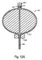
図1Aに目を向けると、図1Aは、本発明に従う第1の移植片20を示している。移植片は、ニチノール等の弾力性のある材料を備える管状ブレード株から形成され、非圧縮/拘束状態で開放容積(概して、円形、球状、卵形、ハート形等)を画定する。 Turning to FIG. 1A, FIG. 1A shows a
移植片20は、血管分岐4にある動脈瘤嚢2内に設定される。移植片は、幹線血管8(例えば、脳底動脈)を通した、好ましくは、以下に記載される通りの送達システムによる、市販のマイクロカテーテル(図示せず)を通したアクセスによって送達される。 The
移植片の大きさは、動脈瘤の頚部10を充填するか、またはそこから幾分外へ延びるように選択されてもよく、そのため、装置の近位端22により、直接血液は、そこから血管枝8へ構築されるブレードの表面に沿って流れることができる。ボールの遠位端はドーム形で、ブレードの襞24に隣接し、その結果、少なくとも動脈瘤の頚部10での流れによって影響を受ける2層26、28(それぞれ内外層)構造となる。示される通り、1巻以上のコイル30(例えば、Ptワイヤ)またはバンド(図示せず)は、移植片の場所の印を付けるように、遠位放射線不透過性特徴を提供してもよい。 The size of the implant may be selected to fill the
ブレードの襞24は、図1Bに示される移植片40において、より目の詰まった半径に設定される。ここで、移植片40は、血管14から離れて側壁動脈瘤12内に受容される。移植片のハブ42は、血管アクセスおよび送達の線からの、およびそれに沿って方向付けられる血液に面している。 The
図2においてより容易に見られる通り、移植片40は、襞によって画定される開口46を閉じるタイ44を含む。放射線不透過性(例えば、Pt)マーカー48は、タイによって担持される。かかるマーカーは、送達用移植片の圧縮に干渉しない。ボールの近位端のX線撮影の可視性は、一緒にまたは単独で来るブレードの密度によって達成されてもよいか、または放射線不透過性(例えば、Pt)バンド50が追加されてもよい。 As can be more easily seen in FIG. 2, the
タイ44は、ステンレス鋼、チタン、ニチノール(場合によっては、一般に“筋肉ワイヤ”と呼ばれる、体温でマルテンサイト(martinistic)であるワイヤ)、縫合糸等を含む、任意の生体適合性材料を備えてもよい。ワイヤを利用する利点は、ワイヤは、マーカーとともにその位置を固定するように、単に湾曲されてもよいことである。いずれの場合も、タイフィラメントは、最小半径の襞が望ましい場合には、薄くなくてはならない(例えば、直径約0.0015インチ以下)。 The
移植片40の別の顕著な特徴は、ハブ42に隣接する区域に関する。具体的には、張り出したまたはトランペット形の再捕捉外形52は、装置がそこを通って前進する送達カテーテルの中への装置再捕捉を助けるように、ブレードの中に設定される。アクセスポート54は、ハブ内に提供される。このポートは、送達システムインターフェースを受け入れる。送達システムの構造だけでなく、移植片のさらなる任意の詳細も、以下で提供される。 Another salient feature of the
当然の流れとして、図2は、非拘束状態にあるボールを示している。動脈瘤内に設定する時に、移植片は代わりに、その形状(例えば、図1Aに示すような)に実質的に一致するであろう。概して、移植片は、ある小さな負荷を動脈瘤壁に及ぼし、ボールの安定位置を維持するのを助けるように、少々特大化されるであろう。しかしながら、いずれのハブの特徴も、血流を追跡するように、ボールと一緒に回転することができるのが望ましい場合、ボールは、特に側壁での用途(例えば、図1Bに示すような)においては、意図的に小振りになってもよい。 As a matter of course, FIG. 2 shows the ball in an unconstrained state. When set within the aneurysm, the implant will instead substantially conform to its shape (eg, as shown in FIG. 1A). In general, the implant will be slightly oversized to help exert a small load on the aneurysm wall and maintain a stable position of the ball. However, if any hub feature is desired to be able to rotate with the ball to track blood flow, the ball is particularly useful in sidewall applications (eg, as shown in FIG. 1B). May be intentionally small.
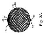
望ましい嵌合に応じて、医師によって選択された移植片は、動脈瘤の形態可変性および/または医用画像の限界のために、送達の時にまさしく正確な大きさであったと判明してもよい。再捕捉外形が、移植片回収を促進することによって、最も有用となるのがその時である。第1の移植片は、より適切な大きさを有する第2のものに有利なように、処分され得る。図3A−3Cは、移植片60、62、および64を大きさの漸次的変化において示している。当然ながら、サイジングの間隔は異なってもよい。同様に、形状も異なってもよい。 Depending on the desired fit, the implant selected by the physician may prove to be exactly the correct size at the time of delivery due to the variability of the aneurysm and / or limitations of the medical image. It is then that the recapture profile is most useful by facilitating graft retrieval. The first implant can be disposed of in favor of a second having a more appropriate size. 3A-
提供される3つの例では、一貫したコアの大きさがボールの中心に対して維持されていることは、注目に値する。概して、コアの大きさ全体を最小化するのが望ましいであろう。しかしながら、ブレード株の所与のチューブを編む時に達成することができるブレードの密度は、その直径およびワイヤの大きさによって制限される。したがって、示される3つのボールの各々は、異なる数のワイヤまたは「縦糸」を組み込むブレードから成る。例えば、第1の移植片62は、直径6mmのマンドレルにわたって編まれる、折り重ねられた72本の材料から生成されてもよく、第2の移植片64は、8mmのマンドレルからの折り重ねられた96本のブレードから成ってもよく、第3の移植片64は、10mmのマンドレル上に作製された、折り重ねられた144本のブレードから成ってもよい。あるいは、より大きな移植片(すなわち、直径でおよそ10mmのもの)もまた、より薄型の交差を維持するために、96本のブレードから成ってもよい。具体的には、0.027インチのカテーテルの交差外形は、直径0.001”のワイヤから成る96本のブレードを使用する時に、達成することができる。同様に、より小さな縦糸の範囲では(例えば、直径およそ5mm)、0.021インチの交差外形を達成するように、代わりに64本のブレードが選択されてもよい。 In the three examples provided, it is noteworthy that a consistent core size is maintained with respect to the center of the ball. In general, it would be desirable to minimize the overall size of the core. However, the density of blades that can be achieved when weaving a given tube of blade stock is limited by its diameter and wire size. Thus, each of the three balls shown consists of a blade that incorporates a different number of wires or “warps”. For example, the
いずれの場合でも、ブレードフィラメントは、これらの移植片、すなわち各層26、28からの移植片内に、組で示される。ブレードの組織がしばしば、より無作為である一方、ブレードの所与の初期直径に対するブレード密度の制限のため、平均的には二重/デュアル層構造が、単一層の移植片と一緒に達成されてもよい、より高い密度をもたらす。 In either case, the blade filaments are shown in pairs within these grafts, ie grafts from each
図4Aおよび4Bに示される移植片70、72もそれぞれ、デュアル層構造であってもよい。その場合、移植片は、先の移植片20/40/60とそれらの遠位構成を共有するであろう。示される通り、移植片は、遠位端が差し込みハブ74の形態を取る、単一層装置である。 Each of the
どちらにしても、移植片は、独特な近位端構成を含む。ボールまたは球根状部分80に加えて、各移植片は、その血流破壊の可能性を改善するように意図される、皮弁76、78を含む。移植片70に含まれる皮弁76は、動脈瘤(anerusmal)内での使用を意図している。示す通り、移植片を送達するために、ボールまたは球根状部分が最初、動脈瘤嚢2の中へ送達される。それから、装置のその部分は、その中に皮弁を配備するように、押込器100にまだ載置される間に、圧縮される。図4aに示す通りに最終位置付けが達成された後、それからハブ42内に受容される押込器係止部材が解放される。最後に、押込器は、送達カテーテル110の中へ回収される。送達方法を補助するために、1つ以上のさらなる放射線不透過性特徴(ボール部80の近位端にあるバンド50等)が、配備を各段階で可視化することができるように提供されてもよい。 Either way, the implant includes a unique proximal end configuration. In addition to the ball or
図4Bの移植片は、送達においてかかる複雑さは必要としない。皮弁78は、動脈瘤頚部を充填するようにのみ選択された大きさから成るため、移植片はすぐに送達することができる。また、適切な嵌合および/または配備を確認するのに、中間放射線不透過性特徴が望ましい場合がある。 The implant of FIG. 4B does not require such complexity in delivery. Because the flap 78 is of a size selected only to fill the aneurysm neck, the implant can be delivered immediately. Also, intermediate radiopaque features may be desirable to confirm proper mating and / or deployment.
描かれている通り、図4Bに示される移植片のボールおよびディスクの変形例は、図4Aの“ドングリ”型変形例と比較して、より小さな頚部動脈瘤に適するのみでもよい。概して、ディスクの大きさは、親/幹線血管6の直径および/または分岐区域4の大きさより著しく大きくはないであろう。それ以外の場合には、脈管構造は配備に干渉するであろう。したがって、ディスクは、直径約2.5mmから約5mmに制限されてもよい。 As depicted, the graft ball and disk variation shown in FIG. 4B may only be suitable for smaller cervical aneurysms compared to the “acorn” type variation of FIG. 4A. In general, the size of the disc will not be significantly greater than the diameter of the parent /
以下の移植片製造段階の文脈をより良く理解する一方で、皮弁78は、その上方でブレードが熱固定される単純な座金またはプレートを使用して、形成されてもよい。それ以外の場合には、形成道具は、皮弁78が主要移植片本体の輪郭により良く従うように、曲がっているか、またはくぼんでいてもよい。 While better understanding the context of the following graft manufacturing stage, the flap 78 may be formed using a simple washer or plate over which the blade is heat set. Otherwise, the forming tool may be bent or recessed so that the flap 78 better follows the contours of the main graft body.
図4Aの変形例の皮弁76は、通常、類似の様式で凹面/凸面形態を使用して形成されるであろう。この皮弁の大きさは異なってよい。示される通り、その外側の広がりは、おおよそ装置のボール部分80の直径と同一である。それはより小さくてもよく、および/または移植片70の近位側のより小さな広がりを被覆してもよい。概して、皮弁70は、本体80の少なくとも約3分の1、および2分の1と同程度を被覆するであろう。このように、適当な頚部の被覆範囲は、広い頚部動脈瘤を治療するように用いられる時に、より保証される。 The
図5Aは、ブレードボール移植片のステント固着版の側面図である。ステント120は、末端動脈瘤を治療する時に、幹線血管の中で固着する大きさである。このように、ボール部分122は、その容積全体の代わりに、動脈瘤の頚部を充填するのみの大きさであってもよい。かかる方法は、普通見られることが少ない形状の動脈瘤に対して特に有用である場合がある。図5Bの装置は、ブレードボール移植片がフレームまたはケージ124によって導入および担持される以外で、ステント部が定位置に設定された後に、類似の様式で使用される。 FIG. 5A is a side view of a stented version of a blade ball graft. The
フレームは、ハブ128に固定され、/近位端および別のハブにあるステント、または遠位端にあるパターン130の複数の個別ワイヤ126を備えてもよい。別の変形例では、フレームを構成するワイヤは、ステントセルおよび任意の含まれるハブと同一のチューブから切り取られる。ワイヤは、ハブ内の遠位端で終端するか、放射線不透過性バンド内で加締められるか、共に溶接されるか、接着剤によって固定されるか、または幾つかの他の手段によって取り付けられてもよい。いずれの場合も、ワイヤは、通常(必ずしもではないが)、閉じたフレームを形成するように取り付けられる。なお、開放フレームも、特にワイヤが、配置された時にボールを「捕獲する」のを助けるように、後方へ(すなわち、近位に)掛止するものが、熟慮される。 The frame may comprise a plurality of
これらの装置(すなわち、図5Aおよび5Bに示されるもの)は、“反跳躍”/回収特徴がステント部の中に組み込まれてもよい以外は、標準的な技術を用いて送達される。それにもかかわらず、少なくとも1列のステントセル132は、最小水準の固着を引き起こすように、ステントの中に提供されるが、しかしながら、5つまたはそれ以上の数のものが、任意の特別な送達反跳躍/制御特徴有りまたはなしで、用いられてもよい。 These devices (ie, those shown in FIGS. 5A and 5B) are delivered using standard techniques, except that “recoil” / recovery features may be incorporated into the stent section. Nevertheless, at least one row of
ステントが有利に、ボールまたはボールケージ用の3つの支持拡張部134を含む一方で、多いまたは少ない数が用いられてもよい。しかしながら、3つを使用することにより、利用可能な最小の安定構造が提供される。そして、3つが一緒になると、それらは、端に載置されたボール/フレームが、治療される動脈瘤への干渉に成功できるように、正に自在継ぎ手のように動作する。 While the stent advantageously includes three support extensions 134 for the ball or ball cage, a greater or lesser number may be used. However, using the three provides the smallest stable structure available. And when the three come together, they act just like a universal joint so that the ball / frame placed on the end can successfully interfere with the aneurysm being treated.
図6は、主題の移植片の全く異なる使用を示している。すなわち、移植片140は、流れを閉塞させるように、血管に(動脈瘤内の血管に隣接するのに対して)配備される。上述の通り、PVO使用に対して、ボールの遠位端は、結節またはニップル142を含んでもよい。実際、かかる特徴は、図7に示す通り、構造において有利である。 FIG. 6 shows a completely different use of the subject implant. That is, the
この側面断面図では、ブレードマトリクスは、襞24で反転(または裏返し)して示されている。バンド144は、内側および外側ブレード層間に設定される。バンドは端部を閉じ、マーカー(特にそれがPtを備える時)として機能する。接着剤146(例えば、LOCTITE3311または4014)は、襞開口内の任意の残留管腔を充填するように、使用されてもよい。他の移植片(図4Aおよび4Bの移植片を含む)と同様に、移植片は、ハブ42に隣接して、その近位端に再捕捉外形部52を含んでもよい。同様に、ハブポート54を含んでもよい。 In this side cross-sectional view, the blade matrix is shown flipped (or flipped) with
それ以外の場合、移植片の両端は、接着剤または別の方法で、閉じて/塞いでもよい。送達システムのアクセスポートがない場合、移植片は、単純な押込器を使用して(完全に回収可能および/または再位置付け可能であるのに対して)、送達されてもよい。このように構成されると、近位ハブも必要とされない。実際、ブレードは、単に切り取られ、一緒になるように形状設定してもよく、および/または溶接、接着剤、またはその他の方法で近位端に固定されてもよい。 Otherwise, both ends of the implant may be closed / occluded with an adhesive or otherwise. In the absence of an access port for the delivery system, the implant may be delivered using a simple pusher (as opposed to being fully recoverable and / or repositionable). When configured in this way, a proximal hub is also not required. In fact, the blades may simply be cut and shaped together and / or secured to the proximal end by welding, adhesive, or other methods.
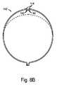
本発明の別の任意局面が、図8Aおよび8Bに示されている。すなわち、折り畳み層移植片140は最初、ブレード襞24の曲げ半径を最小化するステップを取ることなく形成される。まだ使用可能である間に、図8Bに示す通り、修正された移植片140’を生成するように、折り畳み層を切り取ることが、その代わりに望ましい場合がある。そうすることで、バルクは排除され、ある状況において望ましい場合があるように、移植片の送達特質も変更される。ブレードの端部142が底入れよりむしろ、相互に通り過ぎることができるため、移植片はより半径方向に従順となり、より広範な動脈瘤の大きさに嵌合することができる。したがって、同一の移植片140’は、図8Bにおいてダッシュで示された動脈瘤の頚部から必ずしも延びることなく、より小さな容積を充填することができる。 Another optional aspect of the present invention is illustrated in FIGS. 8A and 8B. That is, the
いずれの場合にも、2層を生成するように、ブレードの1本のチューブを利用し折り重ねる、元の構造技術によって、(現在分離された)層は、予想通りに拡張および収縮するようによく合致する。その上、任意の外形を制限する屈曲が除去される(例えば、切断、研削等によって)と、上記の適応性特徴が望ましくない場合には、層は再接続することができる。ウレタンコーティング層144または他の接着剤(有利には、放射線不透過性バリウムまたはタンタル粉を含む)は、送達外形を増大させる結果とならなくとも、かかる作用を実現するように、局所的に使用されてもよい。 In either case, the layers (currently separated) expand and contract as expected by the original construction technique, which utilizes one tube of the blade and folds to produce two layers. Matches well. Moreover, once the bends that limit any profile are removed (eg, by cutting, grinding, etc.), the layers can be reconnected if the above adaptive features are not desired.
また、移植片に襞を維持することは、他の状況において、特に、襞がワイヤの曲げ半径/外形を最小化するような方式で形成される時、数々の利点を提供する。すなわち、襞を含む移植片は、望ましい時は状況においてより良い大きさの統合および半径方向力を提供し、さらに処理をする(ポリマー利用によって等)ことなく移植片の端部で任意の緩んだ繊維を排除し、マーカーにポケットを提供し、および/またはマーカーを吊り下げるように結びつける等してもよい。 Also, maintaining the plication on the graft provides numerous advantages in other situations, particularly when the plication is formed in a manner that minimizes the bend radius / outline of the wire. That is, the graft containing the plication provides better sized integration and radial force in the situation when desired, and any loosening at the end of the graft without further processing (such as by using a polymer) The fibers may be eliminated, the marker may be provided with a pocket, and / or the marker may be tied to hang, etc.
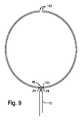
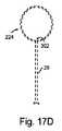
その上、移植片の折り畳まれた端部が、装置の遠位端に必ずしも設定されないであろうことは、認識されるべきである。むしろ、折り畳み部24は、図9に示される通り、近位側で利用されてもよい。そして、折り畳み部によって形成される開口46(リング、バンド、またはタイ150によって担持される時)は、送達システム110のインターフェースを提供する。移植片の対向端は、差し込みハブ(例えば、図4Aおよび4Bに示す通り)を有するか、あるいは図8Bに示される(組み込みポリマー有りまたはなし)ものと非常に似ているか、またはその他の方法で構成された、切り取られた端部142で終端してもよい。 Moreover, it should be appreciated that the folded end of the implant will not necessarily be set at the distal end of the device. Rather, the
いずれの場合でも、図10A−10Dは、襞の外形が最小化される、折り畳み部移植片を構築する1つの方法を示している。当業者によって理解されるであろう通り、方法の要素は、本願に記載の様々な移植片の構成に適用されてもよい。 In any case, FIGS. 10A-10D illustrate one method of constructing a fold graft in which the profile of the fold is minimized. As will be appreciated by those skilled in the art, method elements may be applied to the various implant configurations described herein.
これらの図において、図10Aは、マンドレル204上で縫合部202と結び付けられる、ブレード200の一部分を示している。タイは、10Bに示される通り、ブレードが反転する時に、外層28が内層26を過ぎて延びるように、ブレードが切り取られる所からずれる。緩い襞210が展開され、ブレードは形態212を形作る移植片を囲んでいる。 In these figures, FIG. 10A shows a portion of the
図10Cでは、ブレードは、ボール形態212の周囲にあるラップ214(通常、Ptまたはステンレス鋼ワイヤ)によって伸展および固定される。圧縮形態216、218もまた示されている(矢印によって示される通り、固定によって担持される)。襞側の形態216は、熱固定の間(例えば、ニチノールブレードに対しては550℃で5分間)に、襞を最小外形にまで圧縮される。このプロセスにおいて、元のタイ202(縫合から構成される場合)は、ゼロまたはゼロ付近で襞の半径の曲げを達成するため、いずれの障害を除去して、燃え尽きる。正対形態218は、尖った段部を画定してもよく(ボールのその端部が、以下に記載される通りの“浮遊層”ボールの中で、遠位端として切り取られ使用されるべき時等)、または再捕捉外形をブレードへと形作ってもよい。 In FIG. 10C, the blade is extended and secured by a wrap 214 (usually Pt or stainless steel wire) around the
任意のかかる形状設定の後、装置機能部220は、内部形態が最終的に図10Dに示される通りに除去されるとすぐに準備が整う。このプロセスの間、ブレードの端部は開放へと付勢され、通常ブレード統合/係合を失う。かかる作用は移植片統合に悪影響を与えないため、機能部220に組み込まれる“尾”220は、移植片の意図される本体224に影響を与える、ほどかれたブレード端部からの任意の損傷を避けるよう、十分に長くなくてはならない(すなわち、しばしば約2cm以上)。 After any such shape setting, the
移植片が、酸化被膜を含むブレードから形成される場合、機能部は次にエッチングされ、それから不動態化される。しかしながら、事前にエッチングされたワイヤが、塩鍋の中で、真空炉の中で、または酸化物形成を最小化する他の機器を使用して実行される、ブレイディングおよぶ任意の熱固定で使用される場合、機能部により、硝酸不動態化の影響を簡単に受けやすい場合がある。 If the implant is formed from a blade that includes an oxide coating, the feature is then etched and then passivated. However, pre-etched wires are used in braiding and any heat setting, performed in salt pans, in vacuum furnaces, or using other equipment that minimizes oxide formation In some cases, the functional part may be easily affected by nitric acid passivation.
用いられるさらなる中間プロセスのステップにおいてさえ、図10Eは、バンド50がハブを形成するのに追加されてもよい様式を示している。具体的には、外層28をラップ226と結びつけた後、バンドは、この部分を越えて通されてもよい。真下に内層なしの場合、結び付けられた部分228は、バンドが、移植片本体224に隣接する地点まで前進する時に、ブレードの両方の層(および任意のマンドレル230、その実用性は下で議論される)の周囲に緊密に嵌合する大きさであることができるように、バンド50内に嵌合する。 Even in the further intermediate process steps used, FIG. 10E shows the manner in which the
履行の間に襞を圧縮形成する代替法として、ブレードワイヤの曲げを最小半径で達成する形状形成が、図11Aおよび11Bに表される。これらの図は、移植片の襞の形状を事前設定するための技術を示している。図11Aでは、クリンパー装置(例えば、Machine Solutions, Inc.等により市販されるような)の楔240は、複数の屈曲を画定するように折り重ねられるブレード200を受容する。マンドレル242は、ブレードの内部に有利に設定される。マンドレルは、楔によって形成される開口244が、図11Bに示す通り閉じられる時に、曲げ半径をきつくすることが必要とされ、ブレードチューブの圧縮を制限する。襞の形状は、熱ならびに/または歪みおよび熱の組み合わせによって設定される。熱は、トーチによって、炉内で、または好都合にはマンドレルを通る発生中の電流によって、加えられてもよい。別の方法では、複数要素のチャックまたはコレット型装置が、上に示されるクリンパーの楔に対し、類似の様式で用いられる。 As an alternative to compression forming the heel during implementation, a shape formation that achieves a minimum bending radius of the blade wire is depicted in FIGS. 11A and 11B. These figures illustrate a technique for pre-setting the shape of the graft plication. In FIG. 11A, a
そのように形成されると、移植片全体は、縫合タイの使用または216への圧縮なしで、図10A−10Dとの関係で記載される通りに、大部分が形成されてもよい。代わりに、プロセスの間中残っている恒久的に優れたワイヤタイは、ボールの折り畳まれた端部を閉じるように用いられてもよい。このタイは、屈曲を曝露するように、折り畳まれたブレードをめくることによってのみ、取り付けることができる。あるいは、タイは、針付きの屈曲襞を通ってその周囲に進められ、結びつくことができる。 When so formed, the entire implant may be largely formed as described in relation to FIGS. 10A-10D without the use of suture ties or compression to 216. Alternatively, a permanently superior wire tie that remains throughout the process may be used to close the folded end of the ball. The tie can only be attached by flipping the folded blade to expose the bend. Alternatively, the tie can be advanced and tied around the bend with a needle.
移植片のバルクを熱固定する間に、襞または襞を形成する圧縮を事前に処理することは、襞に隣接する区域がドーム形であるべきそれらの場合に対して、特に有利である。しかしながら、小塊が、その意図的使用(例えば、PVO)のために与えられた装置設計において許容可能である時には、図12Aおよび12Bは、別の方法を示す。具体的には、ハイポチューブ250(またはポケットを含む、他の形状形態)は、ブレードにわたって配置され、ブレードは示される通り、バンド50ならびに/またはバンドおよびマンドレル204の間に閉じ込められる。加えて、図12Bに示される通り、第2のハイポチューブ252(または形状ポケットの中の表面)は、正確な形状設定のため、ブレードをさらに拘束するように、遠位屈曲点254に隣接することができる。 It is particularly advantageous for those cases where the area adjacent to the fold to be dome-shaped to pre-treat the crease or the compression that forms the fold while heat-fixing the bulk of the implant. However, when the blob is acceptable in a given device design for its intended use (eg, PVO), FIGS. 12A and 12B show another method. Specifically, a hypotube 250 (or other shape, including a pocket) is placed over the blade, and the blade is confined between the
移植片またはその機能部220の残っている形状の設定に関しては、図12Aが、円滑な再捕捉外形を設定するように、近位トランペット形状形態256の使用を示している。図12Bにおいて、近位形状258は、目の詰まったまたは尖った半径を設定する。かかる形状は、より大きな局所の屈曲する歪みによって、移植片においてより高い半径方向力を達成するように望まれてもよい。 With respect to setting the remaining shape of the implant or its
図12Bに示される移植片は、図面に示される他の注目すべき特徴によって、図12Aの移植片にわたる固着の改善を達成しようとする。すなわち、その他の卵形装置形状に沿って、移植片に設定される円筒形バンド260形状は、固着を向上させるように、局所応力を増加させながら、血管組織と相互作用する端部262を生成する。 The implant shown in FIG. 12B seeks to achieve improved adhesion over the implant of FIG. 12A by other notable features shown in the drawing. That is, along with other oval device shapes, the
両方の移植片はまだ、前に描いた球面ボール移植片に対する、扁平/減少アスペクト比を共有する。かかるアスペクト比により、装置のその結果得られた長さに対して、血管の中に自己拡張する移植片を固着するための、より大きな特大化が許容される。PVO用途で隣接する穿通枝(perferorator)/血管枝が不注意に遮断されるため、閉塞の焦点距離がしばしば、神経血管障害を治療するのに重要であることが、この事実の有利な前提となっている。 Both implants still share a flat / decreasing aspect ratio relative to the previously drawn spherical ball implant. Such an aspect ratio allows for a larger oversize to secure the self-expanding graft into the blood vessel for the resulting length of the device. The premise of this fact is that the focal length of the occlusion is often important for treating neurovascular disorders, as the adjacent perforator / vessel branch is inadvertently blocked in PVO applications It has become.
移植片の形態が何であろうとも、ハブがブレードフィラメントを固定するように含まれている時には、ある添加に関する困難に対処しなくてはならない。ハブは、ブレードにしっかりと締結されなくてはならず、特徴の長さを最小化する必要がある場合がある。図13Aおよび13Bは、代替のブレード/バンド添加法を示す、部分側面断面図である。図13Aでは、バンド50は、ブレード用の切り取り線を越えて設定される。その結果生じる小さな尾270は、糊272を塗ることができる表面を提供する。硬化すると(例えば、UV用途により)、接着剤はブレードに混入され、バンドが通過できない端部274を形成する。糊が使用されない場合、その時ブレードは、バンド用の干渉特徴を類似して形成するように、レーザで溶解されてもよい。かかるレーザの利用により、用いられる場合には、ブレードを内部バンド276に溶接してもよい。レーザは、ブレード周辺に半径方向に、またはブレードの切り取り面にわたって軸方向に適用されてもよい。 Whatever the morphology of the graft, difficulties with certain additions must be addressed when the hub is included to secure the blade filament. The hub must be securely fastened to the blade and the feature length may need to be minimized. 13A and 13B are partial side cross-sectional views illustrating an alternative blade / band addition method. In FIG. 13A, the
特に、レーザエネルギーを利用する時には、図13Bに示されているような代替法が用いられてもよい。ここでは、バンドの端部およびブレード面にわたって軸方向に向けられたレーザエネルギーを適用することによって、これらの全てが共に溶接されてもよい。そのように溶接される場合、その結果生じる面は、ポリマー接着剤272で密封されてもよい。 In particular, when utilizing laser energy, an alternative method as shown in FIG. 13B may be used. Here, all of these may be welded together by applying laser energy directed axially across the end of the band and the blade face. When so welded, the resulting surface may be sealed with a
図14は、さらに別のハブ固定法を示している。ここで浸潤は、結合を形成するために、バンドの下のブレードを通る糊/接着剤貫通として、信頼されている。糊の玉280は、バンド50に隣接するブレード200の露出したセグメントに塗布される。棒状ではない(例えば、PTFEでコーティングされた)マンドレル230は、糊で含浸されたブレード内で管腔を正確に画定するように、ブレード内部に位置してもよい。管腔は、送達システムポートとして有利に動作する。接着剤が硬化し、マンドレルが除去されると、正確な大きさの複合壁構造が生成される。 FIG. 14 shows yet another hub fixing method. Here infiltration is trusted as glue / adhesive penetration through the blade under the band to form a bond. A ball of
接着剤は、示される通り、アセンブリを回転させることによって、ブレードの周囲に均等に塗布されてもよい。他の方法が利用されてもよい。1つのかかる方法では、複数の任意のアクセスウィンドウ282が、接着剤を受容および撒布するように、バンドの中に含まれてもよい。接着剤もまた任意で、ブレード管腔の被覆範囲および/またはバンド50の接着を保証するように利用される浸潤/流動接着剤の任意の過剰も、移植片本体224の自己拡張作用に干渉しないように、紙のカードまたは吸収性繊維パッド284(または他の手段によって除去)によって、ブレード200から離れて浸潤される。 The adhesive may be applied evenly around the blade by rotating the assembly as shown. Other methods may be used. In one such method, a plurality of
内側バンド276の使用もまた任意である。内側バンドがブレードとのりのみの管腔が保存する空間を占有する間、ハブアセンブリ42に内側バンドを含むことは、時に剥離システムインターフェースとして望ましい場合がある。 The use of
補助ハイポチューブ286の使用もまた任意である。しかしながら、このチューブは、続く切り取りのためにその上を留める、有用な取っ手またはハンドルを提供する。特にかかる使用には、チューブが得るであろうさらなる安定性から、壁の厚い(例えば、約0.005”以上)チューブが望ましい場合がある。移植片の一部となるバンドと同様に、ハイポチューブ286は、接着剤の塗布のための1つ以上のアクセスウィンドウ282を含んでもよい。 The use of an
移植片機能部220を切り取るために(しかしながら、それは形作られるが)、図15は、図14に示されるハブ固定法とよく協調する方法を示している。具体的には、補助ハイポチューブは、スライド292上に載置される固定具290の中に捕捉される。バンドおよびハイポチューブ286の取っ手の間に確立される隙間296と、鋸刃294(通常、0.004−0.010インチのダイヤモンドでコーティングされたホイール)を並べるために、横の調整が提供されてもよい。並べられると(切り取り線が隙間にあってもよく、またはバンド自体が切り落とされてもよい)、移植片は切り落とされる。処理に役立つように、移植片は、示される通り外筒298の中で、少なくとも部分的に拘束されてもよい。正確な切断/切り取りにより、高さ約0.010インチほどの短いバンド(切り取られるか、または最初に組み立てられるような)が可能になる。しかしながら、より控えめな大きさ(例えば、高さ約0.020インチ)が、ブレード捕捉および剥離システムの頑強さを保証するのに望ましい場合もある。 In order to trim the graft feature 220 (but it is shaped), FIG. 15 illustrates a method that works well with the hub anchoring method shown in FIG. Specifically, the auxiliary hypotube is captured in a fixture 290 that is mounted on a
切断が行われた後、ハブの長さは、その面を研削することによって、さらに短縮されてもよい。マンドレルの除去(切り取り処置における切り落としも)および超音波浴槽内での洗浄の後、ハブ面は接着剤で密封されてもよい。 After the cut is made, the length of the hub may be further shortened by grinding the surface. After removal of the mandrels (also cut off in the cutting procedure) and cleaning in the ultrasonic bath, the hub surface may be sealed with an adhesive.
前述のハブ技術のいずれかを使用して生成され、別の移植片変形例300が、図16に示されている。その製造に対して更なる独特なステップが、図17A−17Dに表される。 Another
移植片は、装置の各端部で固定されないブレードの層を含む点で、上記のものと異なる。むしろ、内層26は浮遊している。その存在により移植片の密度は増大するが、ハブ42に隣接するその繊維は、ボールが送達および/または再捕捉のために外筒の中に圧縮される時に、曲がるように付勢されない。したがって、ブレードがハブから退出すると、およそ90度で曲げられる時でさえ(すなわち、設計における再捕捉外形を含む移植片本体224の近位端なしで)、比較的小さな力が必要となる。 The implant differs from that described above in that it includes a layer of blade that is not secured at each end of the device. Rather, the
外部ブレードの密度が最も高く、その密度により、ブレードマトリクスから突き出る内層からの、個々のフィラメントを最もよく妨げることができるハブに近接する、内部ブレード端部302付きのボールを生成するために、製造ステップのうちの的確なセットが実行される。具体的には、図17Aに示される通り、移植片機能部220から開始した後、ブレードの外層は、図17Bに示す通り、移植片の意図された本体224から引っぱられるか、または押して外される。ブレードの内層は、図17Cに示す通り切り取られる。ワイヤカッター、はさみ、または他の手段が用いられてもよい。最後に、図17Dに示す通り、外層がその元の位置に戻され、移植片機能部がさらに処理される。 Manufactured to produce a ball with an
かかるさらなるプロセスは、閉じられた襞の開口を縛る/ハブにする、切り取りおよび/または結ぶステップを含んでもよい。しかしながら、かかる縛るステップは、襞24が図17B/17Cごとに露出されている間に、外側ブレードの位置を回復する前に実行されると好都合である場合がある。 Such additional processes may include cutting and / or tying, tying / hubing closed fold openings. However, such a tying step may be conveniently performed prior to restoring the position of the outer blade while the
どんな技術がそれらの構造に用いられようとも、移植片は、解放可能な押込器に有利に載置される。図18の送達システム310は、切り取りウィンドウ314付きハイポチューブシャフト312を含む。ボールハブに隣接するウィンドウ312は非常に重要であり、他のウィンドウは単に有利なものある。コア部材316(有利には、ニチノールリボン)は、近位ウィンドウ312または切り取りから退出し、第2の314で再進入する。ハイポチューブに取り付けられる段部/緩衝器316は、移植片40を押すように、ハブ50の近位端に隣接する。あるいは、ハイポチューブから送達システム張力緩和部318および/またはハブ320までの長さへ伸びる外部スリーブ(図示せず)が提供されてもよい。移植片を送達カテーテル(図示せず)の中へ収縮させるのを可能にするために、コア部材316は、移植片を保持するように、ハブ管腔(非表示)の内側表面に係合する。 Whatever technique is used for these structures, the implant is advantageously placed in a releasable pusher. The delivery system 310 of FIG. 18 includes a
解放を可能にするために、コア部材は、つまみ322を引っぱることによって、各々のウィンドウ312、314を消去するハイポチューブ310の中へ回収される。この時点で、ハイポチューブは、押込器を回収することによって、ハブポート54から退出してもよい。 To allow release, the core member is collected into the hypotube 310 that erases each
別の取り外し可能な送達システム330が、図19Aおよび19Bに示されている。システムは、制御ワイヤ332が、固着ワイヤ336上に載置される頭部334の干渉を解放するように引っぱられる、完全な同軸設計であり、それでなければハブポートまたは管腔54を通過できない。ワイヤが真っ直ぐ外へ引っぱられ、干渉を保証するように、固着ワイヤ頭部を位置付けるのみであるため(図19Bに明確に図示)、最小限の努力のみが必要とされる。少なくとも制御ワイヤを覆うEPTFEコーティングも有用である。 Another
制御ワイヤ332は、固着ワイヤ頭部334にまで、またはそこを越えて延びてもよい(図19Aに示されているのが前者の場合)。別の選択肢は、制御ワイヤの長さを、任意の内側バンド276または全体ハブ42の高さの寸法に制限することである(図19Bに示す通り)。図19Aは、押込器スリーブ338および移植片ハブ50の間の隙間を示していることにも注目すべきであろう。この描写は、図解の説明のためだけのものである。 The
いずれの場合も、押込器スリーブ管腔340および移植片ハブ管腔/ポート52の各々は、好ましくは、ワイヤ(制御ワイヤ332および固着ワイヤ336)が密集配列で受容されるような大きさである。このような態様で、移植片および押込器スリーブは、編まれるかまたは絡み合うワイヤに関連する、搭載問題を排除するガイドとして機能する。またシステムを搭載するために、固着ワイヤは通常、移植片および押込器の間の任意の隙間も閉じられ、使用中は閉じたままであることを保証するように、ほんのわずかな度合いで張力をかけられる(ハンドルの中に簡単な糊付けを行うか、またはハンドル設計に組み込まれたバイアスばねを使用する前に)。 In any case, each of the
図20A−20Fは、使用される送達システム330の変形例を示している。剥離システムの遠位端は、移植片のハブ42部分と一緒に示されている。図20Aは、係合される押込器連動装置を示す。図20B−20Dは、制御ワイヤ332の連続して起こる回収を示している。固着ワイヤ336もまた、図20Eに示される通り、個々に回収されてもよい。しかしながら、代わりに、剥離システムスリーブ338と一緒に回収されてもよい。実際には、スリーブに添付されてもよい。またさらに、制御ワイヤは1つずつ引っぱられる必要はないことは理解されるべきである。一緒に起動させることもできる。いずれの場合も、完全な移植片の分離が、図20Fに示されている。 20A-20F show a variation of the
最後に、図21は、移植片342およびハンドル342を含む、治療システム340の概要を表している。これらのうちの1つ、または両方のいずれかが、本願の教示に従い構築されてもよい。示されるハンドル342は、3つのノブを含む。1つのノブ344は、制御ワイヤ(視野からは非表示)に、最後のノブ346は固着ワイヤ(視野からは非表示)に接続する。取り外し可能な係止キャップ348は、ハンドル設計だけでなく、張力緩和部350にも含まれてもよい。カテーテル/押込器シャフト338は、単純な突出(例えば、PTFE、FEP、PEEK等)を備えてもよいか、または従来のカテーテル構造技術を使用して構築され、ライナー、ブレード支持部、および外部ジャケット(図示せず)を含んでもよい。搭載外筒352は通常、押込器シャフトにわたって提供される。有利なことに、搭載外筒はモデルが示される通り、分割可能である。 Finally, FIG. 21 represents an overview of a
無菌包装(図示せず)からの除去後、移植片は搭載外筒350の中へ引っ張られる。搭載外筒は、移植片送達のために使用されるように、カテーテルのハブ内で受容され、移植片はカテーテルの中へ前進する。それから、移植片は治療部位へ前進し、そこに配備されてもよい。または、別の大きさの移植片と交換で回収されるか、さもなければ、図20A−20Fに示されるもののように、最終剥離の前に、必要に応じて再位置付けされてもよい。 After removal from the sterile packaging (not shown), the implant is pulled into the mounting
主題の方法は、移植片の位置付けおよび解放に関連する医師の活動の各々を含んでもよい。したがって、移植片装置の位置付けおよび配備の暗黙の方法論は、本発明の一部を形成する。かかる方法論は、閉塞または他の用途のために標的とされる脳の動脈瘤内あるいは親血管に、移植片を配置するステップを含んでもよい。方法の中には、動脈瘤または親血管への移植片の導入という様々な行為を考慮するものもある。 The subject method may include each of the physician's activities related to implant positioning and release. Thus, the implicit methodology of implant device positioning and deployment forms part of the present invention. Such methodologies may include placing the graft within a cerebral aneurysm or a parent vessel targeted for occlusion or other applications. Some methods allow for various actions, such as introducing an aneurysm or graft into a parent vessel.
より詳細には、本発明に従う幾つかの方法は、例えば、送達システムが治療部位に到達する時に動作する様式に関する。他の方法は、システムが移植片を送達する、例えば、ブレードボールを送達システムに取り付けるのに備える様式に関する。本願のいずれの方法も、論理的に可能である、列挙された事象のうちの任意の順序だけでなく、事象の列挙された順序、あるいはそれら事象または事象の順序をわずかに改変して実行されてもよい。 More particularly, some methods according to the invention relate to a manner that operates, for example, when a delivery system reaches a treatment site. Another method relates to the manner in which the system provides for delivering an implant, eg, for attaching a blade ball to a delivery system. Any of the methods of this application may be performed with minor modifications to the listed order of events, or the order of events or events, as well as any sequence of listed events that is logically possible. May be.
また、記載された本発明の変形例の任意の随意の特徴は、個々に、または本願に記載された特徴のうちのいずれか1つ以上と組み合わせて、記載され主張されてもよいことは、熟慮されるものとする。単独品目についての言及は、複数の同一品目が存在する可能性を含む。より具体的には、本願および添付の請求項で使用される通り、「1つの(a)」、「1つの(an)」、「前記(said)」、および「その(the)」の単数形は、特に言及されていない限り、複数の指示対象を含む。言い換えると、冠詞の使用により、上の記述だけでなく以下の請求項において、対象品目の「少なくとも1つ」が認められる。なおさらに、請求項は、任意の随意的な要素を除外するように起案されてもよい。したがって、本記載は、「単なる」「唯一の」等の排他的な用語およびその類義語を、列挙された請求項要素と関連づけながら使用することや「否定的な」制限を使用することについて、前もってその理由を提示するものとして意図されている。 Also, any optional feature of the described variations of the invention may be described and claimed individually or in combination with any one or more of the features described herein. Considered. Reference to a single item includes the possibility of multiple identical items. More specifically, as used herein and in the appended claims, the singular of “a”, “an”, “said”, and “the” A shape includes a plurality of indicating objects unless otherwise stated. In other words, the use of the article allows for “at least one” of the subject items, not only in the above description, but also in the following claims. Still further, the claims may be drafted to exclude any optional element. Accordingly, this description provides for the use of exclusive terms such as “simply” and “sole” and their synonyms in connection with the recited claim elements and the use of “negative” restrictions. It is intended to present the reason.
かかる排他的な用語を使用することなく、請求項における用語「備える」は、要素の所与の数字が請求項に列挙されているか、または特徴の追加が、請求項に記載の要素の本質を変形するとみなされ得るかにかかわらず、任意のさらなる要素の包含を許容するものとする。本願で具体的に画定される以外は、全ての技術および科学用語は、請求項の効力を維持しつつ、通常理解される意味をできる限り広範に与えられるものとする。 Without the use of such exclusive terms, the term “comprising” in a claim means that a given number of elements is listed in the claim or that the addition of a feature dictates the essence of the element in the claim. The inclusion of any further elements shall be allowed regardless of whether they can be considered to be deformed. Except as specifically defined herein, all technical and scientific terms are intended to be given the broadest possible meaning as commonly understood while maintaining the effect of the claims.
本発明の範囲は、提供される例および/または対象の明細書に限定するものではないが、請求項の言葉の範囲によってのみ限定される。本願での用語「発明」の使用は、いかなる態様においても請求項の範囲を限定することは意図していない。むしろ、「発明」は、本明細書を読むと当業者には明らかであろうそれらの変形を含み、本願に明示的または黙示的に記載される多くの変形を含むことは、理解されるべきである。さらに、本明細書の任意のセクション(例えば、開示、詳細な説明、要約、背景技術)も、別の発明または請求項に関連して本発明を説明するのに、特別な意味を与えられることを意図していない。列挙された全ての参考文献は、その全体が本明細書に参考として援用される。前述の発明について、理解を明確にするために詳細を説明してきたが、一定の改変が添付の請求項の範囲内で実行されてもよいことが企図される。 The scope of the invention is not limited to the examples provided and / or the subject specification, but is limited only by the scope of the words of the claims. The use of the term “invention” in this application is not intended to limit the scope of the claims in any way. Rather, it should be understood that the "invention" includes those variations that will be apparent to those of ordinary skill in the art upon reading this specification, and includes many variations that are expressly or implicitly set forth herein. It is. Moreover, any section of the specification (eg, disclosure, detailed description, abstract, background art) may be given special meaning to describe the invention in connection with another invention or claim. Not intended. All listed references are incorporated herein by reference in their entirety. Although the foregoing invention has been described in detail for purposes of clarity of understanding, it is contemplated that certain modifications may be practiced within the scope of the appended claims.
Claims (25)
Translated fromJapanese内外層を形成するブレード材料の単一の連続部分を含むブレードであって、該層は、カテーテルを通した送達のために圧縮されるように適応され、かつ拘束から解放されると開放容積に拡張するように適応され、該内外層は、(i)該装置の一方の端部にある折り畳みエッジにおいて互いに接合されており、該折り畳みエッジにおいて、該ブレードが、該開放容積から外向きに折り畳まれ、ここで、該外向きに折り畳まれたブレードの部分が外層を形成しており、(ii)ハブにおいて合流し、ここで、該ハブは該装置の他方の端部において少なくとも該外側ブレード層を担持する、ブレードを備える、装置。An embolic device,
A bladecomprising a single continuous portion of the blade material forming the inner and outer layers, said layerbeing adapted to be compressed for delivery through a catheter andinto theopen volume be released from a constrained is adapted to extend, inner outer layer, (i)are joined together at one end nearRu foldingedge of thedevice, in said folded edges, said blades, outwardly from said open volume folded, wherein the portion of the folded blades in the outer direction forms an outer layer, (ii)merge at the hub, wherein the hubOite least said the other end of the deviceyou carrying an outer braid layer comprises a blade, device.
管状ブレードの第1の部分を該ブレードの第2の部分上または該第2の部分内に反転させ、それにより、該ブレードの周囲に内外層を生成することであって、該内外層は、折り畳みエッジにおいて互いに接合されており、該反転させることは、該第1の部分の第1の端部と、該第1の端部に対向する該ブレードの第2の端部とを相互に向かって引き寄せることを含む、ことと、
外形の周囲に該ブレードを位置付けるように、該装置の長手方向軸に向けて、該外形の周囲に該折り畳みエッジおよび該第1の端部および該第2の端部の各々を閉じたままに保つことと、
該外形の周囲で該折り畳みエッジおよび該第1の端部および該第2の端部が閉じられている間に、該管状ブレードの層が合流する該折り畳みエッジを形成し、該ブレードが、該装置の開放容積から外向きに折り畳まれ、ここで、該外向きに折り畳まれたブレードの部分が外層を形成するように、装置本体の形状を設定することと、
該ブレードから該外形を除去することと
を含む、方法。A method of making an embolic device,
Afirst portion of the tubular braidis invertedin the second part or on the second portion of the blade, thereby,comprising: generating an inner and outer layer around theblades, the inner layer is , foldingare joined to one another at the edge, be the inverted,afirst end of saidfirst portionand a second end of the blade opposite to said first end to each otherIncluding drawing towards, and
Keeping each of the foldingedge and the first end and the second end closedaround the outer shape towards the longitudinal axis of the device so as to position the blade aroundthe outer shape and coerciveone,
While the end of the end portion and said second of said folding edges and said first around the outer shape is closed,to formthe foldingedgesyou confluent layer of the tubularblade, the blade is, Setting the shape of the device body so thatit is folded outward from the open volume of the device, wherein the outwardly folded portion of the blade forms an outer layer ;
Removing the contour from the blade.
カテーテルを通した送達のために圧縮されるように適応され、かつ拘束から解放されると拡張するように適応される、開放容積を画定する、複数の層を形成するブレードを備え、
該複数の層は、(i)内外層が合流する非外傷性遠位端、および(ii)少なくとも1つの近位特徴を含む近位端において終端し、
該内外層は、互いに接合され、折り畳みエッジを形成しており、該折り畳みエッジにおいて、該ブレードが、該開放容積から外向きに折り畳まれ、ここで、該外向きに折り畳まれたブレードの部分が外層を形成しており、
該少なくとも1つの近位特徴は、
動脈瘤に対する移植片の位置付けを可能にするように適応される、ステント、または
該ブレードに隣接する血管組織に実質的に係合することなく、該装置の近位側のブレード密度を増加させるように適応される、少なくとも1つの皮弁
から選択される、装置。An embolic device,
Comprising a plurality of layered blades defining an open volume adapted to be compressed for delivery through a catheter andadapted to expand when released from restraint;
The plurality of layers terminate at(i) an atraumatic distal endwhere the inner and outer layers meet, and (ii) a proximal end including at least one proximal feature ;
The inner and outer layers are joined together to form a folding edge, at which the blade is folded outward from the open volume, wherein the portion of the blade that is folded outward is Forming an outer layer,
The at least one proximal features,
To increase the blade density on the proximal side of the device without substantially engaging a stentor vascular tissue adjacent to the blade, adapted to allow positioning of the graft relative to the aneurysm It is adapted to be selected from at least oneflap, device.
Applications Claiming Priority (11)
| Application Number | Priority Date | Filing Date | Title |
|---|---|---|---|
| US4659408P | 2008-04-21 | 2008-04-21 | |
| US4667008P | 2008-04-21 | 2008-04-21 | |
| US61/046,594 | 2008-04-21 | ||
| US61/046,670 | 2008-04-21 | ||
| US8395708P | 2008-07-28 | 2008-07-28 | |
| US8396108P | 2008-07-28 | 2008-07-28 | |
| US61/083,957 | 2008-07-28 | ||
| US61/083,961 | 2008-07-28 | ||
| US14509709P | 2009-01-15 | 2009-01-15 | |
| US61/145,097 | 2009-01-15 | ||
| PCT/US2009/041313WO2009132045A2 (en) | 2008-04-21 | 2009-04-21 | Braid-ball embolic devices and delivery systems |
Publications (2)
| Publication Number | Publication Date |
|---|---|
| JP2011518023A JP2011518023A (en) | 2011-06-23 |
| JP5610542B2true JP5610542B2 (en) | 2014-10-22 |
Family
ID=41009998
Family Applications (1)
| Application Number | Title | Priority Date | Filing Date |
|---|---|---|---|
| JP2011506405AActiveJP5610542B2 (en) | 2008-04-21 | 2009-04-21 | Blade ball embolization device and delivery system |
Country Status (14)
| Country | Link |
|---|---|
| US (12) | US8142456B2 (en) |
| EP (9) | EP2633823B1 (en) |
| JP (1) | JP5610542B2 (en) |
| CN (3) | CN102940514B (en) |
| AT (1) | ATE533414T1 (en) |
| AU (1) | AU2009239424B9 (en) |
| CA (1) | CA2722037C (en) |
| DK (1) | DK2265193T3 (en) |
| EA (1) | EA201071225A1 (en) |
| ES (4) | ES2430117T3 (en) |
| IL (1) | IL208659A0 (en) |
| SG (1) | SG189809A1 (en) |
| WO (1) | WO2009132045A2 (en) |
| ZA (1) | ZA201007444B (en) |
Families Citing this family (270)
| Publication number | Priority date | Publication date | Assignee | Title |
|---|---|---|---|---|
| US7569066B2 (en) | 1997-07-10 | 2009-08-04 | Boston Scientific Scimed, Inc. | Methods and devices for the treatment of aneurysms |
| US6632241B1 (en) | 2000-03-22 | 2003-10-14 | Endovascular Technologies, Inc. | Self-expanding, pseudo-braided intravascular device |
| US20030195553A1 (en) | 2002-04-12 | 2003-10-16 | Scimed Life Systems, Inc. | System and method for retaining vaso-occlusive devices within an aneurysm |
| EP1986568B1 (en) | 2006-02-03 | 2017-04-05 | Covidien LP | Methods and devices for restoring blood flow within blocked vasculature |
| JP5230602B2 (en) | 2006-04-17 | 2013-07-10 | タイコ ヘルスケア グループ リミテッド パートナーシップ | System and method for mechanically positioning an endovascular implant |
| US8777979B2 (en) | 2006-04-17 | 2014-07-15 | Covidien Lp | System and method for mechanically positioning intravascular implants |
| EP2460476B1 (en)* | 2007-04-16 | 2020-11-25 | Occlutech Holding AG | Occluder for closing a cardiac auricle and manufacturing method therefor |
| US11202646B2 (en) | 2007-04-17 | 2021-12-21 | Covidien Lp | Articulating retrieval devices |
| US10064635B2 (en) | 2007-04-17 | 2018-09-04 | Covidien Lp | Articulating retrieval devices |
| US8535334B2 (en) | 2007-04-17 | 2013-09-17 | Lazarus Effect, Inc. | Complex wire formed devices |
| US10076346B2 (en) | 2007-04-17 | 2018-09-18 | Covidien Lp | Complex wire formed devices |
| US20110022149A1 (en) | 2007-06-04 | 2011-01-27 | Cox Brian J | Methods and devices for treatment of vascular defects |
| US9034007B2 (en) | 2007-09-21 | 2015-05-19 | Insera Therapeutics, Inc. | Distal embolic protection devices with a variable thickness microguidewire and methods for their use |
| US8545526B2 (en) | 2007-12-26 | 2013-10-01 | Lazarus Effect, Inc. | Retrieval systems and methods for use thereof |
| EP2633823B1 (en) | 2008-04-21 | 2016-06-01 | Covidien LP | Braid-ball embolic devices and delivery systems |
| US11484322B2 (en) | 2018-01-03 | 2022-11-01 | Aneuclose Llc | Aneurysm neck bridge with a closeable opening or lumen through which embolic material is inserted into the aneurysm sac |
| US20210401440A1 (en)* | 2008-05-01 | 2021-12-30 | Aneuclose Llc | Janjua Aneurysm Net with a Stiff Proximal Portion and a Flexible Distal Portion |
| US11944316B2 (en)* | 2008-05-01 | 2024-04-02 | Aneuclose Llc | Janjua aneurysm net and other intrasacular aneurysm occlusion devices |
| US20160374690A9 (en)* | 2010-10-21 | 2016-12-29 | Robert A. Connor | Devices and Methods for Occluding a Cerebral Aneurysm |
| US10716573B2 (en) | 2008-05-01 | 2020-07-21 | Aneuclose | Janjua aneurysm net with a resilient neck-bridging portion for occluding a cerebral aneurysm |
| US11357511B2 (en) | 2008-05-01 | 2022-06-14 | Aneuclose Llc | Intrasacular aneurysm occlusion device with globular first configuration and bowl-shaped second configuration |
| US11471163B2 (en) | 2008-05-01 | 2022-10-18 | Aneuclose Llc | Intrasaccular aneurysm occlusion device with net or mesh expanded by string-of-pearls embolies |
| US11464518B2 (en) | 2008-05-01 | 2022-10-11 | Aneuclose Llc | Proximal concave neck bridge with central lumen and distal net for occluding cerebral aneurysms |
| US8974487B2 (en) | 2008-05-01 | 2015-03-10 | Aneuclose Llc | Aneurysm occlusion device |
| US12004750B2 (en) | 2008-05-01 | 2024-06-11 | Aneuclose Llc | Methods for creating an expandable two-part intrasacular aneurysm occlusion device from a tubular mesh |
| US10028747B2 (en) | 2008-05-01 | 2018-07-24 | Aneuclose Llc | Coils with a series of proximally-and-distally-connected loops for occluding a cerebral aneurysm |
| US11583289B2 (en) | 2008-05-01 | 2023-02-21 | Aneuclose Llc | Aneurysm-occluding mesh ribbon with a series of loops or segments having distal-to-proximal variation in size, shape, and/or orientation |
| US11471164B2 (en) | 2008-05-01 | 2022-10-18 | Aneuclose Llc | Methods of occluding a cerebral aneurysm by inserting embolic members or material into an intrasacular implant |
| US20240225660A1 (en)* | 2008-05-01 | 2024-07-11 | Aneuclose Llc | Systems and Methods for Forming and Deploying the Janjua Aneurysm Net plus Bridge (JAN-B) for Cerebral Aneurysm Occlusion |
| AU2009242528B2 (en)* | 2008-05-02 | 2015-12-10 | Microvention, Inc. | Filamentary devices for treatment of vascular defects |
| WO2009140437A1 (en) | 2008-05-13 | 2009-11-19 | Nfocus Neuromedical, Inc. | Braid implant delivery systems |
| US9179918B2 (en) | 2008-07-22 | 2015-11-10 | Covidien Lp | Vascular remodeling device |
| US20100191168A1 (en) | 2009-01-29 | 2010-07-29 | Trustees Of Tufts College | Endovascular cerebrospinal fluid shunt |
| EP2403583B1 (en) | 2009-03-06 | 2016-10-19 | Lazarus Effect, Inc. | Retrieval systems |
| TR201907891T4 (en)* | 2009-06-15 | 2019-06-21 | Perflow Medical Ltd | Apparatus for maintaining blood flow through a blocked vein. |
| BR112012010758A2 (en) | 2009-11-05 | 2019-09-24 | Sequent Medical Inc | multilayer filament devices for treatment of vascular defects |
| US9095342B2 (en) | 2009-11-09 | 2015-08-04 | Covidien Lp | Braid ball embolic device features |
| US9814562B2 (en) | 2009-11-09 | 2017-11-14 | Covidien Lp | Interference-relief type delivery detachment systems |
| US9358140B1 (en) | 2009-11-18 | 2016-06-07 | Aneuclose Llc | Stent with outer member to embolize an aneurysm |
| US8906057B2 (en) | 2010-01-04 | 2014-12-09 | Aneuclose Llc | Aneurysm embolization by rotational accumulation of mass |
| EP2525861B1 (en) | 2010-01-22 | 2019-04-03 | Covidien LP | Retrieval systems |
| WO2011094634A1 (en)* | 2010-01-28 | 2011-08-04 | Micro Therapeutics, Inc. | Vascular remodeling device |
| WO2011094638A1 (en)* | 2010-01-28 | 2011-08-04 | Micro Therapeutics, Inc. | Vascular remodeling device |
| US9247942B2 (en) | 2010-06-29 | 2016-02-02 | Artventive Medical Group, Inc. | Reversible tubal contraceptive device |
| EP2588042A4 (en) | 2010-06-29 | 2015-03-18 | Artventive Medical Group Inc | Reducing flow through a tubular structure |
| WO2012009675A2 (en) | 2010-07-15 | 2012-01-19 | Lazarus Effect, Inc. | Retrieval systems and methods for use thereof |
| US8998947B2 (en) | 2010-09-10 | 2015-04-07 | Medina Medical, Inc. | Devices and methods for the treatment of vascular defects |
| CA2812012C (en) | 2010-09-10 | 2018-01-02 | Medina Medical, Inc. | Devices and methods for the treatment of vascular defects |
| US9149277B2 (en) | 2010-10-18 | 2015-10-06 | Artventive Medical Group, Inc. | Expandable device delivery |
| US8915950B2 (en) | 2010-12-06 | 2014-12-23 | Covidien Lp | Vascular remodeling device |
| CA2822311C (en)* | 2011-01-17 | 2021-10-19 | Novita Therapeutics, Llc | Detachable metal balloon delivery device and method |
| DE102011010754A1 (en)* | 2011-02-09 | 2012-08-09 | Alaxo GmbH | Stent to the rails of a nasal passage |
| JP5868432B2 (en) | 2011-02-11 | 2016-02-24 | コヴィディエン リミテッド パートナーシップ | Two-stage deployed aneurysm embolization device |
| WO2012112749A2 (en)* | 2011-02-18 | 2012-08-23 | Sequent Medical, Inc. | Blood flow disruption devices and methods for the treatment of vascular defects |
| US20120245674A1 (en) | 2011-03-25 | 2012-09-27 | Tyco Healthcare Group Lp | Vascular remodeling device |
| WO2012135859A2 (en) | 2011-04-01 | 2012-10-04 | Cornell University | Method and apparatus for restricting flow through an opening in the side wall of a body lumen, and/or for reinforcing a weakness in the side wall of a body lumen, while still maintaining substantially normal flow through the body lumen |
| US20120283768A1 (en)* | 2011-05-05 | 2012-11-08 | Sequent Medical Inc. | Method and apparatus for the treatment of large and giant vascular defects |
| CN103547222B (en) | 2011-05-11 | 2016-02-10 | 柯惠有限合伙公司 | Vascular remodeling device |
| ES2683178T3 (en) | 2011-05-23 | 2018-09-25 | Covidien Lp | Extraction systems |
| US9138232B2 (en) | 2011-05-24 | 2015-09-22 | Aneuclose Llc | Aneurysm occlusion by rotational dispensation of mass |
| DE102011102955B4 (en)* | 2011-05-31 | 2018-05-03 | Acandis Gmbh & Co. Kg | Medical implant for arranging a hollow body, in particular an aneurysm, and method for producing a medical implant |
| US8641777B2 (en) | 2011-06-03 | 2014-02-04 | Reverse Medical Corporation | Embolic implant and method of use |
| US20120330341A1 (en) | 2011-06-22 | 2012-12-27 | Becking Frank P | Folded-Flat Aneurysm Embolization Devices |
| US9364637B2 (en)* | 2011-09-06 | 2016-06-14 | Medtronic, Inc. | Transcatheter balloon-assisted mitral valve navigation device and method |
| US8945171B2 (en) | 2011-09-29 | 2015-02-03 | Covidien Lp | Delivery system for implantable devices |
| US9060886B2 (en) | 2011-09-29 | 2015-06-23 | Covidien Lp | Vascular remodeling device |
| US8795313B2 (en) | 2011-09-29 | 2014-08-05 | Covidien Lp | Device detachment systems with indicators |
| EP2763601B1 (en) | 2011-10-07 | 2020-03-25 | Cornell University | Apparatus for restricting flow through an opening in a body lumen while maintaining normal flow |
| US9072620B2 (en) | 2011-11-04 | 2015-07-07 | Covidien Lp | Protuberant aneurysm bridging device deployment method |
| US8771341B2 (en) | 2011-11-04 | 2014-07-08 | Reverse Medical Corporation | Protuberant aneurysm bridging device and method of use |
| US9579104B2 (en) | 2011-11-30 | 2017-02-28 | Covidien Lp | Positioning and detaching implants |
| BR112014016789A8 (en)* | 2012-01-06 | 2017-07-04 | Inceptus Medical LLC | expandable occlusion devices and methods of use |
| CA3049059C (en)* | 2012-01-17 | 2023-03-07 | Metactive Medical, Inc. | Expandable body device and method of use |
| CA2861336C (en) | 2012-01-26 | 2020-06-16 | Endoshape, Inc. | Systems, devices, and methods for delivering a lumen occlusion device using distal and/or proximal control |
| EP3266488B1 (en)* | 2012-01-31 | 2019-02-27 | Boston Scientific Scimed, Inc. | Guide extension catheter |
| US9113890B2 (en) | 2012-02-06 | 2015-08-25 | Aga Medical Corporation | Devices and methods for occluding vascular abnormalities |
| JP2015512274A (en)* | 2012-03-15 | 2015-04-27 | メディナ メディカル,インコーポレイテッド | Apparatus and method for treating vascular disorder |
| US9186267B2 (en) | 2012-10-31 | 2015-11-17 | Covidien Lp | Wing bifurcation reconstruction device |
| US9314248B2 (en) | 2012-11-06 | 2016-04-19 | Covidien Lp | Multi-pivot thrombectomy device |
| US10327781B2 (en) | 2012-11-13 | 2019-06-25 | Covidien Lp | Occlusive devices |
| CN103006286B (en)* | 2012-12-18 | 2015-07-08 | 邹旭华 | Developable sealed type woven body implantation material and conveying device |
| US10342546B2 (en)* | 2013-01-14 | 2019-07-09 | Microvention, Inc. | Occlusive device |
| US9295571B2 (en) | 2013-01-17 | 2016-03-29 | Covidien Lp | Methods and apparatus for luminal stenting |
| US9095344B2 (en) | 2013-02-05 | 2015-08-04 | Artventive Medical Group, Inc. | Methods and apparatuses for blood vessel occlusion |
| US8984733B2 (en) | 2013-02-05 | 2015-03-24 | Artventive Medical Group, Inc. | Bodily lumen occlusion |
| US10561509B2 (en) | 2013-03-13 | 2020-02-18 | DePuy Synthes Products, Inc. | Braided stent with expansion ring and method of delivery |
| US20140277467A1 (en) | 2013-03-14 | 2014-09-18 | Spinal Stabilization Technologies, Llc | Prosthetic Spinal Disk Nucleus |
| US9463105B2 (en) | 2013-03-14 | 2016-10-11 | Covidien Lp | Methods and apparatus for luminal stenting |
| US10736758B2 (en) | 2013-03-15 | 2020-08-11 | Covidien | Occlusive device |
| US8690907B1 (en) | 2013-03-15 | 2014-04-08 | Insera Therapeutics, Inc. | Vascular treatment methods |
| US8679150B1 (en) | 2013-03-15 | 2014-03-25 | Insera Therapeutics, Inc. | Shape-set textile structure based mechanical thrombectomy methods |
| CN110169802B (en)* | 2013-03-15 | 2022-07-08 | 柯惠有限合伙公司 | Delivery and detachment mechanism for vascular implants |
| CN105228688B (en) | 2013-03-15 | 2019-02-19 | 伊瑟拉医疗公司 | Vascular treatment devices and methods |
| US8715314B1 (en) | 2013-03-15 | 2014-05-06 | Insera Therapeutics, Inc. | Vascular treatment measurement methods |
| WO2014145005A2 (en) | 2013-03-15 | 2014-09-18 | Covidien Lp | Occlusive device |
| US9636116B2 (en) | 2013-06-14 | 2017-05-02 | Artventive Medical Group, Inc. | Implantable luminal devices |
| EP3666227A1 (en) | 2013-06-14 | 2020-06-17 | Avantec Vascular Corporation | Inferior vena cava filter and retrieval systems |
| US9737306B2 (en) | 2013-06-14 | 2017-08-22 | Artventive Medical Group, Inc. | Implantable luminal devices |
| US9737308B2 (en) | 2013-06-14 | 2017-08-22 | Artventive Medical Group, Inc. | Catheter-assisted tumor treatment |
| US10149968B2 (en) | 2013-06-14 | 2018-12-11 | Artventive Medical Group, Inc. | Catheter-assisted tumor treatment |
| US11291452B2 (en)* | 2013-06-26 | 2022-04-05 | W. L. Gore & Associates, Inc. | Medical device deployment system |
| US9259237B2 (en) | 2013-07-12 | 2016-02-16 | Inceptus Medical, Llc | Methods and apparatus for treating pulmonary embolism |
| US9955976B2 (en) | 2013-08-16 | 2018-05-01 | Sequent Medical, Inc. | Filamentary devices for treatment of vascular defects |
| US9078658B2 (en) | 2013-08-16 | 2015-07-14 | Sequent Medical, Inc. | Filamentary devices for treatment of vascular defects |
| EP2839949B1 (en) | 2013-08-23 | 2016-10-12 | W.L. Gore & Associates GmbH | Process for the production of a structured film |
| US9662120B2 (en) | 2013-08-23 | 2017-05-30 | Cook Medical Technologies Llc | Detachable treatment device delivery system utilizing compression at attachment zone |
| US10045786B2 (en) | 2013-12-20 | 2018-08-14 | Microvention, Inc. | Expansile member |
| JP6661539B2 (en) | 2013-12-20 | 2020-03-11 | テルモ株式会社 | Vessel closure |
| JP6637430B2 (en) | 2014-01-15 | 2020-01-29 | タフツ メディカル センター, インク.Tufts Medical Center, Inc. | Intravascular cerebrospinal fluid shunt |
| US9737696B2 (en) | 2014-01-15 | 2017-08-22 | Tufts Medical Center, Inc. | Endovascular cerebrospinal fluid shunt |
| US9724101B2 (en)* | 2014-01-22 | 2017-08-08 | Bandula Wijay | Lumen occluding device, delivery catheter and method |
| US9987014B2 (en)* | 2014-02-06 | 2018-06-05 | Boston Scientific Scimed, Inc. | Occlusion device |
| US11076860B2 (en) | 2014-03-31 | 2021-08-03 | DePuy Synthes Products, Inc. | Aneurysm occlusion device |
| US11154302B2 (en) | 2014-03-31 | 2021-10-26 | DePuy Synthes Products, Inc. | Aneurysm occlusion device |
| US9629635B2 (en) | 2014-04-14 | 2017-04-25 | Sequent Medical, Inc. | Devices for therapeutic vascular procedures |
| US9694201B2 (en) | 2014-04-24 | 2017-07-04 | Covidien Lp | Method of use of an embolic implant for radio-ablative treatment |
| US10130372B2 (en)* | 2014-04-30 | 2018-11-20 | Cerus Endovascular Limited | Occlusion Device |
| US10363043B2 (en) | 2014-05-01 | 2019-07-30 | Artventive Medical Group, Inc. | Treatment of incompetent vessels |
| US9808256B2 (en) | 2014-08-08 | 2017-11-07 | Covidien Lp | Electrolytic detachment elements for implant delivery systems |
| US9918718B2 (en) | 2014-08-08 | 2018-03-20 | DePuy Synthes Products, Inc. | Embolic coil delivery system with retractable mechanical release mechanism |
| US9814466B2 (en) | 2014-08-08 | 2017-11-14 | Covidien Lp | Electrolytic and mechanical detachment for implant delivery systems |
| CN111248966B (en)* | 2014-08-14 | 2023-09-12 | 后续医疗股份有限公司 | Filiform device for treating vascular defects |
| US10206796B2 (en) | 2014-08-27 | 2019-02-19 | DePuy Synthes Products, Inc. | Multi-strand implant with enhanced radiopacity |
| CN107148293B (en) | 2014-10-31 | 2020-08-11 | 西瑞维斯克有限责任公司 | Method and system for treating hydrocephalus |
| JP6601501B2 (en) | 2014-11-04 | 2019-11-13 | ニプロ株式会社 | Catheter device internally provided with a longitudinal inflation element for compressing cancellous bone |
| KR102464886B1 (en)* | 2014-11-04 | 2022-11-08 | 스파이널 스태빌라이제이션 테크놀로지스, 엘엘씨 | Percutaneous implantable nuclear prosthesis |
| WO2016073587A1 (en) | 2014-11-04 | 2016-05-12 | Spinal Stabilization Technologies Llc | Percutaneous implantable nuclear prosthesis |
| JP6913702B2 (en)* | 2014-12-12 | 2021-08-04 | アバンテック バスキュラー コーポレイション | Molding improvements for inferior vena cava filters and recovery systems |
| EP3229726B1 (en)* | 2014-12-12 | 2020-10-28 | Avantec Vascular Corporation | Shaping improvements for inferior vena cava filter and retrieval systems |
| EP3229729B1 (en) | 2014-12-12 | 2023-03-15 | Avantec Vascular Corporation | Ivc filter retrieval systems with interposed support members |
| US10278804B2 (en) | 2014-12-12 | 2019-05-07 | Avantec Vascular Corporation | IVC filter retrieval systems with releasable capture feature |
| US11484319B2 (en) | 2015-01-20 | 2022-11-01 | Neurogami Medical, Inc. | Delivery system for micrograft for treating intracranial aneurysms |
| US10925611B2 (en) | 2015-01-20 | 2021-02-23 | Neurogami Medical, Inc. | Packaging for surgical implant |
| CA2972620C (en) | 2015-01-20 | 2023-08-01 | Neurogami Medical, Inc. | Micrograft for the treatment of intracranial aneurysms and method for use |
| US10736730B2 (en) | 2015-01-20 | 2020-08-11 | Neurogami Medical, Inc. | Vascular implant |
| US10857012B2 (en) | 2015-01-20 | 2020-12-08 | Neurogami Medical, Inc. | Vascular implant |
| EP3256200A1 (en) | 2015-02-11 | 2017-12-20 | Covidien LP | Expandable tip medical devices and methods |
| CA2976260C (en) | 2015-02-25 | 2024-02-06 | Galaxy Therapeutics, Llc | System for and method of treating aneurysms |
| US9375333B1 (en) | 2015-03-06 | 2016-06-28 | Covidien Lp | Implantable device detachment systems and associated devices and methods |
| US9717503B2 (en) | 2015-05-11 | 2017-08-01 | Covidien Lp | Electrolytic detachment for implant delivery systems |
| US20160331377A1 (en) | 2015-05-11 | 2016-11-17 | Covidien Lp | Electrolytic detachment with flush system for implant delivery |
| JP6891176B2 (en) | 2015-09-01 | 2021-06-18 | スパイナル スタビライゼーション テクノロジーズ リミテッド ライアビリティ カンパニー | Implantable nucleus pulposus prosthesis |
| CN108135686B (en)* | 2015-09-10 | 2021-06-04 | 纳米纤维解决方案股份有限公司 | Polymer electrospinning embolization device and method of use |
| EP3349669B1 (en)* | 2015-09-18 | 2020-10-21 | Terumo Corporation | Vessel prosthesis |
| US10314593B2 (en) | 2015-09-23 | 2019-06-11 | Covidien Lp | Occlusive devices |
| US10478194B2 (en)* | 2015-09-23 | 2019-11-19 | Covidien Lp | Occlusive devices |
| US10272230B2 (en) | 2015-10-30 | 2019-04-30 | Cerevasc, Llc | Systems and methods for treating hydrocephalus |
| EP4011303B1 (en) | 2015-12-07 | 2024-06-12 | Cerus Endovascular Limited | Occlusion device |
| DE102015121757A1 (en)* | 2015-12-14 | 2017-06-14 | Phenox Gmbh | implant |
| AU2017218115B2 (en) | 2016-02-10 | 2020-03-05 | Microvention, Inc. | Devices for vascular occlusion |
| CN108697423A (en) | 2016-02-16 | 2018-10-23 | 伊瑟拉医疗公司 | The part flow arrangement of suction unit and anchoring |
| WO2017153603A1 (en) | 2016-03-11 | 2017-09-14 | Cerus Endovascular Limited | Occlusion device |
| US10813644B2 (en) | 2016-04-01 | 2020-10-27 | Artventive Medical Group, Inc. | Occlusive implant and delivery system |
| EP3457954A4 (en) | 2016-05-18 | 2020-01-08 | Microvention, Inc. | EMBOLIC INCLUSION |
| US10555738B2 (en) | 2016-05-18 | 2020-02-11 | Microvention, Inc. | Embolic containment |
| EP3463109A4 (en) | 2016-05-26 | 2020-01-08 | Nanostructures, Inc. | System and methods for embolized occlusion of neurovascular aneurysms |
| US11191611B2 (en) | 2016-06-03 | 2021-12-07 | Somatex Medical Technologies Gmbh | Marking device and implantation system |
| US10470773B2 (en) | 2016-06-10 | 2019-11-12 | Terumo Corporation | Vessel occluder |
| US20170367710A1 (en)* | 2016-06-24 | 2017-12-28 | Cook Medical Technologies Llc | Double sided occlusive device |
| US10420563B2 (en) | 2016-07-08 | 2019-09-24 | Neurogami Medical, Inc. | Delivery system insertable through body lumen |
| US10478195B2 (en) | 2016-08-04 | 2019-11-19 | Covidien Lp | Devices, systems, and methods for the treatment of vascular defects |
| US10076428B2 (en) | 2016-08-25 | 2018-09-18 | DePuy Synthes Products, Inc. | Expansion ring for a braided stent |
| AU2017328979A1 (en)* | 2016-09-14 | 2019-03-14 | Medinol Ltd. | Aneurysm closure device |
| WO2018053314A1 (en) | 2016-09-16 | 2018-03-22 | Greg Mirigian | Occlusive implants with fiber-based release structures |
| US10292851B2 (en) | 2016-09-30 | 2019-05-21 | DePuy Synthes Products, Inc. | Self-expanding device delivery apparatus with dual function bump |
| WO2018071600A1 (en) | 2016-10-11 | 2018-04-19 | Cerevasc, Llc | Methods and systems for treating hydrocephalus |
| EP3526379B1 (en) | 2016-10-14 | 2021-08-11 | Inceptus Medical, LLC | Braiding machine and methods of use |
| WO2018075700A1 (en) | 2016-10-18 | 2018-04-26 | Boston Scientific Scimed, Inc. | Guide extension catheter |
| US10576099B2 (en) | 2016-10-21 | 2020-03-03 | Covidien Lp | Injectable scaffold for treatment of intracranial aneurysms and related technology |
| WO2018097891A1 (en) | 2016-11-23 | 2018-05-31 | Hologic, Inc. | Biopsy site marker |
| CN110167482A (en) | 2016-12-22 | 2019-08-23 | 阿万泰血管公司 | Systems, devices and methods for retrieval systems with tethers |
| CN110545739A (en) | 2017-02-23 | 2019-12-06 | 德普伊新特斯产品公司 | aneurysm devices and delivery systems |
| EP3554391A4 (en) | 2017-02-24 | 2020-09-16 | Inceptus Medical LLC | VESSEL LOCKING DEVICES AND METHODS |
| AU2018239680A1 (en) | 2017-03-24 | 2019-10-10 | Artio Medical, Inc. | Medical devices comprising detachable balloons and methods of manufacturing and use |
| US11129630B2 (en) | 2017-05-12 | 2021-09-28 | Covidien Lp | Retrieval of material from vessel lumens |
| US10722257B2 (en) | 2017-05-12 | 2020-07-28 | Covidien Lp | Retrieval of material from vessel lumens |
| US10709464B2 (en) | 2017-05-12 | 2020-07-14 | Covidien Lp | Retrieval of material from vessel lumens |
| US11298145B2 (en) | 2017-05-12 | 2022-04-12 | Covidien Lp | Retrieval of material from vessel lumens |
| US11191555B2 (en) | 2017-05-12 | 2021-12-07 | Covidien Lp | Retrieval of material from vessel lumens |
| EP3629945A4 (en) | 2017-05-25 | 2021-03-03 | Terumo Corporation | ADHESIVE LOCKING SYSTEMS |
| WO2018232044A1 (en) | 2017-06-12 | 2018-12-20 | Covidien Lp | Tools for sheathing treatment devices and associated systems and methods |
| US10478322B2 (en) | 2017-06-19 | 2019-11-19 | Covidien Lp | Retractor device for transforming a retrieval device from a deployed position to a delivery position |
| US10575864B2 (en) | 2017-06-22 | 2020-03-03 | Covidien Lp | Securing element for resheathing an intravascular device and associated systems and methods |
| EP3422226A1 (en)* | 2017-06-29 | 2019-01-02 | Koninklijke Philips N.V. | Device and method for predicting an unfolded state of a foldable implant in cardiovascular tissue |
| EP3648678A4 (en) | 2017-07-06 | 2021-03-24 | Raghuveer Basude | TISSUE GRIPPING DEVICES AND RELATED PROCEDURES |
| US11191927B2 (en) | 2017-07-31 | 2021-12-07 | Boston Scientific Scimed, Inc. | Dilator with engagement region |
| US11000287B2 (en) | 2017-08-15 | 2021-05-11 | Boston Scientific Scimed, Inc. | Occlusive medical device system |
| CN111031936B (en) | 2017-08-17 | 2023-10-10 | 阿里萨医疗股份有限公司 | flow attenuation device |
| JP7414710B2 (en) | 2017-08-21 | 2024-01-16 | シーラス エンドバスキュラー リミテッド | occlusion device |
| US10675036B2 (en) | 2017-08-22 | 2020-06-09 | Covidien Lp | Devices, systems, and methods for the treatment of vascular defects |
| US10874402B2 (en) | 2017-10-10 | 2020-12-29 | Boston Scientific Scimed, Inc. | Detachable RF energized occlusive device |
| US11885051B2 (en) | 2017-10-14 | 2024-01-30 | Inceptus Medical, Llc | Braiding machine and methods of use |
| EP3725925B1 (en)* | 2017-12-15 | 2022-09-21 | Toray Industries, Inc. | Woven fabric and method for manufacturing same |
| US10806462B2 (en) | 2017-12-21 | 2020-10-20 | DePuy Synthes Products, Inc. | Implantable medical device detachment system with split tube and cylindrical coupling |
| US11185335B2 (en) | 2018-01-19 | 2021-11-30 | Galaxy Therapeutics Inc. | System for and method of treating aneurysms |
| US10905430B2 (en) | 2018-01-24 | 2021-02-02 | DePuy Synthes Products, Inc. | Aneurysm device and delivery system |
| CN111936063B (en) | 2018-01-31 | 2024-08-20 | 纳米结构公司 | Vascular occlusion device utilizing thin film nitinol foil |
| US11284902B2 (en) | 2018-02-01 | 2022-03-29 | Boston Scientific Scimed, Inc. | Method of making a vascular occlusion device |
| WO2019152775A1 (en) | 2018-02-01 | 2019-08-08 | Boston Scientific Scimed, Inc. | Medical device release system |
| EP3762083B1 (en) | 2018-03-08 | 2025-02-12 | CereVasc, Inc. | Systems for minimally invasive drug delivery to a subarachnoid space |
| US11058430B2 (en)* | 2018-05-25 | 2021-07-13 | DePuy Synthes Products, Inc. | Aneurysm device and delivery system |
| US11596412B2 (en) | 2018-05-25 | 2023-03-07 | DePuy Synthes Products, Inc. | Aneurysm device and delivery system |
| US10939915B2 (en) | 2018-05-31 | 2021-03-09 | DePuy Synthes Products, Inc. | Aneurysm device and delivery system |
| CN112584799A (en) | 2018-06-29 | 2021-03-30 | 阿万泰血管公司 | Systems and methods for implants and deployment devices |
| AU2019204522A1 (en) | 2018-07-30 | 2020-02-13 | DePuy Synthes Products, Inc. | Systems and methods of manufacturing and using an expansion ring |
| US10278848B1 (en) | 2018-08-06 | 2019-05-07 | DePuy Synthes Products, Inc. | Stent delivery with expansion assisting delivery wire |
| US10456280B1 (en) | 2018-08-06 | 2019-10-29 | DePuy Synthes Products, Inc. | Systems and methods of using a braided implant |
| US11051825B2 (en) | 2018-08-08 | 2021-07-06 | DePuy Synthes Products, Inc. | Delivery system for embolic braid |
| CA3111639A1 (en) | 2018-09-04 | 2020-05-28 | Spinal Stabilization Technologies, Llc | Implantable nuclear prosthesis, kits, and related methods |
| WO2020060932A1 (en) | 2018-09-18 | 2020-03-26 | Nanostructures, Inc. | Catheter based methods and devices for obstructive blood flow restriction |
| US11123077B2 (en) | 2018-09-25 | 2021-09-21 | DePuy Synthes Products, Inc. | Intrasaccular device positioning and deployment system |
| US11076861B2 (en) | 2018-10-12 | 2021-08-03 | DePuy Synthes Products, Inc. | Folded aneurysm treatment device and delivery method |
| WO2020093012A1 (en) | 2018-11-01 | 2020-05-07 | Terumo Corporation | Occlusion systems |
| US11406392B2 (en) | 2018-12-12 | 2022-08-09 | DePuy Synthes Products, Inc. | Aneurysm occluding device for use with coagulating agents |
| US11147562B2 (en) | 2018-12-12 | 2021-10-19 | DePuy Synthes Products, Inc. | Systems and methods for embolic implant detachment |
| US11730485B2 (en) | 2018-12-17 | 2023-08-22 | Covidien Lp | Devices, systems, and methods for the treatment of vascular defects |
| US11272939B2 (en) | 2018-12-18 | 2022-03-15 | DePuy Synthes Products, Inc. | Intrasaccular flow diverter for treating cerebral aneurysms |
| WO2020139544A2 (en)* | 2018-12-27 | 2020-07-02 | Stryker Corporation | Shape adaptable multi-layered intra-saccular flow reduction device and methods of manufacturing same |
| US11039944B2 (en) | 2018-12-27 | 2021-06-22 | DePuy Synthes Products, Inc. | Braided stent system with one or more expansion rings |
| US11134953B2 (en) | 2019-02-06 | 2021-10-05 | DePuy Synthes Products, Inc. | Adhesive cover occluding device for aneurysm treatment |
| CN113573650B (en) | 2019-03-15 | 2024-05-28 | 后续医疗股份有限公司 | Silk device with flexible connector for treating vascular defects |
| CN113573765B (en) | 2019-03-15 | 2024-08-13 | 美科微先股份有限公司 | Silk device for treating vascular defects |
| US11559309B2 (en) | 2019-03-15 | 2023-01-24 | Sequent Medical, Inc. | Filamentary devices for treatment of vascular defects |
| US11337706B2 (en) | 2019-03-27 | 2022-05-24 | DePuy Synthes Products, Inc. | Aneurysm treatment device |
| US11497504B2 (en) | 2019-05-21 | 2022-11-15 | DePuy Synthes Products, Inc. | Aneurysm treatment with pushable implanted braid |
| US11278292B2 (en) | 2019-05-21 | 2022-03-22 | DePuy Synthes Products, Inc. | Inverting braided aneurysm treatment system and method |
| US10653425B1 (en) | 2019-05-21 | 2020-05-19 | DePuy Synthes Products, Inc. | Layered braided aneurysm treatment device |
| US11672542B2 (en) | 2019-05-21 | 2023-06-13 | DePuy Synthes Products, Inc. | Aneurysm treatment with pushable ball segment |
| US11413046B2 (en) | 2019-05-21 | 2022-08-16 | DePuy Synthes Products, Inc. | Layered braided aneurysm treatment device |
| US11607226B2 (en) | 2019-05-21 | 2023-03-21 | DePuy Synthes Products, Inc. | Layered braided aneurysm treatment device with corrugations |
| US11602350B2 (en) | 2019-12-05 | 2023-03-14 | DePuy Synthes Products, Inc. | Intrasaccular inverting braid with highly flexible fill material |
| US11202636B2 (en) | 2019-05-25 | 2021-12-21 | Galaxy Therapeutics Inc. | Systems and methods for treating aneurysms |
| US12102327B2 (en) | 2019-05-25 | 2024-10-01 | Galaxy Therapeutics, Inc. | Systems and methods for treating aneurysms |
| US11253265B2 (en) | 2019-06-18 | 2022-02-22 | DePuy Synthes Products, Inc. | Pull wire detachment for intravascular devices |
| US11426174B2 (en) | 2019-10-03 | 2022-08-30 | DePuy Synthes Products, Inc. | Medical device delivery member with flexible stretch resistant mechanical release |
| US11207494B2 (en) | 2019-07-03 | 2021-12-28 | DePuy Synthes Products, Inc. | Medical device delivery member with flexible stretch resistant distal portion |
| US11672946B2 (en) | 2019-09-24 | 2023-06-13 | Boston Scientific Scimed, Inc. | Protection and actuation mechanism for controlled release of implantable embolic devices |
| WO2021092618A1 (en) | 2019-11-04 | 2021-05-14 | Covidien Lp | Devices, systems, and methods for treatment of intracranial aneurysms |
| US11376013B2 (en)* | 2019-11-18 | 2022-07-05 | DePuy Synthes Products, Inc. | Implant delivery system with braid cup formation |
| US11457926B2 (en) | 2019-12-18 | 2022-10-04 | DePuy Synthes Products, Inc. | Implant having an intrasaccular section and intravascular section |
| US11457922B2 (en) | 2020-01-22 | 2022-10-04 | DePuy Synthes Products, Inc. | Medical device delivery member with flexible stretch resistant distal portion |
| US11432822B2 (en)* | 2020-02-14 | 2022-09-06 | DePuy Synthes Products, Inc. | Intravascular implant deployment system |
| US11406404B2 (en) | 2020-02-20 | 2022-08-09 | Cerus Endovascular Limited | Clot removal distal protection methods |
| US12070220B2 (en) | 2020-03-11 | 2024-08-27 | Microvention, Inc. | Devices having multiple permeable shells for treatment of vascular defects |
| US12023034B2 (en) | 2020-03-11 | 2024-07-02 | Microvention, Inc. | Devices for treatment of vascular defects |
| US20210282789A1 (en) | 2020-03-11 | 2021-09-16 | Microvention, Inc. | Multiple layer devices for treatment of vascular defects |
| CA3175525A1 (en) | 2020-04-28 | 2021-11-04 | Terumo Corporation | Occlusion systems |
| US11931041B2 (en) | 2020-05-12 | 2024-03-19 | Covidien Lp | Devices, systems, and methods for the treatment of vascular defects |
| US11951026B2 (en) | 2020-06-30 | 2024-04-09 | DePuy Synthes Products, Inc. | Implantable medical device detachment system with flexible braid section |
| US12127743B2 (en) | 2020-09-23 | 2024-10-29 | DePuy Synthes Products, Inc. | Inverting braided aneurysm implant with dome feature |
| US20240065702A1 (en)* | 2020-12-23 | 2024-02-29 | Kaneka Corporation | Embolization device |
| WO2022164957A1 (en) | 2021-01-27 | 2022-08-04 | Galaxy Therapeutics, Inc. | Systems and methods for treating aneurysms |
| EP4308013A1 (en) | 2021-03-16 | 2024-01-24 | Covidien LP | Injectable biopolymer compositions and associated systems and methods |
| CN113057694B (en)* | 2021-03-29 | 2022-05-13 | 聚辉医疗科技(深圳)有限公司 | Plugging device and manufacturing method thereof |
| CN113619088B (en)* | 2021-07-07 | 2023-08-04 | 岳阳高澜节能装备制造有限公司 | Pipe bending mold core straightening device, pipe bending system and pipe bending process |
| US11937824B2 (en) | 2021-12-30 | 2024-03-26 | DePuy Synthes Products, Inc. | Implant detachment systems with a modified pull wire |
| US11844490B2 (en) | 2021-12-30 | 2023-12-19 | DePuy Synthes Products, Inc. | Suture linkage for inhibiting premature embolic implant deployment |
| US12011171B2 (en) | 2022-01-06 | 2024-06-18 | DePuy Synthes Products, Inc. | Systems and methods for inhibiting premature embolic implant deployment |
| US11957356B2 (en) | 2022-02-24 | 2024-04-16 | NV MEDTECH, Inc. | Methods and apparatus for stent assisted aneurysm coiling |
| CN114557657A (en)* | 2022-03-02 | 2022-05-31 | 重庆医科大学附属第二医院 | Single-person laparoscopic auxiliary operation device |
| US11937825B2 (en) | 2022-03-02 | 2024-03-26 | DePuy Synthes Products, Inc. | Hook wire for preventing premature embolic implant detachment |
| US12137915B2 (en) | 2022-03-03 | 2024-11-12 | DePuy Synthes Products, Inc. | Elongating wires for inhibiting premature implant detachment |
| US11937826B2 (en) | 2022-03-14 | 2024-03-26 | DePuy Synthes Products, Inc. | Proximal link wire for preventing premature implant detachment |
| KR102772752B1 (en)* | 2022-04-12 | 2025-02-26 | 한스바이오메드 주식회사 | Blood flow restricting device with multi-layer structures and composite materials |
| US12402886B2 (en) | 2022-06-23 | 2025-09-02 | DePuy Synthes Products, Inc. | Detachment indicator for implant deployment |
| WO2024026276A2 (en)* | 2022-07-25 | 2024-02-01 | Terumo Corporation | Implant delivery device |
| US20240032932A1 (en)* | 2022-07-29 | 2024-02-01 | Covidien Lp | Devices, systems, and methods for treating aneurysms |
| US12070221B2 (en)* | 2022-07-30 | 2024-08-27 | Covidien Lp | Devices, systems, and methods for treating aneurysms |
| US20240341769A1 (en)* | 2023-04-14 | 2024-10-17 | Covidien Lp | Intrasaccular occlusive devices comprising copper materials |
| US20250152180A1 (en)* | 2023-11-10 | 2025-05-15 | Neuravi Limited | Delivery catheters with anti-reflux occluder and anti-stretch features |
Family Cites Families (636)
| Publication number | Priority date | Publication date | Assignee | Title |
|---|---|---|---|---|
| US102003A (en)* | 1870-04-19 | Improvement in gates | ||
| US3108593A (en) | 1961-03-13 | 1963-10-29 | Jacob A Glassman | Surgical extractor |
| DE1283434B (en) | 1963-06-25 | 1968-11-21 | Dr Jacob A Glassmann | Instrument for introducing into natural body canals and for capturing and bringing out foreign bodies in them |
| US4425908A (en) | 1981-10-22 | 1984-01-17 | Beth Israel Hospital | Blood clot filter |
| SE445884B (en)* | 1982-04-30 | 1986-07-28 | Medinvent Sa | DEVICE FOR IMPLANTATION OF A RODFORM PROTECTION |
| US5190546A (en) | 1983-10-14 | 1993-03-02 | Raychem Corporation | Medical devices incorporating SIM alloy elements |
| FR2556210B1 (en) | 1983-12-08 | 1988-04-15 | Barra Jean Aubert | VENOUS PROSTHESIS AND PROCESS FOR PRODUCING THE SAME |
| US5749920A (en) | 1983-12-09 | 1998-05-12 | Endovascular Technologies, Inc. | Multicapsule intraluminal grafting system and method |
| US5104399A (en)* | 1986-12-10 | 1992-04-14 | Endovascular Technologies, Inc. | Artificial graft and implantation method |
| US4659408A (en) | 1984-05-29 | 1987-04-21 | American Can Company | Multi-layer sheet structure, method of making same and containers made therefrom |
| DE3418429A1 (en) | 1984-05-18 | 1985-11-21 | Bayer Ag, 5090 Leverkusen | METHOD FOR THE PRODUCTION OF SOLID POLYISOCYANATES OF RETARDED REACTIVITY, POLYMER COVERED, FINE-PARTICLE POLYISOCYANATES AND THE USE THEREOF |
| DK151404C (en) | 1984-05-23 | 1988-07-18 | Cook Europ Aps William | FULLY FILTER FOR IMPLANTATION IN A PATIENT'S BLOOD |
| WO1987004935A1 (en) | 1986-02-24 | 1987-08-27 | Fischell Robert | An intravascular stent and percutaneous insertion system |
| SE453258B (en) | 1986-04-21 | 1988-01-25 | Medinvent Sa | ELASTIC, SELF-EXPANDING PROTEST AND PROCEDURE FOR ITS MANUFACTURING |
| WO1988000813A1 (en) | 1986-08-05 | 1988-02-11 | St. Jude Medical, Inc. | Braided polyester vascular prosthesis and method |
| FR2624747A1 (en)* | 1987-12-18 | 1989-06-23 | Delsanti Gerard | REMOVABLE ENDO-ARTERIAL DEVICES FOR REPAIRING ARTERIAL WALL DECOLLEMENTS |
| US4921484A (en) | 1988-07-25 | 1990-05-01 | Cordis Corporation | Mesh balloon catheter device |
| US5480382A (en)* | 1989-01-09 | 1996-01-02 | Pilot Cardiovascular Systems, Inc. | Steerable medical device |
| US5728129A (en)* | 1989-02-17 | 1998-03-17 | American Biomed, Inc. | Distal atherectomy catheter |
| DE9010130U1 (en) | 1989-07-13 | 1990-09-13 | American Medical Systems, Inc., Minnetonka, Minn. | Instrument for attaching an expansion implant |
| IE73670B1 (en) | 1989-10-02 | 1997-07-02 | Medtronic Inc | Articulated stent |
| US5545208A (en)* | 1990-02-28 | 1996-08-13 | Medtronic, Inc. | Intralumenal drug eluting prosthesis |
| US5354295A (en) | 1990-03-13 | 1994-10-11 | Target Therapeutics, Inc. | In an endovascular electrolytically detachable wire and tip for the formation of thrombus in arteries, veins, aneurysms, vascular malformations and arteriovenous fistulas |
| US5122136A (en) | 1990-03-13 | 1992-06-16 | The Regents Of The University Of California | Endovascular electrolytically detachable guidewire tip for the electroformation of thrombus in arteries, veins, aneurysms, vascular malformations and arteriovenous fistulas |
| US6083220A (en) | 1990-03-13 | 2000-07-04 | The Regents Of The University Of California | Endovascular electrolytically detachable wire and tip for the formation of thrombus in arteries, veins, aneurysms, vascular malformations and arteriovenous fistulas |
| USRE42625E1 (en) | 1990-03-13 | 2011-08-16 | The Regents Of The University Of California | Endovascular electrolytically detachable wire and tip for the formation of thrombus in arteries, veins, aneurysms, vascular malformations and arteriovenous fistulas |
| US5221261A (en)* | 1990-04-12 | 1993-06-22 | Schneider (Usa) Inc. | Radially expandable fixation member |
| US5158548A (en) | 1990-04-25 | 1992-10-27 | Advanced Cardiovascular Systems, Inc. | Method and system for stent delivery |
| US5064435A (en) | 1990-06-28 | 1991-11-12 | Schneider (Usa) Inc. | Self-expanding prosthesis having stable axial length |
| US5405379A (en) | 1990-07-26 | 1995-04-11 | Lane; Rodney J. | Self expanding vascular endoprosthesis for aneurysms |
| US5222971A (en) | 1990-10-09 | 1993-06-29 | Scimed Life Systems, Inc. | Temporary stent and methods for use and manufacture |
| US5749895A (en) | 1991-02-13 | 1998-05-12 | Fusion Medical Technologies, Inc. | Method for bonding or fusion of biological tissue and material |
| USRE38711E1 (en) | 1991-03-08 | 2005-03-15 | Kabushikikaisha Igaki Iryo Sekkei | Luminal stent, holding structure therefor and device for attaching luminal stent |
| USRE38653E1 (en) | 1991-03-08 | 2004-11-16 | Kabushikikaisha Igaki Iryo Sekkei | Luminal stent, holding structure therefor and device for attaching luminal stent |
| US5766151A (en)* | 1991-07-16 | 1998-06-16 | Heartport, Inc. | Endovascular system for arresting the heart |
| US5232648A (en) | 1991-07-19 | 1993-08-03 | United States Surgical Corporation | Bioabsorbable melt spun fiber based on glycolide-containing copolymer |
| US5304194A (en)* | 1991-10-02 | 1994-04-19 | Target Therapeutics | Vasoocclusion coil with attached fibrous element(s) |
| DE69230385T2 (en)* | 1991-12-12 | 2000-04-06 | Target Therapeutics, Inc. | Detachable, slidable, vessel-closing spiral with interlocking coupling elements |
| US5282806A (en)* | 1992-08-21 | 1994-02-01 | Habley Medical Technology Corporation | Endoscopic surgical instrument having a removable, rotatable, end effector assembly |
| US5326350A (en) | 1992-05-11 | 1994-07-05 | Li Shu Tung | Soft tissue closure systems |
| US5382261A (en)* | 1992-09-01 | 1995-01-17 | Expandable Grafts Partnership | Method and apparatus for occluding vessels |
| US5527338A (en) | 1992-09-02 | 1996-06-18 | Board Of Regents, The University Of Texas System | Intravascular device |
| US5250071A (en)* | 1992-09-22 | 1993-10-05 | Target Therapeutics, Inc. | Detachable embolic coil assembly using interlocking clasps and method of use |
| DK0617633T3 (en) | 1992-09-22 | 2000-04-17 | Target Therapeutics Inc | Detachable embolic spiral construction |
| US5350397A (en)* | 1992-11-13 | 1994-09-27 | Target Therapeutics, Inc. | Axially detachable embolic coil assembly |
| US5382259A (en)* | 1992-10-26 | 1995-01-17 | Target Therapeutics, Inc. | Vasoocclusion coil with attached tubular woven or braided fibrous covering |
| US5382260A (en)* | 1992-10-30 | 1995-01-17 | Interventional Therapeutics Corp. | Embolization device and apparatus including an introducer cartridge and method for delivering the same |
| DE59206251D1 (en) | 1992-10-31 | 1996-06-13 | Schneider Europ Ag | Arrangement for implanting self-expanding endoprostheses |
| US5490859A (en)* | 1992-11-13 | 1996-02-13 | Scimed Life Systems, Inc. | Expandable intravascular occlusion material removal devices and methods of use |
| US5284488A (en) | 1992-12-23 | 1994-02-08 | Sideris Eleftherios B | Adjustable devices for the occlusion of cardiac defects |
| WO1994021170A1 (en) | 1993-03-16 | 1994-09-29 | Ep Technologies, Inc. | Flexible circuit assemblies employing ribbon cable |
| US5476495A (en) | 1993-03-16 | 1995-12-19 | Ep Technologies, Inc. | Cardiac mapping and ablation systems |
| US5334210A (en)* | 1993-04-09 | 1994-08-02 | Cook Incorporated | Vascular occlusion assembly |
| US5545209A (en) | 1993-09-30 | 1996-08-13 | Texas Petrodet, Inc. | Controlled deployment of a medical device |
| US5499985A (en)* | 1993-11-24 | 1996-03-19 | Orthopaedic Innovations, Inc. | Detachable coupling system for surgical instruments |
| RU2089131C1 (en) | 1993-12-28 | 1997-09-10 | Сергей Апполонович Пульнев | Stent-expander |
| FR2714815B1 (en)* | 1994-01-10 | 1996-03-08 | Microfil Ind Sa | Elastic prosthesis to widen a duct, in particular a blood vessel. |
| US5549635A (en) | 1994-01-24 | 1996-08-27 | Solar, Rita & Gaterud, Ltd. | Non-deformable self-expanding parallel flow endovascular stent and deployment apparatus therefore |
| US20030032963A1 (en)* | 2001-10-24 | 2003-02-13 | Kyphon Inc. | Devices and methods using an expandable body with internal restraint for compressing cancellous bone |
| AU1938395A (en)* | 1994-03-04 | 1995-09-18 | Mentor Corporation | Self-sealing injection sites and method of manufacture |
| US5417708A (en)* | 1994-03-09 | 1995-05-23 | Cook Incorporated | Intravascular treatment system and percutaneous release mechanism therefor |
| US5634942A (en) | 1994-04-21 | 1997-06-03 | B. Braun Celsa | Assembly comprising a blood filter for temporary or definitive use and a device for implanting it |
| US6001092A (en) | 1994-06-24 | 1999-12-14 | Target Therapeutics, Inc. | Complex coils having fibered centers |
| US5846261A (en) | 1994-07-08 | 1998-12-08 | Aga Medical Corp. | Percutaneous catheter directed occlusion devices |
| ES2340142T3 (en) | 1994-07-08 | 2010-05-31 | Ev3 Inc. | SYSTEM TO CARRY OUT AN INTRAVASCULAR PROCEDURE. |
| US6123715A (en)* | 1994-07-08 | 2000-09-26 | Amplatz; Curtis | Method of forming medical devices; intravascular occlusion devices |
| US5725552A (en)* | 1994-07-08 | 1998-03-10 | Aga Medical Corporation | Percutaneous catheter directed intravascular occlusion devices |
| US5702419A (en) | 1994-09-21 | 1997-12-30 | Wake Forest University | Expandable, intraluminal stents |
| US5690671A (en) | 1994-12-13 | 1997-11-25 | Micro Interventional Systems, Inc. | Embolic elements and methods and apparatus for their delivery |
| US5879366A (en) | 1996-12-20 | 1999-03-09 | W.L. Gore & Associates, Inc. | Self-expanding defect closure device and method of making and using |
| US5814062A (en) | 1994-12-22 | 1998-09-29 | Target Therapeutics, Inc. | Implant delivery assembly with expandable coupling/decoupling mechanism |
| ATE226804T1 (en) | 1995-03-30 | 2002-11-15 | Boston Scient Ltd | SYSTEM FOR IMPLANTING LIQUID SPIRALS WITH SECONDARY STRUCTURE |
| BE1009278A3 (en)* | 1995-04-12 | 1997-01-07 | Corvita Europ | Guardian self-expandable medical device introduced in cavite body, and medical device with a stake as. |
| DE69626108T2 (en) | 1995-04-14 | 2003-11-20 | Boston Scientific Ltd., St. Michael | STENTING DEVICE WITH ROLLING MEMBRANE |
| US5911731A (en) | 1995-04-20 | 1999-06-15 | Target Therapeutics, Inc. | Anatomically shaped vasoocclusive devices |
| US5645558A (en) | 1995-04-20 | 1997-07-08 | Medical University Of South Carolina | Anatomically shaped vasoocclusive device and method of making the same |
| US8790363B2 (en) | 1995-04-20 | 2014-07-29 | DePuy Synthes Products, LLC | Three dimensional, low friction vasoocclusive coil, and method of manufacture |
| US6994689B1 (en)* | 1995-06-05 | 2006-02-07 | Medtronic Vascular, Inc. | Occlusion of a vessel |
| US5624461A (en) | 1995-06-06 | 1997-04-29 | Target Therapeutics, Inc. | Three dimensional in-filling vaso-occlusive coils |
| NO962336L (en)* | 1995-06-06 | 1996-12-09 | Target Therapeutics Inc | Vaso-occlusive spiral |
| US5713907A (en) | 1995-07-20 | 1998-02-03 | Endotex Interventional Systems, Inc. | Apparatus and method for dilating a lumen and for inserting an intraluminal graft |
| US6689162B1 (en) | 1995-10-11 | 2004-02-10 | Boston Scientific Scimed, Inc. | Braided composite prosthesis |
| US5758562A (en) | 1995-10-11 | 1998-06-02 | Schneider (Usa) Inc. | Process for manufacturing braided composite prosthesis |
| GB9522332D0 (en) | 1995-11-01 | 1996-01-03 | Biocompatibles Ltd | Braided stent |
| ATE177928T1 (en) | 1995-11-14 | 1999-04-15 | Schneider Europ Gmbh | DEVICE FOR STENT IMPLANTATION |
| WO1997025918A1 (en)* | 1996-01-19 | 1997-07-24 | Ep Technologies, Inc. | Electrode structures formed from flexible, porous, or woven materials |
| US6168622B1 (en) | 1996-01-24 | 2001-01-02 | Microvena Corporation | Method and apparatus for occluding aneurysms |
| CN1216929A (en) | 1996-02-02 | 1999-05-19 | 血管转换公司 | Method and apparatus for blocking flow through blood vessels |
| US5733294A (en)* | 1996-02-28 | 1998-03-31 | B. Braun Medical, Inc. | Self expanding cardiovascular occlusion device, method of using and method of making the same |
| JP3804690B2 (en) | 1996-03-11 | 2006-08-02 | 鹿島塩ビモノマー株式会社 | Heat recovery method and heat recovery apparatus in thermal decomposition process of 1,2-dichloroethane |
| US5853422A (en) | 1996-03-22 | 1998-12-29 | Scimed Life Systems, Inc. | Apparatus and method for closing a septal defect |
| AR001590A1 (en) | 1996-04-10 | 1997-11-26 | Jorge Alberto Baccaro | Abnormal vascular communications occluder device and applicator cartridge of said device |
| US5792154A (en) | 1996-04-10 | 1998-08-11 | Target Therapeutics, Inc. | Soft-ended fibered micro vaso-occlusive devices |
| US5718159A (en)* | 1996-04-30 | 1998-02-17 | Schneider (Usa) Inc. | Process for manufacturing three-dimensional braided covered stent |
| US6440088B1 (en) | 1996-05-24 | 2002-08-27 | Precision Vascular Systems, Inc. | Hybrid catheter guide wire apparatus and method |
| US6666883B1 (en) | 1996-06-06 | 2003-12-23 | Jacques Seguin | Endoprosthesis for vascular bifurcation |
| US6190402B1 (en)* | 1996-06-21 | 2001-02-20 | Musc Foundation For Research Development | Insitu formable and self-forming intravascular flow modifier (IFM) and IFM assembly for deployment of same |
| US6077295A (en) | 1996-07-15 | 2000-06-20 | Advanced Cardiovascular Systems, Inc. | Self-expanding stent delivery system |
| US6096034A (en) | 1996-07-26 | 2000-08-01 | Target Therapeutics, Inc. | Aneurysm closure device assembly |
| US5980514A (en) | 1996-07-26 | 1999-11-09 | Target Therapeutics, Inc. | Aneurysm closure device assembly |
| US5823198A (en) | 1996-07-31 | 1998-10-20 | Micro Therapeutics, Inc. | Method and apparatus for intravasculer embolization |
| JP3968444B2 (en) | 1996-08-23 | 2007-08-29 | ボストン サイエンティフィック サイムド,インコーポレイテッド | Stent delivery mechanism with stent fixation device |
| US5964797A (en) | 1996-08-30 | 1999-10-12 | Target Therapeutics, Inc. | Electrolytically deployable braided vaso-occlusion device |
| US5941249A (en) | 1996-09-05 | 1999-08-24 | Maynard; Ronald S. | Distributed activator for a two-dimensional shape memory alloy |
| US5968068A (en) | 1996-09-12 | 1999-10-19 | Baxter International Inc. | Endovascular delivery system |
| WO1998012660A1 (en) | 1996-09-23 | 1998-03-26 | Psc Scanning, Inc. | Dithering assemblies for barcode scanners |
| US5895391A (en)* | 1996-09-27 | 1999-04-20 | Target Therapeutics, Inc. | Ball lock joint and introducer for vaso-occlusive member |
| US5957974A (en) | 1997-01-23 | 1999-09-28 | Schneider (Usa) Inc | Stent graft with braided polymeric sleeve |
| JP3523765B2 (en) | 1997-01-24 | 2004-04-26 | テルモ株式会社 | Living organ dilator |
| US6096073A (en) | 1997-02-25 | 2000-08-01 | Scimed Life Systems, Inc. | Method of deploying a stent at a lesion site located at a bifurcation in a parent vessel |
| US5830230A (en) | 1997-03-07 | 1998-11-03 | Micro Therapeutics, Inc. | Method of intracranial vascular embolotherapy using self anchoring coils |
| US5980554A (en) | 1997-05-05 | 1999-11-09 | Micro Therapeutics, Inc. | Wire frame partial flow obstruction for aneurysm treatment |
| US8845711B2 (en) | 2007-10-19 | 2014-09-30 | Coherex Medical, Inc. | Medical device for modification of left atrial appendage and related systems and methods |
| US5951599A (en) | 1997-07-09 | 1999-09-14 | Scimed Life Systems, Inc. | Occlusion system for endovascular treatment of an aneurysm |
| US7569066B2 (en) | 1997-07-10 | 2009-08-04 | Boston Scientific Scimed, Inc. | Methods and devices for the treatment of aneurysms |
| US5928260A (en)* | 1997-07-10 | 1999-07-27 | Scimed Life Systems, Inc. | Removable occlusion system for aneurysm neck |
| GB9715241D0 (en) | 1997-07-18 | 1997-09-24 | Jeffree Martin A | Device for treating aneurysms |
| EP1006890B1 (en) | 1997-08-04 | 2006-09-20 | Boston Scientific Limited | Occlusion system for aneurysm repair |
| WO1999008607A1 (en)* | 1997-08-05 | 1999-02-25 | Boston Scientific Limited | Detachable aneurysm neck bridge |
| US6063070A (en)* | 1997-08-05 | 2000-05-16 | Target Therapeutics, Inc. | Detachable aneurysm neck bridge (II) |
| US6086577A (en)* | 1997-08-13 | 2000-07-11 | Scimed Life Systems, Inc. | Detachable aneurysm neck bridge (III) |
| US5916235A (en) | 1997-08-13 | 1999-06-29 | The Regents Of The University Of California | Apparatus and method for the use of detachable coils in vascular aneurysms and body cavities |
| US6860893B2 (en) | 1997-08-29 | 2005-03-01 | Boston Scientific Scimed, Inc. | Stable coil designs |
| US6322576B1 (en) | 1997-08-29 | 2001-11-27 | Target Therapeutics, Inc. | Stable coil designs |
| US5984929A (en)* | 1997-08-29 | 1999-11-16 | Target Therapeutics, Inc. | Fast detaching electronically isolated implant |
| US6066149A (en) | 1997-09-30 | 2000-05-23 | Target Therapeutics, Inc. | Mechanical clot treatment device with distal filter |
| US6511468B1 (en) | 1997-10-17 | 2003-01-28 | Micro Therapeutics, Inc. | Device and method for controlling injection of liquid embolic composition |
| US5908435A (en) | 1997-10-23 | 1999-06-01 | Samuels; Shaun L. W. | Expandable lumen device and method of use |
| EP1028670B1 (en) | 1997-11-07 | 2008-01-02 | Salviac Limited | An embolic protection device |
| EP1039864B1 (en)* | 1997-11-14 | 2006-12-27 | Boston Scientific Limited | Multi-sheath delivery catheter |
| US6443972B1 (en) | 1997-11-19 | 2002-09-03 | Cordis Europa N.V. | Vascular filter |
| US6159165A (en) | 1997-12-05 | 2000-12-12 | Micrus Corporation | Three dimensional spherical micro-coils manufactured from radiopaque nickel-titanium microstrand |
| US6036720A (en)* | 1997-12-15 | 2000-03-14 | Target Therapeutics, Inc. | Sheet metal aneurysm neck bridge |
| US6022374A (en) | 1997-12-16 | 2000-02-08 | Cardiovasc, Inc. | Expandable stent having radiopaque marker and method |
| US5976169A (en) | 1997-12-16 | 1999-11-02 | Cardiovasc, Inc. | Stent with silver coating and method |
| US6626939B1 (en) | 1997-12-18 | 2003-09-30 | Boston Scientific Scimed, Inc. | Stent-graft with bioabsorbable structural support |
| FR2772592B1 (en)* | 1997-12-19 | 2000-04-07 | Braun Celsa Sa | ASSEMBLY FOR THE PLACEMENT OF AN IMPLANT IN AN INTERNAL CONDUIT OF A BODY |
| US6203547B1 (en)* | 1997-12-19 | 2001-03-20 | Target Therapeutics, Inc. | Vaso-occlusion apparatus having a manipulable mechanical detachment joint and a method for using the apparatus |
| US20070093889A1 (en) | 1999-01-27 | 2007-04-26 | Wu Benjamin M | Non-Fragmenting Low Friction Bioactive Absorbable Coils for Brain Aneurysm Therapy |
| US7070607B2 (en) | 1998-01-27 | 2006-07-04 | The Regents Of The University Of California | Bioabsorbable polymeric implants and a method of using the same to create occlusions |
| US5873907A (en) | 1998-01-27 | 1999-02-23 | Endotex Interventional Systems, Inc. | Electrolytic stent delivery system and methods of use |
| US5944738A (en)* | 1998-02-06 | 1999-08-31 | Aga Medical Corporation | Percutaneous catheter directed constricting occlusion device |
| JP2003522550A (en) | 1998-02-10 | 2003-07-29 | アーテミス・メディカル・インコーポレイテッド | Occlusion, fixation, tensioning, and diverting devices and methods of use |
| DE69929036T2 (en)* | 1998-02-12 | 2006-08-31 | Thomas R. North Vancouver Marotta | ENDOVASCULAR PROSTHESIS |
| US6676696B1 (en) | 1998-02-12 | 2004-01-13 | Thomas R. Marotta | Endovascular prosthesis |
| US6022369A (en)* | 1998-02-13 | 2000-02-08 | Precision Vascular Systems, Inc. | Wire device with detachable end |
| US5925060A (en)* | 1998-03-13 | 1999-07-20 | B. Braun Celsa | Covered self-expanding vascular occlusion device |
| US6096021A (en) | 1998-03-30 | 2000-08-01 | The University Of Virginia Patent Foundation | Flow arrest, double balloon technique for occluding aneurysms or blood vessels |
| US6063111A (en) | 1998-03-31 | 2000-05-16 | Cordis Corporation | Stent aneurysm treatment system and method |
| US6168615B1 (en) | 1998-05-04 | 2001-01-02 | Micrus Corporation | Method and apparatus for occlusion and reinforcement of aneurysms |
| CA2333761C (en)* | 1998-06-01 | 2008-05-27 | Kyphon Inc. | Expandable preformed structures for deployment in interior body regions |
| AU756080B2 (en) | 1998-06-04 | 2003-01-02 | New York University | Endovascular thin film devices and methods for treating and preventing stroke |
| US6139564A (en) | 1998-06-16 | 2000-10-31 | Target Therapeutics Inc. | Minimally occlusive flow disruptor stent for bridging aneurysm necks |
| US5935148A (en)* | 1998-06-24 | 1999-08-10 | Target Therapeutics, Inc. | Detachable, varying flexibility, aneurysm neck bridge |
| US6165193A (en)* | 1998-07-06 | 2000-12-26 | Microvention, Inc. | Vascular embolization with an expansible implant |
| US6093199A (en)* | 1998-08-05 | 2000-07-25 | Endovascular Technologies, Inc. | Intra-luminal device for treatment of body cavities and lumens and method of use |
| US6478773B1 (en)* | 1998-12-21 | 2002-11-12 | Micrus Corporation | Apparatus for deployment of micro-coil using a catheter |
| US7410482B2 (en) | 1998-09-04 | 2008-08-12 | Boston Scientific-Scimed, Inc. | Detachable aneurysm neck bridge |
| EP1109499B1 (en) | 1998-09-04 | 2007-08-15 | Boston Scientific Limited | Detachable aneurysm neck closure patch |
| US6059813A (en) | 1998-11-06 | 2000-05-09 | Scimed Life Systems, Inc. | Rolling membrane stent delivery system |
| US7128073B1 (en) | 1998-11-06 | 2006-10-31 | Ev3 Endovascular, Inc. | Method and device for left atrial appendage occlusion |
| US6544278B1 (en) | 1998-11-06 | 2003-04-08 | Scimed Life Systems, Inc. | Rolling membrane stent delivery system |
| US7044134B2 (en) | 1999-11-08 | 2006-05-16 | Ev3 Sunnyvale, Inc | Method of implanting a device in the left atrial appendage |
| US6152144A (en) | 1998-11-06 | 2000-11-28 | Appriva Medical, Inc. | Method and device for left atrial appendage occlusion |
| US7713282B2 (en) | 1998-11-06 | 2010-05-11 | Atritech, Inc. | Detachable atrial appendage occlusion balloon |
| US6723112B2 (en) | 1998-11-10 | 2004-04-20 | Scimed Life Systems, Inc. | Bioactive three loop coil |
| US6569179B2 (en) | 1998-11-10 | 2003-05-27 | Scimed Life Systems, Inc. | Bioactive three loop coil |
| US6325820B1 (en) | 1998-11-16 | 2001-12-04 | Endotex Interventional Systems, Inc. | Coiled-sheet stent-graft with exo-skeleton |
| US6591472B1 (en) | 1998-12-08 | 2003-07-15 | Medtronic, Inc. | Multiple segment catheter and method of fabrication |
| CA2360168C (en) | 1999-02-01 | 2008-10-14 | Hideki Hyodoh | Woven bifurcated and trifurcated stents and methods for making the same |
| US7018401B1 (en) | 1999-02-01 | 2006-03-28 | Board Of Regents, The University Of Texas System | Woven intravascular devices and methods for making the same and apparatus for delivery of the same |
| US6695876B1 (en) | 1999-02-12 | 2004-02-24 | Thomas R. Marotta | Endovascular prosthesis |
| US6368338B1 (en)* | 1999-03-05 | 2002-04-09 | Board Of Regents, The University Of Texas | Occlusion method and apparatus |
| US6428558B1 (en)* | 1999-03-10 | 2002-08-06 | Cordis Corporation | Aneurysm embolization device |
| US6613074B1 (en) | 1999-03-10 | 2003-09-02 | Cordis Corporation | Endovascular aneurysm embolization device |
| US6682505B2 (en)* | 1999-03-12 | 2004-01-27 | Arteria Medical Science, Inc. | Catheter for removing emboli from saphenous vein grafts and native coronary arteries |
| US6709465B2 (en) | 1999-03-18 | 2004-03-23 | Fossa Medical, Inc. | Radially expanding ureteral device |
| US6258099B1 (en) | 1999-03-31 | 2001-07-10 | Scimed Life Systems, Inc. | Stent security balloon/balloon catheter |
| US6716445B2 (en) | 1999-04-12 | 2004-04-06 | Cornell Research Foundation, Inc. | Hydrogel entrapping therapeutic agent and stent with coating comprising this |
| EP1176993B1 (en) | 1999-05-07 | 2003-06-04 | Salviac Limited | Biostable polyurethane products |
| US6585756B1 (en) | 1999-05-14 | 2003-07-01 | Ernst P. Strecker | Implantable lumen prosthesis |
| US6375676B1 (en) | 1999-05-17 | 2002-04-23 | Advanced Cardiovascular Systems, Inc. | Self-expanding stent with enhanced delivery precision and stent delivery system |
| JP4299973B2 (en) | 1999-05-20 | 2009-07-22 | ボストン サイエンティフィック リミテッド | Stent delivery system with a shrink stabilizer |
| US20020169473A1 (en) | 1999-06-02 | 2002-11-14 | Concentric Medical, Inc. | Devices and methods for treating vascular malformations |
| WO2000072781A2 (en) | 1999-06-02 | 2000-12-07 | Sethel Interventional, Inc. | Intracorporeal occlusive device |
| US6375668B1 (en)* | 1999-06-02 | 2002-04-23 | Hanson S. Gifford | Devices and methods for treating vascular malformations |
| US6280412B1 (en) | 1999-06-17 | 2001-08-28 | Scimed Life Systems, Inc. | Stent securement by balloon modification |
| US6309367B1 (en) | 1999-07-23 | 2001-10-30 | Neurovasx, Inc. | Aneurysm shield |
| US6159531A (en) | 1999-08-30 | 2000-12-12 | Cardiovasc, Inc. | Coating having biological activity and medical implant having surface carrying the same and method |
| US6371980B1 (en) | 1999-08-30 | 2002-04-16 | Cardiovasc, Inc. | Composite expandable device with impervious polymeric covering and bioactive coating thereon, delivery apparatus and method |
| US6602261B2 (en) | 1999-10-04 | 2003-08-05 | Microvention, Inc. | Filamentous embolic device with expansile elements |
| US6238403B1 (en) | 1999-10-04 | 2001-05-29 | Microvention, Inc. | Filamentous embolic device with expansible elements |
| US6364895B1 (en)* | 1999-10-07 | 2002-04-02 | Prodesco, Inc. | Intraluminal filter |
| US6689150B1 (en) | 1999-10-27 | 2004-02-10 | Atritech, Inc. | Filter apparatus for ostium of left atrial appendage |
| US6652555B1 (en) | 1999-10-27 | 2003-11-25 | Atritech, Inc. | Barrier device for covering the ostium of left atrial appendage |
| US6551303B1 (en) | 1999-10-27 | 2003-04-22 | Atritech, Inc. | Barrier device for ostium of left atrial appendage |
| US6994092B2 (en)* | 1999-11-08 | 2006-02-07 | Ev3 Sunnyvale, Inc. | Device for containing embolic material in the LAA having a plurality of tissue retention structures |
| US7004977B2 (en) | 1999-11-24 | 2006-02-28 | A Enterprises, Inc. | Soft tissue substitute and method of soft tissue reformation |
| US6331184B1 (en) | 1999-12-10 | 2001-12-18 | Scimed Life Systems, Inc. | Detachable covering for an implantable medical device |
| US6790218B2 (en)* | 1999-12-23 | 2004-09-14 | Swaminathan Jayaraman | Occlusive coil manufacture and delivery |
| US6312458B1 (en) | 2000-01-19 | 2001-11-06 | Scimed Life Systems, Inc. | Tubular structure/stent/stent securement member |
| US6350270B1 (en)* | 2000-01-24 | 2002-02-26 | Scimed Life Systems, Inc. | Aneurysm liner |
| US20020043456A1 (en)* | 2000-02-29 | 2002-04-18 | Ho Ken K. | Bimorphic, compositionally-graded, sputter-deposited, thin film shape memory device |
| US6391037B1 (en)* | 2000-03-02 | 2002-05-21 | Prodesco, Inc. | Bag for use in the intravascular treatment of saccular aneurysms |
| US6346117B1 (en)* | 2000-03-02 | 2002-02-12 | Prodesco, Inc. | Bag for use in the intravascular treatment of saccular aneurysms |
| US6632241B1 (en) | 2000-03-22 | 2003-10-14 | Endovascular Technologies, Inc. | Self-expanding, pseudo-braided intravascular device |
| US20030114918A1 (en) | 2000-04-28 | 2003-06-19 | Garrison Michi E. | Stent graft assembly and method |
| US6451050B1 (en) | 2000-04-28 | 2002-09-17 | Cardiovasc, Inc. | Stent graft and method |
| US6530934B1 (en) | 2000-06-06 | 2003-03-11 | Sarcos Lc | Embolic device composed of a linear sequence of miniature beads |
| AU2001275376A1 (en) | 2000-06-08 | 2001-12-17 | John J Frantzen | Radially expandable stent featuring covering tip primarily for bifurcated arteryaneurysms |
| WO2002000139A1 (en) | 2000-06-23 | 2002-01-03 | Frantzen John J | Radially expandable aneurysm treatment stent |
| US8298257B2 (en)* | 2000-06-29 | 2012-10-30 | Concentric Medical, Inc. | Systems, methods and devices for removing obstructions from a blood vessel |
| US7153323B1 (en) | 2000-06-30 | 2006-12-26 | Boston Scientific Scimed, Inc. | Aneurysm liner with multi-segment extender |
| US6855154B2 (en) | 2000-08-11 | 2005-02-15 | University Of Louisville Research Foundation, Inc. | Endovascular aneurysm treatment device and method |
| US6969401B1 (en)* | 2000-08-18 | 2005-11-29 | Marotta Thomas R | Endovascular prosthesis |
| AU2001292609A1 (en) | 2000-09-11 | 2002-03-26 | Closure Medical Corporation | Bronchial occlusion method and apparatus |
| US6723108B1 (en) | 2000-09-18 | 2004-04-20 | Cordis Neurovascular, Inc | Foam matrix embolization device |
| US6605101B1 (en) | 2000-09-26 | 2003-08-12 | Microvention, Inc. | Microcoil vaso-occlusive device with multi-axis secondary configuration |
| US6635069B1 (en) | 2000-10-18 | 2003-10-21 | Scimed Life Systems, Inc. | Non-overlapping spherical three-dimensional coil |
| US6589265B1 (en)* | 2000-10-31 | 2003-07-08 | Endovascular Technologies, Inc. | Intrasaccular embolic device |
| US8192484B2 (en)* | 2000-12-12 | 2012-06-05 | Cardiatis S.A. | Stent for blood flow improvement |
| BE1013757A6 (en) | 2000-12-12 | 2002-07-02 | Frid Noureddine | Luminal endoprosthesis MODULAR. |
| US6852330B2 (en) | 2000-12-21 | 2005-02-08 | Depuy Mitek, Inc. | Reinforced foam implants with enhanced integrity for soft tissue repair and regeneration |
| US6547804B2 (en)* | 2000-12-27 | 2003-04-15 | Scimed Life Systems, Inc. | Selectively permeable highly distensible occlusion balloon |
| US6699274B2 (en) | 2001-01-22 | 2004-03-02 | Scimed Life Systems, Inc. | Stent delivery system and method of manufacturing same |
| US6494884B2 (en) | 2001-02-09 | 2002-12-17 | Concentric Medical, Inc. | Methods and devices for delivering occlusion elements |
| JP4673987B2 (en) | 2001-02-27 | 2011-04-20 | 株式会社トップ | Stent and stent member |
| US6579302B2 (en) | 2001-03-06 | 2003-06-17 | Cordis Corporation | Total occlusion guidewire device |
| IL157732A0 (en) | 2001-03-08 | 2004-03-28 | Atritech Inc | Atrial filter implants |
| US7018402B2 (en) | 2001-03-09 | 2006-03-28 | Georgia Tech Research Corporation | Intravascular device and method for axially stretching blood vessels |
| US6878384B2 (en) | 2001-03-13 | 2005-04-12 | Microvention, Inc. | Hydrogels that undergo volumetric expansion in response to changes in their environment and their methods of manufacture and use |
| US6855153B2 (en)* | 2001-05-01 | 2005-02-15 | Vahid Saadat | Embolic balloon |
| US20020193813A1 (en) | 2001-05-04 | 2002-12-19 | Concentric Medical | Hydrogel filament vaso-occlusive device |
| WO2002089865A2 (en) | 2001-05-04 | 2002-11-14 | Concentric Medical | Coated combination vaso-occlusive device |
| EP1392182A1 (en) | 2001-05-04 | 2004-03-03 | Concentric Medical | Hydrogel vaso-occlusive device |
| US20030004533A1 (en) | 2001-05-04 | 2003-01-02 | Concentric Medical | Bioactive polymer vaso-occlusive device |
| US6814739B2 (en) | 2001-05-18 | 2004-11-09 | U.S. Endoscopy Group, Inc. | Retrieval device |
| ATE516759T1 (en) | 2001-05-29 | 2011-08-15 | Microvention Inc | METHOD FOR PRODUCING EXPANDABLE FILAMENTOUS EMBOLIZATION DEVICES |
| US6797083B2 (en) | 2001-06-11 | 2004-09-28 | Ev3 Inc. | Method of training nitinol wire |
| US6692510B2 (en) | 2001-06-14 | 2004-02-17 | Cordis Neurovascular, Inc. | Aneurysm embolization device and deployment system |
| US6454780B1 (en) | 2001-06-21 | 2002-09-24 | Scimed Life Systems, Inc. | Aneurysm neck obstruction device |
| US6599307B1 (en) | 2001-06-29 | 2003-07-29 | Advanced Cardiovascular Systems, Inc. | Filter device for embolic protection systems |
| US20030100945A1 (en)* | 2001-11-23 | 2003-05-29 | Mindguard Ltd. | Implantable intraluminal device and method of using same in treating aneurysms |
| US7011671B2 (en)* | 2001-07-18 | 2006-03-14 | Atritech, Inc. | Cardiac implant device tether system and method |
| US6602452B2 (en)* | 2001-07-18 | 2003-08-05 | Mcghan Medical Corporation | Rotational molding of medical articles |
| US8252040B2 (en) | 2001-07-20 | 2012-08-28 | Microvention, Inc. | Aneurysm treatment device and method of use |
| US8715312B2 (en)* | 2001-07-20 | 2014-05-06 | Microvention, Inc. | Aneurysm treatment device and method of use |
| US7572288B2 (en) | 2001-07-20 | 2009-08-11 | Microvention, Inc. | Aneurysm treatment device and method of use |
| US20030028209A1 (en) | 2001-07-31 | 2003-02-06 | Clifford Teoh | Expandable body cavity liner device |
| FR2828091B1 (en)* | 2001-07-31 | 2003-11-21 | Seguin Jacques | ASSEMBLY ALLOWING THE PLACEMENT OF A PROTHETIC VALVE IN A BODY DUCT |
| US7687053B2 (en) | 2001-08-20 | 2010-03-30 | Boston Scientific Scimed, Inc. | Embolic compositions with non-cyanoacrylate rheology modifying agents |
| ES2319621T3 (en) | 2001-08-23 | 2009-05-11 | Darrell C. Gumm | ROTARY SYSTEM OF IMPLANT OF ENDOVASCULAR PROTESIS FOR ACCSO OF SIDE BRANCH AND PROTECTION. |
| US7485088B2 (en) | 2001-09-05 | 2009-02-03 | Chase Medical L.P. | Method and device for percutaneous surgical ventricular repair |
| US6811560B2 (en) | 2001-09-20 | 2004-11-02 | Cordis Neurovascular, Inc. | Stent aneurysm embolization method and device |
| US6802851B2 (en) | 2001-09-20 | 2004-10-12 | Gordia Neurovascular, Inc. | Stent aneurysm embolization method using collapsible member and embolic coils |
| US20030093111A1 (en) | 2001-10-26 | 2003-05-15 | Concentric Medical | Device for vaso-occlusion and interventional therapy |
| JP2003190175A (en)* | 2001-11-15 | 2003-07-08 | Cordis Neurovascular Inc | Aneurysm neck cover for sealing aneurysm |
| JP4429589B2 (en)* | 2001-11-15 | 2010-03-10 | コーディス・ニューロバスキュラー・インコーポレイテッド | Aneurysm embolization device using an occluding member |
| US20060292206A1 (en) | 2001-11-26 | 2006-12-28 | Kim Steven W | Devices and methods for treatment of vascular aneurysms |
| US7294146B2 (en)* | 2001-12-03 | 2007-11-13 | Xtent, Inc. | Apparatus and methods for delivery of variable length stents |
| US20030113478A1 (en) | 2001-12-12 | 2003-06-19 | Dang Mai Huong | Surface coating method and coated device |
| US20060034883A1 (en) | 2001-12-21 | 2006-02-16 | Dang Mai H | Composite stent with polymeric covering and bioactive coating |
| US6723116B2 (en) | 2002-01-14 | 2004-04-20 | Syde A. Taheri | Exclusion of ascending/descending aorta and/or aortic arch aneurysm |
| US6989024B2 (en) | 2002-02-28 | 2006-01-24 | Counter Clockwise, Inc. | Guidewire loaded stent for delivery through a catheter |
| US6908784B1 (en) | 2002-03-06 | 2005-06-21 | Micron Technology, Inc. | Method for fabricating encapsulated semiconductor components |
| US6773448B2 (en) | 2002-03-08 | 2004-08-10 | Ev3 Inc. | Distal protection devices having controllable wire motion |
| US20030176884A1 (en) | 2002-03-12 | 2003-09-18 | Marwane Berrada | Everted filter device |
| US7695488B2 (en) | 2002-03-27 | 2010-04-13 | Boston Scientific Scimed, Inc. | Expandable body cavity liner device |
| US6932833B1 (en) | 2002-04-01 | 2005-08-23 | Bobby W. Presley | Method and barrier for limiting fluid movement through a tissue rent |
| US20030195609A1 (en) | 2002-04-10 | 2003-10-16 | Scimed Life Systems, Inc. | Hybrid stent |
| US20030195553A1 (en)* | 2002-04-12 | 2003-10-16 | Scimed Life Systems, Inc. | System and method for retaining vaso-occlusive devices within an aneurysm |
| US20080086196A1 (en) | 2002-06-05 | 2008-04-10 | Dfine,Inc. | Polymer matrix devices for treatment of vascular malformations |
| US7166133B2 (en) | 2002-06-13 | 2007-01-23 | Kensey Nash Corporation | Devices and methods for treating defects in the tissue of a living being |
| US6887258B2 (en)* | 2002-06-26 | 2005-05-03 | Advanced Cardiovascular Systems, Inc. | Embolic filtering devices for bifurcated vessels |
| US7485122B2 (en)* | 2002-06-27 | 2009-02-03 | Boston Scientific Scimed, Inc. | Integrated anchor coil in stretch-resistant vaso-occlusive coils |
| US6698877B2 (en) | 2002-06-28 | 2004-03-02 | Kimberly-Clark Worldwide, Inc. | Offset printing apparatus for applying a substance |
| US20040172056A1 (en) | 2002-07-12 | 2004-09-02 | Guterman Lee R. | Bifurcated aneurysm buttress arrangement |
| US6746890B2 (en)* | 2002-07-17 | 2004-06-08 | Tini Alloy Company | Three dimensional thin film devices and methods of fabrication |
| US20040015224A1 (en) | 2002-07-22 | 2004-01-22 | Armstrong Joseph R. | Endoluminal expansion system |
| JP2004049585A (en) | 2002-07-22 | 2004-02-19 | Piolax Medical Device:Kk | Stent type treatment device |
| US8425549B2 (en) | 2002-07-23 | 2013-04-23 | Reverse Medical Corporation | Systems and methods for removing obstructive matter from body lumens and treating vascular defects |
| US7608058B2 (en)* | 2002-07-23 | 2009-10-27 | Micrus Corporation | Stretch resistant therapeutic device |
| US20040034386A1 (en) | 2002-08-19 | 2004-02-19 | Michael Fulton | Aneurysm stent |
| US6991617B2 (en) | 2002-08-21 | 2006-01-31 | Hektner Thomas R | Vascular treatment method and device |
| US20040044391A1 (en)* | 2002-08-29 | 2004-03-04 | Stephen Porter | Device for closure of a vascular defect and method of treating the same |
| US8075585B2 (en) | 2002-08-29 | 2011-12-13 | Stryker Corporation | Device and method for treatment of a vascular defect |
| US7063679B2 (en)* | 2002-09-20 | 2006-06-20 | Flowmedica, Inc. | Intra-aortic renal delivery catheter |
| US7331973B2 (en)* | 2002-09-30 | 2008-02-19 | Avdanced Cardiovascular Systems, Inc. | Guide wire with embolic filtering attachment |
| US7481821B2 (en) | 2002-11-12 | 2009-01-27 | Thomas J. Fogarty | Embolization device and a method of using the same |
| FR2847155B1 (en) | 2002-11-20 | 2005-08-05 | Younes Boudjemline | METHOD FOR MANUFACTURING A MEDICAL IMPLANT WITH ADJUSTED STRUCTURE AND IMPLANT OBTAINED THEREBY |
| US20040111112A1 (en) | 2002-11-20 | 2004-06-10 | Hoffmann Gerard Von | Method and apparatus for retaining embolic material |
| AU2003283792A1 (en)* | 2002-11-29 | 2004-06-23 | Mindguard Ltd. | Braided intraluminal device for stroke prevention |
| US20040115164A1 (en) | 2002-12-17 | 2004-06-17 | Pierce Ryan K. | Soft filament occlusive device delivery system |
| US7169177B2 (en)* | 2003-01-15 | 2007-01-30 | Boston Scientific Scimed, Inc. | Bifurcated stent |
| US8377035B2 (en) | 2003-01-17 | 2013-02-19 | Boston Scientific Scimed, Inc. | Unbalanced reinforcement members for medical device |
| US20040143286A1 (en) | 2003-01-17 | 2004-07-22 | Johnson Eric G. | Catheter with disruptable guidewire channel |
| DE10302447B4 (en)* | 2003-01-21 | 2007-12-06 | pfm Produkte für die Medizin AG | Occlusion device, placement system, set of such a placement system and such occlusion device and method for producing an occlusion device |
| US20040153119A1 (en) | 2003-01-30 | 2004-08-05 | Kusleika Richard S. | Embolic filters with a distal loop or no loop |
| US7744583B2 (en) | 2003-02-03 | 2010-06-29 | Boston Scientific Scimed | Systems and methods of de-endothelialization |
| US7943810B2 (en) | 2003-02-04 | 2011-05-17 | Buckman Robert F | Method and apparatus for hemostasis |
| US20040193141A1 (en)* | 2003-02-14 | 2004-09-30 | Leopold Eric W. | Intravascular flow modifier and reinforcement device and deployment system for same |
| US7314480B2 (en) | 2003-02-27 | 2008-01-01 | Boston Scientific Scimed, Inc. | Rotating balloon expandable sheath bifurcation delivery |
| US20040193246A1 (en) | 2003-03-25 | 2004-09-30 | Microvention, Inc. | Methods and apparatus for treating aneurysms and other vascular defects |
| US20040193179A1 (en) | 2003-03-26 | 2004-09-30 | Cardiomind, Inc. | Balloon catheter lumen based stent delivery systems |
| US20040215229A1 (en) | 2003-04-22 | 2004-10-28 | Medtronic Ave, Inc. | Stent delivery system and method |
| US7597704B2 (en) | 2003-04-28 | 2009-10-06 | Atritech, Inc. | Left atrial appendage occlusion device with active expansion |
| AU2004241870B2 (en) | 2003-05-23 | 2009-11-05 | Kabushikikaisha Igaki Iryo Sekkei | Stent supplying device |
| US7569626B2 (en) | 2003-06-05 | 2009-08-04 | Dfine, Inc. | Polymer composites for biomedical applications and methods of making |
| US7470282B2 (en) | 2003-06-30 | 2008-12-30 | Boston Scientific Scimed, Inc. | Stent grip and system for use therewith |
| EP2481356B1 (en) | 2003-07-14 | 2013-09-11 | W.L. Gore & Associates, Inc. | Tubular patent foramen ovale (PFO) closure device with catch system |
| US20050021023A1 (en)* | 2003-07-23 | 2005-01-27 | Scimed Life Systems, Inc. | System and method for electrically determining position and detachment of an implantable device |
| DE10335649A1 (en) | 2003-07-30 | 2005-02-24 | Jotec Gmbh | Braid stent for implantation in a blood vessel |
| JP2007020590A (en) | 2003-08-19 | 2007-02-01 | Institute Of Physical & Chemical Research | Aneurysm treatment material |
| EP1660172A1 (en) | 2003-08-26 | 2006-05-31 | Alza Corporation | Device and method for intradermal cell implantation |
| US20050060017A1 (en) | 2003-09-15 | 2005-03-17 | Fischell Robert E. | Means and method for the treatment of cerebral aneurysms |
| US20070135907A1 (en) | 2003-10-02 | 2007-06-14 | The Regents Of The University Of California | Stent with expandable foam |
| US7232461B2 (en)* | 2003-10-29 | 2007-06-19 | Cordis Neurovascular, Inc. | Neck covering device for an aneurysm |
| US20050107867A1 (en)* | 2003-11-17 | 2005-05-19 | Taheri Syde A. | Temporary absorbable venous occlusive stent and superficial vein treatment method |
| US20050107823A1 (en)* | 2003-11-19 | 2005-05-19 | Leone Jim E. | Anchored stent and occlusive device for treatment of aneurysms |
| CA2547999A1 (en) | 2003-11-25 | 2005-06-09 | Boston Scientific Limited | Hemostatic pressure plug |
| US20080109057A1 (en) | 2003-12-10 | 2008-05-08 | Calabria Marie F | Multiple point detacher system |
| US7763011B2 (en) | 2003-12-22 | 2010-07-27 | Boston Scientific Scimed, Inc. | Variable density braid stent |
| US8012210B2 (en) | 2004-01-16 | 2011-09-06 | Warsaw Orthopedic, Inc. | Implant frames for use with settable materials and related methods of use |
| US8211140B2 (en) | 2004-01-22 | 2012-07-03 | Rex Medical, L.P. | Vein filter |
| US20110208233A1 (en) | 2004-01-22 | 2011-08-25 | Mcguckin Jr James F | Device for preventing clot migration from left atrial appendage |
| DE102004004115B4 (en) | 2004-01-28 | 2016-08-18 | Leica Microsystems Cms Gmbh | Microscope system and method for shading correction of the existing optics in the microscope system |
| US20050222605A1 (en) | 2004-03-16 | 2005-10-06 | Secant Medical, Llc | Occluding coil delivery device and method |
| US8313505B2 (en) | 2004-03-19 | 2012-11-20 | Aga Medical Corporation | Device for occluding vascular defects |
| US8747453B2 (en)* | 2008-02-18 | 2014-06-10 | Aga Medical Corporation | Stent/stent graft for reinforcement of vascular abnormalities and associated method |
| US8777974B2 (en)* | 2004-03-19 | 2014-07-15 | Aga Medical Corporation | Multi-layer braided structures for occluding vascular defects |
| US8398670B2 (en) | 2004-03-19 | 2013-03-19 | Aga Medical Corporation | Multi-layer braided structures for occluding vascular defects and for occluding fluid flow through portions of the vasculature of the body |
| US20050228434A1 (en)* | 2004-03-19 | 2005-10-13 | Aga Medical Corporation | Multi-layer braided structures for occluding vascular defects |
| US8500751B2 (en) | 2004-03-31 | 2013-08-06 | Merlin Md Pte Ltd | Medical device |
| WO2005094725A1 (en) | 2004-03-31 | 2005-10-13 | Merlin Md Pte Ltd | A method for treating aneurysms |
| JP4395519B2 (en) | 2004-04-08 | 2010-01-13 | エイジーエイ メディカル コーポレイション | Flange closure device and method |
| US7704246B2 (en) | 2004-04-30 | 2010-04-27 | Connor Christopher S | Shielded intraocular probe for improved illumination or therapeutic application of light |
| EP1748732A1 (en) | 2004-05-07 | 2007-02-07 | NMT Medical, Inc. | Catching mechanisms for tubular septal occluder |
| EP2316355B1 (en)* | 2004-05-21 | 2013-09-18 | Covidien LP | Metallic coils enlaced with biological or biodegradable or synthetic polymers or fibers for embolization of a body cavity |
| US8617234B2 (en) | 2004-05-25 | 2013-12-31 | Covidien Lp | Flexible vascular occluding device |
| CA2565106C (en) | 2004-05-25 | 2013-11-05 | Chestnut Medical Technologies, Inc. | Flexible vascular occluding device |
| US8267985B2 (en) | 2005-05-25 | 2012-09-18 | Tyco Healthcare Group Lp | System and method for delivering and deploying an occluding device within a vessel |
| US20060206200A1 (en) | 2004-05-25 | 2006-09-14 | Chestnut Medical Technologies, Inc. | Flexible vascular occluding device |
| US20050267510A1 (en) | 2004-05-26 | 2005-12-01 | Nasser Razack | Device for the endovascular treatment of intracranial aneurysms |
| BE1016067A3 (en) | 2004-06-03 | 2006-02-07 | Frid Noureddine | Luminal endoprosthesis FOR OBSTRUCTION OF ANEURYSM AND METHOD OF MANUFACTURING SUCH STENT. |
| US20050277978A1 (en) | 2004-06-09 | 2005-12-15 | Secant Medical, Llc | Three-dimensional coils for treatment of vascular aneurysms |
| US20050278023A1 (en) | 2004-06-10 | 2005-12-15 | Zwirkoski Paul A | Method and apparatus for filling a cavity |
| US7699056B2 (en) | 2004-06-10 | 2010-04-20 | Conceptus, Inc. | Medical devices and methods of making and using such devices |
| US20050288766A1 (en) | 2004-06-28 | 2005-12-29 | Xtent, Inc. | Devices and methods for controlling expandable prostheses during deployment |
| US8317859B2 (en) | 2004-06-28 | 2012-11-27 | J.W. Medical Systems Ltd. | Devices and methods for controlling expandable prostheses during deployment |
| US20060025801A1 (en)* | 2004-07-30 | 2006-02-02 | Robert Lulo | Embolic device deployment system with filament release |
| US20060025802A1 (en)* | 2004-07-30 | 2006-02-02 | Sowers William W | Embolic coil delivery system with U-shaped fiber release mechanism |
| US7226460B2 (en)* | 2004-08-02 | 2007-06-05 | Karl Storz Endovision, Inc. | Surgical instrument attachment system |
| US7393358B2 (en) | 2004-08-17 | 2008-07-01 | Boston Scientific Scimed, Inc. | Stent delivery system |
| DE102004040868A1 (en) | 2004-08-23 | 2006-03-09 | Miloslavski, Elina | Device for removing thrombi |
| CA2595809A1 (en) | 2004-08-31 | 2006-03-09 | Cook Incorporated | Device for treating an aneurysm |
| WO2006034153A2 (en)* | 2004-09-17 | 2006-03-30 | Cordis Neurovascular, Inc. | Thin film metallic devices for plugging aneurysms or vessels |
| CA2580752C (en) | 2004-09-17 | 2014-11-25 | Cordis Neurovascular, Inc. | Vascular occlusion device with an embolic mesh ribbon |
| EP2468348B1 (en) | 2004-09-17 | 2016-10-26 | Codman & Shurtleff, Inc. | Thin film metallic devices for plugging aneurysms or vessels |
| WO2006052322A2 (en)* | 2004-09-22 | 2006-05-18 | Guterman Lee R | Cranial aneurysm treatment arrangement |
| US7635383B2 (en) | 2004-09-28 | 2009-12-22 | Boston Scientific Scimed, Inc. | Rotating stent delivery system for side branch access and protection and method of using same |
| US8142454B2 (en) | 2004-09-29 | 2012-03-27 | The Regents Of The University Of California, San Francisco | Apparatus and method for magnetic alteration of anatomical features |
| US8535345B2 (en)* | 2004-10-07 | 2013-09-17 | DePuy Synthes Products, LLC | Vasoocclusive coil with biplex windings to improve mechanical properties |
| US20060106421A1 (en) | 2004-11-16 | 2006-05-18 | Clifford Teoh | Expansible neck bridge |
| US8771294B2 (en) | 2004-11-26 | 2014-07-08 | Biomerix Corporation | Aneurysm treatment devices and methods |
| US20060116709A1 (en) | 2004-11-26 | 2006-06-01 | Ivan Sepetka | Aneurysm treatment devices and methods |
| US20060116713A1 (en) | 2004-11-26 | 2006-06-01 | Ivan Sepetka | Aneurysm treatment devices and methods |
| US20060116714A1 (en)* | 2004-11-26 | 2006-06-01 | Ivan Sepetka | Coupling and release devices and methods for their assembly and use |
| US20090297582A1 (en) | 2004-11-26 | 2009-12-03 | Biomerix Corporation | Vascular occlusion devices and methods |
| US20060122548A1 (en) | 2004-12-06 | 2006-06-08 | Leonard Abrams | Devices and methods of treatment of wounds and burns and related impaired blood circulation problems |
| US7608089B2 (en) | 2004-12-22 | 2009-10-27 | Boston Scientific Scimed, Inc. | Vaso-occlusive device having pivotable coupling |
| US20060155323A1 (en)* | 2005-01-07 | 2006-07-13 | Porter Stephen C | Intra-aneurysm devices |
| US7306623B2 (en) | 2005-01-13 | 2007-12-11 | Medtronic Vascular, Inc. | Branch vessel graft design and deployment method |
| US20060167494A1 (en)* | 2005-01-21 | 2006-07-27 | Loubert Suddaby | Aneurysm repair method and apparatus |
| US7601160B2 (en) | 2005-02-04 | 2009-10-13 | Zuli Holdings, Ltd | Device and methods for non-surgical clipping of aneurysms |
| US20060190070A1 (en) | 2005-02-23 | 2006-08-24 | Dieck Martin S | Rail stent and methods of use |
| US20060206140A1 (en) | 2005-02-24 | 2006-09-14 | Samuel Shaolian | Adjustable embolic aneurysm coil |
| US7632296B2 (en) | 2005-03-03 | 2009-12-15 | Boston Scientific Scimed, Inc. | Rolling membrane with hydraulic recapture means for self expanding stent |
| US20060200234A1 (en) | 2005-03-03 | 2006-09-07 | Hines Richard A | Endovascular aneurysm treatment device and delivery system |
| US20080219533A1 (en) | 2005-03-07 | 2008-09-11 | Koninklijke Philips Electronics, N.V. | Apparatus and Method For Correlating First and Second 3D Images of Tubular Object |
| US20060206199A1 (en) | 2005-03-12 | 2006-09-14 | Churchwell Stacey D | Aneurysm treatment devices |
| US20060206198A1 (en) | 2005-03-12 | 2006-09-14 | Churchwell Stacey D | Aneurysm treatment devices and methods |
| DE102005013547B4 (en) | 2005-03-23 | 2009-02-05 | Admedes Schuessler Gmbh | Aneurysm stent and process for its preparation |
| US7402168B2 (en) | 2005-04-11 | 2008-07-22 | Xtent, Inc. | Custom-length stent delivery system with independently operable expansion elements |
| US20060264907A1 (en) | 2005-05-02 | 2006-11-23 | Pulsar Vascular, Inc. | Catheters having stiffening mechanisms |
| US20060264905A1 (en) | 2005-05-02 | 2006-11-23 | Pulsar Vascular, Inc. | Improved Catheters |
| WO2006119422A2 (en) | 2005-05-02 | 2006-11-09 | Pulsar Vascular, Incorporated | Improved catheters |
| US8287535B2 (en) | 2005-05-11 | 2012-10-16 | Mayo Foundation For Medical Education And Research | Apparatus and methods for internal surgical procedures |
| AU2005332044B2 (en) | 2005-05-25 | 2012-01-19 | Covidien Lp | System and method for delivering and deploying and occluding device within a vessel |
| US7708754B2 (en)* | 2005-06-02 | 2010-05-04 | Codman & Shurtleff, Pc | Stretch resistant embolic coil delivery system with mechanical release mechanism |
| US7799052B2 (en) | 2005-06-02 | 2010-09-21 | Codman & Shurtleff, Inc. | Stretch resistant embolic coil delivery system with mechanical release mechanism |
| US20060276826A1 (en)* | 2005-06-02 | 2006-12-07 | Vladimir Mitelberg | Stretch resistant embolic coil delivery system with mechanical release mechanism |
| WO2006131930A2 (en)* | 2005-06-10 | 2006-12-14 | Sagax Inc. | Implant device particularly useful for implantation in the intravascular system for diverting emboli |
| US8435279B2 (en) | 2005-06-14 | 2013-05-07 | Advanced Cardiovascular Systems, Inc. | Delivery system for a device such as a stent |
| US7963988B2 (en)* | 2005-06-23 | 2011-06-21 | Boston Scientific Scimed, Inc. | ePTFE lamination—resizing ePTFE tubing |
| WO2007002863A2 (en) | 2005-06-28 | 2007-01-04 | Venkatesh Ramaiah | Non-occlusive, retrievable dilation system |
| US20080058856A1 (en) | 2005-06-28 | 2008-03-06 | Venkatesh Ramaiah | Non-occluding dilation device |
| US20080114439A1 (en) | 2005-06-28 | 2008-05-15 | Venkatesh Ramaiah | Non-occluding dilation device |
| US20070014831A1 (en) | 2005-07-12 | 2007-01-18 | Hsing-Wen Sung | Biodegradable occlusive device with moisture memory |
| WO2007006139A1 (en) | 2005-07-12 | 2007-01-18 | Smart Biotech Inc. | Aneurysm occlusion device |
| WO2007013977A2 (en)* | 2005-07-21 | 2007-02-01 | The Research Foundation Of State University Of New York | Stent vascular intervention device and methods for treating aneurysms |
| EP1912591A2 (en) | 2005-08-10 | 2008-04-23 | NFOCUS Neuromedical Inc. | Anti-restenotic therapeutic device |
| US8187318B2 (en) | 2005-08-31 | 2012-05-29 | Advanced Bio Prosthetic Surfaces, Ltd. | Covered stent with proximal and distal attachment, delivery catheter, and method of making same |
| FR2890306B1 (en) | 2005-09-08 | 2007-11-02 | Beatrix Jean | DEVICE FOR THE TREATMENT OF A VASCULAR POCKET |
| US7972359B2 (en) | 2005-09-16 | 2011-07-05 | Atritech, Inc. | Intracardiac cage and method of delivering same |
| EP1769774A1 (en)* | 2005-10-03 | 2007-04-04 | Noureddine Frid | Radiopaque endoprostheses |
| US7550053B2 (en)* | 2006-01-26 | 2009-06-23 | Ilh, Llc | Catheters with lubricious linings and methods for making and using them |
| WO2007039678A1 (en) | 2005-10-05 | 2007-04-12 | Balt Extrusion | Safety catheter for fluid injection |
| US8007509B2 (en) | 2005-10-12 | 2011-08-30 | Boston Scientific Scimed, Inc. | Coil assemblies, components and methods |
| EP1951129B1 (en) | 2005-10-19 | 2012-11-21 | Pulsar Vascular, Inc. | Methods and systems for endovascularly clipping and repairing lumen and tissue defects |
| US8545530B2 (en)* | 2005-10-19 | 2013-10-01 | Pulsar Vascular, Inc. | Implantable aneurysm closure systems and methods |
| CA2627554A1 (en) | 2005-10-27 | 2007-05-03 | Martin S. Dieck | Partially covered stent devices and methods of use |
| US8042548B2 (en) | 2005-10-31 | 2011-10-25 | Ethicon, Inc. | Occlusion of fallopian tubes |
| US20070100414A1 (en) | 2005-11-02 | 2007-05-03 | Cardiomind, Inc. | Indirect-release electrolytic implant delivery systems |
| US7665466B2 (en)* | 2005-11-14 | 2010-02-23 | Occlutech Gmbh | Self-expanding medical occlusion device |
| US8066036B2 (en) | 2005-11-17 | 2011-11-29 | Microvention, Inc. | Three-dimensional complex coil |
| US20070135826A1 (en) | 2005-12-01 | 2007-06-14 | Steve Zaver | Method and apparatus for delivering an implant without bias to a left atrial appendage |
| WO2007076480A2 (en) | 2005-12-23 | 2007-07-05 | Levy Elad I | Bifurcated aneurysm treatment arrangement |
| US20070167972A1 (en) | 2006-01-17 | 2007-07-19 | Euteneuer Charles L | Balloon apparatus and methods |
| US20070167877A1 (en) | 2006-01-17 | 2007-07-19 | Euteneuer Charles L | Medical catheters and methods |
| US20070167876A1 (en) | 2006-01-17 | 2007-07-19 | Euteneuer Charles L | Occluding guidewire and methods |
| US7744652B2 (en) | 2006-01-23 | 2010-06-29 | Hesham Morsi | Aneurysm sealing device |
| WO2007090127A2 (en) | 2006-01-30 | 2007-08-09 | Surgica Corporation | Compressible intravascular embolization particles and related methods and delivery systems |
| GB2447400B (en) | 2006-01-31 | 2011-11-02 | Cook Biotech Inc | Fistula grafts and related methods and systems for treating fistulae |
| US7942894B2 (en) | 2006-01-31 | 2011-05-17 | Codman & Shurtleff, Inc. | Embolic device delivery system |
| US7691124B2 (en)* | 2006-01-31 | 2010-04-06 | Codman & Shurtleff, Inc. | Delivery of therapeutic devices |
| US20070185444A1 (en) | 2006-02-03 | 2007-08-09 | Starfire Medical, Inc. | Vascular clip-on occlusion system |
| US20070185442A1 (en) | 2006-02-03 | 2007-08-09 | Starfire Medical, Inc. | Rapid balloon coupling system |
| US20070185443A1 (en) | 2006-02-03 | 2007-08-09 | Starfire Medical, Inc. | Vascular therapy delivery system |
| US20070185457A1 (en) | 2006-02-03 | 2007-08-09 | Starfire Medical, Inc. | Vascular occlusion delivery |
| US20070203563A1 (en) | 2006-02-13 | 2007-08-30 | Stephen Hebert | System for delivering a stent |
| US7344558B2 (en)* | 2006-02-28 | 2008-03-18 | Cordis Development Corporation | Embolic device delivery system |
| US8801777B2 (en) | 2007-04-18 | 2014-08-12 | David Elmaleh | Intravascular device with netting system |
| US8157837B2 (en) | 2006-03-13 | 2012-04-17 | Pneumrx, Inc. | Minimally invasive lung volume reduction device and method |
| DE102006013770A1 (en) | 2006-03-24 | 2007-09-27 | Occlutech Gmbh | Occlusion instrument and method for its production |
| AU2007309715A1 (en) | 2006-03-24 | 2008-05-02 | Biomerix Corp | Self-expandable endovascular device for aneurysm occlusion |
| US20070233244A1 (en) | 2006-03-28 | 2007-10-04 | Depuy Spine, Inc. | Artificial Disc Replacement Using Posterior Approach |
| US8092508B2 (en) | 2006-03-30 | 2012-01-10 | Stryker Corporation | Implantable medical endoprosthesis delivery system |
| JP5061181B2 (en) | 2006-04-07 | 2012-10-31 | ピナンブラ、インク | System and method for occluding an aneurysm |
| JP5230602B2 (en) | 2006-04-17 | 2013-07-10 | タイコ ヘルスケア グループ リミテッド パートナーシップ | System and method for mechanically positioning an endovascular implant |
| US8777979B2 (en)* | 2006-04-17 | 2014-07-15 | Covidien Lp | System and method for mechanically positioning intravascular implants |
| EP1849440A1 (en)* | 2006-04-28 | 2007-10-31 | Younes Boudjemline | Vascular stents with varying diameter |
| US20070288083A1 (en) | 2006-05-12 | 2007-12-13 | Hines Richard A | Exclusion Device and System For Delivery |
| US20070276427A1 (en) | 2006-05-26 | 2007-11-29 | Charles Louis Euteneuer | Torquable balloon catheters and methods |
| US20070276426A1 (en) | 2006-05-26 | 2007-11-29 | Charles Louis Euteneuer | Steerable balloon catheters and methods |
| US20070293935A1 (en) | 2006-06-07 | 2007-12-20 | Cook Incorporated | Stent deployment anchoring device |
| CA2655026C (en) | 2006-06-15 | 2016-08-02 | Microvention, Inc. | Embolization device constructed from expansible polymer |
| US7906066B2 (en)* | 2006-06-30 | 2011-03-15 | Abbott Cardiovascular Systems, Inc. | Method of making a balloon catheter shaft having high strength and flexibility |
| US8057530B2 (en) | 2006-06-30 | 2011-11-15 | Tyco Healthcare Group Lp | Medical devices with amorphous metals, and methods therefor |
| CN101495069A (en) | 2006-07-07 | 2009-07-29 | 波士顿科学有限公司 | Endoprosthesis delivery system with stent holder |
| US8062325B2 (en)* | 2006-07-31 | 2011-11-22 | Codman & Shurtleff, Inc. | Implantable medical device detachment system and methods of using the same |
| US20080114436A1 (en) | 2006-08-17 | 2008-05-15 | Dieck Martin S | Aneurysm covering devices and delivery devices |
| CA2660851A1 (en) | 2006-08-17 | 2008-02-21 | Nfocus Neuromedical, Inc. | Isolation devices for the treatment of aneurysms |
| WO2008021570A2 (en) | 2006-08-18 | 2008-02-21 | Abbott Laboratories | Bifurcation stent delivery catheter and method |
| US8460335B2 (en) | 2006-09-11 | 2013-06-11 | Embrella Cardiovascular, Inc. | Method of deflecting emboli from the cerebral circulation |
| US8454681B2 (en) | 2006-09-13 | 2013-06-04 | Boston Scientific Scimed, Inc. | Bifurcation delivery systems and methods |
| US7557167B2 (en) | 2006-09-28 | 2009-07-07 | Gore Enterprise Holdings, Inc. | Polyester compositions, methods of manufacturing said compositions, and articles made therefrom |
| US7901444B2 (en)* | 2006-09-29 | 2011-03-08 | Codman & Shurtleff, Inc. | Embolic coil delivery system with mechanical release mechanism |
| US8372114B2 (en) | 2006-11-13 | 2013-02-12 | Electroformed Stents, Inc. | Over-the-wire exclusion device and system for delivery |
| EP2263605A1 (en)* | 2006-11-20 | 2010-12-22 | SeptRx, Inc. | Device and method for preventing the undesired passage of emboli from a venous blood pool to an arterial blood pool |
| WO2008064206A2 (en) | 2006-11-20 | 2008-05-29 | Boston Scientific Scimed, Inc. | Mechanically detachable vaso-occlusive device |
| US20080281350A1 (en) | 2006-12-13 | 2008-11-13 | Biomerix Corporation | Aneurysm Occlusion Devices |
| US20080154286A1 (en)* | 2006-12-21 | 2008-06-26 | Ryan Abbott | Systems and Methods for Treating Septal Defects with Capture Devices and Other Devices |
| WO2008085290A2 (en)* | 2006-12-28 | 2008-07-17 | Vibrynt, Inc. | Devices and methods for treatment of obesity |
| US8333783B2 (en) | 2007-02-16 | 2012-12-18 | Reverse Medical Corporation | Occlusion device and method of use |
| CA2679112C (en) | 2007-03-05 | 2015-08-11 | Boston Scientific Limited | Deploying embolic coils |
| CA2673213A1 (en) | 2007-03-20 | 2008-09-25 | Minvasys | Apparatus and methods for stent delivery with embolic protection |
| US20080243226A1 (en) | 2007-03-30 | 2008-10-02 | Fernandez Jose E | Implantable stents with radiopaque markers and methods for manufacturing the same |
| US9005242B2 (en) | 2007-04-05 | 2015-04-14 | W.L. Gore & Associates, Inc. | Septal closure device with centering mechanism |
| WO2008134468A1 (en) | 2007-04-27 | 2008-11-06 | Wisconsin Alumni Research Foundation | Bioactive and biocompatible polyurethane-butanediol-glycosaminoglycan salt copolymers |
| US20110022149A1 (en) | 2007-06-04 | 2011-01-27 | Cox Brian J | Methods and devices for treatment of vascular defects |
| WO2008157507A2 (en) | 2007-06-15 | 2008-12-24 | Nfocus Neuromedical, Inc. | Blood flow diverters and aneurysm covering devices |
| US20080319533A1 (en) | 2007-06-22 | 2008-12-25 | Neurovasx, Inc. | Aneurysm occlusion assist device |
| US8540760B2 (en) | 2007-07-11 | 2013-09-24 | Cook Medical Technologies Llc | Tubular devices having reversible components for deployment of endoluminal occluders and related methods and systems |
| CN101686834A (en)* | 2007-07-13 | 2010-03-31 | 波士顿科学医学有限公司 | Hybrid and portable power supplies for electrolytically detaching implantable medical devices |
| US20090024224A1 (en) | 2007-07-16 | 2009-01-22 | Chen Silvia S | Implantation of cartilage |
| JP2010534087A (en)* | 2007-07-20 | 2010-11-04 | ボストン サイエンティフィック サイムド,インコーポレイテッド | Power supply using time-varying signal to separate implantable devices by electrolysis |
| US8361138B2 (en)* | 2007-07-25 | 2013-01-29 | Aga Medical Corporation | Braided occlusion device having repeating expanded volume segments separated by articulation segments |
| US20090112251A1 (en) | 2007-07-25 | 2009-04-30 | Aga Medical Corporation | Braided occlusion device having repeating expanded volume segments separated by articulation segments |
| CA2692962C (en)* | 2007-07-27 | 2016-09-13 | Microvention, Inc. | Detachable coil incorporating stretch resistance |
| EP2180839A4 (en) | 2007-08-06 | 2013-08-28 | Michael R Henson | Thrombectomy system and method |
| US8100129B2 (en) | 2007-08-28 | 2012-01-24 | Conceptus, Inc. | Methods and devices for occluding an ovarian pathway |
| EP2190380A1 (en) | 2007-09-11 | 2010-06-02 | NFocus Neuromedical, Inc. | Aneurysm cover device for embolic delivery and retention |
| US20090082803A1 (en)* | 2007-09-26 | 2009-03-26 | Aga Medical Corporation | Braided vascular devices having no end clamps |
| US9414842B2 (en) | 2007-10-12 | 2016-08-16 | St. Jude Medical, Cardiology Division, Inc. | Multi-component vascular device |
| DE102008028308A1 (en) | 2007-10-18 | 2009-04-23 | Acandis Gmbh & Co. Kg | Vascular implant for treating cerebral posterior circulation aneurysm, has lattice structure with deflection unit forming cone with apex that faces structure or three-dimensional curvature that extends towards axial end of structure |
| AU2008318560B2 (en) | 2007-10-31 | 2014-12-04 | Cardinal Health 529, Llc | Method of making a vascular closure device |
| US20090118811A1 (en) | 2007-11-05 | 2009-05-07 | Medtronic Vascular, Inc. | Globe Stent |
| US20090125094A1 (en) | 2007-11-06 | 2009-05-14 | Angiotech Pharmaceuticals, Inc. | Sheath for intravascular inflatable structures, for example to expand stents |
| US9492149B2 (en) | 2007-11-13 | 2016-11-15 | Cook Biotech Incorporated | Fistula grafts and related methods and systems useful for treating gastrointestinal and other fistulae |
| JP2011505201A (en) | 2007-11-30 | 2011-02-24 | クック・インコーポレイテッド | Method and apparatus for vascular therapy |
| GB2467500A (en) | 2007-11-30 | 2010-08-04 | Cook Biotech Inc | Expandable plugs and related delivery apparatuses and methods |
| WO2009073752A1 (en) | 2007-12-03 | 2009-06-11 | Kolo Technologies, Inc. | Ultrasound scanner built with capacitive micromachined ultrasonic transducers (cmuts) |
| US8298276B2 (en) | 2007-12-03 | 2012-10-30 | Olympus Medical Systems Corp. | Stent delivery system, stent placement method, and stent attachment method |
| WO2009076515A1 (en) | 2007-12-11 | 2009-06-18 | Cornell University | Method and apparatus for sealing an opening in the side wall of a body lumen |
| US8460258B2 (en) | 2008-01-08 | 2013-06-11 | Southeastern Medical Technologies, Llc | Methods and apparatuses for the treatment of wounds with pressures altered from atmospheric |
| US9743918B2 (en) | 2008-01-18 | 2017-08-29 | St. Jude Medical, Cardiology Division, Inc. | Percutaneous catheter directed intravascular occlusion device |
| US20100030220A1 (en)* | 2008-07-31 | 2010-02-04 | Dfine, Inc. | Bone treatment systems and methods |
| US8545573B2 (en) | 2008-02-12 | 2013-10-01 | Cook Medical Technologies Llc | Spiral occluding device with an occlusion sail |
| US8163004B2 (en) | 2008-02-18 | 2012-04-24 | Aga Medical Corporation | Stent graft for reinforcement of vascular abnormalities and associated method |
| EP3912597A1 (en) | 2008-02-29 | 2021-11-24 | Edwards Lifesciences Corporation | Expandable member for deploying a prosthetic device |
| US20090228029A1 (en) | 2008-03-05 | 2009-09-10 | Neuro Vasx, Inc. | Aneurysm shield anchoring device |
| CN101965163A (en) | 2008-03-10 | 2011-02-02 | 纽福克斯神经医疗公司 | Support and stent graft |
| DE102008015781B4 (en) | 2008-03-26 | 2011-09-29 | Malte Neuss | Device for sealing defects in the vascular system |
| CA2719791A1 (en) | 2008-03-27 | 2009-10-01 | Nfocus Neuromedical, Inc. | Friction-release distal latch implant delivery system and components |
| EP2268351A4 (en) | 2008-04-08 | 2011-03-30 | Reverse Medical Corp | Occlusion device and method of use |
| EP2633823B1 (en) | 2008-04-21 | 2016-06-01 | Covidien LP | Braid-ball embolic devices and delivery systems |
| US20090318948A1 (en) | 2008-04-22 | 2009-12-24 | Coherex Medical, Inc. | Device, system and method for aneurysm embolization |
| US10716573B2 (en) | 2008-05-01 | 2020-07-21 | Aneuclose | Janjua aneurysm net with a resilient neck-bridging portion for occluding a cerebral aneurysm |
| US8974487B2 (en) | 2008-05-01 | 2015-03-10 | Aneuclose Llc | Aneurysm occlusion device |
| US10028747B2 (en) | 2008-05-01 | 2018-07-24 | Aneuclose Llc | Coils with a series of proximally-and-distally-connected loops for occluding a cerebral aneurysm |
| US20160206321A1 (en) | 2008-05-01 | 2016-07-21 | Aneuclose Llc | Aneurysm Occlusion Device with Sequence of Shape-Changing Embolic Members |
| AU2009242528B2 (en) | 2008-05-02 | 2015-12-10 | Microvention, Inc. | Filamentary devices for treatment of vascular defects |
| WO2009140437A1 (en) | 2008-05-13 | 2009-11-19 | Nfocus Neuromedical, Inc. | Braid implant delivery systems |
| US8128617B2 (en) | 2008-05-27 | 2012-03-06 | Boston Scientific Scimed, Inc. | Electrical mapping and cryo ablating with a balloon catheter |
| US20090318892A1 (en) | 2008-06-20 | 2009-12-24 | Maria Aboytes | Removable Core Implant Delivery Catheter |
| US7869889B2 (en) | 2008-07-02 | 2011-01-11 | Saudi Arabian Oil Company | Distributed and adaptive smart logic with multi-communication apparatus for reliable safety system shutdown |
| CA2729750C (en) | 2008-07-03 | 2017-06-06 | Hotspur Technologies, Inc. | Apparatus and method comprising an expandable balloon or member for treating obstructions within body lumens |
| US8333796B2 (en) | 2008-07-15 | 2012-12-18 | Penumbra, Inc. | Embolic coil implant system and implantation method |
| US9179918B2 (en) | 2008-07-22 | 2015-11-10 | Covidien Lp | Vascular remodeling device |
| US9232992B2 (en)* | 2008-07-24 | 2016-01-12 | Aga Medical Corporation | Multi-layered medical device for treating a target site and associated method |
| US9351715B2 (en) | 2008-07-24 | 2016-05-31 | St. Jude Medical, Cardiology Division, Inc. | Multi-layered medical device for treating a target site and associated method |
| GB0813542D0 (en) | 2008-07-24 | 2008-08-27 | Brightwake Ltd | Material for use as a wound packing element in particulary negative pressure wound therapy (NPWT) |
| EP2330985A4 (en) | 2008-09-04 | 2015-11-18 | Curaseal Inc | Inflatable devices for enteric fistula treatment |
| WO2010028314A1 (en) | 2008-09-05 | 2010-03-11 | Pulsar Vascular, Inc. | Systems and methods for supporting or occluding a physiological opening or cavity |
| WO2010027363A1 (en) | 2008-09-05 | 2010-03-11 | Merlin Md Pte Ltd | Endovascular device |
| US20100069948A1 (en)* | 2008-09-12 | 2010-03-18 | Micrus Endovascular Corporation | Self-expandable aneurysm filling device, system and method of placement |
| CA2739603A1 (en)* | 2008-10-13 | 2010-04-22 | Stryker Corporation | Vaso-occlusive coil delivery system |
| CA2740596A1 (en) | 2008-10-17 | 2010-04-22 | Sofradim Production | Auto-sealant matrix for tissue repair |
| US8470013B2 (en) | 2008-10-20 | 2013-06-25 | Imds Corporation | Systems and methods for aneurysm treatment and vessel occlusion |
| US9211202B2 (en) | 2008-10-24 | 2015-12-15 | Wisconsin Alumni Research Foundation | Apparatus and method for treating an aneurysm |
| US8986338B2 (en) | 2008-10-29 | 2015-03-24 | Cook Biotech Incorporated | Vascular plugs |
| US8396108B2 (en) | 2008-11-02 | 2013-03-12 | Lg Electronics Inc. | Transmitting/receiving system and method of processing broadcast signal in transmitting/receiving system |
| US20100131002A1 (en) | 2008-11-24 | 2010-05-27 | Connor Robert A | Stent with a net layer to embolize and aneurysm |
| WO2010068467A1 (en) | 2008-11-25 | 2010-06-17 | Attenuex Technologies, Inc. | Implant with high vapor pressure medium |
| WO2010077692A2 (en) | 2008-12-08 | 2010-07-08 | Scientia Vascular Llc | Micro-cutting machine for forming cuts in products |
| US10363389B2 (en) | 2009-04-03 | 2019-07-30 | Scientia Vascular, Llc | Micro-fabricated guidewire devices having varying diameters |
| CN101779992B (en) | 2009-01-19 | 2012-08-22 | 加奇生物科技(上海)有限公司 | Conveying device for retrievable self-eject nervi cerebrales stent |
| JP5750051B2 (en) | 2009-01-22 | 2015-07-15 | コーネル ユニヴァーシティー | Method and apparatus for restricting flow through a lumen wall |
| CA2753853C (en) | 2009-03-06 | 2017-04-25 | Daniel S. Levi | Thin film vascular stent and biocompatible surface treatment |
| US9980818B2 (en) | 2009-03-31 | 2018-05-29 | Edwards Lifesciences Corporation | Prosthetic heart valve system with positioning markers |
| EP2413840B1 (en)* | 2009-04-02 | 2016-08-17 | Endoshape, Inc. | Vascular occlusion devices |
| US20100256603A1 (en) | 2009-04-03 | 2010-10-07 | Scientia Vascular, Llc | Micro-fabricated Catheter Devices Formed Having Elastomeric Fill Compositions |
| JP5670424B2 (en) | 2009-04-03 | 2015-02-18 | リシェイプ メディカル, インコーポレイテッド | Improved gastric space filling and manufacturing method including in vitro testing |
| US9067333B2 (en) | 2009-04-03 | 2015-06-30 | Scientia Vascular, Llc | Micro-fabricated guidewire devices having elastomeric fill compositions |
| US9067332B2 (en) | 2009-04-03 | 2015-06-30 | Scientia Vascular, Llc | Micro-fabricated catheter devices formed with hybrid materials |
| US9616195B2 (en) | 2009-04-03 | 2017-04-11 | Scientia Vascular, Llc | Micro-fabricated catheter devices having varying diameters |
| US9950137B2 (en) | 2009-04-03 | 2018-04-24 | Scientia Vascular, Llc | Micro-fabricated guidewire devices formed with hybrid materials |
| US20100256604A1 (en) | 2009-04-03 | 2010-10-07 | Scientia Vascular, Llc | Micro-fabricated Catheter Devices Formed Having Elastomeric Compositions |
| AU2010236349B2 (en) | 2009-04-15 | 2015-04-02 | Microvention, Inc. | Implant delivery system |
| TWI516244B (en)* | 2009-04-20 | 2016-01-11 | 大塚醫療器材股份有限公司 | Delivery assembly for occlusion device using mechanical interlocking coupling mechanism |
| US20100274276A1 (en) | 2009-04-22 | 2010-10-28 | Ricky Chow | Aneurysm treatment system, device and method |
| US8475490B2 (en) | 2009-06-05 | 2013-07-02 | Ethicon Endo-Surgery, Inc. | Methods and devices for providing access through tissue to a surgical site |
| WO2010147808A1 (en) | 2009-06-15 | 2010-12-23 | Boston Scientific Scimed, Inc. | Multiple stent delivery system |
| US8657870B2 (en) | 2009-06-26 | 2014-02-25 | Biosensors International Group, Ltd. | Implant delivery apparatus and methods with electrolytic release |
| US20120010644A1 (en) | 2009-07-09 | 2012-01-12 | Sideris Eleftherios B | Method and apparatus for occluding a physiological opening |
| US8118817B2 (en)* | 2009-07-21 | 2012-02-21 | Cook Medical Technologies Llc | Detachable embolization coil |
| JP5701874B2 (en) | 2009-07-21 | 2015-04-15 | クゥアルコム・インコーポレイテッドQualcomm Incorporated | Method and system for video image detection and enhancement |
| US20110077620A1 (en) | 2009-09-30 | 2011-03-31 | Debeer Nicholas C | Guide Catheters |
| US20110106234A1 (en) | 2009-10-30 | 2011-05-05 | Axel Grandt | Interluminal medical treatment devices and methods |
| BR112012010758A2 (en) | 2009-11-05 | 2019-09-24 | Sequent Medical Inc | multilayer filament devices for treatment of vascular defects |
| US9814562B2 (en) | 2009-11-09 | 2017-11-14 | Covidien Lp | Interference-relief type delivery detachment systems |
| US9095342B2 (en) | 2009-11-09 | 2015-08-04 | Covidien Lp | Braid ball embolic device features |
| US8137293B2 (en) | 2009-11-17 | 2012-03-20 | Boston Scientific Scimed, Inc. | Guidewires including a porous nickel-titanium alloy |
| DE102009056449A1 (en) | 2009-12-01 | 2011-06-09 | Acandis Gmbh & Co. Kg | Medical device |
| US20110144689A1 (en)* | 2009-12-15 | 2011-06-16 | Med Institute, Inc. | Occlusion Device |
| US8016872B2 (en) | 2009-12-22 | 2011-09-13 | Cook Medical Technologies Llc | Deployment and dilation with an expandable roll sock delivery system |
| US8906057B2 (en) | 2010-01-04 | 2014-12-09 | Aneuclose Llc | Aneurysm embolization by rotational accumulation of mass |
| WO2011094634A1 (en) | 2010-01-28 | 2011-08-04 | Micro Therapeutics, Inc. | Vascular remodeling device |
| WO2011094638A1 (en) | 2010-01-28 | 2011-08-04 | Micro Therapeutics, Inc. | Vascular remodeling device |
| US20120316638A1 (en) | 2010-02-08 | 2012-12-13 | Surpass Medical Ltd. | Method and device for treating cerebrovascular pathologies and delivery system therefor |
| AU2011240927B2 (en) | 2010-04-14 | 2015-07-16 | Microvention, Inc. | Implant delivery device |
| US20110301630A1 (en) | 2010-06-02 | 2011-12-08 | Cook Incorporated | Occlusion device |
| US9247942B2 (en) | 2010-06-29 | 2016-02-02 | Artventive Medical Group, Inc. | Reversible tubal contraceptive device |
| US20120116350A1 (en) | 2010-07-07 | 2012-05-10 | Reverse Medical Corporation | Translation dilator and stand alone vascular guide catheter |
| CA2812012C (en) | 2010-09-10 | 2018-01-02 | Medina Medical, Inc. | Devices and methods for the treatment of vascular defects |
| US20130066357A1 (en) | 2010-09-10 | 2013-03-14 | Maria Aboytes | Devices and methods for the treatment of vascular defects |
| US8998947B2 (en) | 2010-09-10 | 2015-04-07 | Medina Medical, Inc. | Devices and methods for the treatment of vascular defects |
| ES2566166T3 (en) | 2010-10-20 | 2016-04-11 | Stryker Corporation | Stent delivery catheter with rapid exchange capabilities |
| DE102010050569A1 (en) | 2010-11-05 | 2012-05-10 | Acandis Gmbh & Co. Kg | Device for discharging a self-expanding medical functional element |
| EP2640319B1 (en) | 2010-11-16 | 2016-10-19 | TriVascular, Inc. | Advanced endovascular graft and delivery system |
| US20120143243A1 (en) | 2010-12-03 | 2012-06-07 | Boston Scientific Scimed, Inc. | Closure devices |
| US8915950B2 (en) | 2010-12-06 | 2014-12-23 | Covidien Lp | Vascular remodeling device |
| US11484318B2 (en) | 2011-01-17 | 2022-11-01 | Artio Medical, Inc. | Expandable body device and method of use |
| CA2822311C (en) | 2011-01-17 | 2021-10-19 | Novita Therapeutics, Llc | Detachable metal balloon delivery device and method |
| DE102011011510B4 (en) | 2011-02-17 | 2022-12-29 | Acandis Gmbh | Medical device for removing calculus and system with such a medical device |
| WO2012112749A2 (en) | 2011-02-18 | 2012-08-23 | Sequent Medical, Inc. | Blood flow disruption devices and methods for the treatment of vascular defects |
| DE102011011869A1 (en) | 2011-02-22 | 2012-08-23 | Phenox Gmbh | implant |
| WO2012122048A1 (en) | 2011-03-04 | 2012-09-13 | Stryker Corporation | Stent delivery system |
| EP4566553A3 (en) | 2011-03-09 | 2025-08-06 | Neuravi Limited | A clot retrieval device for removing occlusive clot from a blood vessel |
| US20120245674A1 (en) | 2011-03-25 | 2012-09-27 | Tyco Healthcare Group Lp | Vascular remodeling device |
| US10028745B2 (en) | 2011-03-30 | 2018-07-24 | Noha, Llc | Advanced endovascular clip and method of using same |
| WO2012135859A2 (en) | 2011-04-01 | 2012-10-04 | Cornell University | Method and apparatus for restricting flow through an opening in the side wall of a body lumen, and/or for reinforcing a weakness in the side wall of a body lumen, while still maintaining substantially normal flow through the body lumen |
| US20120283768A1 (en) | 2011-05-05 | 2012-11-08 | Sequent Medical Inc. | Method and apparatus for the treatment of large and giant vascular defects |
| DE102011102933B4 (en) | 2011-05-31 | 2018-05-03 | Acandis Gmbh & Co. Kg | Medical implant for placement within a hollow body, in particular an aneurysm |
| US8641777B2 (en) | 2011-06-03 | 2014-02-04 | Reverse Medical Corporation | Embolic implant and method of use |
| WO2012170538A2 (en) | 2011-06-06 | 2012-12-13 | Cook Medical Technologies Llc | Vascular occlusion devices and methods |
| US20120316632A1 (en) | 2011-06-13 | 2012-12-13 | Bulang Gao | Retrievable covered stent for bifurcation aneurysms |
| WO2012174234A2 (en) | 2011-06-14 | 2012-12-20 | Cook Medical Technologies Llc | Fistula closure devices and methods |
| US20120330341A1 (en) | 2011-06-22 | 2012-12-27 | Becking Frank P | Folded-Flat Aneurysm Embolization Devices |
| US20130018451A1 (en) | 2011-07-12 | 2013-01-17 | Boston Scientific Scimed, Inc. | Delivery System |
| US9060886B2 (en) | 2011-09-29 | 2015-06-23 | Covidien Lp | Vascular remodeling device |
| CN106192198B (en) | 2011-10-17 | 2020-06-05 | 后续医疗股份有限公司 | Knitting mechanism |
| US8261648B1 (en) | 2011-10-17 | 2012-09-11 | Sequent Medical Inc. | Braiding mechanism and methods of use |
| CA2861336C (en) | 2012-01-26 | 2020-06-16 | Endoshape, Inc. | Systems, devices, and methods for delivering a lumen occlusion device using distal and/or proximal control |
| US9072519B2 (en) | 2012-03-14 | 2015-07-07 | Gyrus Acmi, Inc. | Anti-retropulsion systems and methods |
| JP2015512274A (en) | 2012-03-15 | 2015-04-27 | メディナ メディカル,インコーポレイテッド | Apparatus and method for treating vascular disorder |
| US9011513B2 (en) | 2012-05-09 | 2015-04-21 | Abbott Cardiovascular Systems Inc. | Catheter having hydraulic actuator |
| US9211132B2 (en) | 2012-06-27 | 2015-12-15 | MicoVention, Inc. | Obstruction removal system |
| WO2014028913A1 (en) | 2012-08-17 | 2014-02-20 | The Regents Of The University Of California | Dual rotational stent apparatus and method for endovascular treatment of aneurysms |
| EP2887887B1 (en) | 2012-08-22 | 2021-12-29 | Phenox GmbH | Implant |
| WO2014066982A1 (en) | 2012-10-31 | 2014-05-08 | Evysio Medical Devices Ulc | Endovascular prosthesis and method for delivery of an endovascular prosthesis |
| US9314248B2 (en) | 2012-11-06 | 2016-04-19 | Covidien Lp | Multi-pivot thrombectomy device |
| US10327781B2 (en) | 2012-11-13 | 2019-06-25 | Covidien Lp | Occlusive devices |
| US10736758B2 (en) | 2013-03-15 | 2020-08-11 | Covidien | Occlusive device |
| US8715314B1 (en) | 2013-03-15 | 2014-05-06 | Insera Therapeutics, Inc. | Vascular treatment measurement methods |
| US20140316012A1 (en) | 2013-03-15 | 2014-10-23 | Toby Freyman | In-Situ Forming Foams for Embolizing or Occluding a Cavity |
| US9907684B2 (en) | 2013-05-08 | 2018-03-06 | Aneuclose Llc | Method of radially-asymmetric stent expansion |
| GB2520482B (en) | 2013-11-15 | 2015-12-23 | Cook Medical Technologies Llc | Aneurysm closure device |
| JP5695259B1 (en) | 2014-02-19 | 2015-04-01 | 株式会社World Medish | High flexibility stent |
| US20160066921A1 (en) | 2014-02-21 | 2016-03-10 | Neuravi Limited | DEVICE AND METHOD FOR ENDOVASCULAR TREATMENT OF ANEURYSMS USING EMBOLIC ePTFE |
| WO2015175542A1 (en) | 2014-05-12 | 2015-11-19 | Thomas Jeffrey E | Photon-activatable gel coated intracranial stent and embolic coil |
| WO2015175537A1 (en) | 2014-05-16 | 2015-11-19 | Silk Road Medical, Inc. | Vessel access and closure assist system and method |
| US10595875B2 (en) | 2014-12-31 | 2020-03-24 | Endostream Medical Ltd. | Device for restricting blood flow to aneurysms |
| CA2972620C (en) | 2015-01-20 | 2023-08-01 | Neurogami Medical, Inc. | Micrograft for the treatment of intracranial aneurysms and method for use |
| CA2976260C (en) | 2015-02-25 | 2024-02-06 | Galaxy Therapeutics, Llc | System for and method of treating aneurysms |
| US10814045B2 (en) | 2015-10-30 | 2020-10-27 | Balt Usa | Devices and methods for aneurysm treatment |
| WO2017117284A1 (en) | 2015-12-30 | 2017-07-06 | Stryker Corporation | Embolic devices and methods of manufacturing same |
| US20180049859A1 (en) | 2016-08-16 | 2018-02-22 | Spartan Micro, Inc. | Intravascular flow diversion devices |
| AU2017328979A1 (en) | 2016-09-14 | 2019-03-14 | Medinol Ltd. | Aneurysm closure device |
| US10576099B2 (en) | 2016-10-21 | 2020-03-03 | Covidien Lp | Injectable scaffold for treatment of intracranial aneurysms and related technology |
| CN108056798B (en) | 2016-11-08 | 2021-06-04 | 艾柯医疗器械(北京)有限公司 | Support pushing system, corresponding blood flow guiding device and blood flow guiding device assembling method |
| US10561441B2 (en) | 2016-12-05 | 2020-02-18 | Daniel E. Walzman | Alternative use for hydrogel intrasaccular occlusion device with an umbrella member for structural support |
| US20180161185A1 (en) | 2016-12-14 | 2018-06-14 | eLum Technologies, Inc. | Electrospun stents, flow diverters, and occlusion devices and methods of making the same |
| JP7264581B2 (en) | 2017-01-06 | 2023-04-25 | インセプト、リミテッド、ライアビリティ、カンパニー | Antithrombotic coating for aneurysm treatment devices |
| GB2558920A (en) | 2017-01-20 | 2018-07-25 | Cook Medical Technologies Llc | Aneurysm treatment apparatus |
| CN111031936B (en) | 2017-08-17 | 2023-10-10 | 阿里萨医疗股份有限公司 | flow attenuation device |
- 2009
- 2009-04-21EPEP13169764.1Apatent/EP2633823B1/enactiveActive
- 2009-04-21JPJP2011506405Apatent/JP5610542B2/enactiveActive
- 2009-04-21EPEP11184201.9Apatent/EP2404558B1/enactiveActive
- 2009-04-21USUS12/427,620patent/US8142456B2/enactiveActive
- 2009-04-21SGSG2013030622Apatent/SG189809A1/enunknown
- 2009-04-21CNCN201210458306.2Apatent/CN102940514B/enactiveActive
- 2009-04-21AUAU2009239424Apatent/AU2009239424B9/enactiveActive
- 2009-04-21ESES11173658Tpatent/ES2430117T3/enactiveActive
- 2009-04-21CNCN2009801141555Apatent/CN102014769B/enactiveActive
- 2009-04-21ESES11173659.1Tpatent/ES2436590T3/enactiveActive
- 2009-04-21CNCN201710180122.7Apatent/CN106798586B/enactiveActive
- 2009-04-21EPEP11173659.1Apatent/EP2387959B1/enactiveActive
- 2009-04-21EPEP12150960.8Apatent/EP2460478B1/enactiveActive
- 2009-04-21DKDK09735985.5Tpatent/DK2265193T3/enactive
- 2009-04-21ESES11184201.9Tpatent/ES2438519T3/enactiveActive
- 2009-04-21EPEP11189200.6Apatent/EP2420192B1/enactiveActive
- 2009-04-21ESES12150959.0Tpatent/ES2675394T3/enactiveActive
- 2009-04-21ATAT09735985Tpatent/ATE533414T1/enactive
- 2009-04-21WOPCT/US2009/041313patent/WO2009132045A2/enactiveApplication Filing
- 2009-04-21USUS12/427,635patent/US20090287291A1/ennot_activeAbandoned
- 2009-04-21EPEP09735985Apatent/EP2265193B1/enactiveActive
- 2009-04-21CACA2722037Apatent/CA2722037C/enactiveActive
- 2009-04-21EAEA201071225Apatent/EA201071225A1/enunknown
- 2009-04-21EPEP21195335.1Apatent/EP3970633A1/ennot_activeWithdrawn
- 2009-04-21EPEP11173658.3Apatent/EP2387958B1/enactiveActive
- 2009-04-21EPEP12150959.0Apatent/EP2460477B1/enactiveActive
- 2010
- 2010-10-12ILIL208659Apatent/IL208659A0/enunknown
- 2010-10-19ZAZA2010/07444Apatent/ZA201007444B/enunknown
- 2010-10-25USUS12/911,034patent/US9039726B2/enactiveActive
- 2011
- 2011-03-15USUS13/048,648patent/US8747597B2/enactiveActive
- 2012
- 2012-05-11USUS13/470,013patent/US9585669B2/enactiveActive
- 2012-05-22USUS13/477,833patent/US20120330347A1/ennot_activeAbandoned
- 2012-09-11USUS13/610,721patent/US20130066360A1/ennot_activeAbandoned
- 2012-09-28USUS13/631,470patent/US8696701B2/enactiveActive
- 2012-10-30USUS13/664,348patent/US20130123830A1/ennot_activeAbandoned
- 2017
- 2017-01-25USUS15/415,669patent/US20170156733A1/ennot_activeAbandoned
- 2020
- 2020-06-04USUS16/893,431patent/US20200367904A1/enactivePending
- 2021
- 2021-08-20USUS17/408,329patent/US11844528B2/enactiveActive
Also Published As
Similar Documents
| Publication | Publication Date | Title |
|---|---|---|
| JP5610542B2 (en) | Blade ball embolization device and delivery system | |
| JP2020093154A (en) | Improved aneurysm occlusion device | |
| HK1171636A (en) | Braid-ball embolic devices and delivery systems | |
| HK1165976A (en) | Braid-ball embolic devices and delivery systems | |
| HK1171639A (en) | Braid-ball embolic devices and delivery systems | |
| HK1167306A (en) | Braid-ball embolic devices and delivery systems |
Legal Events
| Date | Code | Title | Description |
|---|---|---|---|
| A621 | Written request for application examination | Free format text:JAPANESE INTERMEDIATE CODE: A621 Effective date:20120423 | |
| A711 | Notification of change in applicant | Free format text:JAPANESE INTERMEDIATE CODE: A712 Effective date:20130613 | |
| A521 | Request for written amendment filed | Free format text:JAPANESE INTERMEDIATE CODE: A821 Effective date:20130613 | |
| A977 | Report on retrieval | Free format text:JAPANESE INTERMEDIATE CODE: A971007 Effective date:20130726 | |
| A131 | Notification of reasons for refusal | Free format text:JAPANESE INTERMEDIATE CODE: A131 Effective date:20130806 | |
| A521 | Request for written amendment filed | Free format text:JAPANESE INTERMEDIATE CODE: A523 Effective date:20131017 | |
| A131 | Notification of reasons for refusal | Free format text:JAPANESE INTERMEDIATE CODE: A131 Effective date:20140220 | |
| A601 | Written request for extension of time | Free format text:JAPANESE INTERMEDIATE CODE: A601 Effective date:20140519 | |
| A602 | Written permission of extension of time | Free format text:JAPANESE INTERMEDIATE CODE: A602 Effective date:20140526 | |
| A601 | Written request for extension of time | Free format text:JAPANESE INTERMEDIATE CODE: A601 Effective date:20140611 | |
| A602 | Written permission of extension of time | Free format text:JAPANESE INTERMEDIATE CODE: A602 Effective date:20140618 | |
| A521 | Request for written amendment filed | Free format text:JAPANESE INTERMEDIATE CODE: A523 Effective date:20140708 | |
| TRDD | Decision of grant or rejection written | ||
| A01 | Written decision to grant a patent or to grant a registration (utility model) | Free format text:JAPANESE INTERMEDIATE CODE: A01 Effective date:20140827 | |
| A61 | First payment of annual fees (during grant procedure) | Free format text:JAPANESE INTERMEDIATE CODE: A61 Effective date:20140828 | |
| R150 | Certificate of patent or registration of utility model | Ref document number:5610542 Country of ref document:JP Free format text:JAPANESE INTERMEDIATE CODE: R150 | |
| RD04 | Notification of resignation of power of attorney | Free format text:JAPANESE INTERMEDIATE CODE: R3D04 | |
| R250 | Receipt of annual fees | Free format text:JAPANESE INTERMEDIATE CODE: R250 | |
| R250 | Receipt of annual fees | Free format text:JAPANESE INTERMEDIATE CODE: R250 | |
| R250 | Receipt of annual fees | Free format text:JAPANESE INTERMEDIATE CODE: R250 | |
| R250 | Receipt of annual fees | Free format text:JAPANESE INTERMEDIATE CODE: R250 | |
| R250 | Receipt of annual fees | Free format text:JAPANESE INTERMEDIATE CODE: R250 | |
| R250 | Receipt of annual fees | Free format text:JAPANESE INTERMEDIATE CODE: R250 | |
| R250 | Receipt of annual fees | Free format text:JAPANESE INTERMEDIATE CODE: R250 | |
| R250 | Receipt of annual fees | Free format text:JAPANESE INTERMEDIATE CODE: R250 |