JP5609870B2 - Cleaving method and cleaving apparatus for brittle material substrate, and vehicle window glass obtained by the cleaving method - Google Patents
Cleaving method and cleaving apparatus for brittle material substrate, and vehicle window glass obtained by the cleaving methodDownload PDFInfo
- Publication number
- JP5609870B2 JP5609870B2JP2011520999AJP2011520999AJP5609870B2JP 5609870 B2JP5609870 B2JP 5609870B2JP 2011520999 AJP2011520999 AJP 2011520999AJP 2011520999 AJP2011520999 AJP 2011520999AJP 5609870 B2JP5609870 B2JP 5609870B2
- Authority
- JP
- Japan
- Prior art keywords
- cleaving
- brittle material
- material substrate
- intersection
- line
- Prior art date
- Legal status (The legal status is an assumption and is not a legal conclusion. Google has not performed a legal analysis and makes no representation as to the accuracy of the status listed.)
- Active
Links
Images


Classifications
- B—PERFORMING OPERATIONS; TRANSPORTING
- B28—WORKING CEMENT, CLAY, OR STONE
- B28D—WORKING STONE OR STONE-LIKE MATERIALS
- B28D1/00—Working stone or stone-like materials, e.g. brick, concrete or glass, not provided for elsewhere; Machines, devices, tools therefor
- B28D1/22—Working stone or stone-like materials, e.g. brick, concrete or glass, not provided for elsewhere; Machines, devices, tools therefor by cutting, e.g. incising
- B28D1/221—Working stone or stone-like materials, e.g. brick, concrete or glass, not provided for elsewhere; Machines, devices, tools therefor by cutting, e.g. incising by thermic methods
- B—PERFORMING OPERATIONS; TRANSPORTING
- B23—MACHINE TOOLS; METAL-WORKING NOT OTHERWISE PROVIDED FOR
- B23K—SOLDERING OR UNSOLDERING; WELDING; CLADDING OR PLATING BY SOLDERING OR WELDING; CUTTING BY APPLYING HEAT LOCALLY, e.g. FLAME CUTTING; WORKING BY LASER BEAM
- B23K26/00—Working by laser beam, e.g. welding, cutting or boring
- B23K26/36—Removing material
- B23K26/40—Removing material taking account of the properties of the material involved
- C—CHEMISTRY; METALLURGY
- C03—GLASS; MINERAL OR SLAG WOOL
- C03B—MANUFACTURE, SHAPING, OR SUPPLEMENTARY PROCESSES
- C03B33/00—Severing cooled glass
- C03B33/02—Cutting or splitting sheet glass or ribbons; Apparatus or machines therefor
- C03B33/04—Cutting or splitting in curves, especially for making spectacle lenses
- C—CHEMISTRY; METALLURGY
- C03—GLASS; MINERAL OR SLAG WOOL
- C03B—MANUFACTURE, SHAPING, OR SUPPLEMENTARY PROCESSES
- C03B33/00—Severing cooled glass
- C03B33/09—Severing cooled glass by thermal shock
- C03B33/091—Severing cooled glass by thermal shock using at least one focussed radiation beam, e.g. laser beam
- B—PERFORMING OPERATIONS; TRANSPORTING
- B23—MACHINE TOOLS; METAL-WORKING NOT OTHERWISE PROVIDED FOR
- B23K—SOLDERING OR UNSOLDERING; WELDING; CLADDING OR PLATING BY SOLDERING OR WELDING; CUTTING BY APPLYING HEAT LOCALLY, e.g. FLAME CUTTING; WORKING BY LASER BEAM
- B23K2103/00—Materials to be soldered, welded or cut
- B23K2103/50—Inorganic material, e.g. metals, not provided for in B23K2103/02 – B23K2103/26
- Y—GENERAL TAGGING OF NEW TECHNOLOGICAL DEVELOPMENTS; GENERAL TAGGING OF CROSS-SECTIONAL TECHNOLOGIES SPANNING OVER SEVERAL SECTIONS OF THE IPC; TECHNICAL SUBJECTS COVERED BY FORMER USPC CROSS-REFERENCE ART COLLECTIONS [XRACs] AND DIGESTS
- Y02—TECHNOLOGIES OR APPLICATIONS FOR MITIGATION OR ADAPTATION AGAINST CLIMATE CHANGE
- Y02P—CLIMATE CHANGE MITIGATION TECHNOLOGIES IN THE PRODUCTION OR PROCESSING OF GOODS
- Y02P40/00—Technologies relating to the processing of minerals
- Y02P40/50—Glass production, e.g. reusing waste heat during processing or shaping
- Y02P40/57—Improving the yield, e-g- reduction of reject rates
Landscapes
- Engineering & Computer Science (AREA)
- Chemical & Material Sciences (AREA)
- Physics & Mathematics (AREA)
- Mechanical Engineering (AREA)
- Materials Engineering (AREA)
- Organic Chemistry (AREA)
- Optics & Photonics (AREA)
- Plasma & Fusion (AREA)
- Mining & Mineral Resources (AREA)
- Health & Medical Sciences (AREA)
- Toxicology (AREA)
- Thermal Sciences (AREA)
- Re-Forming, After-Treatment, Cutting And Transporting Of Glass Products (AREA)
- Processing Of Stones Or Stones Resemblance Materials (AREA)
Description
Translated fromJapanese本発明は、レーザ光を照射して該脆性材料基板を割断するものであって、脆性材料基板の表面におけるレーザ光の照射位置をスクライブ線に沿って相対的に移動させて脆性材料基板を割断する脆性材料基板の割断方法及び割断装置並びにその割断方法により得られる車両用窓ガラスに関する。 The present invention cuts the brittle material substrate by irradiating it with laser light, and cleaves the brittle material substrate by relatively moving the irradiation position of the laser light on the surface of the brittle material substrate along the scribe line. The present invention relates to a cleaving method and a cleaving device for a brittle material substrate, and a vehicle window glass obtained by the cleaving method.
ガラスに代表される脆性材料基板の割断方法として、該脆性材料基板の表面にスクライブ線を形成し、曲げ応力を加えて割断する方法が広く用いられている。しかし、この方法では脆性材料基板の外周が内側へえぐれるように曲がっている形状(所謂インカーブ形状)を割断によりトリミングしようとすると、そのインカーブ形状の曲率、深さ、幅などにより、工場の自動機械による生産工程(所謂オンライン工程)に組み込んで連続して生産することができない場合があった。このため、これらの加工の難しいインカーブ形状を得るためには、工場の自動機械から抜き出して行う生産工程(所謂オフライン工程)で熟練技能者が手作業で割断するしかなく、大量生産はできないとされていた。 As a method for cleaving a brittle material substrate typified by glass, a method of forming a scribe line on the surface of the brittle material substrate and cleaving it by applying a bending stress is widely used. However, in this method, if you try to trim a shape that is bent so that the outer periphery of the brittle material substrate is bent inward (a so-called in-curve shape) by cutting, the in-curve shape curvature, depth, width, etc. In some cases, it was not possible to continuously produce by incorporating in a production process (so-called online process) by a machine. For this reason, in order to obtain incurve shapes that are difficult to process, skilled technicians must manually cleave in the production process (so-called offline process) that is extracted from the automatic machine in the factory, and mass production is not possible. It was.
一方で、割断線に沿って脆性材料基板を割断する方法として、脆性材料基板の表面にスクライブ線を割断線に沿って形成し、レーザ光を照射して加熱した後に冷却する方法が知られている。この割断方法においては、脆性材料基板の表面におけるレーザ光の照射位置をスクライブ線に沿って相対的に移動させた後、レーザ光により加熱された領域をエアなどで冷却して脆性材料基板を割断する(例えば、特許文献1参照)。 On the other hand, as a method of cleaving a brittle material substrate along the breaking line, a method is known in which a scribe line is formed along the breaking line on the surface of the brittle material substrate, and the laser beam is irradiated and heated and then cooled. Yes. In this cleaving method, the irradiation position of the laser beam on the surface of the brittle material substrate is relatively moved along the scribe line, and then the brittle material substrate is cleaved by cooling the region heated by the laser beam with air or the like. (For example, refer to Patent Document 1).
しかしながら、上記特許文献1に記載の方法では、レーザ光により加熱された領域を冷却するので、冷却装置が必要になり、割断装置が複雑化する。尚、該方法ではレーザ光により加熱された領域を加熱後にレーザ照射装置の後方におかれた冷却手段により冷却して脆性材料基板を割断するので、脆性材料基板をレーザ光の照射位置より移動方向後方で割断することになる。照射位置よりも後方で脆性材料基板が割断する方法では、応力を発生させるための加熱−冷却にタイムラグが発生し、加熱される領域が広くなり応力の発生する範囲も広範になる。その結果、脆性材料基板表面側の割断(予定)線に対する実際の割断面の精度(以下割断面の位置精度ともいう)が低くなってしまったり、欠けが発生したり、割断面の脆性材料基板表面に対する垂直性、脆性材料基板の面内方向での割断線の直線性(以下これらを合わせて割断面の安定性ともいう)が損なわれるなど、割断面の品質が低下してしまい所望の形状を得ることは難しかった。 However, in the method described in
また、前述の加熱−冷却のタイムラグを小さくするためには、加熱装置と冷却装置の位置を近付け、同時に加熱−冷却範囲をできるだけ小さく限定することが望ましい。しかし、割断面の品質を高めるために加熱−冷却装置が相対移動の過程で同一軌跡を通るような装置を作製しようとした場合、装置同士の空間的な干渉などで割断装置のヘッド部の小型化が難しくなる。その結果、タイムラグが一定以上小さくならない、曲率の小さい割断へ対応が難しいなど、従来のレーザ光による割断方法においても曲げ応力による加工で難易度の高い形状を割断することは容易ではなかった。 In order to reduce the above-described heating-cooling time lag, it is desirable to bring the heating device and the cooling device closer together and simultaneously limit the heating-cooling range as small as possible. However, when trying to make a device in which the heating and cooling device passes the same trajectory in the process of relative movement in order to improve the quality of the fractured surface, the size of the head portion of the cleaving device is reduced due to spatial interference between devices. It becomes difficult. As a result, it is not easy to cleave a highly difficult shape by processing with bending stress even in the conventional cleaving method with laser light, such as the time lag does not become smaller than a certain value and it is difficult to cope with cleaving with a small curvature.
また、少なくとも1点で交差する第1及び第2の割断線に沿って脆性材料基板を割断する場合、例えばレーザ光の照射位置を第1の割断線に対応する第1のスクライブ線に沿って移動させると、第2の割断線に対応する第2のスクライブ線上の点を起点として亀裂が伸展する場合があり、割断面の品質に悪影響を及ぼす。 Further, when the brittle material substrate is cut along the first and second cutting lines that intersect at least at one point, for example, the irradiation position of the laser light is along the first scribe line corresponding to the first cutting line. When moved, the crack may extend starting from a point on the second scribe line corresponding to the second breaking line, which adversely affects the quality of the fractured surface.
このように、スクライブ線が曲線である場合や複数本である場合には、割断位置精度を向上させることが難しいばかりでなく、欠けが発生したり、断面の安定性が損なわれたりして所望の品質の割断面を得ることはさらに難しくなる。これは、割断の各工程における脆性材料基板の温度の影響や、残留応力、割断位置の端部からの距離などそれぞれの制御因子が割断に与える影響が複雑になり、制御がより難しくなるためと考えられる。 As described above, when the scribe line is a curved line or a plurality of scribe lines, it is difficult not only to improve the cleaving position accuracy but also to cause chipping or to deteriorate the stability of the cross section. It is even more difficult to obtain the quality of the section. This is because the influence of the temperature of the brittle material substrate in each process of cleaving, the influence of each control factor such as residual stress and the distance from the edge of the cleaving position on cleaving becomes complicated, and control becomes more difficult. Conceivable.
本発明は、上記課題に鑑みてなされたものであって、装置を複雑化することなく自動機械生産で所望の形状の脆性材料基板を精度よく割断することができる割断方法及び割断装置並びにその割断方法により得られる車両用窓ガラスを提供することを目的とする。また、割断面の品質を向上することができる脆性材料基板の割断方法及び割断装置並びにその割断方法により得られる車両用窓ガラスを提供することを目的とする。 The present invention has been made in view of the above problems, and a cleaving method, a cleaving apparatus, and a cleaving apparatus capable of cleaving a brittle material substrate having a desired shape with high accuracy by automatic machine production without complicating the apparatus. It aims at providing the window glass for vehicles obtained by a method. Moreover, it aims at providing the window glass for vehicles obtained by the cleaving method and cleaving apparatus of a brittle material board | substrate which can improve the quality of a cut surface, and the cleaving method.
上記目的を解決するため、本発明の脆性材料基板の割断方法は、少なくとも1点で交差する第1及び第2の割断線に沿って脆性材料基板にレーザ光を集光照射して脆性材料基板を割断する方法であって、
前記脆性材料基板の表面にスクライブ線を前記第1及び第2の割断線に沿って形成する第1工程と、
前記脆性材料基板の表面におけるレーザ光の照射位置を前記スクライブ線に沿って相対的に移動させて前記脆性材料基板を前記照射位置より移動方向前方で割断する第2工程とを有し、
前記第1及び第2の割断線が交差する交点近傍の領域の内側において、前記レーザ光の照射を制限することを特徴とする。In order to solve the above-described object, the brittle material substrate cleaving method of the present invention is a brittle material substrate that is focused and irradiated with laser light along the first and second cleaving lines that intersect at least at one point. A method of cleaving
Forming a scribe line on the surface of the brittle material substrate along the first and second breaking lines;
A second step of relatively moving the irradiation position of the laser beam on the surface of the brittle material substrate along the scribe line to cleave the brittle material substrate in the moving direction from the irradiation position;
Irradiation of the laser beam is limited inside a region near the intersection where the first and second breaking lines intersect.
また、本発明の車両用窓ガラスは、本発明の脆性材料基板の割断方法により割断して得られる車両用窓ガラスである。 Moreover, the window glass for vehicles of this invention is a window glass for vehicles obtained by cleaving with the cleaving method of the brittle material board | substrate of this invention.
また、本発明の脆性材料基板の割断装置は、脆性材料基板にレーザ光を照射して該脆性材料基板を割断する割断装置であって、
少なくとも1点で交差する第1及び第2の割断線に沿って脆性材料基板を割断するため、あらかじめ前記第1及び第2の割断線に沿ってスクライブ線が形成された前記脆性材料基板の表面におけるレーザ光の照射位置を前記スクライブ線に沿って相対的に移動させて、前記脆性材料基板を前記照射位置より移動方向前方で割断する脆性材料基板の割断装置であって、
前記脆性材料基板を支持するステージと、
前記レーザ光を発振する発振器と、
前記発振器から発振された前記レーザ光を前記脆性材料基板に向けて集光する光学系と、
前記ステージと前記発振器及び前記光学系とを相対的に移動させる第1の駆動機構と、
前記発振器の出力及び前記第1の駆動機構の出力を制御する制御手段とを備え、
前記制御手段は、第1及び第2の割断線が交差する交点近傍の領域の内側において、前記レーザ光の照射を制限することを特徴とする。Further, the brittle material substrate cleaving apparatus of the present invention is a cleaving apparatus that irradiates the brittle material substrate with laser light to cleave the brittle material substrate,
A surface of the brittle material substrate on which a scribe line is formed in advance along the first and second breaking lines in order to break the brittle material substrate along the first and second breaking lines that intersect at least at one point. The apparatus for cleaving a brittle material substrate that relatively moves the irradiation position of the laser beam along the scribe line and cleaves the brittle material substrate in the moving direction from the irradiation position,
A stage for supporting the brittle material substrate;
An oscillator for oscillating the laser beam;
An optical system that focuses the laser light oscillated from the oscillator toward the brittle material substrate;
A first drive mechanism for relatively moving the stage, the oscillator, and the optical system;
Control means for controlling the output of the oscillator and the output of the first drive mechanism,
The control means limits the irradiation of the laser light inside a region near the intersection where the first and second cutting lines intersect.
本発明によれば、装置を複雑化することなく自動機械生産で所望の形状の脆性材料基板を割断することができる脆性材料基板の割断方法及び割断装置並びにその割断方法により得られる車両用窓ガラスを提供することができる。また、割断されたガラス板の割断面の品質の優れた脆性材料基板の割断方法及び割断装置並びにその割断方法により得られる車両用窓ガラスを提供することができる。 According to the present invention, a brittle material substrate cleaving method and cleaving apparatus capable of cleaving a brittle material substrate having a desired shape by automatic machine production without complicating the apparatus, and a vehicle window glass obtained by the cleaving method. Can be provided. Moreover, the window glass for vehicles obtained by the cleaving method and cleaving apparatus of the brittle material substrate excellent in the quality of the cleaved section of the cleaved glass plate and the cleaving method can be provided.
以下、図面を参照して、本発明を実施するための最良の形態の説明を行う。尚、各図において、X方向、Y方向、及びZ方向は、それぞれ、脆性材料基板Gの幅方向、長さ方向、厚さ方向を示す。また、自動機械による生産とは、完全に自動化されて工場などの生産工程に組み込まれた生産方法のみでなく、主として自動機械を用いて工業的に生産が可能であればよい。例えば、工程の一部を作業者が補完しながら行う半自動機械による生産や連続的にコンベアなどで自動機械のラインから一部を抜き出して行う機械生産なども含むものとする。 The best mode for carrying out the present invention will be described below with reference to the drawings. In each figure, an X direction, a Y direction, and a Z direction indicate a width direction, a length direction, and a thickness direction of the brittle material substrate G, respectively. In addition, the production by an automatic machine is not limited to a production method that is completely automated and incorporated in a production process such as a factory, but it is only necessary to be able to produce industrially mainly using an automatic machine. For example, it includes production by a semi-automatic machine in which a part of a process is complemented by an operator, machine production by continuously extracting a part from an automatic machine line by a conveyor or the like.
尚、以下の説明において、割断線とは、割断によって得られる所望の脆性材料基板の形状を示す仮想線(割断予定線)である。一方でスクライブ線は、脆性材料基板の表面に形成した浅い溝である。その形状は割断線と完全に一致している必要はなく、亀裂の進展を制御するなどの目的で適宜割断線からずらして形成してもよいし、前述のように不連続に形成してもよい。 In the following description, the breaking line is an imaginary line (scheduled cutting line) indicating the shape of a desired brittle material substrate obtained by cleaving. On the other hand, the scribe line is a shallow groove formed on the surface of the brittle material substrate. The shape does not need to be completely coincident with the breaking line, and may be formed appropriately shifted from the breaking line for the purpose of controlling the progress of cracks, or may be formed discontinuously as described above. Good.
また、割断線及びスクライブ線の始点と終点との間を1本の独立した線と呼ぶこととする。これはつまり、ひと筆で形成される線ということもできる。1本の線の始点と終点との間には、自らの線又は独立した他の線と交わる単数又は複数の交点があってよい。 In addition, between the start point and the end point of the breaking line and the scribe line is referred to as one independent line. In other words, this can also be called a line formed with a single stroke. Between the starting point and the ending point of one line, there may be one or a plurality of intersections that intersect with its own line or another independent line.
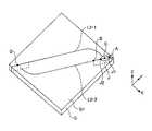
図1は、本発明による脆性材料基板の割断装置10の一実施形態を示す概略図である。図1(A)は、割断装置10により実現される割断方法の第1工程を示し、図1(B)は割断装置10により実現される割断方法の第2工程を示す。図1において、Aは脆性材料基板Gの表面G1におけるレーザ光の照射位置を示し、Bは脆性材料基板G(以下、「基板G」ともいう)の表面G1(以下、「基板表面G1」ともいう)における割断の先端位置を示す。また、本実施形態におけるレーザ光は集光された光束である。よって照射位置Aは、一点に集光させた場合の焦点以外では面積を持つ一定の範囲を表す。 FIG. 1 is a schematic view showing an embodiment of a brittle material
図1に示すように、割断装置10は、脆性材料基板Gを支持するステージ20と、脆性材料基板Gを加工する加工ヘッド30と、ステージ20と加工ヘッド30とを相対的に移動させる第1の駆動機構40と、制御手段50とを備える。 As shown in FIG. 1, the cleaving
割断装置10は、割断線L1に沿って基板Gを割断するため、先ず、図1(A)に示すように、基板表面G1にスクライブ線L2を割断線L1に沿って形成する。次いで、図1(B)に示すように、基板表面G1におけるレーザ光の照射位置Aをスクライブ線L2に沿って移動させて基板Gを割断する。 In order to cleave the substrate G along the cutting line L1, the cleaving
割断装置10の割断対象となる脆性材料基板Gは、レーザ光を吸収する性質を有する板状部材であり、例えば、ソーダライムガラスや無アルカリガラス等のガラス板、金属シリコン等の金属板、アルミナ等のセラミックス板である。基板Gの厚さは、通常のガラス板であれば、1〜6mmであることが望ましい。厚さが1mm未満であると、車両用窓ガラスとして十分な強度が得られない。また、6mm以上であると重量が重くなり車両用窓ガラスに適さない。特に1.5〜4.0mmであれば強度と重量のバランスから車両用窓ガラスに好適である。 The brittle material substrate G to be cleaved by the cleaving
ステージ20は、脆性材料基板Gの裏面G2(以下、「基板裏面G2」ともいう)を支持する支持面22を備える。ステージ20は、基板裏面G2の全面を支持してもよいし、基板裏面G2の一部を支持していてもよい。基板Gは、支持面22に吸着固定されてもよいし、支持面22に粘着固定されてもよい。 The
加工ヘッド30は、ステージ20の上方に待機しており、ステージ20(即ち、基板G)に対してX方向、Y方向、Z方向に移動可能に取り付けられている。この加工ヘッド30には、スクライブカッター32、発振器34及び光学系36が組み込まれている。 The
前述のように加工ヘッド30にスクライブカッター32、発振器34及び光学系36を一体化して搭載することにより、装置10が簡素化、小型化できコスト的にも有利になる。一方で、スクライブカッター32、発振器34及び光学系36をそれぞれ分離して搭載することも可能である。複数の加工ヘッドに分離して各装置を搭載した場合、各装置の移動パターンの自由度が高まる。また、同一軌跡を通る制御が容易になり、加熱―冷却のタイムラグを小さくできるとともに、スクライブ線L2とレーザ照射位置Aの意図的なずらし(オフセット)制御が容易になる。その結果、割断条件設定の自由度と生産性の高い割断装置を実現できる。 As described above, by integrally mounting the
スクライブカッター32は、脆性材料基板Gにスクライブ線L2を形成するものである。スクライブ線L2は、スクライブカッター32の先端を基板表面G1に押し付けて移動することにより形成される。尚、第1の実施形態のスクライブ線L2はスクライブカッター32を用いて形成されるが、レーザ光を用いてスクライブ線L2を形成してもよく、スクライブ線L2を形成する手段に制限はない。 The
スクライブカッター32の先端は、例えば、ダイヤモンドや超鋼合金で形成される。スクライブカッター32は、基板表面G1を誤って傷つけないように、加工ヘッド30の外筒の内部に収容され、必要に応じて加工ヘッド30の外筒の外に突き出されてもよい。 The tip of the
割断装置10は、レーザ光を照射して、スクライブ線L2上の点を起点として亀裂を伸展させて基板Gを割断する。 The cleaving
発振器34は、レーザ光を発振するものである。発振器34には、基板Gとしてソーダライムガラス板を割断する場合、795〜1030nmの波長のレーザ光を発振する高出力で高効率な半導体レーザが好適に用いられる。例えば、InGaAsP系半導体レーザ(波長:808nm又は940nm)は、Alフリーで長寿命であり好適に用いることができる。 The
795〜1030nmの波長のレーザ光は、一部がガラス板Gを透過し、他の一部がガラス板Gに熱として吸収され、残部がガラス板Gによって反射される。即ち、795〜1030nmの波長のレーザ光は、レーザ光の透過率及び吸収率が十分であるので、熱応力分布を最適化することができる。前述よりレーザ光の波長が長いと半導体レーザの例えば100W以上の高出力レーザ発振器の作製が困難になり、さらに長い波長においては(例えば波長10600nm(CO2レーザ))でソーダライムガラス板Gの表面G1での吸収が増加し、ガラス表面から厚さ方向(Z方向)で5μm以内では、ほぼ100%表面吸収されてしまう。その結果、ガラス板の内部をレーザ光により直接加熱することができなくなる。レーザ光の大部分がソーダライムガラス板Gの表面G1近傍で熱として吸収されると、ガラスは一般に熱伝導率が低いので、基板表面G1、即ち、スクライブ線L2が過熱されることになる。これにより、スクライブ線L2形成時に導入された微細なチッピング(潜在亀裂)を起点として亀裂が面内方向(X方向、Y方向)にも伸展する。その結果、割断時のガラス屑の量が多くなったり、割断面の品質が低下したりする。A part of the laser light having a wavelength of 795 to 1030 nm is transmitted through the glass plate G, the other part is absorbed by the glass plate G as heat, and the rest is reflected by the glass plate G. That is, the laser light having a wavelength of 795 to 1030 nm has a sufficient transmittance and absorption rate of the laser light, so that the thermal stress distribution can be optimized. When the wavelength of the laser beam is long as described above, it becomes difficult to manufacture a high-power laser oscillator of, for example, 100 W or more of the semiconductor laser, and at a longer wavelength (for example, a wavelength of 10600 nm (CO2 laser)), the surface of the soda lime glass plate G Absorption at G1 increases, and surface absorption is almost 100% within 5 μm in the thickness direction (Z direction) from the glass surface. As a result, the inside of the glass plate cannot be directly heated by the laser beam. When most of the laser light is absorbed as heat in the vicinity of the surface G1 of the soda lime glass plate G, since the glass generally has low thermal conductivity, the substrate surface G1, that is, the scribe line L2 is overheated. Thereby, the crack extends in the in-plane direction (X direction, Y direction) starting from the fine chipping (latent crack) introduced when the scribe line L2 is formed. As a result, the amount of glass waste at the time of cleaving increases, or the quality of the cleaved surface decreases.
一方、レーザ光の波長が短いと、レーザ光の透過率が高くなるので、割断に十分な応力を得ることが困難になる。 On the other hand, if the wavelength of the laser beam is short, the transmittance of the laser beam becomes high, so that it is difficult to obtain sufficient stress for cleaving.
また、レーザ光の出力は、単位体積×時間当たりの照射エネルギー量とガラスの厚さや物性によって適宜設定可能である。ソーダライムガラスを割断する場合、割断対象物の照射部分の温度は、歪点以下の温度である必要があるため、好ましくは500℃以下、さらには50〜300℃が好適である。レーザ光の出力が低いと割断に十分な応力を得ることが困難になる。 Further, the output of the laser beam can be appropriately set according to the irradiation energy amount per unit volume × time and the thickness and physical properties of the glass. When soda lime glass is cleaved, the temperature of the irradiated portion of the cleaved object needs to be equal to or lower than the strain point, and is preferably 500 ° C. or lower, and more preferably 50 to 300 ° C. If the output of the laser beam is low, it will be difficult to obtain sufficient stress for cleaving.
発振器34から発振されたレーザ光は、集光レンズ等の光学系36によって基板Gに向けて集光され、基板表面G1に照射される。 The laser light oscillated from the
図2は、レーザ光が基板表面G1に照射される様子の一例を示す図であり、(A)は斜視図、(B)は照射位置Aの移動方向と直交する断面図である。図3は、レーザ光が基板表面G1に照射される様子の別の例を示す図であり、(A)は斜視図、(B)は照射位置Aの移動方向と直交する断面図である。図2及び図3において、Fはレーザ光の集光位置を示す。 2A and 2B are diagrams illustrating an example of a state in which the laser beam is irradiated onto the substrate surface G1, in which FIG. 2A is a perspective view, and FIG. 2B is a cross-sectional view orthogonal to the moving direction of the irradiation position A. 3A and 3B are diagrams showing another example of the state in which the laser beam is irradiated onto the substrate surface G1, in which FIG. 3A is a perspective view, and FIG. 3B is a cross-sectional view orthogonal to the moving direction of the irradiation position A. 2 and 3, F indicates a condensing position of the laser beam.
図2に示す例では、レーザ光は、断面円形状であり同心円状に集光され、図3に示す例では、レーザ光は、断面矩形状に集光される。矩形断面のレーザ光は、照射位置Aの移動方向と直交する方向の寸法Wが集光位置Fに向けて変化し、照射位置Aの移動方向と平行な方向の寸法Vがレーザ光の光軸に略並行に照射される。 In the example shown in FIG. 2, the laser light has a circular cross section and is collected concentrically. In the example shown in FIG. 3, the laser light is collected in a rectangular cross section. In the laser beam having a rectangular cross section, the dimension W in the direction orthogonal to the moving direction of the irradiation position A changes toward the condensing position F, and the dimension V in the direction parallel to the moving direction of the irradiation position A is the optical axis of the laser light. Is irradiated substantially in parallel.
レーザ光の集光角α(図2、図3参照)は、照射位置Aの移動方向と直交する断面において、10〜34°が好ましい。 The condensing angle α (see FIGS. 2 and 3) of the laser light is preferably 10 to 34 ° in a cross section orthogonal to the moving direction of the irradiation position A.
このとき、レーザ光の集光位置Fは、割断対象物の熱伝導率、強度などによって適宜設定可能であり、例えば図2及び図3に示すように基板表面G1を基準として基板裏面G2と同じ側にあってもよいし、基板表面G1を基準として基板裏面G2と反対側にあってもよい。 At this time, the condensing position F of the laser beam can be appropriately set depending on the thermal conductivity, strength, etc. of the object to be cut, and is the same as the substrate back surface G2 with reference to the substrate surface G1 as shown in FIGS. 2 and 3, for example. It may be on the side, or may be on the side opposite to the substrate back surface G2 with respect to the substrate surface G1.
集光角αが34°を超えると、レーザ光の断面形状が光軸に沿って大きく変化するので、基板表面G1と基板裏面G2とにおける熱応力差が拡大して割断面の品質が低下する。また、レーザ光の断面形状が光軸に沿って大きく変化するので、集光位置Fの誤差が不均一な熱応力分布を発生やすくなり、割断面の品質が不安定になる。 When the condensing angle α exceeds 34 °, the cross-sectional shape of the laser light greatly changes along the optical axis, so that the thermal stress difference between the substrate surface G1 and the substrate back surface G2 is enlarged, and the quality of the cut surface is degraded. . In addition, since the cross-sectional shape of the laser light greatly changes along the optical axis, it becomes easy to generate a thermal stress distribution in which the error of the condensing position F is not uniform, and the quality of the fractured surface becomes unstable.
一方、集光角αが10°未満になると、基板表面G1と基板裏面G2とにおける熱応力差が制御し難くなり、割断面の品質が低下する。 On the other hand, when the condensing angle α is less than 10 °, it becomes difficult to control the thermal stress difference between the substrate front surface G1 and the substrate back surface G2, and the quality of the fractured surface deteriorates.
また、レーザ光は、基板表面G1において、照射位置Aの移動方向と直交する方向の寸法W(図2、図3参照)が2〜10mmであることが好ましく、3〜7mmがより好ましい。 The laser light preferably has a dimension W (see FIGS. 2 and 3) in the direction orthogonal to the moving direction of the irradiation position A on the substrate surface G1, and more preferably 3 to 7 mm.
基板表面G1における寸法Wが2mm未満になると、スクライブ線L2が加熱されるので、亀裂がスクライブ線L2と直交する面内方向(X方向、Y方向)にも伸展し、割断面精度が低下する。また、照射位置Aの誤差が不均一な熱応力分布を発生やすくなり、割断面の品質が不安定になる。 When the dimension W on the substrate surface G1 is less than 2 mm, the scribe line L2 is heated, so that the crack extends in the in-plane direction (X direction, Y direction) perpendicular to the scribe line L2, and the accuracy of the fractured section decreases. . Moreover, it becomes easy to generate | occur | produce the thermal stress distribution with which the error of the irradiation position A is non-uniform | heterogenous, and the quality of a fractured surface becomes unstable.
一方、基板表面G1における寸法Wが10mmを超えると、不要な部分が加熱され温度差をつけにくくなるため、スクライブ線L2において発生する引張応力が小さくなる。その結果、割断に十分な熱応力を得ることが困難になり、割断面の品質が不安定になる。 On the other hand, when the dimension W on the substrate surface G1 exceeds 10 mm, an unnecessary portion is heated and it becomes difficult to make a temperature difference, so that the tensile stress generated in the scribe line L2 is reduced. As a result, it becomes difficult to obtain sufficient thermal stress for cleaving, and the quality of the fractured surface becomes unstable.
加工ヘッド30は、第1の駆動機構40によってステージ20に対してX方向、Y方向及びZ方向に相対的に移動される。上記機能を実現するためには、基板Gを支持するステージ20を固定しておき加工ヘッド30を第1の駆動機構40により移動させてもよい。第1の駆動機構40は、周知の構成であってよく、例えば、加工ヘッド30をX方向、Y方向及びZ方向に案内するXYZガイドレールと、加工ヘッド30を駆動するアクチュエータとを含み構成される。また、加工ヘッド30を固定しておき基板Gを支持するステージ20を移動させてもよく、20及び30の双方を同時に移動する制御を行うことも可能である。 The
このようにして、第1の実施形態では、基板表面G1にスクライブ線L2を形成し、基板表面G1におけるレーザ光の照射位置Aをスクライブ線L2に沿って移動させる。発振器34の出力制御や、第1の駆動機構40の出力制御は、マイクロコンピュータからなる制御手段50により実現される。 Thus, in the first embodiment, the scribe line L2 is formed on the substrate surface G1, and the irradiation position A of the laser beam on the substrate surface G1 is moved along the scribe line L2. The output control of the
制御手段50には、加工ヘッド30の位置座標を計測する位置センサ(図示せず)等が接続されている。制御手段50は、位置センサ等からの制御信号に基づいて、以下で説明する割断装置10の各種動作を制御する。なお、上述した図2及び図3では、レーザ光は断面円形状又は断面矩形状であるとしたが、断面楕円形状であってもよい。また、レーザ光の種類は割断する脆性材料基板の物性によって適宜変更することができ、ガラス以外の割断対象であれば、例えば、CO2レーザ(波長:10600nm)、YAGレーザ(波長:1064nm)、半導体レーザ等を用いることもできる。A position sensor (not shown) for measuring the position coordinates of the
次に、第1の実施形態の脆性材料基板の割断方法について、図1を参照にして説明する。 Next, a method for cleaving the brittle material substrate according to the first embodiment will be described with reference to FIG.
先ず、基板Gがステージ20上に載置され、加工ヘッド30が基板Gの割断線L1の始端(始点)に対向する位置まで移動されると、加工ヘッド30が下降し始める。その後、加工ヘッド30のスクライブカッター32が下降し、基板表面G1に所定条件で押し当てられ、図1(A)に示すように、スクライブ線L2が所定速度で引かれる。 First, when the substrate G is placed on the
スクライブ線L2の形成が終了すると、次いで、加工ヘッド30が上昇し、加工ヘッド30がスクライブ線L2の始端に対向する位置まで再移動すると、加工ヘッド30が下降する。加工ヘッド30が基板表面G1に対して所定距離まで近づくと、レーザ光が発振器34から発振される。発振器34から発振されたレーザ光は、光学系36によって集光され、スクライブ線L2の始端に照射される。 When the formation of the scribe line L2 is completed, the
次に、図1の(B)に示すように、基板表面G1におけるレーザ光の照射位置Aをスクライブ線L2に沿って移動させると、基板Gが照射位置Aより移動方向前方で割断される。 Next, as shown in FIG. 1B, when the irradiation position A of the laser beam on the substrate surface G1 is moved along the scribe line L2, the substrate G is cleaved ahead of the irradiation position A in the movement direction.
このとき、割断の先端位置Bはレーザ光の照射位置Aより移動方向前方にある。図2(A)及び図3(A)に示すように、レーザ光の照射領域では、レーザ光の一部が熱として吸収されるので、照射領域の周囲と比較して高温になり、基板Gの熱膨張により圧縮応力(矢印P)が発生する。一方、照射領域の周囲では、反作用により引張応力(矢印Q)が発生する。この引張応力により、スクライブ線L2上の点を起点として亀裂を伸展させて割断を開始する。尚、スクライブ線L2上の点を起点として亀裂を伸展させて割断するので、割断面の基板表面G1側はスクライブ線L2に略一致する。 At this time, the cleaved tip position B is ahead of the laser beam irradiation position A in the moving direction. As shown in FIGS. 2A and 3A, in the laser light irradiation region, a part of the laser light is absorbed as heat, so that the temperature becomes higher than that around the irradiation region, and the substrate G Compressive stress (arrow P) is generated due to thermal expansion. On the other hand, tensile stress (arrow Q) is generated by the reaction around the irradiated region. By this tensile stress, the crack is extended starting from a point on the scribe line L2, and cleaving is started. In addition, since the crack is extended and cleaved from a point on the scribe line L2, the substrate surface G1 side of the cut surface substantially coincides with the scribe line L2.
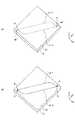
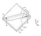
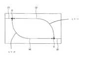
図4の(A)及び(B)に2本の割断線により所望の形状の脆性材料基板Gをトリミングするときの割断線及びスクライブ線の一例を示す。(A)は割断線L1−1,L1−2を示す斜視図、(B)はスクライブ線L2−1,L2−2を示す斜視図である。図4に示す例では、第1及び第2の割断線L1−1、L1−2は、独立した割断線であり、且つ、第1の割断線L1−1の先端で第2の割断線L1−2と交差する第1の交点Cと、第2の割断線L1−2の先端で第1の割断線L1−1と交差する第2の交点Dとを有する。 FIGS. 4A and 4B show an example of a breaking line and a scribe line when trimming a brittle material substrate G having a desired shape by two breaking lines. (A) is a perspective view which shows the cutting lines L1-1 and L1-2, (B) is a perspective view which shows the scribe lines L2-1 and L2-2. In the example shown in FIG. 4, the first and second breaking lines L1-1 and L1-2 are independent breaking lines, and the second breaking line L1 at the tip of the first breaking line L1-1. -2 and a second intersection D that intersects the first breaking line L1-1 at the tip of the second breaking line L1-2.
また、図4に示す例では、第1のスクライブ線L2−1は第1の交点C近傍を除いて第1の割断線L1−1に沿って形成し、第2のスクライブ線L2−2は第2の交点D近傍を除いて第2の割断線L1−2に沿って形成する。即ち、第1のスクライブL2−1は先端で第2のスクライブ線L2−2から離れており、第2のスクライブ線L2−2は先端で第1のスクライブ線L2−1から離れている。言い換えると、第1及び第2のスクライブ線L2−1、L2−2は、互いに独立し離間している。 In the example shown in FIG. 4, the first scribe line L2-1 is formed along the first breaking line L1-1 except for the vicinity of the first intersection C, and the second scribe line L2-2 is It is formed along the second breaking line L1-2 except for the vicinity of the second intersection D. That is, the first scribe L2-1 is separated from the second scribe line L2-2 at the tip, and the second scribe line L2-2 is separated from the first scribe line L2-1 at the tip. In other words, the first and second scribe lines L2-1 and L2-2 are separated from each other independently.
仮に、第1及び第2のスクライブ線L2−1、L2−2を交差して形成すると、第1及び第2の交点C、Dにおいて基板表面G1に欠けやチッピングが発生するので、割断面の品質が低下する。一方、第1の実施形態では、第1及び第2のスクライブ線L2−1、L2−2を離間して形成するので、割断面の品質の向上が可能になる。 If the first and second scribe lines L2-1 and L2-2 are formed so as to intersect, chipping or chipping occurs at the substrate surface G1 at the first and second intersections C and D. Quality deteriorates. On the other hand, in the first embodiment, since the first and second scribe lines L2-1 and L2-2 are formed apart from each other, the quality of the cut surface can be improved.
第1及び第2のスクライブ線L2−1、L2−2の離間距離Eは、0.3〜3mmが好ましく、0.3〜1mmがより好ましい。離間距離Eが0.3mm未満になると、スクライブカッター32の位置を厳密に制御する必要があり、一方、離間距離Eが3mmを超えると、亀裂の起点として離れすぎてしまい、亀裂を割断線L1に沿って伸展させることが困難になる。 The distance E between the first and second scribe lines L2-1 and L2-2 is preferably 0.3 to 3 mm, and more preferably 0.3 to 1 mm. When the separation distance E is less than 0.3 mm, it is necessary to strictly control the position of the
ところで、上述の如く、第1の交点C近傍において照射位置Aを第2の割断線L1−2に沿って移動させると、熱応力により第1のスクライブ線L2−1上の点を起点として亀裂が伸展する。この熱応力は第1のスクライブ線L2−1に対して左右非対称に発生するので、割断面の品質に悪影響を及ぼす。また、第2の交点D近傍において照射位置Aを第1の割断線L1−1に沿って移動させると、熱応力により第2のスクライブ線L2−2上の点を起点として亀裂が伸展する。この熱応力は第2のスクライブ線L2−2に対して左右非対称に発生するので、割断面の品質に悪影響を及ぼす。 By the way, as described above, when the irradiation position A is moved in the vicinity of the first intersection C along the second breaking line L1-2, cracks start from a point on the first scribe line L2-1 due to thermal stress. Extends. Since this thermal stress occurs asymmetrically with respect to the first scribe line L2-1, it adversely affects the quality of the split section. Further, when the irradiation position A is moved along the first breaking line L1-1 in the vicinity of the second intersection point D, the crack extends from the point on the second scribe line L2-2 due to thermal stress. Since this thermal stress occurs asymmetrically with respect to the second scribe line L2-2, it adversely affects the quality of the split section.
この影響は、スクライブ線のない領域で特に顕著になる。第1及び第2の交点C、D近傍において第1のスクライブ線L2−1と第2のスクライブ線L2−2とを離間して形成するため亀裂の起点となる点がなく、割断面を形成する亀裂が割断線から外れたり、蛇行したりするためである。 This effect is particularly noticeable in regions where there are no scribe lines. Since the first scribe line L2-1 and the second scribe line L2-2 are formed apart from each other in the vicinity of the first and second intersections C and D, there is no point as a starting point of a crack, and a split section is formed. This is because the crack to be removed from the breaking line or to meander.
そこで、本実施形態では以下のごとく、前述の割断面の品質が向上した割断方法を実現した。図5〜図8は、図4に示す基板Gの割断工程の一例を時系列的に示す図である。図9は図5の要部を拡大した図である。図に示す第1の実施形態では、第1の割断線L1−1と第2の割断線L1−2とが交差する第1及び第2の交点C、D近傍の第1及び第2の領域J及びK(図5、図6参照)の内側において、レーザ光の照射を制限する。この制限は、前述の領域J、Kの内側における最高温度と最低温度との温度差ΔTj、ΔTkを小さくすることができればよく、レーザ光の出力自体を制限してもよいし、照射位置Aの移動速度を高速にしてもよく、上記機能の実現方法に制限はない。尚、第1の実施形態では、上記機能を実現するため、レーザ光の出力を中断し、レーザ光の照射を中断する。 Therefore, in the present embodiment, the cleaving method in which the quality of the above-described fractured surface is improved is realized as follows. 5-8 is a figure which shows an example of the cutting process of the board | substrate G shown in FIG. 4 in time series. FIG. 9 is an enlarged view of the main part of FIG. In the first embodiment shown in the figure, first and second regions in the vicinity of the first and second intersections C and D where the first breaking line L1-1 and the second breaking line L1-2 intersect. Laser irradiation is limited inside J and K (see FIGS. 5 and 6). This limitation is not limited as long as the temperature differences ΔTj and ΔTk between the maximum temperature and the minimum temperature inside the regions J and K described above can be reduced, and the output of the laser beam itself may be limited. The moving speed may be increased, and the method for realizing the above function is not limited. In the first embodiment, in order to realize the above function, the output of the laser beam is interrupted and the irradiation of the laser beam is interrupted.
図6に示した第1の領域Jは、第2の割断線L1−2の一部を含む一定範囲であって、例えば第1の交点Cを中心とする一定範囲であってもよいし、或いは第1のスクライブ線L2−1の先端と近接する近接点(図示せず)を中心とする一定範囲であってもよい。同様に図5に示した第2の領域Kは、第1の割断線L1−1の一部を含む一定範囲であって、例えば第2の交点Dを中心とする一定範囲であってもよいし、或いは第2のスクライブ線L2−2の先端と近接する近接点(図示せず)を中心とする一定範囲であってもよい。 The first region J shown in FIG. 6 is a fixed range including a part of the second breaking line L1-2, and may be a fixed range centered on the first intersection C, for example. Alternatively, it may be a certain range centered on a proximity point (not shown) close to the tip of the first scribe line L2-1. Similarly, the second region K shown in FIG. 5 is a fixed range including a part of the first breaking line L1-1, and may be a fixed range centered on the second intersection D, for example. Alternatively, it may be a certain range centered on a proximity point (not shown) close to the tip of the second scribe line L2-2.
第1及び第2の領域J、Kの割断線に沿った長さは、5〜50mmが好ましく、10〜30mmがより好ましい。5mm未満になると、レーザ光の照射を制限する領域が狭すぎるため、割断面の品質が低下する。一方、50mmを超えると、照射位置Aが第1及び第2の領域J、Kの一端J1、K1に達したとき熱応力により基板Gが第1及び第2の領域J、Kの他端J2、K2まで割断されることが難しくなる。 5-50 mm is preferable and, as for the length along the breaking line of 1st and 2nd area | regions J and K, 10-30 mm is more preferable. If the thickness is less than 5 mm, the area that restricts the irradiation of the laser beam is too narrow, and the quality of the fractured surface deteriorates. On the other hand, when it exceeds 50 mm, when the irradiation position A reaches one end J1, K1 of the first and second regions J, K, the substrate G is exposed to the other end J2 of the first, second regions J, K by thermal stress. , It becomes difficult to cleave up to K2.
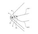
本実施形態の割断工程においては、先ず、図4に示した第1の割断線L1−1上の基板Gの外縁に照射位置Aを位置合わせする。このとき、図5及び図9に示したように照射位置Aの移動方向前端は、第2の領域Kの一端K1を含むように位置決めされている。この状態で、レーザ光を所定時間(例えば、0.5s)照射し、基板Gを第1のスクライブ線L2−1に沿って基板Gの外縁から少なくとも第2の領域Kの移動方向前方の他端K2まで割断する。即ち、割断の先端位置Bが第1の割断線L1−1に沿って第2の交点Dを超えて第1の交点Cの途中まで達する。その後、レーザ光の照射を中断する。 In the cleaving process of the present embodiment, first, the irradiation position A is aligned with the outer edge of the substrate G on the first cleaving line L1-1 shown in FIG. At this time, as shown in FIGS. 5 and 9, the moving direction front end of the irradiation position A is positioned so as to include one end K <b> 1 of the second region K. In this state, the laser beam is irradiated for a predetermined time (for example, 0.5 s), and the substrate G is moved along the first scribe line L2-1 from the outer edge of the substrate G at least in the moving direction of the second region K. Cut to end K2. That is, the leading end position B of the cleaving reaches the middle of the first intersecting point C beyond the second intersecting point D along the first breaking line L1-1. Thereafter, the laser beam irradiation is interrupted.
次いで、第1の割断線L1−2上の基板Gの外縁に照射位置Aを位置合わせする。このとき、図6に示したように照射位置Aの移動方向前端は、第1の領域Jの一端J1を含むように位置決めされている。この状態で、レーザ光を所定時間(例えば、0.5s)照射し、熱応力により基板Gを第2の割断線L1−2に沿って基板Gの外縁から少なくとも第1の領域Jの移動方向前方の他端J2まで割断する。即ち、割断の先端位置Bが第1のスクライブ線L2−2に沿って第1の交点Cを超えて第2の交点Dの途中まで達する。その後、レーザ光の照射を中断する。 Next, the irradiation position A is aligned with the outer edge of the substrate G on the first breaking line L1-2. At this time, the moving direction front end of the irradiation position A is positioned so as to include one end J1 of the first region J as shown in FIG. In this state, the laser beam is irradiated for a predetermined time (for example, 0.5 s), and the substrate G is moved along the second breaking line L1-2 by the thermal stress from the outer edge of the substrate G at least in the moving direction of the first region J. Cut to the other front end J2. In other words, the cleaving tip position B reaches the middle of the second intersection D beyond the first intersection C along the first scribe line L2-2. Thereafter, the laser beam irradiation is interrupted.
次いで、照射位置Aの移動方向後端を、図7に示すように、図5の工程で割断された第2の領域Kの他端K2を含むように位置決めする。その後、レーザ光の照射を再開し、照射位置Aを第1のスクライブ線L2−1に沿って第1の交点Cに向けて移動させて、基板Gを第1のスクライブ線L2−1に沿って残りの第1の交点Cまで割断する。その後、レーザ光の照射を中断する。 Next, as shown in FIG. 7, the rear end of the irradiation position A in the moving direction is positioned so as to include the other end K2 of the second region K cleaved in the step of FIG. Thereafter, the laser beam irradiation is resumed, the irradiation position A is moved along the first scribe line L2-1 toward the first intersection C, and the substrate G is moved along the first scribe line L2-1. To the remaining first intersection C. Thereafter, the laser beam irradiation is interrupted.
ここで、第1の交点C近傍において、図4に示した基板Gを第1の割断線L1−1に沿って割断するために、第1の領域Jの内側における最高温度と最低温度との温度差ΔTjを15℃以下とすることが好ましく、10℃以下とすることがより好ましい。仮に、温度差ΔTjが15℃を超える状態で割断すると、図6に示す工程の影響により第1の領域Jの内側における温度分布が第1の割断線L1−1に対して左右で不均一になっているので、割断面の品質に悪影響を及ぼす。一方、第1の実施形態では、温度差ΔTjを15℃以下とするので、温度差ΔTjの影響を抑制することができ、割断面の品質が向上する。 Here, in the vicinity of the first intersection C, in order to cleave the substrate G shown in FIG. 4 along the first breaking line L1-1, the maximum temperature and the minimum temperature inside the first region J The temperature difference ΔTj is preferably 15 ° C. or less, more preferably 10 ° C. or less. If the temperature difference ΔTj is cleaved with the temperature difference exceeding 15 ° C., the temperature distribution inside the first region J is not uniform left and right with respect to the first cleave line L1-1 due to the influence of the process shown in FIG. As a result, the quality of the section is adversely affected. On the other hand, in the first embodiment, since the temperature difference ΔTj is set to 15 ° C. or less, the influence of the temperature difference ΔTj can be suppressed, and the quality of the cut surface is improved.
最後に、図8に示すように、照射位置Aの移動方向後端を、図6の工程で割断された第1の領域Jの他端J2を含むように位置決めする。その後、レーザ光の照射を再開し、照射位置Aを第2の割断線L1−2に沿って第2の交点Dに向けて移動させて、基板Gを第2の割断線L1−2に沿って残りの第2の交点Dまで割断して割断工程を終了する。 Finally, as shown in FIG. 8, the rear end in the movement direction of the irradiation position A is positioned so as to include the other end J2 of the first region J cleaved in the process of FIG. Thereafter, the irradiation of the laser beam is resumed, the irradiation position A is moved along the second breaking line L1-2 toward the second intersection D, and the substrate G is moved along the second breaking line L1-2. Then, the remaining cutting point D is divided and the cleaving process is completed.
ここで、第2の交点D近傍において、図4に示した基板Gを第2の割断線L1−2に沿って割断するために、第2の領域Kの内側における最高温度と最低温度との温度差ΔTkを15℃以下とすることが好ましく、10℃以下とすることがより好ましい。これにより図8を用いて前述したと同様に割断面の品質を向上することができる。また、第2の交点D近傍におけるレーザ照射についても前述の第1の交点C近傍で得られた効果と同様の効果を奏する。 Here, in the vicinity of the second intersection D, in order to cleave the substrate G shown in FIG. 4 along the second cleaving line L1-2, the maximum temperature and the minimum temperature inside the second region K are The temperature difference ΔTk is preferably 15 ° C. or less, more preferably 10 ° C. or less. As a result, the quality of the fractured surface can be improved as described above with reference to FIG. Also, laser irradiation in the vicinity of the second intersection D has the same effect as that obtained in the vicinity of the first intersection C described above.
以上の照射順を模式的に表したのが図10であり、図10の矢印(1)〜(4)の順に照射を行う際に第2の交点Dの近傍における温度差ΔTkを制御することにより、本発明の目的が達成される。 FIG. 10 schematically shows the above irradiation order, and the temperature difference ΔTk in the vicinity of the second intersection D is controlled when irradiation is performed in the order of arrows (1) to (4) in FIG. Thus, the object of the present invention is achieved.
図10に示したレーザ光の照射順で割断する場合は、第2の交点D近傍の基板Gを第2の割断線L1−2に沿って割断する際に、レーザ光の照射を制限しても良いし、制限しなくても良い。いずれの場合であっても、基板Gを照射位置Aの移動方向前方で割断するので、照射位置Aが第2の交点D近傍に達する前に割断が終了するからである。 When cleaving in the order of laser light irradiation shown in FIG. 10, the laser light irradiation is limited when cleaving the substrate G in the vicinity of the second intersection D along the second breaking line L1-2. It does not have to be restricted. In any case, since the substrate G is cleaved in front of the irradiation position A in the moving direction, the cleaving is completed before the irradiation position A reaches the vicinity of the second intersection D.
以上のように第1の実施形態では、先の工程で割断線の交点近傍の領域において基板Gの外縁から少なくとも第2の領域Kの移動方向前方の他端K2まで割断するので、他端K2にレーザ光を照射したとき、他端K2から一端K1に向けて亀裂が伸展せず、良好な割断面が得られる。 As described above, in the first embodiment, in the previous step, in the region near the intersection of the breaking line, the cutting is performed from the outer edge of the substrate G to at least the other end K2 in the moving direction of the second region K. When the laser beam is irradiated to the laser beam, the crack does not extend from the other end K2 toward the one end K1, and a good fracture surface is obtained.
割断の先端位置Bが、移動方向前方の他端K2の手前までしか達していない場合、後工程で他端K2にレーザ光を照射すると(図7参照)、他端K2から一端K1に向けて亀裂が伸展する。このような場合、第2の領域Kにおける割断面が段状になり、割断線の精度や割断面の垂直性などの割断面の品質が低下する。 When the cleaving tip position B has reached only before the other end K2 in front of the movement direction, when the other end K2 is irradiated with laser light in the subsequent process (see FIG. 7), the other end K2 toward the one end K1. The crack extends. In such a case, the fractured surface in the second region K is stepped, and the quality of the fractured surface such as the accuracy of the fracture line and the perpendicularity of the fractured surface is degraded.
一方、図11に図10の変形例を示した。図11に示した順にレーザ光の照射を行う場合は、事前に交点C近傍において割断の先端位置Bを、割断線L1−2上の移動方向前方の他端J2まで伸展させている。このため、他端J2にレーザ光を照射したとき、他端J2から一端J1に向けて亀裂が伸展せず、割断面の品質が向上する。割断の先端位置Bが、移動方向前方の他端J2の手前までしか達していない場合は、後工程で他端J2にレーザ光を照射すると(図8参照)、前述のように、照射位置Aの進行方向と逆向きに亀裂が伸展し割断面の品質が低下する。 On the other hand, FIG. 11 shows a modification of FIG. When laser light irradiation is performed in the order shown in FIG. 11, the cleaving tip position B is extended in advance in the vicinity of the intersection C to the other end J2 in the moving direction on the cleaving line L1-2. For this reason, when the other end J2 is irradiated with the laser beam, the crack does not extend from the other end J2 toward the one end J1, and the quality of the cut section is improved. When the cleaving tip position B reaches only before the other end J2 in front of the moving direction, when the other end J2 is irradiated with a laser beam in a subsequent process (see FIG. 8), as described above, the irradiation position A Cracks extend in the direction opposite to the direction of travel, and the quality of the cut section deteriorates.
尚、図11に示すレーザ光の照射順で割断する場合は、第1の交点C近傍の基板Gを第1の割断線L1−1に沿って割断する際に、レーザ光の照射を制限しても良いし、制限しなくても良い。第1の交点C近傍の第1の割断線L1−1に沿った割断を行う際の基板Gの温度条件は、非対称性による悪影響が少ないからである。 In addition, when cleaving in the irradiation order of the laser light shown in FIG. 11, when the substrate G in the vicinity of the first intersection C is cleaved along the first breaking line L1-1, the irradiation of the laser light is limited. It does not have to be restricted. This is because the temperature condition of the substrate G when performing cutting along the first cutting line L1-1 in the vicinity of the first intersection C is less affected by asymmetry.
また、図9では照射位置Aを第1の割断線L1−1上の基板Gの外縁に位置合わせする例を示したが、照射開始の位置合わせは、レーザの照射位置Aにスクライブ線の端部K1が含まれ、かつ、レーザ照射後に領域Kの移動方向前方の他端K2まで割断可能な点であればよく、照射位置Aの中心点は基板Gの外縁に限定されない。また、これは図6で示した領域Jの近傍についても同様である。 FIG. 9 shows an example in which the irradiation position A is aligned with the outer edge of the substrate G on the first breaking line L1-1. The alignment at the start of irradiation is performed at the end of the scribe line at the laser irradiation position A. The center point of the irradiation position A is not limited to the outer edge of the substrate G as long as it includes the portion K1 and can be cleaved to the other end K2 in the moving direction of the region K after laser irradiation. This also applies to the vicinity of the region J shown in FIG.
以上のように、第1の実施形態によれば、基板表面G1におけるレーザ光の照射位置Aをスクライブ線L2に沿って相対的に移動させて脆性材料基板Gを照射位置Aより移動方向前方で割断する。このとき、レーザ光の照射によりスクライブ線上の点を起点にレーザ加熱とほぼ同時に割断が進行するため、レーザ加熱後に割断を進展させるために用いられる冷却装置が不要となる。これにより、装置10を複雑化することなく脆性材料基板Gを割断することができる。 As described above, according to the first embodiment, the irradiation position A of the laser beam on the substrate surface G1 is relatively moved along the scribe line L2, and the brittle material substrate G is moved in front of the irradiation position A in the movement direction. Cleave. At this time, since the cleaving progresses almost simultaneously with the laser heating starting from the point on the scribe line by the irradiation of the laser light, a cooling device used to advance the cleaving after the laser heating becomes unnecessary. Thereby, the brittle material substrate G can be cleaved without complicating the
また、第1の実施形態によれば、第1及び第2の割断線L1−1、L1−2が交差する第1及び第2の交点C、D近傍の第1及び第2の領域J、Kの内側において、レーザ光の照射を制限する。その結果、意図しない亀裂の伸展を防止することができ、割断面の品質が向上する。これは、第1及び第2のスクライブ線L2−1、L2−2を離間して形成する場合に、特に顕著になる。 Further, according to the first embodiment, the first and second regions J in the vicinity of the first and second intersections C and D where the first and second breaking lines L1-1 and L1-2 intersect, The laser beam irradiation is limited inside K. As a result, unintended crack extension can be prevented, and the quality of the fractured surface is improved. This is particularly noticeable when the first and second scribe lines L2-1 and L2-2 are formed apart from each other.
更に、第1の実施形態によれば、照射位置Aが第2の領域Kの一端K1に達したとき、基板Gが第1の割断線L1−1に沿って少なくとも第2の領域Kの他端K2まで割断される。また、照射位置Aが第1の領域Jの一端J1に達したとき、基板Gが第2の割断線L1−2に沿って少なくとも第1の領域Jの他端J2まで割断される。これにより、他端J2、K2にレーザ光を照射しても、他端J2、K2から一端J1、K1に向けて亀裂が伸展せず、割断面が段状になることを防止することができ、割断面の品質が向上する。 Furthermore, according to the first embodiment, when the irradiation position A reaches one end K1 of the second region K, the substrate G is at least other than the second region K along the first breaking line L1-1. It is cleaved to the end K2. When the irradiation position A reaches one end J1 of the first region J, the substrate G is cut along at least the other end J2 of the first region J along the second cutting line L1-2. As a result, even when the other ends J2 and K2 are irradiated with laser light, cracks do not extend from the other ends J2 and K2 toward the one ends J1 and K1, and it is possible to prevent the split section from becoming stepped. , The quality of the cut surface is improved.
更にまた、第1の実施形態によれば、第1の交点C近傍において、基板Gを第2の割断線L1−2に沿って割断した後、第1の割断線L1−1に沿って割断する際に、第1の領域Jの内側における最高温度と最低温度との温度差ΔTjを15℃以下とする。また、第2の交点D近傍において、基板Gを第1の割断線L1−1に沿って割断した後、第2の割断線L1−2に沿って割断する際に、第2の領域Kの内側における最高温度と最低温度との温度差ΔTkを15℃以下とする。これにより、温度の影響を抑制することができ、割断面の品質が向上する。 Furthermore, according to the first embodiment, the substrate G is cleaved along the second breaking line L1-2 in the vicinity of the first intersection C, and then cleaved along the first breaking line L1-1. In this case, the temperature difference ΔTj between the maximum temperature and the minimum temperature inside the first region J is set to 15 ° C. or less. Further, in the vicinity of the second intersection point D, after the substrate G is cleaved along the first breaking line L1-1 and then cleaved along the second breaking line L1-2, The temperature difference ΔTk between the maximum temperature and the minimum temperature on the inner side is set to 15 ° C. or less. Thereby, the influence of temperature can be suppressed and the quality of a fractured surface improves.
図12及び図13は、スクライブ線の別の例を示す斜視図である。図4では独立した2本のスクライブ線によって基板Gを割断する例を示したが、スクライブ線は必ずしも独立している必要はなく、図12のように連続した一のスクライブ線の一部でスクライブ線L2−1、L2−2を形成し、割断線の交点Dを形成してもよい。また、図13は、3本以上のスクライブ線によってインカーブ形状を含む所望の形状の基板Gをトリミングする例である。図13に示すようにインカーブ形状を切り出すために、複数本のスクライブ線L2−1〜L2−6により3点以上の割断線の交点を形成して基板Gを割断することも可能である。 12 and 13 are perspective views showing other examples of the scribe lines. FIG. 4 shows an example in which the substrate G is cleaved by two independent scribe lines. However, the scribe lines do not necessarily have to be independent, and the scribe lines are part of one continuous scribe line as shown in FIG. Lines L2-1 and L2-2 may be formed, and the intersection D of the breaking lines may be formed. FIG. 13 is an example in which a substrate G having a desired shape including an in-curve shape is trimmed by three or more scribe lines. In order to cut out the in-curve shape as shown in FIG. 13, it is also possible to cleave the substrate G by forming intersections of three or more breaking lines with a plurality of scribe lines L2-1 to L2-6.
また、本実施形態のレーザ割断を用いると、従来の曲げ応力による割断方法と異なり板内部の応力で割れる。このため割断された基板Gの対向する割断面が接近、接触する方向に移動しないで割断することができ、割断面同士がこすれることがない。その結果、割断時の切断屑(カレット)の発生量を低減することができるとともに、不要な欠けなどの割断面の品質低下を防止することができる。以上の結果、製品の歩留まりを向上させるのみではなく、カレットが減少することにより、切断屑汚れによる品質不良の低減、洗浄工程の簡素化、製造装置の摩耗低減による寿命の延長などの効果も期待できる。 Further, when the laser cleaving according to the present embodiment is used, it is divided by the stress inside the plate unlike the conventional cleaving method by bending stress. For this reason, it is possible to cleave the cleaved substrate G without moving in the direction in which the opposing cut surfaces approach and contact each other, and the cleaved surfaces are not rubbed. As a result, it is possible to reduce the amount of cutting waste (cullet) generated at the time of cleaving, and to prevent the quality of the cut section from being deteriorated such as unnecessary chips. As a result of the above, not only the product yield is improved, but also the reduction of cullet is expected to reduce the quality defects due to dirt from cutting waste, simplify the cleaning process, and extend the service life by reducing the wear of manufacturing equipment. it can.
次に、本発明の第2の実施形態について説明する。図14は、本発明による脆性材料基板の割断装置の第2の実施形態を示す概略図である。割断装置100は、図1に示す割断装置10と比較して、熱処理手段60と、ステージ20と熱処理手段60とを相対的に移動させる第2の駆動機構70とを更に備える。その他の構成は、図1と同様であるので、詳しい説明は省略する。 Next, a second embodiment of the present invention will be described. FIG. 14 is a schematic view showing a second embodiment of the cleaving apparatus for a brittle material substrate according to the present invention. The cleaving
熱処理手段60は、脆性材料基板Gの少なくとも一部を能動的に加熱又は冷却する。熱処理手段60は、周知の構成であってよく、例えば、空気を吹き付ける空冷ノズル機構を備えてもよく、冷媒を貯蔵する冷媒タンクと冷媒を基板表面G1に向けて吹き付ける冷媒スプレーノズルとを含み構成されてもよい。また、制御手段50に加熱冷却条件を制御できる機構を設けることがさらに好ましい。 The heat treatment means 60 actively heats or cools at least a part of the brittle material substrate G. The heat treatment means 60 may have a known configuration, for example, may include an air cooling nozzle mechanism that blows air, and includes a refrigerant tank that stores refrigerant and a refrigerant spray nozzle that blows the refrigerant toward the substrate surface G1. May be. Further, it is more preferable to provide the control means 50 with a mechanism that can control the heating and cooling conditions.
この熱処理手段60は、ステージ20の上方に待機しており、第2の駆動機構70によってステージ20に対してX方向、Y方向、Z方向に移動される。上記機能を実現するためには、基板Gを支持するステージ20を固定しておき熱処理手段60を第2の駆動機構70により移動させてもよいし、熱処理手段60を固定しておき基板Gを支持するステージ20を第2の駆動機構70により移動させてもよい。第2の駆動機構70は、周知の構成であってよく、熱処理手段60をX方向、Y方向及びZ方向に案内するXYZガイドレールと、熱処理手段60を駆動するアクチュエータとを含み構成される。 The heat treatment means 60 stands by above the
このようにして、第2の実施形態では、脆性材料基板Gの所定領域は、選択的に加熱又は冷却される。このときの熱処理手段60の出力制御や、第2の駆動機構70の出力制御は、マイクロコンピュータからなる制御手段50により実現される。制御手段50には、熱処理手段60の位置座標を計測する位置センサ(図示せず)等が接続されている。制御手段50は、位置センサ等からの出力信号に基づいて、以下で説明する割断装置100の動作を制御する。 In this way, in the second embodiment, the predetermined region of the brittle material substrate G is selectively heated or cooled. The output control of the heat treatment means 60 and the output control of the
次に、第2の実施形態の脆性材料基板の割断方法について、図15を参照して説明する。図15は、図7及び図8で示した工程の間に行われる工程を示す図である。その他の工程は、図5〜図8と同様であるので、詳しい説明は省略する。 Next, a cleaving method for a brittle material substrate according to the second embodiment will be described with reference to FIG. FIG. 15 is a diagram illustrating a process performed between the processes illustrated in FIGS. 7 and 8. The other steps are the same as those shown in FIGS.
図15に示すように、第2の交点D近傍において、第1のスクライブ線L2−1に沿って割断した(図5参照)後であって、第2のスクライブ線L2−2に沿って割断する(図8参照)前に、第2の交点D近傍を熱処理手段60で加熱又は冷却する。これにより、第2の交点D近傍の第2の領域Kの内側における温度分布を均一にすることができ、割断面の品質が向上する。 As shown in FIG. 15, in the vicinity of the second intersection D, after cleaving along the first scribe line L2-1 (see FIG. 5), cleaving along the second scribe line L2-2. Before (see FIG. 8), the vicinity of the second intersection D is heated or cooled by the heat treatment means 60. Thereby, the temperature distribution inside the second region K in the vicinity of the second intersection D can be made uniform, and the quality of the fractured surface is improved.
仮に、第2の交点D近傍を加熱又は冷却しない場合、第2の領域Kの内側における温度差ΔTkが15℃以下になるまで待機する必要がある。一方、第2の実施形態では、第2の交点D近傍を熱処理手段60により能動的に加熱又は冷却するので、図5及び図7に示す工程の影響を積極的に抑制することができる。 If the vicinity of the second intersection D is not heated or cooled, it is necessary to wait until the temperature difference ΔTk inside the second region K becomes 15 ° C. or less. On the other hand, in the second embodiment, since the vicinity of the second intersection D is actively heated or cooled by the heat treatment means 60, the influence of the steps shown in FIGS. 5 and 7 can be positively suppressed.
尚、加熱又は冷却する領域Mは、第2の領域Kの内側における温度分布を均一にするため、第2の領域Kを含む広範囲に亘ることが好ましい。 The region M to be heated or cooled preferably covers a wide range including the second region K in order to make the temperature distribution inside the second region K uniform.
以上のように、第2の実施形態によれば、第2の交点D近傍において、第2の交点D近傍を加熱又は冷却することにより、図5及び図7に示す工程の影響を積極的に抑制することができ、割断面の品質が向上する。 As described above, according to the second embodiment, in the vicinity of the second intersection D, by heating or cooling the vicinity of the second intersection D, the influence of the steps shown in FIGS. It can suppress, and the quality of a fractured surface improves.
なお、レーザ照射及び熱処理の順序は前述に限定されず、第2の交点D近傍において、例えば図6に示す工程後であって図7に示す工程前に第2の交点D近傍を加熱又は冷却してもよく、この場合、図5に示す工程の影響を積極的に抑制することができる。加えて、第1の交点C近傍において、第2の割断線L1−2に沿って割断した(図6参照)後であって第1の割断線L1−1に沿って割断する(図7参照)前に、第1の交点C近傍を加熱又は冷却してもよい。 Note that the order of laser irradiation and heat treatment is not limited to the above, and the vicinity of the second intersection D is heated or cooled in the vicinity of the second intersection D, for example, after the step shown in FIG. 6 and before the step shown in FIG. In this case, the influence of the process shown in FIG. 5 can be positively suppressed. In addition, in the vicinity of the first intersection C, after cleaving along the second breaking line L1-2 (see FIG. 6), cleaving along the first breaking line L1-1 (see FIG. 7). Before) the vicinity of the first intersection C may be heated or cooled.
以下、実施例により本発明を更に詳細に説明する。
(例1〜4)
フロート法によって製造された幅305mm、長さ305mm、厚さ3.5mmの緑系ソーダライムガラス板 (旭硝子社製:自動車用ガラス板)を用意し、このガラス板Gを図1に示すステージ20上に載置した。次に、ダイヤモンドカッター32をガラス基板表面G1に60Nの力で押し当て、図4に示すスクライブ線L2−1,L2−2を速度200mm/sで引いた。Hereinafter, the present invention will be described in more detail with reference to examples.
(Examples 1-4)
A green soda-lime glass plate (manufactured by Asahi Glass Co., Ltd .: automotive glass plate) having a width of 305 mm, a length of 305 mm, and a thickness of 3.5 mm prepared by the float process is prepared, and this glass plate G is a
各例1〜4において、離間距離Eは0.5mmとした。
次いで、図3に示すレーザ光をガラス板Gの表面G1に照射し、図5〜図8に示したように、照射位置Aをスクライブ線L2−1,L2−2に沿って速度100mm/sで移動させガラス板Gを割断した。In each of Examples 1 to 4, the separation distance E was 0.5 mm.
Next, the laser beam shown in FIG. 3 is irradiated on the surface G1 of the glass plate G, and as shown in FIGS. 5 to 8, the irradiation position A is set at a speed of 100 mm / s along the scribe lines L2-1 and L2-2. The glass plate G was cleaved.
各例1〜4において、レーザ光の照射条件は、波長:808nm、集光角α:32°、集光位置F:基板表面G1を基準として基板裏面G2とは反対側、出力:600W、基板表面G1における照射形状(寸法W×寸法V):5×10mmとした。また、第1の領域Jは、第2の割断線L1−2上の第1の交点Cを中心とする前後20mm(全長40mm)の範囲とした。また、第2の領域Kは、第1の割断線L1−1上の第2の交点Dを中心とする前後20mm(全長40mm)の範囲とした。 In each of Examples 1 to 4, the laser light irradiation conditions are as follows: wavelength: 808 nm, condensing angle α: 32 °, condensing position F: substrate surface G1 on the opposite side from the substrate back surface G2, output: 600 W, substrate Irradiation shape on surface G1 (dimension W × dimension V): 5 × 10 mm. Moreover, the 1st area | region J was made into the range of 20 mm back and front (40 mm in total length) centering on the 1st intersection C on the 2nd breaking line L1-2. In addition, the second region K was set to a range of 20 mm before and after (
また、各例1〜4において、図7及び図8に示す工程において第2の交点D近傍にレーザ光をそれぞれ照射する間での待機時間T(放冷時間)で変えて経時的な温度差ΔTkを測定した。温度差ΔTkの測定には、赤外線サーモグラフィを用いた。各例1〜4における、温度差ΔTkを表1示す。なお、ここで待機時間Tは、レーザ光を照射する際の装置とガラス板の相対移動に必要な最低限の制御時間を含まず、加工ヘッド30の駆動を一時停止して加工ヘッド30を積極的に待機させた時間を指すものとする。 Further, in each of Examples 1 to 4, the temperature difference over time is changed by the waiting time T (cooling time) during which the laser beam is irradiated in the vicinity of the second intersection D in the steps shown in FIGS. ΔTk was measured. Infrared thermography was used to measure the temperature difference ΔTk. Table 1 shows the temperature difference ΔTk in each of Examples 1 to 4. Here, the waiting time T does not include the minimum control time required for relative movement between the apparatus and the glass plate when irradiating the laser beam, and the driving of the
(例5)
例5では、レーザ光の照射を制限することなく、照射位置Aを第1の割断線L1−1に沿って始点から終点まで(即ち、第2の交点Dを超えて第1の交点Cまで)移動させ、次いで、照射位置Aを第2の割断線L1−2に沿って始点から終点まで(即ち、第1の交点Cを超えて第2の交点Dまで)移動させた。これ以外の条件は、例1〜4と同様にして、ガラス板Gを割断した。(Example 5)
In Example 5, the irradiation position A is changed from the start point to the end point along the first breaking line L1-1 (that is, beyond the second intersection point D to the first intersection point C) without limiting the laser beam irradiation. Then, the irradiation position A was moved from the start point to the end point along the second breaking line L1-2 (ie, beyond the first intersection C to the second intersection D). Other conditions were the same as in Examples 1 to 4, and the glass plate G was cleaved.

例1〜4の割断面の基板裏面G2側の位置ずれを測定した結果を図16に示す。図16において、横軸は割断面の基板表面G1側の第2の交点Dからの距離(単位:mm)であり、縦軸は割断面の基板表面G1側と基板裏面G2側との平面視での位置のずれ(単位:mm)であって割断面の基板表面G1に対する垂直性を表す。この第2の交点Dからの距離は、第2の割断線L1−2に沿って測定し、第1の交点Cに向かう方向を正とした。また、位置のずれは、基板裏面G2側が基板表面G1側に比較して第2のスクライブ線L2−2と直交する矢印N方向(図8参照)を負とした。 The result of having measured the position shift by the side of the board | substrate back surface G2 of the split surface of Examples 1-4 is shown in FIG. In FIG. 16, the horizontal axis is the distance (unit: mm) from the second intersection D on the substrate surface G1 side of the split section, and the vertical axis is a plan view of the substrate surface G1 side and substrate back surface G2 side of the split section. This is a positional deviation (unit: mm) and represents the perpendicularity to the substrate surface G1 of the split section. The distance from the second intersection D was measured along the second breaking line L1-2, and the direction toward the first intersection C was positive. Further, the positional deviation was negative in the direction of arrow N (see FIG. 8) perpendicular to the second scribe line L2-2 on the substrate back surface G2 side as compared with the substrate surface G1 side.
図16によれば例1〜2では、基板表面G1側の割断線に対しても位置ずれが小さく、基板裏面G2側の割断位置の位置ずれも減少して割断面が直角に近い形状で割断されていることが分かる。その結果、割断後の割断面品質により優れるガラス板が得られた。 According to FIG. 16, in Examples 1 and 2, the positional deviation is small with respect to the breaking line on the substrate surface G1 side, the positional deviation on the cleavage position on the substrate back surface G2 side is also reduced, and the fractured surface is cleaved in a shape close to right angle. You can see that. As a result, a glass plate that was superior in the quality of the fractured surface after cleaving was obtained.
割断面を観察した結果、例5では、第1及び第2の領域J、Kの内側において600Wの出力のレーザ光を照射したので、意図しない方向に亀裂が進展し割断面の基板表面G1側と割断線との位置ズレにより割断面の精度が低下し、所望の形状のガラス板が得られなかった。 As a result of observing the fractured surface, in Example 5, the laser beam of 600 W output was irradiated inside the first and second regions J and K, so that cracks developed in an unintended direction and the substrate surface G1 side of the fractured surface Due to the misalignment between the cleaved line and the cleaved line, the accuracy of the cut section was lowered, and a glass plate with a desired shape could not be obtained.
以上、本発明の好ましい実施例について詳説したが、本発明は、上述した実施例に制限されることはなく、本発明の範囲を逸脱することなく、上述した実施例に種々の変形及び置換を加えることができる。 The preferred embodiments of the present invention have been described in detail above. However, the present invention is not limited to the above-described embodiments, and various modifications and substitutions can be made to the above-described embodiments without departing from the scope of the present invention. Can be added.
本発明は、自動車に代表される車両用窓ガラス、その他の車両、航空機、船舶又は建築物等の窓ガラス、薄型ディスプレイパネル用ガラス基板、ハードディスク用基板、その他セラミックスの加工や製造に適用できる。
なお、2009年7月3日に出願された日本特許出願2009−159016号の明細書、特許請求の範囲、図面及び要約書の全内容をここに引用し、本発明の明細書の開示として、取り入れるものである。
The present invention can be applied to processing and manufacturing of window glass for vehicles represented by automobiles, window glass for other vehicles, aircraft, ships, buildings, etc., glass substrates for thin display panels, hard disk substrates, and other ceramics.
The entire contents of the specification, claims, drawings, and abstract of Japanese Patent Application No. 2009-159016 filed on July 3, 2009 are cited herein as disclosure of the specification of the present invention. Incorporated.
10 脆性材料基板の割断装置
20 ステージ
30 加工ヘッド
32 スクライブカッター
34 発振器
36 光学系(集光レンズ)
40 第1の駆動機構
50 制御手段
60 熱処理手段
70 第2の駆動機構DESCRIPTION OF
40
Claims (12)
Translated fromJapanese前記脆性材料基板の表面にスクライブ線を前記第1及び第2の割断線に沿って形成する第1工程と、
前記脆性材料基板の表面におけるレーザ光の照射位置を前記スクライブ線に沿って相対的に移動させて前記脆性材料基板を前記照射位置より移動方向前方で割断する第2工程とを有し、
前記第1及び第2の割断線が交差する交点近傍の領域の内側において、前記レーザ光の照射を制限することを特徴とする脆性材料基板の割断方法。A method of cleaving a brittle material substrate by condensing and irradiating a laser beam to the brittle material substrate along first and second cutting lines intersecting at least at one point,
Forming a scribe line on the surface of the brittle material substrate along the first and second breaking lines;
A second step of relatively moving the irradiation position of the laser beam on the surface of the brittle material substrate along the scribe line to cleave the brittle material substrate in the moving direction from the irradiation position;
A method for cleaving a brittle material substrate, wherein irradiation of the laser beam is restricted inside a region near an intersection where the first and second cleaving lines intersect.
前記第1の割断線は、前記第1の割断線の先端で前記第2の割断線と交差する第1の交点と、少なくとも1つの他の交点とを有し、
前記第2工程は、
前記第1の割断線に沿って前記他の交点を超えて前記第1の交点の途中まで割断する工程と、
前記第1の割断線に沿って残りの前記第1の交点まで割断する工程とを有する請求項1に記載の脆性材料基板の割断方法。The brittle material substrate has at least the first and second breaking lines independent of each other;
The first breaking line has a first intersection that intersects the second breaking line at a tip of the first breaking line, and at least one other intersection.
The second step includes
Cleaving to the middle of the first intersection beyond the other intersection along the first breaking line;
The method for cleaving the brittle material substrate according to claim 1, further comprising: cleaving to the remaining first intersection along the first cleaving line.
前記第2工程は、
前記第1の割断線に沿って前記第2の交点を超えて前記第1の交点の途中まで割断する工程と、
前記第2の割断線に沿って前記第1の交点を超えて前記第2の交点の途中まで割断する工程と、
前記第1の割断線に沿って残りの前記第1の交点まで割断する工程と、
前記第2の割断線に沿って残りの前記第2の交点まで割断する工程とを有する請求項1に記載の脆性材料基板の割断方法。The first and second breaking lines are independent breaking lines, and a first intersection that intersects the second breaking line at a tip of the first breaking line and a tip of the second breaking line And a second intersection that intersects the first breaking line,
The second step includes
Cleaving to the middle of the first intersection beyond the second intersection along the first breaking line;
Cleaving to the middle of the second intersection beyond the first intersection along the second breaking line;
Cleaving to the remaining first intersection along the first cleaving line;
The method of cleaving the brittle material substrate according to claim 1, further comprising a step of cleaving to the remaining second intersection along the second cleaving line.
第2のスクライブ線を前記第2の交点近傍を除いて前記第2の割断線に沿って形成する請求項8に記載の脆性材料基板の割断方法。Forming a first scribe line along the first breaking line except in the vicinity of the first intersection;
The method for cleaving a brittle material substrate according to claim 8, wherein a second scribe line is formed along the second cleaving line except in the vicinity of the second intersection.
少なくとも1点で交差する第1及び第2の割断線に沿って脆性材料基板を割断するため、あらかじめ前記第1及び第2の割断線に沿ってスクライブ線が形成された前記脆性材料基板の表面におけるレーザ光の照射位置を前記スクライブ線に沿って相対的に移動させて、前記脆性材料基板を前記照射位置より移動方向前方で割断する脆性材料基板の割断装置であって、
前記脆性材料基板を支持するステージと、
前記レーザ光を発振する発振器と、
前記発振器から発振された前記レーザ光を前記脆性材料基板に向けて集光する光学系と、
前記ステージと前記発振器及び前記光学系とを相対的に移動させる第1の駆動機構と、
前記発振器の出力及び前記第1の駆動機構の出力を制御する制御手段とを備え、
前記制御手段は、第1及び第2の割断線が交差する交点近傍の領域の内側において、前記レーザ光の照射を制限することを特徴とする脆性材料基板の割断装置。A cleaving device for cleaving the brittle material substrate by irradiating the brittle material substrate with laser light,
A surface of the brittle material substrate on which a scribe line is formed in advance along the first and second breaking lines in order to break the brittle material substrate along the first and second breaking lines that intersect at least at one point. The apparatus for cleaving a brittle material substrate that relatively moves the irradiation position of the laser beam along the scribe line and cleaves the brittle material substrate in the moving direction from the irradiation position,
A stage for supporting the brittle material substrate;
An oscillator for oscillating the laser beam;
An optical system that focuses the laser light oscillated from the oscillator toward the brittle material substrate;
A first drive mechanism for relatively moving the stage, the oscillator, and the optical system;
Control means for controlling the output of the oscillator and the output of the first drive mechanism,
The brittle material substrate cleaving apparatus, wherein the control means limits the irradiation of the laser beam inside a region near an intersection where the first and second cleaving lines intersect.
前記ステージと前記熱処理手段とを相対的に移動させる第2の駆動機構とを更に備え、
前記制御手段は、前記熱処理手段の出力及び前記第2の駆動機構の出力を制御して、前記交点近傍において、前記脆性材料基板を前記第1の割断線に沿って割断した後であって前記第2の割断線に沿って割断する前に、前記交点近傍を加熱又は冷却する請求項11に記載の脆性材料基板の割断装置。Heat treatment means for heating or cooling at least a part of the brittle material substrate;
A second drive mechanism for relatively moving the stage and the heat treatment means;
The control means controls the output of the heat treatment means and the output of the second drive mechanism, and after cutting the brittle material substrate along the first breaking line in the vicinity of the intersection, The brittle material substrate cleaving apparatus according to claim 11, wherein the vicinity of the intersection is heated or cooled before cleaving along the second cleaving line.
Priority Applications (1)
| Application Number | Priority Date | Filing Date | Title |
|---|---|---|---|
| JP2011520999AJP5609870B2 (en) | 2009-07-03 | 2010-07-02 | Cleaving method and cleaving apparatus for brittle material substrate, and vehicle window glass obtained by the cleaving method |
Applications Claiming Priority (4)
| Application Number | Priority Date | Filing Date | Title |
|---|---|---|---|
| JP2009159016 | 2009-07-03 | ||
| JP2009159016 | 2009-07-03 | ||
| JP2011520999AJP5609870B2 (en) | 2009-07-03 | 2010-07-02 | Cleaving method and cleaving apparatus for brittle material substrate, and vehicle window glass obtained by the cleaving method |
| PCT/JP2010/061351WO2011002089A1 (en) | 2009-07-03 | 2010-07-02 | Cutting method and cutting device for brittle material substrate, and vehicle window glass obtained by the cutting method |
Publications (2)
| Publication Number | Publication Date |
|---|---|
| JPWO2011002089A1 JPWO2011002089A1 (en) | 2012-12-13 |
| JP5609870B2true JP5609870B2 (en) | 2014-10-22 |
Family
ID=43411157
Family Applications (1)
| Application Number | Title | Priority Date | Filing Date |
|---|---|---|---|
| JP2011520999AActiveJP5609870B2 (en) | 2009-07-03 | 2010-07-02 | Cleaving method and cleaving apparatus for brittle material substrate, and vehicle window glass obtained by the cleaving method |
Country Status (5)
| Country | Link |
|---|---|
| US (1) | US20120135847A1 (en) |
| EP (1) | EP2450169A4 (en) |
| JP (1) | JP5609870B2 (en) |
| CN (1) | CN102470549A (en) |
| WO (1) | WO2011002089A1 (en) |
Families Citing this family (27)
| Publication number | Priority date | Publication date | Assignee | Title |
|---|---|---|---|---|
| US8932510B2 (en) | 2009-08-28 | 2015-01-13 | Corning Incorporated | Methods for laser cutting glass substrates |
| US8946590B2 (en) | 2009-11-30 | 2015-02-03 | Corning Incorporated | Methods for laser scribing and separating glass substrates |
| TWI513670B (en)* | 2010-08-31 | 2015-12-21 | Corning Inc | Methods of separating strengthened glass substrates |
| KR101800223B1 (en)* | 2011-06-08 | 2017-11-22 | 니폰 덴키 가라스 가부시키가이샤 | Method for cutting plate-like glass, and cutting device therefor |
| US20130140291A1 (en)* | 2011-12-05 | 2013-06-06 | Shenzhen China Star Optoelectronics Technology Co., Ltd. | Glass Substrate Slicing Apparatus and Method |
| JP2013147380A (en)* | 2012-01-19 | 2013-08-01 | Hamamatsu Photonics Kk | Method for laser beam machining |
| US8716625B2 (en)* | 2012-02-03 | 2014-05-06 | Trumpf Werkzeugmaschinen Gmbh + Co. Kg | Workpiece cutting |
| US9938180B2 (en) | 2012-06-05 | 2018-04-10 | Corning Incorporated | Methods of cutting glass using a laser |
| JP5991860B2 (en)* | 2012-06-19 | 2016-09-14 | 三星ダイヤモンド工業株式会社 | Glass substrate processing method |
| DE112013003503B4 (en)* | 2012-07-10 | 2020-02-13 | AGC Inc. | Process for processing a glass plate |
| KR101355807B1 (en)* | 2012-09-11 | 2014-02-03 | 로체 시스템즈(주) | Curve cutting method for non-metallic materials |
| US9610653B2 (en) | 2012-09-21 | 2017-04-04 | Electro Scientific Industries, Inc. | Method and apparatus for separation of workpieces and articles produced thereby |
| WO2014208700A1 (en)* | 2013-06-27 | 2014-12-31 | 日本電気硝子株式会社 | Method for scribing tempered glass sheet |
| US9260337B2 (en)* | 2014-01-09 | 2016-02-16 | Corning Incorporated | Methods and apparatus for free-shape cutting of flexible thin glass |
| CN107922259B (en) | 2015-09-04 | 2021-05-07 | Agc株式会社 | Method for producing glass plate, method for producing glass article, and apparatus for producing glass article |
| JP2019023146A (en)* | 2015-12-08 | 2019-02-14 | Agc株式会社 | Glass plate and method of producing glass plate |
| JP6996508B2 (en) | 2016-09-01 | 2022-01-17 | Agc株式会社 | Manufacturing method of glass articles and glass articles |
| JP6531878B2 (en)* | 2017-02-21 | 2019-06-19 | Agc株式会社 | Glass plate and method of manufacturing glass plate |
| CN110291051B (en)* | 2017-02-21 | 2022-04-29 | Agc株式会社 | Glass plate and method for manufacturing glass plate |
| CN110788486B (en)* | 2019-11-07 | 2022-04-15 | 武汉华工激光工程有限责任公司 | Systematic precision machining method for brittle transparent material special-shaped 3D structure |
| JP7421162B2 (en)* | 2020-01-08 | 2024-01-24 | 日本電気硝子株式会社 | Glass plate manufacturing method |
| KR20210093051A (en)* | 2020-01-17 | 2021-07-27 | 코닝 인코포레이티드 | Method of manufacturing a glass laminate article |
| CN111732333A (en)* | 2020-06-16 | 2020-10-02 | 湖南艾凯瑞斯智能科技有限公司 | Glass optical filter cutting method |
| WO2022216674A1 (en)* | 2021-04-08 | 2022-10-13 | Bromden Ventures Llc | Glass windows with matched edges and joined edges |
| CN113927181B (en)* | 2021-11-15 | 2024-06-18 | 苏州科韵激光科技有限公司 | Laser cutting device and laser cutting method |
| JP2023074021A (en)* | 2021-11-17 | 2023-05-29 | Jswアクティナシステム株式会社 | Laser cutting device, laser cutting method, and display manufacturing method |
| CN115740867A (en)* | 2022-12-01 | 2023-03-07 | 渤海造船厂集团有限公司 | Welding seam centering and scribing device and method |
Citations (9)
| Publication number | Priority date | Publication date | Assignee | Title |
|---|---|---|---|---|
| JPS48102816A (en)* | 1972-04-10 | 1973-12-24 | ||
| JPH0632628A (en)* | 1991-09-12 | 1994-02-08 | Bando Kiko Kk | Method for processing glass sheet and apparatus therefor |
| JP2001176820A (en)* | 1999-12-15 | 2001-06-29 | Hitachi Cable Ltd | Substrate processing method and processing apparatus |
| JP2002178179A (en)* | 2000-12-12 | 2002-06-25 | Sony Corp | Cracking device and method for the same |
| JP2004217492A (en)* | 2003-01-17 | 2004-08-05 | Murakami Corp | Method of cutting out glass plate |
| WO2004067243A1 (en)* | 2003-01-29 | 2004-08-12 | Mitsuboshi Diamond Industrial Co., Ltd. | Substrate dividing apparatus and method for dividing substrate |
| JP2006261447A (en)* | 2005-03-17 | 2006-09-28 | Toshiba Corp | Semiconductor device and method for manufacturing semiconductor device |
| JP2007048995A (en)* | 2005-08-11 | 2007-02-22 | Toshiba Corp | Manufacturing method of semiconductor device |
| JP2007217213A (en)* | 2006-02-15 | 2007-08-30 | Shibaura Mechatronics Corp | Cleaving device and cleaving method |
Family Cites Families (42)
| Publication number | Priority date | Publication date | Assignee | Title |
|---|---|---|---|---|
| DE1244346B (en)* | 1964-10-19 | 1967-07-13 | Menzel Gerhard Glasbearbeitung | Method of cutting glass |
| US3751238A (en)* | 1970-02-25 | 1973-08-07 | Corning Glass Works | Method of chemically strengthening a silicate article containing soda |
| DE3041342A1 (en) | 1980-11-03 | 1982-06-09 | Fichtel & Sachs Ag, 8720 Schweinfurt | MULTI-DISC CLUTCH WITH FORCED LIFT AND SIMPLIFIED ASSEMBLY |
| DE3110235A1 (en)* | 1981-03-17 | 1982-10-21 | Trumpf GmbH & Co, 7257 Ditzingen | "METHOD AND DEVICE FOR FLAME-CUTTING BY MEANS OF A LASER BEAM" |
| US4467168A (en)* | 1981-04-01 | 1984-08-21 | Creative Glassworks International | Method of cutting glass with a laser and an article made therewith |
| DE69013047T2 (en)* | 1989-05-08 | 1995-04-13 | Philips Nv | Process for splitting a plate made of brittle material. |
| RU2024441C1 (en)* | 1992-04-02 | 1994-12-15 | Владимир Степанович Кондратенко | Process of cutting of nonmetal materials |
| JP2524477B2 (en)* | 1993-12-20 | 1996-08-14 | インターナショナル・ビジネス・マシーンズ・コーポレイション | Liquid crystal panel forming substrate and manufacturing method thereof |
| KR100447786B1 (en)* | 1995-08-31 | 2004-11-06 | 코닝 인코포레이티드 | Method and apparatus for brittle material cutting |
| MY120533A (en)* | 1997-04-14 | 2005-11-30 | Schott Ag | Method and apparatus for cutting through a flat workpiece made of brittle material, especially glass. |
| US6407360B1 (en)* | 1998-08-26 | 2002-06-18 | Samsung Electronics, Co., Ltd. | Laser cutting apparatus and method |
| US6211488B1 (en)* | 1998-12-01 | 2001-04-03 | Accudyne Display And Semiconductor Systems, Inc. | Method and apparatus for separating non-metallic substrates utilizing a laser initiated scribe |
| US6252197B1 (en)* | 1998-12-01 | 2001-06-26 | Accudyne Display And Semiconductor Systems, Inc. | Method and apparatus for separating non-metallic substrates utilizing a supplemental mechanical force applicator |
| US6420678B1 (en)* | 1998-12-01 | 2002-07-16 | Brian L. Hoekstra | Method for separating non-metallic substrates |
| KR100626983B1 (en)* | 1999-06-18 | 2006-09-22 | 미쓰보시 다이야몬도 고교 가부시키가이샤 | Scribing method by use of laser |
| DE19952331C1 (en)* | 1999-10-29 | 2001-08-30 | Schott Spezialglas Gmbh | Method and device for quickly cutting a workpiece from brittle material using laser beams |
| DE19963939B4 (en)* | 1999-12-31 | 2004-11-04 | Schott Spezialglas Gmbh | Method and device for cutting flat workpieces made of brittle material |
| DE10016628A1 (en)* | 2000-04-04 | 2001-10-18 | Schott Glas | Process for the production of small thin glass panes and larger thin glass panes as a semi-finished product for this manufacture |
| DE10041519C1 (en)* | 2000-08-24 | 2001-11-22 | Schott Spezialglas Gmbh | Method and device for cutting a flat glass plate into several rectangular plates |
| JP4659300B2 (en)* | 2000-09-13 | 2011-03-30 | 浜松ホトニクス株式会社 | Laser processing method and semiconductor chip manufacturing method |
| TW592868B (en)* | 2001-07-18 | 2004-06-21 | Mitsuboshi Diamond Ind Co Ltd | Device and method for scribing fragile material substrate |
| CN100335259C (en)* | 2002-03-12 | 2007-09-05 | 三星钻石工业股份有限公司 | Scribing method and device for processing brittle materials |
| US6787732B1 (en)* | 2002-04-02 | 2004-09-07 | Seagate Technology Llc | Method for laser-scribing brittle substrates and apparatus therefor |
| KR100657196B1 (en)* | 2002-11-06 | 2006-12-14 | 미쓰보시 다이야몬도 고교 가부시키가이샤 | Scribe line forming device and scribe line forming method |
| US7723641B2 (en)* | 2003-01-10 | 2010-05-25 | Mitsuboshi Diamond Industrial Co., Ltd. | Brittle material substrate scribing device and scribing method, and automatic analysis line |
| WO2004083133A2 (en)* | 2003-03-21 | 2004-09-30 | Rorze Systems Corporation | Apparatus for cutting glass plate |
| JP2005268752A (en)* | 2004-02-19 | 2005-09-29 | Canon Inc | Laser cleaving method, member to be cleaved, and semiconductor element chip |
| US7723212B2 (en)* | 2004-07-30 | 2010-05-25 | Mitsuboshi Diamond Industrial Co., Ltd | Method for forming median crack in substrate and apparatus for forming median crack in substrate |
| JP3887394B2 (en)* | 2004-10-08 | 2007-02-28 | 芝浦メカトロニクス株式会社 | Brittle material cleaving system and method |
| WO2006043690A1 (en)* | 2004-10-20 | 2006-04-27 | Semiconductor Energy Laboratory Co., Ltd. | Laser irradiation method, laser irradiation apparatus and method for manufacturing semiconductor device |
| DE102005024497B4 (en)* | 2005-05-27 | 2008-06-19 | Schott Ag | Method for mechanically breaking scored flat workpieces from brittle material |
| US7626138B2 (en)* | 2005-09-08 | 2009-12-01 | Imra America, Inc. | Transparent material processing with an ultrashort pulse laser |
| KR101081613B1 (en)* | 2005-09-13 | 2011-11-09 | 가부시키가이샤 레미 | Method for scribing fragile material and apparatus for scribing fragile material |
| DE102006033217A1 (en)* | 2006-07-14 | 2008-01-17 | Jenoptik Automatisierungstechnik Gmbh | Method for producing optically perceptible laser-induced cracks in brittle material |
| US8011207B2 (en)* | 2007-11-20 | 2011-09-06 | Corning Incorporated | Laser scoring of glass sheets at high speeds and with low residual stress |
| JP2009159016A (en) | 2007-12-25 | 2009-07-16 | Canon Inc | Image reading device |
| CN101497493B (en)* | 2008-02-01 | 2012-12-26 | 鸿富锦精密工业(深圳)有限公司 | Laser cutting device |
| US8232218B2 (en)* | 2008-02-29 | 2012-07-31 | Corning Incorporated | Ion exchanged, fast cooled glasses |
| US8051679B2 (en)* | 2008-09-29 | 2011-11-08 | Corning Incorporated | Laser separation of glass sheets |
| DE102008052006B4 (en)* | 2008-10-10 | 2018-12-20 | 3D-Micromac Ag | Method and device for the production of samples for transmission electron microscopy |
| RU2011130891A (en)* | 2008-12-25 | 2013-01-27 | Асахи Гласс Компани, Лимитед | METHOD AND SYSTEM FOR CUTTING A PLATE FROM FRAGILE MATERIAL AND A WINDOW GLASS FOR A VEHICLE |
| JP2011088382A (en)* | 2009-10-23 | 2011-05-06 | Mitsuboshi Diamond Industrial Co Ltd | Breaking device and breaking method |
- 2010
- 2010-07-02JPJP2011520999Apatent/JP5609870B2/enactiveActive
- 2010-07-02WOPCT/JP2010/061351patent/WO2011002089A1/enactiveApplication Filing
- 2010-07-02EPEP10794257Apatent/EP2450169A4/ennot_activeWithdrawn
- 2010-07-02CNCN2010800297412Apatent/CN102470549A/enactivePending
- 2011
- 2011-12-30USUS13/341,203patent/US20120135847A1/ennot_activeAbandoned
Patent Citations (9)
| Publication number | Priority date | Publication date | Assignee | Title |
|---|---|---|---|---|
| JPS48102816A (en)* | 1972-04-10 | 1973-12-24 | ||
| JPH0632628A (en)* | 1991-09-12 | 1994-02-08 | Bando Kiko Kk | Method for processing glass sheet and apparatus therefor |
| JP2001176820A (en)* | 1999-12-15 | 2001-06-29 | Hitachi Cable Ltd | Substrate processing method and processing apparatus |
| JP2002178179A (en)* | 2000-12-12 | 2002-06-25 | Sony Corp | Cracking device and method for the same |
| JP2004217492A (en)* | 2003-01-17 | 2004-08-05 | Murakami Corp | Method of cutting out glass plate |
| WO2004067243A1 (en)* | 2003-01-29 | 2004-08-12 | Mitsuboshi Diamond Industrial Co., Ltd. | Substrate dividing apparatus and method for dividing substrate |
| JP2006261447A (en)* | 2005-03-17 | 2006-09-28 | Toshiba Corp | Semiconductor device and method for manufacturing semiconductor device |
| JP2007048995A (en)* | 2005-08-11 | 2007-02-22 | Toshiba Corp | Manufacturing method of semiconductor device |
| JP2007217213A (en)* | 2006-02-15 | 2007-08-30 | Shibaura Mechatronics Corp | Cleaving device and cleaving method |
Also Published As
| Publication number | Publication date |
|---|---|
| JPWO2011002089A1 (en) | 2012-12-13 |
| US20120135847A1 (en) | 2012-05-31 |
| WO2011002089A1 (en) | 2011-01-06 |
| EP2450169A1 (en) | 2012-05-09 |
| CN102470549A (en) | 2012-05-23 |
| EP2450169A4 (en) | 2012-11-21 |
Similar Documents
| Publication | Publication Date | Title |
|---|---|---|
| JP5609870B2 (en) | Cleaving method and cleaving apparatus for brittle material substrate, and vehicle window glass obtained by the cleaving method | |
| JP5533668B2 (en) | Fragile material substrate cleaving method, apparatus and vehicle window glass | |
| JP5113462B2 (en) | Method for chamfering a brittle material substrate | |
| JP5060880B2 (en) | Fragment material substrate cutting apparatus and method | |
| JP5864988B2 (en) | Tempered glass sheet cutting method | |
| TWI380963B (en) | Method for processing brittle material substrates | |
| KR100849696B1 (en) | Scribing method and scribe device of brittle material | |
| JP2008115067A (en) | Method of cutting flat panel display thin plate | |
| JP2008127223A (en) | Method for cutting flat panel display thin glass sheet | |
| KR101467157B1 (en) | Scribe method for brittle material substrate | |
| KR101404250B1 (en) | Splitting apparatus and cleavage method for brittle material | |
| KR101442067B1 (en) | Method for dividing brittle material substrate | |
| WO2004014625A1 (en) | Method and device for scribing fragile material substrate | |
| JP2010138046A (en) | Method and device for working material to be cut | |
| JP5590642B2 (en) | Scribing apparatus and scribing method | |
| CN102765876A (en) | Glass cutting method by laser self-focusing and wire feeding | |
| KR102241518B1 (en) | Method and equipement of cutting ceramic | |
| JP5444158B2 (en) | Cleaving method of brittle material substrate | |
| JP2012006795A (en) | Cutting method and cutting apparatus | |
| JP5678816B2 (en) | Glass substrate cleaving method and cleaving apparatus | |
| JP5993684B2 (en) | Method for dividing brittle material substrate and scribing apparatus | |
| WO2014175145A1 (en) | Method for cutting glass plate | |
| JP2014065629A (en) | Dividing method and scribing device of brittle material substrate |
Legal Events
| Date | Code | Title | Description |
|---|---|---|---|
| A621 | Written request for application examination | Free format text:JAPANESE INTERMEDIATE CODE: A621 Effective date:20130304 | |
| TRDD | Decision of grant or rejection written | ||
| A01 | Written decision to grant a patent or to grant a registration (utility model) | Free format text:JAPANESE INTERMEDIATE CODE: A01 Effective date:20140805 | |
| A61 | First payment of annual fees (during grant procedure) | Free format text:JAPANESE INTERMEDIATE CODE: A61 Effective date:20140818 | |
| R150 | Certificate of patent or registration of utility model | Ref document number:5609870 Country of ref document:JP Free format text:JAPANESE INTERMEDIATE CODE: R150 | |
| S533 | Written request for registration of change of name | Free format text:JAPANESE INTERMEDIATE CODE: R313533 | |
| R350 | Written notification of registration of transfer | Free format text:JAPANESE INTERMEDIATE CODE: R350 | |
| R250 | Receipt of annual fees | Free format text:JAPANESE INTERMEDIATE CODE: R250 | |
| R250 | Receipt of annual fees | Free format text:JAPANESE INTERMEDIATE CODE: R250 | |
| R250 | Receipt of annual fees | Free format text:JAPANESE INTERMEDIATE CODE: R250 | |
| R250 | Receipt of annual fees | Free format text:JAPANESE INTERMEDIATE CODE: R250 | |
| R250 | Receipt of annual fees | Free format text:JAPANESE INTERMEDIATE CODE: R250 | |
| R250 | Receipt of annual fees | Free format text:JAPANESE INTERMEDIATE CODE: R250 | |
| R250 | Receipt of annual fees | Free format text:JAPANESE INTERMEDIATE CODE: R250 | |
| R250 | Receipt of annual fees | Free format text:JAPANESE INTERMEDIATE CODE: R250 |