JP5607143B2 - COMMUNICATION METHOD, COMMUNICATION DEVICE, MOBILE COMMUNICATION TERMINAL, CHIPSET, AND COMMUNICATION SYSTEM - Google Patents
COMMUNICATION METHOD, COMMUNICATION DEVICE, MOBILE COMMUNICATION TERMINAL, CHIPSET, AND COMMUNICATION SYSTEMDownload PDFInfo
- Publication number
- JP5607143B2 JP5607143B2JP2012506601AJP2012506601AJP5607143B2JP 5607143 B2JP5607143 B2JP 5607143B2JP 2012506601 AJP2012506601 AJP 2012506601AJP 2012506601 AJP2012506601 AJP 2012506601AJP 5607143 B2JP5607143 B2JP 5607143B2
- Authority
- JP
- Japan
- Prior art keywords
- transmit beam
- transmit
- transmitters
- feedback
- receiver
- Prior art date
- Legal status (The legal status is an assumption and is not a legal conclusion. Google has not performed a legal analysis and makes no representation as to the accuracy of the status listed.)
- Active
Links
Images


Classifications
- H—ELECTRICITY
- H04—ELECTRIC COMMUNICATION TECHNIQUE
- H04B—TRANSMISSION
- H04B7/00—Radio transmission systems, i.e. using radiation field
- H04B7/02—Diversity systems; Multi-antenna system, i.e. transmission or reception using multiple antennas
- H04B7/04—Diversity systems; Multi-antenna system, i.e. transmission or reception using multiple antennas using two or more spaced independent antennas
- H04B7/0413—MIMO systems
- H04B7/0417—Feedback systems
- H—ELECTRICITY
- H04—ELECTRIC COMMUNICATION TECHNIQUE
- H04B—TRANSMISSION
- H04B7/00—Radio transmission systems, i.e. using radiation field
- H04B7/02—Diversity systems; Multi-antenna system, i.e. transmission or reception using multiple antennas
- H04B7/04—Diversity systems; Multi-antenna system, i.e. transmission or reception using multiple antennas using two or more spaced independent antennas
- H04B7/06—Diversity systems; Multi-antenna system, i.e. transmission or reception using multiple antennas using two or more spaced independent antennas at the transmitting station
- H04B7/0613—Diversity systems; Multi-antenna system, i.e. transmission or reception using multiple antennas using two or more spaced independent antennas at the transmitting station using simultaneous transmission
- H04B7/0615—Diversity systems; Multi-antenna system, i.e. transmission or reception using multiple antennas using two or more spaced independent antennas at the transmitting station using simultaneous transmission of weighted versions of same signal
- H04B7/0617—Diversity systems; Multi-antenna system, i.e. transmission or reception using multiple antennas using two or more spaced independent antennas at the transmitting station using simultaneous transmission of weighted versions of same signal for beam forming
- H—ELECTRICITY
- H04—ELECTRIC COMMUNICATION TECHNIQUE
- H04B—TRANSMISSION
- H04B7/00—Radio transmission systems, i.e. using radiation field
- H04B7/02—Diversity systems; Multi-antenna system, i.e. transmission or reception using multiple antennas
- H04B7/04—Diversity systems; Multi-antenna system, i.e. transmission or reception using multiple antennas using two or more spaced independent antennas
- H04B7/06—Diversity systems; Multi-antenna system, i.e. transmission or reception using multiple antennas using two or more spaced independent antennas at the transmitting station
- H04B7/0613—Diversity systems; Multi-antenna system, i.e. transmission or reception using multiple antennas using two or more spaced independent antennas at the transmitting station using simultaneous transmission
- H04B7/0615—Diversity systems; Multi-antenna system, i.e. transmission or reception using multiple antennas using two or more spaced independent antennas at the transmitting station using simultaneous transmission of weighted versions of same signal
- H04B7/0619—Diversity systems; Multi-antenna system, i.e. transmission or reception using multiple antennas using two or more spaced independent antennas at the transmitting station using simultaneous transmission of weighted versions of same signal using feedback from receiving side
- H04B7/0621—Feedback content
- H04B7/0632—Channel quality parameters, e.g. channel quality indicator [CQI]
- H—ELECTRICITY
- H04—ELECTRIC COMMUNICATION TECHNIQUE
- H04B—TRANSMISSION
- H04B7/00—Radio transmission systems, i.e. using radiation field
- H04B7/02—Diversity systems; Multi-antenna system, i.e. transmission or reception using multiple antennas
- H04B7/04—Diversity systems; Multi-antenna system, i.e. transmission or reception using multiple antennas using two or more spaced independent antennas
- H04B7/06—Diversity systems; Multi-antenna system, i.e. transmission or reception using multiple antennas using two or more spaced independent antennas at the transmitting station
- H04B7/0613—Diversity systems; Multi-antenna system, i.e. transmission or reception using multiple antennas using two or more spaced independent antennas at the transmitting station using simultaneous transmission
- H04B7/0615—Diversity systems; Multi-antenna system, i.e. transmission or reception using multiple antennas using two or more spaced independent antennas at the transmitting station using simultaneous transmission of weighted versions of same signal
- H04B7/0619—Diversity systems; Multi-antenna system, i.e. transmission or reception using multiple antennas using two or more spaced independent antennas at the transmitting station using simultaneous transmission of weighted versions of same signal using feedback from receiving side
- H04B7/0636—Feedback format
- H04B7/0639—Using selective indices, e.g. of a codebook, e.g. pre-distortion matrix index [PMI] or for beam selection
- H—ELECTRICITY
- H04—ELECTRIC COMMUNICATION TECHNIQUE
- H04B—TRANSMISSION
- H04B7/00—Radio transmission systems, i.e. using radiation field
- H04B7/02—Diversity systems; Multi-antenna system, i.e. transmission or reception using multiple antennas
- H04B7/04—Diversity systems; Multi-antenna system, i.e. transmission or reception using multiple antennas using two or more spaced independent antennas
- H04B7/06—Diversity systems; Multi-antenna system, i.e. transmission or reception using multiple antennas using two or more spaced independent antennas at the transmitting station
- H04B7/0686—Hybrid systems, i.e. switching and simultaneous transmission
- H04B7/0695—Hybrid systems, i.e. switching and simultaneous transmission using beam selection
- H04B7/06952—Selecting one or more beams from a plurality of beams, e.g. beam training, management or sweeping
Landscapes
- Engineering & Computer Science (AREA)
- Computer Networks & Wireless Communication (AREA)
- Signal Processing (AREA)
- Physics & Mathematics (AREA)
- Mathematical Physics (AREA)
- Radio Transmission System (AREA)
- Mobile Radio Communication Systems (AREA)
Description
Translated fromJapanese本発明は、概して、通信システムに関し、特に、複数のアンテナを使用する通信システム及び方法に関する。 The present invention relates generally to communication systems, and more particularly to communication systems and methods that use multiple antennas.
[優先権情報]
本出願は、2009年4月21日出願の米国仮出願61/171,328号明細書の優先権を主張するものであり、前記出願の内容は、参照により本明細書に組み込まれる。[Priority information]
This application claims priority from US Provisional Application No. 61 / 171,328, filed Apr. 21, 2009, the contents of which are hereby incorporated by reference.
通信システムの中には、複数の送信アンテナ及び複数の受信アンテナを使用して、複数の通信チャネル上で、送信機から受信機へとデータを送信するものが存在する。複数チャネル送信は、例えば、高スループットを実現する空間多重スキーム、高いアンテナ指向性を達成するビーム形成スキーム、及びチャネルフェージング及びマルチパスに対して高い復元力を達成する空間ダイバーシチスキームにおいて使用される。これらのスキームはしばしば、複数入力複数出力(MIMO)スキームと総称される。 Some communication systems transmit data from a transmitter to a receiver over multiple communication channels using multiple transmit antennas and multiple receive antennas. Multi-channel transmission is used, for example, in spatial multiplexing schemes that achieve high throughput, beamforming schemes that achieve high antenna directivity, and spatial diversity schemes that achieve high resilience to channel fading and multipath. These schemes are often collectively referred to as multiple-input multiple-output (MIMO) schemes.
例えば、ロングタームエボリューション(LTE)システムとも呼ばれる、次世代ユニバーサル地上無線アクセス(Evolved Universal Terrestrial Radio Access(E−UTRA))システムにおいて、MIMOスキームの使用が考えられている。第3世代パートナーシッププロジェクト(3GPP)E−UTRA規格では、E−UTRAユーザー機器(UE)及び基地局(eNodeB)によって使用されるMIMOスキームを規定している。これらのスキームについては、例えば、3GPP技術仕様書36.211(3GPP TS 36.211)"Technical Specification Group Radio Access Network; Evolved Universal Terrestrial Radio Access (E-UTRA); Physical Channels and Modulation (Release 8)(技術仕様グループ無線アクセスネットワーク、次世代ユニバーサル地上無線アクセス(E−UTRA):物理チャネル及び変調(リリース8)"、バージョン8.6.0、2009年3月に記載されており、その内容は、参照によって本明細書に組み込まれる。3GPPは、現在、E−UTRA規格の拡張を規定している最中であり、この規格は、LTE−アドバンスト(LTE−A)と呼ばれる。 For example, in a next-generation universal terrestrial radio access (E-UTRA) system, also called a long term evolution (LTE) system, the use of a MIMO scheme is considered. The Third Generation Partnership Project (3GPP) E-UTRA standard defines a MIMO scheme used by E-UTRA user equipment (UE) and base stations (eNodeB). For these schemes, for example, 3GPP Technical Specification 36.211 (3GPP TS 36.211) "Technical Specification Group Radio Access Network; Evolved Universal Terrestrial Radio Access (E-UTRA); Physical Channels and Modulation (Release 8) ( Technical Specification Group Radio Access Network, Next Generation Universal Terrestrial Radio Access (E-UTRA): Physical Channels and Modulation (Release 8) ", Version 8.6.0, March 2009, the content of which is 3GPP is currently in the process of defining an extension to the E-UTRA standard, which is called LTE-Advanced (LTE-A).
オポチュニスティックビーム形成とは、時間的に変化する指向性送信ビームパターンを送信機が送信する通信技術である。送信機は、特定の受信機からのフィードバックに基づいて、その受信機へと送信するのに好適なスケジュール、例えば、最適なスケジュールを決定する。オポチュニスティックビーム形成スキームは、例えば、Viswanath等著、"Opportunistic Beamforming Using Dumb Antennas(ダムアンテナを使用したオポチュニスティックビーム形成)"、情報理論 IEEE議事録、Vol.48、No.6、2002年6月、1277−1294ぺージ、及び、Sharif及びHassibi著、"On the Capacity of MIMO Broadcast Channels with Partial Side Information(部分サイド情報を有するMIMIOブロードキャストチャネルの容量)"、情報理論 IEEE議事録、Vol.51、No.2、2005年2月、506−522ぺージに記載されており、その内容は、参照により本明細書に組み込まれる。 Opportunistic beam forming is a communication technique in which a transmitter transmits a directional transmission beam pattern that changes over time. Based on the feedback from a particular receiver, the transmitter determines a suitable schedule for transmitting to that receiver, for example, the optimal schedule. Opportunistic beamforming schemes are described in, for example, Viswanath et al., “Opportunistic Beamforming Using Dumb Antennas”, Information Theory, IEEE Proceedings, Vol. 48, no. 6. June 2002, pages 1277-1294, and by Sharif and Hassibi, "On the Capacity of MIMO Broadcast Channels with Partial Side Information", Information Theory IEEE Proceedings Vol. 51, no. 2, February 2005, pages 506-522, the contents of which are incorporated herein by reference.
上記の説明は、本発明の分野の関連技術の一般的な概説を述べたものであり、上記に含まれる情報が、本願発明に対する従来技術と認めるものであると解釈されるべきではない。 The above description provides a general overview of the related art in the field of the present invention, and the information contained above should not be construed as an admission of prior art to the present invention.
本明細書に記載される一実施形態は、通信方法を提供する。通信方法は、2以上の送信機を含むグループから、時間的及び空間的に変化し少なくとも第1送信ビーム及び第2送信ビームを含む複数の無線周波数(RF)送信ビームを、受信機で受信する段階を含む。方法は、第1送信ビームが第2送信ビームの受信と干渉を引き起こしていることを特定する。1以上の送信機が、第2送信ビームの送信の間に第1送信ビームを減衰するように、受信機から1以上の送信機へとフィードバックが送信される。 One embodiment described herein provides a communication method. A communication method receives, at a receiver, a plurality of radio frequency (RF) transmit beams that change temporally and spatially and include at least a first transmit beam and a second transmit beam from a group including two or more transmitters. Including stages. The method identifies that the first transmit beam is causing interference with the reception of the second transmit beam. Feedback is transmitted from the receiver to the one or more transmitters such that the one or more transmitters attenuate the first transmit beam during transmission of the second transmit beam.
ある実施形態では、第1送信ビーム及び第2送信ビームは、2つ以上の送信機の間で調整が行われたパターンに従って、時間的及び空間的に変化する。一実施形態では、第2送信ビームが、次に続く受信機への伝送を受信するのに好適であると特定された後に、第1送信ビームが干渉を引き起こしていると特定される。開示される一実施形態では、方法は、第2送信ビームが、次に続く受信機への伝送を受信するのに好適であると特定する段階を備え、前記フィードバックを送信する段階は、第2送信ビームを介して、次に続く伝送を受信する要求を送信する段階を含む。 In some embodiments, the first and second transmit beams vary temporally and spatially according to a pattern that is adjusted between two or more transmitters. In one embodiment, the first transmit beam is identified as causing interference after the second transmit beam is identified as being suitable for receiving transmissions to subsequent receivers. In one disclosed embodiment, the method comprises identifying a second transmit beam as being suitable for receiving a transmission to a subsequent receiver, wherein transmitting the feedback comprises: Transmitting a request to receive a subsequent transmission via the transmit beam.
ある実施形態では、前記第1送信ビームが干渉を引き起こしていることを特定する段階は、受信された複数の送信ビームの少なくとも一部における信号品質を測定する段階、及び、測定された信号品質に応答して干渉を検出する段階を含む。一実施形態において、前記信号品質を測定する段階は、受信された複数の送信ビームの少なくとも一部におけるパイロット信号を受信する段階、及び、パイロット信号における信号品質を測定する段階を含む。 In one embodiment, identifying that the first transmit beam is causing interference includes measuring signal quality in at least some of the received plurality of transmit beams, and measuring the measured signal quality. Responsively detecting interference. In one embodiment, measuring the signal quality includes receiving a pilot signal in at least some of the received plurality of transmit beams and measuring the signal quality in the pilot signal.
一実施形態において、前記第1送信ビームが干渉を引き起こしていることを特定する段階は、第1送信ビーム及び第2送信ビームの将来の発生における干渉を予測する段階を含み、前記フィードバックを送信する段階は、将来の発生時に、1以上の送信機に第1送信ビームを減衰させることを含む。開示される一実施形態では、方法は、第2送信ビームを介して信号を受信するのに望ましい期間を選択する段階を備え、前記フィードバックを送信する段階は、望ましい期間に、1以上の送信機に第1送信ビームを減衰させる段階を含む。 In one embodiment, identifying that the first transmit beam is causing interference includes predicting interference in future occurrences of the first transmit beam and the second transmit beam, and transmitting the feedback. The stage includes attenuating the first transmit beam to one or more transmitters at a future occurrence. In one disclosed embodiment, the method comprises selecting a desired time period for receiving a signal via the second transmit beam, wherein transmitting the feedback includes at least one transmitter in the desired time period. Attenuating the first transmit beam.
一実施形態において、前記複数の送信ビームを受信する段階は、ロングタームエボリューション(LTE)規格に準拠した信号を受信する段階を含む。別の実施形態では、前記複数の送信ビームを受信する段階は、送信機の2以上が合同で送信する少なくとも1つの送信ビームを受信する段階を含む。更なる別の実施形態では、前記フィードバックを送信する段階は、送信機に、減衰された第1送信ビームを介して、少なくとも1つの別の受信機へとデータを送信させる段階を含む。 In one embodiment, receiving the plurality of transmit beams includes receiving a signal that conforms to a Long Term Evolution (LTE) standard. In another embodiment, receiving the plurality of transmit beams includes receiving at least one transmit beam transmitted jointly by two or more of the transmitters. In yet another embodiment, transmitting the feedback includes causing the transmitter to transmit data to the at least one other receiver via the attenuated first transmit beam.
本明細書に記載される一実施形態に係る通信システムは、受信機及びプロセッサを備える。受信機は、2以上の送信機を含むグループから、時間的及び空間的に変化し少なくとも第1送信ビーム及び第2送信ビームを含む複数の無線周波数(RF)送信ビームを受信する。プロセッサは、第1送信ビームが第2送信ビームの受信と干渉を引き起こしていることを特定し、1以上の送信機が第2送信ビームの送信の間に第1送信ビームを減衰するように、1以上の送信機へとフィードバックを送信させる。一実施形態において、携帯通信端末は、開示される通信装置を備える。一実施形態において、携帯通信端末における信号を処理するチップセットは、開示される通信装置を備える。 A communication system according to one embodiment described herein comprises a receiver and a processor. The receiver receives a plurality of radio frequency (RF) transmit beams that vary temporally and spatially and include at least a first transmit beam and a second transmit beam from a group including two or more transmitters. The processor identifies that the first transmit beam is causing interference with the reception of the second transmit beam, such that one or more transmitters attenuate the first transmit beam during transmission of the second transmit beam. Send feedback to one or more transmitters. In one embodiment, a mobile communication terminal comprises the disclosed communication device. In one embodiment, a chip set for processing signals in a mobile communication terminal comprises the disclosed communication device.
また、本明細書に記載される一実施形態による通信方法が提供される。方法は、2つ以上の送信機から、時間的及び空間的に変化し少なくとも第1送信ビーム及び第2送信ビームを含む複数の送信ビームを、受信機へと送信する段階を備える。受信機からのフィードバックを、送信機において受信する。フィードバックは、第1送信ビームが第2送信ビームの受信と干渉を引き起こしていることを示す。フィードバックに応答して、第2送信ビームを送信する間に、第1送信ビームを減衰させる。 There is also provided a communication method according to one embodiment described herein. The method comprises transmitting, from two or more transmitters, a plurality of transmit beams that vary in time and space, including at least a first transmit beam and a second transmit beam, to a receiver. Feedback from the receiver is received at the transmitter. The feedback indicates that the first transmit beam is causing interference with the reception of the second transmit beam. In response to feedback, the first transmit beam is attenuated while transmitting the second transmit beam.
また、本明細書に記載される一実施形態による通信システムは、2つ以上の送信機を備える。送信機は、時間的及び空間的に変化し少なくとも第1送信ビーム及び第2送信ビームを含む複数の送信ビームを受信機へと送信し、第1送信ビームが第2送信ビームの受信と干渉を引き起こしていることを示すフィードバックを受信機から受信し、フィードバックに応答して、第2送信ビームを送信する間に、第1送信ビームを減衰させる。 Also, a communication system according to one embodiment described herein comprises two or more transmitters. The transmitter transmits to the receiver a plurality of transmission beams that vary temporally and spatially, including at least a first transmission beam and a second transmission beam, and the first transmission beam interferes with reception of the second transmission beam. Feedback is received from the receiver indicating that it is causing and in response to the feedback, the first transmit beam is attenuated while transmitting the second transmit beam.
本開示は、以下に記載する実施形態の詳細な説明及び添付の図面を参照することにより明らかとなるであろう。 The present disclosure will become apparent upon reference to the following detailed description of the embodiments and the accompanying drawings.
以下に記載する実施形態は、オポチュニスティックビーム形成の改善された方法及びシステムを提供する。ある実施形態では、通信システムは、複数の受信機に送信を行う2つ以上の送信機を含む。送信機は、時間的及び空間的にに変化する複数の指向性無線周波数(RF)送信ビームを送信する。ある実施形態では、送信ビームは、複数の送信機の間で調整されたパターンに従って変化する。 The embodiments described below provide improved methods and systems for opportunistic beamforming. In some embodiments, the communication system includes two or more transmitters that transmit to multiple receivers. The transmitter transmits multiple directional radio frequency (RF) transmit beams that vary in time and space. In some embodiments, the transmit beam varies according to a pattern tuned between the multiple transmitters.
ある実施では、受信機はそれぞれ、複数の送信ビームを受信し、受信した複数の送信ビームにおける信号品質を測定する。信号品質測定に基づいて、受信機は、データを受信するのに望ましいと考えられる1以上の送信ビーム、及びこの望ましいと考えられるビームと干渉を起こしている1以上の干渉ビームを特定する。必ずしもそうである必要はないが、一般的には、受信機は、まず初めに望ましいビームを特定し、その後で、望ましいビームと干渉を引き起こしている1以上のビームを特定する。 In one implementation, each receiver receives a plurality of transmit beams and measures signal quality in the received plurality of transmit beams. Based on the signal quality measurement, the receiver identifies one or more transmit beams that are considered desirable for receiving data and one or more interfering beams that are interfering with the desired beam. Typically, though not necessarily, the receiver first identifies the desired beam and then identifies one or more beams that are causing interference with the desired beam.
受信機は、望ましいビーム及び干渉ビームを示すフィードバックを、送信機に送信する。一実施形態において、受信機は、1以上の干渉ビームを減衰する要求を送信する。または、受信機は、フィードバックとして信号品質を報告して、送信機が、どのビームを送信に使用してどのビームを減衰するのかを選択できるようにする。 The receiver transmits feedback indicating the desired beam and the interference beam to the transmitter. In one embodiment, the receiver transmits a request to attenuate one or more interfering beams. Alternatively, the receiver reports the signal quality as feedback so that the transmitter can select which beam to use for transmission and which beam to attenuate.
ある実施形態では、送信機は、受信機から受信したフィードバックに応答して、様々な動作を行う及び対策を適用する。一実施形態において、送信機は、所定の受信機に送信を行う1つのビーム又は複数のビームを選択する。また、別の例では、受信されたフィードバックに基づいて、送信機は、1以上の干渉ビームを減衰することを決めると同時に、1以上の望ましいビームを送信する。また、別の例では、送信機は、特定の望ましいビームを介して所定の受信機に送信を行う望ましい時間を選択する。その他、送信機による様々な決定及び判断基準が以下に示される。 In some embodiments, the transmitter performs various actions and applies countermeasures in response to feedback received from the receiver. In one embodiment, the transmitter selects a beam or beams to transmit to a given receiver. In another example, based on the received feedback, the transmitter decides to attenuate one or more interfering beams while transmitting one or more desired beams. In another example, the transmitter selects a desired time to transmit to a given receiver via a particular desired beam. In addition, various determinations and judgment criteria by the transmitter are shown below.
一部のオポチュニスティックビーム形成スキームとは異なり、本開示の一実施形態によれば、1以上の受信された信号に関するフィードバック、及び/又は、受信機からのダウンリンク信号の1以上を減衰する特定の要求に基づいて、送信機は、干渉を引き起こしている送信ビームを積極的に減衰する。その結果、開示される技術では、高い信号品質、高スループット及び少ない待ち時間を提供することができる。開示される技術は、例えば、あるセルラーネットワークのような、干渉によって性能が制限されてしまっている通信システムに好適である。本開示の実施形態によれば、通信オーバーヘッド及びシステムの複雑さを相対的に僅かに増加させるだけで、大幅な性能向上を達成することができる。 Unlike some opportunistic beamforming schemes, an embodiment of the present disclosure attenuates feedback on one or more received signals and / or one or more of the downlink signals from the receiver. Based on specific requirements, the transmitter actively attenuates the transmit beam that is causing the interference. As a result, the disclosed technology can provide high signal quality, high throughput, and low latency. The disclosed technique is suitable for a communication system whose performance is limited by interference, such as a cellular network. According to embodiments of the present disclosure, significant performance gains can be achieved with a relatively slight increase in communication overhead and system complexity.
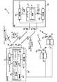
図1は、本開示の一実施形態に係る、選択ビーム減衰を伴うオポチュニスティックビーム形成を採用した通信システム20を概略的に示したブロック図である。システム20は、あらゆる好適な通信規格又はプロトコルに従って、動作する。図に示した例では、システム20は、上記したLTE又はLTE−A規格に従って動作する。これに替えて、以下に記載する技術は、その他の好適な通信規格又はプロトコルに従って動作するシステムにも使用することができ、例えば、IEEE802.16(WiMAXとも称される)、広帯域符号分割多元接続(WCDMA)、及びGSM(Global System for Mobile communications)に従って動作してもよい。 FIG. 1 is a block diagram that schematically illustrates a
システム20は、複数の受信機に信号を送信する複数の送信機を備える。本例では、送信機は、LTE又はLTE−A基地局(eNodeB)24に実装され、受信機としては、LTE又はLTE−A準拠の携帯端末(UE)28を含む。図1には、簡略的に示すために、3つのeNodeB及び1つのUEが描かれているが、一般的な実際のシステムでは、多数のeNodeB及びUEが含まれる。以下に記載される実施形態では、eNodeBからUEへのダウンリンク伝送を例にとって説明されるが、ある通信システムでは、開示される技術は、アップリンクにも好適に適用される。 The
eNodeB24は、1以上のアンテナ36を介してUE28へとダウンリンク信号を送信するダウンリンク送信機32を含む。(図1では、簡略化のため、eNodeBの内部構造は、1つのeNodeBについてのみ詳細に示されている。システム内のその他のeNodeBは、典型的には同様な構造を備えている。)所定の時間に、システム20内のeNodeB24は、M個のダウンリンク無線周波数(RF)送信ビームを送信し、これらの送信ビームによって、それぞれデータ含むダウンリンク信号がUE28へと送信される。送信ビーム(簡略化のため、以下、ビームと称する)は、典型的には、指向性を有する。 The
一実施形態において、指向性送信ビームは、2つ以上のアンテナ36を使用して、1つのeNodeBによって生成される。または、指向性ビームは、同じ信号を同時に送信する複数のeNodeBによって生成され、この場合、eNodeBは、1以上のアンテナ36を使用する。1つの所定のビームを生成する複数のeNodeBからなるグループは、以下、クラスタと呼ばれる。以下の説明では、ビームはそれぞれ、複数のeNodeBからなるクラスタによって伝送されたものとして考える。ビームが1つのeNodeBによって伝送される場合には、クラスタは、1つのeNodeBのみを含むとして考える。 In one embodiment, the directional transmit beam is generated by one eNodeB using two or
送信ビームはそれぞれ、データを伝送する指向性RF信号を含む。各ビームは、複数のアンテナ36によって構成されるセットから、同じデータを伝送する信号を送信させることによって生成される。複数のアンテナは1以上のeNodeBに属し、セットにおける複数のアンテナに対して、それぞれ倍数的な重み付け(ウェイト)を適用する。一実施形態において、ビームが送信される方向は、アンテナに適用される重み(ウェイト)を変更することによって変更される。このアクションは、ビームステアリングと称される。 Each transmit beam includes a directional RF signal that carries data. Each beam is generated by transmitting a signal transmitting the same data from a set constituted by a plurality of
i番目のビームに適用するビームステアリング(すなわち、i番目のビームの送信に参加する異なる複数のアンテナに適用される重み)は、
所定の時間に、システム20によって送信されるM個のビームのセットを、本明細書では、ビーム設定と呼ぶ。ある実施形態では、システム20は、周期的な時間間隔で、ビーム設定を変更する。すなわち、eNodeB24は、時間及び空間的に変化する複数の送信ビームを送信する。LTE又はLTE−Aシステムでは、例えば、ビーム設定は、各送信時間間隔(TTI)毎、複数のTTI毎、又はその他の好適な周期で、変更されてもよい。 The set of M beams transmitted by the
ある実施形態では、eNodeBは、複数のeNodeB間での調整が行われたパターンに従って、時間及び空間においてビームを変化させる。別の実施形態では、各eNodeBは、その他のeNodeBとの間の調整を行うことなく、ビームを変化させる。更なる別の実施形態では、eNodeBは、パターンを使用しなくてもよい。しかしながら、典型的には、複数のeNodeBは互いに、OFDMシンボルタイミングを同期させる。 In one embodiment, the eNodeB changes the beam in time and space according to a pattern that is coordinated between multiple eNodeBs. In another embodiment, each eNodeB changes the beam without making adjustments with other eNodeBs. In yet another embodiment, the eNodeB may not use a pattern. However, typically, multiple eNodeBs synchronize OFDM symbol timing with each other.
以下に説明するように、ある実施形態では、ビーム設定のパターンは予め定められており、別の実施形態では、パターンは、擬似的にランダムである。周期的なパターンを使用する場合には、eNodeBは、そのローカルビーム設定(すなわち、自身のアンテナ36に対応するウェイトベクトル要素)をある周期的な間隔で変更してもよく、その周期は、別のeNodeBの周期間隔と同じであってもよいし、異なっていてもよい。典型的には、ビーム設定は、十分に多様性を有するように選択され、各UEが、高い信号強度及び干渉が低いビーム設定を発見できるようにする。ある実施形態では、複数のeNodeBからなるクラスタは、最適化プロセスを使用して、ビームを生成及び変化させる。最適化プロセスは、しばしばUEには知られない態様で行われる。 As described below, in one embodiment, the beam setting pattern is predetermined, and in another embodiment, the pattern is pseudo-random. When using a periodic pattern, the eNodeB may change its local beam setting (ie, the weight vector element corresponding to its antenna 36) at certain periodic intervals, It may be the same as or different from the periodic interval of eNodeB. Typically, the beam settings are selected to be sufficiently diverse so that each UE can find a beam setting with high signal strength and low interference. In one embodiment, a cluster of multiple eNodeBs uses an optimization process to generate and change the beam. The optimization process is often performed in a manner that is unknown to the UE.
一実施形態では、所定のUE28へのデータ送信を準備する時に、システム20は、どのビームを介して何時データを送信するかを選択する。さらに、幾つかの実施形態では、システム20は、別のビームとの干渉を低減させるべく1以上のビームを減衰させることを決定する。本開示の一実施形態において、これらのスケジューリング及び減衰の決定は、本明細書に記載される方法を使用してUEから提供されるフィードバックに基づいて行われる。 In one embodiment, when preparing for data transmission to a given UE 28, the
eNodeB24は、UEから(アンテナ36を介して、又は、図示しない別の受信アンテナを介して)アップリンク信号を受信するアップリンク受信機40を含む。具体的には、受信機40は、UEからフィードバックを受信し、それにより、eNodeBがスケジューリング及び減衰の判断を行うことが可能となる。ある実施形態では、フィードバックは、UEからの1以上のビームを介して伝送を受信するという明示的な要求、及び/又は1以上のビームを減衰するという明示的な要求を含む。これに替えて、フィードバックは、1以上の受信されたビームにおいてUEが計測した信号品質測定結果を含む。この情報を使用して、eNodeBは、どのビームを送信し、どのビームを減衰するかを決定する。 The
eNodeB24は更に、eNodeBのオペレーションを管理する制御部44を備える。制御部44は、送信機32から送信されるビーム設定のパターンを生成するビームパターン生成器48を備える。一実施形態において、複数の異なるeNodeB24のビームパターン生成器48は、互いにパターン生成を調整及び同期させる。 The
ある実施形態では、制御部44は、送信されたビームの1以上を減衰させるよう送信機32を設定するビーム減衰モジュール52を含む。減衰させるべきビームは、UE28から受信されたフィードバックに基づいて選択される。制御部44は更に、異なる複数のビームを介したデータの送信をスケジュールするスケジューラ56を含む。具体的には、スケジューラ56は、何時(例えば、どのTTIの間に)、どのビーム上でデータをUEそれぞれに送信するべきかを決定する。ある実施形態では、制御部44は(例えば、スケジューラ56を使用して)、UEそれぞれに送信を行うのに使用される適切な変調及びエラー修正コーディングスキームを選択する。 In some embodiments, the
UE28はそれぞれ、1以上のアンテナ60を使用して、ダウンリンク送信ビームを受信する。ダウンリンク受信機64は、異なるビームを介して伝送された信号を受信及びデコードし、ダウンリンクデータを再構築及び出力する。加えて、受信機64は、各ビームにおける信号品質を測定する。一実施形態において、受信機64は、例えば、各ビームにおける信号対ノイズ比(SNR)の測定、又はその他の好適な信号品質測定を行う。 Each UE 28 receives downlink transmission beams using one or
図1に示すように、一実施形態において、UE28は、UEのオペレーションを制御及び管理するプロセッサ72を備える。ある実施形態では、プロセッサ72は、UEからeNodeBへと送信されるフィードバックを計算するフィードバック計算モジュール76を有する。一実施例では、モジュール76は、ダウンリンク受信機64によって異なる複数のビームについて実行された信号品質測定に基づいて、フィードバック内容を決定する。ある実施形態では、フィードバックは、(1)UEがダウンリンク伝送を受信するのに望ましいと考えている1以上のビーム、(2)UEにおけるダウンリンク受信と干渉を引き起こしている1以上のビーム、及び/又は、(3)送信されたビームの1以上を減衰させる特定の要求、を示す情報を含む。 As shown in FIG. 1, in one embodiment, the UE 28 comprises a
この種のフィードバックにより、eNodeBは、好ましいビームにダウンリンクデータをスケジュールすることができ、干渉しているビームを減衰させることができる。選択基準及びフィードバックスキームの例を幾つか、以下に記載する。UE28は、アップリンク信号をeNodeBへと送信するアップリンク送信機68を備える。具体的には、アップリンク送信機は、モジュール76によって生成されたフィードバックを送信する。 This type of feedback allows the eNodeB to schedule downlink data on the preferred beam and attenuate the interfering beam. Some examples of selection criteria and feedback schemes are described below. The UE 28 includes an
図1に示すシステム構成は、コンセプトを明確にする目的から示されているものであり、単純化された構成例である。別の実施形態では、その他の好適なシステム構成を使用することができる。一実施形態において、eNodeB24及びUE28の異なる複数の構成要素を、1以上の特定用途向け集積回路(ASIC)及び/又はフィールドプログラマブルゲートアレイ(FPGA)のような専用ハードウェアを使用して実装してもよい。これに替えて、一実施形態では、eNodeB及びUEの構成要素の一部を、汎用ハードウェア又はファームウェアで実行されるソフトウェアを使用して、又は、ハードウェア要素及びソフトウェア要素の組み合わせを使用して実装してもよい。 The system configuration shown in FIG. 1 is shown for the purpose of clarifying the concept, and is a simplified configuration example. In other embodiments, other suitable system configurations can be used. In one embodiment, different components of
ある実施形態では、制御部44及びプロセッサ72は、本明細書に記載される機能を提供するべくコンピュータ命令を実行するソフトウェアにプログラムされる汎用プロセッサを含むが、これらは、専用ハードウェアに実装されてもよい。ソフトウェア命令を、例えば、ネットワークを介して、電子的な形でプロセッサにダウンロードしてもよい。これに替えて又はこれに加えて、ソフトウェア命令を、磁気、光又は電子メモリのような有形倍体に供給及び/又は格納してもよい。ある実施形態では、UE28の要素の一部又は全て、及び/又はeNodeB24の要素の一部又は全てを、チップセットに形成してもよい。開示する技術を説明するのに必須でないUE及びeNodeB要素、例えば、様々な無線周波数(RF)要素等は、簡略化のため図1では省略されている。 In some embodiments,
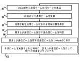
図2は、本開示の一実施形態に係る、選択ビーム減衰を伴うオポチュニスティックビーム形成を使用した通信方法を概略的に示したフローチャートである。この方法では、まず初めに、ビーム送信オペレーション80において、eNodeB24は、複数のRF送信ビームの1パターンを送信する。ビーム受信オペレーション84において、UE28は、ダウンリンク受信機64を使用して、複数のビームのうちの少なくとも一部を受信する。品質受信オペレーション88では、受信機64は、受信されたビームそれぞれにおける信号品質を測定する。受信機64は、異なる複数のビームの信号品質測定値を、プロセッサ72に報告する。 FIG. 2 is a flowchart schematically illustrating a communication method using opportunistic beamforming with selective beam attenuation according to an embodiment of the present disclosure. In this method, first, in the beam transmission operation 80, the
ビーム特定オペレーション92では、プロセッサ72は、信号品質測定値に基づいて、1以上の好ましいビーム及び1以上の干渉ビームを特定する。フィードバックオペレーション96において、アップリンク送信機68は、望ましいビーム及び干渉ビームを示すフィードバックをeNodeBへと送信する。スケジューリング及び減衰オペレーション100では、eNodeB24は、受信されたフィードバックに基づいて、UEへの更なる伝送をスケジュールする。さらに、eNodeBは、UEからのフィードバックに基づいて、1以上のビームを選択及び減衰させる。所定のクラスタ内のeNodeBは、互いにビーム設定パターンを調整しているか否かに関わらず、典型的には、スケジュール決定において協働する。 In
UE28は、好適に、様々な態様で、フィードバックを計算及び報告する。例えば、一実施形態において、UEは、その他全てのビームがアクティブであると仮定(及び干渉が引き起こされている可能性があると仮定)して、各ビームにおけるSNRを計算する。加えて、一実施形態において、UEは、1以上の最も干渉を引き起こしているビームがオフ状態とされたと仮定して、各ビームにおけるSNRを計算する。ある実施形態では、各UEには、複数のビームからなる1セットが予め割り当てられ、これらを、UEのサービングビームと称する。所定のUEのサービングビームは、1つのeNodeB、複数のeNodeBからなる1つのクラスタ又は複数のクラスタによって生成されてもよい。一実施形態において、UEは、自身に割り当てられたサービングビームのみを考慮して(すなわち、サービングビーム以外のビームによる干渉の可能性を考慮せずに)、信号品質を測定し、フィードバックを計算する。 The UE 28 preferably calculates and reports feedback in various ways. For example, in one embodiment, the UE calculates the SNR in each beam assuming all other beams are active (and assuming that interference may have been caused). In addition, in one embodiment, the UE calculates the SNR in each beam, assuming that the one or more most causing beam is turned off. In one embodiment, each UE is pre-assigned a set of beams, which are referred to as the UE's serving beam. The serving beam for a given UE may be generated by one cluster or multiple clusters of one eNodeB, multiple eNodeBs. In one embodiment, the UE measures the signal quality and calculates the feedback considering only the serving beam assigned to it (ie, not considering the possibility of interference by beams other than the serving beam). .
一実施例において、UEは、m≧1であるm個の強いビームを報告することによって、最も望ましい複数のビームをフィードバックで示す。ある実施形態では、UEは、これらのビームで測定されたSNRについても報告する。ある実施形態では、UEは、望ましいビームで送信を行うν≧1であるν個の望ましい送信時間を特定する。一実施形態において、UEは、これらの送信時間において達成可能なSNRと共に、望ましい送信時間をフィードバックで報告する。 In one embodiment, the UE indicates in feedback the most desirable beams by reporting m strong beams where m ≧ 1. In some embodiments, the UE also reports on the SNR measured with these beams. In an embodiment, the UE identifies ν desired transmission times for which ν ≧ 1 to transmit with the desired beam. In one embodiment, the UE reports the desired transmission time in feedback along with the SNR achievable at these transmission times.
ある実施形態では、UEは、望ましいビームの受信と大きな干渉を起こしている1以上のビームを特定する。例えば、一実施形態において、UEは、減衰させる(例えば、消す)ことによって、望ましいビームにおけるSNRを最も改善することができる1以上のビームを特定する。一実施例において、UEは、最も強い干渉を起こしているμ≧1であるμ個のビームを報告する。別の実施例では、干渉ビームを減衰させることによって期待されるSNRの改善度を報告する。別の実施例では、UEは、減衰させることによって、望ましいビームにおけるSNRを少なくともΔdB改善するであろう干渉ビームの全てを報告する。 In some embodiments, the UE identifies one or more beams that are causing significant interference with the reception of the desired beam. For example, in one embodiment, the UE identifies one or more beams that can best improve the SNR in the desired beam by attenuating (eg, extinguishing). In one embodiment, the UE reports μ beams with μ ≧ 1 causing the strongest interference. In another embodiment, the expected improvement in SNR by attenuating the interference beam is reported. In another embodiment, the UE reports all of the interfering beams that will attenuate at least ΔdB the SNR in the desired beam by attenuating.
ある実施形態では、2つ以上のビームからなるグループを所定のUEに通知し、UEは、グループ内の異なる複数のビーム間における干渉を(例えば、異なる複数のビームの信号をデコードし、一方の信号から他の信号を差し引くことにより)キャンセルするメカニズムを含む。これらの実施形態において、望ましいビーム及び干渉ビームを特定する時に、UEは、この干渉を内部でキャンセルできると仮定して、グループ内におけるビーム間の干渉は考慮しない。これに加えて又はこれに替えて、UEは、その他の好適な態様で、望ましいビーム及び干渉ビームを特定してもよい。 In an embodiment, a group of two or more beams is notified to a given UE, and the UE can detect interference between different beams in the group (eg, decode signals of different beams, Includes a mechanism to cancel (by subtracting other signals from the signal). In these embodiments, when identifying the desired and interfering beams, the UE does not consider the inter-beam interference within the group, assuming that the interference can be canceled internally. In addition or alternatively, the UE may identify the desired and interfering beams in other suitable manners.
UEにおける受信機64は、異なる複数のビームにおける信号品質を、いかなる好適な方法で測定してもよい。例えば、一実施形態において、所定のビームを介して送信されるダウンリンク信号は、そのビームに固有のパイロットシンボルを含む。受信機64は、ビームのパイロットシンボルを使用して、達成可能なSNRを見積もることによって、所定のビームにおける信号品質を測定する。例えば、受信機は、eNodeB及びUEの間のチャネル応答を、パイロット信号を使用して推定してもよい。推定したチャネル及び既知のビームステアリングベクトル(ウェイトベクトル)に基づいて、UEは、そのビームにおいて達成可能なSNRを見積もる。 The receiver 64 at the UE may measure the signal quality in different beams in any suitable manner. For example, in one embodiment, the downlink signal transmitted via a given beam includes pilot symbols specific to that beam. The receiver 64 measures the signal quality in a given beam by estimating the achievable SNR using the pilot symbols of the beam. For example, the receiver may estimate the channel response between the eNodeB and the UE using a pilot signal. Based on the estimated channel and the known beam steering vector (weight vector), the UE estimates the achievable SNR for that beam.
システム20のeNodeB24は、異なる複数のUE28から上記のフィードバックを受信し、このフィードバックに基づいて様々な方法で送信ビームを設定する。eNodeBは、例えば、何時及びどの1つの又は複数のビームを介して各UEへ送信を行うか、何時及びどの干渉ビームを減衰させるか、減衰させるビームに適用する減衰のレベルはどのくらいか、所定のUEへの伝送にどの変調及びコーディングスキームを使用するのか、といった関連する事項の決定を好適に行う。これらの決定を行う際には、eNodeBは、スケジュール間隔それぞれにおける特定の品質測定値を取得するのを試みてもよい。例えば、最大システムスループットのような複数のUEの間に公平で比例する基準、又はその他の好適な品質条件を、最適化に使用することができる。 The
一実施形態において、eNodeBの決定は、クラスタ毎に個別に及び独立して行われる。様々な実施形態において、各クラスタの複数のeNodeBは、受信したフィードバックを共有し、ビーム設定パターン及び決定内容を調整するために、互いに通信を行う。これに替えて、決定は、システム20全体に対する中央プロセッサ(図示せず)によって行われてもよい。この実施形態の場合、異なる複数のeNodeBは、中央プロセッサと通信を行い、受信したフィードバックを報告し、設定命令をプロセッサから受信する。一実施例において、中央プロセッサは、ビームそれぞれについて(1)そのビームを送信すべきか否か(2)ビームが向けられるUE(複数のビームを、同じUEに対して向けることができる)、及び(3)ビームを送信するのに使用する変調及びコーディングスキーム、についての指示をeNodeBに送信する。 In one embodiment, eNodeB determination is performed individually and independently for each cluster. In various embodiments, multiple eNodeBs in each cluster communicate with each other to share received feedback and adjust beam setting patterns and decisions. Alternatively, the determination may be made by a central processor (not shown) for the
様々な実施形態において、所定のビームの減衰は、様々な態様で好適に実行される。ある実施形態では、eNodeBは、干渉するビーム全ての送信を停止させる。別の実施形態では、eNodeBは、そのビームの送信電力を、通常レベルよりも一定量分下げる。ある実施形態では、減衰係数は、10−30dBの単位が使用される。別の実施形態では、望ましいビームにおける許容SNRを可能とするのに、小さな減衰係数、例えば、3−6dBが好適である。更なる別の実施形態では、その他の好適な減衰係数を使用することができる。ある実施形態では、eNodeBは、減衰するビームにそれぞれ適用する実際の減衰レベルを選択する。 In various embodiments, the attenuation of a given beam is suitably performed in various ways. In some embodiments, the eNodeB stops transmitting all interfering beams. In another embodiment, the eNodeB reduces the transmit power of the beam by a certain amount below the normal level. In some embodiments, the attenuation coefficient is in the unit of 10-30 dB. In another embodiment, a small attenuation factor, eg, 3-6 dB, is suitable to allow an acceptable SNR in the desired beam. In still other embodiments, other suitable attenuation factors can be used. In one embodiment, the eNodeB selects the actual attenuation level to apply to each beam that is attenuated.
また、ある実施形態では、減衰されるビームを、別のUEへの信号送信に使用する。例えば、第1UEへの送信と干渉しないように3−6dB又はそれ以上減衰されたビームは、第2UEへの信号送信を行うのに十分強い送信電力を有している。ある実施形態では、様々なビームの望ましい減衰係数を決定する時に、eNodeBはこの効果を考慮して、システム全体のスループットを改善させるようにしてもよい。 In some embodiments, the attenuated beam is used for signal transmission to another UE. For example, a beam that is attenuated 3-6 dB or more so as not to interfere with transmission to the first UE has sufficiently strong transmission power to perform signal transmission to the second UE. In some embodiments, when determining the desired attenuation factors for the various beams, the eNodeB may take this effect into account to improve the overall system throughput.
ある実施形態では、所定のUEは、eNodeBに、干渉ビームを報告しないようにしてもよい。例えば、一実施形態において、UEは、干渉が相対的に小さい場合には、干渉ビームを報告しないことを選択してもよい。別の例では、UEは、eNodeBから、(例えば、特定のシステム構成において)干渉ビームを報告しないように要求されてもよい。 In some embodiments, a given UE may not report an interference beam to the eNodeB. For example, in one embodiment, the UE may choose not to report an interfering beam if the interference is relatively small. In another example, the UE may be requested not to report an interfering beam from the eNodeB (eg, in certain system configurations).
上記したように、eNodeB24は、特定のパターンに従って、時間の経過と共にビーム設定を変更させる。ある実施形態では、ビーム設定は、相対的にゆっくり変更される。ある場合には、数TTIに1回(例えば、10個のTTIに1回又はそれよりもゆっくり)よりも遅い割合でのビーム設定の変更を、遅いとみなす。別の場合には、1つのTTIに1回のビーム設定変更を、遅いとみなす。これらの実施形態では、システムは、フィードバックサイクルを完結する(すなわち、UEによって信号品質を測定しフィードバックを報告して、フィードバックに応答してeNodeBによりダウンリンク信号を送信し、このダウンリンク信号をUEで受信する)のに十分な長さの時間を有し、この期間、同じビーム設定が有効である。 As described above, the
ある実施形態では、ビーム設定パターンは予め既知であり、UEは、所定のビーム設定について信号品質を測定し、フィードバックを報告する、そして、その後あるタイミングにおいて再び品質測定を行う。すなわち、UEは、現在のビーム設定における特定のビームによって生じている別のビームへの干渉を測定することができ、このビーム設定が再び将来使用される時に、この干渉が発生すると予測することができる。一実施形態において、eNodeBは、このフィードバックを、スケジューリングの決定、及びこのビーム設定が将来発生する時のビームの減衰の決定に使用する。このような技術により、システムは、例えば、フィードバックプロセスに関係する遅延を補償することができる。この種の技術は、ビーム設定が速く変化する、例えば、1つのTTI毎に変化するような場合に好適に使用することができ、パターンがゆっくり変化する場合にも適用することができる。 In some embodiments, the beam setting pattern is known in advance, and the UE measures signal quality for a given beam setting, reports feedback, and then makes quality measurements again at some timing. That is, the UE can measure the interference to another beam caused by a particular beam in the current beam setting and can predict that this interference will occur when this beam setting is used again in the future. it can. In one embodiment, the eNodeB uses this feedback to determine scheduling and beam attenuation when this beam setup occurs in the future. Such techniques allow the system to compensate for delays associated with, for example, the feedback process. This type of technique can be suitably used when the beam setting changes quickly, for example, every TTI, and can also be applied when the pattern changes slowly.
図3は、本開示の一実施形態に係る、送信ビームの調整されたパターンを使用した伝送プロトコルを示した図である。この例では、2つのeNodeBが示されており、それぞれが1つのビームを送信する。本例において、2つのeNodeBは、1つのTTI毎に、ビーム設定を変更する。第1eNodeBは、L1個のTTI期間を有する周期的なビーム設定のパターンを適用する。このパターンにおけるウェイトベクトルは、
各TTIにおいて、eNodeBは、上記したように、UEが2つのビームにおける信号品質を測定しフィードバックを計算することが可能となるパイロット信号を送信する。2つのパターンが周期的であることから、ウェイトベクトル
本実施形態では、所定のUEは、様々な種類のフィードバックを報告するように設定されてもよく、例えば、パターンにおける次の5つのTTIのうち、最も品質が良いTTIのID、最も高いSNRを達成しているビームのID、最も品質が良いTTI期間における最も品質が良いビームの達成可能SNR、及び/又はその他のビームが減衰されたと仮定した場合の最も品質が良いTTI期間における最も品質が良いビームの達成可能なSNR等のフィードバックが考えられる。一実施形態では、このフィードバックに基づいて、2つのeNodeBは協働して、望ましいスケジューリングポリシーを決定する。例えば、このポリシーは、1以上のTTIの間に、2つのビームのうちの1つを減衰することに関する。L1及びL2が公約数を有さない場合には、例えば、2つのeNodeBは、L1×L2個の可能性のあるビーム設定について、スケジューリングポリシーを選択する。In this embodiment, a given UE may be configured to report various types of feedback, for example, the highest quality TTI ID and highest SNR among the next five TTIs in the pattern. The ID of the beam being achieved, the achievable SNR of the best quality beam in the best quality TTI period, and / or the best quality in the best quality TTI period assuming the other beams are attenuated. Feedback such as the achievable SNR of the beam is conceivable. In one embodiment, based on this feedback, the two eNodeBs work together to determine the desired scheduling policy. For example, this policy relates to attenuating one of two beams during one or more TTIs. If L1 and L2 do not have a common divisor, for example, the two eNodeBs select a scheduling policy for L1 × L2 possible beam settings.
図4は、本開示の一実施形態に係る、送信ビームの調整されたパターンを使用した伝送プロトコルを示した図である。本例において、システムは、eNodeB1、eNodeB2及びeNodeB3と称される3つのeNodeBを含む。eNodeB1は、2つの送信アンテナを有し、2つのビームを送信する。eNodeB2及びeNodeB3は、それぞれ1つの送信アンテナを有し、合同で2つのビームを送信する。したがって、B1=B2={1}、B3=B4={2,3}、であり、全てのウェイトベクトルの長さが2となる。FIG. 4 is a diagram illustrating a transmission protocol using an adjusted pattern of transmission beams according to an embodiment of the present disclosure. In this example, the system includes three eNodeBs called eNodeB1 , eNodeB2 and eNodeB3 . eNodeB1 has two transmit antennas and transmits two beams. eNodeB2 and eNodeB3 each have one transmission antenna and jointly transmit two beams. Therefore, B1 = B2 = {1}, B3 = B4 = {2, 3}, and the length of all weight vectors is 2.
図4の例において、eNodeBは、数個のTTI毎にビーム設定(ウェイトベクトル)を変更する、すなわち相対的にゆっくり変更する。ビーム設定が一定である期間は、TBと表されている。この構成において、ビーム設定のパターンは、周期的又は決定論的である必要はない。例えば、パターンは、疑似ランダムパターンであってもよい。In the example of FIG. 4, the eNodeB changes the beam setting (weight vector) every several TTIs, that is, changes relatively slowly. Period is the beam set is constant, is represented as TB. In this configuration, the beam setting pattern need not be periodic or deterministic. For example, the pattern may be a pseudo random pattern.
図4の構成において、TBの最初の数個のTTIの間(図では、DATAと記されている)は、eNodeBは、現在有効なビーム設定を使用して、データシンボル及びパイロットシンボルを送信する。"PLT"と記された1つのTTI期間の間は、eNodeBは、現在有効なビーム設定を使用してデータの送信は続けるが、パイロットシンボルについては、次のTB期間のビーム設定を使用して送信するように切り替える。ここで使用されるパイロットシンボルは、専用パイロットシンボルを含む。このTTIの間、UEは、次のTB期間に適用可能な信号品質測定を実行すると同時に、現在有効なビーム設定を使用してデータの受信を継続するよう設定されている。典型的なUEは、ビームそれぞれを使用して、達成可能なSNRを測定する。別の実施形態では、"PLT"のTTI期間に使用されるパイロットシンボルは、全てのウェイトベクトルがUEに対して既知であると仮定して、共通パイロットシンボルを含む。In the configuration of FIG. 4, (in the figure, labeled DATA) during the first few TTI of TB is eNodeB uses the currently active beam set, transmit the data symbols and pilot symbols To do. During one TTI period labeled "PLT" is eNodeB is transmitting data continue using the current effective beam setting, the pilot symbols using a beam set of the next TB period Switch to send. The pilot symbols used here include dedicated pilot symbols. During this TTI, UE, at the same time to perform the applicable signal quality measurement to the next TB period, it is set to continue to receive data using the current valid beam settings. A typical UE uses each beam to measure the achievable SNR. In another embodiment, the pilot symbols used in the “PLT” TTI period include common pilot symbols, assuming that all weight vectors are known to the UE.
FBKと記されたTTIの間は、eNodeBは、現在有効なビーム設定を使用してデータ送信を続けると同時に、UEからフィードバックを受信する。計測に基づいて計算されるフィードバックは、"PLT"TTI期間に実行されているので、次のTB期間に適用することができる。eNodeBは、次のTB期間の時に、このフィードバックを適用する(例えば、スケジューリングの決定及びビーム減衰を行う)。During the TTI marked FBK, the eNodeB receives data from the UE while continuing to transmit data using the currently valid beam settings. Feedback is calculated based on the measurements, so they run as "PLT" TTI period can be applied to the following TB period. eNodeB, when the nextT B period, applying the feedback (e.g., make a decision and beam attenuation scheduling).
図4の例において、"FBK"TTIは、TB期間における最後のTTIであり、"PLT"TTIはそれの1つ前のTTIである。別の実施形態では、"PLT"及び"FBK"TTIは、TB期間におけるその他の好適な位置に配置され、それにより、フィードバックを計算及び送信するのに十分な時間を確保し、それを、次のTB期間において適用する。In the example of FIG. 4, "FBK" TTI is the last TTI inT B period, "PLT" TTI is the one before it TTI. In another embodiment, "PLT" and "FBK" TTI is disposed other suitable location in the TB period, thereby ensuring a sufficient time to calculate and send feedback, it, applied in the nextT B period.
ある実施形態では、"FBK"TTI期間においてUEによって送信されるフィードバックは、例えば、4つの可能性のあるビームのうち最も品質が良好な2つのビームのID、選択されたビームの組をそれぞれ使用した時の達成可能なSNR、その他の3つのビームのうちの1つが減衰されていると仮定した場合の最も良好なビームにおける最も良好なSNR、及び/又は減衰させるのが望ましいビームのIDを含む。 In one embodiment, the feedback sent by the UE during the “FBK” TTI period uses, for example, the IDs of the two best quality beams of the four possible beams, each selected set of beams. Achievable SNR at the time, the best SNR in the best beam assuming one of the other three beams is attenuated, and / or the ID of the beam that is desired to be attenuated .
UEからこのフィードバックを受信した後、3つのeNodeBは、次のTB期間に適用する最も良好なスケジュールスキームを決定する。減衰のためだけにeNodeBを協働させることが必要だった図3の例とは対照的に、図4の例では、eNodeB2及びeNodeB3は、2つの共通のビームを介して同じデータを送信することから、スケジュールリングスキーム全体を一緒に実行する。また、本例では、同じTB期間の間に、スケジューリングが可能な複数のTTIが存在する。したがって、この実施形態では、eNodeBは、同じビーム設定を使用して幾つかのスケジューリングの決定を行うよう構成されている。After receiving the feedback from the UE, 3 single eNodeB determines the best schedule scheme to be applied to the next TB period. In the example of FIG. 4, eNodeB2 and eNodeB3 transmit the same data via two common beams, as opposed to the example of FIG. 3 where it was necessary to collaborate with eNodeB only for attenuation. Therefore, the entire scheduling scheme is executed together. Further, in this embodiment, during the same TB period, scheduling a plurality of TTI are present as possible. Thus, in this embodiment, the eNodeB is configured to make several scheduling decisions using the same beam settings.
ある実施形態では、TB期間は相対的に長く、この期間における通信チャネルにおける変更は無視される。このような実施形態において、UEは、TB期間の間に計算した更なるフィードバックを送信し、スケジューリングの決定が更に改善されるようにする。これに加えて又はこれに替えて、予測技術を好適に使用して、フィードバックの遅延を補償してもよい。In some embodiments, TB period is relatively long, changes in the communication channel during this period are ignored. In such embodiments, UE sends a further feedback calculated during the TB period, a scheduling decision has to be further improved. In addition or alternatively, prediction techniques may be suitably used to compensate for feedback delays.
ある実施形態では、図4のスキームをその他の種類のフィードバックと組み合わせる、又はeNodeBが利用可能なその他の情報と組み合わせる。eNodeBは、ウェイトベクトルを自由に選択できるが、あるUEにとってより望ましいと考えられる送信ビームを生成するために、更なるチャネル情報を使用することができる。一実施形態において、ウェイトベクトルの選択は、ダウンリンク性能の劣化が発生しない又はほとんど発生しないように行われる。 In some embodiments, the scheme of FIG. 4 is combined with other types of feedback or with other information available to the eNodeB. The eNodeB is free to choose a weight vector, but can use additional channel information to generate a transmit beam that may be more desirable for certain UEs. In one embodiment, the selection of weight vectors is performed such that there is little or no degradation in downlink performance.
上記した実施形態では、システム20の全てのeNodeB24によって、システム20に割り当てられたスペクトル全体に渡って、開示された技術が実行される。しかしながら、一般的に、開示された技術は、この種のeNodeB全てによる実行に限定されない。別の実施形態では、例えば、開示された技術は、システム20におけるeNodeBの一部のみを使用して実行されてもよく、及び/又はシステムに割り当てられたスペクトルの一部のみにおいて実行されてもよい。 In the embodiment described above, the disclosed technique is performed by all
上記の実施形態は、例として示されたに過ぎず、本発明は、上記の特定の実施形態に限定されない。本発明の範囲は、上記した様々な特徴の組み合わせ及びサブコンビーネーション、並びに、本明細書を読む当業者が想到する従来技術に開示されていない改良及び変更を含む。 The above embodiments have been presented by way of example only, and the present invention is not limited to the specific embodiments described above. The scope of the present invention includes combinations and sub-combinations of the various features described above, as well as improvements and modifications not disclosed in the prior art that will occur to those of ordinary skill in the art reading this specification.
Claims (24)
Translated fromJapanese前記第1送信ビームが前記第2送信ビームの受信と干渉を引き起こしていることを特定する段階と、
1以上の送信機が、前記第2送信ビームの送信の間に前記第1送信ビームを減衰するように、前記受信機から前記1以上の送信機へとフィードバックを送信する段階と
を備え、
前記第1送信ビームは、周期的に設定された重み付け関数を用いて減衰され、
現在の前記重み付け関数を用いて、前記第1送信ビームと前記第2送信ビームとの将来の干渉が予測される通信方法。Receiving, at a receiver, a plurality of radio frequency (RF) transmit beams that vary temporally and spatially and include at least a first transmit beam and a second transmit beam from a group including two or more transmitters;
Identifying that the first transmit beam is causing interference with reception of the second transmit beam;
One or more transmitters sending feedback from the receiver to the one or more transmitters to attenuate the first transmit beam during transmission of the second transmit beam; and
The first transmit beam is attenuated using a periodically set weighting function;
A communication method inwhich future interference between the first transmission beam and the second transmission beam is predicted using the current weighting function .
前記第1送信ビームが前記第2送信ビームの受信と干渉を引き起こしていることを特定する段階と、
1以上の送信機が、前記第2送信ビームの送信の間に前記第1送信ビームを減衰するように、前記受信機から前記1以上の送信機へとフィードバックを送信する段階と
を備え、
複数の基地局が、前記第1送信ビームと前記第2送信ビームとを介して同じデータを送信する通信方法。Receiving, at a receiver, a plurality of radio frequency (RF) transmit beams that vary temporally and spatially and include at least a first transmit beam and a second transmit beam from a group including two or more transmitters;
Identifying that the first transmit beam is causing interference with reception of the second transmit beam;
One or more transmitters sending feedback from the receiver to the one or more transmitters to attenuate the first transmit beam during transmission of the second transmit beam;
With
A communication method inwhich a plurality of base stations transmit the same data via the first transmission beam and the second transmission beam .
前記フィードバックを送信する段階は、前記第2送信ビームを介して、前記次に続く伝送を受信する要求を送信する段階を含む請求項1から3のいずれか一項に記載の通信方法。Identifying that the second transmit beam is suitable for receiving a transmission to a subsequent receiver;
4. The communication method accordingto claim 1, wherein the step of transmitting the feedback includes the step of transmitting a request to receive the subsequent transmission via the second transmission beam. 5.
前記フィードバックを送信する段階は、前記将来の発生時に、前記1以上の送信機に前記第1送信ビームを減衰させることを含む請求項1から3のいずれか一項に記載の通信方法。Identifying that the first transmit beam is causing the interference includes predicting interference in future occurrences of the first transmit beam and the second transmit beam;
The communication method according toany one of claims 1to 3 , wherein the step of transmitting the feedback includes attenuating the first transmission beam to the one or more transmitters in the future occurrence.
前記フィードバックを送信する段階は、前記望ましい期間に、前記1以上の送信機に前記第1送信ビームを減衰させる段階を含む請求項8に記載の通信方法。Selecting a desired time period for receiving a signal via the second transmit beam;
9. The communication method of claim8 , wherein transmitting the feedback comprises attenuating the first transmit beam to the one or more transmitters during the desired period.
前記第1送信ビームが前記第2送信ビームの受信と干渉を引き起こしていることを特定し、1以上の送信機が前記第2送信ビームの送信の間に前記第1送信ビームを減衰するように、前記1以上の送信機へとフィードバックを送信させるプロセッサと
を備え、
前記第1送信ビームは、周期的に設定された重み付け関数を用いて減衰され、
現在の前記重み付け関数を用いて、前記第1送信ビームと前記第2送信ビームとの将来の干渉を予測する通信装置。A receiver for receiving a plurality of radio frequency (RF) transmit beams that vary temporally and spatially and include at least a first transmit beam and a second transmit beam from a group including two or more transmitters;
Identifying that the first transmit beam is causing interference with reception of the second transmit beam, such that one or more transmitters attenuate the first transmit beam during transmission of the second transmit beam. A processor for sending feedback to the one or more transmitters;
The first transmit beam is attenuated using a periodically set weighting function ;
Using the current of the weighting function, it predicts future interference between the first transmit beam and said second transmit beam communication device.
前記第1送信ビームが前記第2送信ビームの受信と干渉を引き起こしていることを特定し、1以上の送信機が前記第2送信ビームの送信の間に前記第1送信ビームを減衰するように、前記1以上の送信機へとフィードバックを送信させるプロセッサと
を備え、
複数の基地局により、前記第1送信ビームと前記第2送信ビームとを介して同じデータが送信される通信装置。A receiver for receiving a plurality of radio frequency (RF) transmit beams that vary temporally and spatially and include at least a first transmit beam and a second transmit beam from a group including two or more transmitters;
Identifying that the first transmit beam is causing interference with reception of the second transmit beam, such that one or more transmitters attenuate the first transmit beam during transmission of the second transmit beam. A processor for sending feedback to the one or more transmitters;
With
A plurality of base stations, wherein the first transmit beam and said second transmit beam and a communication devicefor the same data thatare sent through.
前記第1送信ビームが前記第2送信ビームの受信と干渉を引き起こしていることを示すフィードバックを、前記2つ以上の送信機において前記受信機から受信する段階と、
前記フィードバックに応答して、前記第2送信ビームを送信する間に、前記第1送信ビームを減衰させる段階とを備え、
前記第1送信ビームは、周期的に設定された重み付け関数を用いて減衰され、
現在の前記重み付け関数を用いて、前記第1送信ビームと前記第2送信ビームとの将来の干渉が予測される通信方法。Transmitting, from two or more transmitters, a plurality of transmit beams that vary in time and space, including at least a first transmit beam and a second transmit beam, to a receiver;
Receiving feedback from the receiver at the two or more transmitters indicating that the first transmit beam is causing interference with reception of the second transmit beam;
In response to the feedback, attenuating the first transmit beam while transmitting the second transmit beam;
The first transmit beam is attenuated using a periodically set weighting function;
Using the current of the weighting function, the first transmit beam and said second transmit beam and the communication methodof future interference Ruis expected of.
前記第1送信ビームが前記第2送信ビームの受信と干渉を引き起こしていることを示すフィードバックを、前記2つ以上の送信機において前記受信機から受信する段階と、
前記フィードバックに応答して、前記第2送信ビームを送信する間に、前記第1送信ビームを減衰させる段階とを備え、
複数の基地局が、前記第1送信ビームと前記第2送信ビームとを介して同じデータを送信する通信方法。Transmitting, from two or more transmitters, a plurality of transmit beams that vary in time and space, including at least a first transmit beam and a second transmit beam, to a receiver;
Receiving feedback from the receiver at the two or more transmitters indicating that the first transmit beam is causing interference with reception of the second transmit beam;
In response to the feedback, attenuating the first transmit beam while transmitting the second transmit beam;
A plurality of base stations, the communication methodthat sends the same data through the first transmit beam and said second transmit beam.
前記第1送信ビームは、周期的に設定された重み付け関数を用いて減衰され、
現在の前記重み付け関数を用いて、前記第1送信ビームと前記第2送信ビームとの将来の干渉が予測される通信システム。Transmitting a plurality of transmit beams, which vary temporally and spatially, including at least a first transmit beam and a second transmit beam, to a receiver, wherein the first transmit beam causes interference with reception of the second transmit beam; Two or more transmitters that attenuate the first transmit beam while transmitting the second transmit beam in response to the feedback from the receiver, and in response to the feedback;
The first transmit beam is attenuated using a periodically set weighting function;
Using the current of the weighting function, the first transmit beam and said second transmit beam and a communication systemthat future interference Ruis expected of.
複数の基地局が、前記第1送信ビームと前記第2送信ビームとを介して同じデータを送信する通信システム。Transmitting a plurality of transmit beams, which vary temporally and spatially, including at least a first transmit beam and a second transmit beam, to a receiver, wherein the first transmit beam causes interference with reception of the second transmit beam; Two or more transmitters that attenuate the first transmit beam while transmitting the second transmit beam in response to the feedback from the receiver, and in response to the feedback;
A plurality of base stations, a communication systemthat transmits the same data through the first transmit beam and said second transmit beam.
Applications Claiming Priority (3)
| Application Number | Priority Date | Filing Date | Title |
|---|---|---|---|
| US17132809P | 2009-04-21 | 2009-04-21 | |
| US61/171,328 | 2009-04-21 | ||
| PCT/IB2010/051088WO2010122432A1 (en) | 2009-04-21 | 2010-03-14 | Multi-point opportunistic beamforming with selective beam attenuation |
Publications (2)
| Publication Number | Publication Date |
|---|---|
| JP2012525047A JP2012525047A (en) | 2012-10-18 |
| JP5607143B2true JP5607143B2 (en) | 2014-10-15 |
Family
ID=42981362
Family Applications (1)
| Application Number | Title | Priority Date | Filing Date |
|---|---|---|---|
| JP2012506601AActiveJP5607143B2 (en) | 2009-04-21 | 2010-03-14 | COMMUNICATION METHOD, COMMUNICATION DEVICE, MOBILE COMMUNICATION TERMINAL, CHIPSET, AND COMMUNICATION SYSTEM |
Country Status (4)
| Country | Link |
|---|---|
| US (2) | US8543063B2 (en) |
| JP (1) | JP5607143B2 (en) |
| CN (1) | CN102405603B (en) |
| WO (1) | WO2010122432A1 (en) |
Families Citing this family (81)
| Publication number | Priority date | Publication date | Assignee | Title |
|---|---|---|---|---|
| US8391392B2 (en) | 2009-01-05 | 2013-03-05 | Marvell World Trade Ltd. | Precoding codebooks for MIMO communication systems |
| US8385441B2 (en) | 2009-01-06 | 2013-02-26 | Marvell World Trade Ltd. | Efficient MIMO transmission schemes |
| US8238483B2 (en) | 2009-02-27 | 2012-08-07 | Marvell World Trade Ltd. | Signaling of dedicated reference signal (DRS) precoding granularity |
| EP3512219B1 (en)* | 2009-04-06 | 2022-05-04 | Marvell Asia Pte, Ltd. | Improved feedback strategies for multi-user mimo communication systems |
| US8675794B1 (en) | 2009-10-13 | 2014-03-18 | Marvell International Ltd. | Efficient estimation of feedback for modulation and coding scheme (MCS) selection |
| US8917796B1 (en) | 2009-10-19 | 2014-12-23 | Marvell International Ltd. | Transmission-mode-aware rate matching in MIMO signal generation |
| KR101559800B1 (en)* | 2009-10-25 | 2015-10-13 | 엘지전자 주식회사 | The method for transmitting feedback information and terminal device in wireless communication system performing CoMP operation |
| CN102056220B (en)* | 2009-10-28 | 2014-02-19 | 华为技术有限公司 | Method and device for realizing channel measurement |
| WO2011055238A1 (en)* | 2009-11-09 | 2011-05-12 | Marvell World Trade Ltd | Asymmetrical feedback for coordinated transmission systems |
| EP2514181B1 (en) | 2009-12-17 | 2018-10-03 | Marvell World Trade Ltd. | Mimo feedback schemes for cross-polarized antennas |
| JP6012472B2 (en) | 2010-01-07 | 2016-10-25 | マーベル ワールド トレード リミテッド | Dedicated reference signal (DRS) precoding granularity notification, method, communication apparatus and mobile communication terminal |
| JP5258002B2 (en) | 2010-02-10 | 2013-08-07 | マーベル ワールド トレード リミテッド | Device, mobile communication terminal, chipset, and method in MIMO communication system |
| US8687741B1 (en) | 2010-03-29 | 2014-04-01 | Marvell International Ltd. | Scoring hypotheses in LTE cell search |
| JP2012100254A (en) | 2010-10-06 | 2012-05-24 | Marvell World Trade Ltd | Codebook subsampling for pucch feedback |
| US8615052B2 (en) | 2010-10-06 | 2013-12-24 | Marvell World Trade Ltd. | Enhanced channel feedback for multi-user MIMO |
| US8873484B1 (en)* | 2010-11-03 | 2014-10-28 | Marvell International Ltd. | Hybrid beamforming architecture |
| US9048970B1 (en) | 2011-01-14 | 2015-06-02 | Marvell International Ltd. | Feedback for cooperative multipoint transmission systems |
| US8861391B1 (en) | 2011-03-02 | 2014-10-14 | Marvell International Ltd. | Channel feedback for TDM scheduling in heterogeneous networks having multiple cell classes |
| CN103548284B (en) | 2011-03-31 | 2017-07-21 | 马维尔国际贸易有限公司 | Channel feedback for cooperative multipoint transmission |
| KR101839386B1 (en)* | 2011-08-12 | 2018-03-16 | 삼성전자주식회사 | Apparatus and method for adaptively beam-forming in wireless communication system |
| US8923427B2 (en) | 2011-11-07 | 2014-12-30 | Marvell World Trade Ltd. | Codebook sub-sampling for frequency-selective precoding feedback |
| WO2013068915A2 (en) | 2011-11-07 | 2013-05-16 | Marvell World Trade Ltd. | Precoding feedback for cross-polarized antennas with magnitude information |
| WO2013068974A1 (en) | 2011-11-10 | 2013-05-16 | Marvell World Trade Ltd. | Differential cqi encoding for cooperative multipoint feedback |
| US8976696B2 (en)* | 2011-11-15 | 2015-03-10 | Nec Laboratories America, Inc. | Methods and systems for integrating batch scheduling with external beamforming |
| US9220087B1 (en) | 2011-12-08 | 2015-12-22 | Marvell International Ltd. | Dynamic point selection with combined PUCCH/PUSCH feedback |
| KR101930355B1 (en)* | 2011-12-23 | 2018-12-20 | 한국전자통신연구원 | Communication system for determining data transmitting scheme according to channel state |
| US8902842B1 (en) | 2012-01-11 | 2014-12-02 | Marvell International Ltd | Control signaling and resource mapping for coordinated transmission |
| US9137698B2 (en)* | 2012-02-24 | 2015-09-15 | Samsung Electronics Co., Ltd. | Beam management for wireless communication |
| US9380582B2 (en)* | 2012-04-16 | 2016-06-28 | Samsung Electronics Co., Ltd. | Methods and apparatus for flexible beam communications in random access in system with large number of antennas |
| EP2842361B1 (en) | 2012-04-27 | 2019-03-27 | Marvell World Trade Ltd. | Coordinated multipoint (comp) communication between base-stations and mobile communication terminals |
| KR102132758B1 (en)* | 2012-06-01 | 2020-07-13 | 삼성전자주식회사 | Apparatus and method for performing a network entry procedure in a cloud cell communication system |
| WO2014048498A1 (en)* | 2012-09-28 | 2014-04-03 | Nokia Siemens Networks Oy | Method, apparatuses and computer program for reporting in- device coexistence information |
| USRE49578E1 (en)* | 2012-10-24 | 2023-07-11 | Samsung Electronics Co., Ltd | Method and apparatus for transmitting and receiving common channel information in wireless communication system |
| US9948439B2 (en)* | 2012-10-24 | 2018-04-17 | Samsung Electronics Co., Ltd | Method and apparatus for transmitting and receiving common channel information in wireless communication system |
| US20140161059A1 (en)* | 2012-12-05 | 2014-06-12 | Electronics & Telecommunications Research Institute | Method for transmitting and receiving data in communication system using multiple antennas and apparatus therefor |
| US9468022B2 (en)* | 2012-12-26 | 2016-10-11 | Samsung Electronics Co., Ltd. | Method and apparatus for random access in communication system with large number of antennas |
| CN117856836A (en) | 2013-01-25 | 2024-04-09 | 交互数字专利控股公司 | Method for determining resources and wireless transmit/receive unit |
| CN103974273B (en)* | 2013-02-06 | 2018-11-13 | 中兴通讯股份有限公司 | The acquisition methods and system of interference relationships |
| US9941982B2 (en) | 2013-04-10 | 2018-04-10 | Marvell World Trade Ltd. | Method and apparatus for testing the beamforming performance of a wireless communication device |
| KR102299326B1 (en)* | 2013-09-27 | 2021-09-08 | 삼성전자주식회사 | Apparatus and method for transmitting and receiving beam information in wireless communication system |
| KR102180959B1 (en)* | 2013-12-09 | 2020-11-19 | 삼성전자주식회사 | Adaptive beam sweeping coordination method and apparatus in a wireless communication system |
| US9876549B2 (en)* | 2014-05-23 | 2018-01-23 | Mediatek Inc. | Methods for efficient beam training and communications apparatus and network control device utilizing the same |
| CN104125598B (en)* | 2014-08-07 | 2017-11-17 | 宇龙计算机通信科技(深圳)有限公司 | Communication means and communication system based on microcell base station |
| US9825685B1 (en) | 2014-11-14 | 2017-11-21 | Sprint Spectrum L.P. | Systems and methods for performing beam forming at multiple access nodes |
| EP3275092B1 (en)* | 2015-03-27 | 2019-10-23 | Telefonaktiebolaget LM Ericsson (PUBL) | Systems and methods for selecting beam-reference signals for channel-state information reference-signal transmission |
| EP3286848B1 (en) | 2015-04-20 | 2022-02-09 | Telefonaktiebolaget LM Ericsson (publ) | Methods and devices for broadcast transmission and reception |
| US10848230B2 (en)* | 2015-08-11 | 2020-11-24 | Telefonaktiebolaget Lm Ericsson (Publ) | Recovery from beam failure |
| WO2017095467A1 (en)* | 2015-12-01 | 2017-06-08 | Intel Corporation | Systems, methods and devices for mitigating beam interference in beam based cell-less operation |
| US10700752B2 (en)* | 2016-01-14 | 2020-06-30 | Samsung Electronics Co., Ltd. | System, method, and apparatus of beam-tracking and beam feedback operation in a beam-forming based system |
| US10700756B2 (en) | 2016-02-05 | 2020-06-30 | Ntt Docomo, Inc. | User equipment and base station |
| WO2018008212A1 (en) | 2016-07-06 | 2018-01-11 | ソニーモバイルコミュニケーションズ株式会社 | Base station, terminal device, communication method, and recording medium |
| US20180054744A1 (en)* | 2016-08-16 | 2018-02-22 | Futurewei Technologies, Inc. | Apparatus, computer program, and method for timing-based restriction of a data signaling direction |
| US10764832B2 (en) | 2016-09-28 | 2020-09-01 | Idac Holdings, Inc. | Uplink power control |
| US10879928B2 (en) | 2016-10-24 | 2020-12-29 | Marvell Asia Pte, Ltd. | Scaling of log-likelihood ratios (LLR) based on long training field (LTF) |
| US11140562B2 (en) | 2017-01-11 | 2021-10-05 | Huawei Technologies Co., Ltd. | Antenna beam management for multi-connection communications |
| US10512075B2 (en) | 2017-02-02 | 2019-12-17 | Qualcomm Incorporated | Multi-link new radio physical uplink control channel beam selection and reporting based at least in part on physical downlink control channel or physical downlink shared channel reference signals |
| CN110419172B (en)* | 2017-03-24 | 2023-10-03 | Oppo广东移动通信有限公司 | Resource indication method, device, access network equipment, terminal and system |
| EP4465551A3 (en) | 2017-08-09 | 2025-05-07 | InterDigital Patent Holdings, Inc. | Methods and systems for beam recovery and management |
| US10524266B2 (en) | 2017-10-20 | 2019-12-31 | Google Llc | Switching transmission technologies within a spectrum based on network load |
| US11006413B2 (en) | 2017-12-06 | 2021-05-11 | Google Llc | Narrow-band communication |
| US10779303B2 (en) | 2017-12-12 | 2020-09-15 | Google Llc | Inter-radio access technology carrier aggregation |
| US10608721B2 (en) | 2017-12-14 | 2020-03-31 | Google Llc | Opportunistic beamforming |
| US10868654B2 (en) | 2017-12-15 | 2020-12-15 | Google Llc | Customizing transmission of a system information message |
| WO2019118020A1 (en) | 2017-12-15 | 2019-06-20 | Google Llc | Satellite-based narrow-band communication |
| US11246143B2 (en) | 2017-12-15 | 2022-02-08 | Google Llc | Beamforming enhancement via strategic resource utilization |
| US10375671B2 (en) | 2017-12-22 | 2019-08-06 | Google Llc | Paging with enhanced beamforming |
| US11251847B2 (en) | 2018-03-28 | 2022-02-15 | Google Llc | User device beamforming |
| US10693544B2 (en) | 2018-04-23 | 2020-06-23 | Massachusetts Institute Of Technology | Methods and apparatus for multi-frequency beamforming |
| US10993197B2 (en) | 2018-05-30 | 2021-04-27 | Nxp Usa, Inc. | Distributed MIMO based on access point collaboration |
| CN108964728B (en)* | 2018-08-03 | 2020-12-29 | 哈尔滨工业大学 | Multi-Weight Opportunistic Beamforming System and Method Based on Joint Optimal Power Allocation |
| EP3844893B1 (en) | 2018-09-10 | 2024-05-29 | Google LLC | Fast beam tracking |
| CN109343004B (en)* | 2018-09-18 | 2023-01-20 | 南京理工大学 | Iterative feed phase calculation method for improving beam pointing accuracy of planar phased array antenna |
| CN112997420A (en) | 2018-09-28 | 2021-06-18 | 联想(北京)有限公司 | Beam reporting |
| JP7431229B2 (en) | 2018-11-01 | 2024-02-14 | インターデイジタル パテント ホールディングス インコーポレイテッド | Beam failure recovery in non-faulty cells |
| CN111194086B (en)* | 2018-11-14 | 2023-03-28 | 华为技术有限公司 | Method and communication device for transmitting and receiving data |
| US11140709B1 (en) | 2018-12-12 | 2021-10-05 | Nxp Usa, Inc. | Cooperative communication by access points in a WLAN |
| US11228350B2 (en) | 2019-01-21 | 2022-01-18 | Qualcomm Incorporated | Beam-based detection for interference mitigation |
| CN112217554A (en)* | 2019-07-11 | 2021-01-12 | 索尼公司 | Electronic device, distributed unit device, wireless communication method, and storage medium |
| KR102220451B1 (en)* | 2020-02-03 | 2021-02-25 | 삼성전자 주식회사 | Apparatus and method for transmitting and receiving beam information in wireless communication system |
| US11183572B2 (en)* | 2020-04-20 | 2021-11-23 | Taiwan Semiconductor Manufacturing Company Limited | Flash memory device including a buried floating gate and a buried erase gate and methods of forming the same |
| US11956818B2 (en) | 2020-08-06 | 2024-04-09 | Samsung Electronics Co., Ltd. | Multi-beam LBT for NR-U at 60 GHz |
Family Cites Families (164)
| Publication number | Priority date | Publication date | Assignee | Title |
|---|---|---|---|---|
| US5231629A (en)* | 1990-10-01 | 1993-07-27 | Motorola, Inc. | Full-duplex communication system |
| US5349567A (en)* | 1993-08-24 | 1994-09-20 | Hughes Aircraft Company | Least mean square (LMS) normalizer for active sonar |
| WO1998009385A2 (en)* | 1996-08-29 | 1998-03-05 | Cisco Technology, Inc. | Spatio-temporal processing for communication |
| US5940439A (en)* | 1997-02-26 | 1999-08-17 | Motorola Inc. | Method and apparatus for adaptive rate communication system |
| FI105063B (en)* | 1997-05-16 | 2000-05-31 | Nokia Networks Oy | Procedure for determining the direction of transmission and radio system |
| US6512750B1 (en)* | 1999-04-16 | 2003-01-28 | Telefonaktiebolaget Lm Ericsson (Publ) | Power setting in CDMA systems employing discontinuous transmission |
| US6757319B1 (en)* | 1999-11-29 | 2004-06-29 | Golden Bridge Technology Inc. | Closed loop power control for common downlink transport channels |
| US6865237B1 (en)* | 2000-02-22 | 2005-03-08 | Nokia Mobile Phones Limited | Method and system for digital signal transmission |
| US6466904B1 (en)* | 2000-07-25 | 2002-10-15 | Conexant Systems, Inc. | Method and apparatus using harmonic modeling in an improved speech decoder |
| US6785341B2 (en)* | 2001-05-11 | 2004-08-31 | Qualcomm Incorporated | Method and apparatus for processing data in a multiple-input multiple-output (MIMO) communication system utilizing channel state information |
| US7502432B2 (en)* | 2003-07-09 | 2009-03-10 | Broadcom Corporation | Weight generation method for multi-antenna communication systems utilizing RF-based and baseband signal weighting and combining based upon minimum bit error rate |
| US7336746B2 (en) | 2004-12-09 | 2008-02-26 | Qualcomm Incorporated | Data transmission with spatial spreading in a MIMO communication system |
| US7346115B2 (en)* | 2004-04-22 | 2008-03-18 | Qualcomm Incorporated | Iterative eigenvector computation for a MIMO communication system |
| US20050250544A1 (en)* | 2004-05-07 | 2005-11-10 | Stephen Grant | Base station, mobile terminal device and method for implementing a selective-per-antenna-rate-control (S-PARC) technique in a wireless communications network |
| US8085831B2 (en) | 2004-05-17 | 2011-12-27 | Qualcomm Incorporated | Interference control via selective blanking/attenuation of interfering transmissions |
| EP1766806B1 (en)* | 2004-06-22 | 2017-11-01 | Apple Inc. | Closed loop mimo systems and methods |
| DE602004022932D1 (en)* | 2004-07-13 | 2009-10-15 | Alcatel Lucent | A method of terminal-assisted interference control in a multi-carrier mobile communication system |
| US7978649B2 (en)* | 2004-07-15 | 2011-07-12 | Qualcomm, Incorporated | Unified MIMO transmission and reception |
| KR101151130B1 (en)* | 2004-08-17 | 2012-06-04 | 삼성전자주식회사 | Method and apparatus for transmitting and receiving data using full rate full diversity stbc |
| KR20060038812A (en)* | 2004-11-01 | 2006-05-04 | 엘지전자 주식회사 | A method of transmitting precoding matrix information in a multi-input and output system and a signal transmission method using the same |
| KR20060043035A (en)* | 2004-11-02 | 2006-05-15 | 삼성전자주식회사 | Improved multi-input and output communication system and method |
| EP2375584B1 (en)* | 2004-11-16 | 2024-03-13 | Qualcomm Incorporated | Closed-loop rate control for a mimo communication system |
| US7428268B2 (en)* | 2004-12-07 | 2008-09-23 | Adaptix, Inc. | Cooperative MIMO in multicell wireless networks |
| US7693096B2 (en)* | 2005-01-11 | 2010-04-06 | Samsung Electronics Co., Ltd. | Method and system for indicating data burst allocation in a wireless communication system |
| JP4832087B2 (en)* | 2005-01-26 | 2011-12-07 | パナソニック株式会社 | Radio base station apparatus and terminal apparatus |
| KR100922958B1 (en)* | 2005-03-14 | 2009-10-22 | 삼성전자주식회사 | User Allocation Device and Method in Multi-Antenna Mobile Communication System Supporting Multi-User Diversity |
| US9036538B2 (en)* | 2005-04-19 | 2015-05-19 | Qualcomm Incorporated | Frequency hopping design for single carrier FDMA systems |
| US9408220B2 (en)* | 2005-04-19 | 2016-08-02 | Qualcomm Incorporated | Channel quality reporting for adaptive sectorization |
| WO2006117665A1 (en)* | 2005-05-04 | 2006-11-09 | Nortel Networks Limited | Wireless feedback system and method |
| EP1727307B1 (en)* | 2005-05-25 | 2011-05-04 | Mitsubishi Electric R&D Centre Europe B.V. | Coding matrix in a MIMO system |
| US7428269B2 (en)* | 2005-06-01 | 2008-09-23 | Qualcomm Incorporated | CQI and rank prediction for list sphere decoding and ML MIMO receivers |
| EP1938485A4 (en)* | 2005-09-20 | 2015-04-22 | Maxtech Networks Ltd | NETWORK OF REAL-TIME APPROVALS |
| US20070076810A1 (en)* | 2005-09-30 | 2007-04-05 | Herrera Alfonso R | System and method for selecting transmission format using effective SNR |
| US20070165738A1 (en)* | 2005-10-27 | 2007-07-19 | Barriac Gwendolyn D | Method and apparatus for pre-coding for a mimo system |
| US20070099578A1 (en)* | 2005-10-28 | 2007-05-03 | Kathryn Adeney | Pre-coded diversity forward channel transmission system for wireless communications systems supporting multiple MIMO transmission modes |
| KR20070108304A (en)* | 2005-10-31 | 2007-11-09 | 삼성전자주식회사 | Method and apparatus for transmitting / receiving channel quality information in multiple transmit / receive antenna system |
| WO2007074376A2 (en)* | 2005-12-27 | 2007-07-05 | Nokia Corporation | Priority based transmission based on channel quality using power sequencing |
| US9071435B2 (en)* | 2005-12-29 | 2015-06-30 | Celeno Communications Ltd. | System and method for tuning transmission parameters in multi-user multiple-input-multiple-output systems with aged and noisy channel estimation |
| US20070153731A1 (en)* | 2006-01-05 | 2007-07-05 | Nadav Fine | Varying size coefficients in a wireless local area network return channel |
| CN101336524B (en)* | 2006-02-02 | 2013-07-24 | 富士通株式会社 | Wireless transmission method, wireless transmitter and wireless receiver |
| US8914015B2 (en)* | 2006-03-20 | 2014-12-16 | Qualcomm Incorporated | Grouping of users for MIMO transmission in a wireless communication system |
| US8059609B2 (en)* | 2006-03-20 | 2011-11-15 | Qualcomm Incorporated | Resource allocation to support single-user and multi-user MIMO transmission |
| US7804800B2 (en)* | 2006-03-31 | 2010-09-28 | Intel Corporation | Efficient training schemes for MIMO based wireless networks |
| US8031745B2 (en) | 2006-04-20 | 2011-10-04 | Texas Instruments Incorporated | Downlink synchronization channel and methods for cellular systems |
| US7751368B2 (en)* | 2006-05-01 | 2010-07-06 | Intel Corporation | Providing CQI feedback to a transmitter station in a closed-loop MIMO system |
| KR101103095B1 (en) | 2006-05-09 | 2012-01-04 | 인터디지탈 테크날러지 코포레이션 | Variable Feedback for Universal Terrestrial Wireless Access |
| WO2007133051A2 (en)* | 2006-05-17 | 2007-11-22 | Lg Electronics Inc. | A method of implementing superposition coding for a forward link in a wireless commnication system |
| US20150030058A9 (en)* | 2006-05-17 | 2015-01-29 | Texas Instruments Inc. | Cqi feedback for mimo deployments |
| TWI343200B (en) | 2006-05-26 | 2011-06-01 | Lg Electronics Inc | Method and apparatus for signal generation using phase-shift based pre-coding |
| JP2007332580A (en)* | 2006-06-13 | 2007-12-27 | Alinco Inc | Partition panel |
| JP5032569B2 (en) | 2006-06-20 | 2012-09-26 | ホアウェイ・テクノロジーズ・カンパニー・リミテッド | Method for reducing overhead of feedback information in a precoded MIMO-OFDM system |
| KR101295576B1 (en) | 2006-06-22 | 2013-08-09 | 엘지전자 주식회사 | data transfer method using phase-shift based precoding and transmitter implementing the same |
| JP2008017325A (en)* | 2006-07-07 | 2008-01-24 | Nec Corp | Radio terminal device, radio communication system, radio communication control method, and radio communication control program |
| US7593729B2 (en)* | 2006-07-13 | 2009-09-22 | Designart Networks Ltd | Point to point link and communication method |
| US7941186B2 (en)* | 2006-07-25 | 2011-05-10 | Samsung Electronics Co., Ltd. | Apparatus and method for scheduling multiuser/single user in multiple input multiple output (MIMO) system |
| US7450673B2 (en)* | 2006-08-10 | 2008-11-11 | Cisco Technology, Inc. | System and method for improving the robustness of spatial division multiple access via nulling |
| KR20080016159A (en) | 2006-08-17 | 2008-02-21 | 삼성전자주식회사 | Method and apparatus for cell discovery in communication system |
| JP4904994B2 (en) | 2006-08-25 | 2012-03-28 | 富士通東芝モバイルコミュニケーションズ株式会社 | Mobile radio terminal device |
| KR20080022033A (en)* | 2006-09-05 | 2008-03-10 | 엘지전자 주식회사 | Precoding Information Feedback Method and Precoding Method |
| KR20080026019A (en) | 2006-09-19 | 2008-03-24 | 엘지전자 주식회사 | Phase Shift-Based Precoding Method and Transceivers Supporting It |
| US8102931B2 (en)* | 2006-09-29 | 2012-01-24 | Apple Inc. | Method and device for operating a precoded MIMO system |
| US7702029B2 (en)* | 2006-10-02 | 2010-04-20 | Freescale Semiconductor, Inc. | MIMO precoding enabling spatial multiplexing, power allocation and adaptive modulation and coding |
| US20080080635A1 (en)* | 2006-10-02 | 2008-04-03 | Nokia Corporation | Advanced feedback signaling for multi-antenna transmission systems |
| US8503560B2 (en)* | 2006-10-02 | 2013-08-06 | Samsung Electronics Co., Ltd | System and method for performing precoding in a wireless communication system |
| CN101166052B (en)* | 2006-10-19 | 2012-05-23 | 株式会社Ntt都科摩 | Precoding method of multi-input multi-output system and equipment using same |
| US7920511B2 (en)* | 2006-10-31 | 2011-04-05 | Samsung Electronics Co., Ltd. | Method and system for managing channels in a wireless communication system |
| JP2008118411A (en) | 2006-11-06 | 2008-05-22 | Nec Corp | Radio receiver |
| US8305948B2 (en)* | 2006-11-15 | 2012-11-06 | Qualcomm Incorporated | Transmissions to multiple stations in wireless communication systems |
| KR100961745B1 (en) | 2006-11-27 | 2010-06-07 | 삼성전자주식회사 | Channel information communication apparatus and method in a wireless communication system using a relay method |
| US20080130778A1 (en)* | 2006-12-04 | 2008-06-05 | Samsung Electronics Co., Ltd. | System and method for wireless communication of uncompressed high definition video data using a transfer matrix for beamforming estimation |
| JP2008147792A (en) | 2006-12-06 | 2008-06-26 | Mitsubishi Electric Corp | Wireless communication device, control device, and wireless communication system |
| US8073069B2 (en)* | 2007-01-05 | 2011-12-06 | Apple Inc. | Multi-user MIMO-SDMA for finite rate feedback systems |
| US20080165866A1 (en)* | 2007-01-08 | 2008-07-10 | Koon Hoo Teo | Cooperative Communication and Shared Handoff among Base, Relay, and Mobile Stations in OFDMA Cellular Networks |
| US8780771B2 (en)* | 2007-02-06 | 2014-07-15 | Qualcomm Incorporated | Cyclic delay diversity and precoding for wireless communication |
| KR20080073624A (en) | 2007-02-06 | 2008-08-11 | 삼성전자주식회사 | Codebook generation method and apparatus for multipolarized multiple input / output system |
| US20080192852A1 (en)* | 2007-02-12 | 2008-08-14 | Mark Kent | Method and system for an alternating channel delta quantizer for 2x2 mimo pre-coders with finite rate channel state information feedback |
| EP2119038B1 (en) | 2007-02-13 | 2015-04-08 | Telefonaktiebolaget L M Ericsson (publ) | Methods and systems for combined precoding and cyclic delay diversity |
| KR100951089B1 (en) | 2007-02-15 | 2010-04-05 | 삼성전자주식회사 | Device for selectively supporting time division duplex and frequency division duplex in wireless communication system |
| FI20075142A0 (en)* | 2007-02-26 | 2007-02-26 | Nokia Corp | Multipoint Data Transfer |
| US7809074B2 (en) | 2007-03-16 | 2010-10-05 | Freescale Semiconductor, Inc. | Generalized reference signaling scheme for multi-user, multiple input, multiple output (MU-MIMO) using arbitrarily precoded reference signals |
| JP4739259B2 (en)* | 2007-03-19 | 2011-08-03 | 株式会社日立製作所 | Wireless communication method |
| AU2008229273A1 (en)* | 2007-03-21 | 2008-09-25 | Interdigital Technology Corporation | MIMO wireless communication method and apparatus for transmitting and decoding resource block structures based on a dedicated reference signal mode |
| US8411732B2 (en)* | 2007-03-21 | 2013-04-02 | Qualcomm Incorporated | Fast square root algorithm for MIMO equalization |
| US8259835B2 (en)* | 2007-03-22 | 2012-09-04 | Marvell World Trade Ltd. | Variable codebook for MIMO system |
| US8787469B2 (en)* | 2007-04-04 | 2014-07-22 | Samsung Electronics Co., Ltd. | Method for codebook design and beamforming vector selection in per-user unitary rate control (PU2RC) system |
| DK2145400T3 (en) | 2007-04-30 | 2013-05-27 | Ericsson Telefon Ab L M | Method and apparatus for adapting a multi-antenna transmission |
| US7965689B2 (en)* | 2007-05-14 | 2011-06-21 | Motorola Mobility, Inc. | Reference sequence construction for fast cell search |
| US8259824B2 (en)* | 2007-05-23 | 2012-09-04 | Texas Instruments Incorporated | Nested precoding codebook structures for MIMO systems |
| US7649831B2 (en)* | 2007-05-30 | 2010-01-19 | Samsung Electronics Co., Ltd. | Multi-user MIMO feedback and transmission in a wireless communication system |
| US8179775B2 (en) | 2007-08-14 | 2012-05-15 | Texas Instruments Incorporated | Precoding matrix feedback processes, circuits and systems |
| KR100938756B1 (en)* | 2007-07-06 | 2010-01-26 | 엘지전자 주식회사 | How to perform cell search in wireless communication system |
| KR100921769B1 (en)* | 2007-07-12 | 2009-10-15 | 한국전자통신연구원 | Downlink frame generation method and cell search method |
| US8982779B2 (en)* | 2007-07-16 | 2015-03-17 | Blackberry Limited | Providing space division multiple access in a wireless network |
| US8798183B2 (en)* | 2007-08-13 | 2014-08-05 | Qualcomm Incorporated | Feedback and rate adaptation for MIMO transmission in a time division duplexed (TDD) communication system |
| US8320486B2 (en)* | 2007-09-28 | 2012-11-27 | Apple Inc. | Retransmission method for HARQ in MIMO systems |
| US8553624B2 (en)* | 2007-10-10 | 2013-10-08 | Samsung Electronics Co., Ltd. | Asynchronous hybrid ARQ process indication in a MIMO wireless communication system |
| US20090110114A1 (en)* | 2007-10-26 | 2009-04-30 | Eko Nugroho Onggosanusi | Open-Loop MIMO Scheme and Signaling Support for Wireless Networks |
| WO2009061664A2 (en)* | 2007-11-09 | 2009-05-14 | Interdigital Patent Holdings, Inc. | Method and apparatus for performing rank overriding in long term evolution networks |
| JP5409388B2 (en)* | 2007-12-25 | 2014-02-05 | パナソニック株式会社 | Radio communication apparatus, radio communication base station apparatus, and radio communication mobile station apparatus |
| KR101430470B1 (en)* | 2008-01-04 | 2014-08-19 | 엘지전자 주식회사 | Method For Retransmitting Signals In MIMO system employing HARQ scheme |
| US9130612B2 (en)* | 2008-01-07 | 2015-09-08 | Qualcomm Incorporated | Unified uplink control signal formats |
| US8537924B2 (en) | 2008-01-14 | 2013-09-17 | Telefonaktiebolaget Lm Ericsson (Publ) | Open loop precoder cycling in MIMO communications |
| KR101481584B1 (en)* | 2008-06-24 | 2015-01-13 | 엘지전자 주식회사 | Method For Specifying Transport Block to Codeword Mapping And Downlink Signal Transmission Method Using The Same |
| GB2464447B (en) | 2008-07-01 | 2011-02-23 | Toshiba Res Europ Ltd | Wireless communications apparatus |
| CA2729577C (en) | 2008-07-01 | 2016-12-20 | George Joengren | Methods and apparatus using precoding matrices in a mimo telecommunications system |
| US8098750B2 (en) | 2008-07-10 | 2012-01-17 | Infineon Technologies Ag | Method and device for transmitting a plurality of data symbols |
| KR101056614B1 (en) | 2008-07-30 | 2011-08-11 | 엘지전자 주식회사 | Data transmission method in multi-antenna system |
| US8204151B2 (en) | 2008-08-06 | 2012-06-19 | Samsung Electronics Co., Ltd. | Methods and apparatus to generate multiple antennas transmit precoding codebook |
| US9294160B2 (en) | 2008-08-11 | 2016-03-22 | Qualcomm Incorporated | Method and apparatus for supporting distributed MIMO in a wireless communication system |
| US8555145B2 (en) | 2008-09-04 | 2013-10-08 | Apple Inc. | Systems and methods of encoding using a reduced codebook with adaptive resetting |
| US8208936B2 (en) | 2008-09-04 | 2012-06-26 | Telefonaktiebolaget Lm Ericsson (Publ) | Methods and apparatus for improving cell-edge data throughput in a wireless communications system |
| US8170592B2 (en)* | 2008-09-12 | 2012-05-01 | Broadcom Corporation | Method and system for frame timing acquisition in evolved universal terrestrial radio access (EUTRA) |
| US20100067512A1 (en)* | 2008-09-17 | 2010-03-18 | Samsung Electronics Co., Ltd. | Uplink transmit diversity schemes with 4 antenna ports |
| US8934395B2 (en) | 2008-10-24 | 2015-01-13 | Qualcomm Incorporated | Method and apparatus for uplink network MIMO in a wireless communication system |
| EP2182754B1 (en) | 2008-10-30 | 2014-01-15 | Telefonaktiebolaget LM Ericsson (publ) | Method and receiver for estimating and reporting a channel quality measure |
| WO2010050874A1 (en) | 2008-11-03 | 2010-05-06 | Telefonaktiebolaget L M Ericsson (Publ) | Method for transmission of reference signals and determination of precoding matrices for multi-antenna transmission |
| US8780829B2 (en) | 2008-12-11 | 2014-07-15 | Lg Electronics Inc. | Method for transmitting and receiving a comp reference signal in a multi-cell environment |
| US8638871B2 (en) | 2008-12-22 | 2014-01-28 | Motorola Mobility Llc | System and method for combination multiple input, multiple output (MIMO) and beamforming |
| US8391392B2 (en) | 2009-01-05 | 2013-03-05 | Marvell World Trade Ltd. | Precoding codebooks for MIMO communication systems |
| US8385441B2 (en) | 2009-01-06 | 2013-02-26 | Marvell World Trade Ltd. | Efficient MIMO transmission schemes |
| US8428177B2 (en) | 2009-02-25 | 2013-04-23 | Samsung Electronics Co., Ltd. | Method and apparatus for multiple input multiple output (MIMO) transmit beamforming |
| US8238483B2 (en) | 2009-02-27 | 2012-08-07 | Marvell World Trade Ltd. | Signaling of dedicated reference signal (DRS) precoding granularity |
| US8401480B2 (en) | 2009-03-04 | 2013-03-19 | Lg Electronics Inc. | Method for performing CoMP operation and transmitting feedback information in a wireless communication system |
| US11729770B2 (en) | 2009-03-17 | 2023-08-15 | Nokia Solutions And Networks Oy | Configuring the transmission of periodic feedback information on a physical uplink shared channel (PUSCH) |
| US20100238984A1 (en) | 2009-03-19 | 2010-09-23 | Motorola, Inc. | Spatial Information Feedback in Wireless Communication Systems |
| EP3512219B1 (en) | 2009-04-06 | 2022-05-04 | Marvell Asia Pte, Ltd. | Improved feedback strategies for multi-user mimo communication systems |
| US8325843B2 (en) | 2009-04-08 | 2012-12-04 | Lg Electronics Inc. | MIMO codebook generation |
| US20100260234A1 (en) | 2009-04-09 | 2010-10-14 | Motorola, Inc. | Closed-loop transmission feedback in wireless communication systems |
| US8917707B2 (en) | 2009-04-24 | 2014-12-23 | Samsung Electronics Co., Ltd. | Techniques for channel state information feedback in wireless communication system |
| US8238277B2 (en) | 2009-04-27 | 2012-08-07 | Mitsubishi Electric Research Laboratories, Inc. | Parametric compression of rank-1 analog feedback |
| US20100278278A1 (en)* | 2009-04-30 | 2010-11-04 | Lg Electronics Inc. | Method for setting precoder in open loop mimo system |
| US9178658B2 (en) | 2009-05-06 | 2015-11-03 | Futurewei Technologies, Inc. | System and method for channel interleaver and layer mapping in a communications system |
| KR101751995B1 (en) | 2009-06-19 | 2017-06-28 | 엘지전자 주식회사 | Method of minimizing feedback overhead using spatial channel covariance in a multi input and multi output (mimo) system |
| US8462647B2 (en)* | 2009-07-28 | 2013-06-11 | Broadcom Corporation | Method and system for multiple frequency hypothesis testing with full synch acquisition in an E-UTRA/LTE UE receiver |
| US9014138B2 (en) | 2009-08-07 | 2015-04-21 | Blackberry Limited | System and method for a virtual carrier for multi-carrier and coordinated multi-point network operation |
| CN101631004B (en) | 2009-08-10 | 2014-05-28 | 中兴通讯股份有限公司 | Pre-coding method and pre-coding system and construction method of pre-coding code book |
| US8923905B2 (en) | 2009-09-30 | 2014-12-30 | Qualcomm Incorporated | Scrambling sequence initialization for coordinated multi-point transmissions |
| US9667378B2 (en) | 2009-10-01 | 2017-05-30 | Telefonaktiebolaget Lm Ericsson (Publ) | Multi-granular feedback reporting and feedback processing for precoding in telecommunications |
| US8873650B2 (en) | 2009-10-12 | 2014-10-28 | Motorola Mobility Llc | Configurable spatial channel information feedback in wireless communication system |
| US8447005B2 (en)* | 2009-11-05 | 2013-05-21 | Telefonaktiebolaget L M Ericsson (Publ) | Frequency synchronization methods and apparatus |
| EP2333970B1 (en)* | 2009-12-10 | 2012-07-18 | Telefonaktiebolaget L M Ericsson (publ) | Technique for determining a cell-identity |
| KR101617381B1 (en)* | 2009-12-21 | 2016-05-02 | 삼성전자주식회사 | Resistance variable memory device and method for forming the same |
| CN102870362B (en) | 2010-01-08 | 2014-07-30 | 华为技术有限公司 | Method and device for reporting channel state information |
| KR101754970B1 (en) | 2010-01-12 | 2017-07-06 | 삼성전자주식회사 | DEVICE AND METHOD FOR COMMUNCATING CSI-RS(Channel State Information reference signal) IN WIRELESS COMMUNICATION SYSTEM |
| US9148205B2 (en)* | 2010-01-25 | 2015-09-29 | Qualcomm Incorporated | Feedback for supporting SU-MIMO and MU-MIMO operation in wireless communication |
| US8614981B2 (en) | 2010-01-29 | 2013-12-24 | Qualcomm Incorporated | Reporting of channel information to support coordinated multi-point data transmission |
| KR101567018B1 (en)* | 2010-02-09 | 2015-11-06 | 삼성전자주식회사 | System for determining mimo/dsm operating mode based on network backhaul link environment and cooperation level between base stations |
| WO2011100467A2 (en) | 2010-02-10 | 2011-08-18 | Marvell World Trade Ltd. | Transmission protection for wireless communications |
| KR20110111855A (en)* | 2010-04-05 | 2011-10-12 | 주식회사 팬택 | Channel state information feedback device and method, base station |
| CN102725967B (en)* | 2010-04-07 | 2015-08-05 | 上海贝尔股份有限公司 | For the method and apparatus of information feed back and precoding |
| US20110250919A1 (en) | 2010-04-13 | 2011-10-13 | Qualcomm Incorporated | Cqi estimation in a wireless communication network |
| KR101843019B1 (en) | 2010-04-30 | 2018-03-29 | 삼성전자주식회사 | Multiple-input multiple-output communication system of supporting several reporting modes |
| US8848817B2 (en)* | 2010-04-30 | 2014-09-30 | Texas Instruments Incorporated | Transmission modes and signaling for uplink MIMO support or single TB dual-layer transmission in LTE uplink |
| EP2391081B1 (en) | 2010-05-25 | 2013-01-02 | Telefonaktiebolaget L M Ericsson (PUBL) | Technique for cell signature determination |
| US8520576B2 (en)* | 2010-08-04 | 2013-08-27 | Broadcom Corporation | Explicit feedback format within single user, multiple user, multiple access, and/or MIMO wireless communications |
| CN102377712B (en) | 2010-08-05 | 2014-07-02 | 中兴通讯股份有限公司 | Method and apparatus for detection on secondary synchronization signal |
| US9509391B2 (en)* | 2010-09-08 | 2016-11-29 | Qualcomm Incorporated | Sounding feedback schemes for very high throughput wireless systems |
| US9042841B2 (en)* | 2010-09-17 | 2015-05-26 | Samsung Electronics Co., Ltd. | System and method for PUCCH subband feedback signaling in a wireless network |
| US8908600B2 (en)* | 2010-10-26 | 2014-12-09 | Qualcomm Incorporated | Channel state information feedback frame format and feedback rules for very high throughput wireless systems |
| US9130631B2 (en)* | 2010-11-03 | 2015-09-08 | Qualcomm Incorporated | Beamforming feedback format |
| DK2919545T3 (en)* | 2011-02-11 | 2016-12-05 | Interdigital Patent Holdings Inc | Device and method for an improved control channel (E-PDCCH). |
| US8750358B2 (en)* | 2011-04-06 | 2014-06-10 | Nec Laboratories America, Inc. | Method for improving multiuser MIMO downlink transmissions |
| US8902921B2 (en)* | 2011-08-16 | 2014-12-02 | Mediatek Singapore Pte Ltd. | Methods for inter-user interference indication feedback and usage in MU-MIMO wireless systems |
| US8923146B2 (en)* | 2011-08-31 | 2014-12-30 | Nokia Corporation | Channel reservation procedure |
- 2010
- 2010-03-14CNCN201080017650.7Apatent/CN102405603B/enactiveActive
- 2010-03-14WOPCT/IB2010/051088patent/WO2010122432A1/enactiveApplication Filing
- 2010-03-14USUS12/723,647patent/US8543063B2/enactiveActive
- 2010-03-14JPJP2012506601Apatent/JP5607143B2/enactiveActive
- 2013
- 2013-09-17USUS14/028,558patent/US8670719B2/enactiveActive
Also Published As
| Publication number | Publication date |
|---|---|
| JP2012525047A (en) | 2012-10-18 |
| US8543063B2 (en) | 2013-09-24 |
| US8670719B2 (en) | 2014-03-11 |
| CN102405603A (en) | 2012-04-04 |
| US20140011529A1 (en) | 2014-01-09 |
| WO2010122432A1 (en) | 2010-10-28 |
| CN102405603B (en) | 2015-04-29 |
| US20100267341A1 (en) | 2010-10-21 |
Similar Documents
| Publication | Publication Date | Title |
|---|---|---|
| JP5607143B2 (en) | COMMUNICATION METHOD, COMMUNICATION DEVICE, MOBILE COMMUNICATION TERMINAL, CHIPSET, AND COMMUNICATION SYSTEM | |
| US9768839B2 (en) | System and method for downlink open-loop multi-user coordinated multipoint transmission using sparse code multiple access | |
| JP5542144B2 (en) | Method and apparatus for MIMO based multiple base station cooperative communication | |
| JP4776634B2 (en) | Wireless transmission apparatus and wireless transmission method | |
| US11811484B2 (en) | Apparatuses and methods for multi-user transmissions | |
| CN105681007B (en) | Reference signal sending and receiving method and device, and scheduling method and device | |
| US8934558B2 (en) | Radio communication system, radio terminal, radio base station, control device and radio communication method | |
| KR20080053009A (en) | Beam forming method and apparatus | |
| KR20150065044A (en) | Apparatus and method for uplink scheduling in multi-user multiple-input and multiple-output system | |
| WO2011127295A1 (en) | Method and apparatus for pilot-reuse in reciprocity-based training schemes for downlink multi-user mimo | |
| WO2011161300A1 (en) | Avoiding interference in cognitive radio communications | |
| WO2011135099A1 (en) | Method and system for scheduling radio links by means of spatial reuse | |
| JP2010114517A (en) | Mobile terminal unit and radio base station apparatus | |
| US10735853B2 (en) | Stochastic transmission/reception method and apparatus for MU-MIMO scheme in MIMO radio communication system | |
| US20230387996A1 (en) | Considering radio channel diversity capability in wireless communication networks | |
| WO2020074659A1 (en) | Operating communication devices | |
| CN112805931A (en) | Techniques for selecting MIMO transmission formats | |
| KR20180009776A (en) | Wireless communication control method, wireless communication system, receiving apparatus and transmitting apparatus | |
| US20240333453A1 (en) | Srs layer and port estimation for uplink and downlink transmission | |
| WO2022027625A1 (en) | Frequency domain precoding for fdd reciprocity | |
| JP2023513066A (en) | Operation of Terminal Devices and Network Nodes in Wireless MIMO Systems | |
| US12250037B2 (en) | Beamforming setting selection | |
| WO2021052555A1 (en) | Transmission beam selection | |
| US12335004B2 (en) | Sounding reference signal beamformer enhancement with timing correction | |
| HK1243246A1 (en) | Terminal apparatus, communication apparatus, communication method and integrated circuit |
Legal Events
| Date | Code | Title | Description |
|---|---|---|---|
| A621 | Written request for application examination | Free format text:JAPANESE INTERMEDIATE CODE: A621 Effective date:20121114 | |
| A977 | Report on retrieval | Free format text:JAPANESE INTERMEDIATE CODE: A971007 Effective date:20131016 | |
| A131 | Notification of reasons for refusal | Free format text:JAPANESE INTERMEDIATE CODE: A131 Effective date:20131022 | |
| A521 | Request for written amendment filed | Free format text:JAPANESE INTERMEDIATE CODE: A523 Effective date:20140116 | |
| TRDD | Decision of grant or rejection written | ||
| A01 | Written decision to grant a patent or to grant a registration (utility model) | Free format text:JAPANESE INTERMEDIATE CODE: A01 Effective date:20140729 | |
| A61 | First payment of annual fees (during grant procedure) | Free format text:JAPANESE INTERMEDIATE CODE: A61 Effective date:20140827 | |
| R150 | Certificate of patent or registration of utility model | Ref document number:5607143 Country of ref document:JP Free format text:JAPANESE INTERMEDIATE CODE: R150 | |
| R250 | Receipt of annual fees | Free format text:JAPANESE INTERMEDIATE CODE: R250 | |
| R250 | Receipt of annual fees | Free format text:JAPANESE INTERMEDIATE CODE: R250 | |
| R250 | Receipt of annual fees | Free format text:JAPANESE INTERMEDIATE CODE: R250 | |
| S111 | Request for change of ownership or part of ownership | Free format text:JAPANESE INTERMEDIATE CODE: R313113 | |
| R250 | Receipt of annual fees | Free format text:JAPANESE INTERMEDIATE CODE: R250 | |
| R371 | Transfer withdrawn | Free format text:JAPANESE INTERMEDIATE CODE: R371 | |
| S111 | Request for change of ownership or part of ownership | Free format text:JAPANESE INTERMEDIATE CODE: R313113 | |
| R350 | Written notification of registration of transfer | Free format text:JAPANESE INTERMEDIATE CODE: R350 | |
| S111 | Request for change of ownership or part of ownership | Free format text:JAPANESE INTERMEDIATE CODE: R313113 | |
| S531 | Written request for registration of change of domicile | Free format text:JAPANESE INTERMEDIATE CODE: R313531 | |
| R250 | Receipt of annual fees | Free format text:JAPANESE INTERMEDIATE CODE: R250 | |
| R350 | Written notification of registration of transfer | Free format text:JAPANESE INTERMEDIATE CODE: R350 | |
| R360 | Written notification for declining of transfer of rights | Free format text:JAPANESE INTERMEDIATE CODE: R360 | |
| R360 | Written notification for declining of transfer of rights | Free format text:JAPANESE INTERMEDIATE CODE: R360 | |
| R371 | Transfer withdrawn | Free format text:JAPANESE INTERMEDIATE CODE: R371 | |
| S111 | Request for change of ownership or part of ownership | Free format text:JAPANESE INTERMEDIATE CODE: R313113 | |
| R350 | Written notification of registration of transfer | Free format text:JAPANESE INTERMEDIATE CODE: R350 | |
| R250 | Receipt of annual fees | Free format text:JAPANESE INTERMEDIATE CODE: R250 | |
| R250 | Receipt of annual fees | Free format text:JAPANESE INTERMEDIATE CODE: R250 | |
| R250 | Receipt of annual fees | Free format text:JAPANESE INTERMEDIATE CODE: R250 | |
| R250 | Receipt of annual fees | Free format text:JAPANESE INTERMEDIATE CODE: R250 |