JP5604279B2 - Gesture recognition apparatus, method, program, and computer-readable medium storing the program - Google Patents
Gesture recognition apparatus, method, program, and computer-readable medium storing the programDownload PDFInfo
- Publication number
- JP5604279B2 JP5604279B2JP2010273457AJP2010273457AJP5604279B2JP 5604279 B2JP5604279 B2JP 5604279B2JP 2010273457 AJP2010273457 AJP 2010273457AJP 2010273457 AJP2010273457 AJP 2010273457AJP 5604279 B2JP5604279 B2JP 5604279B2
- Authority
- JP
- Japan
- Prior art keywords
- gesture
- data
- pattern
- movement direction
- matching
- Prior art date
- Legal status (The legal status is an assumption and is not a legal conclusion. Google has not performed a legal analysis and makes no representation as to the accuracy of the status listed.)
- Expired - Fee Related
Links
- 238000000034methodMethods0.000titleclaimsdescription96
- 230000008569processEffects0.000claimsdescription51
- 238000012545processingMethods0.000claimsdescription50
- 238000009499grossingMethods0.000claimsdescription24
- 238000003384imaging methodMethods0.000claimsdescription18
- 239000013598vectorSubstances0.000description80
- 230000006399behaviorEffects0.000description70
- 230000006870functionEffects0.000description12
- 238000013500data storageMethods0.000description11
- 230000003068static effectEffects0.000description7
- 230000008859changeEffects0.000description5
- 238000012937correctionMethods0.000description5
- 230000009471actionEffects0.000description2
- 238000010586diagramMethods0.000description2
- 229930091051ArenineNatural products0.000description1
- 230000002411adverseEffects0.000description1
- 238000004364calculation methodMethods0.000description1
- 230000007423decreaseEffects0.000description1
- 230000005611electricityEffects0.000description1
- 238000002474experimental methodMethods0.000description1
- 230000010365information processingEffects0.000description1
- 230000001788irregularEffects0.000description1
- 239000004973liquid crystal related substanceSubstances0.000description1
- 239000003550markerSubstances0.000description1
- 238000012986modificationMethods0.000description1
- 230000004048modificationEffects0.000description1
- 238000003825pressingMethods0.000description1
- 230000004044responseEffects0.000description1
- 230000007704transitionEffects0.000description1
Images


Landscapes
- Position Input By Displaying (AREA)
- User Interface Of Digital Computer (AREA)
- Image Analysis (AREA)
Description
Translated fromJapanese本発明は、ジェスチャーを認識する装置、方法、プログラム、および該プログラムを格納したコンピュータ可読媒体に関し、より詳細には、自由空間を移動する物体の軌跡によって表わされるジェスチャーを認識する装置、方法、プログラム、および該プログラムを格納したコンピュータ可読媒体に関する。 The present invention relates to a device for recognizing a gesture, a method, a program, and a computer-readable medium storing the program, and more particularly, a device, a method, and a program for recognizing a gesture represented by a trajectory of an object moving in free space. And a computer-readable medium storing the program.
パーソナルコンピュータの操作を目的とした種々の入力デバイスが市販されている。この入力デバイスの例としては、マウス、トラックボール、ジョイスティック、タッチパネルなどが挙げられる。このような入力デバイスはキーボードとは異なり、ユーザに種々の直観的な操作を提供することができる。 Various input devices for operating a personal computer are commercially available. Examples of the input device include a mouse, a trackball, a joystick, and a touch panel. Such an input device is different from a keyboard and can provide various intuitive operations to the user.
特にタッチパネルは他の入力デバイスと異なり、専用の作業領域を必要とせず、指や専用のペンをディスプレイの表面に接触させることで様々な操作が可能となるため、主にモバイル用のコンピュータに加え、自動販売機、携帯電話、カーナビ、OA機器など多種の機器に搭載されている。 In particular, unlike other input devices, the touch panel does not require a dedicated work area, and various operations can be performed by bringing a finger or a dedicated pen into contact with the display surface. It is installed in various devices such as vending machines, mobile phones, car navigation systems, and OA devices.
タッチパネルは、液晶などのディスプレイの表面に接触を検知するための素子を配置し、さらにそれを透明なスクリーンで覆うことで作成される(特許文献1参照)。画面への接触を感知する方式は感圧式と静電式との2種類があり、前者は圧力の変化を感知し、後者は静電気による電気信号を感知する。 A touch panel is created by disposing an element for detecting contact on the surface of a display such as a liquid crystal and covering it with a transparent screen (see Patent Document 1). There are two types of methods for detecting contact with the screen: a pressure sensitive type and an electrostatic type. The former senses a change in pressure, and the latter senses an electrical signal due to static electricity.
しかし、タッチパネルは常にユーザの指やペンによって触れられるため、ディスプレイの表面が汚れて視認し難くなる。さらに、強く押圧することにより、ディスプレイの表面に傷がつく、あるいは破損する等の不具合が発生するおそれがある。 However, since the touch panel is always touched by the user's finger or pen, the surface of the display becomes dirty and is difficult to see. In addition, the strong pressing may cause problems such as damage or damage to the surface of the display.
上述の不具合点を改善したものがジェスチャー認識装置である。特許文献2はジェスチャー認識装置の一例であるインターフェイス装置を開示している。このように、ジェスチャー認識装置は、自由空間中の所定の移動物体(ユーザの掌、指先等)をカメラで撮像し、それを基にその物体の形状の変化または移動の軌跡を認識し、それに応じた操作を処理装置に行わせている。すなわち、ユーザは、カメラの前の自由空間内で所定の動作を行うことで処理装置に所望の操作を行わせることができる。この種の装置はタッチパネル方式と異なって非接触方式を採用しているため、ディスプレイに悪影響を与えることはない。 A gesture recognition apparatus improves the above-described problems.
しかし、現行のジェスチャー認識装置には、認識精度において幾つかの不都合な点がある。被認識物体は自由空間中を移動するため、描かれる軌道は不安定、かつ不規則になる。例えば、自由空間にユーザが指で直線を描くことを想定する。その場合、ユーザは正確な直線を描いたと思っていても、実際に描かれた軌道は曲線になっていることが多い。また、指先を空中に停止させても、実際には手振れなどの影響で多少揺動し得る。したがって、ユーザの意図するジェスチャーを装置が正確に認識することができずに誤操作が発生する可能性がある。 However, current gesture recognition devices have some disadvantages in recognition accuracy. Since the recognized object moves in free space, the drawn trajectory becomes unstable and irregular. For example, assume that a user draws a straight line with a finger in free space. In that case, even if the user thinks that an accurate straight line is drawn, the actually drawn trajectory is often a curved line. Further, even if the fingertip is stopped in the air, it may actually swing somewhat due to the influence of hand shake or the like. Therefore, there is a possibility that an erroneous operation may occur without the device correctly recognizing the gesture intended by the user.
また、現行の装置は、ユーザの描いた軌道を構成する画素座標の一覧の列と、予め用意した複数のジェスチャーパターンの画素座標の一覧の列とをマッチングし、一致したジェスチャーパターンを当該軌道のジェスチャーとして認識している。この場合、まず、ジェスチャーの開始点を検出して、その開始点を基準点としてマッチングを行う。しかし、所定のジェスチャーを行う場合には、最初に被認識物体をそのジェスチャーの開始点に移動させる予備的動作が必要である。この予備的動作と実際のジェスチャー動作との識別が困難であり、それゆえ正確にジェスチャーの開始点を検出することができない。そのために開始点を検出するための複雑なアルゴリズムを用いるか、あるいは検出した被認識物体の画素座標のすべてを開始点と想定して総当り的にマッチング処理を行う必要があり、ジェスチャー認識装置を処理能力の低いコンピュータなどに適用した場合にコンピュータの応答が不安定となり、ユーザは操作にストレスを感じてしまう。 In addition, the current apparatus matches a column of a list of pixel coordinates constituting a trajectory drawn by the user with a column of a list of pixel coordinates of a plurality of gesture patterns prepared in advance, and matches the matched gesture pattern of the trajectory. It is recognized as a gesture. In this case, first, the start point of the gesture is detected, and matching is performed using the start point as a reference point. However, when performing a predetermined gesture, first, a preliminary operation for moving the recognized object to the start point of the gesture is required. It is difficult to distinguish between this preliminary action and the actual gesture action, and therefore it is impossible to accurately detect the start point of the gesture. For this purpose, it is necessary to use a complicated algorithm for detecting the start point, or to perform a brute force matching process assuming that all pixel coordinates of the detected object to be recognized are start points. When applied to a computer with low processing capability, the response of the computer becomes unstable, and the user feels stress on the operation.
発明者は上述に示したような不都合点を解決するために本発明を創案した。本発明の目的は、自由空間中のジェスチャーを高い確度で認識することが可能な物体の認識装置、方法、プログラム、並びに該プログラムを格納したコンピュータ可読媒体を提供することである。 The inventor has created the present invention in order to solve the disadvantages as described above. An object of the present invention is to provide an object recognition apparatus, method and program capable of recognizing gestures in free space with high accuracy, and a computer-readable medium storing the program.
本発明の別の目的は、複雑な演算処理等を用いずにジェスチャーを認識可能なジェスチャー認識装置、方法、プログラム、並びに該プログラムを格納したコンピュータ可読媒体を提供することである。 Another object of the present invention is to provide a gesture recognition device, method and program capable of recognizing a gesture without using complicated arithmetic processing or the like, and a computer readable medium storing the program.
本発明のさらに別の目的は、ジェスチャーの開始点の不定に影響されずにジェスチャーを認識可能なジェスチャー認識装置、方法、プログラム、並びに該プログラムを格納したコンピュータ可読媒体を提供することである。 Still another object of the present invention is to provide a gesture recognition device, method, program, and computer-readable medium storing the program, which can recognize a gesture without being affected by indefiniteness of the starting point of the gesture.
前記課題を解決するために創案された請求項1の発明は、自由空間を移動する物体の軌跡によって表わされる所定のジェスチャーを認識するためのジェスチャー認識装置であって、前記物体を撮像した動画像を受け取る画像受信手段と、前記動画像を構成するフレーム画像における前記物体の位置する画素座標を求め、撮像時刻に基づく時系列の画素座標データを生成する物体追跡手段と、前記求めた画素座標における前記物体の移動方向を求め、時系列の移動方向データを生成する移動方向特定部と、予め用意した移動方向の組み合わせからなる複数のジェスチャーパターンの中から前記移動方向データと一致するジェスチャーパターンを検索し、一致したジェスチャーパターンを前記物体が表わしたジェスチャーと判断するパターンマッチング手段と、を備え、前記移動方向特定部は、前記物体の移動方向を上、右上、右、右下、下、左下、左、左上、静止状態の何れかに近似して求めることを特徴とする。 The invention of
前記課題を解決するために創案された請求項2の発明は、請求項1に記載のジェスチャー認識装置であって、前記移動方向特定部が前記物体の移動方向を近似する際に、前記右上、右下、左下、左上の移動方向の近似範囲を前記上、右、下、左の移動方向の近似範囲よりも広く設定することを特徴とする。 Invention of
前記課題を解決するために創案された請求項3の発明は、請求項1または2に記載のジェスチャー認識装置であって、前記移動方向データにおいて同一の移動方向が隣接する場合には、その隣接する移動方向同士を単一の移動方向にまとめる処理を行う補正手段をさらに備えることを特徴とする。 Invention of
前記課題を解決するために創案された請求項4の発明は、請求項3に記載のジェスチャー認識装置であって、前記補正手段は、前記移動方向が静止状態である場合には、該静止状態の持続時間と、該静止状態の1つ前の移動方向の持続時間とを比較し、該静止状態の持続時間の方が長い場合には該静止状態に対応する画素座標をジェスチャーの終了点と判断し、該静止状態の持続時間の方が短い場合には該静止状態に対応する画素座標をジェスチャーの角部と判断する処理を行うことを特徴とする。 Invention of
前記課題を解決するために創案された請求項5の発明は、請求項4に記載のジェスチャー認識装置であって、前記パターンマッチング手段は、前記終了点に該当するデータ列の1つ前のデータ列と、前記ジェスチャーパターンを構成するデータ列の最後の列と、を合わせた状態でマッチングを行うことを特徴とする。 Invention of Claim 5 created in order to solve the said subject is a gesture recognition apparatus of
前記課題を解決するために創案された請求項6の発明は、請求項1ないし5の何れか一項に記載のジェスチャー認識装置であって、他のジェスチャーと混同を生ずるおそれのあるジェスチャーが挙げられた類似ジェスチャーリストと、前記パターンマッチング手段が特定したジェスチャーが前記類似ジェスチャーリストに含まれていた場合には、該ジェスチャーを構成する画素座標の相対位置を基にジェスチャーを再度特定する類似ジェスチャー再特定手段と、をさらに備えることを特徴とする。 Invention of Claim 6 created in order to solve the said subject is a gesture recognition apparatus as described in any one of
前記課題を解決するために創案された請求項7の発明は、請求項1ないし6の何れか一項に記載のジェスチャー認識装置であって、前記物体追跡手段が生成した画素座標データに平滑処理を施す平滑処理手段をさらに備えることを特徴とする。 Invention of
前記課題を解決するために創案された請求項8の発明は、自由空間を移動する物体の軌跡によって表わされる所定のジェスチャーを認識するためのジェスチャー認識方法であって、前記物体を撮像した動画像を受け取る画像受信段階と、前記動画像を構成するフレーム画像における前記物体の位置する画素座標を求め、撮像時刻に基づく時系列の画素座標データを生成する物体追跡段階と、前記求めた画素座標における前記物体の移動方向を求め、時系列の移動方向データを生成する移動方向特定段階と、予め用意した移動方向の組み合わせからなる複数のジェスチャーパターンの中から前記移動方向データと一致するジェスチャーパターンを検索し、一致したジェスチャーパターンを前記物体が表わしたジェスチャーと判断するパターンマッチング段階と、を含み、前記移動方向特定段階では、前記物体の移動方向を上、右上、右、右下、下、左下、左、左上、静止状態の何れかに近似して求めることを特徴とする。 The invention of
前記課題を解決するために創案された請求項9の発明は、請求項8に記載のジェスチャー認識方法であって、前記移動方向特定段階において、前記物体の移動方向を近似する場合には、前記右上、右下、左下、左上の移動方向の近似範囲を前記上、右、下、左の移動方向の近似範囲よりも広く設定することを特徴とする。 Invention of
前記課題を解決するために創案された請求項10の発明は、請求項8または9に記載のジェスチャー認識方法であって、前記移動方向特定段階と前記パターンマッチング段階との間に行われる補正段階をさらに含み、該補正段階において、前記移動方向データ内に同一の移動方向が隣接して存在する場合には、その隣接する移動方向同士を単一の移動方向にまとめる処理を行うことを特徴とする。 Invention of
前記課題を解決するために創案された請求項11の発明は、請求項10に記載のジェスチャー認識方法であって、前記補正段階において、前記移動方向が静止状態である場合には、該静止状態の持続時間と、該静止状態の1つ前の移動方向の持続時間とを比較し、該静止状態の持続時間の方が長い場合には該静止状態に対応する画素座標をジェスチャーの終了点と判断し、該静止状態の持続時間の方が短い場合には該静止状態に対応する画素座標をジェスチャーの角部と判断する処理を行うことを特徴とする。 Invention of
前記課題を解決するために創案された請求項12の発明は、請求項11に記載のジェスチャー認識方法であって、前記パターンマッチング段階において、前記終了点に該当するデータ列の1つ前のデータ列と、前記ジェスチャーパターンを構成するデータ列の最後の列と、を合わせた状態でマッチングを行うことを特徴とする。 Invention of Claim 12 created in order to solve the said subject is the gesture recognition method of
前記課題を解決するために創案された請求項13の発明は、請求項8ないし12の何れか一項に記載のジェスチャー認識方法であって、前記パターンマッチング段階で判断したジェスチャーが他のジェスチャーと混同を生ずるおそれのあるジェスチャーであるかどうかを判断する類似判断段階と、前記類似判断段階で該ジェスチャーが他のジェスチャーと混同を生ずるおそれのあると判断された場合には、該ジェスチャーを構成する画素座標の相対位置を基にジェスチャーを再度特定する類似ジェスチャー再特定段階と、をさらに含むことを特徴とする。 Invention of
前記課題を解決するために創案された請求項14の発明は、請求項8ないし13の何れか一項に記載のジェスチャー認識方法であって、前記物体追跡段階と移動方向特定段階との間に行われ、前記物体追跡段階で生成された画素座標データに平滑処理を施す平滑処理段階をさらに含むことを特徴とする。 Invention of Claim 14 created in order to solve the said subject is a gesture recognition method as described in any one of
前記課題を解決するために創案された請求項15の発明は、請求項8ないし14の何れか一項に記載のジェスチャー認識方法を実行する電子回路である。 A fifteenth aspect of the invention, which was created to solve the above problem, is an electronic circuit that executes the gesture recognition method according to any one of the eighth to fourteenth aspects.
前記課題を解決するために創案された請求項16の発明は、請求項8ないし14の何れか一項に記載のジェスチャー認識方法を処理装置に実行させるプログラムである。 The invention of
前記課題を解決するために創案された請求項17の発明は、請求項16に記載のプログラムを格納したコンピュータ可読媒体である。 The invention of claim 17 devised to solve the above problem is a computer-readable medium storing the program of
請求項1および請求項8の発明では、被認識物体の描く軌道の各画素座標で移動方向を求め、時系列の移動方向データを生成している。そして、この移動方向を9種類(静止状態を含む)で分類している。そのため、取り扱われるデータの構造が簡単となり、演算能
力の低い処理装置でも安定して処理を行うことができる。According to the first and eighth aspects of the present invention, the moving direction is obtained from each pixel coordinate of the trajectory drawn by the recognized object, and time-series moving direction data is generated. And this movement direction is classified into nine types (including a stationary state). Therefore, the structure of data to be handled is simplified, and processing can be performed stably even with a processing device with low calculation capability.
人間が自由空間中に直線軌跡を描く場合には、垂直方向または水平方向の直線は比較的正確であるが、斜め方向の直線は不正確になる傾向がある。そのため、請求項2および請求項9の発明では、斜め方向の近似範囲を水平および垂直方向の近似範囲よりも広く設定することで、上記の傾向を適切に補正している。 When a human draws a linear trajectory in free space, a straight line in the vertical or horizontal direction is relatively accurate, but a straight line in the oblique direction tends to be inaccurate. Therefore, in the inventions of
請求項3および請求項10の発明では、移動方向データ内において2つ以上の隣接するデータ列が同一の移動方向を示す場合には、そのデータ列群では一定の移動が継続していると判断して、単一のデータ列にまとめる処理を行う。これにより、データ量を低減し、且つデータを単純化することが可能となる。 In the third and tenth aspects of the present invention, when two or more adjacent data strings indicate the same movement direction in the movement direction data, it is determined that a certain movement continues in the data string group. Then, a process of grouping into a single data string is performed. As a result, the amount of data can be reduced and the data can be simplified.
請求項4および請求項11の発明は、静止状態はジェスチャーの角部(移動方向の変化点)およびジェスチャーの終了点に発生し、かつ角部と終了点ではその持続時間が異なるという事実に基づいている。この事実を利用することにより、認識すべきジェスチャーの形状をより正確に把握することが可能となる。 The inventions according to
通常、データのマッチング処理を行う場合には、データ列の開始点を基点にしてマッチングを行うのが一般的である。しかし、自由空間中に指等の物体で軌道を描いて所定のジェスチャーを表現する場合には、その軌道の開始点まで物体を移動させる予備的動作が必要となる。この予備的動作によって、ジェスチャーの開始点を正確に検出することが困難となる。一方、ジェスチャーの終了点は必ず一定期間動作が停止するため、比較的容易に検出することができる。請求項5および請求項12の発明では、移動方向データの終了点を基点とし、データの配列順序に遡ってジェスチャーパターンとマッチングを行う。これにより、高い確度でジェスチャーを特定することができ、さらにデータの総当り的なマッチング処理を行う必要が無いため、処理装置に高い負荷を与えるおそれもない。 Usually, when data matching processing is performed, matching is generally performed based on the starting point of the data string. However, when a predetermined gesture is expressed by drawing a trajectory with an object such as a finger in free space, a preliminary operation for moving the object to the start point of the trajectory is required. This preliminary operation makes it difficult to accurately detect the start point of the gesture. On the other hand, the end point of the gesture is always stopped for a certain period, so that it can be detected relatively easily. According to the fifth and twelfth aspects of the present invention, the end point of the moving direction data is used as a base point, and the gesture pattern is matched back to the data arrangement order. As a result, it is possible to specify a gesture with high accuracy, and it is not necessary to perform brute force matching processing of data.
物体が描くジェスチャーの中には文字「U」と「V」、数字「0」と「6」、数字「0」と文字「O」など、紛らわしい組み合わせが存在し、これらの組み合わせがジェスチャーの誤認識の原因となり得る。請求項6および請求項13の発明では、これらの紛らわしいジェスチャーを類似ジェスチャーとして他のジェスチャーと区分けし、パターンマッチングでこれらの類似ジェスチャーの何れかに特定された場合にのみ、画素座標の相対位置などを用いて再度特定処理を行う。これにより、ジェスチャーの認識確度を高めることが可能となる。また、この再特定処理が必要な類似ジェスチャーの数は限られているため、処理を顕著に複雑化することはない。 Among the gestures drawn by objects, there are confusing combinations such as the letters “U” and “V”, the numbers “0” and “6”, the numbers “0” and the letter “O”, and these combinations are mistaken for the gesture. Can cause recognition. In the inventions of
自由空間では指先等の物体で正確に所望の軌道を描くことが事実上不可能である。また、物体を静止させるつもりでも実際には常に揺動してしまう。この現象が正確な軌道の把握を困難にしている。請求項7および請求項14の発明では、物体の画素座標データに対して平滑処理を行うことで揺動等から生じる軌道の不正確さを補正する。 In free space, it is virtually impossible to accurately draw a desired trajectory with an object such as a fingertip. Even if the object is intended to be stationary, it always swings in practice. This phenomenon makes it difficult to accurately grasp the trajectory. In the seventh and fourteenth aspects of the present invention, smoothness processing is performed on the pixel coordinate data of the object to correct the inaccuracy of the trajectory caused by the swing or the like.
請求項15の発明は、本発明を電子回路の形態で提供している。 The invention of claim 15 provides the present invention in the form of an electronic circuit.
請求項16の発明は、本発明をプログラムの形態で提供している。 The invention of
請求項17の発明は、本発明をコンピュータ可読媒体の形態で提供している。 The invention of claim 17 provides the present invention in the form of a computer-readable medium.
本発明では、データの平滑処理、類似ジェスチャーの再特定処理などを用いることにより、高い確度で物体のジェスチャーを認識することが可能である。また、取り扱うデータを9種類の移動方向データに限定することで処理を簡単にし、処理装置の負担を低減させている。さらに、物体の軌道の開始点ではなく、終了点を基点としてマッチング処理を行うことで、開始点の不定により受ける影響を回避している。 In the present invention, it is possible to recognize a gesture of an object with high accuracy by using data smoothing processing, re-specifying processing of similar gestures, and the like. Further, by limiting the data to be handled to nine types of movement direction data, the processing is simplified and the burden on the processing apparatus is reduced. Furthermore, the matching process is performed using the end point instead of the start point of the object trajectory, thereby avoiding the influence of indefinite start point.
本発明の一実施形態に係るジェスチャー認識装置の構成や機能について添付図面を参照して以下に詳細に説明する。
このジェスチャー認識装置は、コンピュータ、携帯情報端末(PDA)などの処理装置に搭載され、カメラ等で撮像された動画像を介してユーザの指先、所定の専用ツールなどが自由空間内に描いた軌道を認識し、この認識した軌道に対応する操作コマンドを当該処理装置に送る機能を有する。
すなわち、ユーザはカメラ等の前の自由空間に指先等で所定の軌道を描くことで処理装置に所望の操作を行わせることができる。ここで、ユーザによって描かれる軌道は特に限定するものではないが、右回し、左回し、文字、記号、数字などが挙げられる。本実施形態ではこれらを「ジェスチャー」と称する。例えば、右回しのジェスチャーを行えば処理装置の画面が上方向にスクロールされ、左回しのジェスチャーを行えば画面が下方向にスクロールされる。このようなジェスチャーと操作との関連付けは事前に行われている。しかし、ユーザが適宜この関連付けを変更または設定してもよい。The configuration and function of a gesture recognition apparatus according to an embodiment of the present invention will be described in detail below with reference to the accompanying drawings.
This gesture recognition device is mounted on a processing device such as a computer or a personal digital assistant (PDA), and a trajectory drawn in a free space by a user's fingertip, a predetermined dedicated tool, or the like via a moving image captured by a camera or the like. And an operation command corresponding to the recognized trajectory is sent to the processing device.
That is, the user can cause the processing device to perform a desired operation by drawing a predetermined trajectory with a fingertip or the like in a free space in front of the camera or the like. Here, the trajectory drawn by the user is not particularly limited, and examples include a right turn, a left turn, letters, symbols, and numbers. In the present embodiment, these are referred to as “gestures”. For example, if a clockwise gesture is performed, the screen of the processing device is scrolled upward, and if a counterclockwise gesture is performed, the screen is scrolled downward. Such association between the gesture and the operation is performed in advance. However, the user may change or set this association as appropriate.
本実施形態において、ユーザが行うジェスチャーは大別して2種類存在する。文字、数字などのように明確な終了点が存在するものと、「右回し」、「左回し」のように同様の動作が繰り返され、明確な終了点が存在しないものである。以下、前者を「終了点のあるジェスチャー」、後者を「終了点がないジェスチャー」と称して区別する。 In this embodiment, there are roughly two types of gestures performed by the user. The case where there is a clear end point such as letters and numbers, and the case where there is no clear end point are the same operations such as “turn clockwise” and “turn left”. Hereinafter, the former is referred to as “gesture with end point”, and the latter is referred to as “gesture without end point”.
図1は、本発明の一実施形態に係るジェスチャー認識装置1000の機能ブロックを示している。図示のように、物体認識装置1000は、機能要素として、フレーム画像受信部10と、対象物体追跡部20と、平滑処理部30と、挙動ベクトル特定部40と、特徴点解析部50と、パターンマッチング部60と、類似パターン識別部70と、コマンド出力部80と、データ格納部90とから構成される。また、当該装置の入力部には撮像装置が接続され、出力部には処理装置が接続されている。撮像装置は、自由空間に位置する被認識物体を所定のフレームレートで撮像し、その撮像したデータを所定の形式の動画像データとしてリアルタイムに出力する機能を有する。この撮像装置には汎用ビデオカメラを用いてよい。一方、処理装置には汎用コンピュータを用いてよく、ジェスチャー認識装置1000をその処理装置の機能の一部によって実現してもよい。なお、ジェスチャーを行う被認識物体は特定のものに限定されるものではないが、ユーザの指先、棒状のツールの先などであることが好ましい。本実施形態では被認識物体を「ユーザの指先」とする。 FIG. 1 shows functional blocks of a
[フレーム画像受信部]
フレーム画像受信部10は、撮像装置から動画像データをリアルタイムに受け取る機能を有する。具体的には、撮像装置が生成した所定の形式の動画像データをフレーム画像単位で受け取り、必要に応じてそのフレーム画像のデータを後段の機能要素が処理可能なデータ形式に変換する。[Frame image receiver]
The frame
[対象物体追跡部]
対象物体追跡部20は、フレーム画像受信部10から受け取った複数のフレーム画像データ内に位置する被認識物体である指先の画素座標を求める機能を有する。指先の位置の求め方については特に限定するものではなく、既存の移動物体追跡手法を用いてよい。例えば、時系列に隣接する2つのフレーム画像の間でそれぞれの画素における差分を抽出して、変化があった領域にテンプレートマッチング処理を施すことで指先を検出してよい。あるいは、特開2010−152791で開示している、赤外線などの光を指先に照射して、その反射光で指先を検出する手法を用いてもよい。
以上の処理により、フレーム画像のデータは、1つのフレーム画像における指先の画素座標データを1ブロックとして、そのブロックが時系列(撮像時刻順に)配列した一連のデータに変換される。このデータは平滑処理部30に送られる。[Target object tracking unit]
The target object tracking unit 20 has a function of obtaining pixel coordinates of a fingertip that is a recognized object located in a plurality of frame image data received from the frame
With the above processing, the frame image data is converted into a series of data in which the pixel coordinate data of the fingertip in one frame image is one block and the blocks are arranged in time series (in order of imaging time). This data is sent to the smoothing processing unit 30.
[平滑処理部]
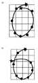
平滑処理部30は、対象物体追跡部20が求めた指先の画素座標データに平滑処理を施す。例えば、ユーザが自由空間中に指先で水平な直線を描くと仮定する。この場合、図2に示すように、ユーザが直線を描いたつもりでも、実際に描かれた軌道は手振れや外乱光または周囲の振動などの影響によって一点斜線で示すような波状の曲線となることが多い。この波形状を直線形状に補正するためにこの平滑処理を行う。[Smoothing processing part]
The smoothing processing unit 30 performs smoothing processing on the pixel coordinate data of the fingertip obtained by the target object tracking unit 20. For example, assume that the user draws a horizontal straight line with a fingertip in free space. In this case, as shown in FIG. 2, even if the user intends to draw a straight line, the actually drawn trajectory will be a wavy curve as shown by a one-point diagonal line due to the influence of hand shake, disturbance light, ambient vibration, etc. There are many. This smoothing process is performed to correct this wave shape to a linear shape.
具体的には、相互に隣接する指先の画素座標のペアの中点を求め、これを平滑処理後の画素座標とする。例えば、図2の「座標n−2」および「座標n−1」と、「座標n−1」および「座標n」のペアは、それぞれ相互に隣接する指先の画素座標である。まず、「座標n−2」と「座標n−1」との間の中点を求め、この中点を平滑処理後の指先の画素座標n−1とする。同様に、「座標n−1」と「座標n」との間の中点を求めて平滑処理後の指先の画素座標nとする。
この平滑処理によって、手振れ等による軌道の誤差を補正することができる。補正後の指先の画素座標は挙動ベクトル特定部40に送られる。
なお、本実施形態における平滑処理はこの手法に限定されるものではない。代替的に最小二乗法などの周知の近似手法を用いてもよい。Specifically, the midpoint of a pair of pixel coordinates of fingertips adjacent to each other is obtained and used as the pixel coordinates after smoothing processing. For example, a pair of “coordinate n−2” and “coordinate n−1” and “coordinate n−1” and “coordinate n” in FIG. 2 are pixel coordinates of fingertips adjacent to each other. First, a midpoint between “coordinate n−2” and “coordinate n−1” is obtained, and this midpoint is set as the pixel coordinate n−1 of the fingertip after the smoothing process. Similarly, the midpoint between “coordinate n−1” and “coordinate n” is obtained and set as the pixel coordinate n of the fingertip after smoothing.
By this smoothing process, an error in the trajectory due to camera shake or the like can be corrected. The corrected pixel coordinates of the fingertip are sent to the behavior vector specifying unit 40.
Note that the smoothing process in the present embodiment is not limited to this method. Alternatively, a well-known approximation method such as a least square method may be used.
[挙動ベクトル特定部]
挙動ベクトル特定部40は、平滑処理後の指先の画素座標のデータを基に、指先の移動方向をベクトル(以下、「挙動ベクトル」と称する)で求める機能を有する。
図3(a)は、指先の軌道の例を示しており、軌動上の点1ないし5は平滑処理後の指先の画素座標である。この画素座標に対してそれぞれの挙動ベクトルを求める。なお、ベクトルは通常大きさと方向の2つの要素を有するが、本実施形態で求める挙動ベクトルは方向の要素のみを有する。挙動ベクトルの求め方は特に限定するものではないが、相互に隣接する画素座標同士を直線で結ぶことで求めてよい。[Behavior vector identification part]
The behavior vector specifying unit 40 has a function of obtaining the moving direction of the fingertip as a vector (hereinafter referred to as “behavior vector”) based on the pixel coordinate data of the fingertip after the smoothing process.
FIG. 3A shows an example of the trajectory of the fingertip, and points 1 to 5 on the trajectory are pixel coordinates of the fingertip after the smoothing process. Each behavior vector is obtained for the pixel coordinates. Note that the vector normally has two elements of magnitude and direction, but the behavior vector obtained in this embodiment has only the direction element. The method of obtaining the behavior vector is not particularly limited, but may be obtained by connecting pixel coordinates adjacent to each other with a straight line.
本実施例では、後段で行う演算処理を簡略化するために、求めた挙動ベクトルを図3(b)に示すような9種類のベクトルパターン、すなわち、右、右下、下、左下、左、左上、上、右上、静止状態の何れかに分類する。具体的には、各画素座標における挙動ベクトルを求め、求めたベクトルに最も類似するベクトルパターンを選択し、そのベクトルパターンを該当の座標での挙動ベクトルとする。なお、本発明の発明者は種々の実験と経験により、ユーザが自由空間に描く直線軌跡は、垂直方向と水平方向は比較的正確であるが、斜め方向は不正確になるという事実を発見した。そこで、本実施形態では、ベクトルパターンの類似範囲を均等ではなく、ベクトルパターン1、3、5、7を±15°の範囲と比較的狭く設定し、ベクトルパターン2、4、6、8を±30°の範囲と広く設定した。これにより、より正確に挙動ベクトルを求めることができる。 In the present embodiment, in order to simplify the arithmetic processing performed in the subsequent stage, the obtained behavior vectors are nine types of vector patterns as shown in FIG. 3B, that is, right, lower right, lower, lower left, left, It is classified into one of upper left, upper, upper right, and stationary state. Specifically, a behavior vector at each pixel coordinate is obtained, a vector pattern most similar to the obtained vector is selected, and the vector pattern is set as a behavior vector at the corresponding coordinate. The inventor of the present invention has found through the various experiments and experiences that the straight line locus drawn by the user in free space is relatively accurate in the vertical and horizontal directions, but inaccurate in the oblique direction. . Therefore, in the present embodiment, the vector pattern similarity range is not uniform, and the
以上の方法で求めた挙動ベクトルを図3(c)に示す。画素座標1ないし5の挙動ベクトルのパターンは、それぞれ1、2、3、2、1となった。このように、各画素座標における挙動ベクトルを9種類のパターンに限定することによって、以降に行う処理を単純化することができる。 The behavior vector obtained by the above method is shown in FIG. The patterns of behavior vectors of pixel coordinates 1 to 5 are 1, 2, 3, 2, 1 respectively. In this way, by limiting the behavior vector at each pixel coordinate to nine types of patterns, the subsequent processing can be simplified.
上述の挙動ベクトルパターンの中の「静止状態」について補足説明する。自由空間中に文字や数字などを描く場合には、必ずその軌道がその終了点で一旦停止する。したがって、隣接する画素座標の間の移動量が一定以下の場合は「静止状態」にあると見なす。なお、「一定量」の範囲は撮像装置のフレームレートやフレーム画像の解像度に依存して決定されるが、例えば、5〜10画素の範囲であってよい。 A supplementary description will be given of the “still state” in the above-described behavior vector pattern. When drawing letters or numbers in free space, the trajectory always stops once at its end point. Therefore, when the amount of movement between adjacent pixel coordinates is below a certain level, it is considered to be in a “still state”. The “fixed amount” range is determined depending on the frame rate of the imaging apparatus and the resolution of the frame image, but may be in the range of 5 to 10 pixels, for example.
また、「静止状態」の発生箇所は上述の終了点だけに限定されるものではない。図4では、指先が矢印に示す軌道を描いた場合における指の位置する画素座標の推移を示している。ここで、軌道の角部付近の箇所である座標4ないし7では、指先が顕著に移動していないことがわかる。このように、軌道の角、すなわち、挙動ベクトルの方向が大きく変わる箇所では被認識物体である指先の移動量が減少する。本実施形態では、座標4ないし7を「静止状態」と特定する。
以上の処理により得られたデータは、1つのフレーム画像に対応する指の挙動ベクトルを1ブロックとして構成した時系列のデータとなる。この挙動ベクトルのデータは特徴点解析部50に送られる。Further, the occurrence location of the “still state” is not limited to the above-described end point. FIG. 4 shows the transition of the pixel coordinates where the finger is positioned when the fingertip draws a trajectory indicated by an arrow. Here, it can be seen that the fingertips are not remarkably moved at the
The data obtained by the above processing is time-series data in which the finger behavior vector corresponding to one frame image is configured as one block. The behavior vector data is sent to the feature point analysis unit 50.
[特徴点解析部]
特徴点解析部50は、挙動ベクトル特定部40が求めたデータ内の「特徴点」を示すデータブロックに着目し、適切な処理を行う機能を有する。なお、本実施形態で「特徴点」とは、隣接し、かつ同一の挙動ベクトルを示す一群のデータブロック、並びに、「静止状態」と特定されたデータブロックである。
詳細は図5を参照して説明する。図5(a)は、ユーザが自由空間中に指先で「L」の文字の軌道を描いたときの指の位置1ないし10とそれぞれの指の位置の挙動ベクトルを示している。ここで指の位置1および2の挙動ベクトルは「パターン3」であり、指の位置3ないし6の挙動ベクトルは「静止状態」であり、指の位置7ないし9の挙動ベクトルは「パターン1」であり、画素座標10は「静止状態」である。実際の挙動ベクトルのデータ構造は、それぞれの指の位置における挙動ベクトルを1つのデータブロックとして、位置1ないし10の順番で並列している。まず、同一の挙動ベクトルを示すデータブロックが隣接する場合には、単一のデータブロックにまとめる。すなわち、図5(b)に示すように指の位置1および2と、3ないし6と、7ないし9とをそれぞれ単一のデータブロックとする。[Feature Point Analysis Section]
The feature point analysis unit 50 has a function of paying attention to a data block indicating a “feature point” in the data obtained by the behavior vector specifying unit 40 and performing an appropriate process. In the present embodiment, “feature points” are a group of data blocks that are adjacent and exhibit the same behavior vector, and data blocks that are identified as “still state”.
Details will be described with reference to FIG. FIG. 5A shows the
次に、「静止状態」を示す指の位置3および10に着目する。上述のように「静止状態」のデータブロックは、ジェスチャーの終了点と角部の何れかに指が位置した状態に該当するため、そのどちらであるかを識別する必要がある。図5(c)は、図5(b)に示した挙動ベクトルのそれぞれの持続時間を示している。ここで、データブロック1で挙動ベクトル「パターン3」が持続した時間を「a」、データブロック3で挙動ベクトル「静止状態」が持続した時間を「b」、データブロック7で挙動ベクトル「パターン1」が持続した時間を「c」、データブロック10で挙動ベクトル「静止状態」が持続した時間を「d」とする。 Next, attention is paid to
各挙動ベクトルの持続時間を求めた後は、「静止状態」のデータブロックにおけるその持続時間と、その1つ前のデータブロックの挙動ベクトルの持続時間とを比較し、「静止状態」の持続時間が1つ前の挙動ベクトルの持続時間よりも短ければ、「静止状態」は軌道の「角部」に該当すると断定する。一方、「静止状態」の持続時間が1つ前の挙動ベクトルの持続時間よりも長ければ、「静止状態」は軌道の「終了点」に該当すると断定する。従って、図5(c)では、画素座標3が軌跡の「角部」に該当し、画素座標10が軌跡の「終了点」に該当する。その結果、ユーザがジェスチャーとして自由空間中に描いた軌道は、図5(d)に示す、挙動ベクトル3および1から構成されるL形の文字であることがわかる。
特徴点解析部50が解析した結果はパターンマッチング部60に送られる。After obtaining the duration of each behavior vector, the duration of the “static state” data block is compared with the duration of the behavior vector of the previous data block, and the duration of “static state” is determined. Is shorter than the duration of the previous behavior vector, it is determined that the “stationary state” corresponds to the “corner” of the orbit. On the other hand, if the duration of the “static state” is longer than the duration of the previous behavior vector, it is determined that the “static state” corresponds to the “end point” of the trajectory. Accordingly, in FIG. 5C, the pixel coordinate 3 corresponds to the “corner portion” of the locus, and the pixel coordinate 10 corresponds to the “end point” of the locus. As a result, it is understood that the trajectory drawn in the free space as a gesture by the user is an L-shaped character composed of the
The result analyzed by the feature point analysis unit 50 is sent to the pattern matching unit 60.
[パターンマッチング部]
パターンマッチング部60は、特徴点解析部50から受け取ったデータを基にユーザの指先によって描かれた軌道、すなわち、指先のジェスチャーを特定する機能を有する。詳細には、予め作成されてデータ格納部90に記録された複数のジェスチャーパターンのデータの中で特徴点解析部50から受け取ったデータと一致するものがあるかどうかを検索する。一致するジェスチャーパターンがある場合にはそのジェスチャーパターンがユーザの行ったジェスチャーであると判断する。
上述のようにジェスチャーには、終了点を有するものと、終了点を有しないものの2通りがある。それぞれの場合について処理内容を説明する。[Pattern matching section]
The pattern matching unit 60 has a function of specifying a trajectory drawn by the user's fingertip based on the data received from the feature point analysis unit 50, that is, a fingertip gesture. Specifically, it is searched whether there is any data that matches the data received from the feature point analysis unit 50 among a plurality of gesture pattern data created in advance and recorded in the
As described above, there are two types of gestures: those having an end point and those having no end point. The processing contents will be described for each case.
1、終了点があるジェスチャーを求める場合
図6(a)に示す軌道に該当するジェスチャーを求める場合を例にして説明する。ユーザが指先で自由空間中に点線で示す文字「U」の軌道を描いたとする。この軌道のデータをジェスチャー認識装置1000のフレーム画像受信部10ないし特徴点解析部50で処理し、その結果得られたデータを表1に示す。この表では画素座標「A」ないし「J」における挙動ベクトルパターンの値がそれぞれ示されている。1. Obtaining a gesture with an end point An example of obtaining a gesture corresponding to the trajectory shown in FIG. It is assumed that the user has drawn the trajectory of the letter “U” indicated by a dotted line in the free space with the fingertip. The trajectory data is processed by the frame

次に、データ格納部90に記録されたジェスチャーパターンの中で、ジェスチャー「U」に該当するパターンを表2にそれぞれ示す。 Next, in the gesture patterns recorded in the
パターンマッチング部60は、特徴点解析部50から受け取ったデータを参照して、最初に終了点を捜索する。表1を参照すると、データ列Iに終了点が存在していることがわかる。そのため、終了点の1つ前のデータ列Hに着目し、最後のデータ列(ブロック)の挙動ベクトルが「パターン8」であるジェスチャーパターンを検索する。次に、最後から2番目の挙動ベクトルが「パターン7」であるジェスチャーパターンを検索する。この検索処理を繰り返し、データ列BないしHの軌道がジェスチャー「U」に該当すると認識する。
以降は、挙動ベクトルデータのデータ列AないしIの内容をクリアし、新たにデータ列Jから同様のマッチング処理を繰り返す。このように、終了点を基準とし、かつデータ列の配列順序に遡ってマッチング処理を行えば、開始点の不定により受ける影響を回避することができる。
認識した結果は、類似パターン識別部70に送られる。The pattern matching unit 60 first searches for the end point with reference to the data received from the feature point analysis unit 50. Referring to Table 1, it can be seen that an end point exists in the data string I. Therefore, paying attention to the data string H immediately before the end point, a gesture pattern in which the behavior vector of the last data string (block) is “
Thereafter, the contents of the data strings A to I of the behavior vector data are cleared, and the same matching process is newly repeated from the data string J. In this way, if the matching process is performed using the end point as a reference and going back to the arrangement order of the data strings, it is possible to avoid the influence caused by the indefinite start point.
The recognized result is sent to the similar pattern identifying unit 70.
2、終了点がないジェスチャーを求める場合
図6(b)に示す軌道からジェスチャーを求める場合を例にして説明する。ユーザが指先で自由空間中に点線で示す右回りの軌道を描いたとする。この軌道のデータをジェスチャー認識装置1000のフレーム画像受信部10ないし特徴点解析部50で処理し、その結果得られたデータを表3に示す。この表には画素座標「A」ないし「K」における挙動ベクトルパターンの値がそれぞれ示されている。2. Obtaining a gesture without an end point An example of obtaining a gesture from the trajectory shown in FIG. 6B will be described. It is assumed that the user draws a clockwise trajectory indicated by a dotted line in free space with the fingertip. The trajectory data is processed by the frame
次に、データ格納部90に記録されたジェスチャーパターンの中で、右回りのジェスチャーに該当するパターンを参考として表4に示す。 Next, among the gesture patterns recorded in the
パターンマッチング部60は、最初に特徴点解析部50から受け取ったデータを参照して、終了点を捜索する。表3を参照すると終了点は存在しないことがわかる。そのため、最後のデータ列Kを基点として、かつ基点を含め1つ遡ったデータ列Kの挙動ベクトル「パターン1」で終わるジェスチャーパターンを捜索する。該当するパターンが存在しない場合は、そこで捜索を終了し、該当ジェスチャーは「なし」となる。該当するパターンが1つ以上存在した場合は、捜索の範囲を、基点からさらに1つ遡ったデータ列Jまでの挙動ベクトル「パターン1およびパターン8」で終わるジェスチャーパターンを捜索する。該当するパターンが1つ以上存在した場合は、さらに1つ前のデータ列までを捜索する。以上の手順を繰り返し、画素座標CないしKの軌跡が「右回り」のジェスチャーに該当すると認識する。
認識した結果は類似パターン識別部70に送られる。The pattern matching unit 60 searches for the end point with reference to the data received from the feature point analysis unit 50 first. Referring to Table 3, it can be seen that there is no end point. For this reason, a gesture pattern ending with the behavior vector “
The recognized result is sent to the similar pattern identifying unit 70.
[類似パターン識別部]
類似パターン識別部70は、パターンマッチング部60が特定したジェスチャーが類似パターン群に含まれる場合のみ該当のデータに対して処理を行う。
類似パターンとは、形状が相互に類似している文字、記号等であり、例えば、数字の「6」と数字の「0」、文字の「U」と「V」などが挙げられる。これらの数字または文字のペアは、共に終了点を有し、かつ形状が類似している。そのため、パターンマッチング部60が行うマッチング処理だけではこれらを混同して誤認識を起こすおそれがある。そこで、ジェスチャー認識装置の認識確度を高めるために類似パターン識別部70を設けている。パターンマッチング部60は、画素座標の挙動ベクトルのパターンのみでジェスチャーを特定していたが、この類似パターン識別部70は、画素座標の相対位置を用いてジェスチャーを特定する。[Similar pattern identification part]
The similar pattern identifying unit 70 processes the corresponding data only when the gesture specified by the pattern matching unit 60 is included in the similar pattern group.
The similar pattern is a character, symbol, or the like that is similar in shape to each other, and includes, for example, the number “6” and the number “0”, the characters “U” and “V”, and the like. These numbers or letter pairs both have end points and are similar in shape. For this reason, only the matching process performed by the pattern matching unit 60 may confuse these and cause erroneous recognition. Therefore, a similar pattern identification unit 70 is provided to increase the recognition accuracy of the gesture recognition device. The pattern matching unit 60 specifies a gesture using only the behavior vector pattern of pixel coordinates, but the similar pattern identification unit 70 specifies a gesture using the relative position of the pixel coordinates.
図7を参照して、類似パターン識別部70が行う処理について説明する。図7(a)はジェスチャーが数字「0」を示すときの挙動パターン群を示し、図7(b)は数字「6」を示すときの挙動パターン群を示している。双方ともに矢印の画素座標が開始点であり、星印の画素座標が終了点である。図7(a)に示す「0」では、終了点の高さは、開始点の位置とほぼ同一となる。一方、図7(b)に示す「6」では、終了点の高さは、開始点と最下位の点とのほぼ中間の位置となる。このように、開始点および終了点を含む、各画素座標位置の相対位置によって類似パターンの識別を行う。なお、各画素座標位置の相対位置に加えて、角の位置などを基に識別を行ってよい。
類似パターン識別部70によって識別を行った結果は、コマンド出力部80に送られる。With reference to FIG. 7, the process which the similar pattern identification part 70 performs is demonstrated. FIG. 7A shows a behavior pattern group when the gesture indicates the number “0”, and FIG. 7B shows a behavior pattern group when the gesture indicates the number “6”. In both cases, the pixel coordinate of the arrow is the start point, and the pixel coordinate of the star is the end point. In “0” shown in FIG. 7A, the height of the end point is almost the same as the position of the start point. On the other hand, in “6” shown in FIG. 7B, the height of the end point is a substantially intermediate position between the start point and the lowest point. In this way, the similar pattern is identified by the relative position of each pixel coordinate position including the start point and the end point. In addition to the relative position of each pixel coordinate position, identification may be performed based on a corner position or the like.
The result of identification by the similar pattern identification unit 70 is sent to the command output unit 80.
[コマンド出力部]
コマンド出力部80はデータ格納部90にアクセスして、パターンマッチング部60または類似パターン識別部70が特定したジェスチャーに対応するコマンドを選択して、そのコマンドを所定のフォーマットで後段の処理装置に出力する機能を有する。コマンドの例としては、特に限定するものではないが「画面を上または下にスクロールする」、「カーソルを所定の方向に移動する」、「所定のプログラムの起動」などが挙げられる。[Command output part]
The command output unit 80 accesses the
[データ格納部]
データ格納部90は、メモリ、ハードディスク、CD、DVDなどで実装される格納手段であり、所定のデータをその内部に記録する機能を有する。記録するデータの例としては、パターンマッチング部60がマッチング処理に用いる「挙動ベクトルのパターンとジェスチャーとの関連データ」、類似パターン識別部が類似パターンのジェスチャーを識別するために用いる「類似パターンの一覧とその識別方法のデータ」、コマンド出力部80がジェスチャーに対応するコマンドを選択するための「ジェスチャーとコマンドの対応データ」などである。[Data storage section]
The
以上、本実施形態に係るジェスチャー認識装置1000の機能要素について説明した。次は、このジェスチャー認識装置1000が行うジェスチャー認識方法について図8ないし図11のフロー図を参照して説明する。 The functional elements of the
[物体のジェスチャー認識方法]
図8のフロー図を参照して説明する。最初に、フレーム画像受信部10が撮像装置からユーザの指先を撮像したフレーム画像をリアルタイムで受け取る(ステップS100)。フレーム画像を受け取ると、対象物体追跡部20がこのフレーム画像における指先の画素座標を検出し、時系列の画素座標データを生成する(ステップS200)。画素座標データを生成すると、平滑処理部30がこのデータに対して平滑処理を施す(ステップS300)。[Object Gesture Recognition Method]
This will be described with reference to the flowchart of FIG. First, the frame
次に、挙動ベクトル特定部40が、各画素座標における挙動ベクトルを求め、図3(b)示すベクトルパターン1ないし9(パターン9は「静止状態」)の何れかに特定し、時系列の挙動ベクトルデータを生成する(ステップS400)。 Next, the behavior vector specifying unit 40 obtains a behavior vector at each pixel coordinate, specifies one of the
特定した挙動ベクトル群に対して特徴点解析部50が処理を行うが(ステップS500)、この処理手順については図9のフロー図を参照して詳細に説明する。
最初に、時系列の挙動ベクトルデータの中に同一の挙動ベクトルを示すデータブロックが連続して存在していないかどうかを調査する(ステップS510)。同一の挙動ベクトルを示す2つ以上のデータブロックが連続して存在していた場合には(ステップS510で「YES」)、それらの画素座標を単一のデータブロックにまとめて(ステップS520)、ステップS530の処理に進む。一方、同一の挙動ベクトルを有する2つ以上のデータブロックが連続して存在していない場合には(ステップS510で「NO」)、そのままステップS530の処理に進む。The feature point analysis unit 50 performs processing on the identified behavior vector group (step S500). This processing procedure will be described in detail with reference to the flowchart of FIG.
First, it is investigated whether or not data blocks indicating the same behavior vector are continuously present in the time-series behavior vector data (step S510). If two or more data blocks indicating the same behavior vector exist continuously (“YES” in step S510), their pixel coordinates are combined into a single data block (step S520), The process proceeds to step S530. On the other hand, if two or more data blocks having the same behavior vector do not exist continuously (“NO” in step S510), the process proceeds to step S530 as it is.
次に、時系列の挙動ベクトルデータの中に「パターン9」、すなわち「静止状態」と特定されたデータブロックが存在するかどうかを調査する(ステップS530)。「静止状態」のデータブロックが存在する場合には(ステップS530で「YES」)、該当の「静止状態」の持続時間T1を求め、さらに、その1つ前の挙動ベクトルの持続時間T2を求め、双方の持続時間T1およびT2を比較する(ステップS540)。 Next, it is investigated whether or not there is a data block identified as “
比較の結果、持続時間T2の方が持続時間T1よりも長い場合には(ステップS550で「YES」)、該当の「静止状態」の画素座標は「角部」に該当すると判断する(S560)。そして、ステップS600の処理に進む。一方、持続時間T2の方が持続時間T1よりも短い場合には(ステップS550で「NO」)、該当の「静止状態」の画素座標は「終了点」に該当すると判断する(S570)。そして、ステップS600の処理に進む。 As a result of the comparison, if the duration T2 is longer than the duration T1 (“YES” in step S550), it is determined that the corresponding “still state” pixel coordinates correspond to “corner” (S560). . Then, the process proceeds to step S600. On the other hand, if the duration T2 is shorter than the duration T1 (“NO” in step S550), it is determined that the corresponding “still state” pixel coordinates correspond to the “end point” (S570). Then, the process proceeds to step S600.
また、挙動ベクトルデータの中に「静止状態」、すなわち「パターン9」と特定されたデータブロックが存在しない場合には(ステップS530で「NO」)、ステップS600の処理にそのまま進む。 If there is no data block identified as “still state”, that is, “
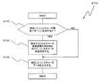
次の図8のステップS600の処理では、パターンマッチング部60がデータ格納部90にアクセスし、このデータ格納部90に記録されたジェスチャーパターンの中で処理対象の挙動ベクトル群と一致するものがあるかどうかを検索する(ステップS600)。この処理を図10のフロー図を参照して詳細に説明する。 In the processing of the next step S600 in FIG. 8, the pattern matching unit 60 accesses the
最初に、処理対象の画素座標群の中に「終了点」と特定されたデータブロックが存在するかどうかを調査する。「終了点」の画素座標が存在する場合には(ステップS601で「YES」)、その「終了点」の一つ前のデータ列を基点として、データ列の配列順序に遡ってデータ格納部90に記録されたジェスチャーパターンとマッチング処理を行う(ステップS602)。マッチング処理の結果、一致するジェスチャーパターンが存在する場合には(ステップS603で「YES」)、その一致したジェスチャーパターンを該当の挙動ベクトル群が示すジェスチャーであると特定する(ステップS604)。最後に「終了点」までのデータブロックの内容をすべてクリアして(ステップS605)、特定したジェスチャーを類似パターン識別部70に出力する(ステップS606)。 First, it is investigated whether or not there is a data block identified as “end point” in the pixel coordinate group to be processed. If the pixel coordinates of the “end point” are present (“YES” in step S601), the
一方、マッチング処理の結果、一致するジェスチャーパターンが存在しない場合には(ステップS603で「NO」)、「終了点」のデータ列より後のデータ列群を新たな処理対象とし(ステップS607)、「終了点」のデータ列までのデータをすべてクリアして(ステップS608)、再度ステップS601からの処理を繰り返す。 On the other hand, if there is no matching gesture pattern as a result of the matching process (“NO” in step S603), a data string group after the “end point” data string is set as a new process target (step S607). All data up to the “end point” data string is cleared (step S608), and the processing from step S601 is repeated again.
また、処理対象の画素座標群の中に「終了点」と特定された画素座標が存在しない場合には(ステップS601で「NO」)、処理対象は終了点のないジェスチャーと判断して、最後のデータ列を基点として、データ列の配列順序に遡ってマッチング処理を行う(ステップS609)。マッチング処理の結果、一致するジェスチャーパターンが存在する場合には(ステップS610で「YES」)、その一致したジェスチャーパターンを該当の挙動ベクトル群のジェスチャーであると特定する(ステップS611)。最後に一時保管可能データ列数を超えるデータをクリアして(ステップS612)、特定したジェスチャーを類似パターン識別部70に出力する(ステップS606)。 If the pixel coordinate specified as “end point” does not exist in the pixel coordinate group to be processed (“NO” in step S601), the processing target is determined to be a gesture without an end point, and the last Using the data string as a base point, matching processing is performed retroactively to the arrangement order of the data string (step S609). If there is a matching gesture pattern as a result of the matching process (“YES” in step S610), the matched gesture pattern is specified as a gesture of the corresponding behavior vector group (step S611). Finally, data exceeding the number of data columns that can be temporarily stored is cleared (step S612), and the identified gesture is output to the similar pattern identifying unit 70 (step S606).
一方、マッチング処理の結果、一致するジェスチャーパターンが存在しない場合には(ステップS610で「NO」)、基点を次のデータ列に変更し、ステップS609以降の処理を繰り返す(ステップS613)。 On the other hand, if there is no matching gesture pattern as a result of the matching process (“NO” in step S610), the base point is changed to the next data string, and the processes after step S609 are repeated (step S613).
次に、図8に示す類似パターン識別部70が行うステップS700の処理は、図11のフロー図を参照して詳細に説明する。まず、パターンマッチング部60が出力したジェスチャーのデータを受け取ると、そのジェスチャーが類似パターンに該当するかどうかを調査する(ステップS710)。類似パターンに該当する場合には(ステップS710で「YES」)、該当するジェスチャーのデータを構成する画素座標のそれぞれの値を比較し、その相対値でジェスチャーを特定する(ステップS720)。なお、必要に応じて角部の座標も用いる。再特定したジェスチャーのデータはコマンド出力部80に出力する(ステップS730)。一方、類似パターンに該当しない場合には(ステップS710で「NO」)、該当するジェスチャーのデータをそのままコマンド出力部80に出力する(ステップS730)。 Next, the process of step S700 performed by the similar pattern identification unit 70 shown in FIG. 8 will be described in detail with reference to the flowchart of FIG. First, when the gesture data output by the pattern matching unit 60 is received, it is investigated whether or not the gesture corresponds to a similar pattern (step S710). If it corresponds to the similar pattern (“YES” in step S710), the values of the pixel coordinates constituting the data of the corresponding gesture are compared, and the gesture is specified by the relative value (step S720). Note that the coordinates of the corners are also used as necessary. The respecified gesture data is output to the command output unit 80 (step S730). On the other hand, when the pattern does not correspond to the similar pattern (“NO” in step S710), the corresponding gesture data is output to the command output unit 80 as it is (step S730).
再び図8を参照すると、類似パターン識別部70が出力したデータは、コマンド出力部80が受け取り、受け取ったジェスチャーのデータに対応するコマンドをデータ格納部90にアクセスして検索する。そして検索したコマンドを必要に応じて後段の処理装置が取り扱う形式に変換した後に当該後段の処理装置に出力する(ステップS800)。
以上が本実施形態に係るジェスチャー認識方法の処理手順である。Referring again to FIG. 8, the data output from the similar pattern identification unit 70 is received by the command output unit 80, and the command corresponding to the received gesture data is accessed and searched. Then, the retrieved command is converted into a format handled by the subsequent processing device as necessary, and then output to the subsequent processing device (step S800).
The above is the processing procedure of the gesture recognition method according to the present embodiment.
本発明の一実施形態に係るジェスチャー認識装置1000が適応される処理装置は特に限定するものではない。例えばパーソナルコンピュータ、携帯端末、ATM、カーナビゲーション、自動販売機、携帯電話、OA機器等の様々な機器に適用してよい。 The processing apparatus to which the
なお、本発明の一実施形態にジェスチャー認識装置1000が有する機能は、特定のハードウェア資源またはソフトウェア処理に限定されないことに留意されたい。すなわち、この機能を実現できる限り、如何なるハードウェア(電子回路等)、ソフトウェア(プログラム)、あるいはそれらの組み合わせ等を用いてよい。 Note that the functions of the
上述した本発明の一実施形態に係るジェスチャー認識方法を、プログラムとして実装する場合には、このプログラムを外部のサーバ等から該方法を実行する情報処理装置にダウンロードするか、あるいはコンピュータ可読媒体の形態で分配されることが好ましい。コンピュータ可読媒体の例としては、CD−ROM、DVD、磁気テープ、フレキシブルディスク、光磁気ディスク、ハードディスク、メモリ媒体などが挙げられる。 When the gesture recognition method according to the embodiment of the present invention described above is implemented as a program, the program is downloaded from an external server or the like to an information processing apparatus that executes the method, or in the form of a computer-readable medium It is preferable that it is distributed by. Examples of the computer readable medium include CD-ROM, DVD, magnetic tape, flexible disk, magneto-optical disk, hard disk, memory medium, and the like.
以上、本発明を図面に示した実施形態を用いて説明したが、これらは例示的なものに過ぎず、本技術分野の当業者ならば、本発明の範囲および趣旨から逸脱しない範囲で多様な変更および変形が可能なことは理解できるであろう。したがって、本発明の範囲は、説明された実施形態によって定められず、特許請求の範囲に記載された技術的趣旨により定められねばならない。 As mentioned above, although this invention was demonstrated using embodiment shown in drawing, these are only an illustration and those skilled in this technical field can variously be within the range which does not deviate from the range and the meaning of this invention. It will be understood that modifications and variations are possible. Accordingly, the scope of the invention should not be determined by the described embodiments, but by the technical spirit described in the claims.
10 フレーム画像受信部
20 対象物体追跡部
30 平滑処理部
40 挙動ベクトル特定部
50 特徴点解析部
60 パターンマッチング部
70 類似パターン識別部
80 コマンド出力部
90 データ格納部
1000 ジェスチャー認識装置DESCRIPTION OF
Claims (13)
Translated fromJapanese前記物体を撮像した動画像を受け取る画像受信手段と、
前記動画像を構成するフレーム画像における前記物体の位置する画素座標を求め、撮像時刻に基づく時系列の画素座標データを生成する物体追跡手段と、
前記求めた画素座標における前記物体の移動方向を上、右上、右、右下、下、左下、左、左上、静止状態の何れかに近似して求め、時系列の移動方向データを生成する移動方向特定部と、
前記移動方向データを特徴点として解析を行う特徴点解析手段と、
前記特徴点解析手段による解析結果に基づいて、予め用意した移動方向の組み合わせからなる複数のジェスチャーパターンの中から前記移動方向データと一致するジェスチャーパターンを検索し、一致したジェスチャーパターンを前記物体が表わしたジェスチャーと判断するパターンマッチング手段と、
を備え、
前記特徴点解析手段は、前記移動方向データにおいて同一の移動方向が隣接する場合には、その隣接する移動方向同士を単一の移動方向にまとめる処理を行い、
前記移動方向が静止状態である場合には、該静止状態の持続時間と、該静止状態の1つ前の移動方向の持続時間とを比較し、該静止状態の持続時間の方が長い場合には該静止状態に対応する画素座標をジェスチャーの終了点と判断し、該静止状態の持続時間の方が短い場合には該静止状態に対応する画素座標をジェスチャーの角部と判断する処理を行うことを特徴とするジェスチャー認識装置。A gesture recognition device for recognizing a predetermined gesture represented by a trajectory of an object moving in free space,
Image receiving means for receiving a moving image obtained by imaging the object;
An object tracking means for obtaining pixel coordinates where the object is located in a frame image constituting the moving image and generating time-series pixel coordinate data based on an imaging time;
Movement that generates time-series movement direction data by obtaining the movement direction of the object at the obtained pixel coordinatesby approximating any of theupper, upper right, right, lower right, lower, lower left, left, upper left, and stationary states. A direction identification part;
A feature point analysis means for analyzing the movement direction data as a feature point;
Based on the analysis result by the feature point analyzing means retrieves a gesture pattern matching the moving direction data from the plurality of gesture pattern consisting of a combination of the movement direction which is prepared in advance, represent the matched gesture pattern the object Pattern matching means to determine that the gesture is
With
When the same movement direction is adjacent in the movement direction data, the feature point analysis means performs a process of grouping the adjacent movement directions into a single movement direction,
When the moving direction is stationary, the duration of the stationary state is compared with the duration of the moving direction immediately before the stationary state, and the duration of the stationary state is longer Judges the pixel coordinates corresponding to the stationary state as the end point of the gesture, and if the duration of the stationary state is shorter, performs the process of determining the pixel coordinates corresponding to the stationary state as the corner of the gesture A gesture recognition device characterized by that.
前記パターンマッチング手段が特定したジェスチャーが前記類似ジェスチャーリストに含まれていた場合には、該ジェスチャーを構成する画素座標の相対位置を基にジェスチャーを再度特定する類似ジェスチャー再特定手段と、
をさらに備えることを特徴とする請求項1ないし3に記載のジェスチャー認識装置。If the similar gesture list that includes a gesture that may cause confusion with other gestures and the gesture specified by the pattern matching means are included in the similar gesture list, the relative coordinates of the pixel coordinates constituting the gesture Similar gesture re-identifying means for re-identifying the gesture based on the position;
The gesture recognition apparatus according to claim 1, further comprising:
前記物体を撮像した動画像を受け取る画像受信段階と、
前記動画像を構成するフレーム画像における前記物体の位置する画素座標を求め、撮像時刻に基づく時系列の画素座標データを生成する物体追跡段階と、
前記求めた画素座標における前記物体の移動方向を上、右上、右、右下、下、左下、左、左上、静止状態の何れかに近似して求め、時系列の移動方向データを生成する移動方向特定段階と、
前記移動方向データを特徴として解析を行う特徴点解析段階と、
前記特徴点解析段階による解析結果に基づいて、予め用意した移動方向の組み合わせからなる複数のジェスチャーパターンの中から前記移動方向データと一致するジェスチャーパターンを検索し、一致したジェスチャーパターンを前記物体が表わしたジェスチャーと判断するパターンマッチング段階と、
を含み、
前記特徴点解析段階では、前記移動方向データにおいて同一の移動方向が隣接する場合には、その隣接する移動方向同士を単一の移動方向にまとめる処理を行い、
前記移動方向が静止状態である場合には、該静止状態の持続時間と、該静止状態の1つ前の移動方向の持続時間とを比較し、該静止状態の持続時間の方が長い場合には該静止状態に対応する画素座標をジェスチャーの終了点と判断し、該静止状態の持続時間の方が短い場合には該静止状態に対応する画素座標をジェスチャーの角部と判断する処理を行うことを特徴とするジェスチャー認識方法。A gesture recognition method for recognizing a predetermined gesture represented by a trajectory of an object moving in free space,
An image receiving stage for receiving a moving image obtained by imaging the object;
An object tracking step of obtaining pixel coordinates where the object is located in a frame image constituting the moving image and generating time-series pixel coordinate data based on an imaging time;
Movement that generates time-series movement direction data by obtaining the movement direction of the object at the obtained pixel coordinatesby approximating any of theupper, upper right, right, lower right, lower, lower left, left, upper left, and stationary states. A direction identification stage;
A feature point analysis stage for analyzing the movement direction data as a feature;
Based on the analysis result of the feature point analysis stage, a gesture pattern that matches the movement direction data is searched from a plurality of gesture patterns that are combinations of movement directions prepared in advance, and the object represents the matching gesture pattern. A pattern matching stage to determine that the gesture is
Including
In the feature point analysis stage, when the same movement direction is adjacent in the movement direction data, the adjacent movement directions are combined into a single movement direction,
When the moving direction is stationary, the duration of the stationary state is compared with the duration of the moving direction immediately before the stationary state, and the duration of the stationary state is longer Judges the pixel coordinates corresponding to the stationary state as the end point of the gesture, and if the duration of the stationary state is shorter, performs the process of determining the pixel coordinates corresponding to the stationary state as the corner of the gesture A gesture recognition method characterized by that.
前記類似判断段階で該ジェスチャーが他のジェスチャーと混同を生ずるおそれのあると判断された場合には、該ジェスチャーを構成する画素座標の相対位置を基にジェスチャーを再度特定する類似ジェスチャー再特定段階と、
をさらに含むことを特徴とする請求項6ないし8の何れか一項に記載のジェスチャー認識方法。A similarity determination step of determining whether the gesture determined in the pattern matching step is a gesture that may cause confusion with other gestures;
A similar gesture respecifying step of respecifying a gesture based on a relative position of pixel coordinates constituting the gesture when it is determined in the similarity determination step that the gesture may be confused with another gesture; ,
The gesture recognition method according to claim 6, further comprising:
Priority Applications (1)
| Application Number | Priority Date | Filing Date | Title |
|---|---|---|---|
| JP2010273457AJP5604279B2 (en) | 2010-12-08 | 2010-12-08 | Gesture recognition apparatus, method, program, and computer-readable medium storing the program |
Applications Claiming Priority (1)
| Application Number | Priority Date | Filing Date | Title |
|---|---|---|---|
| JP2010273457AJP5604279B2 (en) | 2010-12-08 | 2010-12-08 | Gesture recognition apparatus, method, program, and computer-readable medium storing the program |
Publications (2)
| Publication Number | Publication Date |
|---|---|
| JP2012123608A JP2012123608A (en) | 2012-06-28 |
| JP5604279B2true JP5604279B2 (en) | 2014-10-08 |
Family
ID=46504982
Family Applications (1)
| Application Number | Title | Priority Date | Filing Date |
|---|---|---|---|
| JP2010273457AExpired - Fee RelatedJP5604279B2 (en) | 2010-12-08 | 2010-12-08 | Gesture recognition apparatus, method, program, and computer-readable medium storing the program |
Country Status (1)
| Country | Link |
|---|---|
| JP (1) | JP5604279B2 (en) |
Families Citing this family (17)
| Publication number | Priority date | Publication date | Assignee | Title |
|---|---|---|---|---|
| JP5565886B2 (en)* | 2012-08-17 | 2014-08-06 | Necシステムテクノロジー株式会社 | Input device, input method, and program |
| JP5897725B2 (en)* | 2012-10-03 | 2016-03-30 | 楽天株式会社 | User interface device, user interface method, program, and computer-readable information storage medium |
| JP6103875B2 (en)* | 2012-10-16 | 2017-03-29 | キヤノン株式会社 | Hand gesture recognition device and control method thereof |
| JP2014106836A (en)* | 2012-11-29 | 2014-06-09 | Pentel Corp | Coordinate input system |
| EP2908218B1 (en) | 2014-02-14 | 2018-03-14 | Omron Corporation | Gesture recognition apparatus and control method of gesture recognition apparatus |
| JP6349800B2 (en) | 2014-03-12 | 2018-07-04 | オムロン株式会社 | Gesture recognition device and method for controlling gesture recognition device |
| JP6322029B2 (en)* | 2014-03-31 | 2018-05-09 | 株式会社メガチップス | Gesture detection device, operation method of gesture detection device, and control program |
| JP6417794B2 (en)* | 2014-08-29 | 2018-11-07 | オムロンヘルスケア株式会社 | Operation information measuring device, function control method, and program |
| KR102347248B1 (en) | 2014-11-26 | 2022-01-04 | 삼성전자주식회사 | Method and apparatus for recognizing touch gesture |
| CN107533363B (en)* | 2015-04-17 | 2020-06-30 | 三菱电机株式会社 | Gesture recognition device, gesture recognition method, and information processing device |
| JP6481513B2 (en)* | 2015-05-28 | 2019-03-13 | アイシン精機株式会社 | Operating device |
| CN107787497B (en)* | 2015-06-10 | 2021-06-22 | 维塔驰有限公司 | Method and apparatus for detecting gestures in a user-based spatial coordinate system |
| JP2019160034A (en)* | 2018-03-15 | 2019-09-19 | 株式会社ユニオンソフトウェアマネイジメント | Correction system of operation recognition image data |
| JP6623366B1 (en) | 2019-03-27 | 2019-12-25 | 株式会社MARUI−PlugIn | Route recognition method, route recognition device, route recognition program, and route recognition program recording medium |
| CN113494802B (en)* | 2020-05-28 | 2023-03-10 | 海信集团有限公司 | Intelligent refrigerator control method and intelligent refrigerator |
| CN116193243B (en) | 2021-11-25 | 2024-03-22 | 荣耀终端有限公司 | Photography methods and electronic equipment |
| CN116524383A (en)* | 2022-01-20 | 2023-08-01 | 北京字跳网络技术有限公司 | Handle positioning method, device, wearable device, storage medium and program product |
Family Cites Families (12)
| Publication number | Priority date | Publication date | Assignee | Title |
|---|---|---|---|---|
| US9292111B2 (en)* | 1998-01-26 | 2016-03-22 | Apple Inc. | Gesturing with a multipoint sensing device |
| JP2003173239A (en)* | 2001-12-06 | 2003-06-20 | Matsushita Electric Ind Co Ltd | Portable information terminal device and screen display control method |
| JP4153818B2 (en)* | 2003-03-31 | 2008-09-24 | 本田技研工業株式会社 | Gesture recognition device, gesture recognition method, and gesture recognition program |
| JP4237596B2 (en)* | 2003-09-25 | 2009-03-11 | アルプス電気株式会社 | Input device |
| JP4287250B2 (en)* | 2003-11-17 | 2009-07-01 | 株式会社東芝 | Gesture processing device and gesture processing method |
| JP4169130B2 (en)* | 2004-12-27 | 2008-10-22 | サンアロー株式会社 | Method for determining operation direction of operation keys in direction detection switch |
| JP4684745B2 (en)* | 2005-05-27 | 2011-05-18 | 三菱電機株式会社 | User interface device and user interface method |
| JP4613142B2 (en)* | 2006-03-31 | 2011-01-12 | 日本システムウエア株式会社 | Gesture recognition apparatus, online operation system using the same, gesture recognition method, and computer-readable medium |
| JP4711885B2 (en)* | 2006-05-25 | 2011-06-29 | 三菱電機株式会社 | Remote control device and method |
| JP2010015238A (en)* | 2008-07-01 | 2010-01-21 | Sony Corp | Information processor and display method for auxiliary information |
| JP5197338B2 (en)* | 2008-12-08 | 2013-05-15 | キヤノン株式会社 | Information processing apparatus and information processing method |
| JP5381569B2 (en)* | 2009-09-29 | 2014-01-08 | 富士通株式会社 | Gesture recognition device, gesture recognition method, and gesture recognition program |
- 2010
- 2010-12-08JPJP2010273457Apatent/JP5604279B2/ennot_activeExpired - Fee Related
Also Published As
| Publication number | Publication date |
|---|---|
| JP2012123608A (en) | 2012-06-28 |
Similar Documents
| Publication | Publication Date | Title |
|---|---|---|
| JP5604279B2 (en) | Gesture recognition apparatus, method, program, and computer-readable medium storing the program | |
| US9747018B2 (en) | Apparatus and method for controlling object | |
| US5389745A (en) | Handwriting input apparatus for inputting handwritten data from unspecified direction | |
| KR101514169B1 (en) | Information processing device, information processing method, and recording medium | |
| US20090090567A1 (en) | Gesture determination apparatus and method | |
| WO2011142317A1 (en) | Gesture recognition device, method, program, and computer-readable medium upon which program is stored | |
| WO2014045953A1 (en) | Information processing device and method, and program | |
| US9378427B2 (en) | Displaying handwritten strokes on a device according to a determined stroke direction matching the present direction of inclination of the device | |
| US20150242114A1 (en) | Electronic device, method and computer program product | |
| KR20160005656A (en) | Method of performing a touch action in a touch sensitive device | |
| JP5565320B2 (en) | Information processing apparatus and information processing program | |
| CN103390013A (en) | Electronic device and handwritten document processing method | |
| EP2626813A2 (en) | Apparatus and method for guiding handwriting input for handwriting recognition | |
| WO2021053130A1 (en) | A method and correspond device for selecting graphical objects | |
| US20140270529A1 (en) | Electronic device, method, and storage medium | |
| US9304679B2 (en) | Electronic device and handwritten document display method | |
| WO2019134606A1 (en) | Terminal control method, device, storage medium, and electronic apparatus | |
| US20150293690A1 (en) | Method for user interface display and electronic device using the same | |
| US20100245266A1 (en) | Handwriting processing apparatus, computer program product, and method | |
| JP6599504B2 (en) | Touch error calibration method and system | |
| US9256360B2 (en) | Single touch process to achieve dual touch user interface | |
| JP2014082605A (en) | Information processing apparatus, and method of controlling and program for the same | |
| JP5735126B2 (en) | System and handwriting search method | |
| JP6223687B2 (en) | Electronic device and handwritten document search method | |
| JP2013077180A (en) | Recognition device and method for controlling the same |
Legal Events
| Date | Code | Title | Description |
|---|---|---|---|
| A621 | Written request for application examination | Free format text:JAPANESE INTERMEDIATE CODE: A621 Effective date:20130613 | |
| A977 | Report on retrieval | Free format text:JAPANESE INTERMEDIATE CODE: A971007 Effective date:20131218 | |
| A131 | Notification of reasons for refusal | Free format text:JAPANESE INTERMEDIATE CODE: A131 Effective date:20131224 | |
| A521 | Request for written amendment filed | Free format text:JAPANESE INTERMEDIATE CODE: A523 Effective date:20140213 | |
| TRDD | Decision of grant or rejection written | ||
| A01 | Written decision to grant a patent or to grant a registration (utility model) | Free format text:JAPANESE INTERMEDIATE CODE: A01 Effective date:20140728 | |
| A61 | First payment of annual fees (during grant procedure) | Free format text:JAPANESE INTERMEDIATE CODE: A61 Effective date:20140825 | |
| R150 | Certificate of patent or registration of utility model | Ref document number:5604279 Country of ref document:JP Free format text:JAPANESE INTERMEDIATE CODE: R150 | |
| R250 | Receipt of annual fees | Free format text:JAPANESE INTERMEDIATE CODE: R250 | |
| R250 | Receipt of annual fees | Free format text:JAPANESE INTERMEDIATE CODE: R250 | |
| LAPS | Cancellation because of no payment of annual fees |