JP5604144B2 - Sample component analyzer - Google Patents
Sample component analyzerDownload PDFInfo
- Publication number
- JP5604144B2 JP5604144B2JP2010066028AJP2010066028AJP5604144B2JP 5604144 B2JP5604144 B2JP 5604144B2JP 2010066028 AJP2010066028 AJP 2010066028AJP 2010066028 AJP2010066028 AJP 2010066028AJP 5604144 B2JP5604144 B2JP 5604144B2
- Authority
- JP
- Japan
- Prior art keywords
- sample
- syringe
- suction
- suction nozzle
- time
- Prior art date
- Legal status (The legal status is an assumption and is not a legal conclusion. Google has not performed a legal analysis and makes no representation as to the accuracy of the status listed.)
- Active
Links
Images


Landscapes
- Sampling And Sample Adjustment (AREA)
Description
Translated fromJapanese本発明は、シリンジに採取した検体を、シリンジの内部から装置に取り込んで、取り込んだ検体の成分を分析する検体成分分析装置に関する。 The present invention relates to a sample component analyzer that takes a sample collected in a syringe into the apparatus from the inside of the syringe and analyzes the components of the taken sample.
従来から、シリンジに検体(典型的には血液)を採取し、該シリンジに採取した検体を装置内に取り込んで、取り込んだ検体の成分を分析する検体成分分析装置がある。
このような検体成分分析装置において、検体を装置内に取り込む方法としては、シリンジから装置内に検体を押し込む方法と、シリンジ内の検体を装置側から吸引する方法とがある。
前者の方法を採用する装置は、シリンジから押し込まれた検体が流れる流路を途中で分岐し、一方の分岐路に成分分析用のセンサ部を設け、他方の分岐路を直接排液部に接続し、シリンジから検体を押し込み過ぎた時に余分な検体が排液部に繋がる分岐路に流れるようにして、シリンジからの押し込み量の変動に影響されることなく、センサ部に一定量の検体が導かれるように構成されている。
しかし、このシリンジから装置内に検体を押し込む方法の場合、押し込み操作を人間が行うことになるため、例えば、操作者が検体を過度に急速に押し込んだ場合には流路が詰まってしまう可能性があるという問題がある。流路が詰まった状態でさらに無理やり検体を押し込んでしまうと、押し込まれた力の逃げ場がなくなり検体が飛び散って操作者が検体を浴びてしまう可能性があるので大きな問題である。
これに対して、シリンジ内の検体を装置側から吸引する方法の場合には、吸引力及び吸引量を装置側でコントロールできるので上記したような問題は生じない。2. Description of the Related Art Conventionally, there is a sample component analyzer that collects a sample (typically blood) with a syringe, takes the sample collected with the syringe into the apparatus, and analyzes the components of the taken sample.
In such a sample component analyzer, methods for taking a sample into the device include a method for pushing the sample from the syringe into the device and a method for sucking the sample in the syringe from the device side.
A device that employs the former method branches the flow path through which the sample pushed from the syringe flows, provides a sensor unit for component analysis on one branch path, and connects the other branch path directly to the drainage section. However, when the sample is pushed too far from the syringe, the excess sample flows to the branch path connected to the drainage unit, and a certain amount of sample is introduced to the sensor unit without being affected by fluctuations in the push amount from the syringe. It is configured to be.
However, in the case of the method of pushing the specimen from the syringe into the apparatus, the pushing operation is performed by a human, and therefore, for example, if the operator pushes the specimen too rapidly, the flow path may be clogged. There is a problem that there is. If the sample is forcibly pushed in while the flow path is clogged, there is no possibility of the force to be pushed away and the sample may scatter and the operator may be exposed to the sample.
On the other hand, in the case of the method of sucking the sample in the syringe from the apparatus side, the above-mentioned problems do not occur because the suction force and the suction amount can be controlled on the apparatus side.
しかし、シリンジ内の検体を装置側から吸引する場合、シリンジ内にノズルを侵入させて検体の吸引を行う必要があるため、時間がかかるという問題がある。
即ち、シリンジから装置内に検体を押し込む方法の場合には、単に操作者がシリンジを装置に接続して押し込むだけでよいが、シリンジ内の検体を装置側から吸引する場合には、シリンジが装置にセットされているか否かを確認し、シリンジが装置にセットされていると判断したら、ノズルを動かしてシリンジ内に侵入させ、その後、ノズルによる検体の吸引を行う必要があるため、これらの確認処理及び移動処理に要する時間が余分にかかる。また、検体、特に、血液は、検体毎に粘度が異なるため、吸引速度が高いと、同じ吸引力で同じ時間吸引をしても、粘度が低い検体に比べて粘度が高い検体は吸引量が少なくなるという問題がある。吸引量に変動があるとセンサ部に導かれる検体の量も変動してしまうため、安定した分析結果を得ることができないので問題である。このため、従来の分析装置では、粘度の違いの影響を受けない吸引速度、即ち、比較的ゆっくりとした吸引速度で検体の吸引を行っている。しかし、このように吸引速度に制限があると、シリンジから装置内への検体の取り込み時間を短縮することができないため、結果として分析速度を上げることができないという問題がある。
検体の成分分析は時間を短縮することが望まれる場面が多く、特に、血液ガス分析の測定が必要な場合には、分単位のオーダーで治療のための処置が必要で、治療指針を得るために行なわれる検査の時間を短縮することが求められる場面もあるので、シリンジ内の検体を装置側から吸引する方法において吸引時間を短縮することは非常に重要な課題である。
本発明は、上記した従来の問題点を解決し、シリンジから装置内への検体の取り込み時間を十分に短縮することができる検体成分分析装置を提供することを目的としている。However, when the sample in the syringe is aspirated from the apparatus side, there is a problem that it takes time because the sample needs to be aspirated by inserting a nozzle into the syringe.
That is, in the case of the method of pushing the sample from the syringe into the apparatus, the operator may simply connect and push the syringe into the apparatus. However, when the sample in the syringe is aspirated from the apparatus side, the syringe is the apparatus. If it is determined that the syringe is set in the device, it is necessary to move the nozzle to enter the syringe and then aspirate the sample with the nozzle. Extra time is required for processing and moving processing. In addition, since the viscosity of specimens, particularly blood, differs from specimen to specimen, if the suction speed is high, even if suction is performed for the same time with the same suction force, the specimen with a higher viscosity has a lower suction volume than the specimen with a lower viscosity. There is a problem of fewer. If the amount of aspiration varies, the amount of the sample guided to the sensor unit also varies, which is a problem because a stable analysis result cannot be obtained. For this reason, in the conventional analyzer, the sample is aspirated at a suction speed that is not affected by the difference in viscosity, that is, at a relatively slow suction speed. However, if the suction speed is limited in this way, the time for taking the sample from the syringe into the apparatus cannot be shortened, resulting in a problem that the analysis speed cannot be increased.
In many cases, it is desirable to shorten the time of component analysis of specimens, especially when blood gas analysis measurement is required, treatment for treatment is required on the order of minutes, in order to obtain treatment guidelines. In some cases, it is required to reduce the time for the inspection performed in this way. Therefore, it is very important to reduce the aspiration time in the method for aspirating the specimen in the syringe from the apparatus side.
An object of the present invention is to solve the above-mentioned conventional problems and to provide a sample component analyzer that can sufficiently shorten the time for taking a sample from a syringe into the device.
上記した目的を達成するために、本発明に係る検体成分分析装置は、検体を採取したシリンジを装着可能なシリンジ装着部と、前記シリンジ装着部に装着されたシリンジの内部に侵入して、シリンジの内部の検体を吸引する吸引ノズルと、前記吸引ノズルに接続された吸引ポンプと、前記吸引ノズルで吸引した検体の成分を分析するためのセンサと少なくとも前記吸引ポンプの動作を制御する制御装置とを備えた検体成分分析装置において、吸引ノズル内の検体の流速を測定する手段を設け、前記制御装置に予め標準的な粘度の検体に合わせた基本吸引時間を記憶させておき、前記測定手段により測定した吸引ノズル内での実際の検体の流速が、予め決めておいた基準値より早ければ基本吸引時間を短縮するよう補正し、前記流速が予め決めておいた基準値より遅ければ基本吸引時間を延長するように補正するよう前記前記制御装置を構成したことを特徴とする。
前記標準的な粘度の検体に合わせた基本吸引時間は、具体的には、100μLの検体を内径0.7mmの流路で吸引する場合に2秒であり得る。In order to achieve the above-described object, a sample component analyzing apparatus according to the present invention includes a syringe mounting portion to which a syringe from which a sample is collected can be mounted, and a syringe inserted into the syringe mounted on the syringe mounting portion. An aspiration nozzle for aspirating the specimen inside, a suction pump connected to the aspiration nozzle, a sensor for analyzing the component of the specimen aspirated by the aspiration nozzle, and a control device for controlling at least the operation of the aspiration pump; Provided with means for measuring the flow rate of the sample in the suction nozzle,and storing the basic suction time according to the sample of standard viscosity in advance in the control device, If the actual flow velocity of the sample in the measured suction nozzle is faster than a predetermined reference value, the basic aspiration time is corrected to be shortened, and the flow velocity is determined in advance. Characterized inthat constitute the said control device to correct to extend late as basic suction time than Oita reference value.
Specifically, the basic aspiration time according to the standard viscosity specimen may be 2 seconds when a 100 μL specimen is aspirated through a flow path having an inner diameter of 0.7 mm.
本発明に係る検体成分分析装置は、検体を採取したシリンジを装着可能なシリンジ装着部と、前記シリンジ装着部に装着されたシリンジの内部に侵入して、シリンジの内部の検体を吸引する吸引ノズルと、前記吸引ノズルに接続された吸引ポンプと、前記吸引ノズルで吸引した検体の成分を分析するためのセンサと少なくとも前記吸引ポンプの動作を制御する制御装置とを備えた検体成分分析装置において、吸引ノズル内の検体の流速を測定する手段を設け、前記制御装置に予め標準的な粘度の検体に合わせた基本吸引時間を記憶させておき、前記測定手段により測定した吸引ノズル内での実際の検体の流速が、予め決めておいた基準値より早ければ基本吸引時間を短縮するよう補正し、前記流速が予め決めておいた基準値より遅ければ基本吸引時間を延長するように補正するよう前記前記制御装置を構成しているので、流速が遅い検体の場合には検体を吸引する時間を長くし、流速が速い検体の場合には検体を吸引する時間を短くすることによって常に同じ量の検体を装置内に取り込むことが可能になり。このように流速の差、即ち、粘度の違いに応じて吸引時間を調整することができるように構成することで、吸引速度を上げることが可能になり、結果として、装置内への検体の取り込み時間を短縮することが可能になるという効果を奏する。A sample component analyzer according to the present invention includes a syringe mounting portion on which a syringe from which a sample is collected can be mounted, and a suction nozzle that enters the inside of the syringe mounted on the syringe mounting portion and sucks the sample inside the syringe A specimen component analyzer comprising: a suction pump connected to the suction nozzle; a sensor for analyzing a component of the specimen sucked by the suction nozzle; and a control device for controlling at least the operation of the suction pump; A means for measuring the flow rate of the sample in the suction nozzle is provided,and the basic suction time according to the standard viscosity sample is stored in the control device in advance, and the actual suction nozzle measured by the measurement means is measured. If the flow rate of the specimen is earlier than a predetermined reference value, the basic aspiration time is corrected to be shortened. If the flow rate is slower than the predetermined reference value, the basic flow rate is corrected. Sinceconstitutes the said control device to correct to extend between the time of drawing, to lengthen the time for sucking the sample in the case of the flow rate is low analyte, in the case of the flow velocity is fast sample aspirating the specimen By shortening the time, the same amount of specimen can always be taken into the device. By configuring the suction time to be adjusted according to the difference in flow rate, that is, the difference in viscosity in this way, the suction speed can be increased, and as a result, the sample is taken into the apparatus. There is an effect that the time can be shortened.
以下、添付図面を参照して本発明に係る検体成分分析装置の実施の形態について説明していく。 Embodiments of a sample component analyzer according to the present invention will be described below with reference to the accompanying drawings.
図1は、本発明に係る検体成分分析装置1の一実施例の斜視図を、図2は、検体成分分析装置1におけるシリンジ装着部にシリンジSを装着した状態を示す拡大図を各々示している。
図中符号2は検体成分分析装置1のケーシングを示しており、符号3は操作パネルとしても機能するモニタを示しており、符号4は分析結果を印字するためのプリンタを示している。
ケーシング2の前面には較正液タンク5、洗浄液タンク7及び廃液タンク6が着脱可能に装着されている。
ケーシング2の上面前方には、シリンジSを装着するためのシリンジ装着部8が設けられている。シリンジ装着部8には、シリンジSの装着の有無を検知するシリンジ検知センサ8aが設けられている(図3参照)。
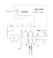
また、図3に示すように、ケーシング2の内部には、
装着部8に装着されたシリンジSの内部に出し入れすることができるように構成された吸引ノズル10と、
吸引ノズル10を動かすための作動部11と、
吸引ノズル10に接続された吸引回路12と、
吸引回路12を通して吸引ノズル10に吸引力を生じさせるポンプ13と、
吸引回路12におけるポンプ13の上流に配置されたフローセンサ14と、
吸引回路12におけるポンプ13とフローセンサ14との間に配置された分析用センサ部15と、
上記各部を制御する制御装置16と
が設けられている。
また、図1及び図3において符号20は、吸引ノズル10がシリンジSに出し入れ可能に動作され得るように吸引ノズル10を収容する吸引ノズル収容部を示している。
図2に示すように、吸引ノズル10は、少なくともシリンジSの内部に侵入可能な直径を有する先端部10aと、先端部10aに繋がり、少なくとも先端部10aより直径が小さい胴体部10bとを有する。
前記吸引ノズル収容部20には、吸引ノズル10の先端部10aによって閉弁可能な第一弁21及び第二弁22が、吸引ノズル10の移動方向に沿って間隔を開けて配置されている。吸引ノズル収容部20における前記二つの弁21及び22の間には、洗浄液導入口23及び廃液口24が設けられている。具体的な動作については後述するが、必要に応じて、不図示のポンプ(又はポンプ13)によって前記洗浄液タンク7から前記洗浄液導入口23を介して洗浄液が吸引ノズル収容部20の内部に供給され、ポンプ13を介して吸引ノズル内に洗浄液が吸引され、フローセンサー14、分析用センサ部15を通って、廃液タンク6に廃液される。また、不図示のポンプ(又はポンプ13)によって前記廃液口24を介して吸引ノズルへは吸引されなかった洗浄液を前記廃液タンク6に吸引する。
制御装置16は、シリンジ検知センサ8a及びフローセンサ14からの信号を入力して、これらの信号に基づいて、作動部11及びポンプ13の動作を制御する。
また、制御装置16は、分析用センサ部15からの検知信号に基づいて成分分析を行い、その分析結果をモニタ3及びプリンタ4に出力する。分析用センサ部15からの検知信号に基づく成分分析処理については、公知の成分分析装置と同様の処理であるので、この明細書では詳細な説明は省略する。FIG. 1 is a perspective view of an embodiment of a sample component analyzing apparatus 1 according to the present invention, and FIG. 2 is an enlarged view showing a state where a syringe S is mounted on a syringe mounting portion of the sample component analyzing apparatus 1. Yes.
In the figure,
A calibration
A
Moreover, as shown in FIG.
A
An
A
A
A
An
And a control device 16 for controlling the above-described units.
Moreover, in FIG.1 and FIG.3, the code |
As shown in FIG. 2, the
A
The control device 16 inputs signals from the
Further, the control device 16 performs component analysis based on the detection signal from the
次に、上記したように構成された成分分析装置1における検体吸引機能について、図3及び図4を参照しながら説明する。
始めに、使用者がシリンジSをシリンジ装着部8に装着する(図4(a))。
使用者が、モニタ3の測定ボタンを押す。
シリンジ検知センサ8aがシリンジSが装着されていることを確認すると制御装置16は、作動部11を動作させて吸引ノズル10を前進させる。
吸引ノズル10の先端部10aがシリンジSの内部に浸入すると(図4(b))、制御装置16はポンプ13を作動して、所定の吸引力でシリンジS内の検体の吸引を開始する。
吸引開始後、フローセンサ14によって検体が検知されると、制御装置16は、吸引開始時間からフローセンサ14による検体の検知までの検体到達時間を算出し、算出した検体到達時間に基づいて、予め決めておいた基本吸引時間の補正値を算出する。そして、制御装置16は、補正した吸引時間に基づいてポンプ13を制御する。
具体的には、実際の検体到達時間が予め決めておいた検体到達時間より短ければ基本吸引時間を短縮するように補正し、逆に実際の検体到達時間が予め決めておいた検体到達時間より長ければ基本吸引時間を延長するように補正する。
これにより、検体の粘度に関係なく、予め決めておいた一定の吸引力(吸引速度)で常に一定量の検体を分析用センサ部15まで引き込むことが可能になる。
また、このように、検体到達時間に基づいて吸引時間を補正するように構成することにより、吸引力は、標準的な粘度の検体に合わせて決めることができる。具体的には、吸引時間を制御しない従来の検体成分分析装置では、粘度の高さに関係なく、一定量の検体を分析用センサ部15まで引き込むために、吸引速度は粘度が高い検体に合わせて比較的遅い速度に設定されている。具体的には、分析用センサ部に検体が満たされて、測定するに十分な検体量である100μL(測定項目数によって異なる)を流路内径0.7mmで吸引するのに約7秒の速さにする必要がある。流路内径を太くすると吸引速度を高くできるが、検体量が多くなり、吸引量を一定にすることが困難になる。このため、粘度が低い検体でも、ゆっくり吸引されることになるため全体の処理時間が長くなる。
これに対して、本発明における検体成分分析装置は、検体到達時間に基づいて吸引時間を補正するため、吸引速度は標準的な粘度の検体に合わせることが可能になり、従来の検体成分分析装置よりも速い速度に設定されている。具体的には、分析用センサ部に検体が満たされて、測定するに十分な検体量である100μL(測定項目数によって異なる)を流路内径0.7mmで吸引するのに、標準的な粘度の検体では約2秒の速さで吸引することができる。このため、検体の吸引に必要な時間が全体として短縮され、全体の処理時間を短くすることが可能になる。
ポンプ13の動作終了後(即ち、検体の吸引終了後)、制御装置16は、分析用センサ部15による検知結果に基づいて成分分析を開始する。
制御装置16は、同時に(又は、分析終了後に)、作動部11を動かして吸引ノズル10を後退させてシリンジSから引き出し、吸引ノズル10は、その先端部10aが、第一弁21及び第二弁22を閉弁する位置まで後退される(図4(c))。これにより、吸引ノズル収容部20内における第一弁21と第二弁22との間に密閉された洗浄空間20aが形成される。
制御装置16は、分析用センサ部15による分析終了後、不図示のポンプ(又はポンプ13)を動作させて、洗浄液導入口23を介して洗浄液タンク7から洗浄空間20a内に洗浄液を供給する。
制御装置16は、洗浄空間20a内に洗浄液が供給された後、ポンプ13を動作させて、吸引ノズル10で洗浄液を吸い込む。吸引ノズル10から吸引された洗浄液は、吸引回路12を通って廃液タンク6に導かれる。これにより、吸引ノズル10及び吸引回路12中の検体は洗浄液によって洗浄される。
制御装置16は、吸引ノズル10及び吸引回路12内の検体及び洗浄液を全て廃液タンク6に排出させた後、不図示のポンプ(又はポンプ13)を動作させて、洗浄空間20aに残っている洗浄液を廃液口24を介して吸引して、廃液タンク6に排水する。
全ての処理が終了したら、次にシリンジSが装着されるまで待機する。Next, the specimen aspirating function in the component analyzer 1 configured as described above will be described with reference to FIGS.
First, the user mounts the syringe S on the syringe mounting portion 8 (FIG. 4A).
The user presses the measurement button on the
When the
When the
When a sample is detected by the
Specifically, if the actual specimen arrival time is shorter than the predetermined specimen arrival time, the basic aspiration time is corrected to be shortened, and conversely, the actual specimen arrival time is determined from the predetermined specimen arrival time. If it is longer, it is corrected to extend the basic suction time.
As a result, regardless of the viscosity of the sample, it is possible to always draw a certain amount of sample to the
Further, as described above, by configuring the aspiration time to be corrected based on the specimen arrival time, the aspiration force can be determined according to a standard viscosity specimen. Specifically, in the conventional specimen component analyzer that does not control the suction time, the suction speed is set to match the specimen with high viscosity in order to draw a certain amount of specimen to the
On the other hand, the sample component analyzer of the present invention corrects the suction time based on the sample arrival time, so the suction speed can be adjusted to a standard viscosity sample. Is set to a faster speed. Specifically, when the sample is filled in the analytical sensor unit, 100 μL (which depends on the number of measurement items), which is a sufficient amount of sample to be measured, is aspirated at 0.7 mm in the inner diameter of the flow path. The sample can be aspirated at a rate of about 2 seconds. For this reason, the time required for aspirating the specimen is shortened as a whole, and the entire processing time can be shortened.
After the operation of the
At the same time (or after the end of the analysis), the control device 16 moves the operating
After the analysis by the
After the cleaning liquid is supplied into the cleaning
The control device 16 discharges all the specimen and cleaning liquid in the
When all the processes are completed, the process waits until the syringe S is next attached.
1 検体成分分析装置
2 ケーシング
3 モニタ
4 プリンタ
5 較正液タンク
6 廃液タンク
7 洗浄液タンク
8 シリンジ装着部
8a シリンジ検知センサ
10 吸引ノズル
10a 先端部
10b 胴体部
11 作動部
12 吸引回路
13 ポンプ
14 フローセンサ
15 分析用センサ部
16 制御装置
20 吸引ノズル収容部
20a 洗浄空間
21 第一弁
22 第二弁
23 洗浄液導入口
24 廃液口DESCRIPTION OF SYMBOLS 1
Claims (3)
Translated fromJapanese前記シリンジ装着部に装着されたシリンジの内部に侵入して、シリンジの内部の検体を吸引する吸引ノズルと、
前記吸引ノズルに接続された吸引ポンプと、
前記吸引ノズルで吸引した検体の成分を分析するためのセンサと
少なくとも前記吸引ポンプの動作を制御する制御装置と
を備えた検体成分分析装置において、
吸引ノズル内の検体の流速を測定する手段を設け、
前記制御装置に予め標準的な粘度の検体に合わせた基本吸引時間を記憶させておき、
前記測定手段により測定した吸引ノズル内での実際の検体の流速が、予め決めておいた基準値より早ければ基本吸引時間を短縮するよう補正し、前記流速が予め決めておいた基準値より遅ければ基本吸引時間を延長するように補正するよう前記前記制御装置を構成した
ことを特徴とする検体成分分析装置。A syringe mounting part capable of mounting a syringe from which a sample is collected;
An aspiration nozzle that enters the inside of the syringe attached to the syringe attachment portion and aspirates the specimen inside the syringe; and
A suction pump connected to the suction nozzle;
In a sample component analyzer comprising a sensor for analyzing a component of a sample sucked by the suction nozzle and a control device for controlling at least the operation of the suction pump,
Provide a means to measure the flow rate of the sample in the suction nozzle,
In the control device, the basic suction time according to the standard viscosity sample is stored in advance,
If the actual sample flow rate in the suction nozzle measured by the measuring means is earlier than a predetermined reference value, the basic aspiration time is corrected to be shortened, and the flow rate is delayed from the predetermined reference value. For example, the control device is configured to correct so as to extend the basic aspiration time .
100μLの検体を内径0.7mmの流路で吸引する場合に2秒である
ことを特徴とする請求項1に記載の検体成分分析装置。Basic aspiration time according to the standard viscosity sample,
2. The specimen component analyzer according to claim 1, wherein the time is 100 seconds when a specimen of 100 μL is aspirated through a flow path having an inner diameter of 0.7 mm .
前記吸引ポンプの動作を開始してからフローセンサが吸引ノズル内で検体を検知するまでの時間に基づいて前記制御装置で検体を流速を算出する
ことを特徴とする請求項1又は2に記載の検体成分分析装置。The means for measuring the flow velocity is a flow sensor;
According to claim 1 or 2, characterized in that to calculate the flow velocity of the analyte in the control device on the basis of the time from the start of the operation of the suction pump until the flow sensor detects the analyte in the suction nozzle Sample component analyzer.
Priority Applications (1)
| Application Number | Priority Date | Filing Date | Title |
|---|---|---|---|
| JP2010066028AJP5604144B2 (en) | 2010-03-23 | 2010-03-23 | Sample component analyzer |
Applications Claiming Priority (1)
| Application Number | Priority Date | Filing Date | Title |
|---|---|---|---|
| JP2010066028AJP5604144B2 (en) | 2010-03-23 | 2010-03-23 | Sample component analyzer |
Publications (2)
| Publication Number | Publication Date |
|---|---|
| JP2011196917A JP2011196917A (en) | 2011-10-06 |
| JP5604144B2true JP5604144B2 (en) | 2014-10-08 |
Family
ID=44875318
Family Applications (1)
| Application Number | Title | Priority Date | Filing Date |
|---|---|---|---|
| JP2010066028AActiveJP5604144B2 (en) | 2010-03-23 | 2010-03-23 | Sample component analyzer |
Country Status (1)
| Country | Link |
|---|---|
| JP (1) | JP5604144B2 (en) |
Families Citing this family (2)
| Publication number | Priority date | Publication date | Assignee | Title |
|---|---|---|---|---|
| DK2477742T3 (en)* | 2009-09-17 | 2013-08-05 | Hoffmann La Roche | Sample supply apparatus for supplying liquid samples (apparatus for gripping lumps) |
| JP7612151B2 (en)* | 2021-02-26 | 2025-01-14 | 国立大学法人 東京大学 | Flow channel built-in ultrasonic transducer |
Family Cites Families (10)
| Publication number | Priority date | Publication date | Assignee | Title |
|---|---|---|---|---|
| US4499053A (en)* | 1982-06-10 | 1985-02-12 | Instrumentation Laboratory Inc. | Fluid sampling |
| JPH035906Y2 (en)* | 1984-12-27 | 1991-02-14 | ||
| JPS61181953A (en)* | 1985-02-08 | 1986-08-14 | Hitachi Ltd | Flow-through type electrochemical analyzer |
| JPS62218868A (en)* | 1986-03-20 | 1987-09-26 | Kyowa Seimitsu Kk | Infinitesimal heat-quantity measuring apparatus |
| US5372782A (en)* | 1992-05-29 | 1994-12-13 | Ciba Corning Diagnostics Corp. | Automated sampling device for medical diagnostic instrument |
| JP2969064B2 (en)* | 1995-09-13 | 1999-11-02 | アロカ株式会社 | Blood sampling device |
| JP2002181839A (en)* | 2000-12-12 | 2002-06-26 | Olympus Optical Co Ltd | Liquid dispenser and micro-array production device |
| AT413002B (en)* | 2002-03-19 | 2005-09-26 | Hoffmann La Roche | SAMPLE INPUT DEVICE FOR ENTERING MEDICAL SAMPLES INTO AN ANALYZER |
| AT505469B1 (en)* | 2006-05-02 | 2009-03-15 | Hoffmann La Roche | SAMPLE INPUT DEVICE |
| JP2009257988A (en)* | 2008-04-18 | 2009-11-05 | Konica Minolta Medical & Graphic Inc | Inspection device |
- 2010
- 2010-03-23JPJP2010066028Apatent/JP5604144B2/enactiveActive
Also Published As
| Publication number | Publication date |
|---|---|
| JP2011196917A (en) | 2011-10-06 |
Similar Documents
| Publication | Publication Date | Title |
|---|---|---|
| EP0981048B1 (en) | Blood clot detector | |
| EP2157435B1 (en) | Nozzle cleaning method, nozzle cleaning device, and automatic analyzer | |
| JP4686100B2 (en) | How to check the integrity of fluid movement | |
| JP5123390B2 (en) | Detection of clogging in clinical sampling pipettes | |
| JPH087222B2 (en) | Automatic dispensing dilution device | |
| JP5255265B2 (en) | Cleaning device and automatic analyzer | |
| US20120003731A1 (en) | Analyzer and method for washing dispenser probe | |
| JP6018828B2 (en) | Automatic analyzer | |
| CN113330307B (en) | Automatic sampler for chromatographic instrument and fluid chromatographic analysis system | |
| JP3700402B2 (en) | Method for detecting clogged suction channel or insufficient suction volume, sample liquid suction device, and dispensing device | |
| EP2669673B1 (en) | Bubble reduction device, chromotography device, bubble reduction method, and bubble reduction program | |
| JP7269869B2 (en) | Automatic analyzer and dispensing method | |
| CN204945154U (en) | System, kit and downhole tool system for loading a sample to a flow cell | |
| JP2014149187A (en) | Automatic analyzer | |
| US20130047711A1 (en) | Sample analyzer | |
| JP5604144B2 (en) | Sample component analyzer | |
| JP6227441B2 (en) | Analysis apparatus and method | |
| JP6368536B2 (en) | Automatic analyzer and analysis method | |
| EP2136210B1 (en) | Body fluid sample analyzer | |
| WO2010001646A1 (en) | Dispensing nozzle bore blot detecting method, and specimen dispensing apparatus | |
| JP2010096643A (en) | Dispenser, specimen processor using the same, and automatic analyzer | |
| JP4774923B2 (en) | Liquid sample analysis method and analyzer | |
| JP2007240328A (en) | Dispensing device and dispensation method | |
| JP6133651B2 (en) | Sample analyzer | |
| JPH10246727A (en) | Sample dispensing device for blood analyzer |
Legal Events
| Date | Code | Title | Description |
|---|---|---|---|
| A621 | Written request for application examination | Free format text:JAPANESE INTERMEDIATE CODE: A621 Effective date:20130226 | |
| A977 | Report on retrieval | Free format text:JAPANESE INTERMEDIATE CODE: A971007 Effective date:20130927 | |
| A131 | Notification of reasons for refusal | Free format text:JAPANESE INTERMEDIATE CODE: A131 Effective date:20131016 | |
| A521 | Request for written amendment filed | Free format text:JAPANESE INTERMEDIATE CODE: A523 Effective date:20131216 | |
| TRDD | Decision of grant or rejection written | ||
| A01 | Written decision to grant a patent or to grant a registration (utility model) | Free format text:JAPANESE INTERMEDIATE CODE: A01 Effective date:20140730 | |
| A61 | First payment of annual fees (during grant procedure) | Free format text:JAPANESE INTERMEDIATE CODE: A61 Effective date:20140825 | |
| R150 | Certificate of patent or registration of utility model | Ref document number:5604144 Country of ref document:JP Free format text:JAPANESE INTERMEDIATE CODE: R150 | |
| R250 | Receipt of annual fees | Free format text:JAPANESE INTERMEDIATE CODE: R250 | |
| R250 | Receipt of annual fees | Free format text:JAPANESE INTERMEDIATE CODE: R250 | |
| R250 | Receipt of annual fees | Free format text:JAPANESE INTERMEDIATE CODE: R250 | |
| R250 | Receipt of annual fees | Free format text:JAPANESE INTERMEDIATE CODE: R250 | |
| R250 | Receipt of annual fees | Free format text:JAPANESE INTERMEDIATE CODE: R250 | |
| R250 | Receipt of annual fees | Free format text:JAPANESE INTERMEDIATE CODE: R250 | |
| R250 | Receipt of annual fees | Free format text:JAPANESE INTERMEDIATE CODE: R250 | |
| R250 | Receipt of annual fees | Free format text:JAPANESE INTERMEDIATE CODE: R250 | |
| R250 | Receipt of annual fees | Free format text:JAPANESE INTERMEDIATE CODE: R250 |