JP5598490B2 - Performance device, method and program - Google Patents
Performance device, method and programDownload PDFInfo
- Publication number
- JP5598490B2 JP5598490B2JP2012061880AJP2012061880AJP5598490B2JP 5598490 B2JP5598490 B2JP 5598490B2JP 2012061880 AJP2012061880 AJP 2012061880AJP 2012061880 AJP2012061880 AJP 2012061880AJP 5598490 B2JP5598490 B2JP 5598490B2
- Authority
- JP
- Japan
- Prior art keywords
- performance
- pitch angle
- unit
- height
- areas
- Prior art date
- Legal status (The legal status is an assumption and is not a legal conclusion. Google has not performed a legal analysis and makes no representation as to the accuracy of the status listed.)
- Active
Links
Images


Classifications
- G—PHYSICS
- G10—MUSICAL INSTRUMENTS; ACOUSTICS
- G10H—ELECTROPHONIC MUSICAL INSTRUMENTS; INSTRUMENTS IN WHICH THE TONES ARE GENERATED BY ELECTROMECHANICAL MEANS OR ELECTRONIC GENERATORS, OR IN WHICH THE TONES ARE SYNTHESISED FROM A DATA STORE
- G10H7/00—Instruments in which the tones are synthesised from a data store, e.g. computer organs
- G—PHYSICS
- G10—MUSICAL INSTRUMENTS; ACOUSTICS
- G10H—ELECTROPHONIC MUSICAL INSTRUMENTS; INSTRUMENTS IN WHICH THE TONES ARE GENERATED BY ELECTROMECHANICAL MEANS OR ELECTRONIC GENERATORS, OR IN WHICH THE TONES ARE SYNTHESISED FROM A DATA STORE
- G10H1/00—Details of electrophonic musical instruments
- G10H1/0008—Associated control or indicating means
- G—PHYSICS
- G10—MUSICAL INSTRUMENTS; ACOUSTICS
- G10H—ELECTROPHONIC MUSICAL INSTRUMENTS; INSTRUMENTS IN WHICH THE TONES ARE GENERATED BY ELECTROMECHANICAL MEANS OR ELECTRONIC GENERATORS, OR IN WHICH THE TONES ARE SYNTHESISED FROM A DATA STORE
- G10H2220/00—Input/output interfacing specifically adapted for electrophonic musical tools or instruments
- G10H2220/091—Graphical user interface [GUI] specifically adapted for electrophonic musical instruments, e.g. interactive musical displays, musical instrument icons or menus; Details of user interactions therewith
- G10H2220/096—Graphical user interface [GUI] specifically adapted for electrophonic musical instruments, e.g. interactive musical displays, musical instrument icons or menus; Details of user interactions therewith using a touch screen
- G—PHYSICS
- G10—MUSICAL INSTRUMENTS; ACOUSTICS
- G10H—ELECTROPHONIC MUSICAL INSTRUMENTS; INSTRUMENTS IN WHICH THE TONES ARE GENERATED BY ELECTROMECHANICAL MEANS OR ELECTRONIC GENERATORS, OR IN WHICH THE TONES ARE SYNTHESISED FROM A DATA STORE
- G10H2220/00—Input/output interfacing specifically adapted for electrophonic musical tools or instruments
- G10H2220/091—Graphical user interface [GUI] specifically adapted for electrophonic musical instruments, e.g. interactive musical displays, musical instrument icons or menus; Details of user interactions therewith
- G10H2220/101—Graphical user interface [GUI] specifically adapted for electrophonic musical instruments, e.g. interactive musical displays, musical instrument icons or menus; Details of user interactions therewith for graphical creation, edition or control of musical data or parameters
- G10H2220/106—Graphical user interface [GUI] specifically adapted for electrophonic musical instruments, e.g. interactive musical displays, musical instrument icons or menus; Details of user interactions therewith for graphical creation, edition or control of musical data or parameters using icons, e.g. selecting, moving or linking icons, on-screen symbols, screen regions or segments representing musical elements or parameters
- G—PHYSICS
- G10—MUSICAL INSTRUMENTS; ACOUSTICS
- G10H—ELECTROPHONIC MUSICAL INSTRUMENTS; INSTRUMENTS IN WHICH THE TONES ARE GENERATED BY ELECTROMECHANICAL MEANS OR ELECTRONIC GENERATORS, OR IN WHICH THE TONES ARE SYNTHESISED FROM A DATA STORE
- G10H2220/00—Input/output interfacing specifically adapted for electrophonic musical tools or instruments
- G10H2220/155—User input interfaces for electrophonic musical instruments
- G10H2220/441—Image sensing, i.e. capturing images or optical patterns for musical purposes or musical control purposes
- G10H2220/455—Camera input, e.g. analyzing pictures from a video camera and using the analysis results as control data
- G—PHYSICS
- G10—MUSICAL INSTRUMENTS; ACOUSTICS
- G10H—ELECTROPHONIC MUSICAL INSTRUMENTS; INSTRUMENTS IN WHICH THE TONES ARE GENERATED BY ELECTROMECHANICAL MEANS OR ELECTRONIC GENERATORS, OR IN WHICH THE TONES ARE SYNTHESISED FROM A DATA STORE
- G10H2230/00—General physical, ergonomic or hardware implementation of electrophonic musical tools or instruments, e.g. shape or architecture
- G10H2230/045—Special instrument [spint], i.e. mimicking the ergonomy, shape, sound or other characteristic of a specific acoustic musical instrument category
- G10H2230/251—Spint percussion, i.e. mimicking percussion instruments; Electrophonic musical instruments with percussion instrument features; Electrophonic aspects of acoustic percussion instruments or MIDI-like control therefor
- G10H2230/275—Spint drum
- G10H2230/281—Spint drum assembly, i.e. mimicking two or more drums or drumpads assembled on a common structure, e.g. drum kit
Landscapes
- Engineering & Computer Science (AREA)
- Physics & Mathematics (AREA)
- Acoustics & Sound (AREA)
- Multimedia (AREA)
- General Engineering & Computer Science (AREA)
- Electrophonic Musical Instruments (AREA)
Description
Translated fromJapanese本発明は、演奏装置、方法及びプログラムに関する。The present invention relates to a performance device, a method, and a program.
従来、演奏者の演奏動作を検知すると、演奏動作に応じた楽音を発音する演奏装置が提案されている。例えば、スティック状の部材のみで打楽器音を発音する演奏装置が知られている。この演奏装置では、演奏者が、センサを内蔵するスティック状の部材を手で保持して振るといった、あたかもドラムのような打楽器を打撃するような演奏動作をすると、センサが当該演奏動作を検知し、打楽器音が発音される。
このような演奏装置によれば、現実の楽器を必要とせずに当該楽器の楽音を発音することができるため、演奏者は、演奏場所や演奏スペースに制約を受けずに演奏を楽しむことができる。2. Description of the Related Art Conventionally, there has been proposed a performance device that generates a musical sound according to a performance operation when the performance operation of the performer is detected. For example, a performance device that produces percussion instrument sounds using only stick-like members is known. In this performance device, when a performer performs a performance operation such as hitting a percussion instrument such as a drum, such as holding and shaking a stick-like member containing a sensor by hand, the sensor detects the performance operation. Percussion instrument sounds are produced.
According to such a performance device, since the musical sound of the musical instrument can be generated without the need for an actual musical instrument, the performer can enjoy the performance without being restricted by the performance place or performance space. .
このような演奏装置として、例えば、特許文献1には、演奏者のスティック状の部材を用いた演奏動作を撮像すると共に、当該演奏動作の撮像画像と、楽器セットを示す仮想画像とを合成した合成画像をモニタに表示し、スティック状の部材と仮想的な楽器セットとの位置情報に応じて所定の楽音を発音するように構成された楽器ゲーム装置が提案されている。 As such a performance device, for example, in
しかしながら、特許文献1に記載の楽器ゲーム装置では、仮想的な楽器セットは撮像画面、つまり仮想的な二次元平面上に配置されているため、例えばドラムセット等の立体的な配置を反映させることができなかった。そのため、演奏者は、リアルな演奏感覚を得ることができなかった。 However, in the musical instrument game device described in
また、特許文献1に記載の楽器ゲーム装置のように、二次元平面であるディスプレイに表示された仮想的な楽器セットのレイアウト(配置)を変更しようする場合、ディスプレイにタッチパネル機能を設け、このタッチパネルを接触操作することで仮想的な楽器の指定、及び表示位置の変更が比較的簡単に可能になる。
しかしながら、仮想的な楽器セットが立体表示可能でかつ、そのレイアウトがディスプレイの上下左右方向だけでなく、高さ方向も反映したものである場合、レイアウトを変更すると、仮想的な楽器の水平方向への移動と高さ方向とを同一画面領域内で行うことになり、操作が困難となる。When the layout (arrangement) of a virtual musical instrument set displayed on a display that is a two-dimensional plane is changed as in the musical instrument game apparatus described in
However, if the virtual instrument set can be displayed in 3D and its layout reflects not only the vertical and horizontal directions of the display but also the height direction, changing the layout will move the virtual instrument to the horizontal direction. Movement and height direction are performed within the same screen area, making operation difficult.
本発明は、このような状況に鑑みてなされたものであり、仮想的な楽器セットの配置を立体的な配置とすることにより、演奏者がリアルな演奏感覚を得ることができる演奏装置、方法及びプログラムを提供することを目的とする。The present invention has been made in view of such a situation, and a performance apparatusand method by which a player can obtain a realistic performance sensation by arranging a virtual musical instrument set in a three-dimensional arrangement.And to provide aprogram .
また、タッチパネル機能等により、立体的な仮想楽器セットのレイアウトを変更する際に、仮想的な楽器の水平方向への移動と高さ方向の変更操作とを容易に行うことができる演奏装置、方法及びプログラムを提供することを目的とする。Further, when changing the layout of a three-dimensional virtual musical instrument set by a touch panel function or the like, a performance apparatusand method that can easily perform a horizontal movement and a height changing operation of the virtual musical instrument.And to provide aprogram .
上記目的を達成するため、本発明の一態様の演奏装置は、
予め定められた仮想平面上に配置された複数の領域及び当該複数の領域夫々に対応するピッチ角範囲を含むレイアウト情報を記憶するメモリと、
演奏者が保持可能な演奏部材の、演奏操作時におけるピッチ角を検出するピッチ角センサと、
前記演奏部材を、所定の撮像平面上における被写体として撮像画像を撮像すると共に、当該撮像平面を前記仮想平面として前記演奏部材の位置座標を検出する撮像装置と、
所定の表示手段の配置表示領域に前記複数の領域夫々の前記撮像平面上の配置を表示させる表示制御手段と、
前記演奏部材により演奏操作がなされたタイミングにおいて、前記演奏部材の位置座標が、前記メモリに記憶されたレイアウト情報に基づいて前記仮想平面上に配置された複数の領域のいずれかに属するか否かを判別する第1判別手段と、
前記第1判別手段により領域に属すると判別された場合に、前記ピッチ角センサにより検出された前記演奏部材のピッチ角が、当該領域に対応するピッチ角範囲に属するか否かを判別する第2判別手段と、
前記第2判別手段により当該領域に対応するピッチ角範囲に属すると判別された場合に、当該領域に対応する楽音の発音を指示する発音指示手段と、
前記第2判別手段により前記ピッチ角範囲に属すると判別されなかった場合に前記演奏部材のピッチ角を前記所定の表示手段に表示するピッチ角表示手段と、
を備える、ことを特徴とする。In order to achieve the above object, a performance device according to one aspect of the present invention includes:
A memory for storing layout information including a plurality of regions arranged on a predetermined virtual plane and a pitch angle range corresponding to each of the plurality of regions;
A pitch angle sensor that detects a pitch angle of a performance member that can be held by the performer during a performance operation;
An imaging device that captures a captured image as a subject on a predetermined imaging plane, and detects position coordinates of the performance member using the imaging plane as the virtual plane;
Display control means for displaying an arrangement on the imaging plane of each of the plurality of areas in an arrangement display area of a predetermined display means;
Whether or not the position coordinates of the performance member belong to any of a plurality of areas arranged on the virtual plane based on the layout information stored in the memory at the timing when the performance operation is performed by the performance member First discriminating means for discriminating;
A second determining unit configured to determine whether or not a pitch angle of the performance member detected by the pitch angle sensor belongs to a pitch angle range corresponding to the region when the first determining unit determines that the pitch member belongs to the region; Discrimination means;
A sounding instruction means for instructing sound generation of a musical sound corresponding to the area when the second determining means determines that the sound belongs to the pitch angle range corresponding to the area;
A pitch angle display means for displaying the pitch angle of the performance member on the predetermined display means when it is not determined by the second determination means to belong to the pitch angle range;
It is characterized by comprising.
また、上記目的を達成するため、本発明の一態様の方法は、
予め定められた仮想平面上に配置された複数の領域及び当該複数の領域夫々に対応するピッチ角範囲を含むレイアウト情報を記憶するメモリと、演奏者が保持可能な演奏部材の、演奏操作時におけるピッチ角を検出するピッチ角センサと、前記演奏部材を、所定の撮像平面上における被写体として撮像画像を撮像すると共に、当該撮像平面を前記仮想平面として前記演奏部材の位置座標を検出する撮像装置と、を有する演奏装置に用いられる方法であって、前記演奏装置が、
所定の表示手段の配置表示領域に前記複数の領域夫々の前記撮像平面上の配置を表示させ、
前記演奏部材により演奏操作がなされたタイミングにおいて、前記演奏部材の位置座標が、前記メモリに記憶されたレイアウト情報に基づいて前記仮想平面上に配置された複数の領域のいずれかに属するか否かを判別し、
前記領域に属すると判別された場合に、前記ピッチ角センサにより検出された前記演奏部材のピッチ角が、当該領域に対応するピッチ角範囲に属するか否かを判別し、
当該領域に対応するピッチ角範囲に属すると判別された場合に、当該領域に対応する楽音の発音を指示し、
前記ピッチ角範囲に属すると判別されなかった場合に前記演奏部材のピッチ角を前記所定の表示手段に表示する、ことを特徴とする。
さらに、上記目的を達成するため、本発明の一態様のプログラムは、
予め定められた仮想平面上に配置された複数の領域及び当該複数の領域夫々に対応するピッチ角範囲を含むレイアウト情報を記憶するメモリと、演奏者が保持可能な演奏部材の、演奏操作時におけるピッチ角を検出するピッチ角センサと、前記演奏部材を、所定の撮像平面上における被写体として撮像画像を撮像すると共に、当該撮像平面を前記仮想平面として前記演奏部材の位置座標を検出する撮像装置と、を有する演奏装置に用いられるコンピュータに、
所定の表示手段の配置表示領域に前記複数の領域夫々の前記撮像平面上の配置を表示させる表示制御ステップと、
前記演奏部材により演奏操作がなされたタイミングにおいて、前記演奏部材の位置座標が、前記メモリに記憶されたレイアウト情報に基づいて前記仮想平面上に配置された複数の領域のいずれかに属するか否かを判別する第1判別ステップと、
前記第1判別ステップにより領域に属すると判別された場合に、前記ピッチ角センサにより検出された前記演奏部材のピッチ角が、当該領域に対応するピッチ角範囲に属するか否かを判別する第2判別ステップと、
前記第2判別ステップにより当該領域に対応するピッチ角範囲に属すると判別された場合に、当該領域に対応する楽音の発音を指示する発音指示ステップと、
前記第2判別ステップにより前記ピッチ角範囲に属すると判別されなかった場合に前記演奏部材のピッチ角を前記所定の表示手段に表示するピッチ角表示ステップと、
を実行させることを特徴とする。
In order to achieve the above object, a method of one embodiment of the present invention includes:
A memory for storing layout information including a plurality of areas arranged on a predetermined virtual plane and a pitch angle range corresponding to each of the plurality of areas, and a performance member that can be held by the performer during performance operation A pitch angle sensor that detects a pitch angle; and an imaging device that captures a captured image using the performance member as a subject on a predetermined imaging plane, and detects position coordinates of the performance member using the imaging plane as the virtual plane; , A method used in a performance device having the performance device,
Displaying the arrangement of each of the plurality of areas on the imaging plane in an arrangement display area of a predetermined display means;
Whether or not the position coordinates of the performance member belong to any of a plurality of areas arranged on the virtual plane based on the layout information stored in the memory at the timing when the performance operation is performed by the performance member Determine
If it is determined that the pitch member belongs to the region, it is determined whether the pitch angle of the performance member detected by the pitch angle sensor belongs to a pitch angle range corresponding to the region;
When it is determined that the pitch angle range corresponding to the area belongs, the sound generation corresponding to the area is instructed,
If it is not determined that the pitch member belongs to the pitch angle range, the pitch angle of the performance member is displayed on the predetermined display means.
Furthermore, in order to achieve the above object, a program according to one embodiment of the present invention is provided.
A memory for storing layout information including a plurality of areas arranged on a predetermined virtual plane and a pitch angle range corresponding to each of the plurality of areas, and a performance member that can be held by the performer during performance operation A pitch angle sensor that detects a pitch angle; and an imaging device that captures a captured image using the performance member as a subject on a predetermined imaging plane, and detects position coordinates of the performance member using the imaging plane as the virtual plane; In a computer used for a performance device having
A display control step of displaying an arrangement on the imaging plane of each of the plurality of areas in an arrangement display area of a predetermined display means;
Whether or not the position coordinates of the performance member belong to any of a plurality of areas arranged on thevirtual plane based on the layout information stored in the memory at the timing when the performance operation is performed by the performance member A first determination step of determining
When it is determined by the first determination step that the sound member belongs to the area, a second determination is made as to whether or not the pitch angle of the performance member detected by the pitch angle sensor belongs to the pitch angle range corresponding to the area. A determination step;
A sounding instruction step for instructing the sound generation of the musical sound corresponding to the area when it is determined by the second determining step that the sound belongs to the pitch angle range corresponding to the area;
A pitch angle display step of displaying the pitch angle of the performance member on the predetermined display means when the second determination step does not determine that the pitch member belongs to the pitch angle range;
Is executed.
本発明によれば、仮想的な楽器セットを立体的な配置とすることにより、演奏者がよりリアルな演奏感覚を得ることができる。 According to the present invention, the player can obtain a more realistic performance feeling by arranging the virtual musical instrument set in a three-dimensional manner.
また、本発明によれば、立体的な仮想楽器セットのレイアウトを変更する際に、仮想的な楽器の水平方向への移動と高さ方向の移動とを伴うレイアウト変更操作を容易に行うことができる。 In addition, according to the present invention, when changing the layout of a three-dimensional virtual musical instrument set, it is possible to easily perform a layout changing operation that involves moving the virtual musical instrument in the horizontal direction and moving in the height direction. it can.
以下、本発明の実施形態について、図面を用いて説明する。 Hereinafter, embodiments of the present invention will be described with reference to the drawings.
[演奏装置1の概要]
初めに、図1を参照して、本発明の一実施形態としての演奏装置1の概要について説明する。
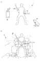
図1(1)に示すように、本実施形態の演奏装置1は、スティック部10R,10Lと、カメラユニット部20と、センターユニット部30と、を含んで構成される。本実施形態のセンターユニット部30は、携帯電話等の小型携帯端末である。本実施形態の演奏装置1は、2本のスティックを用いた仮想的なドラム演奏を実現するため、2つのスティック部10R,10Lを備えることとしているが、スティック部の数は、これに限られず1つとしてもよく、3つ以上としてもよい。なお、以下では、スティック部10R,10Lを個々に区別する必要がない場合には、両者を総称して「スティック部10」と呼ぶ。[Outline of the performance device 1]
First, with reference to FIG. 1, the outline | summary of the
As shown in FIG. 1 (1), the
スティック部10は、長手方向に延びるスティック状の演奏部材である。演奏者は、スティック部10の一端(根元側)を手に持ち、手首などを中心として振り上げたり振り下ろしたりする動作を、演奏動作として行う。このような演奏者の演奏動作を検知するため、スティック部10の他端(先端側)には、加速度センサ及び角速度センサなどの各種センサが設けられている(後述のモーションセンサ部14)。スティック部10は、これらの各種センサにより検知された演奏動作に基づいて、センターユニット部30にノートオンイベントを送信する。
また、スティック部10の先端側には、後述するマーカー部15(図2参照)が設けられており、撮像時にカメラユニット部20がスティック部10の先端を判別可能に構成されている。The
A marker unit 15 (see FIG. 2), which will be described later, is provided on the distal end side of the
カメラユニット部20は、光学式の撮像装置として構成され、スティック部10を保持して演奏動作を行う演奏者を被写体として含む空間(以下、「撮像空間」と呼ぶ)を、所定のフレームレートで撮像し、動画像のデータとして出力する。カメラユニット部20は、撮像空間内における発光中のマーカー部15の位置座標を特定し、当該位置座標を示すデータ(以下、「位置座標データ」と呼ぶ)をセンターユニット部30に送信する。 The
センターユニット部30は、スティック部10からノートオンイベントを受信すると、受信時のマーカー部15の位置座標データに応じて、所定の楽音を発音する。具体的には、センターユニット部30は、カメラユニット部20の撮像空間に対応付けて、図1(2)に示す仮想ドラムセットDの位置座標データを記憶しており、当該仮想ドラムセットDの位置座標データと、ノートオンイベント受信時のマーカー部15の位置座標データとに基づいて、スティック部10が仮想的に打撃した楽器を特定し、当該楽器に対応する楽音を発音する。 When the
次に、このような本実施形態の演奏装置1の構成について具体的に説明する。 Next, the configuration of the
[演奏装置1の構成]
初めに、図2〜図5を参照して、本実施形態の演奏装置1の各構成要素、具体的には、スティック部10、カメラユニット部20及びセンターユニット部30の構成について説明する。[Configuration of the performance device 1]
First, with reference to FIG. 2 to FIG. 5, each component of the
[スティック部10の構成]
図2は、スティック部10のハードウェア構成を示すブロック図である。
図2に示すように、スティック部10は、CPU11(Central Processing Unit)と、ROM(Read Only Memory)12と、RAM(Random Access Memory)13と、モーションセンサ部14と、マーカー部15と、データ通信部16と、スイッチ操作検出回路17と、を含んで構成される。[Configuration of Stick Unit 10]
FIG. 2 is a block diagram illustrating a hardware configuration of the
As shown in FIG. 2, the
CPU11は、スティック部10全体の制御を実行し、例えば、モーションセンサ部14から出力されるセンサ値に基づいて、スティック部10の姿勢の検知、ショット検出及びアクション検出に加え、マーカー部15の発光・消灯などの制御を実行する。このとき、CPU11は、マーカー特徴情報をROM12から読み出し、当該マーカー特徴情報に従い、マーカー部15の発光制御を実行する。また、CPU11は、データ通信部16を介して、センターユニット部30との間の通信制御を実行する。 The
ROM12は、CPU11により各種処理が実行されるための処理プログラムを格納する。また、ROM12は、マーカー部15の発光制御に用いるマーカー特徴情報を格納する。ここで、カメラユニット部20は、スティック部10Rのマーカー部15(以下、「第1マーカー」と適宜呼ぶ)と、スティック部10Lのマーカー部15(以下、「第2マーカー」と適宜呼ぶ)とを区別する必要がある。マーカー特徴情報とは、第1マーカーと第2マーカーとをカメラユニット部20が区別するための情報であり、例えば、発光時の形状、大きさ、色相、彩度、あるいは輝度に加え、発光時の点滅スピードなどを用いることができる。
スティック部10RのCPU11及びスティック部10LのCPU11は、夫々異なるマーカー特徴情報を読み出し、夫々のマーカーの発光制御を実行する。The
The
RAM13は、モーションセンサ部14が出力した各種センサ値など、処理において取得され又は生成された値を格納する。 The
モーションセンサ部14は、スティック部10の状態を検知するための各種センサであり、所定のセンサ値を出力する。ここで、モーションセンサ部14を構成するセンサとしては、例えば、加速度センサ、角速度センサ及び磁気センサなどを用いることができる。 The
図3は、スティック部10の斜視図であり、外部にはスイッチ部171とマーカー部15が配置されている。
演奏者は、スティック部10の一端(根元側)を保持し、手首などを中心とした振り上げ振り下ろし動作を行うことで、スティック部10に対して運動を生じさせる。その際にこの運動に応じたセンサ値がモーションセンサ部14から出力されるようになっている。FIG. 3 is a perspective view of the
The performer holds the one end (base side) of the
モーションセンサ部14からのセンサ値を受け付けたCPU11は、演奏者が持っているスティック部10の状態、を検知する。一例としては、CPU11は、スティック部10による仮想的な楽器の打撃タイミング(以下、「ショットタイミング」とも呼ぶ)を検知する。ショットタイミングは、スティック部10が振り下ろされてから停止される直前のタイミングであり、スティック部10にかかる振り下ろし方向とは逆向きの加速度の大きさがある閾値を超えたタイミングである。 CPU11 which received the sensor value from the
さらに、モーションセンサ部14のセンサ値には、演奏者がスティック部10を持ったときの長手方向と水平面とのなす角である「ピッチ角」及び、当該長手方向と、水平面と直交する面とのなす角である「ヨー角」を検出するために必要なデータも含まれる。 Further, the sensor value of the
図2に戻り、マーカー部15は、スティック部10の先端側に設けられた発光体であり 、例えばLEDなどで構成され、CPU11からの制御に応じて発光及び消灯する。具体的には、マーカー部15は、CPU11によってROM12から読み出されたマーカー特徴情報に基づいて発光する。このとき、スティック部10Rのマーカー特徴情報と、スティック部10Lのマーカー特徴情報とは異なるため、カメラユニット部20は、スティック部10Rのマーカー部(第1マーカー)の位置座標と、スティック部10Lのマーカー部(第2マーカー)の位置座標とを個々に区別し取得することができる。 Returning to FIG. 2, the
データ通信部16は、少なくともセンターユニット部30との間で所定の無線通信を行う。所定の無線通信は、任意の方法で行うこととしてよく、本実施形態では、赤外線通信によりセンターユニット部30との間での無線通信を行う。なお、データ通信部16は、カメラユニット部20との間で無線通信を行うこととしてもよく、また、スティック部10R及びスティック部10Lとの間で無線通信を行うこととしてもよい。 The
スイッチ操作検出回路17は、スイッチ171と接続され、当該スイッチ171を介した入力情報を受け付ける。 The switch
[カメラユニット部20の構成]
スティック部10の構成についての説明は、以上である。続いて、図4を参照して、カメラユニット部20の構成について説明する。
図4は、カメラユニット部20のハードウェア構成を示すブロック図である。
カメラユニット部20は、CPU21と、ROM22と、RAM23と、イメージセンサ部24と、データ通信部25と、を含んで構成される。[Configuration of Camera Unit 20]
This completes the description of the configuration of the
FIG. 4 is a block diagram illustrating a hardware configuration of the
The
CPU21は、カメラユニット部20全体の制御を実行し、例えば、イメージセンサ部24が検出したマーカー部15の位置座標データ及びマーカー特徴情報に基づいて、スティック部10R、10Lのマーカー部15(第1マーカー及び第2マーカー)の夫々の位置座標を算出し、夫々の算出結果を示す位置座標データを出力する制御を実行する。また、CPU21は、データ通信部25を介して、算出した位置座標データなどをセンターユニット部30に送信する通信制御を実行する。 The
ROM22は、CPU21により各種処理が実行されるための処理プログラムを格納する。RAM23は、イメージセンサ部24が検出したマーカー部15の位置座標データなど、処理において取得され又は生成された値を格納する。また、RAM23は、センターユニット部30から受信したスティック部10R、10Lの夫々のマーカー特徴情報も併せて格納する。 The
イメージセンサ部24は、例えば、光学式のカメラであり、スティック部10を持って演奏動作を行う演奏者の動画を所定のフレームレートで撮像する。また、イメージセンサ部24は、フレームごとの撮像データをCPU21に出力する。なお、撮像画像内におけるスティック部10のマーカー部15の位置座標の特定については、イメージセンサ部24が行うこととしてもよく、CPU21が行うこととしてもよい。同様に、撮像したマーカー部15のマーカー特徴情報についても、イメージセンサ部24が特定することとしてもよく、CPU21が特定することとしてもよい。 The
データ通信部25は、少なくともセンターユニット部30との間で所定の無線通信(例えば、赤外線通信)を行う。なお、データ通信部16は、スティック部10との間で無線通信を行うこととしてもよい。 The
[センターユニット部30の構成]
カメラユニット部20の構成についての説明は、以上である。続いて、図5を参照して、センターユニット部30の構成について説明する。
図5は、センターユニット部30のハードウェア構成を示すブロック図である。
センターユニット部30は、CPU31と、ROM32と、RAM33と、スイッチ操作検出回路34と、表示回路35と、音源装置36と、データ通信部37と、タッチパネル制御回路38と、を含んで構成される。[Configuration of Center Unit 30]
This completes the description of the configuration of the
FIG. 5 is a block diagram illustrating a hardware configuration of the
The
CPU31は、センターユニット部30全体の制御を実行し、例えば、スティック部10から受信したショット検出及びカメラユニット部20から受信したマーカー部15の位置座標に基づいて、所定の楽音を発音する制御などを実行する。また、CPU31は、データ通信部37を介して、スティック部10及びカメラユニット部20との間の通信制御を実行する。 The
ROM32は、CPU31の実行する各種処理の処理プログラムを格納する。また、ROM32は、種々の音色の波形データ、例えば、フルート、サックス、トランペットなどの管楽器、ピアノなどの鍵盤楽器、ギターなどの弦楽器、バスドラム、ハイハット、スネア、シンバル、タムなど打楽器の波形データ(音色データ)を、位置座標などと対応付けて格納する。 The
音色データ等の格納方法としては、例えば、図6にセットレイアウト情報として示すように、セットレイアウト情報は、第1パッド〜第nパッドまでのn個のパッド情報を有しており、さらに各パッド情報にパッドの有無(後述する仮想平面における仮想パッドの存在の有無)、位置(後述する仮想平面における位置座標)、高さ(後述する仮想平面からの鉛直上向き方向の距離)、サイズ(仮想パッドの形状及び径など)、音色(波形データ)などが対応づけられて格納されている。
なお、本実施形態においては、上述の高さは、仮想平面からの鉛直上向き方向の距離をおいて仮想的に配置された仮想パッドをスティック部10でショットしようとする場合に、このショットを可能とするスティック部10のピッチ角範囲に対応している。For example, as shown in FIG. 6 as set layout information, the set layout information includes n pieces of pad information from the first pad to the nth pad, and each pad is further stored. Information includes presence / absence of pad (presence / absence of virtual pad on virtual plane described later), position (positional coordinate on virtual plane described later), height (vertical upward distance from virtual plane described later), size (virtual pad) And the like, and tone color (waveform data) are stored in association with each other.
In the present embodiment, the above-described height can be used when a virtual pad virtually arranged at a distance in the vertical upward direction from the virtual plane is shot with the
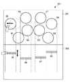
ここで、図7を参照して、具体的なセットレイアウトについて説明する。図7は、センターユニット部30のROM32に格納されたセットレイアウト情報(図6参照)が示す概念を仮想平面上で可視化した図である。
図7は、8個の仮想パッド81〜88が仮想平面上に配置されている様子を示しており、仮想パッド81〜88には、第1パッド〜第nパッドのうち、パッド有無データが「パッド有」となっているものが対応している。例えば、第2パッド、第3パッド、第5パッド、第6パッド、第8パッド、第9パッド、第12パッド、第13パッドの8つが対応している。さらに、位置データ、サイズデータ及び高さデータに基づいて仮想パッド81〜88が配置されている。さらにまた、各仮想パッドに音色データが対応付けられている。したがって、ショット検出時におけるマーカー部15の位置座標が仮想パッド81〜88に対応する領域に属し、かつ、ショット検出時におけるスティック部10のピッチ角が仮想パッド81〜88の夫々について定められたピッチ角の範囲に属した場合、仮想パッド81〜88に対応する音色が発音される。
なお、CPU31は、この仮想平面を仮想パッド81〜88の配置と共に後述する表示装置351に表示する。
また、本実施形態において、この仮想平面での位置座標は、カメラユニット部20の撮像画像での位置座標と一致するものとする。Here, a specific set layout will be described with reference to FIG. FIG. 7 is a diagram in which the concept indicated by the set layout information (see FIG. 6) stored in the
FIG. 7 shows a state in which eight
Note that the
In the present embodiment, the position coordinates on the virtual plane coincide with the position coordinates on the captured image of the
図5に戻って、RAM33は、スティック部10から受信したスティック部10の状態(ショット検出など)、カメラユニット部20から受信したマーカー部15の位置座標、及び、ROM32から読み出されたセットレイアウト情報など、処理において取得され又は生成された値を格納する。
ショット検出時(すなわち、ノートオンイベント受信時)にマーカー部15の位置座標が属する領域の仮想パッド81に対応する音色データ(波形データ)を、RAM33に格納されたセットレイアウト情報から、CPU31が読み出すことで、演奏者の演奏動作に応じた楽音が発音される。Returning to FIG. 5, the
The
スイッチ操作検出回路34は、スイッチ341と接続され、当該スイッチ341を介した入力情報を受け付ける。入力情報としては、例えば、発音する楽音の音量や発音する楽音の音色の変更、セットレイアウト番号の設定及び変更、表示装置351の表示の切り替えなどが含まれる。
また、表示回路35は、表示装置351と接続され、表示装置351の表示制御を実行する。なお、表示装置351は、後述するタッチパネル381を備えている。The switch
The
音源装置36は、CPU31からの指示にしたがって、ROM32から波形データを読み出して、楽音データを生成すると共に、楽音データをアナログ信号に変換し、図示しないスピーカから楽音を発音する。
また、データ通信部37は、スティック部10及びカメラユニット部20との間で所定の無線通信(例えば、赤外線通信)を行う。The
The
タッチパネル制御回路38は、タッチパネル381と接続され、タッチパネル381での接触操作を検出し、検出信号を出力する。この接触操作に応じて、CPU31は、仮想パッドの位置、サイズ、及び高さを調整する。なお、タッチパネル381は、接触操作を検出したら、検出したことを示す信号をタッチパネル制御回路38に出力する。 The touch
[演奏装置1の処理]
以上、演奏装置1を構成するスティック部10、カメラユニット部20及びセンターユニット部30の構成について説明した。続いて、図8〜図11を参照して、演奏装置1の処理について説明する。[Processing of the performance device 1]
In the above, the structure of the
[スティック部10の処理]
図8は、スティック部10が実行する処理(以下、「スティック部処理」と呼ぶ)の流れを示すフローチャートである。
図8を参照して、スティック部10のCPU11は、モーションセンサ部14からモーションセンサ情報、すなわち、各種センサが出力するセンサ値を読み出し、RAM13に格納する(ステップS1)。その後、CPU11は、読み出したモーションセンサ情報に基づいて、スティック部10の姿勢検知処理を実行する(ステップS2)。姿勢検知処理では、CPU11は、モーションセンサ情報に基づいて、スティック部10の姿勢、例えば、スティック部10のロール角及びピッチ角などを算出する。[Processing of the stick unit 10]
FIG. 8 is a flowchart showing a flow of processing executed by the stick unit 10 (hereinafter referred to as “stick unit processing”).
Referring to FIG. 8,
続いて、CPU11は、モーションセンサ情報に基づいて、ショット検出処理を実行する(ステップS3)。ここで、演奏者がスティック部10を用いて演奏を行う場合、一般には、現実の楽器(例えば、ドラム)を打撃する動作と同様の演奏動作を行う。このような演奏動作では、演奏者は、まずスティック部10を振り上げ、それから仮想的な楽器に向かって振り下ろす。そしてスティック部10を仮想的な楽器に打撃する寸前に、スティック部10の動作を止めようとする力を働かせる。このとき、演奏者は、仮想的な楽器にスティック部10を打撃した瞬間に楽音が発生することを想定しているため、演奏者が想定するタイミングで楽音を発生できるのが望ましい。そこで、本実施形態では、演奏者が仮想的な楽器の面にスティック部10を打撃する瞬間又はそのわずかに手前のタイミングで楽音を発音することとしている。 Subsequently, the
本実施形態においては、ショット検出のタイミングは、スティック部10が振り下ろされてから停止される直前のタイミングであり、スティック部10にかかる振り下ろし方向とは逆向きの加速度の大きさがある閾値を超えたタイミングである。
このショット検出のタイミングを発音タイミングとし、発音タイミングが到来したと判断されると、スティック部10のCPU11は、ノートオンイベントを生成し、センターユニット部30に送信する。これにより、センターユニット部30において、発音処理が実行されて、楽音が発音される。
ステップS3に示すショット検出処理では、モーションセンサ情報(例えば、加速度センサのセンサ合成値)に基づいて、ノートオンイベントを生成する。このとき、生成するノートオンイベントには、発音する楽音の音量を含めることとしてもよい。なお、楽音の音量は、例えば、センサ合成値の最大値から求めることができる。In the present embodiment, the shot detection timing is a timing immediately after the
The shot detection timing is set as the sound generation timing. When it is determined that the sound generation timing has arrived, the
In the shot detection process shown in step S3, a note-on event is generated based on motion sensor information (for example, a sensor composite value of an acceleration sensor). At this time, the generated note-on event may include the volume of the musical sound to be generated. The volume of the musical sound can be obtained from the maximum value of the sensor composite value, for example.
続いて、CPU11は、ステップS1乃至ステップS3の処理で検出した情報、すなわち、モーションセンサ情報、姿勢情報及びショット情報を、データ通信部16を介してセンターユニット部30に送信する(ステップS4)。このとき、CPU11は、スティック識別情報と対応付けて、モーションセンサ情報、姿勢情報及びショット情報をセンターユニット部30に送信する。
これにより、処理はステップS1に戻され、それ以降の処理が繰り返される。Subsequently, the
As a result, the process returns to step S1, and the subsequent processes are repeated.
[カメラユニット部20の処理]
図9は、カメラユニット部20が実行する処理(以下、「カメラユニット部処理」と呼ぶ)の流れを示すフローチャートである。
図9を参照して、カメラユニット部20のCPU21は、イメージデータ取得処理を実行する(ステップS11)。この処理では、CPU21は、イメージセンサ部24からイメージデータを取得する。[Processing of Camera Unit 20]
FIG. 9 is a flowchart showing a flow of processing (hereinafter referred to as “camera unit section processing”) executed by the
Referring to FIG. 9, the
続いて、CPU21は、第1マーカー検出処理(ステップS12)及び第2マーカー検出処理(ステップS13)を実行する。これらの処理では、CPU21は、イメージセンサ部24が検出した、スティック部10Rのマーカー部15(第1マーカー)及びスティック部10Lのマーカー部15(第2マーカー)の位置座標、サイズ、角度などのマーカー検出情報を、取得しRAM23に格納する。このとき、イメージセンサ部24は、発光中のマーカー部15について、マーカー検出情報を検出する。 Subsequently, the
続いて、CPU21は、ステップS12及びステップS13で取得したマーカー検出情報を、データ通信部25を介してセンターユニット部30に送信し(ステップS14)、ステップS11に処理を移行させる。 Then, CPU21 transmits the marker detection information acquired by step S12 and step S13 to the
[センターユニット部30の処理]
図10は、センターユニット部30が実行する処理(以下、「センターユニット部処理」と呼ぶ)の流れを示すフローチャートである。[Processing of Center Unit 30]
FIG. 10 is a flowchart showing a flow of processing (hereinafter referred to as “center unit section processing”) executed by the
図10を参照して、センターユニット部30のCPU31は、カメラユニット部20から、第1マーカー及び第2マーカー夫々のマーカー検出情報を受信し、RAM33に格納する(ステップS21)。また、CPU31は、スティック部10R、10Lの夫々から、スティック識別情報と対応付けられたモーションセンサ情報、姿勢情報及びショット情報を受信し、RAM33に格納する(ステップS22)。さらに、CPU31は、スイッチ341の操作により入力された情報を取得する(ステップS23)。 Referring to FIG. 10, the
続いて、CPU31は、ショットありか否かを判断する(ステップS24)。この処理では、CPU31は、スティック部10からノートオンイベントを受信したか否かにより、ショットの有無を判断する。このとき、ショットありと判断した場合には、CPU31は、ショット情報処理を実行する(ステップS25)。ショットなしと判断した場合には、CPU31は、処理をステップS21に移行させる。
ショット情報処理では、CPU31は、RAM33に読み出されたセットレイアウト情報に基づいて、マーカー検出情報に含まれる位置座標が仮想パッド81〜88のいずれかに属するか否かを判断する。属すると判断された場合には、RAM33に格納された姿勢情報に含まれるピッチ角が、属すると判断された仮想パッドに対応するピッチ角の範囲に属するか否かを、RAM33に読み出されたセットレイアウト情報に基づいて判断する。この判断でも属すると判断された場合には、先の判断で属すると判断された仮想パッドに対応する音色データ(波形データ)を読み出し、ノートオンイベントに含まれる音量データと共に音源装置36に出力する。すると、音源装置36は、受け取った波形データに基づいて該当する楽音を発音する。Subsequently, the
In the shot information processing, the
続いて、CPU31は、ショットタイミングにおけるショット結果を表示する(ステップS26)。ショット結果の表示については、図11及び図12を参照して後述する。ステップS26の処理が終了すると、CPU31は、センターユニット部処理を終了する。 Subsequently, the
[ショット結果の表示例]
図11は、ショット結果の表示例をピッチ角に基づいて示す図であり、演奏者が仮想パッド81又は仮想パッド85をショットしようと試みたが、仮想パッド81又は仮想パッド85に対応する音色で発音されなかった場合の表示例が示されている。図11(a)では、ショットタイミングでのスティック部10のピッチ角がスティック部10自体の姿勢を表示することにより示されている。図11(b)では、ショットタイミングでのスティック部10のピッチ角が何度であるかが具体的な数値で示されている。
演奏者は、これらの表示を見ることにより、仮想パッド81又は仮想パッド85をショットするためには、どのくらいのピッチ角でショットすればよいのか等を学習することができる。例えば、仮想パッド81をショットするためには、ピッチ角を0°〜15°の範囲にすること、仮想パッド85をショットするためには、ピッチ角を45°〜60°の範囲にすること、及び今回のピッチ角が30°であったこと等を学習できる。[Example of shot result display]
FIG. 11 is a diagram showing a display example of the shot result based on the pitch angle, and the performer tried to shot the
By viewing these displays, the performer can learn how much pitch angle should be used to shot the
図12は、ショット結果の表示例をヨー角に基づいて示す図である。図12によれば、ショットタイミングにおいてスティック部10は仮想パッド84をショットしたことを示しており、さらに、スティック部10の水平面と直交する面との角度がRAM33に格納された姿勢情報のヨー角として、スティック部10自体の姿勢を表示することにより示されている。演奏者は、この表示を見ることで、例えば、仮想パッド83をショットするためには、ヨー角をどのくらい調節すればよいのか等を学習できる。 FIG. 12 is a diagram illustrating a display example of shot results based on the yaw angle. 12 shows that the
[セットレイアウト情報の位置、サイズ及び高さの調整]
図13〜図17の説明において、上述したタッチパネル381における接触操作に基づいて、CPU31が、仮想パッド81〜88等の画像を、表示回路35を介して表示装置351に表示する。[Adjustment of position, size and height of set layout information]
13 to 17, the
図13は、セットレイアウト情報の位置、サイズ、及び高さに基づいて、仮想パッド81〜88の配置が表示装置351に表示された様子を示す図である。演奏者は、各仮想パッドの表示領域を指でタッチしてドラッグすることによって、左右方向及び高さ方向を調整できる。これにより、各仮想パッドの左右方向及び高さ方向の調整を直感的で分かり易く行うことができる。 FIG. 13 is a diagram illustrating a state in which the arrangement of the
しかし、この方法では、表示装置351の一画像領域で左右方向及び高さ方向を調整するため、携帯電話等の小型携帯端末であるセンターユニット30の表示装置351のような小さな画面では、タッチ操作が複雑になり、誤操作によるミスが起こり易い。そこで、表示装置351の画像領域を2つの領域に分けてセットレイアウト情報の変更を行う方法、図14〜図17を参照して説明する。 However, in this method, since the horizontal direction and the height direction are adjusted in one image area of the
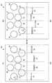
図14は、セットレイアウト情報の位置、サイズ及び高さに基づいて、仮想パッド81〜88の夫々の配置が表示装置351に表示された様子を示す図である。表示装置351の表示領域は、配置表示領域361及び高さ表示領域362に分かれている。配置表示領域361には、セットレイアウト情報の位置、サイズに基づいた仮想パッド81〜88の夫々の配置が表示され、高さ表示領域362には、仮想パッド85〜88の夫々に対応する高さ調整アイコン95〜98が表示されている。
例えば、仮想パッド85を例として説明すると、演奏者は、仮想パッド85の領域をタッチして左右方向にドラッグすることで仮想パッド85の位置を左右方向に移動させる調整を行うことができ、仮想パッド85に対応する高さ調整アイコン95をタッチして高さ方向にドラッグすることで仮想パッド85の高さを調整できる。なお、他の仮想パッドについても以降の説明を含めて同様である。FIG. 14 is a diagram illustrating a state in which the arrangement of the
For example, taking the
また、図15に示すように、仮想パッド85の領域をタッチして左方向へドラッグして仮想パッド85の位置が移動した場合、それに追従するように高さ調整アイコン95の位置も移動する。 In addition, as shown in FIG. 15, when the position of the
さらに、図16に示すように、仮想パッド85の領域を2本の指でタッチして互いに離反する方向に2本の指を移動させて、仮想パッド85のサイズが大きくなった場合、それに追従するように高さ調整アイコン95の幅も大きくなる。また、図示していないが、2本の指を互いに近づける方向に移動させると、仮想パッド85のサイズは小さくなり、それに追従するように高さ調整アイコン95の幅も小さくなる。 Further, as shown in FIG. 16, when the size of the
さらにまた、図17に示すように、仮想パッド81〜88は、仮想パッド81〜84と仮想パッド85〜88との2つのグループに分かれており、仮想パッド81〜84のいずれかがタッチされることにより、仮想パッド81〜84の夫々に対応する高さ調整アイコン91〜94が表示され、仮想パッド81〜84の高さを調整できる。その後、仮想パッド85〜88のいずれかがタッチされることにより、高さ調整アイコン95〜98が表示され、仮想パッド85〜88の高さを再び調整できる。このように、仮想パッドのグループ毎に高さ調整アイコンの表示を切り替えることができる。なお、仮想パッドのグループ数は3つ以上であってもよい。 Furthermore, as shown in FIG. 17, the
以上、本実施形態の演奏装置1の構成及び処理について説明した。
本実施形態においては、CPU31は、スティック部10によるショットタイミングにおいて、スティック部10の位置座標が、セットレイアウト情報に基づいて配置された仮想パッド81〜88のいずれかに属したか否かを判別し、属すると判別された場合に、スティック部10のピッチ角が、当該仮想パッドに対応する高さに応じた所定範囲に属するか否かを判別し、当該所定範囲に属すると判別された場合に、当該仮想パッドに対応する音色の楽音の発音を指示する。
よって、セットレイアウト情報の各仮想パッドにピッチ角等の情報を対応させることにより、演奏者がリアルな演奏感覚を得ることができる。The configuration and processing of the
In the present embodiment, the
Therefore, by making information such as the pitch angle correspond to each virtual pad of the set layout information, the player can obtain a realistic performance feeling.
また、本実施形態においては、CPU31は、スティック部10によるショットタイミングにおいて、スティック部10のピッチ角を報知する。
よって、演奏者は、ショットタイミングにおけるピッチ角を確認できる。In the present embodiment, the
Therefore, the performer can confirm the pitch angle at the shot timing.
また、本実施形態においては、CPU31は、スティック部10によるショットタイミングにおいて、スティック部10のピッチ角が仮想パッド81〜88の夫々に対応する所定範囲に属すると判別されなかった場合にスティック部10のピッチ角を報知する。
よって、演奏者は、ショットタイミングにおけるピッチ角を確認することで、ピッチ角をどのように修正すれば的確に狙った仮想パッドをショットできるか学習できる。In the present embodiment, the
Therefore, the performer can learn how to correct the pitch angle to be shot accurately by checking the pitch angle at the shot timing.
また、本実施形態においては、仮想パッド81〜88夫々の領域の配置を表示する配置表示領域361と、仮想パッド81〜88夫々の高さを示す高さ調整アイコン91〜98を表示する高さ表示領域362と、を同一画面上の異なる領域に表示する表示装置351と、表示装置351における接触操作を検出して、検出したことを示す信号を出力するタッチパネル381と、を備え、CPU31は、タッチパネル381から配置表示領域361における接触操作を検出したことを示す信号を受信した場合に、配置表示領域361における接触位置と、配置表示領域361に表示された仮想パッド81〜88夫々の領域の配置とに基づいて、仮想パッド81〜88のうちいずれかの領域の配置を調整し、タッチパネル381から高さ表示領域362における接触操作を検出したことを示す信号を受信した場合に、高さ表示領域362における接触位置と、高さ表示領域362に表示された高さ調整アイコン91〜98とに基づいて仮想パッド81〜88のうちいずれかの高さを調整する。
よって、高さやピッチ角等の立体的な情報を有するレイアウト情報を変更する際に、仮想パッドの左右方向への移動と高さ方向の調整とを画面上の異なる領域で行うことにより、レイアウト情報の変更操作を容易に行うことができる。Moreover, in this embodiment, the height which displays the arrangement | positioning
Therefore, when changing layout information having three-dimensional information such as height and pitch angle, the layout information is obtained by moving the virtual pad in the horizontal direction and adjusting the height direction in different areas on the screen. Can be easily changed.
また、本実施形態においては、高さ表示領域362に表示された高さ調整アイコン91〜98は、配置表示領域361に表示された仮想パッド81〜88夫々の領域の配置に対応して表示される。
よって、演奏者は、どの高さ調整アイコンをタッチして仮想パッドの高さを調整すればよいか容易に把握できる。In the present embodiment, the
Therefore, the performer can easily grasp which height adjustment icon to touch to adjust the height of the virtual pad.
また、本実施形態においては、高さ表示領域362に表示された高さ調整アイコン91〜98は、配置表示領域361に表示された仮想パッド81〜88夫々の領域の配置が調整された場合、この調整された配置に追従して表示される。
よって、演奏者は、仮想パッドの配置が調整された場合であっても、どの高さ調整アイコンをタッチして仮想パッドの高さを調整すればよいか容易に把握できる。In the present embodiment, the
Therefore, even if the arrangement of the virtual pad is adjusted, the performer can easily grasp which height adjustment icon should be touched to adjust the height of the virtual pad.
以上、本発明の実施形態について説明したが、実施形態は例示に過ぎず、本発明の技術的範囲を限定するものではない。本発明はその他の様々な実施形態を取ることが可能であり、さらに、本発明の要旨を逸脱しない範囲で、省略や置換など種々の変更を行うことができる。これら実施形態やその変形は、本明細書などに記載された発明の範囲や要旨に含まれると共に、特許請求の範囲に記載された発明とその均等の範囲に含まれる。 As mentioned above, although embodiment of this invention was described, embodiment is only an illustration and does not limit the technical scope of this invention. The present invention can take other various embodiments, and various modifications such as omission and replacement can be made without departing from the gist of the present invention. These embodiments and modifications thereof are included in the scope and gist of the invention described in this specification and the like, and are included in the invention described in the claims and the equivalents thereof.
即ち、本発明が適用される演奏装置は、上記実施形態に特に限定されず、次のような構成を有するように各種各様の実施形態を取ることができる。
即ち、演奏装置は、
演奏者が保持可能な演奏部材と、
演奏操作時における前記演奏部材のピッチ角を検出するピッチ角検出手段と、
前記演奏部材を被写体とする撮像画像を撮像すると共に、前記撮像画像平面上の前記演奏部材の位置座標を検出する撮像装置と、
前記撮像画像平面上に配置された複数の領域及び当該複数の領域夫々に対応するピッチ角範囲を含むレイアウト情報を記憶する記憶手段と、
前記演奏部材により演奏操作がなされたタイミングにおいて、前記演奏部材の位置座標が、前記記憶手段に記憶されたレイアウト情報に基づいて前記撮像画像平面上に配置された複数の領域のいずれかに属するか否かを判別する第1判別手段と、
前記第1判別手段により領域に属すると判別された場合に、前記ピッチ角検出手段により検出された前記演奏部材のピッチ角が、当該領域に対応するピッチ角範囲に属するか否かを判別する第2判別手段と、
前記第2判別手段により当該領域に対応するピッチ角範囲に属すると判別された場合に、当該領域に対応する楽音の発音を指示する発音指示手段と、を備える、ように構成することができる。
このような構成を有する演奏装置では、レイアウト情報の複数の領域夫々にピッチ角範囲の情報を対応させることにより、演奏者がリアルな演奏感覚を得ることができる。That is, the performance device to which the present invention is applied is not particularly limited to the above-described embodiment, and various various embodiments can be adopted so as to have the following configuration.
In other words, the performance device
A performance member that the performer can hold;
Pitch angle detecting means for detecting the pitch angle of the performance member during performance operation;
An imaging device that captures a captured image of the performance member as a subject and detects position coordinates of the performance member on the captured image plane;
Storage means for storing layout information including a plurality of areas arranged on the captured image plane and a pitch angle range corresponding to each of the plurality of areas;
Whether the position coordinates of the performance member belong to any of a plurality of areas arranged on the captured image plane based on the layout information stored in the storage means at the timing when the performance operation is performed by the performance member First determining means for determining whether or not,
When it is determined by the first determining means that it belongs to an area, it is determined whether or not the pitch angle of the performance member detected by the pitch angle detecting means belongs to a pitch angle range corresponding to the area. 2 discriminating means;
And a sound generation instruction means for instructing the sound generation of the musical sound corresponding to the area when it is determined by the second determination means to belong to the pitch angle range corresponding to the area.
In the performance device having such a configuration, the player can obtain a realistic performance feeling by associating the information of the pitch angle range with each of the plurality of areas of the layout information.
さらに、演奏装置は、
前記演奏部材により前記演奏操作がなされたタイミングにおいて、前記演奏部材のピッチ角を報知する報知手段をさらに備える、ように構成することもできる。
よって、演奏者は、演奏操作時におけるピッチ角を確認できる。Furthermore, the performance device
It is also possible to further comprise notifying means for notifying the pitch angle of the performance member at the timing when the performance operation is performed by the performance member.
Therefore, the performer can confirm the pitch angle during the performance operation.
さらに、演奏装置は、
前記報知手段は、前記第2判別手段により前記ピッチ角範囲に属すると判別されなかった場合に前記演奏部材のピッチ角を報知する、ように構成することもできる。
よって、演奏者は、演奏操作時におけるピッチ角を確認することで、ピッチ角をどのように修正すれば的確に狙った領域を演奏できるか学習できる。Furthermore, the performance device
The notifying means may be configured to notify the pitch angle of the performance member when the second determining means does not determine that it belongs to the pitch angle range.
Therefore, the performer can learn how to correct the pitch angle by accurately checking the pitch angle at the time of the performance operation.
また、演奏装置は、
演奏者が保持可能な演奏部材と、
前記演奏部材を被写体とする撮像画像を撮像すると共に、前記撮像画像平面上の前記演奏部材の位置座標を検出する撮像装置と、
前記撮像画像平面上に配置される複数の領域夫々の位置及び当該複数の領域夫々を立体表示する場合の高さに対応する高さデータを含むレイアウト情報を記憶する記憶手段と、
当該レイアウト情報の複数の領域夫々の前記撮像平面における配置と、当該レイアウト情報の複数の領域夫々の高さとを調整するレイアウト情報調整手段と、
前記演奏部材により特定の演奏操作がなされたタイミングにおいて、前記演奏部材の位置座標が、前記レイアウト情報に基づいて前記撮像画像平面上に配置された複数の領域のいずれかに属するか否かを判別する判別手段と、
この判別手段により領域に属すると判別された場合に、当該領域に対応する楽音の発音を指示する発音指示手段と、
所定の表示手段の配置表示領域に前記複数の領域夫々の前記撮像平面上の配置を表示させるとともに、前記表示手段の高さ表示領域に前記複数の領域夫々を立体表示した場合の高さを示す画像を表示させる表示制御手段と、
前記表示手段上における接触操作を検出するタッチパネルと、
を備え、
前記レイアウト情報調整手段は、
前記配置表示領域の画面上にて接触操作を検出した場合に、前記配置表示領域における接触位置と、前記配置表示領域に表示された前記複数の領域夫々の前記撮像平面上における位置とに基づいて、前記複数の領域のいずれかの前記撮像平面上の位置を調整する配置調整手段と、
前記高さ表示領域の画面上にて接触操作を検出した場合に、前記高さ表示領域における接触位置と、前記高さ表示領域に表示された前記複数の領域夫々を立体表示した場合の高さを示す画像の位置とに基づいて、前記複数の領域のいずれかの高さを示す画像の位置を調整する高さ調整手段と、を備える、ように構成することができる。
このような演奏装置では、高さのような立体的な情報を有するレイアウト情報を変更する際に、領域の左右方向への移動と高さ方向の調整とを表示手段の異なる領域で行うことにより、レイアウト情報の変更操作を容易に行うことができる。Also, the performance device
A performance member that the performer can hold;
An imaging device that captures a captured image of the performance member as a subject and detects position coordinates of the performance member on the captured image plane;
Storage means for storing layout information including the position of each of a plurality of areas arranged on the captured image plane and height data corresponding to the height when each of the plurality of areas is stereoscopically displayed;
Layout information adjusting means for adjusting the arrangement of each of the plurality of regions of the layout information in the imaging plane and the height of each of the plurality of regions of the layout information;
At a timing when a specific performance operation is performed by the performance member, it is determined whether or not the position coordinates of the performance member belong to any one of a plurality of areas arranged on the captured image plane based on the layout information. Discriminating means to perform,
A sounding instruction means for instructing the sound generation of the musical sound corresponding to the area when the determination means determines that the sound belongs to the area;
The arrangement display area of the predetermined display means displays the arrangement of the plurality of areas on the imaging plane, and indicates the height when each of the plurality of areas is stereoscopically displayed in the height display area of the display means. Display control means for displaying an image;
A touch panel for detecting a contact operation on the display means;
With
The layout information adjusting means includes
When a contact operation is detected on the screen of the arrangement display area, based on the contact position in the arrangement display area and the position on the imaging plane of each of the plurality of areas displayed in the arrangement display area , Arrangement adjusting means for adjusting the position of any one of the plurality of regions on the imaging plane;
When a contact operation is detected on the screen of the height display area, the contact position in the height display area and the height when each of the plurality of areas displayed in the height display area is stereoscopically displayed. And a height adjusting means for adjusting the position of the image indicating the height of any one of the plurality of regions based on the position of the image indicating.
In such a performance device, when changing layout information having three-dimensional information such as height, the horizontal movement of the area and the adjustment in the height direction are performed in different areas of the display means. The layout information can be easily changed.
さらに、演奏装置は、
前記高さ表示領域に表示された前記複数の領域夫々の高さを示す画像は前記高さ表示領域内でかつ、前記配置表示領域に表示された前記複数の領域夫々の配置に対応した位置に表示される、ように構成することもできる。
よって、演奏者は、複数の領域夫々を立体表示した場合の高さを示す画像のうちどの画像を接触操作すれば所望の領域について高さを調整できるのかを容易に把握できる。Furthermore, the performance device
The image indicating the height of each of the plurality of areas displayed in the height display area is in a position corresponding to the arrangement of each of the plurality of areas displayed in the arrangement display area in the height display area. It can also be configured to be displayed.
Therefore, the performer can easily grasp which of the images indicating the height when each of the plurality of areas is stereoscopically displayed is touched to adjust the height of the desired area.
上記実施形態では、仮想的な打楽器として仮想ドラムセットD(図1参照)を例にとって説明したが、これに限られるものではなく、本発明は、スティック部10の振り下ろし動作で楽音を発音する木琴など他の楽器に適用することができる。 In the above embodiment, the virtual drum set D (see FIG. 1) has been described as an example of a virtual percussion instrument. However, the present invention is not limited to this, and the present invention generates a musical tone by swinging down the
以下に、本願の出願当初の特許請求の範囲に記載された発明を付記する。
[付記1]
演奏者が保持可能な演奏部材と、
演奏操作時における前記演奏部材のピッチ角を検出するピッチ角検出手段と、
前記演奏部材を被写体とする撮像画像を撮像すると共に、前記撮像画像平面上の前記演奏部材の位置座標を検出する撮像装置と、
前記撮像画像平面上に配置された複数の領域及び当該複数の領域夫々に対応するピッチ角範囲を含むレイアウト情報を記憶する記憶手段と、
前記演奏部材により演奏操作がなされたタイミングにおいて、前記演奏部材の位置座標が、前記記憶手段に記憶されたレイアウト情報に基づいて前記撮像画像平面上に配置された複数の領域のいずれかに属するか否かを判別する第1判別手段と、
前記第1判別手段により領域に属すると判別された場合に、前記ピッチ角検出手段により検出された前記演奏部材のピッチ角が、当該領域に対応するピッチ角範囲に属するか否かを判別する第2判別手段と、
前記第2判別手段により当該領域に対応するピッチ角範囲に属すると判別された場合に、当該領域に対応する楽音の発音を指示する発音指示手段と、を備える、
ことを特徴とする演奏装置。
[付記2]
前記演奏部材により前記演奏操作がなされたタイミングにおいて、前記演奏部材のピッチ角を報知する報知手段をさらに備える、
ことを特徴とする付記1に記載の演奏装置。
[付記3]
前記報知手段は、前記第2判別手段により前記ピッチ角範囲に属すると判別されなかった場合に前記演奏部材のピッチ角を報知する、
ことを特徴とする付記2に記載の演奏装置。
[付記4]
演奏者が保持可能な演奏部材と、前記演奏部材を被写体とする撮像画像を撮像すると共に、前記撮像画像平面上の前記演奏部材の位置座標を検出する撮像装置と、前記撮像画像平面に配置された複数の領域及び当該複数の領域夫々に対応するピッチ角範囲を含むレイアウト情報を記憶する記憶手段と、を有する演奏装置として用いられるコンピュータに、
演奏操作時における前記演奏部材のピッチ角を検出するステップと、
前記演奏部材により演奏操作がなされたタイミングにおいて、前記演奏部材の位置座標が、前記記憶手段に記憶されたレイアウト情報に基づいて前記撮像画像平面上に配置された複数の領域のいずれかに属するか否かを判別するステップと、
前記いずれかの領域に属すると判別された場合に、前記検出された前記演奏部材のピッチ角が、当該領域に対応するピッチ角範囲に属するか否かを判別するステップと、
当該領域に対応するピッチ角範囲に属すると判別された場合に、当該領域に対応する楽音の発音を指示するステップと、
を実行させるプログラム。
[付記5]
演奏者が保持可能な演奏部材と、
前記演奏部材を被写体とする撮像画像を撮像すると共に、前記撮像画像平面上の前記演奏部材の位置座標を検出する撮像装置と、
前記撮像画像平面上に配置される複数の領域夫々の位置及び当該複数の領域夫々を立体表示する場合の高さに対応する高さデータを含むレイアウト情報を記憶する記憶手段と、
当該レイアウト情報の複数の領域夫々の前記撮像平面における配置と、当該レイアウト情報の複数の領域夫々の高さとを調整するレイアウト情報調整手段と、
前記演奏部材により特定の演奏操作がなされたタイミングにおいて、前記演奏部材の位置座標が、前記レイアウト情報に基づいて前記撮像画像平面上に配置された複数の領域のいずれかに属するか否かを判別する判別手段と、
この判別手段により領域に属すると判別された場合に、当該領域に対応する楽音の発音を指示する発音指示手段と、
所定の表示手段の配置表示領域に前記複数の領域夫々の前記撮像平面上の配置を表示させるとともに、前記表示手段の高さ表示領域に前記複数の領域夫々を立体表示した場合の高さを示す画像を表示させる表示制御手段と、
前記表示手段上における接触操作を検出するタッチパネルと、
を備え、
前記レイアウト情報調整手段は、
前記配置表示領域の画面上にて接触操作を検出した場合に、前記配置表示領域における接触位置と、前記配置表示領域に表示された前記複数の領域夫々の前記撮像平面上における位置とに基づいて、前記複数の領域のいずれかの前記撮像平面上の位置を調整する配置調整手段と、
前記高さ表示領域の画面上にて接触操作を検出した場合に、前記高さ表示領域における接触位置と、前記高さ表示領域に表示された前記複数の領域夫々を立体表示した場合の高さを示す画像の位置とに基づいて、前記複数の領域のいずれかの高さを示す画像の位置を調整する高さ調整手段と、を備える、
ことを特徴とする演奏装置。
[付記6]
前記高さ表示領域に表示された前記複数の領域夫々の高さを示す画像は前記高さ表示領域内でかつ、前記配置表示領域に表示された前記複数の領域夫々の配置に対応した位置に表示される、
ことを特徴とする付記5に記載の演奏装置。The invention described in the scope of claims at the beginning of the filing of the present application will be appended.
[Appendix 1]
A performance member that the performer can hold;
Pitch angle detecting means for detecting the pitch angle of the performance member during performance operation;
An imaging device that captures a captured image of the performance member as a subject and detects position coordinates of the performance member on the captured image plane;
Storage means for storing layout information including a plurality of areas arranged on the captured image plane and a pitch angle range corresponding to each of the plurality of areas;
Whether the position coordinates of the performance member belong to any of a plurality of areas arranged on the captured image plane based on the layout information stored in the storage means at the timing when the performance operation is performed by the performance member First determining means for determining whether or not,
When it is determined by the first determining means that it belongs to an area, it is determined whether or not the pitch angle of the performance member detected by the pitch angle detecting means belongs to a pitch angle range corresponding to the area. 2 discriminating means;
Sound generation instruction means for instructing sound generation of a musical sound corresponding to the area when the second determination means determines that it belongs to the pitch angle range corresponding to the area;
A performance apparatus characterized by that.
[Appendix 2]
A notification means for notifying a pitch angle of the performance member at a timing when the performance operation is performed by the performance member;
The performance device according to
[Appendix 3]
The notifying means notifies the pitch angle of the performance member when the second determining means does not determine that it belongs to the pitch angle range;
The performance device according to
[Appendix 4]
A performance member that can be held by a performer, an imaging device that captures a captured image of the performance member as a subject, and that detects a position coordinate of the performance member on the captured image plane, and is disposed on the captured image plane A storage unit storing layout information including a plurality of regions and a pitch angle range corresponding to each of the plurality of regions, and a computer used as a performance device,
Detecting a pitch angle of the performance member during performance operation;
Whether the position coordinates of the performance member belong to any of a plurality of areas arranged on the captured image plane based on the layout information stored in the storage means at the timing when the performance operation is performed by the performance member Determining whether or not,
Determining whether the detected pitch angle of the performance member belongs to a pitch angle range corresponding to the region when it is determined that the region belongs to any one of the regions;
Instructing the pronunciation of a musical sound corresponding to the area when it is determined that the pitch angle range corresponds to the area; and
A program that executes
[Appendix 5]
A performance member that the performer can hold;
An imaging device that captures a captured image of the performance member as a subject and detects position coordinates of the performance member on the captured image plane;
Storage means for storing layout information including the position of each of a plurality of areas arranged on the captured image plane and height data corresponding to the height when each of the plurality of areas is stereoscopically displayed;
Layout information adjusting means for adjusting the arrangement of each of the plurality of regions of the layout information in the imaging plane and the height of each of the plurality of regions of the layout information;
At a timing when a specific performance operation is performed by the performance member, it is determined whether or not the position coordinates of the performance member belong to any one of a plurality of areas arranged on the captured image plane based on the layout information. Discriminating means to perform,
A sounding instruction means for instructing the sound generation of the musical sound corresponding to the area when the determination means determines that the sound belongs to the area;
The arrangement display area of the predetermined display means displays the arrangement of the plurality of areas on the imaging plane, and indicates the height when each of the plurality of areas is stereoscopically displayed in the height display area of the display means. Display control means for displaying an image;
A touch panel for detecting a contact operation on the display means;
With
The layout information adjusting means includes
When a contact operation is detected on the screen of the arrangement display area, based on the contact position in the arrangement display area and the position on the imaging plane of each of the plurality of areas displayed in the arrangement display area , Arrangement adjusting means for adjusting the position of any one of the plurality of regions on the imaging plane;
When a contact operation is detected on the screen of the height display area, the contact position in the height display area and the height when each of the plurality of areas displayed in the height display area is stereoscopically displayed. A height adjusting means for adjusting the position of the image indicating the height of any of the plurality of regions based on the position of the image indicating
A performance apparatus characterized by that.
[Appendix 6]
The image indicating the height of each of the plurality of areas displayed in the height display area is in a position corresponding to the arrangement of each of the plurality of areas displayed in the arrangement display area in the height display area. Is displayed,
The performance device according to appendix 5, characterized in that:
1・・・演奏装置、10・・・スティック部、11・・・CPU、12・・・ROM、13・・・RAM、14・・・モーションセンサ部、15・・・マーカー部、16・・・データ通信部、17・・・スイッチ操作検出回路、171・・・スイッチ、20・・・カメラユニット部、21・・・CPU、22・・・ROM、23・・・RAM、24・・・イメージセンサ部、25・・・データ通信部、30・・・センターユニット、31・・・CPU、32・・ROM、33・・・RAM、34・・・スイッチ操作検出回路、341・・・スイッチ、35・・・表示回路、351・・・表示装置、36・・・音源装置、37・・・データ通信部、38・・・タッチパネル制御回路、381・・・タッチパネル、81〜88・・・仮想パッド、91〜98・・・高さ調整アイコン、361・・・配置表示領域、362・・・高さ表示領域 DESCRIPTION OF
Claims (6)
Translated fromJapanese演奏者が保持可能な演奏部材の、演奏操作時におけるピッチ角を検出するピッチ角センサと、
前記演奏部材を、所定の撮像平面上における被写体として撮像画像を撮像すると共に、当該撮像平面を前記仮想平面として前記演奏部材の位置座標を検出する撮像装置と、
所定の表示手段の配置表示領域に前記複数の領域夫々の前記撮像平面上の配置を表示させる表示制御手段と、
前記演奏部材により演奏操作がなされたタイミングにおいて、前記演奏部材の位置座標が、前記メモリに記憶されたレイアウト情報に基づいて前記仮想平面上に配置された複数の領域のいずれかに属するか否かを判別する第1判別手段と、
前記第1判別手段により領域に属すると判別された場合に、前記ピッチ角センサにより検出された前記演奏部材のピッチ角が、当該領域に対応するピッチ角範囲に属するか否かを判別する第2判別手段と、
前記第2判別手段により当該領域に対応するピッチ角範囲に属すると判別された場合に、当該領域に対応する楽音の発音を指示する発音指示手段と、
前記第2判別手段により前記ピッチ角範囲に属すると判別されなかった場合に前記演奏部材のピッチ角を前記所定の表示手段に表示するピッチ角表示手段と、
を備える、
ことを特徴とする演奏装置。A memory for storing layout information including a plurality of regions arranged on a predetermined virtual plane and a pitch angle range corresponding to each of the plurality of regions;
A pitch angle sensor that detects a pitch angle of a performance member that can be held by the performer during a performance operation;
An imaging device that captures a captured image as a subject on a predetermined imaging plane, and detects position coordinates of the performance member using the imaging plane as the virtual plane;
Display control means for displaying an arrangement on the imaging plane of each of the plurality of areas in an arrangement display area of a predetermined display means;
Whether or not the position coordinates of the performance member belong to any of a plurality of areas arranged on the virtual plane based on the layout information stored in the memory at the timing when the performance operation is performed by the performance member First discriminating means for discriminating;
A second determining unit configured to determine whether or not a pitch angle of the performance member detected by the pitch angle sensor belongs to a pitch angle range corresponding to the region when the first determining unit determines that the pitch member belongs to the region; Discrimination means;
A sounding instruction means for instructing sound generation of a musical sound corresponding to the area when the second determining means determines that the sound belongs to the pitch angle range corresponding to the area;
A pitch angle display means for displaying the pitch angle of the performance member on the predetermined display means when it is not determined by the second determination means to belong to the pitch angle range;
Comprising
A performance apparatus characterized by that.
前記表示制御手段はさらに、前記所定の表示手段の高さ表示領域に前記複数の領域夫々を立体表示した場合の高さを示す画像を表示させる表示制御手段を有する、請求項1記載の演奏装置。The layout information further includes height data corresponding to the height when each of the plurality of areas is stereoscopically displayed,
2. The performance apparatus according to claim 1, wherein the display control means further includes display control means for displaying an image indicating a height when each of the plurality of areas is stereoscopically displayed in a height display area of the predetermined display means. .
前記レイアウト情報の複数の領域夫々の前記撮像平面における配置と、当該レイアウト情報の複数の領域夫々の高さとを調整するレイアウト情報調整手段を有する、請求項2記載の演奏装置。The performance device further includes
The performance device according to claim 2, further comprising layout information adjustment means for adjusting an arrangement of each of the plurality of areas of the layout information on the imaging plane and a height of each of the plurality of areas of the layout information.
前記レイアウト情報調整手段は、
前記配置表示領域の画面上にて接触操作を検出した場合に、前記配置表示領域における接触位置と、前記配置表示領域に表示された前記複数の領域夫々の前記撮像平面上における位置とに基づいて、前記複数の領域のいずれかの前記撮像平面上の位置を調整する配置調整手段と、
前記高さ表示領域の画面上にて接触操作を検出した場合に、前記高さ表示領域における接触位置と、前記高さ表示領域に表示された前記複数の領域夫々を立体表示した場合の高さを示す画像の位置とに基づいて、前記複数の領域のいずれかの高さを示す画像の位置を調整する高さ調整手段と、
を備える、請求項3に記載の演奏装置。The performance device further includes a touch panel for detecting a contact operation on the display means,
The layout information adjusting means includes
When a contact operation is detected on the screen of the arrangement display area, based on the contact position in the arrangement display area and the position on the imaging plane of each of the plurality of areas displayed in the arrangement display area , Arrangement adjusting means for adjusting the position of any one of the plurality of regions on the imaging plane;
When a contact operation is detected on the screen of the height display area, the contact position in the height display area and the height when each of the plurality of areas displayed in the height display area is stereoscopically displayed. Height adjusting means for adjusting the position of the image indicating the height of any of the plurality of regions based on the position of the image indicating
The performance device according to claim 3, comprising:
所定の表示手段の配置表示領域に前記複数の領域夫々の前記撮像平面上の配置を表示させ、
前記演奏部材により演奏操作がなされたタイミングにおいて、前記演奏部材の位置座標が、前記メモリに記憶されたレイアウト情報に基づいて前記仮想平面上に配置された複数の領域のいずれかに属するか否かを判別し、
前記領域に属すると判別された場合に、前記ピッチ角センサにより検出された前記演奏部材のピッチ角が、当該領域に対応するピッチ角範囲に属するか否かを判別し、
当該領域に対応するピッチ角範囲に属すると判別された場合に、当該領域に対応する楽音の発音を指示し、
前記ピッチ角範囲に属すると判別されなかった場合に前記演奏部材のピッチ角を前記所定の表示手段に表示する、方法。A memory for storing layout information including a plurality of areas arranged on a predetermined virtual plane and a pitch angle range corresponding to each of the plurality of areas, and a performance member that can be held by the performer during performance operation A pitch angle sensor that detects a pitch angle; and an imaging device that captures a captured image using the performance member as a subject on a predetermined imaging plane, and detects position coordinates of the performance member using the imaging plane as the virtual plane; , A method used in a performance device having the performance device,
Displaying the arrangement of each of the plurality of areas on the imaging plane in an arrangement display area of a predetermined display means;
Whether or not the position coordinates of the performance member belong to any of a plurality of areas arranged on the virtual plane based on the layout information stored in the memory at the timing when the performance operation is performed by the performance member Determine
If it is determined that the pitch member belongs to the region, it is determined whether the pitch angle of the performance member detected by the pitch angle sensor belongs to a pitch angle range corresponding to the region;
When it is determined that the pitch angle range corresponding to the area belongs, the sound generation corresponding to the area is instructed,
A method of displaying a pitch angle of the performance member on the predetermined display means when it is not determined that the pitch member belongs to the pitch angle range.
所定の表示手段の配置表示領域に前記複数の領域夫々の前記撮像平面上の配置を表示させる表示制御ステップと、
前記演奏部材により演奏操作がなされたタイミングにおいて、前記演奏部材の位置座標が、前記メモリに記憶されたレイアウト情報に基づいて前記仮想平面上に配置された複数の領域のいずれかに属するか否かを判別する第1判別ステップと、
前記第1判別ステップにより領域に属すると判別された場合に、前記ピッチ角センサにより検出された前記演奏部材のピッチ角が、当該領域に対応するピッチ角範囲に属するか否かを判別する第2判別ステップと、
前記第2判別ステップにより当該領域に対応するピッチ角範囲に属すると判別された場合に、当該領域に対応する楽音の発音を指示する発音指示ステップと、
前記第2判別ステップにより前記ピッチ角範囲に属すると判別されなかった場合に前記演奏部材のピッチ角を前記所定の表示手段に表示するピッチ角表示ステップと、
を実行させるプログラム。A memory for storing layout information including a plurality of areas arranged on a predetermined virtual plane and a pitch angle range corresponding to each of the plurality of areas, and a performance member that can be held by the performer during performance operation A pitch angle sensor that detects a pitch angle; and an imaging device that captures a captured image using the performance member as a subject on a predetermined imaging plane, and detects position coordinates of the performance member using the imaging plane as the virtual plane; In a computer used for a performance device having
A display control step of displaying an arrangement on the imaging plane of each of the plurality of areas in an arrangement display area of a predetermined display means;
Whether or not the position coordinates of the performance member belong to any of a plurality of areas arranged on thevirtual plane based on the layout information stored in the memory at the timing when the performance operation is performed by the performance member A first determination step of determining
When it is determined by the first determination step that the sound member belongs to the area, a second determination is made as to whether or not the pitch angle of the performance member detected by the pitch angle sensor belongs to the pitch angle range corresponding to the area. A determination step;
A sounding instruction step for instructing the sound generation of the musical sound corresponding to the area when it is determined by the second determining step that the sound belongs to the pitch angle range corresponding to the area;
A pitch angle display step of displaying the pitch angle of the performance member on the predetermined display means when the second determination step does not determine that the pitch member belongs to the pitch angle range;
A program that executes
Priority Applications (3)
| Application Number | Priority Date | Filing Date | Title |
|---|---|---|---|
| JP2012061880AJP5598490B2 (en) | 2012-03-19 | 2012-03-19 | Performance device, method and program |
| US13/768,924US9018510B2 (en) | 2012-03-19 | 2013-02-15 | Musical instrument, method and recording medium |
| CN201310051206.2ACN103325363B (en) | 2012-03-19 | 2013-02-16 | Music performance apparatus and method |
Applications Claiming Priority (1)
| Application Number | Priority Date | Filing Date | Title |
|---|---|---|---|
| JP2012061880AJP5598490B2 (en) | 2012-03-19 | 2012-03-19 | Performance device, method and program |
Publications (2)
| Publication Number | Publication Date |
|---|---|
| JP2013195645A JP2013195645A (en) | 2013-09-30 |
| JP5598490B2true JP5598490B2 (en) | 2014-10-01 |
Family
ID=49156461
Family Applications (1)
| Application Number | Title | Priority Date | Filing Date |
|---|---|---|---|
| JP2012061880AActiveJP5598490B2 (en) | 2012-03-19 | 2012-03-19 | Performance device, method and program |
Country Status (3)
| Country | Link |
|---|---|
| US (1) | US9018510B2 (en) |
| JP (1) | JP5598490B2 (en) |
| CN (1) | CN103325363B (en) |
Families Citing this family (20)
| Publication number | Priority date | Publication date | Assignee | Title |
|---|---|---|---|---|
| JP5549698B2 (en) | 2012-03-16 | 2014-07-16 | カシオ計算機株式会社 | Performance device, method and program |
| JP5942627B2 (en)* | 2012-06-18 | 2016-06-29 | カシオ計算機株式会社 | Performance device, method and program |
| JP6398291B2 (en)* | 2014-04-25 | 2018-10-03 | カシオ計算機株式会社 | Performance device, performance method and program |
| CN105807907B (en)* | 2014-12-30 | 2018-09-25 | 富泰华工业(深圳)有限公司 | Body-sensing symphony performance system and method |
| US9418639B2 (en)* | 2015-01-07 | 2016-08-16 | Muzik LLC | Smart drumsticks |
| EP3243198A4 (en)* | 2015-01-08 | 2019-01-09 | Muzik LLC | INTERACTIVE INSTRUMENTS AND OTHER STRIKING OBJECTS |
| US9520117B2 (en)* | 2015-02-20 | 2016-12-13 | Specdrums, Inc. | Optical electronic musical instrument |
| US20170337909A1 (en)* | 2016-02-15 | 2017-11-23 | Mark K. Sullivan | System, apparatus, and method thereof for generating sounds |
| US9966051B2 (en)* | 2016-03-11 | 2018-05-08 | Yamaha Corporation | Sound production control apparatus, sound production control method, and storage medium |
| US10809808B2 (en) | 2016-10-14 | 2020-10-20 | Intel Corporation | Gesture-controlled virtual reality systems and methods of controlling the same |
| CN106782458B (en)* | 2016-12-01 | 2021-05-14 | 山东大学 | Space performance method and device based on three-dimensional positioning principle |
| US10573285B1 (en)* | 2017-01-30 | 2020-02-25 | Mark J. BONNER | Portable electronic musical system |
| CN108269563A (en)* | 2018-01-04 | 2018-07-10 | 暨南大学 | A kind of virtual jazz drum and implementation method |
| JP7243026B2 (en)* | 2018-03-23 | 2023-03-22 | ヤマハ株式会社 | Performance analysis method, performance analysis device and program |
| US10860104B2 (en) | 2018-11-09 | 2020-12-08 | Intel Corporation | Augmented reality controllers and related methods |
| CN109432772A (en)* | 2018-11-19 | 2019-03-08 | 北京汉高天泓文化艺术发展有限公司 | The processing method and system of pitch class music game |
| CN114258565A (en)* | 2019-08-22 | 2022-03-29 | 索尼集团公司 | Signal processing device, signal processing method, and program |
| JP7501026B2 (en)* | 2020-03-23 | 2024-06-18 | ヤマハ株式会社 | Instruments and Instrument-related Programs |
| JP2021184047A (en)* | 2020-05-22 | 2021-12-02 | ローランド株式会社 | Electronic percussion instrument and striking position detection method |
| CN112380362B (en)* | 2020-10-27 | 2024-06-18 | 脸萌有限公司 | Music playing method, device, equipment and storage medium based on user interaction |
Family Cites Families (24)
| Publication number | Priority date | Publication date | Assignee | Title |
|---|---|---|---|---|
| CN1032095C (en)* | 1986-10-14 | 1996-06-19 | 雅马哈株式会社 | Musical tone generating apparatus using detector |
| US5290964A (en)* | 1986-10-14 | 1994-03-01 | Yamaha Corporation | Musical tone control apparatus using a detector |
| US5177311A (en)* | 1987-01-14 | 1993-01-05 | Yamaha Corporation | Musical tone control apparatus |
| JP3599115B2 (en) | 1993-04-09 | 2004-12-08 | カシオ計算機株式会社 | Musical instrument game device |
| JP3933057B2 (en)* | 2003-02-20 | 2007-06-20 | ヤマハ株式会社 | Virtual percussion instrument playing system |
| US7294777B2 (en)* | 2005-01-06 | 2007-11-13 | Schulmerich Carillons, Inc. | Electronic tone generation system and batons therefor |
| JP4679429B2 (en)* | 2006-04-27 | 2011-04-27 | 任天堂株式会社 | Sound output program and sound output device |
| US8814641B2 (en)* | 2006-05-08 | 2014-08-26 | Nintendo Co., Ltd. | System and method for detecting moment of impact and/or strength of a swing based on accelerometer data |
| EP2206539A1 (en)* | 2007-06-14 | 2010-07-14 | Harmonix Music Systems, Inc. | Systems and methods for simulating a rock band experience |
| JP2011128427A (en)* | 2009-12-18 | 2011-06-30 | Yamaha Corp | Performance device, performance control device, and program |
| JP5029732B2 (en)* | 2010-07-09 | 2012-09-19 | カシオ計算機株式会社 | Performance device and electronic musical instrument |
| JP5338794B2 (en)* | 2010-12-01 | 2013-11-13 | カシオ計算機株式会社 | Performance device and electronic musical instrument |
| JP5712603B2 (en)* | 2010-12-21 | 2015-05-07 | カシオ計算機株式会社 | Performance device and electronic musical instrument |
| JP6007476B2 (en)* | 2011-02-28 | 2016-10-12 | カシオ計算機株式会社 | Performance device and electronic musical instrument |
| JP5573899B2 (en)* | 2011-08-23 | 2014-08-20 | カシオ計算機株式会社 | Performance equipment |
| US9035160B2 (en) | 2011-12-14 | 2015-05-19 | John W. Rapp | Electronic music controller using inertial navigation |
| JP6127367B2 (en)* | 2012-03-14 | 2017-05-17 | カシオ計算機株式会社 | Performance device and program |
| JP2013190690A (en)* | 2012-03-14 | 2013-09-26 | Casio Comput Co Ltd | Musical performance device and program |
| JP5966465B2 (en)* | 2012-03-14 | 2016-08-10 | カシオ計算機株式会社 | Performance device, program, and performance method |
| JP6024136B2 (en)* | 2012-03-15 | 2016-11-09 | カシオ計算機株式会社 | Performance device, performance method and program |
| JP5549698B2 (en) | 2012-03-16 | 2014-07-16 | カシオ計算機株式会社 | Performance device, method and program |
| JP2013213946A (en)* | 2012-04-02 | 2013-10-17 | Casio Comput Co Ltd | Performance device, method, and program |
| JP6044099B2 (en)* | 2012-04-02 | 2016-12-14 | カシオ計算機株式会社 | Attitude detection apparatus, method, and program |
| JP2013213744A (en)* | 2012-04-02 | 2013-10-17 | Casio Comput Co Ltd | Device, method and program for detecting attitude |
- 2012
- 2012-03-19JPJP2012061880Apatent/JP5598490B2/enactiveActive
- 2013
- 2013-02-15USUS13/768,924patent/US9018510B2/enactiveActive
- 2013-02-16CNCN201310051206.2Apatent/CN103325363B/enactiveActive
Also Published As
| Publication number | Publication date |
|---|---|
| JP2013195645A (en) | 2013-09-30 |
| US20130239782A1 (en) | 2013-09-19 |
| CN103325363B (en) | 2016-03-23 |
| US9018510B2 (en) | 2015-04-28 |
| CN103325363A (en) | 2013-09-25 |
Similar Documents
| Publication | Publication Date | Title |
|---|---|---|
| JP5598490B2 (en) | Performance device, method and program | |
| JP6127367B2 (en) | Performance device and program | |
| JP6024136B2 (en) | Performance device, performance method and program | |
| JP5966465B2 (en) | Performance device, program, and performance method | |
| CN103295564B (en) | The control method of music performance apparatus and music performance apparatus | |
| JP5533915B2 (en) | Proficiency determination device, proficiency determination method and program | |
| JP5573899B2 (en) | Performance equipment | |
| JP2013190690A (en) | Musical performance device and program | |
| JP5319750B2 (en) | GAME DEVICE, GAME DEVICE CONTROL METHOD, AND PROGRAM | |
| JP5549698B2 (en) | Performance device, method and program | |
| JP4586525B2 (en) | Virtual drum device | |
| JP6398291B2 (en) | Performance device, performance method and program | |
| JP2013195582A (en) | Performance device and program | |
| JP6098081B2 (en) | Performance device, performance method and program | |
| JP2014062946A (en) | Music playing device, music playing method, and program | |
| JP5942627B2 (en) | Performance device, method and program | |
| JP5788930B2 (en) | GAME DEVICE AND PROGRAM | |
| JP6167408B2 (en) | GAME DEVICE AND PROGRAM | |
| JP5974567B2 (en) | Music generator |
Legal Events
| Date | Code | Title | Description |
|---|---|---|---|
| A977 | Report on retrieval | Free format text:JAPANESE INTERMEDIATE CODE: A971007 Effective date:20140130 | |
| A131 | Notification of reasons for refusal | Free format text:JAPANESE INTERMEDIATE CODE: A131 Effective date:20140204 | |
| A521 | Request for written amendment filed | Free format text:JAPANESE INTERMEDIATE CODE: A523 Effective date:20140311 | |
| A131 | Notification of reasons for refusal | Free format text:JAPANESE INTERMEDIATE CODE: A131 Effective date:20140401 | |
| A521 | Request for written amendment filed | Free format text:JAPANESE INTERMEDIATE CODE: A523 Effective date:20140522 | |
| TRDD | Decision of grant or rejection written | ||
| A01 | Written decision to grant a patent or to grant a registration (utility model) | Free format text:JAPANESE INTERMEDIATE CODE: A01 Effective date:20140715 | |
| A61 | First payment of annual fees (during grant procedure) | Free format text:JAPANESE INTERMEDIATE CODE: A61 Effective date:20140728 | |
| R150 | Certificate of patent or registration of utility model | Ref document number:5598490 Country of ref document:JP Free format text:JAPANESE INTERMEDIATE CODE: R150 |