Movatterモバイル変換


[0]ホーム

URL:


JP5597280B1 - Knife set and knife case - Google Patents

Knife set and knife case
Download PDF

Info

Publication number
JP5597280B1
JP5597280B1JP2013098627AJP2013098627AJP5597280B1JP 5597280 B1JP5597280 B1JP 5597280B1JP 2013098627 AJP2013098627 AJP 2013098627AJP 2013098627 AJP2013098627 AJP 2013098627AJP 5597280 B1JP5597280 B1JP 5597280B1
Authority
JP
Japan
Prior art keywords
cap
knife
tip
case
blade
Prior art date
Legal status (The legal status is an assumption and is not a legal conclusion. Google has not performed a legal analysis and makes no representation as to the accuracy of the status listed.)
Active
Application number
JP2013098627A
Other languages
Japanese (ja)
Other versions
JP2014217565A (en
Inventor
俊之 渡邊
Current Assignee (The listed assignees may be inaccurate. Google has not performed a legal analysis and makes no representation or warranty as to the accuracy of the list.)
Olfa Corp
Original Assignee
Olfa Corp
Priority date (The priority date is an assumption and is not a legal conclusion. Google has not performed a legal analysis and makes no representation as to the accuracy of the date listed.)
Filing date
Publication date
Application filed by Olfa CorpfiledCriticalOlfa Corp
Priority to JP2013098627ApriorityCriticalpatent/JP5597280B1/en
Application grantedgrantedCritical
Publication of JP5597280B1publicationCriticalpatent/JP5597280B1/en
Publication of JP2014217565ApublicationCriticalpatent/JP2014217565A/en
Activelegal-statusCriticalCurrent
Anticipated expirationlegal-statusCritical

Links

Images

Landscapes

Abstract

Translated fromJapanese

【課題】ナイフを使用する際の利便性を向上する。
【解決手段】ナイフセット1は、軸体11と、軸体11の先端に装着された刃12とを有するナイフ10と、軸体11の先端に着脱可能に装着され、ナイフ10の刃12を覆うキャップ18と、キャップ18の差込口21を有する基端が上面より上方に位置するようにキャップ18を着脱可能に取り付ける第1の取付部45とを有するケース29と、を備える。
【選択図】図1
Convenience of using a knife is improved.
A knife set (1) includes a knife (10) having a shaft body (11) and a blade (12) attached to the tip end of the shaft body (11), and is detachably attached to the tip end of the shaft body (11). And a case 29 having a first mounting portion 45 that detachably mounts the cap 18 so that a base end having the insertion port 21 of the cap 18 is located above the upper surface.
[Selection] Figure 1

Description

Translated fromJapanese

本発明は、ペン型ナイフ、キャップおよびケースを有するナイフセット、および、ナイフ用のケースに関する。  The present invention relates to a pen-type knife, a knife set having a cap and a case, and a knife case.

特許文献1には、使用者がペンおよび鉛筆のような筆記具と同様の態様で把持する軸体と、軸体の先端に着脱可能に装着された刃とを備えるペン型ナイフが記載されている。軸体は、軸線に対する直交方向の断面形状が円形状である。そのため、非使用時に机上に置くと、転がって机から落下する可能性があるので、刃が露出していると危険である。よって、この種のナイフには、非使用時にキャップを装着して刃を覆う。  Patent Document 1 describes a pen-type knife that includes a shaft body that a user grips in a manner similar to a writing instrument such as a pen and a pencil, and a blade that is detachably attached to the tip of the shaft body. . The shaft body has a circular cross-sectional shape in a direction orthogonal to the axis. Therefore, if it is placed on a desk when not in use, it may roll and fall off the desk, so it is dangerous if the blade is exposed. Therefore, this kind of knife is fitted with a cap to cover the blade when not in use.

特許文献1に記載されたものを含め、従来のペン型ナイフは、非使用時の転がり落下と、軸体から取り外したキャップの紛失防止について、充分に考慮されていない。この点で従来のペン型ナイフは利便性が十分ではない。  Conventional pen-type knives, including those described inPatent Document 1, do not sufficiently take into account the rolling fall when not in use and the prevention of loss of the cap removed from the shaft. In this respect, the conventional pen-type knife is not sufficiently convenient.

実開平5−35060号公報Japanese Utility Model Publication No. 5-35060

本発明は、ペン型ナイフを含むナイフセットの利便性向上を課題とする。  An object of the present invention is to improve the convenience of a knife set including a pen-type knife.

前記課題を解決するため、本発明のナイフセットは、軸体と、前記軸体の先端に装着された刃とを有するナイフと、前記軸体の先端に着脱可能に装着され、前記ナイフの前記刃を覆うキャップと、前記キャップの差込口を有する基端が上方に位置するように前記キャップを着脱可能に取り付ける第1の取付部を有するケースと、を備える。そして、前記ナイフの前記刃は、前記軸体の先端に着脱可能に装着され、前記ケースは、未使用または使用済みの前記刃を収容する収容部を有する構成としている。または、前記第1の取付部は、前記キャップの先端が前記ケースの下面より下方に位置するように前記キャップを取付可能としている。または、前記第1の取付部は、前記キャップの取付状態で前記キャップ内に位置し、前記差込口から前記キャップ内に差し込んだ前記ナイフに干渉して、前記ナイフが前記キャップの装着位置まで差し込まれることを阻止する干渉部を有する構成としている。または、前記ケースに、前記第1の取付部への前記キャップの取付方向に直交する方向を取付方向とした第2の取付部を設けている。In order to solve the above-described problem, a knife set of the present invention includes a knife having a shaft body, a blade attached to the tip of the shaft body, and a detachably attached to the tip of the shaft body. a cap for covering the blade, and a case having a base end having an insertion opening of the cap has a first mounting portion for mounting detachably said cap so as to be positioned above,Ru comprisinga. The blade of the knife is detachably attached to the tip of the shaft body, and the case has a housing portion that houses the unused or used blade .Alternatively, the first attachment portion can attach the cap such that the tip of the cap is positioned below the lower surface of the case. Alternatively, the first attachment portion is located in the cap in the attached state of the cap, interferes with the knife inserted into the cap from the insertion port, and the knife reaches the attachment position of the cap. It is set as the structure which has the interference part which prevents that it is inserted. Alternatively, the case is provided with a second attachment portion whose attachment direction is a direction orthogonal to the attachment direction of the cap to the first attachment portion.

このナイフセットは、ナイフを使用する際には、ナイフからキャップを取り外し、キャップをケースの第1の取付部に取り付ける。これにより、キャップの差込口を上方に位置させたナイフスタンドを形成することができる。そして、ナイフの使用を中断する際には、差込口からキャップに差し込むことで、ナイフを立てた状態で置くことができる。  When using this knife set, the cap is removed from the knife, and the cap is attached to the first attachment portion of the case. Thereby, a knife stand in which the insertion port of the cap is positioned upward can be formed. When the use of the knife is interrupted, the knife can be placed in an upright state by being inserted into the cap from the insertion port.

本発明のナイフセットは、キャップをケースに取り付けることにより、ナイフスタンドとすることができるため、ナイフの使用時にキャップが紛失することを防止できる。また、ナイフの使用を中断する際には、ナイフスタンドとしたキャップに差し込むことで、ナイフが転がって机から落下することを確実に防止できる。よって、使用者の利便性を大幅に向上できる。  Since the knife set of the present invention can be used as a knife stand by attaching the cap to the case, the cap can be prevented from being lost when the knife is used. Moreover, when interrupting use of a knife, it can prevent reliably that a knife rolls and falls from a desk by inserting in the cap used as the knife stand. Therefore, the convenience for the user can be greatly improved.

本発明の第1実施形態のナイフセットの分解斜視図。The disassembled perspective view of the knife set of 1st Embodiment of this invention.ナイフの断面図。Sectional drawing of a knife.キャップの断面図。Sectional drawing of a cap.キャップの断面図斜視図。Sectional drawing perspective view of a cap.カッター刃の一例の平面図。The top view of an example of a cutter blade.第1収容部を開放したケースの斜視図。The perspective view of the case which open | released the 1st accommodating part.第1および第2収容部を開放したケースの斜視図。The perspective view of the case which open | released the 1st and 2nd accommodating part.第1および第2収容部を開放したケースの他の斜視図。The other perspective view of the case which open | released the 1st and 2nd accommodating part.収納前の状態を示す斜視図。The perspective view which shows the state before accommodation.収納状態を示す斜視図。The perspective view which shows a storage state.ナイフスタンドとした状態を示す斜視図。The perspective view which shows the state used as the knife stand.ナイフスタンドにナイフを立てた状態を示す斜視図。The perspective view which shows the state which stood the knife to the knife stand.ナイフスタンドにナイフを立てた状態を示す側面図。The side view which shows the state which stood the knife to the knife stand.ナイフスタンドにナイフを立てた状態を示す部分断面斜視図。The fragmentary sectional perspective view which shows the state which stood the knife to the knife stand.ナイフスタンド状態のキャップにナイフを立てた状態の断面図。Sectional drawing of the state which stood the knife to the cap of a knife stand state.ナイフにキャップを装着した状態の断面図。Sectional drawing of the state which mounted | wore the knife with the cap.第2実施形態のナイフセットの分解斜視図。The disassembled perspective view of the knife set of 2nd Embodiment.第2実施形態のナイフセットの断面図。Sectional drawing of the knife set of 2nd Embodiment.第3実施形態のナイフセットの分解斜視図。The disassembled perspective view of the knife set of 3rd Embodiment.第3実施形態のナイフセットの断面図。Sectional drawing of the knife set of 3rd Embodiment.第4実施形態のナイフセットの断面図。Sectional drawing of the knife set of 4th Embodiment.

以下、本発明の実施の形態を図面を参照して説明する。  Hereinafter, embodiments of the present invention will be described with reference to the drawings.

(第1実施形態)
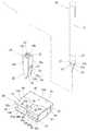
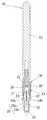
図1は、本発明の第1実施形態に係るナイフセット1を示す。このナイフセット1は、ナイフ10とキャップ18と替え刃ケース(ケース)29とを備える。替え刃ケース29に対してキャップ18をナイフスタンド状態と収納状態の2形態で取付可能とし、使用者の利便性を向上している。
(First embodiment)
FIG. 1 shows a knife set 1 according to a first embodiment of the present invention. Theknife set 1 includes aknife 10, acap 18, and a replacement blade case (case) 29. Thecap 18 can be attached to thereplaceable blade case 29 in two forms, a knife stand state and a stowed state, to improve the convenience for the user.

図1および図2に示すように、ナイフ10は、ペン型ナイフ(デザインナイフ)である。具体的には、ナイフ10は、軸線に直交する断面形状が円形状の軸体11を備える。また、ナイフ10は、軸体11の先端に装着される刃12を備える。軸体11の先端には、刃12を着脱可能に装着するための刃装着部13が形成されている。刃装着部13は、刃12を挟持する一対の挟持部14a,14bと、軸体11のネジ穴部11aに締め付けられるネジ軸部15とを備える。また、挟持部14a,14bと軸体11の下端との間には、円筒状のグリップ16が配設されている。グリップ16の外径は軸体11の外径と同一である。グリップ16の外周部下側には、先端に向けて断面積が小さくなるように縮径した縮径部17が形成される。  As shown in FIGS. 1 and 2, theknife 10 is a pen-type knife (design knife). Specifically, theknife 10 includes ashaft body 11 having a circular cross section perpendicular to the axis. Further, theknife 10 includes ablade 12 attached to the tip of theshaft body 11. Ablade mounting portion 13 for detachably mounting theblade 12 is formed at the tip of theshaft body 11. Theblade mounting portion 13 includes a pair ofsandwiching portions 14 a and 14 b that sandwich theblade 12, and ascrew shaft portion 15 that is fastened to thescrew hole portion 11 a of theshaft body 11. Acylindrical grip 16 is disposed between thesandwiching portions 14 a and 14 b and the lower end of theshaft body 11. The outer diameter of thegrip 16 is the same as the outer diameter of theshaft body 11. On the lower side of the outer peripheral portion of thegrip 16, a reduceddiameter portion 17 having a reduced diameter is formed so that the cross-sectional area decreases toward the tip.

軸体11のネジ穴部11aに対してネジ軸部15を締め付けると、挟持部14a,14bが互いに近づき、これらの挟持部14a,14bに刃12を保持できる。逆に、軸体11のネジ穴部11aに対するネジ軸部15の締め付けを緩めると、挟持部14a,14bが互いに離れ、これら挟持部14a,14bによる刃12の保持が解除される。  When thescrew shaft portion 15 is tightened with respect to thescrew hole portion 11a of theshaft body 11, theholding portions 14a and 14b approach each other, and theblade 12 can be held by theseholding portions 14a and 14b. On the contrary, when thescrew shaft portion 15 is loosely tightened with respect to thescrew hole portion 11a of theshaft body 11, theholding portions 14a and 14b are separated from each other, and the holding of theblade 12 by theholding portions 14a and 14b is released.

図5に最も明瞭に示すように、キャップ18は、非使用時にナイフ10の先端に着脱可能に装着され、刃12を覆う。図1および図3A,Bに示すように、キャップ18を装着したナイフ10が配置面(例えば机の上面)D上で転がるのを防止するために、キャップ18は四角筒状に形成されている。4面の外壁19a〜19dにより、基端に差込口21を有し、先端に閉塞部22を有する四角形状の装着穴部20が画定される。差込口21では、対向する外壁19a,19cおよび外壁19b,19dの内面間の距離が、ナイフ10の軸体11の外径より僅かに大きい。また、装着穴部20内には、外壁19a,19cの中央に圧接リブ23が突設されている。圧接リブ23は、グリップ16の縮径部17を圧接可能な傾斜角度に設定される。この圧接位置まで差し込まれると、ナイフ10とキャップ18とが分離困難な正規装着状態になる。一対の外壁19a,19cの先端側外面に傾斜面24が形成され、キャップ18の先端が三角柱形状に形成されている。なお、圧接リブ23は、外壁19a〜19dの全てに設けてもよい。また、各外壁19a〜19dに形成する圧接リブ23の数、横幅および傾斜角度も希望に応じて変更が可能である。  As most clearly shown in FIG. 5, thecap 18 is detachably attached to the tip of theknife 10 when not in use and covers theblade 12. As shown in FIG. 1 and FIGS. 3A and 3B, in order to prevent theknife 10 fitted with thecap 18 from rolling on the arrangement surface (for example, the upper surface of the desk) D, thecap 18 is formed in a rectangular tube shape. . The fourouter walls 19a to 19d define arectangular mounting hole 20 having aninsertion port 21 at the proximal end and a blockingportion 22 at the distal end. In theinsertion port 21, the distance between the inner surfaces of the opposingouter walls 19 a and 19 c and theouter walls 19 b and 19 d is slightly larger than the outer diameter of theshaft body 11 of theknife 10. Further, in themounting hole portion 20, a press-contact rib 23 projects from the center of theouter walls 19a and 19c. The press-contact rib 23 is set to an inclination angle at which the reduceddiameter portion 17 of thegrip 16 can be press-contacted. When the pressure contact position is inserted, theknife 10 and thecap 18 are in a properly mounted state in which separation is difficult. Aninclined surface 24 is formed on the outer surface on the distal end side of the pair ofouter walls 19a, 19c, and the distal end of thecap 18 is formed in a triangular prism shape. Note that the press-contact ribs 23 may be provided on all of theouter walls 19a to 19d. Moreover, the number of the press-contact ribs 23 formed on each of theouter walls 19a to 19d, the width, and the inclination angle can be changed as desired.

キャップ18には、後述する替え刃ケース29のスタンド用取付部45への取付方向に沿って延びる一対のガイド溝部25,25が形成されている。具体的には、ガイド溝部25,25は、外壁19a,19cの傾斜面24,24に、差込口21へ向けて軸線に沿って平行に延びるように設けられた凹状溝である。個々のガイド溝部25は、外壁19a,19cに対して直交方向に延びる一対の側壁25a,25aと、側壁25a,25a間に延びる底壁25bで画定される。ガイド溝部25の差込口21側の端部には、対向する底壁25b,25bを貫通した矩形状の貫通穴部27が設けられている。なお、貫通穴部27の上縁に前述した圧接リブ23が形成されている。  Thecap 18 is formed with a pair ofguide groove portions 25, 25 that extend along the direction in which thereplaceable blade case 29 described later is attached to thestand attachment portion 45. Specifically, theguide groove portions 25, 25 are concave grooves provided on theinclined surfaces 24, 24 of theouter walls 19 a, 19 c so as to extend parallel to theinsertion port 21 along the axis. Eachguide groove 25 is defined by a pair ofside walls 25a and 25a extending in a direction orthogonal to theouter walls 19a and 19c, and abottom wall 25b extending between theside walls 25a and 25a. At the end of theguide groove portion 25 on theinsertion port 21 side, a rectangular throughhole portion 27 that penetrates the opposedbottom walls 25b, 25b is provided. Note that the above-described press-contact rib 23 is formed on the upper edge of the through-hole portion 27.

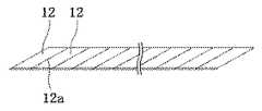
キャップ18には、先端から基端に向けて延びる折刃溝28が設けられている。この折刃溝28は、図3Cに示すカッター刃の刃12を折ってナイフ10に使用するために用いられる。なお、カッター刃は、斜めに延びる複数の切断溝12aを形成することにより、複数の刃12が画定されている。また、薄く扁平なキャップ18の先端は、ヘラとして使用できる。  Thecap 18 is provided with a foldedblade groove 28 extending from the distal end toward the proximal end. Thefolding blade groove 28 is used for folding theblade 12 of the cutter blade shown in FIG. The cutter blade defines a plurality ofblades 12 by forming a plurality of cuttinggrooves 12a extending obliquely. Further, the tip of the thin andflat cap 18 can be used as a spatula.

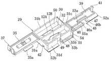
図1および図4A,B,Cに示すように、替え刃ケース29は、上方から見た横寸法Wおよび縦寸法Lが、上面から下面までの高さ寸法Hより大きい矩形状ボックスである。替え刃ケース29は、底壁30から外周壁31a〜31dを立設した上端開口のケースである。これらの壁30,31a〜31dで囲まれた内部空間は、互いに対向する外周壁31a,31cにかけて縦方向Lに延びる隔壁32によって仕切られている。本実施形態では、隔壁32によって仕切られた一方の空間をナイフ10の替え刃(未使用の刃)12Aを収容する第1収容部33とし、他方の空間をナイフ10の使用済み刃12Bを収容する第2収容部34としている。  As shown in FIGS. 1 and 4A, 4B, and 4C, thereplaceable blade case 29 is a rectangular box in which the horizontal dimension W and the vertical dimension L viewed from above are larger than the height dimension H from the upper surface to the lower surface. Thereplacement blade case 29 is a case with an upper end opening in which outerperipheral walls 31 a to 31 d are erected from thebottom wall 30. The internal space surrounded by thesewalls 30, 31a to 31d is partitioned by apartition wall 32 extending in the vertical direction L toward the outerperipheral walls 31a, 31c facing each other. In the present embodiment, one space partitioned by thepartition wall 32 is used as thefirst storage portion 33 for storing the replacement blade (unused blade) 12A of theknife 10, and the other space is used for storing the usedblade 12B of theknife 10. It is set as the 2ndaccommodating part 34 to do.

各収容部33,34の上端開口は、蓋35,39により開放可能に閉塞される。第1収容部33用の第1蓋35は、外周壁31aに薄肉のヒンジ接続部36を介して連結されている。第1蓋35の先端にはロック片37が設けられている。このロック片37を外周壁31cの外側面の突起38に係合することで、第1蓋35で第1収容部33を閉じた状態に保持できる。第2蓋39は、外周壁31cに薄肉のヒンジ接続部40を介して連結されている。第2蓋39の先端には、弾性的に撓む係合片41が設けられている。この係合片41を外周壁31aの内側面からロック孔42に係合することで、第2蓋39で第2収容部34を閉じた状態に保持できる。また、第2蓋39の外面には凹部43が設けられ、この凹部43に使用済み刃12Bを第2収容部34へ挿入する挿入口44が設けられている。さらに、第1蓋35には、第2蓋39の閉塞状態で凹部43に重畳して挿入口44を閉塞する挿入口用蓋部35aが突設されている。  The upper end openings of theaccommodating portions 33 and 34 are closed bylids 35 and 39 so as to be openable. Thefirst lid 35 for the firstaccommodating portion 33 is connected to the outerperipheral wall 31a via a thinhinge connecting portion 36. Alock piece 37 is provided at the tip of thefirst lid 35. By engaging thelock piece 37 with theprotrusion 38 on the outer surface of the outerperipheral wall 31 c, thefirst housing portion 33 can be held closed by thefirst lid 35. Thesecond lid 39 is coupled to the outerperipheral wall 31c via a thinhinge connection portion 40. Anengagement piece 41 that is elastically bent is provided at the tip of thesecond lid 39. By engaging theengagement piece 41 with thelock hole 42 from the inner side surface of the outerperipheral wall 31a, thesecond housing portion 34 can be held closed by thesecond lid 39. Further, aconcave portion 43 is provided on the outer surface of thesecond lid 39, and aninsertion port 44 through which the usedblade 12 </ b> B is inserted into the secondaccommodating portion 34 is provided in theconcave portion 43. Further, thefirst lid 35 is provided with an insertionport lid portion 35 a that protrudes from thefirst lid 35 so as to overlap theconcave portion 43 when thesecond lid 39 is closed.

替え刃ケース29には、第2収容部34の外周部である外周壁31dの中央に位置するように、スタンド用取付部(第1の取付部)45が設けられている。このスタンド用取付部45は、キャップ18を取り付けると、図8および図9に示すように、上面である第2蓋39から上方にキャップ18の差込口21側を突出させるとともに、下面である底壁30から下方にキャップ18の閉塞部22側を突出させることができる。  Thereplaceable blade case 29 is provided with a stand attachment portion (first attachment portion) 45 so as to be positioned at the center of the outerperipheral wall 31d which is the outer peripheral portion of thesecond housing portion 34. 8 and 9, when thecap 18 is attached, thestand attachment portion 45 projects theinsertion port 21 side of thecap 18 upward from thesecond lid 39, which is the upper surface, and is the lower surface. The closingportion 22 side of thecap 18 can be protruded downward from thebottom wall 30.

具体的には、スタンド用取付部45は、図1に示すように、上面である第2蓋39から下面である底壁30にかけて貫通する第1および第2挿通部46a,46bを有する孔状である。第1挿通部46aは、一対のガイド溝25,25の側壁25a,25aの部分を挿通可能な孔幅である。第2挿通部46bは、第1挿通部46aに連通し、第1挿通部46aより小さい孔幅であり、一対のガイド溝部25,25の底壁25b,25bの部分を挿通する。また、第2挿通部46bは、第1挿通部46aから側縁にかけて幅方向Wに延びて開放されている。  Specifically, as shown in FIG. 1, thestand attachment portion 45 has a hole shape having first andsecond insertion portions 46 a and 46 b that penetrate from thesecond lid 39 that is the upper surface to thebottom wall 30 that is the lower surface. It is. Thefirst insertion portion 46a has a hole width through which theside walls 25a and 25a of the pair ofguide grooves 25 and 25 can be inserted. Thesecond insertion part 46b communicates with thefirst insertion part 46a, has a smaller hole width than thefirst insertion part 46a, and passes through thebottom walls 25b, 25b of the pair ofguide groove parts 25, 25. Thesecond insertion portion 46b extends in the width direction W from thefirst insertion portion 46a to the side edge and is opened.

スタンド用取付部45には、第2挿通部46bの両側にキャップ18のガイド溝部25に嵌まるガイド突部47が形成される。ガイド突部47は、後述する収納用取付部51の保持枠52a,53aの端部により構成される。ガイド突部47の先端は、キャップ18の取付時にガイド溝部25の底壁25bに摺接し、キャップ18の取付状態で貫通穴部27を通してキャップ18内に位置する。これによりガイド突部47は、差込口21からキャップ18内に差し込んだナイフ10に干渉し、ナイフ10がキャップ18の装着位置まで差し込まれることを阻止する干渉部を構成する。  Guide protrusions 47 that fit into theguide groove portions 25 of thecap 18 are formed on the both sides of thesecond insertion portion 46b. Theguide protrusion 47 is constituted by end portions of holdingframes 52a and 53a of astorage mounting portion 51 described later. The distal end of theguide protrusion 47 is in sliding contact with thebottom wall 25b of theguide groove 25 when thecap 18 is attached, and is positioned in thecap 18 through the throughhole 27 when thecap 18 is attached. Thereby, theguide protrusion 47 constitutes an interference portion that interferes with theknife 10 inserted into thecap 18 from theinsertion port 21 and prevents theknife 10 from being inserted to the mounting position of thecap 18.

外周壁31dは、第1挿通部46aの縁に沿って立設される枠壁48を備える。この枠壁48により第2収容部34内と第1挿通部46a内とが仕切られている。また、第1挿通部46aの下端には、キャップ18が逆向きに装着されることを防止するために、底壁30に沿って延びる誤装着防止リブ49が設けられている。  The outerperipheral wall 31d includes aframe wall 48 standing along the edge of thefirst insertion portion 46a. Theframe wall 48 partitions thesecond housing portion 34 and thefirst insertion portion 46a. Further, an erroneousattachment preventing rib 49 extending along thebottom wall 30 is provided at the lower end of thefirst insertion portion 46a in order to prevent thecap 18 from being attached in the reverse direction.

本実施形態のスタンド用取付部45は、キャップ18の先端を替え刃ケース29の下面から突出させた状態で、キャップ18を取り付ける。これにより、図9に示すように、キャップ18の先端と替え刃ケース29の外周壁31bの下端縁とを配置面D上に配置して、キャップ18を傾斜させて配置可能としている。本実施形態では、ナイフスタンド状態での安定性を高めるために、スタンド用取付部45の反対側に位置する外周壁31bの下端縁に、角部を面取りした平面状の支持部50が設けられている。支持部50は、配置面Dと平行に延びて面接触する角度で形成されている。  Thestand attachment portion 45 of this embodiment attaches thecap 18 with the tip of thecap 18 protruding from the lower surface of thereplaceable blade case 29. As a result, as shown in FIG. 9, the tip of thecap 18 and the lower end edge of the outerperipheral wall 31b of thereplaceable blade case 29 are arranged on the arrangement surface D, and thecap 18 can be arranged in an inclined state. In the present embodiment, in order to increase the stability in the knife stand state, aplanar support portion 50 with a chamfered corner is provided at the lower end edge of the outerperipheral wall 31b located on the opposite side of thestand attachment portion 45. ing. Thesupport portion 50 is formed at an angle that extends parallel to the arrangement surface D and makes surface contact.

配置面Dに対するキャップ18の傾斜角度αは、ナイフ10をキャップ18に装着した状態で転倒することなく、安定したスタンド状態を維持できる範囲で設定される。具体的には、キャップ18に装着したナイフ10の重心Gが、配置面D上に配置したキャップ18の先端と、替え刃ケース29の支持部50の外端との間の支持範囲S内に位置するように、キャップ18の傾斜角度αを設定する。言い換えれば、ナイフ10の重心Gが支持範囲S内に位置するように、替え刃ケース29の下面からのキャップ18の先端の突出寸法、および、替え刃ケース29の幅寸法Wを設定する。なお、ナイフ10の重心Gは、支持範囲Sの中央付近に設定することが好ましい。また、本実施形態のキャップ18の傾斜角度αは60度である。  The inclination angle α of thecap 18 with respect to the arrangement surface D is set within a range in which a stable stand state can be maintained without falling down while theknife 10 is mounted on thecap 18. Specifically, the center of gravity G of theknife 10 attached to thecap 18 is within the support range S between the tip of thecap 18 arranged on the arrangement surface D and the outer end of thesupport portion 50 of thereplaceable blade case 29. The inclination angle α of thecap 18 is set so as to be positioned. In other words, the protruding dimension of the tip of thecap 18 from the lower surface of thereplaceable blade case 29 and the width dimension W of thereplaceable blade case 29 are set so that the center of gravity G of theknife 10 is located within the support range S. The center of gravity G of theknife 10 is preferably set near the center of the support range S. Further, the inclination angle α of thecap 18 of the present embodiment is 60 degrees.

替え刃ケース29には、第2収容部34の外周部である外周壁31dに収納用取付部(第2の取付部)51が更に設けられている。図6に示すように、収納用取付部51は、キャップ18の差込口21を有する基端から閉塞部22を有する先端にかけたキャップ18全体を、替え刃ケース29の上面から下面の間に位置するように取り付ける。収納用取付部51へのキャップ18の取付方向は、スタンド用取付部45への取付方向と直交する方向である。  Thereplaceable blade case 29 is further provided with a storage attachment portion (second attachment portion) 51 on an outerperipheral wall 31 d that is an outer peripheral portion of thesecond storage portion 34. As shown in FIG. 6, thestorage mounting portion 51 is configured such that theentire cap 18 that is applied from the proximal end having theinsertion port 21 of thecap 18 to the distal end having the closingportion 22 is interposed between the upper surface and the lower surface of thereplaceable blade case 29. Install so that it is positioned. The attachment direction of thecap 18 to thestorage attachment portion 51 is a direction orthogonal to the attachment direction to thestand attachment portion 45.

具体的には、図1に示すように、替え刃ケース29の上面である第2蓋39および下面である底壁30から外向きに突出する保持枠52a,52b,53a,53bを備える。第1保持枠52a,52bはスタンド用取付部45の左側から突設され、第2保持枠53a,53bはスタンド用取付部45の右側から突設される。第1保持枠52a,52bと第2保持枠53a,53bの間の隙間が、第2挿通部46bを構成する。第2保持枠53a,53bには、右側端部を閉塞するリブ54が形成されている。また、第2保持枠53a,53bには、キャップ18のガイド溝部25の側壁25aに係合するガイド壁部55a,55bが突設されている。  Specifically, as shown in FIG. 1, holdingframes 52 a, 52 b, 53 a, and 53 b that protrude outward from thesecond lid 39 that is the upper surface of thereplaceable blade case 29 and thebottom wall 30 that is the lower surface are provided. The first holding frames 52 a and 52 b protrude from the left side of thestand attachment portion 45, and the second holding frames 53 a and 53 b protrude from the right side of thestand attachment portion 45. The gap between the first holdingframes 52a and 52b and the second holding frames 53a and 53b constitutes thesecond insertion portion 46b. The second holding frames 53a and 53b are formed withribs 54 that close the right end. In addition,guide wall portions 55 a and 55 b that engage with theside walls 25 a of theguide groove portion 25 of thecap 18 protrude from the second holding frames 53 a and 53 b.

次に、本実施形態のナイフセット1の使用方法について説明する。なお、ナイフ10、キャップ18および替え刃ケース29は、1組に纏めてセット販売する場合と、ナイフ10とキャップ18とはセット販売して替え刃ケース29は別売りする場合とがある。  Next, the usage method of the knife set 1 of this embodiment is demonstrated. Theknife 10, thecap 18 and thereplacement blade case 29 may be sold together as a set, or theknife 10 and thecap 18 may be sold as a set and thereplacement blade case 29 sold separately.

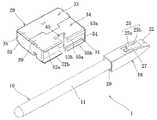
図5に示すように、ナイフ10を使用しない時には、ナイフ10の先端にキャップ18を装着し、刃12を覆う。図6に示すように、先端が開放された収納用取付部51の第1保持枠52a,52bの間にキャップ18を配置する。そして、キャップ18の先端から第2保持枠53a,53b間へ差し込み、側壁25aをガイド壁部55a,55bに係合させる。これにより、ナイフ10とキャップ18と替え刃ケース29とからなるナイフセット1を一体的に纏めることができる。よって、保管時に一部の部品が紛失することを防止できる。また、この収納状態は、キャップ18の先端および基端が替え刃ケース29の上下面間に位置するように取り付けられる構成である。よって、全ての部品が横方向に延びるコンパクトな収納状態を実現できる。  As shown in FIG. 5, when theknife 10 is not used, acap 18 is attached to the tip of theknife 10 to cover theblade 12. As shown in FIG. 6, thecap 18 is disposed between the first holding frames 52 a and 52 b of thestorage attachment portion 51 whose tip is opened. And it inserts between the 2nd holdingframes 53a and 53b from the front-end | tip of thecap 18, and theside wall 25a is engaged with theguide wall parts 55a and 55b. Thereby, the knife set 1 which consists of theknife 10, thecap 18, and thereplaceable blade case 29 can be gathered together. Therefore, it is possible to prevent some parts from being lost during storage. Further, this stored state is a configuration in which the tip and the base end of thecap 18 are attached so as to be positioned between the upper and lower surfaces of thereplaceable blade case 29. Therefore, a compact storage state in which all components extend in the lateral direction can be realized.

ナイフ10を使用する時には、替え刃ケース29の収納用取付部51からキャップ18と一緒にナイフ10を取り外す。ついで、ナイフ10からキャップ18を取り外した後、図7に示すように、キャップ18をスタンド用取付部45に取り付ける。具体的には、キャップ18を先端からスタンド用取付部45に挿入し、ガイド溝部25内にガイド突部47を位置させる。そして、ガイド突部47がガイド溝部25の端に位置するまで、替え刃ケース29にキャップ18を差し込む。  When using theknife 10, theknife 10 is removed together with thecap 18 from thestorage mounting portion 51 of thereplaceable blade case 29. Next, after removing thecap 18 from theknife 10, thecap 18 is attached to thestand attachment portion 45 as shown in FIG. 7. Specifically, thecap 18 is inserted into thestand mounting portion 45 from the tip, and theguide protrusion 47 is positioned in theguide groove portion 25. Then, thecap 18 is inserted into thereplaceable blade case 29 until theguide protrusion 47 is positioned at the end of theguide groove 25.

これにより、キャップ18の差込口21を有する基端が替え刃ケース29の上面の上方に位置するナイフスタンド状態とすることができる。このナイフスタンド状態では、キャップ18の閉塞部22を有する先端が替え刃ケース29の下面から突出し、配置面D上に置くとキャップ18が傾斜した状態となっている。  Thereby, it can be set as the knife stand state in which the base end which has theinsertion port 21 of thecap 18 is located above the upper surface of thereplaceable blade case 29. FIG. In this knife stand state, the tip of thecap 18 having the closingportion 22 protrudes from the lower surface of thereplaceable blade case 29, and when placed on the arrangement surface D, thecap 18 is inclined.

ナイフ10の使用を中断する時には、ナイフ10を差込口21からキャップ18に差し込むことで、図8および図9に示すように、ナイフ10を立てた状態で置くことができる。この際、キャップ18の装着穴部20内には、貫通穴部27を通してスタンド用取付部45のガイド突部47が突出している。そのため、図10および図11Aに示すように、ナイフ10は、挟持部14a,14bの外周面に替え刃ケース29の干渉部であるガイド突部47が当接(干渉)すると、それ以上の差し込みが阻止される。この状態では、ナイフ10の縮径部17がキャップ18の圧接リブ23に圧接されていない(非正規装着状態)。よって、ナイフ10を再び使用する際に、ナイフ10だけを簡単に取り外すことができる。なお、正規装着位置は、図11Bに示すように、ナイフ10の縮径部17がキャップ18の圧接リブ23に圧接されるまで差し込んだ状態である。  When the use of theknife 10 is interrupted, theknife 10 can be placed in an upright state as shown in FIGS. 8 and 9 by inserting theknife 10 into thecap 18 through theinsertion port 21. At this time, aguide protrusion 47 of thestand attachment portion 45 protrudes through the throughhole portion 27 into the mountinghole portion 20 of thecap 18. Therefore, as shown in FIG. 10 and FIG. 11A, when theguide protrusion 47, which is the interference part of thereplacement blade case 29, abuts (interferes) with the outer peripheral surface of theclamping parts 14a and 14b, theknife 10 is inserted further. Is blocked. In this state, the reduceddiameter portion 17 of theknife 10 is not in pressure contact with thepressure contact rib 23 of the cap 18 (non-regular wearing state). Therefore, when theknife 10 is used again, only theknife 10 can be easily removed. The normal mounting position is a state where the reduceddiameter portion 17 of theknife 10 is inserted until it is pressed against the press-contact rib 23 of thecap 18, as shown in FIG. 11B.

このように、本実施形態のナイフセット1は、ナイフ10を使用する際には、キャップ18を替え刃ケース29に取り付けることにより、ナイフスタンドとすることができる。よって、ナイフ10の使用時にキャップ18が紛失することを防止できる。しかも、ナイフ10の使用を中断する際には、ナイフスタンドとしたキャップ18に差し込むことで、ナイフ10を立てた状態で置くことができる。よって、ナイフ10が転がって机から落下することを確実に防止できる。  Thus, when using theknife 10, the knife set 1 of this embodiment can be used as a knife stand by attaching thecap 18 to thereplaceable blade case 29. Therefore, it is possible to prevent thecap 18 from being lost when theknife 10 is used. Moreover, when the use of theknife 10 is interrupted, theknife 10 can be placed in an upright state by being inserted into thecap 18 serving as a knife stand. Therefore, it can prevent reliably that theknife 10 rolls and falls from a desk.

また、ナイフスタンド状態では、キャップ18が傾斜しているうえ、キャップ18に対してナイフ10を正規装着位置まで装着できないようにしている。よって、キャップ18に対するナイフ10の取り付けおよび取り外しが容易であり、使用者の利便性を大幅に向上できる。さらに、キャップ18に装着したナイフ10の重心が、配置面Dの支持範囲S内に位置するように、キャップ18の傾斜角度αを設定しているため、安定状態でナイフ10を立てることができる。  Further, in the knife stand state, thecap 18 is inclined and theknife 10 cannot be mounted on thecap 18 to the regular mounting position. Therefore, attachment and removal of theknife 10 with respect to thecap 18 are easy, and a user's convenience can be improved significantly. Furthermore, since the inclination angle α of thecap 18 is set so that the center of gravity of theknife 10 attached to thecap 18 is located within the support range S of the arrangement surface D, theknife 10 can be stood in a stable state. .

このように、ナイフセット1は、ナイフ10の関連商品である替え刃ケース29に対してキャップ18を2通りの状態で取付可能としているため、ナイフ10の使用時および非使用時のいずれでも、キャップ18が紛失することを確実に防止できる。また、取付部45,51へのキャップ18の取り付けは、ガイド溝部25にガイド突部47またはガイド壁部55a,55bを嵌合させるように、キャップ18を先端から差し込むだけで良いため、作業性を向上できる。  As described above, the knife set 1 can attach thecap 18 to thereplaceable blade case 29 that is a related product of theknife 10 in two states. It is possible to reliably prevent thecap 18 from being lost. Further, since thecap 18 can be attached to theattachment portions 45 and 51 only by inserting thecap 18 from the tip so that theguide protrusion 47 or theguide wall portions 55a and 55b are fitted into theguide groove portion 25, workability is improved. Can be improved.

(第2実施形態)
図12および図13は第2実施形態のナイフセット1を示す。このナイフセット1は、スタンド用取付部45を簡素化するとともに、収納用取付部51を設けていない点で、第1実施形態と相違する。
(Second Embodiment)
12 and 13 show the knife set 1 of the second embodiment. The knife set 1 is different from the first embodiment in that thestand attachment portion 45 is simplified and thestorage attachment portion 51 is not provided.

具体的には、キャップ18の外壁19a,19cには、傾斜面24を除く位置に円形状の孔からなる取付穴56が設けられている。替え刃ケース29は、一端を開口したケース本体57と、ケース本体57の開口を閉塞するスライド蓋58とを備える。ケース本体57の内部には替え刃12Aが収納され、使用済み刃12Bの収容部は設けられていない。また、本体ケースの開口は、スライド蓋58のスライドにより開閉可能である。そして、ケース本体57には、スタンド用取付部45として、開口と逆側の閉鎖端に、キャップ18の取付穴56に取付可能な円柱状取付部59が突設されている。  Specifically, theouter walls 19 a and 19 c of thecap 18 are provided with mountingholes 56 formed of circular holes at positions excluding theinclined surface 24. Thereplaceable blade case 29 includes a casemain body 57 that is open at one end, and aslide lid 58 that closes the opening of the casemain body 57. Thereplacement blade 12A is housed inside thecase body 57, and the housing portion for the usedblade 12B is not provided. Further, the opening of the main body case can be opened and closed by sliding theslide lid 58. The casemain body 57 is provided with acolumnar attachment portion 59 that can be attached to theattachment hole 56 of thecap 18 at the closed end opposite to the opening as thestand attachment portion 45.

この第2実施形態のナイフセット1は、第1実施形態と同様に、ナイフ10から取り外したキャップ18を替え刃ケース29に取り付けることにより、ナイフスタンドを形成することができる。そのため、ナイフ10の使用時にキャップ18が紛失することを防止できるとともに、使用中断時にナイフ10が転がって机から落下することを確実に防止できる。  As in the first embodiment, the knife set 1 of the second embodiment can form a knife stand by attaching thecap 18 removed from theknife 10 to thereplaceable blade case 29. Therefore, it is possible to prevent thecap 18 from being lost when theknife 10 is used, and to reliably prevent theknife 10 from rolling and dropping from the desk when use is interrupted.

(第3実施形態)
図14および図15は第3実施形態のナイフセット1を示す。このナイフセット1は、スタンド用取付部45を替え刃ケース29の中央付近に設けた点で、各実施形態と相違する。スタンド用取付部45は、一対の第1挿通部46a,46aと、これらに連通するように設けた第2挿通部46bを備える。このようにした第3実施形態は、替え刃ケース29の上面からスタンド用取付部45にキャップ18を差し込むことにより、第1実施形態と同様の作用および効果を得ることができる。
(Third embodiment)
14 and 15 show the knife set 1 of the third embodiment. This knife set 1 is different from each embodiment in that astand attachment portion 45 is provided near the center of thereplaceable blade case 29. Thestand attachment portion 45 includes a pair offirst insertion portions 46a and 46a and asecond insertion portion 46b provided so as to communicate therewith. The third embodiment thus configured can obtain the same operations and effects as those of the first embodiment by inserting thecap 18 into thestand attachment portion 45 from the upper surface of thereplacement blade case 29.

(第4実施形態)
図16は第4実施形態のナイフセット1を示す。このナイフセット1は、スタンド用取付部45を替え刃ケース29の中央に設けるとともに、貫通させて取り付けたキャップ18の軸線が垂直方向に延びるように配置可能とした点で、各実施形態と相違する。具体的には、替え刃ケース29は、貫通したキャップ18の先端と一緒に配置面Dに載置する支持脚部60を備えている。支持脚部60は、替え刃ケース29に対して図示の突出状態から底壁30に平行に位置する状態にかけて、回動可能とすることが好ましい。このようにした第4実施形態では、替え刃ケース29の上面からスタンド用取付部45にキャップ18を差し込むことにより、第1実施形態と同様の作用および効果を得ることができる。
(Fourth embodiment)
FIG. 16 shows a knife set 1 of the fourth embodiment. This knife set 1 is different from each embodiment in that astand attachment portion 45 is provided in the center of thereplaceable blade case 29 and can be arranged so that the axis of thecap 18 attached to penetrate through extends vertically. To do. Specifically, thereplaceable blade case 29 includes asupport leg 60 that is placed on the arrangement surface D together with the tip of the penetratingcap 18. Thesupport leg 60 is preferably rotatable with respect to thereplaceable blade case 29 from the illustrated protruding state to a state positioned parallel to thebottom wall 30. In the fourth embodiment thus configured, by inserting thecap 18 from the upper surface of thereplacement blade case 29 into thestand attachment portion 45, the same operation and effect as in the first embodiment can be obtained.

なお、本発明のナイフセット1は、前記実施形態に限定されず、種々の変更が可能である。  In addition, the knife set 1 of this invention is not limited to the said embodiment, A various change is possible.

例えば、ケース29は、第1実施形態では未使用の替え刃12Aと使用済み刃12Bの両方を収容可能とし、第2実施形態では替え刃12Aのみを収容可能としたが、使用済み刃12Bのみを収容可能としてもよい。また、刃12以外を収容するケース12にスタンド用取付部45を設ける構成としてもよい。  For example, thecase 29 can accommodate both theunused replacement blade 12A and the usedblade 12B in the first embodiment, and can accommodate only thereplacement blade 12A in the second embodiment, but only the usedblade 12B. Can be accommodated. Moreover, it is good also as a structure which provides the attachingpart 45 for stands in thecase 12 which accommodates except theblade 12. FIG.

さらに、前記各実施形態では、ケース29の下面からキャップ18の先端を突出させる構成としたが、キャップ18の先端が突出しない構成としてもよい。さらにまた、前記各実施形態では、刃12を着脱可能としたナイフ10を用いたが、刃12は着脱不可能な固定式であってもよいうえ、刃12を着脱可能とする構成も前記形態に限定されない。  Furthermore, in each said embodiment, although it was set as the structure which protrudes the front-end | tip of thecap 18 from the lower surface of thecase 29, it is good also as a structure which the front-end | tip of thecap 18 does not protrude. Furthermore, in each of the above embodiments, theknife 10 in which theblade 12 is detachable is used. However, theblade 12 may be a fixed type that is not detachable, and the configuration in which theblade 12 is detachable is also in the above form. It is not limited to.

そして、ナイフスタンドとした状態で、ナイフ10をキャップ18の正規装着位置まで装着できなくする構成も種々の変更が可能である。特に、前記実施形態では、スタンド用取付部45の干渉部であるガイド突部47および円柱状取付部59は、ナイフ10の挟持部14a,14bの外周面に干渉する構成としたが、刃装着部13の先端面に干渉する構成としてもよく、ナイフ10の構造に応じて変更することが好ましい。  The configuration in which theknife 10 cannot be mounted to the normal mounting position of thecap 18 in the state of the knife stand can be variously changed. In particular, in the above-described embodiment, theguide protrusion 47 and thecolumnar attachment portion 59 that are the interference portions of thestand attachment portion 45 are configured to interfere with the outer peripheral surfaces of the sandwichingportions 14a and 14b of theknife 10. It is good also as a structure which interferes in the front end surface of thepart 13, and changing according to the structure of theknife 10 is preferable.

1…ナイフセット
10…ナイフ
11…軸体
12…刃
12A…替え刃
12B…使用済み刃
13…刃装着部
18…キャップ
21…差込口
22…閉塞部
25…ガイド溝部
27…貫通穴部
29…替え刃ケース
33…第1収容部(替え刃収容部)
34…第2収容部(使用済み刃収容部)
45…スタンド用取付部(第1の取付部)
46a…第1挿通部
47…ガイド突部(干渉部)
50…支持部
51…収納用取付部(第2の取付部)
52a,52b…第1保持枠
53a,53b…第2保持枠
55a,55b…ガイド壁部
D…配置面(机)
DESCRIPTION OFSYMBOLS 1 ... Knife set 10 ...Knife 11 ...Shaft body 12 ...Blade 12A ...Replacement blade 12B ...Used blade 13 ...Blade mounting part 18 ...Cap 21 ...Insertion port 22 ...Closure part 25 ...Guide groove part 27 ... Through-hole part 29 ...Replacement blade case 33 ... 1st accommodating part (replacement blade accommodating part)
34 ... 2nd accommodating part (used blade accommodating part)
45 ... Stand mounting part (first mounting part)
46a ...1st insertion part 47 ... Guide protrusion (interference part)
50: Supporting part 51: Storage mounting part (second mounting part)
52a, 52b ...1st holding frame 53a, 53b ...2nd holding frame 55a, 55b ... Guide wall part D ... Arrangement surface (desk)

Claims (16)

Translated fromJapanese
軸体と、前記軸体の先端に装着された刃とを有するナイフと、
前記軸体の先端に着脱可能に装着され、前記ナイフの前記刃を覆うキャップと、
前記キャップの差込口を有する基端が上方に位置するように前記キャップを着脱可能に取り付ける第1の取付部を有するケースと、
を備え
前記ナイフの前記刃は、前記軸体の先端に着脱可能に装着され、前記ケースは、未使用または使用済みの前記刃を収容する収容部を有することを特徴とするナイフセット。
A knife having a shaft and a blade attached to the tip of the shaft;
A cap that is detachably attached to the tip of the shaft body and covers the blade of the knife;
A case having a first attachment portion for detachably attaching the cap so that a base end having the insertion port of the cap is positioned above;
Equipped witha,
The knife set is characterized in that theblade of the knife is detachably attached to the tip of the shaft body, and the case has an accommodating portion for accommodating the unused or used blade .
前記第1の取付部は、前記キャップの先端が前記ケースの下面より下方に位置するように前記キャップを取付可能であることを特徴とする請求項1に記載のナイフセット。2. The knife set according toclaim 1, wherein the first mounting portion is capable of mounting the cap such that a tip of the cap is positioned below a lower surface of the case. 軸体と、前記軸体の先端に装着された刃とを有するナイフと、
前記軸体の先端に着脱可能に装着され、前記ナイフの前記刃を覆うキャップと、
前記キャップの差込口を有する基端が上方に位置するように前記キャップを着脱可能に取り付ける第1の取付部を有するケースと、
を備え
前記第1の取付部は、前記キャップの先端が前記ケースの下面より下方に位置するように前記キャップを取付可能であることを特徴とするナイフセット。
A knife having a shaft and a blade attached to the tip of the shaft;
A cap that is detachably attached to the tip of the shaft body and covers the blade of the knife;
A case having a first attachment portion for detachably attaching the cap so that a base end having the insertion port of the cap is positioned above;
Equipped witha,
The knife set according toclaim 1, wherein the first attachment portion is capable of attaching the cap such that a tip of the cap is positioned below a lower surface of the case .
前記キャップの取付状態で、前記キャップの先端と前記ケースの下面の支持部とを配置面上に配置し、前記キャップを傾斜させて配置可能としたことを特徴とする請求項2または請求項3に記載のナイフセット。4. The cap according toclaim 2 , wherein a tip of the cap and a support portion of the lower surface of the case are arranged on a placement surface in the attached state of the cap, and the cap can be inclined and arranged. knife set accordingto. 前記キャップの傾斜角度は、前記キャップに装着した前記ナイフの重心が、前記キャップの先端と前記ケースの支持部との間に位置するように設定されることを特徴とする請求項4に記載のナイフセット。The inclination angle of the cap is set so that the center of gravity of the knife attached to the cap is positioned between the tip of the cap and the support portion of thecase . Knife set. 前記第1の取付部は、前記ケースの上面から下面に向けて貫通した孔状であることを特徴とする請求項1乃至請求項5のいずれか1項に記載のナイフセット。  The knife set according to any one of claims 1 to 5, wherein the first attachment portion has a hole shape penetrating from the upper surface to the lower surface of the case. 前記第1の取付部は、前記キャップの取付方向に直交する方向に延びる第1挿通部と、前記第1挿通部に連通し前記第1挿通部より幅が小さい第2挿通部とを有し、前記第2挿通部の両側にガイド突部が形成されていることを特徴とする請求項6に記載のナイフセット。  The first attachment portion includes a first insertion portion that extends in a direction orthogonal to the attachment direction of the cap, and a second insertion portion that communicates with the first insertion portion and has a smaller width than the first insertion portion. The knife set according to claim 6, wherein guide protrusions are formed on both sides of the second insertion portion. 前記キャップは、前記ケースの前記第1の取付部への取付方向に沿って延び、前記ガイド突部が嵌合するガイド溝部を有することを特徴とする請求項7に記載のナイフセット。  The knife set according to claim 7, wherein the cap has a guide groove portion that extends along a direction in which the case is attached to the first attachment portion, and into which the guide protrusion is fitted. 前記第1の取付部は、前記キャップの取付状態で前記キャップ内に位置し、前記差込口から前記キャップ内に差し込んだ前記ナイフに干渉して、前記ナイフが前記キャップの装着位置まで差し込まれることを阻止する干渉部を有することを特徴とする請求項1乃至請求項8のいずれか1項に記載のナイフセット。  The first attachment portion is located in the cap in the attached state of the cap, interferes with the knife inserted into the cap from the insertion port, and the knife is inserted to the mounting position of the cap. The knife set according to any one of claims 1 to 8, further comprising an interference unit that prevents the interference. 軸体と、前記軸体の先端に装着された刃とを有するナイフと、
前記軸体の先端に着脱可能に装着され、前記ナイフの前記刃を覆うキャップと、
前記キャップの差込口を有する基端が上方に位置するように前記キャップを着脱可能に取り付ける第1の取付部を有するケースと、
を備え
前記第1の取付部は、前記キャップの取付状態で前記キャップ内に位置し、前記差込口から前記キャップ内に差し込んだ前記ナイフに干渉して、前記ナイフが前記キャップの装着位置まで差し込まれることを阻止する干渉部を有することを特徴とするナイフセット。
A knife having a shaft and a blade attached to the tip of the shaft;
A cap that is detachably attached to the tip of the shaft body and covers the blade of the knife;
A case having a first attachment portion for detachably attaching the cap so that a base end having the insertion port of the cap is positioned above;
Equipped witha,
The first attachment portion is located in the cap in the attached state of the cap, interferes with the knife inserted into the cap from the insertion port, and the knife is inserted to the mounting position of the cap. A knife setcomprising an interference portion for preventing the interference .
前記ケースに、前記第1の取付部への前記キャップの取付方向に直交する方向を取付方向とした第2の取付部を設けたことを特徴とする請求項1乃至請求項10のいずれか1項に記載のナイフセット。In the case, any oneof claims 1 to10, characterized in that the direction orthogonal to the mounting direction of the first of the cap to the mounting portion provided with a second attachment portion and a mounting direction 1 The knife set as described in the item. 軸体と、前記軸体の先端に装着された刃とを有するナイフと、
前記軸体の先端に着脱可能に装着され、前記ナイフの前記刃を覆うキャップと、
前記キャップの差込口を有する基端が上方に位置するように前記キャップを着脱可能に取り付ける第1の取付部を有するケースと、
を備え
前記ケースに、前記第1の取付部への前記キャップの取付方向に直交する方向を取付方向とした第2の取付部を設けたことを特徴とするナイフセット。
A knife having a shaft and a blade attached to the tip of the shaft;
A cap that is detachably attached to the tip of the shaft body and covers the blade of the knife;
A case having a first attachment portion for detachably attaching the cap so that a base end having the insertion port of the cap is positioned above;
Equipped witha,
The knife set characterizedby providing the said case withthe 2nd attachment part which made the attachment direction the direction orthogonal to the attachment direction of the said cap to the said 1st attachment part .
軸体と、前記軸体の先端に装着された刃とを有し、前記軸体の先端に前記刃を覆うキャップを装着するナイフ用のケースであって、
前記キャップの差込口を有する基端が上方に位置するように前記キャップを着脱可能に取り付ける第1の取付部を設けるとともに、
前記軸体の先端に着脱可能に装着される前記ナイフの未使用または使用済みの前記刃を収容する収容部を設けた
ことを特徴とするナイフ用のケース。
A case for a knife having a shaft body and a blade attached to the tip of the shaft body, and attaching a cap covering the blade to the tip of the shaft body,
Base end having an insertion portalong with Keru set the first mounting portion removably attaching the cap to be located above thecap,
An accommodation portion is provided for accommodating the unused or used blade of the knife that is detachably attached to the tip of the shaft body.
Case for knives characterized by that.
軸体と、前記軸体の先端に装着された刃とを有し、前記軸体の先端に前記刃を覆うキャップを装着するナイフ用のケースであって、
前記キャップの差込口を有する基端が上方に位置するように前記キャップを着脱可能に取り付ける第1の取付部を設けるとともに、
前記第1の取付部を、前記キャップの先端が下面より下方に位置するように前記キャップを取付可能に形成した
ことを特徴とするナイフ用のケース。
A case for a knife having a shaft body and a blade attached to the tip of the shaft body, and attaching a cap covering the blade to the tip of the shaft body,
Base end having an insertion portalong with Keru set the first mounting portion removably attaching the cap to be located above thecap,
The first mounting portion is formed so that the cap can be mounted so that the tip of the cap is positioned below the lower surface.
Case for knives characterized by that.
軸体と、前記軸体の先端に装着された刃とを有し、前記軸体の先端に前記刃を覆うキャップを装着するナイフ用のケースであって、
前記キャップの差込口を有する基端が上方に位置するように前記キャップを着脱可能に取り付ける第1の取付部を設けるとともに、
前記第1の取付部に、前記キャップの取付状態で前記キャップ内に位置し、前記差込口から前記キャップ内に差し込んだ前記ナイフに干渉して、前記ナイフが前記キャップの装着位置まで差し込まれることを阻止する干渉部を設けた
ことを特徴とするナイフ用のケース。
A case for a knife having a shaft body and a blade attached to the tip of the shaft body, and attaching a cap covering the blade to the tip of the shaft body,
Base end having an insertion portalong with Keru set the first mounting portion removably attaching the cap to be located above thecap,
The first attachment portion is located in the cap in the attached state of the cap, interferes with the knife inserted into the cap from the insertion port, and the knife is inserted to the mounting position of the cap. An interference unit was installed to prevent this.
Case for knives characterized by that.
軸体と、前記軸体の先端に装着された刃とを有し、前記軸体の先端に前記刃を覆うキャップを装着するナイフ用のケースであって、
前記キャップの差込口を有する基端が上方に位置するように前記キャップを着脱可能に取り付ける第1の取付部を設けるとともに、
前記第1の取付部への前記キャップの取付方向に直交する方向を取付方向とした第2の取付部を設けた
ことを特徴とするナイフ用のケース。
A case for a knife having a shaft body and a blade attached to the tip of the shaft body, and attaching a cap covering the blade to the tip of the shaft body,
Base end having an insertion portalong with Keru set the first mounting portion removably attaching the cap to be located above thecap,
A second mounting portion having a mounting direction as a direction orthogonal to the mounting direction of the cap to the first mounting portion is provided.
Case for knives characterized by that.
JP2013098627A2013-05-082013-05-08 Knife set and knife caseActiveJP5597280B1 (en)

Priority Applications (1)

Application NumberPriority DateFiling DateTitle
JP2013098627AJP5597280B1 (en)2013-05-082013-05-08 Knife set and knife case

Applications Claiming Priority (1)

Application NumberPriority DateFiling DateTitle
JP2013098627AJP5597280B1 (en)2013-05-082013-05-08 Knife set and knife case

Publications (2)

Publication NumberPublication Date
JP5597280B1true JP5597280B1 (en)2014-10-01
JP2014217565A JP2014217565A (en)2014-11-20

Family

ID=51840263

Family Applications (1)

Application NumberTitlePriority DateFiling Date
JP2013098627AActiveJP5597280B1 (en)2013-05-082013-05-08 Knife set and knife case

Country Status (1)

CountryLink
JP (1)JP5597280B1 (en)

Citations (11)

* Cited by examiner, † Cited by third party
Publication numberPriority datePublication dateAssigneeTitle
JPS6147690U (en)*1984-09-041986-03-31健至 清水 writing implements
JPS61128085U (en)*1985-01-301986-08-11
JPS6483206A (en)*1987-09-251989-03-29Yoshida Insatsu Shiko KkT-shaped razor with case
JPH01122991U (en)*1988-02-151989-08-21
JPH0535377U (en)*1991-09-241993-05-14明 山吹 Cap holder
JPH0930186A (en)*1995-07-211997-02-04Tadashi AiharaCap for writing instrument and cap holder
JPH11129172A (en)*1997-10-311999-05-18Union Tool CoDrill case
JP2001017752A (en)*1999-07-072001-01-23Yukihiro YoshimuraReplacing blade case
JP2002347386A (en)*2001-05-252002-12-04Inoue Kokuban Seisakusho:KkWriting utensil with cap, fixture for writing utensil, and mounting structure for fixture for writing utensil and writing utensil with cap
JP3126897U (en)*2006-09-012006-11-09東立工業股▲分▼有限公司 Tool case
US20100175524A1 (en)*2009-01-122010-07-15Crayola, LlcNon linear cutting apparatus and method for its use

Patent Citations (11)

* Cited by examiner, † Cited by third party
Publication numberPriority datePublication dateAssigneeTitle
JPS6147690U (en)*1984-09-041986-03-31健至 清水 writing implements
JPS61128085U (en)*1985-01-301986-08-11
JPS6483206A (en)*1987-09-251989-03-29Yoshida Insatsu Shiko KkT-shaped razor with case
JPH01122991U (en)*1988-02-151989-08-21
JPH0535377U (en)*1991-09-241993-05-14明 山吹 Cap holder
JPH0930186A (en)*1995-07-211997-02-04Tadashi AiharaCap for writing instrument and cap holder
JPH11129172A (en)*1997-10-311999-05-18Union Tool CoDrill case
JP2001017752A (en)*1999-07-072001-01-23Yukihiro YoshimuraReplacing blade case
JP2002347386A (en)*2001-05-252002-12-04Inoue Kokuban Seisakusho:KkWriting utensil with cap, fixture for writing utensil, and mounting structure for fixture for writing utensil and writing utensil with cap
JP3126897U (en)*2006-09-012006-11-09東立工業股▲分▼有限公司 Tool case
US20100175524A1 (en)*2009-01-122010-07-15Crayola, LlcNon linear cutting apparatus and method for its use

Also Published As

Publication numberPublication date
JP2014217565A (en)2014-11-20

Similar Documents

PublicationPublication DateTitle
DK3072428T3 (en) HERB GRINDER
JPS6340164Y2 (en)
JP5597280B1 (en) Knife set and knife case
KR200405093Y1 (en) Cream-type cosmetic container with lid for spatula
KR200460136Y1 (en)Picture frame
KR101464594B1 (en)Case for the pack of cigarettes
KR200452620Y1 (en) Paper box for confectionery packaging
JP5675252B2 (en) Liquid vaporizer
KR100806987B1 (en)Crayon pastel case
KR200338783Y1 (en)case
JP6774063B2 (en) Cutting machine
CN218457264U (en)Lid and ash tray of ash tray
RU101433U1 (en) CAPACITY
JP4583039B2 (en) Safety razor container
JPS638349Y2 (en)
KR200263217Y1 (en)A memo case with a lid having the function of a top
JP2545355Y2 (en) Inkstone storage case
KR200434307Y1 (en) Comb pen
WO2005090201A1 (en)Cigarette box and its pass
JP2013249114A (en)Tissue container
KR101416554B1 (en)Prefabricated Case Combination writing instrument pen loops
JP7236963B2 (en) compact container
KR20120002931U (en) Desk Calendar Office Supplies
JP2011172774A (en)Compact case with mirror
KR200403049Y1 (en)Portable cigarette case

Legal Events

DateCodeTitleDescription
TRDDDecision of grant or rejection written
A01Written decision to grant a patent or to grant a registration (utility model)

Free format text:JAPANESE INTERMEDIATE CODE: A01

Effective date:20140715

A61First payment of annual fees (during grant procedure)

Free format text:JAPANESE INTERMEDIATE CODE: A61

Effective date:20140808

R150Certificate of patent or registration of utility model

Ref document number:5597280

Country of ref document:JP

Free format text:JAPANESE INTERMEDIATE CODE: R150

R250Receipt of annual fees

Free format text:JAPANESE INTERMEDIATE CODE: R250

R250Receipt of annual fees

Free format text:JAPANESE INTERMEDIATE CODE: R250

R250Receipt of annual fees

Free format text:JAPANESE INTERMEDIATE CODE: R250

R250Receipt of annual fees

Free format text:JAPANESE INTERMEDIATE CODE: R250

R250Receipt of annual fees

Free format text:JAPANESE INTERMEDIATE CODE: R250

R250Receipt of annual fees

Free format text:JAPANESE INTERMEDIATE CODE: R250

R250Receipt of annual fees

Free format text:JAPANESE INTERMEDIATE CODE: R250

R250Receipt of annual fees

Free format text:JAPANESE INTERMEDIATE CODE: R250

R250Receipt of annual fees

Free format text:JAPANESE INTERMEDIATE CODE: R250


[8]ページ先頭

©2009-2025 Movatter.jp