JP5595032B2 - Information processing system, control method therefor, information processing device, information providing device, image processing device, and program - Google Patents
Information processing system, control method therefor, information processing device, information providing device, image processing device, and programDownload PDFInfo
- Publication number
- JP5595032B2 JP5595032B2JP2009292789AJP2009292789AJP5595032B2JP 5595032 B2JP5595032 B2JP 5595032B2JP 2009292789 AJP2009292789 AJP 2009292789AJP 2009292789 AJP2009292789 AJP 2009292789AJP 5595032 B2JP5595032 B2JP 5595032B2
- Authority
- JP
- Japan
- Prior art keywords
- information
- request
- processing apparatus
- screen
- image processing
- Prior art date
- Legal status (The legal status is an assumption and is not a legal conclusion. Google has not performed a legal analysis and makes no representation as to the accuracy of the status listed.)
- Expired - Fee Related
Links
Images


Classifications
- H—ELECTRICITY
- H04—ELECTRIC COMMUNICATION TECHNIQUE
- H04N—PICTORIAL COMMUNICATION, e.g. TELEVISION
- H04N1/00—Scanning, transmission or reproduction of documents or the like, e.g. facsimile transmission; Details thereof
- H04N1/0035—User-machine interface; Control console
- H04N1/00405—Output means
- H04N1/00408—Display of information to the user, e.g. menus
- H04N1/00464—Display of information to the user, e.g. menus using browsers, i.e. interfaces based on mark-up languages
- H—ELECTRICITY
- H04—ELECTRIC COMMUNICATION TECHNIQUE
- H04N—PICTORIAL COMMUNICATION, e.g. TELEVISION
- H04N1/00—Scanning, transmission or reproduction of documents or the like, e.g. facsimile transmission; Details thereof
- H04N1/00127—Connection or combination of a still picture apparatus with another apparatus, e.g. for storage, processing or transmission of still picture signals or of information associated with a still picture
- H04N1/00204—Connection or combination of a still picture apparatus with another apparatus, e.g. for storage, processing or transmission of still picture signals or of information associated with a still picture with a digital computer or a digital computer system, e.g. an internet server
- H04N1/00209—Transmitting or receiving image data, e.g. facsimile data, via a computer, e.g. using e-mail, a computer network, the internet, I-fax
- H04N1/00212—Attaching image data to computer messages, e.g. to e-mails
- H—ELECTRICITY
- H04—ELECTRIC COMMUNICATION TECHNIQUE
- H04N—PICTORIAL COMMUNICATION, e.g. TELEVISION
- H04N1/00—Scanning, transmission or reproduction of documents or the like, e.g. facsimile transmission; Details thereof
- H04N1/00127—Connection or combination of a still picture apparatus with another apparatus, e.g. for storage, processing or transmission of still picture signals or of information associated with a still picture
- H04N1/00204—Connection or combination of a still picture apparatus with another apparatus, e.g. for storage, processing or transmission of still picture signals or of information associated with a still picture with a digital computer or a digital computer system, e.g. an internet server
- H04N1/00244—Connection or combination of a still picture apparatus with another apparatus, e.g. for storage, processing or transmission of still picture signals or of information associated with a still picture with a digital computer or a digital computer system, e.g. an internet server with a server, e.g. an internet server
- H—ELECTRICITY
- H04—ELECTRIC COMMUNICATION TECHNIQUE
- H04N—PICTORIAL COMMUNICATION, e.g. TELEVISION
- H04N1/00—Scanning, transmission or reproduction of documents or the like, e.g. facsimile transmission; Details thereof
- H04N1/0035—User-machine interface; Control console
- H04N1/00405—Output means
- H04N1/00474—Output means outputting a plurality of functional options, e.g. scan, copy or print
- H—ELECTRICITY
- H04—ELECTRIC COMMUNICATION TECHNIQUE
- H04N—PICTORIAL COMMUNICATION, e.g. TELEVISION
- H04N1/00—Scanning, transmission or reproduction of documents or the like, e.g. facsimile transmission; Details thereof
- H04N1/0035—User-machine interface; Control console
- H04N1/00405—Output means
- H04N1/00482—Output means outputting a plurality of job set-up options, e.g. number of copies, paper size or resolution
- G—PHYSICS
- G06—COMPUTING OR CALCULATING; COUNTING
- G06F—ELECTRIC DIGITAL DATA PROCESSING
- G06F3/00—Input arrangements for transferring data to be processed into a form capable of being handled by the computer; Output arrangements for transferring data from processing unit to output unit, e.g. interface arrangements
- G06F3/01—Input arrangements or combined input and output arrangements for interaction between user and computer
- G06F3/048—Interaction techniques based on graphical user interfaces [GUI]
- G06F3/0484—Interaction techniques based on graphical user interfaces [GUI] for the control of specific functions or operations, e.g. selecting or manipulating an object, an image or a displayed text element, setting a parameter value or selecting a range
- H—ELECTRICITY
- H04—ELECTRIC COMMUNICATION TECHNIQUE
- H04L—TRANSMISSION OF DIGITAL INFORMATION, e.g. TELEGRAPHIC COMMUNICATION
- H04L67/00—Network arrangements or protocols for supporting network services or applications
- H04L67/01—Protocols
- H04L67/02—Protocols based on web technology, e.g. hypertext transfer protocol [HTTP]
- H—ELECTRICITY
- H04—ELECTRIC COMMUNICATION TECHNIQUE
- H04N—PICTORIAL COMMUNICATION, e.g. TELEVISION
- H04N2201/00—Indexing scheme relating to scanning, transmission or reproduction of documents or the like, and to details thereof
- H04N2201/0008—Connection or combination of a still picture apparatus with another apparatus
- H04N2201/001—Sharing resources, e.g. processing power or memory, with a connected apparatus or enhancing the capability of the still picture apparatus
- H—ELECTRICITY
- H04—ELECTRIC COMMUNICATION TECHNIQUE
- H04N—PICTORIAL COMMUNICATION, e.g. TELEVISION
- H04N2201/00—Indexing scheme relating to scanning, transmission or reproduction of documents or the like, and to details thereof
- H04N2201/0077—Types of the still picture apparatus
- H04N2201/0094—Multifunctional device, i.e. a device capable of all of reading, reproducing, copying, facsimile transception, file transception
- H—ELECTRICITY
- H04—ELECTRIC COMMUNICATION TECHNIQUE
- H04N—PICTORIAL COMMUNICATION, e.g. TELEVISION
- H04N2201/00—Indexing scheme relating to scanning, transmission or reproduction of documents or the like, and to details thereof
- H04N2201/32—Circuits or arrangements for control or supervision between transmitter and receiver or between image input and image output device, e.g. between a still-image camera and its memory or between a still-image camera and a printer device
- H04N2201/3201—Display, printing, storage or transmission of additional information, e.g. ID code, date and time or title
- H04N2201/3204—Display, printing, storage or transmission of additional information, e.g. ID code, date and time or title of data relating to a user, sender, addressee, machine or electronic recording medium
- H04N2201/3205—Display, printing, storage or transmission of additional information, e.g. ID code, date and time or title of data relating to a user, sender, addressee, machine or electronic recording medium of identification information, e.g. name or ID code
- H—ELECTRICITY
- H04—ELECTRIC COMMUNICATION TECHNIQUE
- H04N—PICTORIAL COMMUNICATION, e.g. TELEVISION
- H04N2201/00—Indexing scheme relating to scanning, transmission or reproduction of documents or the like, and to details thereof
- H04N2201/32—Circuits or arrangements for control or supervision between transmitter and receiver or between image input and image output device, e.g. between a still-image camera and its memory or between a still-image camera and a printer device
- H04N2201/3201—Display, printing, storage or transmission of additional information, e.g. ID code, date and time or title
- H04N2201/3204—Display, printing, storage or transmission of additional information, e.g. ID code, date and time or title of data relating to a user, sender, addressee, machine or electronic recording medium
- H04N2201/3207—Display, printing, storage or transmission of additional information, e.g. ID code, date and time or title of data relating to a user, sender, addressee, machine or electronic recording medium of an address
- H04N2201/3208—Display, printing, storage or transmission of additional information, e.g. ID code, date and time or title of data relating to a user, sender, addressee, machine or electronic recording medium of an address of an e-mail or network address
- H—ELECTRICITY
- H04—ELECTRIC COMMUNICATION TECHNIQUE
- H04N—PICTORIAL COMMUNICATION, e.g. TELEVISION
- H04N2201/00—Indexing scheme relating to scanning, transmission or reproduction of documents or the like, and to details thereof
- H04N2201/32—Circuits or arrangements for control or supervision between transmitter and receiver or between image input and image output device, e.g. between a still-image camera and its memory or between a still-image camera and a printer device
- H04N2201/3201—Display, printing, storage or transmission of additional information, e.g. ID code, date and time or title
- H04N2201/3212—Display, printing, storage or transmission of additional information, e.g. ID code, date and time or title of data relating to a job, e.g. communication, capture or filing of an image
- H04N2201/3219—Display, printing, storage or transmission of additional information, e.g. ID code, date and time or title of data relating to a job, e.g. communication, capture or filing of an image of a job status, e.g. successful execution
- H—ELECTRICITY
- H04—ELECTRIC COMMUNICATION TECHNIQUE
- H04N—PICTORIAL COMMUNICATION, e.g. TELEVISION
- H04N2201/00—Indexing scheme relating to scanning, transmission or reproduction of documents or the like, and to details thereof
- H04N2201/32—Circuits or arrangements for control or supervision between transmitter and receiver or between image input and image output device, e.g. between a still-image camera and its memory or between a still-image camera and a printer device
- H04N2201/3201—Display, printing, storage or transmission of additional information, e.g. ID code, date and time or title
- H04N2201/3273—Display
Landscapes
- Engineering & Computer Science (AREA)
- Multimedia (AREA)
- Signal Processing (AREA)
- General Engineering & Computer Science (AREA)
- Computing Systems (AREA)
- Human Computer Interaction (AREA)
- Facsimiles In General (AREA)
- Control Or Security For Electrophotography (AREA)
- Information Transfer Between Computers (AREA)
Description
Translated fromJapanese本発明は、画像処理装置に画面情報を表示させる情報処理システム、その制御方法、情報処理装置、情報提供装置、画像処理装置およびプログラムに関する。 The present invention relates to an information processing system for displaying screen information on an image processing apparatus, a control method thereof, an information processing apparatus, an information providing apparatus, an image processing apparatus, and a program.
従来、パーソナルコンピュータなどの情報処理装置がネットワーク上のWebサーバと接続され、Webサーバにより提供される操作画面を、情報処理装置が備えるWebブラウザ上に表示することが知られている。 Conventionally, it is known that an information processing apparatus such as a personal computer is connected to a Web server on a network, and an operation screen provided by the Web server is displayed on a Web browser provided in the information processing apparatus.
本技術では、情報処理装置のWebブラウザがWebサーバに対して操作画面を要求すると、WebサーバのWebアプリケーションは、情報処理装置からの要求に応えてWebブラウザに操作画面を表示させるためのHTMLファイルを情報処理装置に送信する。 In the present technology, when the Web browser of the information processing apparatus requests an operation screen from the Web server, the Web application of the Web server causes the Web file to display the operation screen on the Web browser in response to the request from the information processing apparatus. Is transmitted to the information processing apparatus.
情報処理装置のWebブラウザは、受信したHTMLファイルを解析し、受信したHTMLファイルの記述に基づいた操作画面を表示する。さらに、Webブラウザに表示された操作画面を介してユーザが指示を入力すると、Webブラウザは、入力された指示をWebサーバに対して通知する。 The Web browser of the information processing apparatus analyzes the received HTML file and displays an operation screen based on the description of the received HTML file. Further, when the user inputs an instruction via the operation screen displayed on the Web browser, the Web browser notifies the Web server of the input instruction.
この通知を受けたWebサーバ上のWebアプリケーションは、入力された指示に従って処理を実行する。 Upon receiving this notification, the Web application on the Web server executes processing according to the input instruction.
ところで、最近では、スキャナやプリンタを備えたMFP(Multi FunctionPeripheral)等の画像処理装置の中にも、上述したようなWebブラウザを備えているものがある。このMFPは、上記手順を用いてWebサーバにより提供される操作画面をMFPのWebブラウザに表示し、ユーザからの各種指示を受け付ける。 Incidentally, recently, some image processing apparatuses such as an MFP (Multi Function Peripheral) equipped with a scanner and a printer are provided with the above-described Web browser. This MFP displays the operation screen provided by the Web server using the above procedure on the Web browser of the MFP, and accepts various instructions from the user.
さらに、近年、MFPの外部に情報処理装置を別途配置し、従来、MFPが行っていた処理の一部を情報処理装置が担うシステムが考案されている。 Furthermore, in recent years, a system has been devised in which an information processing apparatus is separately arranged outside the MFP, and the information processing apparatus takes part of the processing conventionally performed by the MFP.
このような情報処理装置として、例えばベクトル表現された印刷データをMFPで印刷可能なビットマップデータに展開し、MFPに送信するRIP(Raster Image Processor)装置などがある。 As such an information processing apparatus, for example, there is a RIP (Raster Image Processor) apparatus that develops vector-expressed print data into bitmap data that can be printed by the MFP, and transmits the bitmap data to the MFP.
RIP装置を含めたMFPのシステム構成は多様化している。Webサーバはこの複雑なMFPのシステム構成に合わせた表示画面を最適に生成する必要があった。 MFP system configurations including RIP devices are diversified. The Web server needs to optimally generate a display screen according to the complex MFP system configuration.
MFPのシステム構成に合わせたWebサーバを構築する手法として、特許文献1に記載の技術が考えられている。特許文献1の記載によれば、MFP内のWebブラウザはMFPが備える機能をWebサーバに通知し、WebサーバがMFPの機能に応じたユーザインターフェイスを動的に生成することが可能となる。 As a technique for constructing a Web server in accordance with the system configuration of the MFP, a technique described in
しかしながら、上記従来の情報処理システムには、つぎのような問題があった。従来のWebサーバとMFP内のWebブラウザを連携させる技術では、MFPの機能情報を通知し、その機能によってWebサーバが生成する画面情報を動的に変更することが実現されている。 However, the conventional information processing system has the following problems. With the conventional technology that links the Web server and the Web browser in the MFP, it is possible to notify MFP function information and dynamically change the screen information generated by the Web server according to the function.
しかし、前述したRIP機能を有する情報処理装置およびMFPによる、複合的なシステム構成において、Webサーバ側で動的に画面情報を生成するためには、予めWebサーバ側に情報処理装置を含めた多種多様な機能に対応する画面情報を準備しておかなければならなかった。 However, in order to dynamically generate screen information on the Web server side in a complex system configuration with the information processing apparatus and MFP having the RIP function described above, various types of information processing apparatuses including the information processing apparatus on the Web server side in advance are included. We had to prepare screen information corresponding to various functions.
例えば、RIP装置に代表される情報処理装置の動作を、MFPの操作画面から設定することで、ユーザの利便性を高めることが可能である。このようなRIP装置の設定は多種多様にわたり、このような機能の全てにWebサーバサイドで対応することは、Webサーバ構築の汎用性を損ね、Webサーバの負荷の増大を引き起こすこととなる。 For example, it is possible to improve user convenience by setting the operation of the information processing apparatus represented by the RIP apparatus from the operation screen of the MFP. There are a wide variety of settings for such RIP devices, and handling all such functions on the Web server side impairs the versatility of Web server construction and causes an increase in the load on the Web server.
本発明は、上記の問題点に鑑みなされたものであり、情報提供装置の構築の汎用性を保ち、かつ情報提供装置の負荷を軽減することができる情報処理システム、その制御方法、情報処理装置、情報提供装置、画像処理装置およびプログラムを提供することを目的とする。 The present invention has been made in view of the above problems, and is an information processing system capable of maintaining the versatility of constructing an information providing apparatus and reducing the load on the information providing apparatus, a control method therefor, and an information processing apparatus An object is to provide an information providing apparatus, an image processing apparatus, and a program.
上記目的を達成するために、本発明の情報処理システムは、第1の機能を有する画像処理装置と、当該画像処理装置に提供する第2の機能を有する情報処理装置と、外部から受信した要求が前記画像処理装置から送信された第1の要求であるときに、前記第1の機能の動作設定をユーザにより実行可能とするための第1の画面情報を前記画像処理装置に返信する情報提供装置とを含む情報処理システムであって、前記画像処理装置は、前記第1の要求を、前記情報処理装置に送信する第1の要求送信手段と、前記第1の要求送信手段が送信した前記第1の要求に応じて、前記第2の機能の動作設定がユーザ選択可能であることを示す第2の画面情報と前記第2の機能の動作設定用画面の提供先を示すアドレスを、前記情報処理装置から受信する第1の情報受信手段と、前記第1の情報受信手段により受信した前記第2の画面情報に基づき生成される選択画面を表示する表示手段と、前記選択画面で前記第2の機能の動作設定がユーザ選択されたとき、前記アドレスにアクセスするアクセス手段とを有し、前記情報処理装置は、前記画像処理装置からの前記第1の要求を受信する第1の要求受信手段と、前記第1の要求受信手段が受信した前記第1の要求に、当該要求が前記情報処理装置を介して送信された旨の識別情報を付加した、第2の要求を前記情報提供装置に送信する第2の要求送信手段と、前記第2の要求送信手段が送信した前記第2の要求に応じて、前記第2の画面情報及び、前記アドレスを前記情報処理装置に検索させる検索命令を前記情報提供装置から受信する第2の情報受信手段と、前記第2の情報受信手段が受信した前記検索命令に基づき、前記アドレスを検索する検索する情報変更手段と、前記検索手段が検索した前記アドレスと、前記第2の情報受信手段が受信した前記第2の画面情報を前記画像処理装置に送信する第1の情報送信手段とを有し、前記情報提供装置は、外部から受信した要求が前記識別情報を含む場合、当該要求が、前記情報処理装置から送信された前記第2の要求であると判別し、前記第2の画面情報及び前記検索命令を生成する生成手段と、前記生成手段が生成した前記第2の画面情報及び前記検索命令を前記情報処理装置に送信する第2の情報送信手段とを有することを特徴とする。In order to achieve the above object, an information processing system of the present invention includesan image processing apparatushaving afirst function, an information processing apparatushaving asecond function provided tothe image processing apparatus,and a request received from theoutside. Provides informationfor returning, to the image processing device, first screen information for enabling the user to perform the operation setting of the first function when is the first request transmitted from the image processing device an information processing system including a device, the image processing apparatus,the firstrequest, thefirst request transmission means fortransmitting tothe information processing apparatus,the first request transmission means has transmitted the In response to the first request, the second screen informationindicating that the operation setting of the second function can be selected by the userand the address indicating the provision destination of the operation setting screen of the second function , It is receivedfrom the information processing apparatus A first information receiving means,operation setting of the display means for displaying aselection screen generated based onthe second screen information received by the first information receptionmeans, the second function in the selection screen when but which is user-selected, anda access means for accessing said address, said information processing apparatus includes a first request receiving means for receiving thefirst request from the image processing apparatus, the first Asecond request is sent tothe information providing apparatus,in which identification information indicating that the request has been transmitted via the information processing apparatus is added tothe first request received by the request receiving means. In response tothe second request transmitted by the request transmitting means andthe second request transmitting means,a search command for causing the information processing apparatus to search for the second screen information and the address is transmitted from the information providing apparatus. Second to receive An information receiving unit, thebased on the search command the second information received by the receivingmeans, thesearch information changing meansfor retrieving the address,and the address of thesearching meanssearchessaid second information receiver There and a first information transmitting means for transmittingthe second screeninformation received in the image processing apparatus, the information supply device,if the request received from the outside including the identification information, the requestis thejudges that the transmitted second request from the information processingapparatus, the second screen informationand generating means for generatingthe search instruction,the second screen information the generating means has generatedand And a second information transmission meansfor transmitting thesearch command to theinformation processing apparatus .
本発明の請求項1に係る情報処理システムによれば、情報処理装置は情報提供装置から受信する画面情報の内容を変更する。これにより、情報提供装置の構築の汎用性を保ち、情報提供装置の負荷を軽減することができる。 According to the information processing system of the first aspect of the present invention, the information processing apparatus changes the content of the screen information received from the information providing apparatus. Thereby, the versatility of construction of the information providing apparatus can be maintained, and the load on the information providing apparatus can be reduced.
本発明の情報処理システム、その制御方法、情報処理装置、情報提供装置、画像処理装置およびプログラムの実施の形態について図面を参照しながら説明する。本実施形態では、画像処理装置の一例として印刷装置が用いられた情報処理システムの例を示す。 Embodiments of an information processing system, its control method, information processing apparatus, information providing apparatus, image processing apparatus, and program according to the present invention will be described with reference to the drawings. In the present embodiment, an example of an information processing system using a printing apparatus as an example of an image processing apparatus is shown.
[第1の実施形態]
第1の実施形態の情報処理システムでは、MFPは、ネットワーク上のWebサーバ装置にMFPの操作画面で表示すべき画面情報を要求する。Webサーバ装置は、この要求された画面情報を生成する。画像生成サーバ装置は、MFPとWebサーバ装置との通信を中継し、画像生成サーバ装置の動作を設定するWebページのURLを、Webサーバ装置が生成した画面情報に埋め込み、MFPの操作パネルからこのURLにアクセスすることを可能にする。なお、Webサーバ装置、画像生成サーバ装置をそれぞれ単にWebサーバ(情報提供装置)、画像生成サーバ(情報処理装置)ともいう。[First Embodiment]
In the information processing system of the first embodiment, the MFP requests screen information to be displayed on the operation screen of the MFP from the Web server device on the network. The Web server device generates the requested screen information. The image generation server device relays communication between the MFP and the Web server device, and embeds the URL of the Web page for setting the operation of the image generation server device in the screen information generated by the Web server device, and this is displayed from the operation panel of the MFP. Allows access to a URL. The Web server device and the image generation server device are also simply referred to as a Web server (information providing device) and an image generation server (information processing device), respectively.
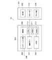
図1は第1の実施形態における情報処理システムの全体構成を示す図である。LAN(Local Area Network)105には、画像生成サーバ102、Webサーバ103およびMFP107が互いに通信可能に接続されている。また、MFP101および画像生成サーバ102は、ローカルネットワーク106を介して、互いに通信可能に接続されている。MFP101は画像生成サーバ102を介してLAN105に通信可能に接続される。なお、LAN105には、他の情報処理装置など(図示せず)が接続可能である。 FIG. 1 is a diagram illustrating an overall configuration of an information processing system according to the first embodiment. An
図2はMFP101の構成を示すブロック図である。MFP101はコントローラ部205および機能部201から構成される。 FIG. 2 is a block diagram illustrating a configuration of the
制御部208は、CPU210、ROM211およびRAM212を含み、MFP101の全体の動作を制御する。CPU210は、ROM211に記憶された制御プログラムを読み出して読取制御や送信制御などの各種制御処理を実行する。RAM212は、CPU210の主メモリ、ワークエリア等の一時記憶領域として用いられる。HDD209は、画像データや各種プログラムを記憶する。 A
また、制御部208は、機能部201と接続され、操作部202、スキャナ部203およびプリンタ部204の動作を制御する。操作部202には、タッチパネル機能を有する液晶表示部やキーボードなどが備えられている。さらに、操作部202には、後述するWebブラウザ機能が備えられている。MFP101のWebブラウザは、画像生成サーバ102から受信したHTMLファイルを解析し、受信したHTMLファイルの記述に基づく操作画面を操作部202に表示する。 The
プリンタ部204は、制御部208から入力された印刷すべき画像データを記録媒体(紙媒体)に印刷する。スキャナ部203は、原稿の画像を読み取って画像データを生成し、制御部208に入力する。インターフェイス部206は、制御部208をローカルネットワーク106に接続し、画像生成サーバ102から印刷用の画像データや情報を受信したり、操作部202で表示される画面データ(画面情報)を受信する。 The
なお、画像生成サーバ102から受信した印刷画像は、画像メモリ207に一時的に格納され、制御部208を介してプリンタ部204により印刷される。 Note that the print image received from the
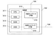
図3は画像生成サーバ102の構成を示すブロック図である。画像生成サーバ102内の制御部310は、CPU311、ROM312、RAM313、ハードディスクドライブ(HDD)314、外部ネットワークI/F部316および内部ネットワークI/F部315を有し、画像生成サーバ102全体の動作を制御する。 FIG. 3 is a block diagram showing a configuration of the
CPU311は、ROM312に記憶された制御プログラムを読み出して各種制御処理を実行する。RAM313は、CPU311の主メモリ、ワークエリア等の一時記憶領域として用いられる。HDD314は、画像データや各種プログラムを記憶する。また、内部ネットワークI/F部315は、制御部310をローカルネットワーク106に接続する。外部ネットワークI/F部316は、制御部310をLAN105に接続された他の情報処理装置に接続する。 The
図4はWebサーバ103の構成を示すブロック図である。Webサーバ103内の制御部410は、CPU411、ROM412、RAM413、ハードディスクドライブ(HDD)414およびネットワークI/F部415を有し、Webサーバ103の全体の動作を制御する。 FIG. 4 is a block diagram showing the configuration of the
CPU411は、ROM412に記憶された制御プログラムを読み出して各種制御処理を実行する。RAM413は、CPU411の主メモリ、ワークエリア等の一時記憶領域として用いられる。HDD414は、画像データや各種プログラムを記憶する。ネットワークI/F部415は、制御部410をLAN105に接続する。 The
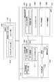
図5は情報処理システム全体のソフトウェア構成を説明するための図である。MFP101、画像生成サーバ102、Webサーバ103はそれぞれ図1に示した構成に対応する。なお、図5に示す各ソフトウェア機能は、図2のMFP101、図3の画像生成サーバ102、図4のWebサーバ103にそれぞれ備えられているCPUが制御プログラムを実行することにより実現される。 FIG. 5 is a diagram for explaining the software configuration of the entire information processing system. The
図5に示すように、MFP101は、Webブラウザ501、サービスプロバイダ504、プリンタ制御部505およびスキャナ制御部506を備える。 As illustrated in FIG. 5, the
Webブラウザ501は、リクエスト処理部502および画面表示部503を含む。リクエスト処理部502は、HTTPプロトコルに従って、画面表示部503に表示される画面情報をWebサーバ103のプレゼンテーション部516に要求する。 The
ここで、リクエスト処理部502がプレゼンテーション部516と行う通信は、プロキシ部507を中継することで実現される。より具体的に、リクエスト処理部502は、Webブラウザ501で表示されるMFPの操作画面情報をプロキシ部507に対して要求したり、画面表示部503に表示された操作画面を介して入力されたユーザからの指示をプロキシ部507に通知する。 Here, communication performed by the
また、リクエスト処理部502は、プロキシ部507から受信するHTMLファイルを解析する。このHTMLファイルには、Webブラウザ501に表示すべき操作画面の内容を示す記述が含まれている。画面表示部503は、リクエスト処理部502による解析の結果に基づき、MFP101の操作部202に操作画面を表示する。 In addition, the
サービスプロバイダ504は、MFP101内の機能をネットワーク上のWebサーバ103に公開する。公開される機能には、例えば、スキャナ制御部506で紙原稿をスキャンすることで電子データ化し、他の情報処理装置に送信する機能(Send機能)等が含まれる。 The
プリンタ制御部505は、プリンタ部204を制御し、画像生成サーバ102内のRIP部513(所定の機能部)で生成された印刷用のイメージデータを紙媒体に出力させる。 A
また、画像生成サーバ102は、プロキシ部507、RIP設定部512、サービスプロバイダ511、PDL受信部514およびRIP部513を備える。 The
プロキシ部507は、MFP101のWebブラウザ501やサービスプロバイダ504からの処理要求(リクエスト)を受ける。この処理要求は、メッセージ処理部508で解析される。そして、後述するように、プロキシ部507は、メッセージ内容に応じてデータ変換部509でリクエストを更新し、LAN105上のWebサーバ103にリクエストを発行する。また、プロキシ部507は、Webサーバ103へのリクエストに対するWebサーバ103からのレスポンスを、後述する方法を用いて編集した上で、MFP101のWebブラウザ501に送信する。 The
PDL受信部514は、ネットワーク(図示せず)上の印刷アプリケーションから印刷データであるPDL(Printer Description Language)を受信し、RIP部513に送信する。 The
RIP部513は、受信した印刷データをMFP101で出力可能なイメージデータに変換し、プリンタ制御部505に送信する。 The
RIP設定部512(機能設定部)は、RIP部513の動作を設定するWebアプリケーションである。RIP部513は、RIP設定部512で設定された設定内容に応じて動作する。本実施形態では、RIP設定部512はWebアプリケーションで構成されているので、ユーザは、Webブラウザ501を介してRIP設定部512にアクセスし、RIP部513の動作を設定することが可能である。 The RIP setting unit 512 (function setting unit) is a Web application that sets the operation of the
サービスプロバイダ511は、画像生成サーバ102内の機能を外部にAPIとして公開する。公開される機能として、例えば、電子データの送信先アドレス検索機能等がある。 The
また、Webサーバ103には、Webアプリケーション515が備わっている。さらに、Webアプリケーション515には、プレゼンテーション部516およびロジック部517が含まれる。 Further, the
プレゼンテーション部516は、プロキシ部507からの処理要求に応えてMFP101のWebブラウザ501で表示される操作画面情報を生成し、送信する。また、プレゼンテーション部516は、MFP101のWebブラウザ501に表示された操作画面を介して入力されたユーザからの指示をプロキシ部507から受け取る。 The
Webアプリケーション515は、ユーザからの指示を受け取ると、その指示の内容に従って各種処理を実行するとともに、MFP101のサービスプロバイダ504に対して処理の実行を依頼することも可能である。このとき、サービスプロバイダ504に対する処理の依頼は、プロキシ部507を経由して行われる。 When the
具体的に、MFP101のプリンタ制御部505による印刷処理の実行、スキャナ制御部506による紙原稿読取処理の実行、あるいはLAN105上のファイルサーバ(図示せず)への送信処理の実行を依頼すること等が可能である。 Specifically, execution of printing processing by the
このように、MFP101に対する処理の実行を依頼する場合、ロジック部517は、MFP101に備えられたサービスプロバイダ504に対し、処理の依頼を行う。 As described above, when requesting the
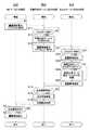
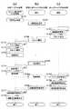
上記構成を有する情報処理システムの動作を示す。図6は情報処理システムにおける画面情報の表示手順を示すフローチャートである。同図(a)はMFP101の処理を示し、同図(b)は画像生成サーバ102の処理を示し、同図(c)はWebサーバ103の処理を示す。ここでは、Webブラウザ501がWebサーバ103に画像表示部503で表示すべき画面情報を要求する。Webサーバ103は、要求された画面情報であるHTMLファイルを生成する。画像生成サーバ102のプロキシ部507は、MFP101とWebサーバ103の通信を中継し、RIP設定部512にアクセスするためのURL情報をこのHTMLファイルに埋め込み、画像表示部503からの操作によってこのURLにアクセス可能にする。 The operation of the information processing system having the above configuration will be described. FIG. 6 is a flowchart showing a display procedure of screen information in the information processing system. 3A shows the processing of the
具体的に、MFP101の起動時、Webブラウザ501のリクエスト処理部502は、画像表示部503に表示すべき画面情報をプロキシ部507に要求する(ステップS1)。 Specifically, when the
プロキシ部507内のメッセージ処理部508は、この要求(HTTPリクエスト)を受け取ると(第1の要求受信手段)、この要求を解析する(ステップS11、要求解析手段)。データ変換部509は、このHTTPリクエストに画像生成サーバ102の識別情報を埋め込む(ステップS12、識別情報設定手段)。そして、メッセージ処理部508は、データ変換部509によって変更されたHTTPリクエストをWebサーバ103に送信する(ステップS13、要求送信手段)。 When the
ここで、ステップS12で示したHTTPリクエストへの識別情報の埋め込みでは、HTTPリクエストのヘッダ部分に識別子を埋め込むことや、URLに識別子を埋め込んで送信することが可能である。なお、本実施形態では、HTTPリクエストヘッダのUser−Agent属性に識別子を埋め込む例を説明する。 Here, in the embedding of the identification information in the HTTP request shown in step S12, it is possible to embed an identifier in the header part of the HTTP request or to embed the identifier in the URL for transmission. In this embodiment, an example will be described in which an identifier is embedded in the User-Agent attribute of the HTTP request header.
図7はHTTPリクエストのヘッダのUser−Agent属性に識別子を埋め込んだ例を示す図である。同図(a)はリクエスト処理部502から送信されたHTTPリクエストを示す。同図(b)はデータ変換部509で書き換えられたHTTPリクエストを示す。同図(a)のHTTPリクエストでは、符号1201に示すように、MFP101の識別子である“MFP”という識別情報が埋め込まれている。また、同図(b)のHTTPリクエストでは、符号1202に示すように、データ変換部509によって書き換えられた“RIPServer1”という識別子が埋め込まれている。 FIG. 7 is a diagram illustrating an example in which an identifier is embedded in the User-Agent attribute of the HTTP request header. FIG. 5A shows an HTTP request transmitted from the
Webサーバ103のプレゼンテーション部516は、ステップS13で生成されたHTTPリクエストを受け取ると(ステップS21、第2の要求受信手段)、画面表示部503で表示する表示情報(HTML)を生成する(ステップS22)。 Upon receiving the HTTP request generated in step S13 (step S21, second request receiving means), the
さらに、プレゼンテーション部516は、このHTTPリクエストが画像生成サーバ102によって生成されたものか否かを判定する(ステップS23、送信元特定手段)。この判定は、前述したように、HTTPリクエストヘッダのUser−Agent属性で行うことが可能である。 Further, the
ステップS23でHTTPリクエストが画像生成サーバ102からのリクエストであると判定された場合、プレゼンテーション部516は、画面生成サーバ設定用の設定コントロール情報を画面情報(HTML)に埋め込む(ステップS24、第2の情報変更手段)。 When it is determined in step S23 that the HTTP request is a request from the
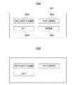
図8はHTMLファイルを示す図である。同図(a)はステップS24でプレゼンテーション部516によって作成されたHTMLファイルを例示する。符号1001に示すように、HTMLのDIVタグ及びCLASS属性を使って、この部分のユーザインターフェイスコントロールが追加されている。 FIG. 8 shows an HTML file. FIG. 5A illustrates an HTML file created by the
また、符号1002は、HTML書式のAタグを使ってこのボタンが押された場合に参照されるWebサーバの記載を行う領域である。なお、符号1002に示すように、ステップS24の段階では、Aタグの参照属性であるHREF属性には何も記載されていない。すなわち、このHTMLファイルは、画像生成サーバ102で変更可能な画面情報である。
プレゼンテーション部516は、ステップS24で生成されたHTMLファイルをメッセージ処理部508に送信する(ステップS25、第2の情報送信手段)。この後、Webサーバ103は本処理を終了する。 The
一方、ステップS23で画面情報要求のリクエストが画像生成サーバ102からではないと判定された場合、プレゼンテーション部516は、ステップS22で生成された画面情報をステップS25で送信する。この場合、画面情報は、図8において、符号1001のDIVタグ内部が存在しないHTMLファイルとなる。この後、Webサーバ103は本処理を終了する。 On the other hand, when it is determined in step S23 that the request for screen information is not from the
画像生成サーバ102では、プロキシ部507内のメッセージ処理部508がステップS25で発行された画面情報を受信する(ステップS14、第2の情報受信手段)。そして、プロキシ部507内のデータ変換部509は、HTMLファイルの編集を行う(ステップS15、情報変更手段)。 In the
図9はステップS15における画面情報編集手順を示すフローチャートである。データ変換部509は、ステップS24で生成されたHTMLファイルにおいて、符号1001で示されるDIVタグ内のクラス属性で識別されるタグを検索する(ステップS51)。そして、データ変換部509は、検索されたタグ内のA属性にRIP設定部512のURL情報を埋め込む(ステップS52)。この後、画像生成サーバ102は元の処理に復帰する。 FIG. 9 is a flowchart showing the screen information editing procedure in step S15. The
図8(b)はデータ変換部509によってステップS52で書き換えられたHTMLファイルの例を示す。図8(b)において、符号1003に示すように、タグ内のA属性に、RIP設定部512のURL情報である“http://RIPServer1.xxx.yyy.zzz”というURL情報が埋め込まれている。 FIG. 8B shows an example of an HTML file rewritten by the
メッセージ処理部508は、ステップS52で生成されたHTMLファイルをWebブラウザ501のリクエスト処理部502に送信する(ステップS16、第1の情報送信手段)。この後、画像生成サーバ102は本処理を終了する。 The
リクエスト処理部502は、このHTMLを受信すると(第1の情報受信手段)、このHTMLファイルを解析する(ステップS2)。そして、画像表示部503は、操作部202にこの画面情報を表示する(ステップS3)。この後、MFP101は本処理を終了する。 Upon receiving this HTML (first information receiving means), the
図10はステップS3で画像表示部503により操作部202に表示されるユーザインターフェイスの例を示す図である。この画面はMFP101の操作部202に表示されるものであり、ステップS52で生成されたHTMLファイルをリクエスト処理部502が解釈した画面である。 FIG. 10 is a diagram illustrating an example of a user interface displayed on the
同図(a)において、MFP101の操作部202には、画面801が表示される。また、画面801には、MFP101の機能別の処理を行うボタン802、803、804が配置されている。これら各ボタンを押下することで、操作部202は、機能を実現する第2階層のユーザインターフェイスを表示する。 In FIG. 9A, a
また、画面801には、本発明に係る“RIP設定”ボタン805が設けられている。このボタン805を押下することで、Webブラウザ501は、RIP設定部512にアクセスし、本Webブラウザを介してRIP部513の動作設定を行うことが可能となる。また、ボタン805は、HTMLでは図8(a)の符号1001で示したコントロールに対応している。このボタン805を押下したときに接続されるURLは、図8(b)の符号1003で示したURLとなる。 Further, the
また、図10(b)は、ステップS23で画像情報要求が画像生成サーバ102からのリクエストと判断されなかった場合に生成された画面を示す。この画面では、 “RIP設定”ボタン805は配置されない。つまり、Webブラウザ501から、プロキシ部507を経由せずに直接、Webサーバ103に画面情報要求を行った場合、図10(b)に示す画面が表示される。 FIG. 10B shows a screen generated when the image information request is not determined to be a request from the
図11はRIP設定ボタン805が押された場合の画面情報の表示手順を示すフローチャートである。同図(a)はMFP101の処理を示し、同図(b)は画像生成サーバ102の処理を示す。RIP設定ボタン805が押下されると、Webブラウザ501のリクエスト処理部502は、画面要求(リクエスト)を行う(ステップS71)。この画面要求の接続先のURLは、図8の符号1003で示されるHTMLに従い、RIP設定部512となる。 FIG. 11 is a flowchart showing a display procedure of screen information when the
画像生成サーバ102のRIP設定部512は、画面要求を受け取ると(ステップS81)、画面情報であるHTMLファイルを生成する(ステップS82)。RIP設定部512は、生成したHTMLファイルをリクエスト処理部502に送信する(ステップS83)。この後、画像生成サーバ102は本処理を終了する。 Upon receiving the screen request (step S81), the
一方、MFP101のリクエスト処理部502は、画面情報を受け取ると(ステップS72)、HTMLファイルを解釈し、この解釈結果を画面表示部503により操作部202に表示する(ステップS73)。この後、MFP101は本処理を終了する。 On the other hand, when receiving the screen information (step S72), the
図12はステップS73において画面表示部503により表示された画面を示す図である。この画面は、MFP101の操作部202に表示されるものであり、ステップS82でRIP設定部512により生成されたHTMLファイルをリクエスト処理部502が解釈した画面である。 FIG. 12 shows the screen displayed by the
コントロール901、902は、RIP部513の動作を設定する。本実施形態では、コントロール901、902は、PDL受信部514が受信した印刷データを用いて、RIP部513がどのような画像データを生成するかを設定可能であることを示す。つまり、コントロール901、902で示したRIP部513の2つの動作モードが選択可能となっている。具体的に、コントロール901は、「高速に画像を生成する」動作モードが設定可能である。一方、コントロール902は、「画質優先で画像を生成する」動作モードが設定可能である。
ボタン903は、コントロール901、902で選択された設定をRIP部513の動作に反映させるボタンである。このボタン903を押下することで、これ以後、RIP部513は、コントロール901、902で選択された設定に従い、動作することになる。キャンセルボタン904は、コントロール901、902で行った設定変更を、このボタン904を押下することで、キャンセルすることができる。 A
このように、第1の実施形態の情報処理システムによれば、Webブラウザ501は、Webサーバ103が生成した画面構成のHTMLファイルを解釈し、ユーザはWebブラウザ501を通してRIP部513の動作設定を行うことができる。 As described above, according to the information processing system of the first embodiment, the
また、画像生成サーバ102はWebサーバ103から送信される画面情報を受信し、MFP101に表示される画面情報を変更する。この際、Webサーバ103は、MFP101に表示される全体の画面情報を生成する。また、画像生成サーバ102は、画像生成サーバ102固有の画面情報に変更することができる。これにより、Webサーバ103の構築の汎用性を保ち、Webサーバ103の負荷を軽減することができる。また、Webサーバ103から送信された画面情報を変更することで、Webサーバ103から送信される画面情報に汎用性を持たせることができる。また、画像生成サーバ102の機能に合わせて、Webサーバ103で生成される画面情報を容易に変更することができる。また、Webサーバ103は、送信元である画像生成サーバ102の機能に適した画面情報を生成することができる。また、ユーザはMFP101の画面から画像生成サーバ102の機能を利用することができる。また、全ての画面操作をMFP101の操作部から行うことができ、操作性を高めることができる。また、MFP101および画像生成サーバ102間でデータを高速に転送することができる。 Further, the
(第2の実施形態)
図13は第2の実施形態における情報処理システムの全体構成を示す図である。前記第1の実施形態と同一の構成要素においては、同一の符号を付すことによりその説明を省略する。(Second Embodiment)
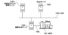
FIG. 13 is a diagram showing the overall configuration of the information processing system in the second embodiment. The same components as those in the first embodiment are denoted by the same reference numerals, and the description thereof is omitted.
第2の実施形態では、ネットワーク上に、MFP101から電子データを送信する宛先アドレスを決定するための検索サーバ1301が存在する。この検索サーバ1301は、MFP101、画像生成サーバ102およびWebサーバ103と連携する。 In the second embodiment, a
図14A、図14Bおよび図14Cは操作部202に表示される画面情報を示す図である。第2の実施形態におけるWebブラウザ501は、図10(a)及び図14Aの(a)〜図14Cの(f)に示す画面情報を表示する。 14A, 14B, and 14C are diagrams showing screen information displayed on the
図10(a)及び図14A〜図14Cを用いて、Webブラウザ501が表示する画面の流れを説明する。Webブラウザ501が表示する図10(a)の画面において、“スキャン&ファイル送信”ボタン802が押下されると、図14Aの(a)に示す画面を生成する画面情報が生成される。 A flow of a screen displayed by the
図14Aの(a)に示す画面には、“スキャンを実行する”ボタン1403が配置されている。このボタン1403を押下すると、スキャナ制御部506は、MFP101にセットされた紙原稿のスキャンを実行し、その電子データを、送信先メールアドレス1401に設定される送信先に送信する。 On the screen shown in FIG. 14A, an “Execute Scan”
ここで、送信先メールアドレス1401として、宛先検索サーバ1301または画像生成サーバ102のサービスプロバイダ511を用いて送信先を検索することが可能である。送信先メールアドレス1401は、“送信先を検索する”ボタン1402を押下することで表示される図14Aの(b)の画面を用いて設定可能となる。 Here, it is possible to search for a transmission destination using the
図14Aの(b)の画面において、検索サーバ格納領域1404は、利用可能な宛先検索サーバのリストを表示する領域である。この例では、2つの宛先検索サーバ1405、1406がリストされている。本実施形態では、宛先検索サーバ1405は画像生成サーバ102に相当し、宛先検索サーバ1406は送信先アドレス検索サーバ1301に相当する。 In the screen of FIG. 14A (b), the search
図14Aの(b)の画面において、MFP101の操作画面を操作する際、ユーザは検索キーワード格納領域1407に宛先アドレスの検索キーワードを入力する。検索キーワードの入力後、検索実行ボタン1408を押下すると、検索サーバ格納領域1404において選択された宛先検索サーバで送信先の検索が行われる。 When operating the operation screen of the
さらに、検索結果である、検索キーワード格納領域1407に記載されたキーワードに合致する宛先リストが、検索結果格納領域1409にリストされる。 Further, a destination list that matches the keyword described in the search
例として、図14Aの(b)の画面において検索サーバ格納領域1404に示すように、ユーザは、宛先検索サーバとして画像生成サーバ102である“RIPServer1.xxx.yyy.zzz”を選択する。さらに、ユーザは、図14Bの(c)の画面において検索キーワード格納領域1407に“abc”と検索キーワードを入力する。そして、ユーザが検索実行ボタン1408を押下すると、検索結果リスト1409には、図14Bの(d)の画面において検索キーワードに合致するリストとして、メールアドレス1412、1413が表示される。 As an example, as shown in the search
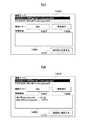
この図14Bの(d)の画面において、検索結果リスト1409から任意の宛先を選択し、“送信先に指定する”ボタン1410が押下されると、図14Cの(e)に示す画面に送信先メールアドレス1401が設定される。 When an arbitrary destination is selected from the
そして、図14Cの(e)の画面において“スキャンを実行する”ボタン1403が押下されると、紙原稿のスキャンが実行され、図14Cの(f)に示す結果画面が表示される。 When the “execute scan”
図15は図14Aの(a)の画面において、“送信先を検索する”ボタン1402が押下された場合の画面情報の表示手順を示すフローチャートである。同図(a)はMFP101の処理を示し、同図(b)は画像生成サーバ102の処理を示し、同図(c)はWebサーバ103の処理を示す。 FIG. 15 is a flowchart showing a display procedure of screen information when the “search for transmission destination”
MFP101では、“送信先を検索する”ボタン1402が押下されると、Webブラウザ501のリクエスト処理部502は、画面情報要求を行う(ステップS101)。 In the
画像生成サーバ102のメッセージ処理部508は、この画面情報要求を受けると、このリクエストをWebサーバ103に送信する(ステップS111)。 Upon receiving this screen information request, the
Webサーバ103のプレゼンテーション部516は、このリクエストを受けると、図14Aの(b)の画面情報に相当するHTMLファイルを生成し(ステップS121)、メッセージ処理部508に送信する(ステップS122)。なお、この時点ではHTMLファイル内にサービスプロバイダ511のアドレスは含まれておらず、後述するステップS114の処理を経て14Aの(b)の画面情報に相当するHTMLファイルが完成する。この後、Webサーバ103は本処理を終了する。 Upon receiving this request, the
画像生成サーバ102のメッセージ処理部508は、プレゼンテーション部516が生成したHTMLファイルを受信する(ステップS112)。そして、メッセージ処理部508は、このHTMLファイルから宛先検索サーバのリストを行っているユーザインターフェイスコントロール(リストコントロール)を検索する(ステップS113)。 The
さらに、データ変換部509は、サービスプロバイダ511のアドレスをリストコントロールに追加する(ステップS114)。ここで、サービスプロバイダ511は宛先検索サーバ1301と同様、宛先を検索する機能を有する。 Further, the
メッセージ処理部508は、データ変換部509によって変更されたHTMLファイルをWebブラウザ501のリクエスト処理部502に送信する(ステップS115)。この後、画像生成サーバ102は本処理を終了する。 The
リクエスト処理部502は、ステップS115で生成された画面情報であるHTMLファイルを受信すると(ステップS102)、このHTMLファイルを解釈し、画面表示部503に図14Aの(b)に示す画面を表示する(ステップS103)。この後、MFP101は本処理を終了する。 When the
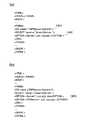
図16はステップS121でWebサーバ103によって生成されたHTMLファイル、およびステップS114で変更されたHTMLファイルの一部の例を示す図である。同図(a)はステップS121で生成されたHTMLファイルの例を示す。符号1601で示されるHTMLのDIVタグの内部は、宛先検索サーバ格納領域(リスト)1404にリストされるサーバを示す。また、符号1602に示すように、リスト要素を示すOPTIONタグには、宛先検索サーバ1301を示す“Server1.xxx.yyy.zzz”のみがリストされている。 FIG. 16 is a diagram showing an example of the HTML file generated by the
同図(b)はステップS114で生成されるHTMLファイルの例を示す。データ変換部509は、ステップS113で前述したDIVタグを検索し、ステップS114で宛先検索サーバのリストの要素を示すOPTIONタグに画像生成サーバ102のアドレスである“RIPServer1.xxx.yyy.zzz”を追加する。 FIG. 5B shows an example of the HTML file generated in step S114. In step S113, the
図17は図14Bの(c)の画面において、検索キーワード格納領域1407にキーワードとして“abc”を入力し、検索実行ボタン1408が押下された場合の画面情報の表示手順を示すフローチャートである。同図(a)はMFP101の処理を示し、同図(b)は画像生成サーバ102の処理を示し、同図(c)はWebサーバ103の処理を示す。 FIG. 17 is a flowchart showing a display procedure of screen information when “abc” is entered as a keyword in the search
検索実行ボタン1408が押下されると、Webブラウザ501のリクエスト処理部502は、画面設定情報の送信を行う(ステップS141)。この画面設定情報とは、図14Bの(c)の画面において、MFP101の画面操作により設定された設定値、つまり、検索キーワードである“abc”と検索サーバ名である。これらの画面設定情報は、以後の説明において、MFP101、画像生成サーバ102およびWebサーバ103間のあらゆる通信において伝達されているものとする。 When the
画像生成サーバ102のメッセージ処理部508は、画面設定情報を受けると、この画面設定情報をWebサーバ103に送信する(ステップS151)。 When receiving the screen setting information, the
Webサーバ103のロジック部517は、画面設定情報を受けると(ステップS161)、メッセージ処理部508に対して検索実行要求を行う(ステップS162)。 When the
メッセージ処理部508は、この検索実行要求を受けると、MFP101のサービスプロバイダ504に検索実行要求を行う(ステップS152)。 Upon receiving this search execution request, the
MFP101のサービスプロバイダ504は、検索実行要求を受け取ると(ステップS142)、この検索実行要求を解析し、宛先検索サーバを決定する(ステップS143)。ここで、宛先検索サーバとして、図14Aの(b)の宛先検索サーバ1405である画像生成サーバ102が選択されていた場合、リクエスト処理部502は、画像生成サーバ102のサービスプロバイダ511に宛先検索要求を送信する(ステップS144)。 Upon receiving the search execution request (step S142), the
サービスプロバイダ511は、宛先検索要求を受け付けると、検索要求を実行し(ステップS153)、この検索結果をサービスプロバイダ504に送信する(ステップS154)。なお、ステップS153で実行された検索結果は、図14Bの(d)の画面に示すメールアドレス1412、1413のリストである。 When receiving the destination search request, the
MFP101のサービスプロバイダ504は、検索結果を受信すると(ステップS145)、メッセージ処理部508に検索結果を送信する(ステップS146)。 Upon receiving the search result (step S145), the
メッセージ処理部508は、この検索結果を受信すると、受信した検索結果をロジック部517に送信する(ステップS155)。 When receiving the search result, the
ロジック部517がこの検索結果を受信すると(ステップS163)、プレゼンテーション部516は、この検索結果の画面情報を生成する(ステップS164)。ロジック部517は、この画面情報をメッセージ処理部508に送信する(ステップS165)。この後、Webサーバ103は本処理を終了する。 When the
さらに、メッセージ処理部508は、この画面情報をリクエスト処理部502に送信する(ステップS156)。この後、画像生成サーバ102は本処理を終了する。 Further, the
リクエスト処理部502は、この画面情報を受信すると(ステップS147)、この受信した画面情報を解釈し、画面表示部503によって表示する(ステップS148)。この後、MFP101は本処理を終了する。 Upon receiving this screen information (step S147), the
このステップS148で表示される画面は図14Bの(d)に示すようになる。図14Bの(d)の画面において、検索結果として、メールアドレス1412が選択され、送信先に指定するボタン1410が押下されると、図14Cの(e)に示す画面となる。 The screen displayed in step S148 is as shown in (d) of FIG. 14B. When the
図18は図14Cの(e)に示す画面において“スキャンを実行する”ボタン1403が押下された場合の画面情報の表示手順を示すフローチャートである。同図(a)はMFP101の処理を示し、同図(b)は画像生成サーバ102の処理を示し、同図(c)はWebサーバ103の処理を示す。 FIG. 18 is a flowchart showing a screen information display procedure when the “execute scan”
“スキャンを実行する”ボタン1403が押下されると、Webブラウザ501のリクエスト処理部502は、画面設定情報を送信する(ステップS171)。この画面設定情報は、図14Cの(e)の画面において、MFP101の画面操作により設定された設定値、つまり、送信先メールアドレス1401である。なお、これらの画面設定情報は、以後の説明において、MFP101、画像生成サーバ102およびWebサーバ103間のあらゆる通信において伝達されているものとする。 When the “execute scan”
画像生成サーバ102のメッセージ処理部508は、画面設定情報を受信すると、この画面設定情報(メッセージ)をWebサーバ103に送信する(ステップS181)。 When receiving the screen setting information, the
Webサーバ103のプレゼンテーション部516が画面設定情報を受信すると(ステップS191)、ロジック部517は“スキャンを実行する”ボタン1403の機能を実行するための実行命令を発行する(ステップS192)。 When the
メッセージ処理部508は、実行命令を受信すると、この実行命令をMFP101のサービスプロバイダ504に送信する(ステップS182)。 When the
サービスプロバイダ504がこの実行命令を受信すると(ステップS172)、スキャナ制御部506は、MFP101の紙原稿のスキャン処理を実行する(ステップS173)。 When the
サービスプロバイダ504は、宛先情報である送信先メールアドレス1401に示される宛先にスキャンされた電子データの送信処理を行う(ステップS174)。 The
画像生成サーバ102のメッセージ処理部508は、電子データの送信処理を受け付けると、送信先メールアドレス1401に示される宛先に電子データを送信する(ステップS183)。このように、電子データの送信処理は、ステップS183でメッセージ処理部508を経由して送信先メールアドレス1401で示されるメールサーバに転送することで行われる。さらに、ステップS183では、メッセージ処理部508は、送信先メールアドレス1401に示される宛先から電子データの送信結果を受けると、この送信結果をサービスプロバイダ504に送信する。 When receiving the electronic data transmission process, the
サービスプロバイダ504は、送信結果を受信すると(ステップS175)、この送信結果をメッセージ処理部508に送信する(ステップS176)。メッセージ処理部508は、送信結果を受信すると、この受信した送信結果をWebサーバ103に送信する(ステップS184)。このように、送信結果は、サービスプロバイダ504からメッセージ処理部508を経由し、Webサーバ103に送信される。 Upon receiving the transmission result (step S175), the
プレゼンテーション部516は、この送信結果を受信すると(ステップS193)、この送信結果の画面情報を生成し(ステップS194)、この画面情報をメッセージ処理部508に送信する(ステップS195)。この後、Webサーバ103は本処理を終了する。 Upon receiving this transmission result (step S193), the
メッセージ処理部508は、この画面情報をWebブラウザ501のリクエスト処理部502に送信する(ステップS185)。このように、この画面情報は、メッセージ処理部508を経由し、Webブラウザ501のリクエスト処理部502に送信される。 The
さらに、リクエスト処理部502は、画面情報を受信すると(ステップS177)、画面情報の解析結果を画面表示部503により表示する(ステップS178)。このとき、表示される画面情報は、例えば図14Cの(f)の画面に示すようになる。この画面では、送信結果が正常に行われたことが示されている。この後、MFP101は本処理を終了する。 Further, when receiving the screen information (Step S177), the
第2の実施形態の情報処理システムによれば、Webブラウザ501はWebサーバ103が生成した画面構成のHTMLファイルを解釈する。ユーザはWebブラウザ501を通して画像生成サーバ102のサービスプロバイダ511が提供する機能を利用することが可能となる。 According to the information processing system of the second embodiment, the
以上、実施の形態を詳述したが、上記実施の形態は特許請求の範囲に係る発明を限定するものでなく、また実施の形態で説明されている特徴の組み合わせの全てが発明の解決手段に必須のものとは限らない。 Although the embodiments have been described in detail above, the above embodiments do not limit the invention according to the claims, and all combinations of the features described in the embodiments are the means for solving the invention. It is not always essential.
本発明は、例えば、システム、装置、方法、プログラム若しくは記憶媒体(記録媒体)等としての実施態様をとることが可能である。具体的には、複数の機器から構成されるシステムに適用してもよいし、また、1つの機器からなる装置に適用してもよい。 The present invention can take the form of, for example, a system, apparatus, method, program, or storage medium (recording medium). Specifically, the present invention may be applied to a system composed of a plurality of devices, or may be applied to an apparatus composed of one device.
また、上記実施形態では、画像処理装置として、例えばMFPからなる印刷装置に適用された場合を示したが、本発明は、印刷装置に限らず、ファクシミリ装置、スキャナ装置、光学機器など種々の画像処理装置に適用可能である。 In the above-described embodiment, the case where the image processing apparatus is applied to a printing apparatus including, for example, an MFP has been described. It is applicable to a processing device.
また、本発明は、以下の処理を実行することによっても実現される。即ち、上述した実施形態の機能を実現するソフトウェア(プログラム)を、ネットワーク又は各種記憶媒体を介してシステム或いは装置に供給し、そのシステム或いは装置のコンピュータ(またはCPUやMPU等)がプログラムを読み出して実行する処理である。 The present invention can also be realized by executing the following processing. That is, software (program) that realizes the functions of the above-described embodiments is supplied to a system or apparatus via a network or various storage media, and a computer (or CPU, MPU, or the like) of the system or apparatus reads the program. It is a process to be executed.
101 MFP
102 画像生成サーバ
103 Webサーバ
105 LAN
501 Webブラウザ
504、511 サービスプロバイダ
507 プロキシ部
512 RIP設定部
1301 送信先検索サーバ101 MFP
102
501
Claims (11)
Translated fromJapanese前記画像処理装置は、
前記第1の要求を、前記情報処理装置に送信する第1の要求送信手段と、
前記第1の要求送信手段が送信した前記第1の要求に応じて、前記第2の機能の動作設定がユーザ選択可能であることを示す第2の画面情報と前記第2の機能の動作設定用画面の提供先を示すアドレスを、前記情報処理装置から受信する第1の情報受信手段と、
前記第1の情報受信手段により受信した前記第2の画面情報に基づき生成される選択画面を表示する表示手段と、
前記選択画面で前記第2の機能の動作設定がユーザ選択されたとき、前記アドレスにアクセスするアクセス手段とを有し、
前記情報処理装置は、
前記画像処理装置からの前記第1の要求を受信する第1の要求受信手段と、
前記第1の要求受信手段が受信した前記第1の要求に、当該要求が前記情報処理装置を介して送信された旨の識別情報を付加した、第2の要求を前記情報提供装置に送信する第2の要求送信手段と、
前記第2の要求送信手段が送信した前記第2の要求に応じて、前記第2の画面情報及び、前記アドレスを前記情報処理装置に検索させる検索命令を前記情報提供装置から受信する第2の情報受信手段と、
前記第2の情報受信手段が受信した前記検索命令に基づき、前記アドレスを検索する検索手段と、
前記検索手段が検索した前記アドレスと、前記第2の情報受信手段が受信した前記第2の画面情報を前記画像処理装置に送信する第1の情報送信手段とを有し、
前記情報提供装置は、
外部から受信した要求が前記識別情報を含む場合、当該要求が、前記情報処理装置から送信された前記第2の要求であると判別し、前記第2の画面情報及び前記検索命令を生成する生成手段と、
前記生成手段が生成した前記第2の画面情報及び前記検索命令を前記情報処理装置に送信する第2の情報送信手段とを有することを特徴とする情報処理システム。When the image processing apparatushaving the first function, the information processing apparatushavingthe second function provided tothe image processing apparatus,and the request received from theoutside is the first request transmitted from the image processing apparatus And an information providing systemthat returns first screen information for enabling the user to perform operation setting of the first function to the image processing apparatus ,
The image processing apparatus includes:
Afirst request transmission means fortransmittingthe firstrequest, tothe information processing apparatus,
Second screen informationindicating that the operation setting of the second function can be selected by the user in response to the first request transmitted by the first request transmission means and the operation setting ofthe second function First information receiving means for receivingfrom the information processing apparatusan address indicating a provision destination of the screen for use ;
Display means for displaying aselection screen generated based onthe second screen information received by the first information receiving means;
Access means for accessing the address when an operation setting of the second function is selected by the user on the selection screen ;
The information processing apparatus includes:
A first request receiving means for receiving thefirst request from the image processing apparatus,
Whereinthe first request receiving means andthe first that has received therequest, sendsthe request to which is appended the identification information indicating that the transmitted through the information processing apparatus, asecond request to the information providing deviceA second request transmission means;
In response to thesecond request transmission unit thesecond transmissionrequest, the second screen information and the second forreceiving search instruction for retrieving said address to said information processing apparatus from said information providing apparatus Information receiving means;
Search meansfor searching for the address based on the search command received by the second information receiving means;
Theaddresssearched by thesearch means,and the first information transmission means for transmittingthe second screen informationreceived by the second information reception means to the image processing apparatus,
The information providing apparatus includes:
If the request received from the outside including the identification information, generatingthe saidrequest, it saiddetermined to be transmitted the second request from the information processingapparatus, to generatethe second screen informationand the search command Means,
The information processing system; and a second information transmitting means for transmittingthe second screen informationand the search instruction which the generating means has generatedto the information processing apparatus.
前記画像処理装置からの前記第1の要求を受信する要求受信手段と、
前記要求受信手段が受信した前記第1の要求に、前記要求が前記情報処理装置を介して送信された旨の識別情報を付加した、第2の要求を前記情報提供装置に送信する要求送信手段と、
前記要求送信手段が送信した前記第2の要求に応じて、前記画像処理装置において前記第2の機能の動作設定がユーザ選択可能であることを示す第2の画面情報、及び前記第2の機能の動作設定用画面の提供先を示すアドレスを前記情報処理装置に検索させる検索命令を前記情報提供装置から受信する情報受信手段と、
前記情報受信手段により受信した前記検索命令に基づき、前記アドレスを検索する検索手段と、
前記検索手段が検索した前記アドレスと、前記情報受信手段が受信した前記第2の画面情報を前記画像処理装置に送信する情報送信手段とを有することを特徴とする情報処理装置。An image processing apparatushaving a first function and anoperation setting of the first function can be executed by a user when the request received from the outside is the first request transmitted from the image processing apparatus. is connectedto the first screen information tothe information providing apparatusto be returned to the image processing apparatus, an information processing apparatus for providinga second function to the image processing apparatus,
Request receiving means for receivingthe first request fromthe image processing apparatus;
Request transmitting means for transmitting asecond request to the information providing apparatus,in which identification information indicating that the request has been transmitted via the information processing apparatus is added tothe first request received by the request receiving means. When,
Second screen information indicating that an operation setting of the second function can be selected by the user in the image processing apparatus in response tothe second request transmitted by the request transmission unit, and the second function Information receiving means for receiving, from the information providing apparatus,a search command for causing the information processing apparatus to search for an address indicating a provision destination of the operation setting screen ;
Search meansfor searching for the address based on the search command received by the information receiving means;
An information processing apparatuscomprising: the address searched by the search means; and an information transmission means for transmittingthe second screen informationreceived by the information reception means to the image processing apparatus.
前記第1の要求を、前記情報処理装置に送信する要求送信手段と、
前記要求送信手段が送信した前記第1の要求に応じて、前記第2の機能の動作設定がユーザ選択可能であることを示す第2の画像情報、及び前記第2の機能の動作設定用画面の提供先を示すアドレスを前記情報処理装置から受信する情報受信手段と、
前記第2の画面情報に基づき生成される選択画面を表示する表示手段と、
前記選択画面で前記第2の機能の動作設定がユーザ選択されたとき、前記アドレスにアクセスするアクセス手段とを有することを特徴とする画像処理装置。An image processing apparatus having a first function, an information processing apparatushaving a second function provided to the image processing apparatus,and a request received from outside is a first request transmitted from the image processing apparatus.An image processing apparatusconnected toan information providing apparatusthat returns first screen information to the image processing apparatus for enabling operation setting of the first function by a user at a certain time ,
Request transmitting meansfor transmittingthe first requestto the information processing apparatus ;
Second image information indicating that the operation setting of the second function can be selected by the user in response tothe first requesttransmitted by therequest transmitting means, and an operation setting screen for the second function Information receiving means for receivingfrom the information processing apparatusan address indicating the provision destination of
Display means for displaying aselection screen generated based onthe second screen information;
An image processing apparatuscomprising: an access unit that accesses the address when an operation setting of the second function is selected by the user on the selection screen .
外部から受信した要求が前記情報処理装置を介して送信された旨の識別情報を含む場合、当該要求が前記情報処理装置から送信された第2の要求であると判別し、前記画像処理装置において前記第2の機能の動作設定がユーザ選択可能であることを示す第2の画面情報を生成すると共に、前記第2の機能の動作設定用画面の提供先を示すアドレスを前記情報処理装置に検索させる検索命令を生成する生成手段と、
前記生成手段によって生成された前記第2の画面情報及び前記検索命令を前記情報処理装置に送信する情報送信手段とを有することを特徴とする情報提供装置。The image processing apparatushaving a firstfunction,and is connected via a networkto an information processing apparatushaving asecond function to be providedto the image processingapparatus,the request received from the external is transmitted from the image processing apparatus An information providing device forreturning, to the image processing device, first screen information for enabling an operation setting of the first function to be executed by a user when the request is one request ;
When the request received from the outside includes identification information indicating that the request has been transmitted via the information processing apparatus, the request is determined to be a second request transmitted from the information processing apparatus, and the image processing apparatus Generates second screen information indicating that the operation setting of the second function can be selected by the user,and searches the information processing apparatusfor an address indicating a provision destination of the operation setting screen of the second function Generating means for generatingsearch instructions to be executed;
An information providing apparatuscomprising: information transmitting meansfor transmittingthe second screen information generated by the generating meansand the search command to theinformation processing apparatus.
前記画像処理装置において、
前記第1の要求を、前記情報提供装置に送信する第1の要求送信ステップと、
前記第1の要求送信ステップで送信した前記第1の要求に応じて、前記第2の機能の動作設定がユーザ選択可能であることを示す第2の画面情報と前記第2の機能の動作設定用画面の提供先を示すアドレスを、前記情報処理装置から受信する第1の情報受信ステップと、
前記第1の情報受信ステップで受信した前記第2の画面情報に基づき生成される選択画面を表示する表示ステップと、
前記選択画面で前記第2の機能の動作設定がユーザ選択されたとき、前記アドレスにアクセスするアクセスステップとを有し、
前記情報処理装置において、
前記画像処理装置からの前記第1の要求を受信する第1の要求受信ステップと、
前記第1の要求受信ステップで受信した前記第1の要求に、当該要求が前記情報処理装置を介して送信された旨の識別情報を付加した、第2の要求を前記情報提供装置に送信する第2の要求送信ステップと、
前記第2の要求送信ステップで送信した前記第2の要求に応じて、前記第2の画面情報及び、前記アドレスを前記情報処理装置に検索させる検索命令を前記情報提供装置から受信する第2の情報受信ステップと、
前記第2の情報受信ステップで受信した前記検索命令に基づき、前記アドレスを検索する検索ステップと、
前記検索ステップで検索された前記アドレスと、前記第2の情報受信ステップで受信した前記第2の画面情報を前記画像処理装置に送信する第1の情報送信ステップとを有し、
前記情報提供装置において、
外部から受信した要求が前記識別情報を含む場合、当該要求が、前記情報処理装置から送信された前記第2の要求であると判別し、前記第2の画面情報及び前記検索命令を生成する生成ステップと、
前記生成ステップで生成された前記第2の画面情報及び前記検索命令を前記情報処理装置に送信する第2の情報送信ステップとを有することを特徴とする情報処理システムの制御方法。When the image processing apparatushaving the first function, the information processing apparatushavingthe second function provided tothe image processing apparatus,and the request received from theoutside is the first request transmitted from the image processing apparatus And a control method for an information processing system includingan information providing apparatusthat returns first screen information to the image processing apparatus for enabling operation setting of the first function by a user ,
In the image processing apparatus,
Afirst request transmission step oftransmittingthe first requestto said information providing apparatus,
Second screen informationindicating that the operation setting of the second function can be selected by the user in response to the first request transmitted in the first request transmission step and the operation setting ofthe second function A first information receiving step of receivingfrom the information processing apparatusan address indicating a destination for providing the screen for use ;
A display step for displaying aselection screen generated based onthe second screen information received in the first information receiving step;
An access step for accessing the address when an operation setting of the second function is selected by the user on the selection screen ;
In the information processing apparatus,
A first request receiving step of receiving thefirst request from the image processing apparatus,
Whereinthefirst request received by the first request receivingstep, and transmitsthe request to which is appended the identification information indicating that the transmitted through the information processing apparatus, asecond request to the information providing deviceA second request sending step;
Depending on the transmittedsecond request in thesecond request transmissionstep, the second screen information and the second forreceiving search instruction for retrieving said address to said information processing apparatus from said information providing apparatus An information receiving step;
A search stepof searching for the address based on the search command received in the second information receiving step;
A first information transmission step of transmitting theaddresssearched in thesearch step andthe second screen informationreceived in the second information reception step to the image processing device;
In the information providing apparatus,
If the request received from the outside including the identification information, generatingthe saidrequest, it saiddetermined to be transmitted the second request from the information processingapparatus, to generatethe second screen informationand the search command Steps,
Control method for an information processing system; and a second information transmitting step of transmittingthe second screen informationand the retrieval instruction generated in the generation stepto the information processing apparatus.
前記制御方法は、
前記画像処理装置において、
前記第1の要求を、前記情報提供装置に送信する第1の要求送信ステップと、
前記第1の要求送信ステップで送信した前記第1の要求に応じて、前記第2の機能の動作設定がユーザ選択可能であることを示す第2の画面情報と前記第2の機能の動作設定用画面の提供先を示すアドレスを、前記情報処理装置から受信する第1の情報受信ステップと、
前記第1の情報受信ステップで受信した前記第2の画面情報に基づき生成される選択画面を表示する表示ステップと、
前記選択画面で前記第2の機能の動作設定がユーザ選択されたとき、前記アドレスにアクセスするアクセスステップとを有し、
前記情報処理装置において、
前記画像処理装置からの前記第1の要求を受信する第1の要求受信ステップと、
前記第1の要求受信ステップで受信した前記第1の要求に、当該要求が前記情報処理装置を介して送信された旨の識別情報を付加した、第2の要求を前記情報提供装置に送信する第2の要求送信ステップと、
前記第2の要求送信ステップで送信した前記第2の要求に応じて、前記第2の画面情報及び、前記アドレスを前記情報処理装置に検索させる検索命令を前記情報提供装置から受信する第2の情報受信ステップと、
前記第2の情報受信ステップで受信した前記検索命令に基づき、前記アドレスを検索する検索ステップと、
前記検索ステップで検索された前記アドレスと、前記第2の情報受信ステップで受信した前記第2の画面情報を前記画像処理装置に送信する第1の情報送信ステップとを有し、
前記情報提供装置において、
外部から受信した要求が前記識別情報を含む場合、当該要求が、前記情報処理装置から送信された前記第2の要求であると判別し、前記第2の画面情報及び前記検索命令を生成する生成ステップと、
前記生成ステップで生成された前記第2の画面情報及び前記検索命令を前記情報処理装置に送信する第2の情報送信ステップとを有することを特徴とするプログラム。
When the image processing apparatushaving the first function, the information processing apparatushavingthe second function provided tothe image processing apparatus,and the request received from theoutside is the first request transmitted from the image processing apparatus Further, a program for causing a computer to execute a control method of an information processing system includingan information providing apparatusthat returns first screen information for enabling the user to perform operation setting of the first function to the image processing apparatus Because
The control method is:
In the image processing apparatus,
Afirst request transmission step oftransmittingthe first requestto said information providing apparatus,
Second screen informationindicating that the operation setting of the second function can be selected by the user in response to the first request transmitted in the first request transmission step and the operation setting ofthe second function A first information receiving step of receivingfrom the information processing apparatusan address indicating a destination for providing the screen for use ;
A display step for displaying aselection screen generated based onthe second screen information received in the first information receiving step;
An access step for accessing the address when an operation setting of the second function is selected by the user on the selection screen ;
In the information processing apparatus,
A first request receiving step of receiving thefirst request from the image processing apparatus,
Whereinthefirst request received by the first request receivingstep, and transmitsthe request to which is appended the identification information indicating that the transmitted through the information processing apparatus, asecond request to the information providing deviceA second request sending step;
Depending on the transmittedsecond request in thesecond request transmissionstep, the second screen information and the second forreceiving search instruction for retrieving said address to said information processing apparatus from said information providing apparatus An information receiving step;
A search stepof searching for the address based on the search command received in the second information receiving step;
A first information transmission step of transmitting theaddresssearched in thesearch step andthe second screen informationreceived in the second information reception step to the image processing device;
In the information providing apparatus,
If the request received from the outside including the identification information, generatingthe saidrequest, it saiddetermined to be transmitted the second request from the information processingapparatus, to generatethe second screen informationand the search command Steps,
Program; and a second information transmitting step of transmittingthe second screen informationand the retrieval instruction generated in the generation stepto the information processing apparatus.
Priority Applications (3)
| Application Number | Priority Date | Filing Date | Title |
|---|---|---|---|
| JP2009292789AJP5595032B2 (en) | 2009-12-24 | 2009-12-24 | Information processing system, control method therefor, information processing device, information providing device, image processing device, and program |
| US12/963,046US9160873B2 (en) | 2009-12-24 | 2010-12-08 | Information processing system controlling image processing apparatus to display screen information, control method therefor, external control apparatus, information provision apparatus, image processing apparatus, and storage medium storing program |
| CN201010608524.0ACN102123218B (en) | 2009-12-24 | 2010-12-21 | Information processing system, control method therefor, external control apparatus, information provision apparatus and image processing apparatus |
Applications Claiming Priority (1)
| Application Number | Priority Date | Filing Date | Title |
|---|---|---|---|
| JP2009292789AJP5595032B2 (en) | 2009-12-24 | 2009-12-24 | Information processing system, control method therefor, information processing device, information providing device, image processing device, and program |
Publications (2)
| Publication Number | Publication Date |
|---|---|
| JP2011135314A JP2011135314A (en) | 2011-07-07 |
| JP5595032B2true JP5595032B2 (en) | 2014-09-24 |
Family
ID=44188997
Family Applications (1)
| Application Number | Title | Priority Date | Filing Date |
|---|---|---|---|
| JP2009292789AExpired - Fee RelatedJP5595032B2 (en) | 2009-12-24 | 2009-12-24 | Information processing system, control method therefor, information processing device, information providing device, image processing device, and program |
Country Status (3)
| Country | Link |
|---|---|
| US (1) | US9160873B2 (en) |
| JP (1) | JP5595032B2 (en) |
| CN (1) | CN102123218B (en) |
Families Citing this family (11)
| Publication number | Priority date | Publication date | Assignee | Title |
|---|---|---|---|---|
| JP5673453B2 (en)* | 2011-09-07 | 2015-02-18 | ブラザー工業株式会社 | Communications system |
| KR101820721B1 (en)* | 2011-11-29 | 2018-01-23 | 에스프린팅솔루션 주식회사 | Image forming device for serving a web service and method thereof |
| JP5995460B2 (en)* | 2012-02-24 | 2016-09-21 | キヤノン株式会社 | Information processing apparatus, program, and control method |
| JP6492711B2 (en)* | 2015-02-04 | 2019-04-03 | 富士ゼロックス株式会社 | Relay device, operation screen providing device, and program |
| JP6455195B2 (en)* | 2015-02-04 | 2019-01-23 | 富士ゼロックス株式会社 | Operation screen providing system, relay device, and program |
| JP6733479B2 (en)* | 2016-03-17 | 2020-07-29 | 株式会社リコー | Information processing system, information processing apparatus, image forming apparatus, information processing method, and program |
| US10033898B2 (en) | 2016-03-17 | 2018-07-24 | Ricoh Company, Ltd. | Information processing system, image forming apparatus, and method of processing information |
| JP6776835B2 (en)* | 2016-11-16 | 2020-10-28 | コニカミノルタ株式会社 | Complex device, display switching method and display switching program |
| US10416940B2 (en)* | 2017-03-17 | 2019-09-17 | Ricoh Company, Ltd. | Image processing apparatus, image processing system, and image processing method for interpreting content obtained from a web browser and displaying a screen based on the interpreted content |
| US10592388B1 (en)* | 2018-09-26 | 2020-03-17 | Jpmorgan Chase Bank, N.A. | Methods for facilitating more efficient network message exchange and analysis and devices thereof |
| JP2024007023A (en)* | 2022-07-05 | 2024-01-18 | キヤノン株式会社 | Image processing system, relay server, and program |
Family Cites Families (20)
| Publication number | Priority date | Publication date | Assignee | Title |
|---|---|---|---|---|
| JPH10161947A (en)* | 1996-12-02 | 1998-06-19 | Sony Corp | Information processor |
| JP3922482B2 (en)* | 1997-10-14 | 2007-05-30 | ソニー株式会社 | Information processing apparatus and method |
| US6247048B1 (en)* | 1998-04-30 | 2001-06-12 | Openwave Systems Inc | Method and apparatus for transcoding character sets between internet hosts and thin client devices over data networks |
| US7168086B1 (en)* | 1998-11-30 | 2007-01-23 | Microsoft Corporation | Proxy for video on demand server control |
| US7210100B2 (en)* | 2000-09-27 | 2007-04-24 | Eizel Technologies, Inc. | Configurable transformation of electronic documents |
| US20040015484A1 (en)* | 2002-07-18 | 2004-01-22 | Philippe Debaty | Client context-aware proxy server system |
| JP2004185464A (en)* | 2002-12-05 | 2004-07-02 | Ricoh Co Ltd | Information processing apparatus, program, and recording medium |
| JP2004288040A (en)* | 2003-03-24 | 2004-10-14 | Fuji Xerox Co Ltd | Image processing apparatus, image processing method and image processing program |
| JP4340566B2 (en)* | 2003-04-01 | 2009-10-07 | 株式会社リコー | Web page generation apparatus, embedded apparatus, Web page generation control method, Web page generation program, and recording medium |
| JP4154316B2 (en)* | 2003-11-21 | 2008-09-24 | キヤノン株式会社 | Image processing system, control method, image processing apparatus, program, and storage medium |
| US6968150B2 (en)* | 2003-12-23 | 2005-11-22 | Sharp Laboratories Of America, Inc. | Systems and methods for adding post-collation operations and interleaved imaging jobs to an imaging job |
| KR100664320B1 (en)* | 2004-09-10 | 2007-01-04 | 삼성전자주식회사 | Image forming apparatus and control method thereof |
| JP2006121614A (en)* | 2004-10-25 | 2006-05-11 | Nec Commun Syst Ltd | Video distribution mediation system, video distribution mediation apparatus, video distribution mediation method, and video distribution mediation program |
| JP4539293B2 (en) | 2004-11-01 | 2010-09-08 | 富士ゼロックス株式会社 | Document processing system, document processing apparatus, device, UI display processing method and display processing program for document processing system |
| JP2006203808A (en)* | 2005-01-24 | 2006-08-03 | Canon Inc | Image processing apparatus, information processing apparatus, information processing system, information processing method, program, and storage medium |
| US20060290948A1 (en)* | 2005-06-27 | 2006-12-28 | Sharp Laboratories Of America, Inc. | Undesirable output detection in imaging device |
| JP2008139981A (en)* | 2006-11-30 | 2008-06-19 | Sharp Corp | Control device, terminal device, display system, display method, program, and recording medium thereof |
| JP4981461B2 (en)* | 2007-01-18 | 2012-07-18 | 株式会社日立製作所 | Information concealment method and information concealment device |
| US20080270911A1 (en)* | 2007-04-24 | 2008-10-30 | Nehal Dantwala | System and method to develop a custom application for a multi-function peripheral (mfp) |
| EP2015183B1 (en)* | 2007-06-08 | 2018-05-30 | Canon Kabushiki Kaisha | Image-forming apparatus and information-processing method |
- 2009
- 2009-12-24JPJP2009292789Apatent/JP5595032B2/ennot_activeExpired - Fee Related
- 2010
- 2010-12-08USUS12/963,046patent/US9160873B2/ennot_activeExpired - Fee Related
- 2010-12-21CNCN201010608524.0Apatent/CN102123218B/ennot_activeExpired - Fee Related
Also Published As
| Publication number | Publication date |
|---|---|
| CN102123218B (en) | 2014-05-28 |
| US20110161823A1 (en) | 2011-06-30 |
| JP2011135314A (en) | 2011-07-07 |
| CN102123218A (en) | 2011-07-13 |
| US9160873B2 (en) | 2015-10-13 |
Similar Documents
| Publication | Publication Date | Title |
|---|---|---|
| JP5595032B2 (en) | Information processing system, control method therefor, information processing device, information providing device, image processing device, and program | |
| KR101455405B1 (en) | Strategies for sending content to a target device | |
| JP4338905B2 (en) | Print instruction program and print instruction method for printer with PDF direct printing function | |
| JP2004318842A (en) | Web page generation device, embedded device, Web page generation control method, Web page generation program, and recording medium | |
| JP5462610B2 (en) | Information processing system, information processing apparatus, control method therefor, and program | |
| JP2004185464A (en) | Information processing apparatus, program, and recording medium | |
| JP2005269250A (en) | Data transmission apparatus | |
| JP2010118054A (en) | Thumbnail generation method and image forming apparatus | |
| KR20080056300A (en) | Cascading Job Flow Creation Device, Cascading Job Flow Creation Method, Service Processing Unit, Service Processing Method, Management Server, Flow Conversion Method, Job Flow Execution Method, and Storage Media | |
| JP4940982B2 (en) | Image forming apparatus and Web page printing control method | |
| JP6714839B2 (en) | Printing system, print management server, communication relay device, and program | |
| JP2012085176A (en) | Image forming apparatus, information apparatus and computer program | |
| JP2012257281A (en) | Service processing system | |
| JP2013232984A (en) | Service processing system | |
| JP2012216147A (en) | Data processing apparatus, data processing method, and program | |
| JP5516814B2 (en) | Service processing system | |
| JP2014041634A (en) | Service processing system | |
| JP2004303218A (en) | Information providing device and information display device | |
| JP5838795B2 (en) | Print data generation program, terminal device, and control method of terminal device | |
| JP4645833B2 (en) | Image forming apparatus, image forming program, and image forming system | |
| JP4154316B2 (en) | Image processing system, control method, image processing apparatus, program, and storage medium | |
| JP2014032685A (en) | Service processing system | |
| JP2014038639A (en) | Service processing system | |
| JP6115299B2 (en) | Relay device, image processing device, communication system, and relay device program | |
| JP2009130493A (en) | Network compatible image processing device |
Legal Events
| Date | Code | Title | Description |
|---|---|---|---|
| A621 | Written request for application examination | Free format text:JAPANESE INTERMEDIATE CODE: A621 Effective date:20121221 | |
| A977 | Report on retrieval | Free format text:JAPANESE INTERMEDIATE CODE: A971007 Effective date:20131210 | |
| A131 | Notification of reasons for refusal | Free format text:JAPANESE INTERMEDIATE CODE: A131 Effective date:20140107 | |
| A521 | Request for written amendment filed | Free format text:JAPANESE INTERMEDIATE CODE: A523 Effective date:20140307 | |
| TRDD | Decision of grant or rejection written | ||
| A01 | Written decision to grant a patent or to grant a registration (utility model) | Free format text:JAPANESE INTERMEDIATE CODE: A01 Effective date:20140708 | |
| A61 | First payment of annual fees (during grant procedure) | Free format text:JAPANESE INTERMEDIATE CODE: A61 Effective date:20140805 | |
| R151 | Written notification of patent or utility model registration | Ref document number:5595032 Country of ref document:JP Free format text:JAPANESE INTERMEDIATE CODE: R151 | |
| LAPS | Cancellation because of no payment of annual fees |