JP5591833B2 - System and method for providing a flow control valve for a medical device - Google Patents
System and method for providing a flow control valve for a medical deviceDownload PDFInfo
- Publication number
- JP5591833B2 JP5591833B2JP2011550230AJP2011550230AJP5591833B2JP 5591833 B2JP5591833 B2JP 5591833B2JP 2011550230 AJP2011550230 AJP 2011550230AJP 2011550230 AJP2011550230 AJP 2011550230AJP 5591833 B2JP5591833 B2JP 5591833B2
- Authority
- JP
- Japan
- Prior art keywords
- lumen
- pusher
- septum
- distal
- proximal
- Prior art date
- Legal status (The legal status is an assumption and is not a legal conclusion. Google has not performed a legal analysis and makes no representation as to the accuracy of the status listed.)
- Active
Links
Images


Classifications
- A—HUMAN NECESSITIES
- A61—MEDICAL OR VETERINARY SCIENCE; HYGIENE
- A61M—DEVICES FOR INTRODUCING MEDIA INTO, OR ONTO, THE BODY; DEVICES FOR TRANSDUCING BODY MEDIA OR FOR TAKING MEDIA FROM THE BODY; DEVICES FOR PRODUCING OR ENDING SLEEP OR STUPOR
- A61M25/00—Catheters; Hollow probes
- A61M25/0043—Catheters; Hollow probes characterised by structural features
- A—HUMAN NECESSITIES
- A61—MEDICAL OR VETERINARY SCIENCE; HYGIENE
- A61M—DEVICES FOR INTRODUCING MEDIA INTO, OR ONTO, THE BODY; DEVICES FOR TRANSDUCING BODY MEDIA OR FOR TAKING MEDIA FROM THE BODY; DEVICES FOR PRODUCING OR ENDING SLEEP OR STUPOR
- A61M25/00—Catheters; Hollow probes
- A61M25/01—Introducing, guiding, advancing, emplacing or holding catheters
- A61M25/06—Body-piercing guide needles or the like
- A61M25/0606—"Over-the-needle" catheter assemblies, e.g. I.V. catheters
- A—HUMAN NECESSITIES
- A61—MEDICAL OR VETERINARY SCIENCE; HYGIENE
- A61M—DEVICES FOR INTRODUCING MEDIA INTO, OR ONTO, THE BODY; DEVICES FOR TRANSDUCING BODY MEDIA OR FOR TAKING MEDIA FROM THE BODY; DEVICES FOR PRODUCING OR ENDING SLEEP OR STUPOR
- A61M39/00—Tubes, tube connectors, tube couplings, valves, access sites or the like, specially adapted for medical use
- A61M39/02—Access sites
- A61M39/06—Haemostasis valves, i.e. gaskets sealing around a needle, catheter or the like, closing on removal thereof
- A61M39/0606—Haemostasis valves, i.e. gaskets sealing around a needle, catheter or the like, closing on removal thereof without means for adjusting the seal opening or pressure
- A—HUMAN NECESSITIES
- A61—MEDICAL OR VETERINARY SCIENCE; HYGIENE
- A61M—DEVICES FOR INTRODUCING MEDIA INTO, OR ONTO, THE BODY; DEVICES FOR TRANSDUCING BODY MEDIA OR FOR TAKING MEDIA FROM THE BODY; DEVICES FOR PRODUCING OR ENDING SLEEP OR STUPOR
- A61M39/00—Tubes, tube connectors, tube couplings, valves, access sites or the like, specially adapted for medical use
- A61M39/02—Access sites
- A61M39/06—Haemostasis valves, i.e. gaskets sealing around a needle, catheter or the like, closing on removal thereof
- A61M2039/0633—Haemostasis valves, i.e. gaskets sealing around a needle, catheter or the like, closing on removal thereof the seal being a passive seal made of a resilient material with or without an opening
- A61M2039/064—Slit-valve
- A—HUMAN NECESSITIES
- A61—MEDICAL OR VETERINARY SCIENCE; HYGIENE
- A61M—DEVICES FOR INTRODUCING MEDIA INTO, OR ONTO, THE BODY; DEVICES FOR TRANSDUCING BODY MEDIA OR FOR TAKING MEDIA FROM THE BODY; DEVICES FOR PRODUCING OR ENDING SLEEP OR STUPOR
- A61M39/00—Tubes, tube connectors, tube couplings, valves, access sites or the like, specially adapted for medical use
- A61M39/02—Access sites
- A61M39/06—Haemostasis valves, i.e. gaskets sealing around a needle, catheter or the like, closing on removal thereof
- A61M2039/0633—Haemostasis valves, i.e. gaskets sealing around a needle, catheter or the like, closing on removal thereof the seal being a passive seal made of a resilient material with or without an opening
- A61M2039/066—Septum-like element
- A—HUMAN NECESSITIES
- A61—MEDICAL OR VETERINARY SCIENCE; HYGIENE
- A61M—DEVICES FOR INTRODUCING MEDIA INTO, OR ONTO, THE BODY; DEVICES FOR TRANSDUCING BODY MEDIA OR FOR TAKING MEDIA FROM THE BODY; DEVICES FOR PRODUCING OR ENDING SLEEP OR STUPOR
- A61M39/00—Tubes, tube connectors, tube couplings, valves, access sites or the like, specially adapted for medical use
- A61M39/02—Access sites
- A61M39/06—Haemostasis valves, i.e. gaskets sealing around a needle, catheter or the like, closing on removal thereof
- A—HUMAN NECESSITIES
- A61—MEDICAL OR VETERINARY SCIENCE; HYGIENE
- A61M—DEVICES FOR INTRODUCING MEDIA INTO, OR ONTO, THE BODY; DEVICES FOR TRANSDUCING BODY MEDIA OR FOR TAKING MEDIA FROM THE BODY; DEVICES FOR PRODUCING OR ENDING SLEEP OR STUPOR
- A61M39/00—Tubes, tube connectors, tube couplings, valves, access sites or the like, specially adapted for medical use
- A61M39/22—Valves or arrangement of valves
- A61M39/26—Valves closing automatically on disconnecting the line and opening on reconnection thereof
Landscapes
- Health & Medical Sciences (AREA)
- Life Sciences & Earth Sciences (AREA)
- Heart & Thoracic Surgery (AREA)
- Biomedical Technology (AREA)
- Engineering & Computer Science (AREA)
- Anesthesiology (AREA)
- Pulmonology (AREA)
- Hematology (AREA)
- Animal Behavior & Ethology (AREA)
- General Health & Medical Sciences (AREA)
- Public Health (AREA)
- Veterinary Medicine (AREA)
- Biophysics (AREA)
- Infusion, Injection, And Reservoir Apparatuses (AREA)
Description
Translated fromJapanese本開示は、患者へ注入または他の治療を提供するために使用される血管外システムにおける流体流れに関する。注入治療は最も一般的な医療行為のうちの1つである。入院および家庭で治療する患者は、血管系に挿入された血管アクセス機器を経た流体、調剤、および血液製剤を受け入れる。注入治療は、感染を治療し、麻酔または鎮痛を提供すること、栄養補給を提供すること、癌の成長を治療すること、血圧と心臓リズムを維持すること、あるいは、多くの他の医療上の重要な用途に使用される。 The present disclosure relates to fluid flow in an extravascular system used to provide infusion or other therapy to a patient. Infusion therapy is one of the most common medical practices. Patients who are hospitalized and treated at home accept fluids, preparations, and blood products via vascular access devices inserted into the vasculature. Infusion therapy treats infection, provides anesthesia or analgesia, provides nutrition, treats cancer growth, maintains blood pressure and heart rhythm, or many other medical treatments Used for important applications.
注入治療は、患者の血管系の外に配置された血管アクセス機器により促される。血管外システムは、少なくとも一の血管アクセス機器および/または患者の周辺のまたは中心的な血管系に直接、または、間接的にアクセスできる他の医療機器を含む。血管アクセス機器は、たとえば、ベクトン・ディキンソン社のBD Q−SYTETM密閉ルアーアクセス機器などの、密閉アクセス機器を含む。これは、 シリンジ、 分割されたアクセス機器、カテーテル、および、静脈内輸液用(IV)流体チャンバを含む。血管外システムは、短期(日)、適切な期間(週)または長期(数月から数年)の間、患者の血管系にアクセスし、および、継続的な注入治療または間欠的な治療のために使われる。 Infusion therapy is facilitated by a vascular access device located outside the patient's vasculature. Extravascular systems include at least one vascular access device and / or other medical devices that can directly or indirectly access a patient's peripheral or central vasculature. Vascular access devices include, for example, sealed access devices such as Becton Dickinson's BD Q-SYTE ™ closed luer access device. This includes syringes, segmented access devices, catheters, and intravenous fluid (IV) fluid chambers. The extravascular system accesses the patient's vasculature for short periods (days), appropriate periods (weeks), or long periods (months to years) and for continuous infusion or intermittent treatment Used for.
一般的な血管アクセス機器は、患者の静脈に挿入されるプラスチックのカテーテルである。カテーテルの長さは、周辺へのアクセスには数センチメートル、中心へのアクセスには数十センチメートルと、様々である。カテーテルは経皮的に挿入、または、患者の皮膚下に外科的に移植できる。カテーテル、または、これに取り付けられた他のいずれの血管アクセス機器は、単一のルーメン、または、多数の流体の同時注入のための複数のルーメンを持つことができる。 A common vascular access device is a plastic catheter that is inserted into a patient's vein. The length of the catheter varies from several centimeters for access to the periphery to tens of centimeters for access to the center. The catheter can be inserted percutaneously or surgically implanted under the patient's skin. The catheter, or any other vascular access device attached to it, can have a single lumen or multiple lumens for simultaneous infusion of multiple fluids.
カテーテルを配置するためのいくつかのテクニックが上記技術において実施されているけれども、多くの場合は、概ね、針の少なくとも一部分を目標の血管に挿入し、それから、カテーテルを針上の適所にスライドさせるステップを含む。医療従事者は、血管内のカテーテルの適切な配置を確認することを試みる。カテーテルハブ内のフラッシュバックチャンバや導入針のノッチなどの、血管のカテーテルの適切な配置を確認するための手段を含むカテーテルおよび導入針アセンブリが提供されている。 Although several techniques for placing a catheter have been implemented in the above techniques, in many cases, generally at least a portion of the needle is inserted into the target vessel and then the catheter is slid into place over the needle. Includes steps. The healthcare professional will attempt to verify proper placement of the catheter within the vessel. A catheter and introducer needle assembly is provided that includes means for confirming proper placement of the vascular catheter, such as a flashback chamber within the catheter hub and an introducer needle notch.
いったん針の配置がフラッシュの観察によって確認されると、ユーザーは一時的に、カテーテル先端で血管内の流れを閉ざし、針を取り除いてカテーテルを適所に残し、流体除去、入力あるいはカテーテルをシールするための機器をカテーテルに取り付ける。多くの配置場所は目標の血管の閉塞を容易には許容しないので、このプロセスは、実際には、多少困難である。さらに、そのような閉塞が達成される時にさえ、不完全であるかもしれず、したがって、血液のカテーテルからの漏れをもたらし、それを採用する医療従事者を危険にさらす可能性がある。 Once needle placement is confirmed by flash observation, the user temporarily closes the flow in the vessel at the catheter tip, removes the needle and leaves the catheter in place, fluid removal, input or sealing the catheter Attach the device to the catheter. This process is actually somewhat more difficult because many placement sites do not readily tolerate occlusion of the target vessel. In addition, even when such occlusion is achieved, it may be incomplete, thus leading to leakage of blood from the catheter and potentially endangering medical personnel employing it.
従って、当該技術において、流体の流出を防止し、導入針の除去に続くための、各種のシールまたはバルブメカニズムを備えるカテーテルおよび導入針アセンブリが提供されてきた。これらの構造は、一般には、針の除去の際に漏れを防止し、そして、シールするために、保管と使用の間に針の形状に密接に適合するようにデザインされたエラストマーのプレートである。理想的な血管アクセス機器においては、隔壁は、患者の血管系を継続的にシールし、これは、外部の環境から、治療医師によって患者の内部の血管系に意図的に結合された外部血管機器を含む。 Accordingly, the art has provided catheters and introducer needle assemblies with various seals or valve mechanisms to prevent fluid spillage and to follow introducer needle removal. These structures are typically elastomeric plates designed to closely fit the shape of the needle during storage and use to prevent leakage and seal during needle removal. . In an ideal vascular access device, the septum continuously seals the patient's vasculature, which is an external vascular device that is intentionally coupled from the external environment by the treating physician to the patient's internal vasculature. including.
注入治療と関連した合併症は、重大な疾病や、死亡さえも含む。そのような合併症は、血管外システムの血管アクセス機器またはそれに近いエリア内の停滞している流体流れの領域により引き起こされうる。これらは、血管外システムの隔壁、または、血管外システムのそのエリア内のバルブメカニズムまたは流体力学的構造が原因で、流体の流れが制限され、または、存在しない領域である。血液、気泡、または、注入された薬剤は、制限されまたは存在しない流体流れの結果として、停滞した流れのこれらの領域内に閉じ込められうる。血液が血管外のシステム内に閉じ込められると、バクテリアが繁殖し、感染症を引き起こす可能性がある。異なる薬剤が血管外システムに注入され、または、血管外システムが身体外傷にさらされると、血管外システムの流体流れが変化し、閉じ込められた気泡または残余の薬剤を解放し、血管外システムのアクティブな流体の経路へもどす可能性がある。気泡および残りの薬剤の血管外システムのアクティブな流体のパスへのこの解放は、重大な合併症をもたらす可能性がある。 Complications associated with infusion treatment include serious illness and even death. Such complications can be caused by areas of stagnant fluid flow in or near the vascular access device of the extravascular system. These are areas where fluid flow is restricted or absent due to the septum of the extravascular system or the valve mechanism or hydrodynamic structure within that area of the extravascular system. Blood, bubbles, or infused medication can become trapped in these regions of stagnant flow as a result of restricted or nonexistent fluid flow. When blood is trapped in an extravascular system, bacteria can propagate and cause infection. When different drugs are injected into the extravascular system, or when the extravascular system is exposed to physical trauma, the fluid flow of the extravascular system changes, releasing trapped bubbles or residual drugs, and activating the extravascular system There is a possibility to return to the path of the correct fluid. This release of air bubbles and remaining drug into the active fluid path of the extravascular system can result in significant complications.
解放された気泡は血管外システムを通る流体流れを塞ぎ、その適切な機能を妨げる。さらに深刻には、解放された気泡は患者の血管系に侵入して、血液の流れを塞ぎ、組織損傷および脳卒中までも起こしうる。さらに、残りの薬剤は、現下注入された薬剤と相互作用し、血管外システム内に沈澱物を生じさせ、その適切な機能を妨げる可能性がある。さらに、残りの薬剤は、患者の血管系に侵入し、予期せぬおよび/または好ましくない作用をもたらす可能性がある。 The released bubbles block fluid flow through the extravascular system and prevent its proper functioning. More seriously, the released air bubbles can enter the patient's vasculature, block the blood flow, and even cause tissue damage and stroke. In addition, the remaining drug may interact with the currently injected drug, causing a precipitate in the extravascular system and preventing its proper functioning. Furthermore, the remaining drugs can enter the patient's vasculature and cause unexpected and / or undesirable effects.
従って、血管アクセス機器の停滞した流れの領域を除去、防止、または、制限し、および、より好ましいフラッシュ特性を提供する、血管アクセス機器におけるバルブメカニズムへの要求が存在する。 Accordingly, there is a need for a valve mechanism in a vascular access device that eliminates, prevents, or limits the stagnant flow region of the vascular access device and provides more favorable flush characteristics.
本発明の様々な実施形態は、血管アクセス機器内で起こる低い又は流体流れのないエリアを除去、または減らす、複数の流れ制御バルブメカニズムを提供する。 Various embodiments of the present invention provide multiple flow control valve mechanisms that eliminate or reduce low or no fluid flow areas that occur within a vascular access device.
一の観点によれば、血管アクセス機器は、内部に延在している第1のルーメンを有する本体と、隔壁と、遠位端、近位端、外表面、内部を通過する第2のルーメンおよび少なくとも一の流路を有するプッシャーとを有する流れ制御バルブとを備える。 According to one aspect, a vascular access device includes a body having a first lumen extending therein, a septum, a distal end, a proximal end, an outer surface, a second lumen passing through the interior. And a flow control valve having a pusher having at least one flow path.
別の観点によれば、血管アクセス機器は、内部を第1のルーメンが延在する本体を有し、前記本体は、隔壁と、遠位端、近位端、外表面、内部を通過する第2のルーメンおよび少なくとも一のリブを有するプッシャーとを備える流れ制御バルブを含む。 According to another aspect, a vascular access device has a body with a first lumen extending therein, the body passing through a septum and a distal end, a proximal end, an outer surface, an interior. A flow control valve comprising two lumens and a pusher having at least one rib.
本開示のこれらおよび他の特徴と利点は、血管アクセス機器に組み込まれ、以下の詳細な説明および添付の特許請求の範囲からより十分に明白になり、または、本開示の実施および実現により学習し得る。上記のように、本開示は、本明細書で記述された特徴のすべてがどの実施形態にも組み入れられることを必要とせず、あるいは、特定の特徴が他の特徴を除外して使用されることも必要としない。本開示の範囲内の血管アクセス機器は、本明細書に記述された特徴の1つ以上の組み合わせを含んでもよい。 These and other features and advantages of the present disclosure will be incorporated into a vascular access device and will become more fully apparent from the following detailed description and appended claims, or may be learned by practice and implementation of the present disclosure. obtain. As noted above, this disclosure does not require that all of the features described herein be incorporated into any embodiment, or that a particular feature is used excluding other features. It is not necessary. Vascular access devices within the scope of the present disclosure may include one or more combinations of the features described herein.
本開示の要素は、概略的に記述および添付の図面において図解されるように、多種多様な様々な構成で配置およびデザインできることが容易に理解される。本明細書では、IVカテーテルに関して本発明の実施形態が説明されるが、本発明は他のカテーテルに適用可能であることが理解されるべきである。例えば、本発明は、標準的な末梢IVカテーテルや、スペース内へのまたはスペースからの流体の流れを調節するための隔壁を含むことが望ましい他の医療機器と同様に、探り針により針ハブと接続される針を要する拡張ドゥエリングカテーテルに適用可能である。従って、以下のより詳細な説明は、図に代表されるように、開示の範囲を限定することを意図しているのではなく、単に、典型的な要素の組み合わせの代表である。 It will be readily appreciated that the elements of the present disclosure can be arranged and designed in a wide variety of different configurations, as schematically described and illustrated in the accompanying drawings. Although embodiments of the present invention are described herein with respect to IV catheters, it should be understood that the present invention is applicable to other catheters. For example, the present invention provides a needle hub and needle hub as well as standard peripheral IV catheters and other medical devices that desirably include a septum for regulating fluid flow into or out of the space. Applicable to extended dueling catheters that require a connected needle. Accordingly, the following more detailed description, as represented in the figures, is not intended to limit the scope of the disclosure, but is merely representative of exemplary combinations of elements.
「近位」という用語は、通常の使用の間にユーザーの最も近くにあり、かつ、患者から最も遠い機器の一部分を示すために用いられる。「遠位」という用語は、通常な使用の間に、機器を扱うユーザーから最も遠く、かつ、患者に最も近い、機器の一部分を示すために用いられる。バルブメカニズムの「起動」という用語は、そのようなバルブを開くことまたは閉じることの行動を示すように用いられる。 The term “proximal” is used to indicate the portion of the instrument that is closest to the user during normal use and furthest from the patient. The term “distal” is used to indicate the portion of the instrument that is furthest from the user handling the instrument and closest to the patient during normal use. The term “activation” of a valve mechanism is used to indicate the action of opening or closing such a valve.
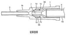
先行技術の血管外システムの例は、米国特許番号7,008,404号明細書に開示され、図1から図3に示される。留置カテーテルは、図1に示すように、中空のカテーテル本体1、カテーテル本体1の遠位端に設けられたホルダーlbに嵌合するカテーテル2、カテーテル本体1の内部に適合する隔壁3、および、カテーテル本体1の内部にスライド可能に適合する中空のプッシャー4を有する。カテーテル管2、隔壁3およびプッシャー4はこの順序で同軸状に位置合わせされる。 An example of a prior art extravascular system is disclosed in US Pat. No. 7,008,404 and shown in FIGS. As shown in FIG. 1, the indwelling catheter includes a
カテーテル本体1はチューブ状の形状を有する。カテーテル本体ルーメンの内面laは、遠位端に向かって、徐々に直径が減少するようにテーパが付けられている。カテーテル本体1は、内部を示して内部の動きをチェック可能にするために、好適には、透明または半透明な材料からなる。 カテーテル本体1に適当な材料は、これらに限定されないが、ポリカーボネート、ポリスチレン、ポリプロピレンなどの熱可塑性ポリマー樹脂を含む。 The
カテーテル2は、その近位端においてカテーテル本体1の内部と連通する管ホルダーlbに圧入される。皮膚を通して、または、血管への挿入により生じる抵抗を減らすために潤滑コーティングがカテーテル2の全部または一部に設けられることが好ましい。カテーテル2に適切な材料は、これらに限定されないが、フッ化エチレンプロピレン(FEP)、ポリ四フッ化エチレン(PTFE)、ポリウレタンなどの熱可塑性樹脂を含む。好適には、カテーテル2は、患者の身体が呈する生理学的条件への露出によって軟化する熱可塑性親水性ポリウレタンから形成される。 The
隔壁3は、近位端8を有する概ねチューブ状の形状および遠位端11に配置された平坦面を有する膜部9からなる。一般的には、隔壁3は、針先端5aを有する導入針5の隔壁3の貫通を容易にするために、膜部9を通って延在する、膜部9の中心付近に配置された単一の針スリット3aまたはバルブ開口をさらに含む。針スリット3aの反対側のスリット表面は、保管の間に導入針5の形状に密に適合し、その間のおよびその後の導入針5の取り外しによる流体の流出を防止し、導入針5の取り外しの際にシールするように設計される。プッシャー4が挿入されると、スリット3aは、遠位方向前方に拡大し、開口し、カテーテル本体1の後部とカテーテル2との間の流体連通を提供する。環状の突出部3bは、隔壁3の後部開口の内面に設けられ、近位方向のプッシャー4の動きを制限し、隔壁3からプッシャー4の転位を防止するためにプッシャー4の遠位端において肩4cに係合する。複数のギャップ3cは、隔壁3の外周囲とカテーテル本体1の内面1aの間で画定される。隔壁3により分割される遠位部および近位スペースは、ギャップ3cを通してお互いに連通する。従って、隔壁3はなめらかにスライドし、空気がギャップ3cを通過する。 The septum 3 comprises a membrane portion 9 having a generally tubular shape having a
プッシャー4は、一般的には、堅い熱可塑性材料等の材料から形成され、その内部を延在するルーメン7を有する。プッシャー4は、チューブ状部分4a、チューブ状部分4aの後部近位端と接続された円錐形のフランジ4b、および、チューブ状部分4aの外周囲から突出している肩4cを有する。従って、環状に形成された間隙は、カテーテル本体1のチューブ状部分4aと内面1aとの間で作成される。チューブ状部分4aの遠位先端部は、隔壁3のスリット3aの貫通を容易にするように、面取りをされ、隔壁3の環状の突出3bによりスライド可能に支持される。円錐形状フランジ4bは、針5の挿入を容易にするように、円錐形状内面を有する。フランジ4bの外周面は、カテーテル本体1の内面1aに接触し、プッシャー4に安定性を提供し、カテーテル2に対して同軸状の位置に維持する役割を果たす。しかしながら、フランジ4bの外周面は、内面1aとともに流体シールを形成しない。 The pusher 4 is generally formed from a material such as a rigid thermoplastic material and has a
留置カテーテルは、図1に示すような状態での使用のために、カテーテル2の前端から突出している針5の前端とともに、準備される。この状態において、針5は隔壁3を貫通し、その間に水密接続を提供し、それにより、血液漏れを防止する。 The indwelling catheter is prepared with the front end of the
この状態の留置カテーテルが患者の本体に挿入される。そして、図2に示すように、針5は、患者の身体に固定されている管2とともに取り除かれる。隔壁3は、針5の除去の際に、流体シールを維持し、これは環状の突出部1eとキャビティエッジ1dにより保持される。プッシャー4は、環状の突出3bおよび肩4cの相互作用によって近位位置に固定される。 The indwelling catheter in this state is inserted into the patient's body. Then, as shown in FIG. 2, the
そして、血管アクセス機器のコネクタ6 (例えば、ルアーコネクタ)は、カテーテル本体1の近位端から挿入される。カテーテル本体1に押し込まれると、コネクタ6はその遠位端おいてプッシャー4 を押圧する。従って、プッシャー4は、遠位方向の前方にスライドして、開口した隔壁3のスリット3a押圧し、それにより、開口位置に流れ制御バルブを起動させる。そして、隔壁3は、図3に示すように、遠位位置でプッシャー4の前方への動きが停止するカテーテル本体1のテーパが付いたキャビティ1cの内面に対して押圧されて、その結果、プッシャー4のルーメン7を介したカテーテル2と血管アクセス機器との間の連通を提供する。カテーテル本体1のテーパが付いた内面1aは、カテーテル本体1の近位端の外で流体漏れを防止するために、コネクタ6の円滑な挿入および圧入によるコネクタ6の外面6aおよび内面1aの密着を可能にする。 The connector 6 (for example, luer connector) of the vascular access device is inserted from the proximal end of the
しかしながら、このバルブメカニズムが流体流れおよびフラッシュ性能について問題を有することは言及されるべきである。第一に、流体流れは最もわずかな抵抗の経路に続き、図1から図3に示されるバルブメカニズムにおいては、大部分の流体流れがルーメン7のプッシャー4を通過することが、これが最も大きい開口をしている際に起こる。これは、バルブメカニズムを通過する安定した層流流れ(最小の流体乱れを有する)をもたらし、これは、ルーメン7の中心およびカテーテル本体1内のルーメンの中心において、最も高い程度の流れを生じさせ、カテーテル本体1のルーメンの周辺部において、最も低い程度の流れを生じさせる。従って、たとえば、隔壁3の遠位面の近くの、カテーテル本体1のテーパーを付けられたキャビティ1cの内面において、流れが低い又は流れの無い領域が生じ、これは、その後の、カテーテルの使用中にこの領域を流れる血液、薬剤または気泡の流出を困難にする。第二に、図1〜図3のバルブメカニズムは、カテーテル本体1内に小さな介在空間/領域を有し、これの中へ流体が使用中に流れ、流れが低い又は流れの無い領域を生じさせる。例えば、使用流体は、フランジ4bの外周面およびカテーテル本体1の内面1aとの間、および、チューブ状部分4aの外周と内面1aとの間の介在スペース98に流れる可能性がある。第三に、流体は、隔壁3の外周囲とカテーテル本体1の内面1aとの間のギャップ3cである介在スペース99に流入する可能性がある。スペース/エリア98,99に存在するいずれの流体も、(隔壁3により)本質的に閉じ込められる。というのは、これらの領域から流体がメインの流体流れに再復帰するためのたやすい流れの経路が存在しないからである。このことは、その後、カテーテルの使用の間に、これらの領域98および99に流入する可能性のあるいずれの血液、薬剤、または気泡の流出を非常に難しくする。 However, it should be mentioned that this valve mechanism has problems with fluid flow and flush performance. First, the fluid flow follows the path of least resistance, and in the valve mechanism shown in FIGS. 1 to 3, it is the largest opening that most fluid flow passes through the pusher 4 of the
フラッシュ特性を改善し、バルブメカニズムを有する血管アクセス機器内で生じる流れが低い又は流れの無い領域を生じさせる領域を排除又は削減する手段減少させる主題の発明のさまざまな実施形態にかかる複数のバルブメカニズムを図4〜図19に示す。 Multiple valve mechanisms according to various embodiments of the subject invention that improve flush characteristics and reduce means to eliminate or reduce regions that produce low or no flow regions in a vascular access device having a valve mechanism Are shown in FIGS.
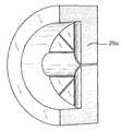
図4〜図6は、平衡流れプッシャー44の実施形態を示し、これは、プッシャー44の近位端を通過および近位端の周辺の流体流れを均一に等しくするために使用される。これは、フラッシュバック、吸引、採血からいかなる残余の血液をも除去するために、平衡化された流体流れ経路および好ましい流体の乱れを提供し、その結果、流れが低い又は流れの無い領域を生じさせる領域を削減する。 4-6 illustrate an embodiment of a
図4は、遠位端45と近位端46、および、その間で延在するルーメン47を有するプッシャー44を示す。フローポート48は、流路50を形成するために、縦方向に沿って延在し、プッシャー44の外面54のまわりに等しい間隔で配置されたリブ49とともに、プッシャー44の近位端46に配置される。入口ポート51は、流路50の遠位端に配置され、プッシャー44の側壁を通って延在する。図5は、近位位置のプッシャー44とともに、針の除去の後にカテーテル本体41のルーメン42の流体シールを形成する隔壁43を示す。図6は、遠位位置にあるプッシャー44を示しており、カテーテル本体41の近位端からの遠位方向に向けた流体の流れは、流路50に沿って、プッシャー44の近位端46の周囲52とルーメン42の内面53との間の4つのフローポート48によって方向転換され、円周ルーメン47のまわりに均等に分配された4つの入口ポート51を介してルーメン47へ戻る。隔壁43は、内面上にテーパ55を有し、これは、プッシャー44の外面54付近から入口ポート51へのクリアな流体流れ経路を提供するのに役立つ。従って、遠位方向においてプッシャー44の近位端46に接近する流体流れは、等しく分割され、流体は、入口ポート51を介してルーメン47に復帰する前に、プッシャー44のルーメン47の近位端46に侵入、あるいは、プッシャー44の外面54付近を流れる等しい可能性を有する。従って、このバルブメカニズムのフラッシュ特性は、プッシャー44の外面54とルーメン42の内面53との間の介在スペース56に高い流体流れがあるので、図1〜図3に示したバルブメカニズムのフラッシュ特性より優れている。さらに、乱流が、入口ポート51からの流体の流れの合流位置でルーメン47内に形成される。 FIG. 4 shows a
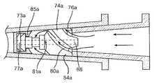
図7〜図9は、本発明の別の実施形態を示し、これは、完全なフラッシュを促すようにプッシャーの外部周辺でらせん状の流れ経路の使用により異なる図4〜図6に示したものと同様なバルブメカニズムを有する。図7は、遠位端75および近位端76と、その間で延在するルーメン77とを有するプッシャー74を示す。リブ79は、プッシャー74の近位端76から始まり、らせん状に延在し、プッシャー74の外面54の周囲に等しい間隔で配置され、流路80を形成する。入口ポート81は、らせん状の流路80の遠位端に配置され、プッシャー74の側壁を通って延在する。図7〜図9は、遠位位置のプッシャー74を示し、流体がプッシャー74のルーメン77を介して、または、プッシャー44の外面54のらせん状のチャンネル80を通じてのいずれかで流れうる。 カテーテル本体41の近位端からの遠位方向に流れる流体は、プッシャー74の近位端76において、らせん状の流路に入り、流路80に沿って流れ、円周ルーメン77のまわりに等しく分配された4つの入口ポート81によりルーメン77へ戻る。隔壁73もまた、介在スペースを最小に保持するために、プッシャー74の外面54のまわりの対応するテーパ87と結合する、テーパ85を内面上に有することができる。らせん状の流路の使用は、直線状の長手方向の流路を持つ同じ設計のプッシャーの場合と比べて、より速い流速およびより強い乱流を生じさせる。 7-9 illustrate another embodiment of the present invention, which is illustrated in FIGS. 4-6, which differs by the use of a helical flow path around the exterior of the pusher to facilitate complete flushing. Has the same valve mechanism. FIG. 7 shows a
図10は、図7〜図9に示した実施形態と同様に、プッシャー74aの外面84a上にらせん状の流路80aをもつバルブメカニズムの別の実施形態を示す。しかしながら、ルーメン77aを通じて流体流れを制限または防止し、らせん状の流路80aを通じた流体流れの大部分を方向転換するために、導入針の除去の際に、プッシャー74aの近位端76aにおいて、ヒンジ式の流れデフレクター88が展開される。さらに、2つの入口ポート81aが存在し、これらの各々は、らせん状の流路80aの遠位端に配置されたルーメン77aの円周の約4分の1である。さらに、隔壁73aは、入口ポート81aへの直接の流体流れを助けるために、内側近位面にフレアー状の面85aを有する。 FIG. 10 shows another embodiment of a valve mechanism having a
図11は、らせん状のまたは渦巻状の流路をもつバルブメカニズムのさらなる実施形態を示す。これは、隔壁を含むだけで、プッシャーを使わない一体のバルブメカニズムである。このバルブメカニズムにおける唯一の流体の経路は、隔壁103の外面105のらせん状の流路104であり、これは、空気が逃げるのを許容し、最小限の血液が逃げること許容し、そして、注入が起こることを可能にする。スリット109は、 導入針の挿入を容易にするように、隔壁を通って延在しているが、導入針の除去の後に流体シールを形成する。隔壁103は、カテーテル本体ルーメン102のテーパ106および環状の突出107の組み合わせによって定位置に保持される。なお、図7〜図9の実施形態に示すように、らせん状の流路104の全断面積は、ルーメン77およびらせん状の流路80の合わせた断面積と実質的に等しくなければならない。これは、重要な流れの制限または圧力上昇を防止するために、総流体流れ断面積が十分に大きくなければならないからである。 FIG. 11 shows a further embodiment of a valve mechanism having a spiral or spiral channel. This is an integral valve mechanism that only includes a septum and does not use a pusher. The only fluid path in this valve mechanism is the
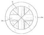
図12および図13は、バルブメカニズムの実施形態を示し、これは、プッシャー24の外面34上のリブ29の存在が、平行な同軸状の流体流れがルーメン27を通じて、および、プッシャー24の外面34と隔壁23との間の双方で生じることを可能にする。図13は、遠位端25および近位端26と、その間で延在するルーメン27を有する図12のプッシャー24を示す。リブ29は、流路30を形成するために、プッシャー24の遠位端25から出て、プッシャー24の外面34のまわりに等しい間隔をおいて延在し、近位端26を通過してルアーコネクタ39に作用する接触ポイントを提供するように連続する。隔壁23は、遠位位置に到達すると、プッシャー24の遠位端25にリブ29により曲げられる。従って、リブ29によって、半径方向のシールが、プッシャー24と隔壁23の外面34との間で形成されるのを防ぎ、その結果、流体が隔壁23を過ぎて流路30に沿ってだけでなく、プッシャー24のルーメン27を通って流れることができる。12 and 13 show an embodiment of the valve mechanism, which is the presence of
図14および図15は、プッシャーの外面の代わりにリブ29aが隔壁23aの膜部31の近位面にある図11〜図13のバルブメカニズムの代替の実施形態を示す。 14 and 15 show an alternative embodiment of the valve mechanism of FIGS. 11-13 in which the
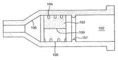
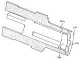
図16〜図18は、バルブメカニズムの実施形態を示し、これは、プッシャーデザインの開放性および隔壁の配向の逆転により、高いフラッシュ性能を与える。プッシャー114は、ルアーコネクタ119とルーメン117との間のスペーサーとして作用するリブ132を含み、ルアーコネクタ119の先端から流体が広がるための十分な軸線方向の長さを提供し、プッシャー114とカテーテル本体111の内壁123との間のスペース126を通る流れの大部分を方向付ける。プッシャー114の側壁130を通る穿孔{せんこう}または長手方向のスロット121は、流れる流体がプッシャー114のルーメン117に再侵入しつつ、プッシャー114が(図18に示すような)遠位位置にある時に、隔壁113を迂回することを許容し、そして、下流遠位側の隔壁113をクリーンにするためにプッシャー114から還流させることを可能にする。リブ132は、近位位置にプッシャー114を保持するためカテーテル本体111の内側壁113の下方の切れ込み131と、プッシャー114を遠位位置に保持するため隔壁113と相互作用する。隔壁113は、典型的な隔壁として、概ねチューブ状形状からなり、遠位端133の代わりに近位端134に配置されたシール膜部119を有する。隔壁113がプッシャー114の遠位端135を取り囲んでいないので、膜部のこの逆の配向は、制限の少ない流れ経路を提供する。 FIGS. 16-18 show an embodiment of the valve mechanism, which provides high flush performance due to the openness of the pusher design and reversal of the partition orientation. The
図19は、バルブメカニズムのさらなる実施形態を示し、これは、プッシャー114aの遠位端へエラストマーのストッパー141を内蔵し、針が除去された後にルーメン117aに流れ制限を与え、流れる流体の一部をプッシャー114aの外に強制的に押しやり、血液または注入物を清浄する。ルーメン117a内およびプッシャー114a外の相対的な流速のバランスは、ストッパー141に穴142を付加し、その穴142のサイズ、あるいは、ストッパー141によるルーメン117aの閉塞程度によってコントロールできる。 FIG. 19 shows a further embodiment of the valve mechanism, which incorporates an
本明細書で記述されたいずれの隔壁でも、必要な場合に、特定の血液漏洩速度を生み出すように寸法付けされた膜部の中心に存在する穴を持つことができ、各種の適切な材料および各種の適切な製造法を通じて製造できる。例えば、隔壁は、液状シリコーンゴムから、インサート成形、射出成形、他の成形技術、あるいは成形技術の組み合わせなどの適当な成形方法により形成できる。
隔壁103、または、本明細書で記述されたいずれの隔壁でも、その表面のいずれか、特に流体との接触を有する表面に抗菌物質のコーティングを含んでもよい。Any septum described herein can have a hole in the center of the membrane section that is dimensioned to produce a specific blood leak rate, if required, with a variety of suitable materials and It can be manufactured through various suitable manufacturing methods. For example, the partition walls can be formed from a liquid silicone rubber by an appropriate molding method such as insert molding, injection molding, other molding techniques, or a combination of molding techniques.
The
本発明の説明を助ける実施形態は、本明細書において実施例に関連付けて説明されたけれども、本発明はこれらの明確な実施形態に制限されず、様々な他の変更および修正が本発明の範囲または精神を逸脱せずに当業者によってなされてもよいことが理解されるべきである。 While embodiments that aid in the description of the invention have been described herein with reference to examples, the invention is not limited to these specific embodiments and various other changes and modifications are within the scope of the invention. Or it should be understood that it may be made by those skilled in the art without departing from the spirit.
Claims (10)
Translated fromJapanese前記第1のルーメン内に配置され、前記第1のルーメンを遠位部分と近位部分とに隔てる隔壁と、
前記第1のルーメンの近位部分内に配置され、外表面と、遠位端と、近位端と、および、前記遠位端と近位端との間で延在する第2のルーメンを有するプッシャーと、を有し、
前記外表面は、前記プッシャーの遠位端から出て当該外表面に沿って延在し、当該プッシャーの近位端を通り越すリブをさらに有し、前記リブの近位端は、接触ポイントを備え、
前記静脈内のカテーテルアダプターの内面と前記プッシャーの外表面との間に形成された第1の流路を有し、
前記第2のルーメンを有する第2の流路を有する、
血管アクセス機器。An inner surface,a proximal end,a distal end, and a catheter adapter ofthe intravenous having a first lumen extending betweenthe proximal and distal ends,
A septum disposed within the first lumen and separating the first lumen into a distal portion and a proximal portion;
A second lumen disposed within a proximal portion of the first lumenand extendingbetween anouter surface, a distal end, a proximal end, and thedistal end and the proximal end ;Having a pusher,
The outer surface further includes a rib extending from the distal end of the pusher and extending along the outer surface and past the proximal end of the pusher, the proximal end of the rib comprising a contact point. ,
A first flow path formed between the inner surface of the catheter adapter in the vein and the outer surface of the pusher;
Having a second flow path having the second lumen;
Vascular access equipment.
前記ルーメン内に配置された隔壁と、を有し、
前記隔壁は、前記ルーメンを前記遠位部分および近位部分に分割し、
前記隔壁の外表面は、前記ルーメンの遠位部分と近位部分との間に流体連通を提供するらせん状の溝を有する、血管アクセス機器。An intravenous catheter adapter having an inner surface, a proximal end, a distal end, and a first lumen extending between the proximal end and the distal end;
A partition disposed within the lumen,
The septum divides the lumen into the distal and proximal portions;
The vascular access device, wherein the outer surface of the septum has a helical groove that provides fluid communication between the distal and proximal portions of the lumen .
前記本体は、隔壁およびプッシャーを備える流れ制御バルブを含み、
前記プッシャーは、遠位端、近位端、外表面、内部を通る第2のルーメン、および、少なくとも一の流路を有し、
流体が、等しい確率で、前記プッシャーの前記近位端において前記第2のルーメン内、および、前記少なくとも一の流路中を流れ、
前記第1および第2のルーメンは、流体が前記第1のルーメンに沿って流れ、前記第2のルーメンとは独立に前記隔壁を迂回するように、同軸状に配向されている、
血管アクセス機器。Comprising a body having a first lumen extending through the interior;
The body includes a flow control valve comprising a septum and a pusher;
The pusher has a distal end, a proximal end, an outer surface, a second lumen passing through the interior, and at least one flow path;
Fluid flows with equal probability in the second lumen at the proximal end of the pusher and in the at least one flow path;
The first and second lumens are coaxially oriented such that fluid flows along the first lumen and bypasses the septum independently of the second lumen;
Vascular access equipment.
Applications Claiming Priority (5)
| Application Number | Priority Date | Filing Date | Title |
|---|---|---|---|
| US15177309P | 2009-02-11 | 2009-02-11 | |
| US61/151,773 | 2009-02-11 | ||
| US12/703,406US8361038B2 (en) | 2009-02-11 | 2010-02-10 | Systems and methods for providing a flow control valve for a medical device |
| US12/703,406 | 2010-02-10 | ||
| PCT/US2010/023899WO2010093792A1 (en) | 2009-02-11 | 2010-02-11 | Systems and methods for providing a flow control valve for a medical device |
Publications (2)
| Publication Number | Publication Date |
|---|---|
| JP2012517327A JP2012517327A (en) | 2012-08-02 |
| JP5591833B2true JP5591833B2 (en) | 2014-09-17 |
Family
ID=42541015
Family Applications (1)
| Application Number | Title | Priority Date | Filing Date |
|---|---|---|---|
| JP2011550230AActiveJP5591833B2 (en) | 2009-02-11 | 2010-02-11 | System and method for providing a flow control valve for a medical device |
Country Status (9)
| Country | Link |
|---|---|
| US (2) | US8361038B2 (en) |
| EP (1) | EP2398545B1 (en) |
| JP (1) | JP5591833B2 (en) |
| CN (1) | CN102355922B (en) |
| AU (1) | AU2010213699B2 (en) |
| BR (1) | BRPI1008371B1 (en) |
| CA (1) | CA2752024C (en) |
| ES (1) | ES2541703T3 (en) |
| WO (1) | WO2010093792A1 (en) |
Cited By (1)
| Publication number | Priority date | Publication date | Assignee | Title |
|---|---|---|---|---|
| US12415055B2 (en) | 2017-09-29 | 2025-09-16 | Terumo Kabushiki Kaisha | Catheter assembly and medical valve |
Families Citing this family (56)
| Publication number | Priority date | Publication date | Assignee | Title |
|---|---|---|---|---|
| EP1907042B1 (en) | 2005-07-06 | 2009-03-11 | Vascular Pathways Inc. | Intravenous catheter insertion device and method of use |
| EP2150304B1 (en) | 2007-05-07 | 2010-12-01 | Vascular Pathways Inc. | Intravenous catheter insertion and blood sample devices and method of use |
| US8361038B2 (en)* | 2009-02-11 | 2013-01-29 | Becton, Dickinson And Company | Systems and methods for providing a flow control valve for a medical device |
| US8881768B2 (en) | 2009-05-27 | 2014-11-11 | Flowserve Management Company | Fluid flow control devices and systems, and methods of flowing fluids therethrough |
| US9950139B2 (en) | 2010-05-14 | 2018-04-24 | C. R. Bard, Inc. | Catheter placement device including guidewire and catheter control elements |
| US9872971B2 (en) | 2010-05-14 | 2018-01-23 | C. R. Bard, Inc. | Guidewire extension system for a catheter placement device |
| US11925779B2 (en) | 2010-05-14 | 2024-03-12 | C. R. Bard, Inc. | Catheter insertion device including top-mounted advancement components |
| US8932258B2 (en) | 2010-05-14 | 2015-01-13 | C. R. Bard, Inc. | Catheter placement device and method |
| US10384039B2 (en) | 2010-05-14 | 2019-08-20 | C. R. Bard, Inc. | Catheter insertion device including top-mounted advancement components |
| US9545495B2 (en) | 2010-06-25 | 2017-01-17 | Smiths Medical Asd, Inc. | Catheter assembly with seal member |
| US8652104B2 (en) | 2010-06-25 | 2014-02-18 | Smiths Medical Asd, Inc. | Catheter assembly with seal member |
| DE112011102149T5 (en)* | 2010-06-25 | 2013-05-02 | B. Braun Melsungen Ag | Retaining element and its application |
| US8690833B2 (en) | 2011-01-31 | 2014-04-08 | Vascular Pathways, Inc. | Intravenous catheter and insertion device with reduced blood spatter |
| ES2835652T3 (en) | 2011-02-25 | 2021-06-22 | Bard Inc C R | Medical component insertion device including a retractable needle |
| WO2012113865A1 (en)* | 2011-02-25 | 2012-08-30 | B. Braun Melsungen Ag | Flushing medical devices |
| USD903101S1 (en) | 2011-05-13 | 2020-11-24 | C. R. Bard, Inc. | Catheter |
| JP6278335B2 (en) | 2011-10-05 | 2018-02-14 | ニプロ株式会社 | Indwelling catheter |
| US9566413B2 (en)* | 2012-03-23 | 2017-02-14 | Terumo Medical Corporation | Dilator centering device and assemblies |
| US20140264132A1 (en)* | 2013-03-15 | 2014-09-18 | Flowserve Management Company | Fluid flow control devices and systems, and methods of flowing fluids therethrough |
| US10500376B2 (en) | 2013-06-07 | 2019-12-10 | Becton, Dickinson And Company | IV catheter having external needle shield and internal blood control septum |
| US9775972B2 (en) | 2013-07-30 | 2017-10-03 | Becton, Dickinson And Company | Interlocking needle hub and catheter hub actuator to increase rigidity of IV catheter assembly |
| EP2862587A1 (en) | 2013-10-15 | 2015-04-22 | Becton Dickinson France | Tip cap assembly for closing an injection system |
| US9919136B2 (en)* | 2013-12-04 | 2018-03-20 | B. Braun Melsungen Ag | Catheter assembly with reusable valve |
| CN104922748A (en) | 2014-01-08 | 2015-09-23 | B.布劳恩梅尔松根股份公司 | Catheter Assemblies With Valves And Related Methods |
| CA2943721C (en)* | 2014-03-26 | 2021-06-08 | L.O.M. Laboratories Inc. | Gas release cell |
| SG11201608547XA (en) | 2014-04-18 | 2016-11-29 | Becton Dickinson Co | Needle capture safety interlock for catheter |
| WO2016037127A1 (en) | 2014-09-05 | 2016-03-10 | C.R. Bard, Inc. | Catheter insertion device including retractable needle |
| US11511052B2 (en) | 2014-11-10 | 2022-11-29 | Becton, Dickinson And Company | Safety IV catheter with V-clip interlock and needle tip capture |
| KR102569203B1 (en) | 2015-04-17 | 2023-08-22 | 백톤 디킨슨 앤드 컴퍼니 | Versatile blood control safety catheter assembly |
| USD903100S1 (en) | 2015-05-01 | 2020-11-24 | C. R. Bard, Inc. | Catheter placement device |
| US10449331B2 (en)* | 2015-05-13 | 2019-10-22 | B. Braun Melsungen Ag | Catheter devices with seals and related methods |
| CN113350614A (en) | 2015-05-15 | 2021-09-07 | C·R·巴德股份有限公司 | Catheter placement device including extendable needle safety feature |
| EP3552652B2 (en) | 2015-08-18 | 2024-07-03 | B. Braun Melsungen AG | Catheter devices with valves |
| CN109069732B (en) | 2016-02-22 | 2021-09-14 | L2R企业有限责任公司 | Microfluidic flow restrictor assembly and method of making same |
| US11344220B2 (en) | 2016-05-13 | 2022-05-31 | Becton, Dickinson And Company | Invasive medical device cover with magnet |
| EP3495016B1 (en)* | 2016-08-04 | 2025-10-01 | Nipro Corporation | Valved needle assembly |
| US10032552B2 (en)* | 2016-08-30 | 2018-07-24 | Becton, Dickinson And Company | Cover for tissue penetrating device with integrated magnets and magnetic shielding |
| US10493262B2 (en)* | 2016-09-12 | 2019-12-03 | C. R. Bard, Inc. | Blood control for a catheter insertion device |
| EP3585471B1 (en) | 2017-03-01 | 2025-01-01 | C. R. Bard, Inc. | Catheter insertion device |
| JP6889820B2 (en)* | 2017-07-21 | 2021-06-18 | 株式会社トップ | Indwelling needle assembly |
| CN116328070A (en)* | 2017-09-12 | 2023-06-27 | 东莞科威医疗器械有限公司 | A spiral diversion integrated membrane oxygenator |
| CN107432960B (en)* | 2017-09-12 | 2024-01-09 | 东莞科威医疗器械有限公司 | Spiral diversion integrated film type oxygenator |
| JP7053978B2 (en)* | 2017-11-09 | 2022-04-13 | 株式会社トップ | Indwelling needle |
| JP6978658B2 (en)* | 2017-11-17 | 2021-12-08 | 株式会社トップ | Indwelling needle |
| ES2980192T3 (en) | 2018-03-07 | 2024-09-30 | Bard Access Systems Inc | Guidewire advancement and blood reflux systems for a medical device insertion system |
| MY185708A (en)* | 2018-05-14 | 2021-05-31 | Kim Seng @ Chong Kim Sang Chong | Catheter valve |
| JP7091593B2 (en)* | 2018-07-25 | 2022-06-28 | 株式会社トップ | Indwelling needle assembly |
| USD921884S1 (en) | 2018-07-27 | 2021-06-08 | Bard Access Systems, Inc. | Catheter insertion device |
| WO2020127328A1 (en) | 2018-12-17 | 2020-06-25 | B. Braun Melsungen Ag | Over-the-needle catheter assemblies and related manufacturing method |
| WO2020189466A1 (en)* | 2019-03-18 | 2020-09-24 | テルモ株式会社 | Catheter assembly |
| CA3151126A1 (en) | 2019-08-19 | 2021-02-25 | Becton, Dickinson And Company | Midline catheter placement device |
| US11872360B2 (en)* | 2019-11-11 | 2024-01-16 | Becton, Dickinson And Company | Catheter systems and methods for flashback visualization at various blood pressures |
| FR3105004B1 (en)* | 2019-12-18 | 2023-10-27 | Univ Bordeaux | CATHETER FOR ADMINISTRATION OF A DRUG SPRAY INTO THE TRACHEA OF A SUBJECT |
| EP4188480A1 (en)* | 2020-07-29 | 2023-06-07 | Tessen Solutions Limited | Infusion apparatus |
| JP2025041996A (en)* | 2022-02-25 | 2025-03-27 | テルモ株式会社 | Catheter Assembly |
| WO2025017556A1 (en)* | 2023-07-19 | 2025-01-23 | Bullpup Scientific Ltd. | Method and apparatus for inserting a catheter tube |
Family Cites Families (72)
| Publication number | Priority date | Publication date | Assignee | Title |
|---|---|---|---|---|
| DE2817102C2 (en)* | 1978-04-19 | 1985-01-24 | Dr. Eduard Fresenius, Chemisch-pharmazeutische Industrie KG, 6380 Bad Homburg | Connector for plastic cannulas or venous catheters |
| US4449693A (en)* | 1982-09-30 | 1984-05-22 | Gereg Gordon A | Catheter check valve |
| GB8527646D0 (en)* | 1985-11-08 | 1985-12-11 | Cox J A | Devices for sampling drainage |
| GB8627808D0 (en)* | 1986-11-20 | 1986-12-17 | Cox J A | Sampling liquids from human/animal body |
| US4842591A (en)* | 1988-01-21 | 1989-06-27 | Luther Ronald B | Connector with one-way septum valve, and assembly |
| DE3809127C1 (en)* | 1988-03-18 | 1989-04-13 | B. Braun Melsungen Ag, 3508 Melsungen, De | |
| US4874377A (en)* | 1988-05-26 | 1989-10-17 | Davis Newgard Revocable Family Living Trust | Self-occluding intravascular cannula assembly |
| US5064416A (en)* | 1988-05-26 | 1991-11-12 | Newgard Kent W | Self-occluding intravascular cannula assembly |
| US4950257A (en)* | 1988-09-15 | 1990-08-21 | Mallinckrodt, Inc. | Catheter introducer with flexible tip |
| US5053014A (en)* | 1990-02-01 | 1991-10-01 | Critikon, Inc. | Catheter with controlled valve |
| US5041097A (en)* | 1990-02-26 | 1991-08-20 | Johnson Gerald W | Intravenous catheter fitting with protective end seal |
| US5062836A (en)* | 1990-03-14 | 1991-11-05 | The Kendall Company | Placement device for a catheter and guide wire |
| US5084023A (en)* | 1990-03-22 | 1992-01-28 | Critikon, Inc. | Bloodless catheter with self-shielding needle |
| US5108374A (en)* | 1990-05-02 | 1992-04-28 | Critikon, Inc. | Stickless catheter with manual shut-off valve |
| US5127905A (en)* | 1990-05-02 | 1992-07-07 | Critikon, Inc. | Stickless catheter with manual shut-off valve |
| US5085645A (en)* | 1990-08-15 | 1992-02-04 | Becton, Dickinson And Company | Apparatus and method for a catheter adapter with valve |
| US5154703A (en)* | 1990-10-30 | 1992-10-13 | Care Medical Devices, Inc. | Bloodless catheter |
| US5290246A (en)* | 1991-01-18 | 1994-03-01 | Terumo Kabushiki Kaisha | Piercing needle |
| US5156596A (en)* | 1991-02-04 | 1992-10-20 | Menlo Care, Inc. | Catheter with changeable number of lumens |
| US5295969A (en)* | 1992-04-27 | 1994-03-22 | Cathco, Inc. | Vascular access device with air-tight blood containment capability |
| US5234410A (en)* | 1992-10-23 | 1993-08-10 | Vlv Associates | Catheter assembly |
| US5330435A (en)* | 1993-04-08 | 1994-07-19 | Vaillancourt Vincent L | Valve for a catheter assembly |
| DE4311715C2 (en)* | 1993-04-08 | 1996-02-01 | Fresenius Ag | Port cannula |
| US5350363A (en)* | 1993-06-14 | 1994-09-27 | Cordis Corporation | Enhanced sheath valve |
| US5657963A (en)* | 1993-06-16 | 1997-08-19 | United States Surgical Corporation | Seal assembly for accommodating introduction of surgical instruments |
| US5352205A (en)* | 1993-09-16 | 1994-10-04 | Lawrence Dales | Bloodless insertion catheter assembly |
| JP2584597B2 (en) | 1993-09-29 | 1997-02-26 | ベクトン・ディッキンソン・アンド・カンパニー | Catheter introduction device with blood seal |
| US5806831A (en)* | 1993-10-13 | 1998-09-15 | Paradis; Joseph R. | Control of fluid flow with internal cannula |
| US5549577A (en)* | 1993-12-29 | 1996-08-27 | Ivac Corporation | Needleless connector |
| US5522804A (en)* | 1994-02-15 | 1996-06-04 | Lynn; Lawrence A. | Aspiration, mixing, and injection syringe |
| US5405323A (en)* | 1994-02-22 | 1995-04-11 | Aeroquip Corporation | Catheter check valve assembly |
| US5487728A (en)* | 1994-05-19 | 1996-01-30 | Vaillancourt; Vincent L. | Connector assembly |
| US5549566A (en)* | 1994-10-27 | 1996-08-27 | Abbott Laboratories | Valved intravenous fluid line infusion device |
| DE4442352C1 (en)* | 1994-11-29 | 1995-12-21 | Braun Melsungen Ag | Valve arrangement provided in connector for use e.g. with cannula |
| US5520666A (en)* | 1994-12-06 | 1996-05-28 | Abbott Laboratories | Valved intravenous fluid line connector |
| US5575769A (en)* | 1995-05-30 | 1996-11-19 | Vaillancourt; Vincent L. | Cannula for a slit septum and a lock arrangement therefore |
| IT1285266B1 (en)* | 1996-02-26 | 1998-06-03 | Borla Ind | CONNECTOR WITH PROTECTION VALVE FOR INFUSION / TRANSFUSION AND SIMILAR MEDICAL LINES. |
| US5817069A (en)* | 1996-02-28 | 1998-10-06 | Vadus, Inc. | Valve assembly |
| US5651772A (en)* | 1996-02-28 | 1997-07-29 | Aeroquip Corporation | Needle guard assembly |
| US6273869B1 (en)* | 1996-06-13 | 2001-08-14 | Vincent L. Vaillancourt | Valve connector |
| US5738144A (en)* | 1996-10-11 | 1998-04-14 | Aeroquip Corporation | Luer connecting coupling |
| PT952868E (en)* | 1996-11-18 | 2004-08-31 | Nypro Inc | VALVE CONICA-LUER LAVAVEL |
| US6883778B1 (en)* | 1996-11-18 | 2005-04-26 | Nypro Inc. | Apparatus for reducing fluid drawback through a medical valve |
| US5954698A (en)* | 1997-01-08 | 1999-09-21 | Vadus, Inc. | Catheter apparatus having valved catheter hub and needle protector |
| US5967490A (en)* | 1997-01-08 | 1999-10-19 | Vadus, Inc. | Catheter hubs having a valve |
| US5911710A (en)* | 1997-05-02 | 1999-06-15 | Schneider/Namic | Medical insertion device with hemostatic valve |
| US6117108A (en)* | 1997-08-20 | 2000-09-12 | Braun Melsungen Ag | Spring clip safety IV catheter |
| US6077244A (en)* | 1998-04-30 | 2000-06-20 | Mdc Investment Holdings, Inc. | Catheter insertion device with retractable needle |
| NL1007997C2 (en) | 1998-01-09 | 1999-07-12 | Cordis Europ | Device for inserting an elongated medical device. |
| WO1999061093A1 (en)* | 1998-05-29 | 1999-12-02 | Lynn Lawrence A | Luer receiver and method for fluid transfer |
| US6331176B1 (en)* | 1999-03-11 | 2001-12-18 | Advanced Cardiovascular Systems, Inc. | Bleed back control assembly and method |
| EP1218045B1 (en)* | 1999-08-12 | 2017-12-13 | Lawrence A. Lynn | Luer receiving vascular access system |
| FR2802432B1 (en)* | 1999-12-16 | 2002-03-08 | Vygon | AUTOMATIC SHUTTER CONNECTOR FOR CONNECTING A LIQUID INJECTION HEAD TO AN INJECTION OUTPUT |
| US6699221B2 (en)* | 2000-06-15 | 2004-03-02 | Vincent L. Vaillancourt | Bloodless catheter |
| JP4996015B2 (en)* | 2001-03-12 | 2012-08-08 | メディキット株式会社 | Indwelling catheter |
| US6506181B2 (en)* | 2001-05-25 | 2003-01-14 | Becton, Dickinson And Company | Catheter having a low drag septum |
| JP3808806B2 (en)* | 2002-06-26 | 2006-08-16 | メディキット株式会社 | Indwelling needle |
| DE20210394U1 (en)* | 2002-07-04 | 2002-09-12 | B. Braun Melsungen Ag, 34212 Melsungen | catheter introducer |
| US7347839B2 (en)* | 2003-02-12 | 2008-03-25 | Nipro Corporation | Indwelling catheter |
| WO2004112866A2 (en)* | 2003-06-17 | 2004-12-29 | Filtertek Inc. | Fluid handling device and method of making same |
| US7470254B2 (en)* | 2003-08-18 | 2008-12-30 | Medical Components, Inc. | Needle with sealing valve |
| US7608082B2 (en) | 2005-01-06 | 2009-10-27 | Tyco Healthcare Group Lp | Surgical seal for use in a surgical access apparatus |
| US20070083162A1 (en)* | 2005-10-11 | 2007-04-12 | Span-America Medical Systems, Inc. | Valve for intravenous catheter |
| US7695458B2 (en)* | 2005-10-11 | 2010-04-13 | Tyco Healthcare Group Lp | IV catheter with in-line valve and methods related thereto |
| ES2714385T3 (en)* | 2006-03-01 | 2019-05-28 | Becton Dickinson Co | Controlled return for vascular access devices |
| US8308691B2 (en) | 2006-11-03 | 2012-11-13 | B. Braun Melsungen Ag | Catheter assembly and components thereof |
| JP2008043445A (en)* | 2006-08-11 | 2008-02-28 | Medikit Kk | Catheter, hollow needle and dwelling needle assembly |
| US8202251B2 (en) | 2008-03-14 | 2012-06-19 | Access Scientific, Inc. | Access device |
| US8469928B2 (en) | 2009-02-11 | 2013-06-25 | Becton, Dickinson And Company | Systems and methods for providing a flushable catheter assembly |
| US8361038B2 (en)* | 2009-02-11 | 2013-01-29 | Becton, Dickinson And Company | Systems and methods for providing a flow control valve for a medical device |
| US8496623B2 (en)* | 2009-03-02 | 2013-07-30 | Becton, Dickinson And Company | Bi-directional cannula feature capture mechanism |
| DE202009009602U1 (en) | 2009-07-15 | 2009-12-10 | B. Braun Melsungen Ag | Catheter device with needle guard |
- 2010
- 2010-02-10USUS12/703,406patent/US8361038B2/enactiveActive
- 2010-02-11CACA2752024Apatent/CA2752024C/enactiveActive
- 2010-02-11EPEP10705480.1Apatent/EP2398545B1/enactiveActive
- 2010-02-11CNCN201080012092.5Apatent/CN102355922B/enactiveActive
- 2010-02-11JPJP2011550230Apatent/JP5591833B2/enactiveActive
- 2010-02-11WOPCT/US2010/023899patent/WO2010093792A1/enactiveApplication Filing
- 2010-02-11AUAU2010213699Apatent/AU2010213699B2/enactiveActive
- 2010-02-11BRBRPI1008371-5Apatent/BRPI1008371B1/enactiveIP Right Grant
- 2010-02-11ESES10705480.1Tpatent/ES2541703T3/enactiveActive
- 2012
- 2012-12-20USUS13/722,733patent/US8740859B2/enactiveActive
Cited By (1)
| Publication number | Priority date | Publication date | Assignee | Title |
|---|---|---|---|---|
| US12415055B2 (en) | 2017-09-29 | 2025-09-16 | Terumo Kabushiki Kaisha | Catheter assembly and medical valve |
Also Published As
| Publication number | Publication date |
|---|---|
| AU2010213699A1 (en) | 2011-08-25 |
| WO2010093792A1 (en) | 2010-08-19 |
| EP2398545A1 (en) | 2011-12-28 |
| US20130110055A1 (en) | 2013-05-02 |
| ES2541703T3 (en) | 2015-07-23 |
| BRPI1008371B1 (en) | 2019-10-08 |
| US8361038B2 (en) | 2013-01-29 |
| US20100204660A1 (en) | 2010-08-12 |
| AU2010213699B2 (en) | 2015-09-24 |
| JP2012517327A (en) | 2012-08-02 |
| CN102355922B (en) | 2014-07-02 |
| US8740859B2 (en) | 2014-06-03 |
| EP2398545B1 (en) | 2015-04-08 |
| CA2752024C (en) | 2017-05-23 |
| CA2752024A1 (en) | 2010-08-19 |
| BRPI1008371A2 (en) | 2018-03-06 |
| CN102355922A (en) | 2012-02-15 |
Similar Documents
| Publication | Publication Date | Title |
|---|---|---|
| JP5591833B2 (en) | System and method for providing a flow control valve for a medical device | |
| AU2018202356B2 (en) | Systems and methods for providing a flushable catheter assembly | |
| CN103200985B (en) | Systems and methods for providing flushable catheter assemblies | |
| RU2742869C2 (en) | Intravenous catheter with safety function and pressure controlled valve element | |
| CN103476450B (en) | Systems and methods for providing catheter assemblies |
Legal Events
| Date | Code | Title | Description |
|---|---|---|---|
| A621 | Written request for application examination | Free format text:JAPANESE INTERMEDIATE CODE: A621 Effective date:20130208 | |
| A131 | Notification of reasons for refusal | Free format text:JAPANESE INTERMEDIATE CODE: A131 Effective date:20131210 | |
| A977 | Report on retrieval | Free format text:JAPANESE INTERMEDIATE CODE: A971007 Effective date:20131213 | |
| A521 | Request for written amendment filed | Free format text:JAPANESE INTERMEDIATE CODE: A523 Effective date:20140310 | |
| TRDD | Decision of grant or rejection written | ||
| A01 | Written decision to grant a patent or to grant a registration (utility model) | Free format text:JAPANESE INTERMEDIATE CODE: A01 Effective date:20140701 | |
| A61 | First payment of annual fees (during grant procedure) | Free format text:JAPANESE INTERMEDIATE CODE: A61 Effective date:20140730 | |
| R150 | Certificate of patent or registration of utility model | Ref document number:5591833 Country of ref document:JP Free format text:JAPANESE INTERMEDIATE CODE: R150 | |
| R250 | Receipt of annual fees | Free format text:JAPANESE INTERMEDIATE CODE: R250 | |
| R250 | Receipt of annual fees | Free format text:JAPANESE INTERMEDIATE CODE: R250 | |
| R250 | Receipt of annual fees | Free format text:JAPANESE INTERMEDIATE CODE: R250 | |
| R250 | Receipt of annual fees | Free format text:JAPANESE INTERMEDIATE CODE: R250 | |
| R250 | Receipt of annual fees | Free format text:JAPANESE INTERMEDIATE CODE: R250 | |
| R250 | Receipt of annual fees | Free format text:JAPANESE INTERMEDIATE CODE: R250 | |
| R250 | Receipt of annual fees | Free format text:JAPANESE INTERMEDIATE CODE: R250 |