JP5591213B2 - Inverter device and air conditioner equipped with the same - Google Patents
Inverter device and air conditioner equipped with the sameDownload PDFInfo
- Publication number
- JP5591213B2 JP5591213B2JP2011257386AJP2011257386AJP5591213B2JP 5591213 B2JP5591213 B2JP 5591213B2JP 2011257386 AJP2011257386 AJP 2011257386AJP 2011257386 AJP2011257386 AJP 2011257386AJP 5591213 B2JP5591213 B2JP 5591213B2
- Authority
- JP
- Japan
- Prior art keywords
- switching element
- switching
- circuit
- inverter device
- resistor
- Prior art date
- Legal status (The legal status is an assumption and is not a legal conclusion. Google has not performed a legal analysis and makes no representation as to the accuracy of the status listed.)
- Expired - Fee Related
Links
Images


Classifications
- H—ELECTRICITY
- H02—GENERATION; CONVERSION OR DISTRIBUTION OF ELECTRIC POWER
- H02M—APPARATUS FOR CONVERSION BETWEEN AC AND AC, BETWEEN AC AND DC, OR BETWEEN DC AND DC, AND FOR USE WITH MAINS OR SIMILAR POWER SUPPLY SYSTEMS; CONVERSION OF DC OR AC INPUT POWER INTO SURGE OUTPUT POWER; CONTROL OR REGULATION THEREOF
- H02M5/00—Conversion of AC power input into AC power output, e.g. for change of voltage, for change of frequency, for change of number of phases
- H02M5/02—Conversion of AC power input into AC power output, e.g. for change of voltage, for change of frequency, for change of number of phases without intermediate conversion into DC
- H02M5/04—Conversion of AC power input into AC power output, e.g. for change of voltage, for change of frequency, for change of number of phases without intermediate conversion into DC by static converters
- H02M5/22—Conversion of AC power input into AC power output, e.g. for change of voltage, for change of frequency, for change of number of phases without intermediate conversion into DC by static converters using discharge tubes with control electrode or semiconductor devices with control electrode
- H02M5/275—Conversion of AC power input into AC power output, e.g. for change of voltage, for change of frequency, for change of number of phases without intermediate conversion into DC by static converters using discharge tubes with control electrode or semiconductor devices with control electrode using devices of a triode or transistor type requiring continuous application of a control signal
- H02M5/297—Conversion of AC power input into AC power output, e.g. for change of voltage, for change of frequency, for change of number of phases without intermediate conversion into DC by static converters using discharge tubes with control electrode or semiconductor devices with control electrode using devices of a triode or transistor type requiring continuous application of a control signal for conversion of frequency
- H—ELECTRICITY
- H02—GENERATION; CONVERSION OR DISTRIBUTION OF ELECTRIC POWER
- H02M—APPARATUS FOR CONVERSION BETWEEN AC AND AC, BETWEEN AC AND DC, OR BETWEEN DC AND DC, AND FOR USE WITH MAINS OR SIMILAR POWER SUPPLY SYSTEMS; CONVERSION OF DC OR AC INPUT POWER INTO SURGE OUTPUT POWER; CONTROL OR REGULATION THEREOF
- H02M1/00—Details of apparatus for conversion
- H02M1/08—Circuits specially adapted for the generation of control voltages for semiconductor devices incorporated in static converters
- H02M1/088—Circuits specially adapted for the generation of control voltages for semiconductor devices incorporated in static converters for the simultaneous control of series or parallel connected semiconductor devices
- H—ELECTRICITY
- H03—ELECTRONIC CIRCUITRY
- H03K—PULSE TECHNIQUE
- H03K17/00—Electronic switching or gating, i.e. not by contact-making and –breaking
- H03K17/12—Modifications for increasing the maximum permissible switched current
- H03K17/127—Modifications for increasing the maximum permissible switched current in composite switches
- H—ELECTRICITY
- H03—ELECTRONIC CIRCUITRY
- H03K—PULSE TECHNIQUE
- H03K17/00—Electronic switching or gating, i.e. not by contact-making and –breaking
- H03K17/16—Modifications for eliminating interference voltages or currents
- H03K17/161—Modifications for eliminating interference voltages or currents in field-effect transistor switches
- H03K17/162—Modifications for eliminating interference voltages or currents in field-effect transistor switches without feedback from the output circuit to the control circuit
- H03K17/163—Soft switching
- H—ELECTRICITY
- H02—GENERATION; CONVERSION OR DISTRIBUTION OF ELECTRIC POWER
- H02M—APPARATUS FOR CONVERSION BETWEEN AC AND AC, BETWEEN AC AND DC, OR BETWEEN DC AND DC, AND FOR USE WITH MAINS OR SIMILAR POWER SUPPLY SYSTEMS; CONVERSION OF DC OR AC INPUT POWER INTO SURGE OUTPUT POWER; CONTROL OR REGULATION THEREOF
- H02M1/00—Details of apparatus for conversion
- H02M1/0048—Circuits or arrangements for reducing losses
- H—ELECTRICITY
- H03—ELECTRONIC CIRCUITRY
- H03K—PULSE TECHNIQUE
- H03K2217/00—Indexing scheme related to electronic switching or gating, i.e. not by contact-making or -breaking covered by H03K17/00
- H03K2217/0036—Means reducing energy consumption
- Y—GENERAL TAGGING OF NEW TECHNOLOGICAL DEVELOPMENTS; GENERAL TAGGING OF CROSS-SECTIONAL TECHNOLOGIES SPANNING OVER SEVERAL SECTIONS OF THE IPC; TECHNICAL SUBJECTS COVERED BY FORMER USPC CROSS-REFERENCE ART COLLECTIONS [XRACs] AND DIGESTS
- Y02—TECHNOLOGIES OR APPLICATIONS FOR MITIGATION OR ADAPTATION AGAINST CLIMATE CHANGE
- Y02B—CLIMATE CHANGE MITIGATION TECHNOLOGIES RELATED TO BUILDINGS, e.g. HOUSING, HOUSE APPLIANCES OR RELATED END-USER APPLICATIONS
- Y02B70/00—Technologies for an efficient end-user side electric power management and consumption
- Y02B70/10—Technologies improving the efficiency by using switched-mode power supplies [SMPS], i.e. efficient power electronics conversion e.g. power factor correction or reduction of losses in power supplies or efficient standby modes
Landscapes
- Engineering & Computer Science (AREA)
- Power Engineering (AREA)
- Inverter Devices (AREA)
- Air Conditioning Control Device (AREA)
- Rectifiers (AREA)
Description
Translated fromJapanese本発明は、インバータ装置、およびそれを備えた空気調和機に関する。 The present invention relates to an inverter device and an air conditioner including the same.
従来、インバータ装置を構成するスイッチング回路として、SiトランジスタとSiCまたはGaN系半導体からなる非Siトランジスタとを並列に接続した並列回路を構成することにより、スイッチング回路全体の通電損失の低減を図ると共に、Siトランジスタのゲート電圧と非Siトランジスタのゲート電圧とを同時に立ち上げることにより、スイッチング損失の低減を図る技術が開示されている(例えば、特許文献1)。 Conventionally, as a switching circuit constituting an inverter device, by configuring a parallel circuit in which a Si transistor and a non-Si transistor made of SiC or a GaN-based semiconductor are connected in parallel, the conduction loss of the entire switching circuit is reduced, A technique for reducing the switching loss by simultaneously raising the gate voltage of the Si transistor and the gate voltage of the non-Si transistor is disclosed (for example, Patent Document 1).
また、導通損失の小さい電流駆動型半導体スイッチング素子により構成されるメイントランジスタと電流駆動型半導体スイッチング素子よりもスイッチング速度の速い電圧駆動型半導体素子により構成される補助トランジスタとを並列に接続してメインスイッチを構成し、補助トランジスタをメイントランジスタよりも早くターンオン、遅くターンオフさせることにより、導通損失とスイッチング損失とを低減させる技術が開示されている(例えば、特許文献2)。 In addition, a main transistor constituted by a current-driven semiconductor switching element having a small conduction loss and an auxiliary transistor constituted by a voltage-driven semiconductor element having a switching speed faster than that of the current-driven semiconductor switching element are connected in parallel. A technique for reducing conduction loss and switching loss by configuring a switch and turning an auxiliary transistor on and off later than a main transistor is disclosed (for example, Patent Document 2).
しかしながら、特許文献1に記載された技術では、ターンオン時にスイッチング速度の速いSiCやGaN系半導体素子により構成された非Siトランジスタによりスイッチング回路がオンするため、電流容量の大きい非Siトランジスタを用いる必要があり、Si系半導体素子よりも高価な非Siトランジスタの価格がより高くなる、という問題があった。また、特許文献2に記載された技術では、メイントランジスタおよび補助トランジスタを駆動するための駆動信号をそれぞれ独立して供給しているため、インバータ装置を構成する際に、通常の倍の駆動信号が必要となり、一般的な汎用デバイスを用いて駆動制御回路を構成することができず、駆動制御回路の価格が高くなる、という問題があった。 However, in the technique described in Patent Document 1, since the switching circuit is turned on by a non-Si transistor composed of SiC or a GaN-based semiconductor element having a high switching speed at turn-on, it is necessary to use a non-Si transistor having a large current capacity. There is a problem that the price of the non-Si transistor, which is more expensive than the Si-based semiconductor element, is higher. Further, in the technique described in Patent Document 2, since drive signals for driving the main transistor and the auxiliary transistor are supplied independently, when the inverter device is configured, a drive signal that is twice as normal is generated. Therefore, there is a problem that the drive control circuit cannot be configured using a general general-purpose device, and the price of the drive control circuit is increased.
本発明は、上記に鑑みてなされたものであって、損失低減効果を享受しつつ、より一層のコスト低減を図ることができるインバータ装置、およびそれを備えた空気調和機を提供することを目的とする。 The present invention has been made in view of the above, and an object of the present invention is to provide an inverter device that can achieve a further cost reduction while enjoying the loss reduction effect, and an air conditioner including the inverter device. And
上述した課題を解決し、目的を達成するため、本発明にかかるインバータ装置は、交流電源から出力される交流電圧を直流電圧に整流する整流回路、前記整流回路によって整流された直流電圧を平滑する平滑コンデンサ、前記平滑コンデンサによって平滑された直流電圧を所望の交流電圧に変換する変換回路、および前記変換回路を制御する制御部を具備するインバータ装置において、前記変換回路は、第1のスイッチング素子と、前記第1のスイッチング素子と並列に接続され、前記第1のスイッチング素子よりも導通損失が小さく、且つ、スイッチング速度が速い第2のスイッチング素子と、を備える複数のスイッチング回路により構成され、前記制御部は、前記各スイッチング回路をそれぞれオンオフ駆動するための複数の駆動信号を生成する駆動部と、前記各スイッチング回路毎に、前記各駆動信号に基づき前記第1のスイッチング素子をオン動作させるタイミングよりも当該第1のスイッチング素子に並列接続された前記第2のスイッチング素子を遅れてオン動作させ、前記第2のスイッチング素子をオフ動作させるタイミングよりも当該第2のスイッチング素子に並列接続された前記第1のスイッチング素子を遅れてオフ動作させるゲート回路と、を備えることを特徴とする。In order to solve the above-described problems and achieve the object, an inverter device according to the present invention smoothes the DC voltage rectified by the rectifier circuit that rectifies an AC voltage output from an AC power source into a DC voltage, and the rectifier circuit. In an inverter device comprising a smoothing capacitor, a conversion circuit that converts a DC voltage smoothed by the smoothing capacitor into a desired AC voltage, and a control unit that controls the conversion circuit, the conversion circuit includes a first switching element and A second switching element connected in parallel with the first switching element, having a conduction loss smaller than that of the first switching element and having a higher switching speed, and comprising a plurality of switching circuits, The control unit outputs a plurality of drive signals for driving each of the switching circuits on and off. A driving unit for forming, wherein each switching circuit, the second switchingelement connected in parallel to the first switching element than thetiming for turning on the operation of the first switching element based on the respective drive signals A gate circuit that turns on the operation after a delay and turns off the first switching deviceconnected in parallel to the second switching device with respectto the timing for turning offthe second switching device. Features.
本発明によれば、損失低減効果を享受しつつ、より一層のコスト低減を図ることができる、という効果を奏する。 According to the present invention, there is an effect that further cost reduction can be achieved while enjoying the loss reduction effect.
以下に添付図面を参照し、本発明の実施の形態にかかるインバータ装置、およびそれを備えた空気調和機について説明する。なお、以下に示す実施の形態により本発明が限定されるものではない。 Hereinafter, an inverter device according to an embodiment of the present invention and an air conditioner including the inverter device will be described with reference to the accompanying drawings. In addition, this invention is not limited by embodiment shown below.
実施の形態1.
図1は、実施の形態1にかかるインバータ装置の一構成例を示す図である。図1に示すように、実施の形態1にかかるインバータ装置100は、力率改善のためのリアクトル2、交流電源1からリアクトル2を介して出力される交流電圧を整流するダイオードブリッジ(整流回路)3、ダイオードブリッジ3により整流された直流電圧を平滑する平滑コンデンサ6、平滑コンデンサ6によって平滑された直流電圧を所望の交流電圧に変換する変換回路4、抵抗11に流れる電流を検出することにより変換回路4に流れる回路電流を検出する電流検出部13、平滑コンデンサ6の両端電圧を検出することにより変換回路4に印加される直流電圧を検出する電圧検出部14、および変換回路4を制御する制御部200を備えている。Embodiment 1 FIG.
FIG. 1 is a diagram of a configuration example of the inverter device according to the first embodiment. As shown in FIG. 1, the
ダイオードブリッジ3は、ダイオード3a,3b,3c,3dにより構成されている。なお、図1に示す例では、平滑コンデンサ6は、平滑コンデンサ6a,6bが直列に接続され、交流電源1の一端と平滑コンデンサ6a,6bの中位点との間に接続されたスイッチ7の開閉状態により全波整流と半波整流とを切り替え可能に構成された例を示している。また、図1に示す例では、交流電源1は単相交流電源としているが、これに限定されるものではなく、交流電源1は三相交流電源であってもよい。この場合、ダイオードブリッジ3も三相交流電圧を整流する構成とすればよい。 The
また、図1に示す例では、変換回路4の負荷として三相モータ12を駆動する例を示している。この場合、変換回路4は、各相毎に平滑コンデンサ6の正極側と負極側との間に抵抗11を介して2つのスイッチング回路5が直列に接続されて構成される。なお、変換回路4の構成はこれに限らず、単相モータを駆動するように構成することも可能である。 In the example illustrated in FIG. 1, an example in which the three-
変換回路4は、第1のスイッチング素子8と第2のスイッチング素子9と還流ダイオード10とが並列に接続された複数のスイッチング回路5により構成される。 The
本実施の形態では、第1のスイッチング素子8としては、例えば、Si(シリコン)系半導体により構成されたIGBTやMOSFET等の電圧駆動型半導体素子を用い、第2のスイッチング素子9としては、例えば、SiC(炭化珪素)やGaN(窒化ガリウム)系材料、またはダイヤモンド等のワイドバンドギャップ(以下、「WBG」という)半導体により構成されたIGBTやMOSFET等の電圧駆動型半導体素子を用いる。WBG半導体により構成された第2のスイッチング素子9は、Si系半導体により構成された第1のスイッチング素子8よりもオン抵抗が小さく、且つ、スイッチング速度が速い特性を有している。 In the present embodiment, as the
制御部200は、PWM信号生成部15、駆動部16、およびゲート回路17を備えている。 The
PWM信号生成部15は、PWM(Pulse Width Modulation:パルス幅変調)を用いたモータ駆動制御を行う。本実施の形態では、電流検出部13により検出された変換回路4に流れる回路電流と電圧検出部14により検出された変換回路4に印加される直流電圧とに基づいて、各スイッチング回路5を駆動する各駆動信号の基となる各PWM信号を生成する。 The PWM
駆動部16は、各PWM信号に基づいて、各スイッチング回路5を駆動する各駆動信号を生成し、ゲート回路17に出力する。なお、PWM信号生成部15および駆動部16は、それぞれ異なるデバイスであってもよいし、1つのデバイスで構成されていてもよい。 The
ゲート回路17は、各駆動信号に基づき各スイッチング回路5内の第1のスイッチング素子8および第2のスイッチング素子9のオンオフ動作を行う。図2は、実施の形態1にかかるインバータ装置におけるゲート回路の一構成例を示す図である。図2に示すように、ゲート回路17は、駆動部16から第1のスイッチング素子8のゲート端子(制御端子)に電流が流れる向きに直列接続された第1のダイオード61および第1の抵抗51と、第1のスイッチング素子8のゲート端子から駆動部16に電流が流れる向きに直列接続された第2のダイオード62および第2の抵抗52と、駆動部16から第2のスイッチング素子9のゲート端子に電流が流れる向きに直列接続された第3のダイオード63および第3の抵抗53と、第2のスイッチング素子9のゲート端子から駆動部16に電流が流れる向きに直列接続された第4のダイオード64および第4の抵抗54とを各スイッチング回路5に対してそれぞれ備えている。本実施の形態では、第1の抵抗51の抵抗値は、第3の抵抗53の抵抗値よりも小さい値とし、第2の抵抗52の抵抗値は、第4の抵抗54の抵抗値よりも大きい値としている。 The
つぎに、実施の形態1にかかるインバータ装置100における各スイッチング回路5の動作について説明する。 Next, the operation of each
本実施の形態では、ゲート回路17には、第1のスイッチング素子8および第2のスイッチング素子9が並列に接続された各スイッチング回路5に対して1つの駆動信号が入力される。つまり、各スイッチング回路5の第1のスイッチング素子8および第2のスイッチング素子9のそれぞれに対して駆動信号を独立して供給する必要がないので、安価な汎用デバイスを用いてPWM信号生成部15や駆動部16を構成することができる。 In the present embodiment, one drive signal is input to the
第1のスイッチング素子8および第2のスイッチング素子9は、ゲート端子とコレクタ端子(入力端子:MOSFETの場合はドレイン端子)との間に寄生容量を有しているため、ゲート回路17に入力される駆動信号の立ち上がり時には、第1の抵抗51と第1のスイッチング素子8のゲート−コレクタ間寄生容量との時定数回路、および、第3の抵抗53と第2のスイッチング素子9のゲート−コレクタ間寄生容量との時定数回路が構成される。本実施の形態では、第1の抵抗51の抵抗値を第3の抵抗53の抵抗値よりも小さい値としているので、このとき、第1のスイッチング素子8が先にオン動作し、第2のスイッチング素子9が遅れてオン動作する。 Since the
一方、ゲート回路17に入力される駆動信号の立ち下がり時には、第2の抵抗52と第1のスイッチング素子8のゲート−コレクタ間寄生容量との時定数回路、および、第4の抵抗54と第2のスイッチング素子9のゲート−コレクタ間寄生容量との時定数回路が構成される。本実施の形態では、第2の抵抗52の抵抗値を第4の抵抗54の抵抗値よりも大きい値としているので、このとき、第2のスイッチング素子9よりも第1のスイッチング素子8が遅れてオフ動作する。 On the other hand, when the drive signal input to the
つまり、スイッチング回路5は、第1のスイッチング素子8によりオンオフ動作し、第2のスイッチング素子9は、第1のスイッチング素子8がオフした状態でオンオフ動作する。このため、第2のスイッチング素子9によるスイッチング損失は極めて小さくなる。したがって、第2のスイッチング素子9をより高価なWBG半導体により構成した場合でも、電流容量が小さいデバイスを用いることができるため、WBG半導体により構成されたスイッチング素子のみを用いて変換回路を構成した場合よりもコストを低減することができる。 That is, the
また、スイッチング回路5は、Si系半導体により構成された第1のスイッチング素子8によりオンオフ動作するため、スイッチング損失は、WBG半導体により構成されたスイッチング素子のみを用いて変換回路を構成した場合よりも大きくなり、Si系半導体により構成されたスイッチング素子のみを用いて変換回路を構成した場合と同等となるものの、WBG半導体により構成された第2のスイッチング素子9がオンしている期間は、スイッチング回路5を流れる電流の大半が第2のスイッチング素子9に流れるため、導通損失は、Si系半導体により構成されたスイッチング素子のみを用いて変換回路を構成した場合よりも小さくすることができる。 In addition, since the
以上説明したように、実施の形態1のインバータ装置によれば、第1のスイッチング素子と、第1のスイッチング素子よりもオン抵抗が小さく、且つ、スイッチング速度が速い第2のスイッチング素子とを並列に接続してスイッチング回路を構成し、第1のスイッチング素子よりも第2のスイッチング素子を遅れてオン動作させ、第2のスイッチング素子よりも第1のスイッチング素子を遅れてオフ動作させるようにしたので、第2のスイッチング素子は、第1のスイッチング素子がオフした状態でオンオフ動作するため、第2のスイッチング素子によるスイッチング損失は極めて小さくなる。したがって、第2のスイッチング素子をより高価なWBG半導体により構成した場合でも、電流容量が小さいデバイスを用いることができるため、WBG半導体により構成されたスイッチング素子のみを用いて変換回路を構成した場合よりもコストを低減することができる。 As described above, according to the inverter device of the first embodiment, the first switching element and the second switching element having lower on-resistance and higher switching speed than the first switching element are arranged in parallel. The switching circuit is configured to be connected to the second switching element so that the second switching element is turned on later than the first switching element, and the first switching element is turned off later than the second switching element. Therefore, since the second switching element is turned on / off in a state where the first switching element is turned off, the switching loss due to the second switching element becomes extremely small. Therefore, even when the second switching element is configured by a more expensive WBG semiconductor, a device having a small current capacity can be used, so that the conversion circuit is configured by using only the switching element configured by the WBG semiconductor. Can also reduce the cost.
また、一般に、スイッチング速度が速いスイッチング素子を用いると、そのターンオンおよびターンオフ時に発生するスイッチングノイズが大きくなるが、本実施の形態では、スイッチング速度がWBG半導体により構成された第2のスイッチング素子よりも遅いSi系半導体により構成された第1のスイッチング素子によりスイッチング回路のターンオンおよびターンオフが実施されるので、WBG半導体により構成されたスイッチング素子のみを用いて変換回路を構成した場合よりもスイッチングノイズを抑制することができる。 In general, when a switching element having a high switching speed is used, switching noise generated at the time of turn-on and turn-off increases, but in this embodiment, the switching speed is higher than that of the second switching element configured by the WBG semiconductor. Since the switching circuit is turned on and off by the first switching element composed of a slow Si-based semiconductor, switching noise is suppressed as compared with the case where the conversion circuit is configured using only the switching element composed of the WBG semiconductor. can do.
また、第1のスイッチング素子および第2のスイッチング素子が並列に接続された各スイッチング回路を1つの駆動信号により駆動するようにしたので、各スイッチング回路の第1のスイッチング素子および第2のスイッチング素子のそれぞれに対して駆動信号を独立して供給する必要がないため、安価な汎用デバイスを用いてPWM信号生成部や駆動部を構成することができる。 In addition, since each switching circuit in which the first switching element and the second switching element are connected in parallel is driven by one drive signal, the first switching element and the second switching element of each switching circuit Since it is not necessary to supply a drive signal to each of these, a PWM signal generation part and a drive part can be comprised using an inexpensive general purpose device.
また、Si系半導体により構成された第1のスイッチング素子によりオンオフ動作するため、スイッチング損失は、WBG半導体により構成されたスイッチング素子のみを用いて変換回路を構成した場合よりも大きくなり、Si系半導体により構成されたスイッチング素子のみを用いて変換回路を構成した場合と同等となるものの、WBG半導体により構成された第2のスイッチング素子がオンしている期間は、スイッチング回路を流れる電流の大半が第2のスイッチング素子に流れるため、導通損失は、Si系半導体により構成されたスイッチング素子のみを用いて変換回路を構成した場合よりも小さくすることができる。 In addition, since the on / off operation is performed by the first switching element composed of the Si-based semiconductor, the switching loss becomes larger than that in the case where the conversion circuit is configured using only the switching element composed of the WBG semiconductor. Although it is equivalent to the case where the conversion circuit is configured using only the switching element configured by the above, most of the current flowing through the switching circuit is first during the period in which the second switching element configured by the WBG semiconductor is on. Therefore, the conduction loss can be made smaller than that in the case where the conversion circuit is configured using only the switching elements composed of the Si-based semiconductor.
実施の形態2.
本実施の形態では、低負荷状態においてWBG半導体により構成された第2のスイッチング素子のみオンオフ動作させる例について説明する。ここで、低負荷状態とは、例えば、変換回路の負荷として接続された圧縮機モータを回転させないようにモータ巻線に拘束通電して加熱することにより、停止中の圧縮機モータ内の冷媒寝込みを防止する場合等、圧縮機モータの通常運転時とは異なる低負荷で動作させる状態をいう。Embodiment 2. FIG.
In the present embodiment, an example will be described in which only the second switching element formed of a WBG semiconductor is turned on / off in a low load state. Here, the low load state means, for example, that the compressor motor connected as a load of the conversion circuit is heated by energizing the motor windings so as not to rotate, thereby stagnation of the refrigerant in the stopped compressor motor. This is a state where the compressor motor is operated at a low load different from that during normal operation.
図3は、実施の形態2にかかるインバータ装置におけるゲート回路の一構成例を示す図である。なお、実施の形態2にかかるインバータ装置100の全体構成は、実施の形態1にかかるインバータ装置と同一であるので、実施の形態1と同一または同等の構成部には同一符号を付して、その詳細な説明は省略する。 FIG. 3 is a diagram of a configuration example of a gate circuit in the inverter device according to the second embodiment. In addition, since the whole structure of the
図3に示すように、実施の形態2にかかるインバータ装置100の制御部200aは、実施の形態1において説明したゲート回路17に代えて、第1のスイッチング素子8のゲート端子とエミッタ端子(出力端子:MOSFETの場合はソース端子)とを短絡させるトランジスタ18をさらに備えたゲート回路17aを具備している。 As shown in FIG. 3, the
つぎに、実施の形態2にかかるインバータ装置100において、変換回路4に接続された負荷が通常時とは異なる低負荷状態である場合の動作について説明する。ここでは、変換回路4に接続された負荷が通常時とは異なる低負荷状態である場合の一例として、圧縮機駆動用の三相モータ12の拘束通電を実施する例について説明する。 Next, in the
制御部200aは、外部からの拘束通電運転指令が入力されると、ゲート回路17a内のトランジスタ18をオンに制御して、第1のスイッチング素子8のゲート端子とエミッタ端子とを短絡させる。これにより、第1のスイッチング素子8のオンオフ動作を停止させ、第2のスイッチング素子9のみオンオフ動作させる。 When a restraint energization operation command is input from the outside, the
三相モータ12の拘束通電を実施する場合等、変換回路4に接続された負荷が通常時とは異なる低負荷状態である場合には、通常時よりも各スイッチング回路5に流れる電流が小さいため、オン抵抗が小さく、且つ、スイッチング速度が速い第2のスイッチング素子9のみをオンオフ動作させることにより、スイッチング回路5のスイッチング損失および導通損失をより小さくすることができる。 When the load connected to the
また、スイッチング損失が小さくなるため、PWM制御におけるキャリア周波数を通常時よりも高く設定することができる。したがって、第1のスイッチング素子8のオンオフ動作を停止させると共に、PWM信号のキャリア周波数を通常運転時よりも高く(例えば、20kHz以上)設定して、拘束通電中にモータから発生する騒音を可聴帯域外とすることができる。また、キャリア周波数を高く設定することにより、モータ巻線に発生する磁束を強くすることができるので、モータ巻線を加熱するだけでなく、モータ巻線に発生する磁束により、モータのコアをも加熱することができる。 Further, since the switching loss is reduced, the carrier frequency in PWM control can be set higher than normal. Therefore, the on / off operation of the
以上説明したように、実施の形態2のインバータ装置によれば、変換回路に接続された負荷が通常時とは異なる低負荷状態である場合に、第1のスイッチング素子のオンオフ動作を停止させ、第1のスイッチング素子よりもオン抵抗が小さく、且つ、スイッチング速度が速い第2のスイッチング素子のみをオンオフ動作させるようにしたので、低負荷状態におけるスイッチング回路のスイッチング損失および導通損失をより小さくすることができる。 As described above, according to the inverter device of the second embodiment, when the load connected to the conversion circuit is in a low load state different from the normal time, the on / off operation of the first switching element is stopped, Since only the second switching element whose on-resistance is smaller than that of the first switching element and whose switching speed is fast is turned on / off, the switching loss and conduction loss of the switching circuit in the low load state can be further reduced. Can do.
また、スイッチング回路のスイッチング損失が小さくなることにより、PWM制御におけるキャリア周波数を通常時よりも高く設定することができる。例えば、圧縮機モータの回転動作に用いた場合、圧縮機モータの拘束通電を実施する際に、PWM信号のキャリア周波数を通常運転時よりも高く(例えば、20kHz以上)設定することにより、拘束通電中にモータから発生する騒音を可聴帯域外とすることができる。また、キャリア周波数を高く設定することにより、モータ巻線に発生する磁束を強くすることができるので、モータ巻線を加熱するだけでなく、モータ巻線に発生する磁束により、モータのコアをも加熱することができる。 Further, since the switching loss of the switching circuit is reduced, the carrier frequency in the PWM control can be set higher than normal. For example, when used for rotational operation of a compressor motor, when carrying out restraint energization of the compressor motor, restraint energization is performed by setting the carrier frequency of the PWM signal higher than that during normal operation (for example, 20 kHz or more). Noise generated from the motor can be out of the audible band. Also, by setting the carrier frequency high, the magnetic flux generated in the motor winding can be strengthened, so that not only the motor winding is heated, but also the motor core is held by the magnetic flux generated in the motor winding. Can be heated.
実施の形態3.
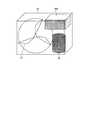
本実施の形態では、実施の形態1および2で説明したインバータ装置を空気調和機に適用する例について説明する。図4は、実施の形態3にかかる空気調和機の室外ユニットの構成概略図である。
In this embodiment, an example in which the inverter device described in Embodiments 1 and 2 is applied to an air conditioner will be described. FIG. 4 is a schematic configuration diagram of an outdoor unit of the air conditioner according to the third embodiment.
図4に示すように、実施の形態3にかかる空気調和機の室外ユニット30は、室外熱交換器(図示せず)と外気との熱交換を促進するためのファン31、空気調和機内の冷媒回路(図示せず)に圧縮した冷媒を循環させる圧縮機32、および実施の形態1または2にかかるインバータ装置100を備えている。 As shown in FIG. 4, the
図4に示す例では、インバータ装置100は、室外ユニット30内の上部に設置され、圧縮機32内に備えられた圧縮機モータの回転動作を制御する。なお、インバータ装置100は、圧縮機32内に備えられた圧縮機モータの回転動作の制御に使用されることに限定されるものではなく、例えば、ファン31や室内ユニット(図示せず)における送風用ファン(図示せず)を駆動するモータの回転動作を制御するものとしてもよい。 In the example shown in FIG. 4, the
以上説明したように、実施の形態3の空気調和機によれば、実施の形態1で説明したインバータ装置を適用することにより、第1のスイッチング素子と、第1のスイッチング素子よりもオン抵抗が小さく、且つ、スイッチング速度が速い第2のスイッチング素子とを並列に接続してスイッチング回路を構成し、第1のスイッチング素子よりも第2のスイッチング素子を遅れてオン動作させ、第2のスイッチング素子よりも第1のスイッチング素子を遅れてオフ動作させるようにしているので、第2のスイッチング素子をより高価なWBG半導体により構成した場合でも、電流容量が小さいデバイスを用いることができ、WBG半導体により構成されたスイッチング素子のみを用いたインバータ装置を用いた場合よりもコストを低減することができる。 As described above, according to the air conditioner of the third embodiment, by applying the inverter device described in the first embodiment, the on-resistance is higher than that of the first switching element and the first switching element. A second switching element having a small switching speed and a high switching speed is connected in parallel to form a switching circuit, and the second switching element is turned on later than the first switching element. Since the first switching element is turned off later than the second switching element, even when the second switching element is configured by a more expensive WBG semiconductor, a device having a small current capacity can be used. Costs can be reduced compared to the case of using an inverter device using only configured switching elements. Kill.
また、第1のスイッチング素子および第2のスイッチング素子が並列に接続された各スイッチング回路を1つの駆動信号により駆動するようにしているので、安価な汎用デバイスを用いて制御部あるいは駆動部を構成することができ、2つのスイッチング素子を並列に接続した同様の構成のインバータ装置を用いた場合よりもコストを低減することができる。 Further, since each switching circuit in which the first switching element and the second switching element are connected in parallel is driven by one drive signal, the control unit or the drive unit is configured using an inexpensive general-purpose device. The cost can be reduced as compared with the case of using an inverter device having a similar configuration in which two switching elements are connected in parallel.
また、Si系半導体により構成された第1のスイッチング素子によりオンオフ動作するため、スイッチング損失は、Si系半導体により構成されたスイッチング素子のみを用いて変換回路を構成したインバータ装置を用いた場合と同等となるものの、WBG半導体により構成された第2のスイッチング素子がオンしている期間は、スイッチング回路を流れる電流の大半が第2のスイッチング素子に流れるため、導通損失は、Si系半導体により構成されたスイッチング素子のみを用いて変換回路を構成したインバータ装置を用いた場合よりも小さくすることができる。 In addition, since the on / off operation is performed by the first switching element configured by the Si-based semiconductor, the switching loss is equivalent to that in the case of using the inverter device in which the conversion circuit is configured using only the switching element configured by the Si-based semiconductor. However, since most of the current flowing through the switching circuit flows to the second switching element during the period when the second switching element configured by the WBG semiconductor is on, the conduction loss is configured by the Si-based semiconductor. This can be made smaller than the case where an inverter device in which a conversion circuit is configured using only the switching elements is used.
また、実施の形態2で説明したインバータ装置を適用することにより、変換回路に接続された負荷が通常時とは異なる低負荷状態である場合に、第1のスイッチング素子のオンオフ動作を停止させ、第1のスイッチング素子よりもオン抵抗が小さく、且つ、スイッチング速度が速い第2のスイッチング素子のみをオンオフ動作させるようにしているので、2つのスイッチング素子を並列に接続した同様の構成のインバータ装置を用いた場合よりも低負荷状態における損失をより小さくすることができる。 Further, by applying the inverter device described in the second embodiment, when the load connected to the conversion circuit is in a low load state different from the normal time, the on / off operation of the first switching element is stopped, Since only the second switching element whose on-resistance is smaller than that of the first switching element and whose switching speed is fast is turned on / off, an inverter device having a similar configuration in which two switching elements are connected in parallel is provided. Loss in a low load state can be made smaller than when used.
また、例えば、圧縮機モータの回転動作に実施の形態2で説明したインバータ装置を適用した場合、PWM制御におけるキャリア周波数を通常時よりも高く設定することができるので、圧縮機モータの拘束通電を実施する際に、PWM信号のキャリア周波数を通常運転時よりも高く(例えば、20kHz以上)設定することにより、拘束通電中にモータから発生する騒音を可聴帯域外とすることができる。また、キャリア周波数を高く設定することにより、モータ巻線に発生する磁束を強くすることができるので、モータ巻線を加熱するだけでなく、モータ巻線に発生する磁束により、モータのコアをも加熱することができ、効率良く停止中の圧縮機モータ内の冷媒寝込みを防止することができる。 Further, for example, when the inverter device described in the second embodiment is applied to the rotation operation of the compressor motor, the carrier frequency in the PWM control can be set higher than normal, so that the compressor motor is restrained energized. At the time of implementation, by setting the carrier frequency of the PWM signal higher than that during normal operation (for example, 20 kHz or more), noise generated from the motor during restraint energization can be outside the audible band. Also, by setting the carrier frequency high, the magnetic flux generated in the motor winding can be strengthened, so that not only the motor winding is heated, but also the motor core is held by the magnetic flux generated in the motor winding. It is possible to heat and efficiently prevent the refrigerant stagnation in the compressor motor being stopped.
なお、上述した実施の形態において説明したWBG半導体により構成されたスイッチング素子を用いることによる効果は、各実施の形態において記載した効果にとどまらない。 Note that the effect obtained by using the switching element formed of the WBG semiconductor described in the above embodiment is not limited to the effect described in each embodiment.
例えば、WBG半導体によって構成されたスイッチング素子は、耐電圧性が高く、許容電流密度も高いため、スイッチング素子の小型化が可能であり、これら小型化されたスイッチング素子を用いることにより、これらの素子を組み込んだインバータ回路の小型化が可能となる。 For example, a switching element made of a WBG semiconductor has a high voltage resistance and a high allowable current density, so that the switching element can be downsized. By using these downsized switching elements, these elements can be used. It is possible to reduce the size of the inverter circuit incorporating the.
また、WBG半導体によって構成されたスイッチング素子は、耐熱性も高いため、ヒートシンクの放熱フィンの小型化が可能であるので、インバータ回路の一層の小型化が可能となる。 In addition, since the switching element formed of the WBG semiconductor has high heat resistance, the heat dissipating fins of the heat sink can be downsized, so that the inverter circuit can be further downsized.
なお、以上の実施の形態に示した構成は、本発明の構成の一例であり、別の公知の技術と組み合わせることも可能であるし、本発明の要旨を逸脱しない範囲で、一部を省略する等、変更して構成することも可能であることは言うまでもない。 Note that the configuration shown in the above embodiment is an example of the configuration of the present invention, and can be combined with another known technique, and a part thereof is omitted without departing from the gist of the present invention. Needless to say, it is possible to change the configuration.
1 交流電源
2 リアクトル
3 ダイオードブリッジ(整流回路)
4 変換回路
5 スイッチング回路
6,6a,6b 平滑コンデンサ
7 スイッチ
8 第1のスイッチング素子
9 第2のスイッチング素子
10 還流ダイオード
11 抵抗
12 三相モータ(負荷)
13 電流検出部
14 電圧検出部
15 PWM信号生成部
16 駆動部
17,17a ゲート回路
18 トランジスタ
30 室外ユニット
31 ファン
32 圧縮機
51,52,53,54 抵抗
61,62,63,64 ダイオード
100 インバータ装置
200,200a 制御部1 AC power supply 2
4
DESCRIPTION OF
Claims (7)
Translated fromJapanese前記変換回路は、
第1のスイッチング素子と、
前記第1のスイッチング素子と並列に接続され、前記第1のスイッチング素子よりも導通損失が小さく、且つ、スイッチング速度が速い第2のスイッチング素子と、
を備える複数のスイッチング回路により構成され、
前記制御部は、
前記各スイッチング回路をそれぞれオンオフ駆動するための複数の駆動信号を生成する駆動部と、
前記各スイッチング回路毎に、前記各駆動信号に基づき前記第1のスイッチング素子をオン動作させるタイミングよりも当該第1のスイッチング素子に並列接続された前記第2のスイッチング素子を遅れてオン動作させ、前記第2のスイッチング素子をオフ動作させるタイミングよりも当該第2のスイッチング素子に並列接続された前記第1のスイッチング素子を遅れてオフ動作させるゲート回路と、
を備える
ことを特徴とするインバータ装置。A rectifier circuit that rectifies an AC voltage output from an AC power source into a DC voltage, a smoothing capacitor that smoothes the DC voltage rectified by the rectifier circuit, and a converter that converts the DC voltage smoothed by the smoothing capacitor into a desired AC voltage In an inverter device including a circuit and a control unit that controls the conversion circuit,
The conversion circuit includes:
A first switching element;
A second switching element connected in parallel with the first switching element, having a conduction loss smaller than that of the first switching element and having a high switching speed;
Comprising a plurality of switching circuits comprising
The controller is
A drive unit for generating a plurality of drive signals for driving each of the switching circuits on and off;
For each of the switching circuits,to turn on the second switching elementconnected in parallel to the first switching element with respectto the timing of turning on the first switching element based on the drive signal, A gate circuit that turns off the first switching elementconnected in parallel to the second switching element after thetiming of turning offthe second switching element ;
An inverter device comprising:
前記駆動部から前記第1のスイッチング素子の制御端子に電流が流れる向きに直列接続された第1のダイオードおよび第1の抵抗と、
前記第1のスイッチング素子の制御端子から前記駆動部に電流が流れる向きに直列接続された第2のダイオードおよび第2の抵抗と、
前記駆動部から前記第2のスイッチング素子の制御端子に電流が流れる向きに直列接続された第3のダイオードおよび第3の抵抗と、
前記第2のスイッチング素子の制御端子から前記駆動部に電流が流れる向きに直列接続された第4のダイオードおよび第4の抵抗と、
を前記各スイッチング回路に対してそれぞれ備え、
前記第1の抵抗の抵抗値は、前記第3の抵抗の抵抗値よりも小さく、前記第2の抵抗の抵抗値は、前記第4の抵抗の抵抗値よりも大きいことを特徴とする請求項1に記載のインバータ装置。The gate circuit is
A first diode and a first resistor connected in series in a direction in which a current flows from the driving unit to a control terminal of the first switching element;
A second diode and a second resistor connected in series in a direction in which a current flows from the control terminal of the first switching element to the driving unit;
A third diode and a third resistor connected in series in a direction in which a current flows from the driving unit to the control terminal of the second switching element;
A fourth diode and a fourth resistor connected in series in a direction in which a current flows from the control terminal of the second switching element to the driving unit;
For each of the switching circuits,
The resistance value of the first resistor is smaller than the resistance value of the third resistor, and the resistance value of the second resistor is larger than the resistance value of the fourth resistor. The inverter device according to 1.
前記制御部は、前記変換回路の負荷が通常時とは異なる低負荷状態または拘束通電時の場合に、前記トランジスタをオンに制御する
ことを特徴とする請求項2に記載のインバータ装置。The gate circuit further includes, for each switching circuit, a plurality of transistors that short-circuit the control terminal and the output terminal of the first switching element,
3. The inverter device according to claim 2, wherein the control unit controls the transistor to be turned on when a load of the conversion circuit is in a low load state different from a normal time or in a restricted energization state.
冷却または加温された空気を室内に送り出す送風用ファンを有する室内ユニットと、
冷媒を圧縮する圧縮機、前記冷媒と外気との熱交換を実施する熱交換器、および該熱交換器に外気を送り込むファンを有する室外ユニットと、
を備え、
前記送風用ファン、前記圧縮機、あるいは前記ファンを駆動するモータのうちの1つあるいは複数がそれぞれに対応する前記インバータ装置により回転駆動されることを特徴とする空気調和機。One or more inverter devices according to any one of claims 1to 6;
An indoor unit having a blower fan for sending out cooled or heated air into the room;
An outdoor unit having a compressor that compresses the refrigerant, a heat exchanger that performs heat exchange between the refrigerant and outside air, and a fan that sends outside air to the heat exchanger;
With
One or more of the fan for blowing, the compressor, or the motor for driving the fan are rotationally driven by the corresponding inverter device, respectively.
Priority Applications (6)
| Application Number | Priority Date | Filing Date | Title |
|---|---|---|---|
| JP2011257386AJP5591213B2 (en) | 2011-11-25 | 2011-11-25 | Inverter device and air conditioner equipped with the same |
| US13/604,892US8884560B2 (en) | 2011-11-25 | 2012-09-06 | Inverter device and air conditioner including the same |
| ES12190706.7TES2689796T3 (en) | 2011-11-25 | 2012-10-31 | Inverter device and air conditioner that includes the same |
| EP12190706.7AEP2597767B1 (en) | 2011-11-25 | 2012-10-31 | Inverter device and air conditioner including the same |
| AU2012254876AAU2012254876B2 (en) | 2011-11-25 | 2012-11-14 | Inverter device and air conditioner including the same |
| CN201210475309.7ACN103138596B (en) | 2011-11-25 | 2012-11-21 | DC-to-AC converter and possess the air regulator of DC-to-AC converter |
Applications Claiming Priority (1)
| Application Number | Priority Date | Filing Date | Title |
|---|---|---|---|
| JP2011257386AJP5591213B2 (en) | 2011-11-25 | 2011-11-25 | Inverter device and air conditioner equipped with the same |
Publications (3)
| Publication Number | Publication Date |
|---|---|
| JP2013115855A JP2013115855A (en) | 2013-06-10 |
| JP2013115855A5 JP2013115855A5 (en) | 2013-08-15 |
| JP5591213B2true JP5591213B2 (en) | 2014-09-17 |
Family
ID=47290617
Family Applications (1)
| Application Number | Title | Priority Date | Filing Date |
|---|---|---|---|
| JP2011257386AExpired - Fee RelatedJP5591213B2 (en) | 2011-11-25 | 2011-11-25 | Inverter device and air conditioner equipped with the same |
Country Status (6)
| Country | Link |
|---|---|
| US (1) | US8884560B2 (en) |
| EP (1) | EP2597767B1 (en) |
| JP (1) | JP5591213B2 (en) |
| CN (1) | CN103138596B (en) |
| AU (1) | AU2012254876B2 (en) |
| ES (1) | ES2689796T3 (en) |
Cited By (1)
| Publication number | Priority date | Publication date | Assignee | Title |
|---|---|---|---|---|
| KR20150006779A (en)* | 2013-07-09 | 2015-01-19 | 세미크론 엘렉트로니크 지엠비에치 앤드 코. 케이지 | Power semiconductor circuit |
Families Citing this family (322)
| Publication number | Priority date | Publication date | Assignee | Title |
|---|---|---|---|---|
| US20070084897A1 (en) | 2003-05-20 | 2007-04-19 | Shelton Frederick E Iv | Articulating surgical stapling instrument incorporating a two-piece e-beam firing mechanism |
| US9060770B2 (en) | 2003-05-20 | 2015-06-23 | Ethicon Endo-Surgery, Inc. | Robotically-driven surgical instrument with E-beam driver |
| US11890012B2 (en) | 2004-07-28 | 2024-02-06 | Cilag Gmbh International | Staple cartridge comprising cartridge body and attached support |
| US9072535B2 (en) | 2011-05-27 | 2015-07-07 | Ethicon Endo-Surgery, Inc. | Surgical stapling instruments with rotatable staple deployment arrangements |
| US7669746B2 (en) | 2005-08-31 | 2010-03-02 | Ethicon Endo-Surgery, Inc. | Staple cartridges for forming staples having differing formed staple heights |
| US7934630B2 (en) | 2005-08-31 | 2011-05-03 | Ethicon Endo-Surgery, Inc. | Staple cartridges for forming staples having differing formed staple heights |
| US11484312B2 (en) | 2005-08-31 | 2022-11-01 | Cilag Gmbh International | Staple cartridge comprising a staple driver arrangement |
| US11246590B2 (en) | 2005-08-31 | 2022-02-15 | Cilag Gmbh International | Staple cartridge including staple drivers having different unfired heights |
| US10159482B2 (en) | 2005-08-31 | 2018-12-25 | Ethicon Llc | Fastener cartridge assembly comprising a fixed anvil and different staple heights |
| US20070106317A1 (en) | 2005-11-09 | 2007-05-10 | Shelton Frederick E Iv | Hydraulically and electrically actuated articulation joints for surgical instruments |
| US20110295295A1 (en) | 2006-01-31 | 2011-12-01 | Ethicon Endo-Surgery, Inc. | Robotically-controlled surgical instrument having recording capabilities |
| US8186555B2 (en) | 2006-01-31 | 2012-05-29 | Ethicon Endo-Surgery, Inc. | Motor-driven surgical cutting and fastening instrument with mechanical closure system |
| US8708213B2 (en) | 2006-01-31 | 2014-04-29 | Ethicon Endo-Surgery, Inc. | Surgical instrument having a feedback system |
| US20120292367A1 (en) | 2006-01-31 | 2012-11-22 | Ethicon Endo-Surgery, Inc. | Robotically-controlled end effector |
| US11278279B2 (en) | 2006-01-31 | 2022-03-22 | Cilag Gmbh International | Surgical instrument assembly |
| US11793518B2 (en) | 2006-01-31 | 2023-10-24 | Cilag Gmbh International | Powered surgical instruments with firing system lockout arrangements |
| US7845537B2 (en) | 2006-01-31 | 2010-12-07 | Ethicon Endo-Surgery, Inc. | Surgical instrument having recording capabilities |
| US7753904B2 (en) | 2006-01-31 | 2010-07-13 | Ethicon Endo-Surgery, Inc. | Endoscopic surgical instrument with a handle that can articulate with respect to the shaft |
| US8820603B2 (en) | 2006-01-31 | 2014-09-02 | Ethicon Endo-Surgery, Inc. | Accessing data stored in a memory of a surgical instrument |
| US8992422B2 (en) | 2006-03-23 | 2015-03-31 | Ethicon Endo-Surgery, Inc. | Robotically-controlled endoscopic accessory channel |
| US10568652B2 (en) | 2006-09-29 | 2020-02-25 | Ethicon Llc | Surgical staples having attached drivers of different heights and stapling instruments for deploying the same |
| US11980366B2 (en) | 2006-10-03 | 2024-05-14 | Cilag Gmbh International | Surgical instrument |
| US11291441B2 (en) | 2007-01-10 | 2022-04-05 | Cilag Gmbh International | Surgical instrument with wireless communication between control unit and remote sensor |
| US8684253B2 (en) | 2007-01-10 | 2014-04-01 | Ethicon Endo-Surgery, Inc. | Surgical instrument with wireless communication between a control unit of a robotic system and remote sensor |
| US8632535B2 (en) | 2007-01-10 | 2014-01-21 | Ethicon Endo-Surgery, Inc. | Interlock and surgical instrument including same |
| US20080169333A1 (en) | 2007-01-11 | 2008-07-17 | Shelton Frederick E | Surgical stapler end effector with tapered distal end |
| US7673782B2 (en) | 2007-03-15 | 2010-03-09 | Ethicon Endo-Surgery, Inc. | Surgical stapling instrument having a releasable buttress material |
| US8931682B2 (en) | 2007-06-04 | 2015-01-13 | Ethicon Endo-Surgery, Inc. | Robotically-controlled shaft based rotary drive systems for surgical instruments |
| US11564682B2 (en) | 2007-06-04 | 2023-01-31 | Cilag Gmbh International | Surgical stapler device |
| US7753245B2 (en) | 2007-06-22 | 2010-07-13 | Ethicon Endo-Surgery, Inc. | Surgical stapling instruments |
| US11849941B2 (en) | 2007-06-29 | 2023-12-26 | Cilag Gmbh International | Staple cartridge having staple cavities extending at a transverse angle relative to a longitudinal cartridge axis |
| US7819298B2 (en) | 2008-02-14 | 2010-10-26 | Ethicon Endo-Surgery, Inc. | Surgical stapling apparatus with control features operable with one hand |
| US8573465B2 (en) | 2008-02-14 | 2013-11-05 | Ethicon Endo-Surgery, Inc. | Robotically-controlled surgical end effector system with rotary actuated closure systems |
| US11986183B2 (en) | 2008-02-14 | 2024-05-21 | Cilag Gmbh International | Surgical cutting and fastening instrument comprising a plurality of sensors to measure an electrical parameter |
| US8636736B2 (en) | 2008-02-14 | 2014-01-28 | Ethicon Endo-Surgery, Inc. | Motorized surgical cutting and fastening instrument |
| US7866527B2 (en) | 2008-02-14 | 2011-01-11 | Ethicon Endo-Surgery, Inc. | Surgical stapling apparatus with interlockable firing system |
| JP5410110B2 (en) | 2008-02-14 | 2014-02-05 | エシコン・エンド−サージェリィ・インコーポレイテッド | Surgical cutting / fixing instrument with RF electrode |
| US9179912B2 (en) | 2008-02-14 | 2015-11-10 | Ethicon Endo-Surgery, Inc. | Robotically-controlled motorized surgical cutting and fastening instrument |
| US9585657B2 (en) | 2008-02-15 | 2017-03-07 | Ethicon Endo-Surgery, Llc | Actuator for releasing a layer of material from a surgical end effector |
| US8210411B2 (en) | 2008-09-23 | 2012-07-03 | Ethicon Endo-Surgery, Inc. | Motor-driven surgical cutting instrument |
| US9386983B2 (en) | 2008-09-23 | 2016-07-12 | Ethicon Endo-Surgery, Llc | Robotically-controlled motorized surgical instrument |
| US9005230B2 (en) | 2008-09-23 | 2015-04-14 | Ethicon Endo-Surgery, Inc. | Motorized surgical instrument |
| US11648005B2 (en) | 2008-09-23 | 2023-05-16 | Cilag Gmbh International | Robotically-controlled motorized surgical instrument with an end effector |
| US8608045B2 (en) | 2008-10-10 | 2013-12-17 | Ethicon Endo-Sugery, Inc. | Powered surgical cutting and stapling apparatus with manually retractable firing system |
| US8220688B2 (en) | 2009-12-24 | 2012-07-17 | Ethicon Endo-Surgery, Inc. | Motor-driven surgical cutting instrument with electric actuator directional control assembly |
| US11925354B2 (en) | 2010-09-30 | 2024-03-12 | Cilag Gmbh International | Staple cartridge comprising staples positioned within a compressible portion thereof |
| US9386988B2 (en) | 2010-09-30 | 2016-07-12 | Ethicon End-Surgery, LLC | Retainer assembly including a tissue thickness compensator |
| US10945731B2 (en) | 2010-09-30 | 2021-03-16 | Ethicon Llc | Tissue thickness compensator comprising controlled release and expansion |
| US11812965B2 (en) | 2010-09-30 | 2023-11-14 | Cilag Gmbh International | Layer of material for a surgical end effector |
| US9016542B2 (en) | 2010-09-30 | 2015-04-28 | Ethicon Endo-Surgery, Inc. | Staple cartridge comprising compressible distortion resistant components |
| US12213666B2 (en) | 2010-09-30 | 2025-02-04 | Cilag Gmbh International | Tissue thickness compensator comprising layers |
| US11298125B2 (en) | 2010-09-30 | 2022-04-12 | Cilag Gmbh International | Tissue stapler having a thickness compensator |
| US9351730B2 (en) | 2011-04-29 | 2016-05-31 | Ethicon Endo-Surgery, Llc | Tissue thickness compensator comprising channels |
| US9629814B2 (en) | 2010-09-30 | 2017-04-25 | Ethicon Endo-Surgery, Llc | Tissue thickness compensator configured to redistribute compressive forces |
| US9788834B2 (en) | 2010-09-30 | 2017-10-17 | Ethicon Llc | Layer comprising deployable attachment members |
| US8695866B2 (en) | 2010-10-01 | 2014-04-15 | Ethicon Endo-Surgery, Inc. | Surgical instrument having a power control circuit |
| AU2012250197B2 (en) | 2011-04-29 | 2017-08-10 | Ethicon Endo-Surgery, Inc. | Staple cartridge comprising staples positioned within a compressible portion thereof |
| US11207064B2 (en) | 2011-05-27 | 2021-12-28 | Cilag Gmbh International | Automated end effector component reloading system for use with a robotic system |
| MX358135B (en) | 2012-03-28 | 2018-08-06 | Ethicon Endo Surgery Inc | Tissue thickness compensator comprising a plurality of layers. |
| BR112014024098B1 (en) | 2012-03-28 | 2021-05-25 | Ethicon Endo-Surgery, Inc. | staple cartridge |
| US9101358B2 (en) | 2012-06-15 | 2015-08-11 | Ethicon Endo-Surgery, Inc. | Articulatable surgical instrument comprising a firing drive |
| US12383267B2 (en) | 2012-06-28 | 2025-08-12 | Cilag Gmbh International | Robotically powered surgical device with manually-actuatable reversing system |
| US9408606B2 (en) | 2012-06-28 | 2016-08-09 | Ethicon Endo-Surgery, Llc | Robotically powered surgical device with manually-actuatable reversing system |
| US9289256B2 (en) | 2012-06-28 | 2016-03-22 | Ethicon Endo-Surgery, Llc | Surgical end effectors having angled tissue-contacting surfaces |
| US9282974B2 (en) | 2012-06-28 | 2016-03-15 | Ethicon Endo-Surgery, Llc | Empty clip cartridge lockout |
| BR112014032776B1 (en) | 2012-06-28 | 2021-09-08 | Ethicon Endo-Surgery, Inc | SURGICAL INSTRUMENT SYSTEM AND SURGICAL KIT FOR USE WITH A SURGICAL INSTRUMENT SYSTEM |
| US20140001231A1 (en) | 2012-06-28 | 2014-01-02 | Ethicon Endo-Surgery, Inc. | Firing system lockout arrangements for surgical instruments |
| BR112015021082B1 (en) | 2013-03-01 | 2022-05-10 | Ethicon Endo-Surgery, Inc | surgical instrument |
| RU2672520C2 (en) | 2013-03-01 | 2018-11-15 | Этикон Эндо-Серджери, Инк. | Hingedly turnable surgical instruments with conducting ways for signal transfer |
| US9629629B2 (en) | 2013-03-14 | 2017-04-25 | Ethicon Endo-Surgey, LLC | Control systems for surgical instruments |
| BR112015026109B1 (en) | 2013-04-16 | 2022-02-22 | Ethicon Endo-Surgery, Inc | surgical instrument |
| US9826976B2 (en) | 2013-04-16 | 2017-11-28 | Ethicon Llc | Motor driven surgical instruments with lockable dual drive shafts |
| MX369362B (en) | 2013-08-23 | 2019-11-06 | Ethicon Endo Surgery Llc | Firing member retraction devices for powered surgical instruments. |
| US9775609B2 (en) | 2013-08-23 | 2017-10-03 | Ethicon Llc | Tamper proof circuit for surgical instrument battery pack |
| JP2015171226A (en)* | 2014-03-06 | 2015-09-28 | 三菱電機株式会社 | inverter device and air conditioner |
| US12232723B2 (en) | 2014-03-26 | 2025-02-25 | Cilag Gmbh International | Systems and methods for controlling a segmented circuit |
| BR112016021943B1 (en) | 2014-03-26 | 2022-06-14 | Ethicon Endo-Surgery, Llc | SURGICAL INSTRUMENT FOR USE BY AN OPERATOR IN A SURGICAL PROCEDURE |
| US10013049B2 (en) | 2014-03-26 | 2018-07-03 | Ethicon Llc | Power management through sleep options of segmented circuit and wake up control |
| US20150272580A1 (en) | 2014-03-26 | 2015-10-01 | Ethicon Endo-Surgery, Inc. | Verification of number of battery exchanges/procedure count |
| US10327764B2 (en) | 2014-09-26 | 2019-06-25 | Ethicon Llc | Method for creating a flexible staple line |
| BR112016023825B1 (en) | 2014-04-16 | 2022-08-02 | Ethicon Endo-Surgery, Llc | STAPLE CARTRIDGE FOR USE WITH A SURGICAL STAPLER AND STAPLE CARTRIDGE FOR USE WITH A SURGICAL INSTRUMENT |
| CN106456159B (en) | 2014-04-16 | 2019-03-08 | 伊西康内外科有限责任公司 | Fastener Cartridge Assembly and Nail Retainer Cover Arrangement |
| US20150297225A1 (en) | 2014-04-16 | 2015-10-22 | Ethicon Endo-Surgery, Inc. | Fastener cartridges including extensions having different configurations |
| CN106456176B (en) | 2014-04-16 | 2019-06-28 | 伊西康内外科有限责任公司 | Fastener Cartridge Including Extensions With Different Configurations |
| GB2528980A (en)* | 2014-08-08 | 2016-02-10 | Reinhausen Maschf Scheubeck | Voltage balancing in series connected power switches |
| CN104143924B (en)* | 2014-08-18 | 2016-08-24 | 浙江易控电子科技有限公司 | A kind of low cost converter |
| US10135242B2 (en) | 2014-09-05 | 2018-11-20 | Ethicon Llc | Smart cartridge wake up operation and data retention |
| BR112017004361B1 (en) | 2014-09-05 | 2023-04-11 | Ethicon Llc | ELECTRONIC SYSTEM FOR A SURGICAL INSTRUMENT |
| US11311294B2 (en) | 2014-09-05 | 2022-04-26 | Cilag Gmbh International | Powered medical device including measurement of closure state of jaws |
| US10105142B2 (en) | 2014-09-18 | 2018-10-23 | Ethicon Llc | Surgical stapler with plurality of cutting elements |
| US10690370B2 (en)* | 2014-09-26 | 2020-06-23 | Mitsubishi Electric Corporation | Indoor equipment and air conditioner |
| US11523821B2 (en) | 2014-09-26 | 2022-12-13 | Cilag Gmbh International | Method for creating a flexible staple line |
| US9924944B2 (en) | 2014-10-16 | 2018-03-27 | Ethicon Llc | Staple cartridge comprising an adjunct material |
| US10517594B2 (en) | 2014-10-29 | 2019-12-31 | Ethicon Llc | Cartridge assemblies for surgical staplers |
| US11141153B2 (en) | 2014-10-29 | 2021-10-12 | Cilag Gmbh International | Staple cartridges comprising driver arrangements |
| CN107076468A (en)* | 2014-11-04 | 2017-08-18 | 三菱电机株式会社 | Heat pump device, air conditioner having same, heat pump water heater and refrigerator |
| US9844376B2 (en) | 2014-11-06 | 2017-12-19 | Ethicon Llc | Staple cartridge comprising a releasable adjunct material |
| US10736636B2 (en) | 2014-12-10 | 2020-08-11 | Ethicon Llc | Articulatable surgical instrument system |
| US10085748B2 (en) | 2014-12-18 | 2018-10-02 | Ethicon Llc | Locking arrangements for detachable shaft assemblies with articulatable surgical end effectors |
| US9943309B2 (en) | 2014-12-18 | 2018-04-17 | Ethicon Llc | Surgical instruments with articulatable end effectors and movable firing beam support arrangements |
| US9844375B2 (en) | 2014-12-18 | 2017-12-19 | Ethicon Llc | Drive arrangements for articulatable surgical instruments |
| US9844374B2 (en) | 2014-12-18 | 2017-12-19 | Ethicon Llc | Surgical instrument systems comprising an articulatable end effector and means for adjusting the firing stroke of a firing member |
| US9987000B2 (en) | 2014-12-18 | 2018-06-05 | Ethicon Llc | Surgical instrument assembly comprising a flexible articulation system |
| MX389118B (en) | 2014-12-18 | 2025-03-20 | Ethicon Llc | SURGICAL INSTRUMENT WITH AN ANVIL THAT CAN BE SELECTIVELY MOVED ON A DISCRETE, NON-MOBILE AXIS RELATIVE TO A STAPLE CARTRIDGE. |
| WO2016103328A1 (en)* | 2014-12-22 | 2016-06-30 | 三菱電機株式会社 | Switching device, motor drive device, power conversion device, and switching method |
| JP2016158344A (en)* | 2015-02-24 | 2016-09-01 | 株式会社日立製作所 | Power conversion device and elevator |
| US11154301B2 (en) | 2015-02-27 | 2021-10-26 | Cilag Gmbh International | Modular stapling assembly |
| US9993248B2 (en) | 2015-03-06 | 2018-06-12 | Ethicon Endo-Surgery, Llc | Smart sensors with local signal processing |
| US10441279B2 (en) | 2015-03-06 | 2019-10-15 | Ethicon Llc | Multiple level thresholds to modify operation of powered surgical instruments |
| US10548504B2 (en) | 2015-03-06 | 2020-02-04 | Ethicon Llc | Overlaid multi sensor radio frequency (RF) electrode system to measure tissue compression |
| JP2020121162A (en) | 2015-03-06 | 2020-08-13 | エシコン エルエルシーEthicon LLC | Time dependent evaluation of sensor data to determine stability element, creep element and viscoelastic element of measurement |
| US10433844B2 (en) | 2015-03-31 | 2019-10-08 | Ethicon Llc | Surgical instrument with selectively disengageable threaded drive systems |
| US9484908B1 (en)* | 2015-06-19 | 2016-11-01 | Hella Corporate Center Usa, Inc. | Gate drive circuit |
| US10238386B2 (en) | 2015-09-23 | 2019-03-26 | Ethicon Llc | Surgical stapler having motor control based on an electrical parameter related to a motor current |
| US10105139B2 (en) | 2015-09-23 | 2018-10-23 | Ethicon Llc | Surgical stapler having downstream current-based motor control |
| US10299878B2 (en) | 2015-09-25 | 2019-05-28 | Ethicon Llc | Implantable adjunct systems for determining adjunct skew |
| US10433846B2 (en) | 2015-09-30 | 2019-10-08 | Ethicon Llc | Compressible adjunct with crossing spacer fibers |
| US11890015B2 (en) | 2015-09-30 | 2024-02-06 | Cilag Gmbh International | Compressible adjunct with crossing spacer fibers |
| US10478188B2 (en) | 2015-09-30 | 2019-11-19 | Ethicon Llc | Implantable layer comprising a constricted configuration |
| DE112016003958T5 (en)* | 2015-11-16 | 2018-05-30 | Aisin Aw Co., Ltd. | Power conversion device |
| JP6079861B1 (en)* | 2015-12-16 | 2017-02-15 | 株式会社明電舎 | Resonant load power converter and time-sharing operation method for resonant load power converter |
| US10265068B2 (en) | 2015-12-30 | 2019-04-23 | Ethicon Llc | Surgical instruments with separable motors and motor control circuits |
| US10292704B2 (en) | 2015-12-30 | 2019-05-21 | Ethicon Llc | Mechanisms for compensating for battery pack failure in powered surgical instruments |
| BR112018016098B1 (en) | 2016-02-09 | 2023-02-23 | Ethicon Llc | SURGICAL INSTRUMENT |
| US11213293B2 (en) | 2016-02-09 | 2022-01-04 | Cilag Gmbh International | Articulatable surgical instruments with single articulation link arrangements |
| US11224426B2 (en) | 2016-02-12 | 2022-01-18 | Cilag Gmbh International | Mechanisms for compensating for drivetrain failure in powered surgical instruments |
| US10448948B2 (en) | 2016-02-12 | 2019-10-22 | Ethicon Llc | Mechanisms for compensating for drivetrain failure in powered surgical instruments |
| US10320322B2 (en) | 2016-04-15 | 2019-06-11 | Emerson Climate Technologies, Inc. | Switch actuation measurement circuit for voltage converter |
| US10305373B2 (en) | 2016-04-15 | 2019-05-28 | Emerson Climate Technologies, Inc. | Input reference signal generation systems and methods |
| US10763740B2 (en) | 2016-04-15 | 2020-09-01 | Emerson Climate Technologies, Inc. | Switch off time control systems and methods |
| US10357247B2 (en) | 2016-04-15 | 2019-07-23 | Ethicon Llc | Surgical instrument with multiple program responses during a firing motion |
| US10656026B2 (en) | 2016-04-15 | 2020-05-19 | Emerson Climate Technologies, Inc. | Temperature sensing circuit for transmitting data across isolation barrier |
| US11387729B2 (en) | 2016-04-15 | 2022-07-12 | Emerson Climate Technologies, Inc. | Buck-converter-based drive circuits for driving motors of compressors and condenser fans |
| US9933842B2 (en) | 2016-04-15 | 2018-04-03 | Emerson Climate Technologies, Inc. | Microcontroller architecture for power factor correction converter |
| US10277115B2 (en) | 2016-04-15 | 2019-04-30 | Emerson Climate Technologies, Inc. | Filtering systems and methods for voltage control |
| US11607239B2 (en) | 2016-04-15 | 2023-03-21 | Cilag Gmbh International | Systems and methods for controlling a surgical stapling and cutting instrument |
| US10426467B2 (en) | 2016-04-15 | 2019-10-01 | Ethicon Llc | Surgical instrument with detection sensors |
| US10492783B2 (en) | 2016-04-15 | 2019-12-03 | Ethicon, Llc | Surgical instrument with improved stop/start control during a firing motion |
| US10828028B2 (en) | 2016-04-15 | 2020-11-10 | Ethicon Llc | Surgical instrument with multiple program responses during a firing motion |
| US10363037B2 (en) | 2016-04-18 | 2019-07-30 | Ethicon Llc | Surgical instrument system comprising a magnetic lockout |
| US20170296173A1 (en) | 2016-04-18 | 2017-10-19 | Ethicon Endo-Surgery, Llc | Method for operating a surgical instrument |
| US11317917B2 (en) | 2016-04-18 | 2022-05-03 | Cilag Gmbh International | Surgical stapling system comprising a lockable firing assembly |
| JP6621913B2 (en)* | 2016-04-27 | 2019-12-18 | 三菱電機株式会社 | Electric motor drive device, refrigeration cycle device, and air conditioner |
| US10500000B2 (en) | 2016-08-16 | 2019-12-10 | Ethicon Llc | Surgical tool with manual control of end effector jaws |
| US10542982B2 (en) | 2016-12-21 | 2020-01-28 | Ethicon Llc | Shaft assembly comprising first and second articulation lockouts |
| JP2020501815A (en) | 2016-12-21 | 2020-01-23 | エシコン エルエルシーEthicon LLC | Surgical stapling system |
| US20180168625A1 (en) | 2016-12-21 | 2018-06-21 | Ethicon Endo-Surgery, Llc | Surgical stapling instruments with smart staple cartridges |
| US20180168615A1 (en) | 2016-12-21 | 2018-06-21 | Ethicon Endo-Surgery, Llc | Method of deforming staples from two different types of staple cartridges with the same surgical stapling instrument |
| JP7010957B2 (en) | 2016-12-21 | 2022-01-26 | エシコン エルエルシー | Shaft assembly with lockout |
| US11419606B2 (en) | 2016-12-21 | 2022-08-23 | Cilag Gmbh International | Shaft assembly comprising a clutch configured to adapt the output of a rotary firing member to two different systems |
| US10582928B2 (en) | 2016-12-21 | 2020-03-10 | Ethicon Llc | Articulation lock arrangements for locking an end effector in an articulated position in response to actuation of a jaw closure system |
| US10973516B2 (en) | 2016-12-21 | 2021-04-13 | Ethicon Llc | Surgical end effectors and adaptable firing members therefor |
| JP7010956B2 (en) | 2016-12-21 | 2022-01-26 | エシコン エルエルシー | How to staple tissue |
| JP6983893B2 (en) | 2016-12-21 | 2021-12-17 | エシコン エルエルシーEthicon LLC | Lockout configuration for surgical end effectors and replaceable tool assemblies |
| US10813638B2 (en) | 2016-12-21 | 2020-10-27 | Ethicon Llc | Surgical end effectors with expandable tissue stop arrangements |
| MX2019007295A (en) | 2016-12-21 | 2019-10-15 | Ethicon Llc | Surgical instrument system comprising an end effector lockout and a firing assembly lockout. |
| US11090048B2 (en) | 2016-12-21 | 2021-08-17 | Cilag Gmbh International | Method for resetting a fuse of a surgical instrument shaft |
| JP2018107494A (en)* | 2016-12-22 | 2018-07-05 | ルネサスエレクトロニクス株式会社 | Semiconductor device and inverter system |
| CN107143966B (en)* | 2017-03-21 | 2019-12-10 | 深圳达实智能股份有限公司 | Control method and device for magnetic suspension cold water main machine of hospital central air-conditioning system |
| CN106969465B (en)* | 2017-03-21 | 2019-09-20 | 深圳达实智能股份有限公司 | Central air-conditioning in office building system magnetic suspension cold water host control method and device |
| US10307170B2 (en) | 2017-06-20 | 2019-06-04 | Ethicon Llc | Method for closed loop control of motor velocity of a surgical stapling and cutting instrument |
| US10881399B2 (en) | 2017-06-20 | 2021-01-05 | Ethicon Llc | Techniques for adaptive control of motor velocity of a surgical stapling and cutting instrument |
| US11653914B2 (en) | 2017-06-20 | 2023-05-23 | Cilag Gmbh International | Systems and methods for controlling motor velocity of a surgical stapling and cutting instrument according to articulation angle of end effector |
| US11517325B2 (en) | 2017-06-20 | 2022-12-06 | Cilag Gmbh International | Closed loop feedback control of motor velocity of a surgical stapling and cutting instrument based on measured displacement distance traveled over a specified time interval |
| US11382638B2 (en) | 2017-06-20 | 2022-07-12 | Cilag Gmbh International | Closed loop feedback control of motor velocity of a surgical stapling and cutting instrument based on measured time over a specified displacement distance |
| US10779820B2 (en) | 2017-06-20 | 2020-09-22 | Ethicon Llc | Systems and methods for controlling motor speed according to user input for a surgical instrument |
| US11324503B2 (en) | 2017-06-27 | 2022-05-10 | Cilag Gmbh International | Surgical firing member arrangements |
| US10993716B2 (en) | 2017-06-27 | 2021-05-04 | Ethicon Llc | Surgical anvil arrangements |
| US11266405B2 (en) | 2017-06-27 | 2022-03-08 | Cilag Gmbh International | Surgical anvil manufacturing methods |
| US10765427B2 (en) | 2017-06-28 | 2020-09-08 | Ethicon Llc | Method for articulating a surgical instrument |
| EP3420947B1 (en) | 2017-06-28 | 2022-05-25 | Cilag GmbH International | Surgical instrument comprising selectively actuatable rotatable couplers |
| US10758232B2 (en) | 2017-06-28 | 2020-09-01 | Ethicon Llc | Surgical instrument with positive jaw opening features |
| US11564686B2 (en) | 2017-06-28 | 2023-01-31 | Cilag Gmbh International | Surgical shaft assemblies with flexible interfaces |
| USD906355S1 (en) | 2017-06-28 | 2020-12-29 | Ethicon Llc | Display screen or portion thereof with a graphical user interface for a surgical instrument |
| US11484310B2 (en) | 2017-06-28 | 2022-11-01 | Cilag Gmbh International | Surgical instrument comprising a shaft including a closure tube profile |
| US10932772B2 (en) | 2017-06-29 | 2021-03-02 | Ethicon Llc | Methods for closed loop velocity control for robotic surgical instrument |
| US11257811B2 (en) | 2017-07-14 | 2022-02-22 | Cambridge Enterprise Limited | Power semiconductor device with an auxiliary gate structure |
| GB2564482B (en) | 2017-07-14 | 2021-02-10 | Cambridge Entpr Ltd | A power semiconductor device with a double gate structure |
| US11336279B2 (en) | 2017-07-14 | 2022-05-17 | Cambridge Enterprise Limited | Power semiconductor device with a series connection of two devices |
| US11944300B2 (en) | 2017-08-03 | 2024-04-02 | Cilag Gmbh International | Method for operating a surgical system bailout |
| US11304695B2 (en) | 2017-08-03 | 2022-04-19 | Cilag Gmbh International | Surgical system shaft interconnection |
| US11974742B2 (en) | 2017-08-03 | 2024-05-07 | Cilag Gmbh International | Surgical system comprising an articulation bailout |
| US11471155B2 (en) | 2017-08-03 | 2022-10-18 | Cilag Gmbh International | Surgical system bailout |
| US10743872B2 (en) | 2017-09-29 | 2020-08-18 | Ethicon Llc | System and methods for controlling a display of a surgical instrument |
| US11134944B2 (en) | 2017-10-30 | 2021-10-05 | Cilag Gmbh International | Surgical stapler knife motion controls |
| US10842490B2 (en) | 2017-10-31 | 2020-11-24 | Ethicon Llc | Cartridge body design with force reduction based on firing completion |
| US10779826B2 (en) | 2017-12-15 | 2020-09-22 | Ethicon Llc | Methods of operating surgical end effectors |
| US10835330B2 (en) | 2017-12-19 | 2020-11-17 | Ethicon Llc | Method for determining the position of a rotatable jaw of a surgical instrument attachment assembly |
| US11179151B2 (en) | 2017-12-21 | 2021-11-23 | Cilag Gmbh International | Surgical instrument comprising a display |
| US11311290B2 (en) | 2017-12-21 | 2022-04-26 | Cilag Gmbh International | Surgical instrument comprising an end effector dampener |
| US12336705B2 (en) | 2017-12-21 | 2025-06-24 | Cilag Gmbh International | Continuous use self-propelled stapling instrument |
| CN108696187B (en)* | 2018-04-24 | 2019-07-02 | 南京信息职业技术学院 | Construction method of suspension system for observing parameters of bearingless synchronous reluctance motor |
| CN110594987A (en)* | 2018-06-13 | 2019-12-20 | 广东美的制冷设备有限公司 | Air conditioner and integrated air conditioner controller |
| WO2020031111A1 (en)* | 2018-08-08 | 2020-02-13 | HELLA GmbH & Co. KGaA | Performance enhancement of silicon-based device |
| US11324501B2 (en) | 2018-08-20 | 2022-05-10 | Cilag Gmbh International | Surgical stapling devices with improved closure members |
| US20200054321A1 (en) | 2018-08-20 | 2020-02-20 | Ethicon Llc | Surgical instruments with progressive jaw closure arrangements |
| US11291440B2 (en) | 2018-08-20 | 2022-04-05 | Cilag Gmbh International | Method for operating a powered articulatable surgical instrument |
| US11207065B2 (en) | 2018-08-20 | 2021-12-28 | Cilag Gmbh International | Method for fabricating surgical stapler anvils |
| CN109525127B (en)* | 2018-12-29 | 2020-05-05 | 广东美的制冷设备有限公司 | Power device and electric appliance |
| JP7183797B2 (en)* | 2019-01-08 | 2022-12-06 | 株式会社デンソー | power converter |
| US11696761B2 (en) | 2019-03-25 | 2023-07-11 | Cilag Gmbh International | Firing drive arrangements for surgical systems |
| JP2020167612A (en)* | 2019-03-29 | 2020-10-08 | 住友電装株式会社 | Power supply control device |
| US11471157B2 (en) | 2019-04-30 | 2022-10-18 | Cilag Gmbh International | Articulation control mapping for a surgical instrument |
| US11648009B2 (en) | 2019-04-30 | 2023-05-16 | Cilag Gmbh International | Rotatable jaw tip for a surgical instrument |
| US11253254B2 (en) | 2019-04-30 | 2022-02-22 | Cilag Gmbh International | Shaft rotation actuator on a surgical instrument |
| US11432816B2 (en) | 2019-04-30 | 2022-09-06 | Cilag Gmbh International | Articulation pin for a surgical instrument |
| US11452528B2 (en) | 2019-04-30 | 2022-09-27 | Cilag Gmbh International | Articulation actuators for a surgical instrument |
| US11426251B2 (en) | 2019-04-30 | 2022-08-30 | Cilag Gmbh International | Articulation directional lights on a surgical instrument |
| US11903581B2 (en) | 2019-04-30 | 2024-02-20 | Cilag Gmbh International | Methods for stapling tissue using a surgical instrument |
| US12382651B2 (en) | 2019-05-07 | 2025-08-05 | Cambridge Gan Devices Limited | Power semiconductor device with an auxiliary gate structure |
| US11955478B2 (en)* | 2019-05-07 | 2024-04-09 | Cambridge Gan Devices Limited | Power semiconductor device with an auxiliary gate structure |
| JP7205402B2 (en)* | 2019-06-25 | 2023-01-17 | 株式会社デンソー | parallel switching circuit |
| US11684434B2 (en) | 2019-06-28 | 2023-06-27 | Cilag Gmbh International | Surgical RFID assemblies for instrument operational setting control |
| US11241235B2 (en) | 2019-06-28 | 2022-02-08 | Cilag Gmbh International | Method of using multiple RFID chips with a surgical assembly |
| US11376098B2 (en) | 2019-06-28 | 2022-07-05 | Cilag Gmbh International | Surgical instrument system comprising an RFID system |
| US11291451B2 (en) | 2019-06-28 | 2022-04-05 | Cilag Gmbh International | Surgical instrument with battery compatibility verification functionality |
| US11464601B2 (en) | 2019-06-28 | 2022-10-11 | Cilag Gmbh International | Surgical instrument comprising an RFID system for tracking a movable component |
| US11627959B2 (en) | 2019-06-28 | 2023-04-18 | Cilag Gmbh International | Surgical instruments including manual and powered system lockouts |
| US11638587B2 (en) | 2019-06-28 | 2023-05-02 | Cilag Gmbh International | RFID identification systems for surgical instruments |
| US11478241B2 (en) | 2019-06-28 | 2022-10-25 | Cilag Gmbh International | Staple cartridge including projections |
| US11660163B2 (en) | 2019-06-28 | 2023-05-30 | Cilag Gmbh International | Surgical system with RFID tags for updating motor assembly parameters |
| US11298132B2 (en) | 2019-06-28 | 2022-04-12 | Cilag GmbH Inlernational | Staple cartridge including a honeycomb extension |
| US11426167B2 (en) | 2019-06-28 | 2022-08-30 | Cilag Gmbh International | Mechanisms for proper anvil attachment surgical stapling head assembly |
| US11771419B2 (en) | 2019-06-28 | 2023-10-03 | Cilag Gmbh International | Packaging for a replaceable component of a surgical stapling system |
| US11497492B2 (en) | 2019-06-28 | 2022-11-15 | Cilag Gmbh International | Surgical instrument including an articulation lock |
| US11553971B2 (en) | 2019-06-28 | 2023-01-17 | Cilag Gmbh International | Surgical RFID assemblies for display and communication |
| US11853835B2 (en) | 2019-06-28 | 2023-12-26 | Cilag Gmbh International | RFID identification systems for surgical instruments |
| US11399837B2 (en) | 2019-06-28 | 2022-08-02 | Cilag Gmbh International | Mechanisms for motor control adjustments of a motorized surgical instrument |
| US11523822B2 (en) | 2019-06-28 | 2022-12-13 | Cilag Gmbh International | Battery pack including a circuit interrupter |
| US11361176B2 (en) | 2019-06-28 | 2022-06-14 | Cilag Gmbh International | Surgical RFID assemblies for compatibility detection |
| US11298127B2 (en) | 2019-06-28 | 2022-04-12 | Cilag GmbH Interational | Surgical stapling system having a lockout mechanism for an incompatible cartridge |
| US12004740B2 (en) | 2019-06-28 | 2024-06-11 | Cilag Gmbh International | Surgical stapling system having an information decryption protocol |
| EP4029139A4 (en) | 2019-09-13 | 2023-09-27 | Milwaukee Electric Tool Corporation | WIDE BAND GAP SEMICONDUCTOR POWER CONVERTERS |
| US11529139B2 (en) | 2019-12-19 | 2022-12-20 | Cilag Gmbh International | Motor driven surgical instrument |
| US11607219B2 (en) | 2019-12-19 | 2023-03-21 | Cilag Gmbh International | Staple cartridge comprising a detachable tissue cutting knife |
| US11844520B2 (en) | 2019-12-19 | 2023-12-19 | Cilag Gmbh International | Staple cartridge comprising driver retention members |
| US11576672B2 (en) | 2019-12-19 | 2023-02-14 | Cilag Gmbh International | Surgical instrument comprising a closure system including a closure member and an opening member driven by a drive screw |
| US11504122B2 (en) | 2019-12-19 | 2022-11-22 | Cilag Gmbh International | Surgical instrument comprising a nested firing member |
| US11304696B2 (en) | 2019-12-19 | 2022-04-19 | Cilag Gmbh International | Surgical instrument comprising a powered articulation system |
| US12035913B2 (en) | 2019-12-19 | 2024-07-16 | Cilag Gmbh International | Staple cartridge comprising a deployable knife |
| US11701111B2 (en) | 2019-12-19 | 2023-07-18 | Cilag Gmbh International | Method for operating a surgical stapling instrument |
| US11446029B2 (en) | 2019-12-19 | 2022-09-20 | Cilag Gmbh International | Staple cartridge comprising projections extending from a curved deck surface |
| US11464512B2 (en) | 2019-12-19 | 2022-10-11 | Cilag Gmbh International | Staple cartridge comprising a curved deck surface |
| US11559304B2 (en) | 2019-12-19 | 2023-01-24 | Cilag Gmbh International | Surgical instrument comprising a rapid closure mechanism |
| US11529137B2 (en) | 2019-12-19 | 2022-12-20 | Cilag Gmbh International | Staple cartridge comprising driver retention members |
| US11291447B2 (en) | 2019-12-19 | 2022-04-05 | Cilag Gmbh International | Stapling instrument comprising independent jaw closing and staple firing systems |
| US11911032B2 (en) | 2019-12-19 | 2024-02-27 | Cilag Gmbh International | Staple cartridge comprising a seating cam |
| JP7438021B2 (en)* | 2020-05-19 | 2024-02-26 | 三菱電機株式会社 | semiconductor equipment |
| USD975851S1 (en) | 2020-06-02 | 2023-01-17 | Cilag Gmbh International | Staple cartridge |
| USD974560S1 (en) | 2020-06-02 | 2023-01-03 | Cilag Gmbh International | Staple cartridge |
| USD975850S1 (en) | 2020-06-02 | 2023-01-17 | Cilag Gmbh International | Staple cartridge |
| USD966512S1 (en) | 2020-06-02 | 2022-10-11 | Cilag Gmbh International | Staple cartridge |
| USD967421S1 (en) | 2020-06-02 | 2022-10-18 | Cilag Gmbh International | Staple cartridge |
| USD975278S1 (en) | 2020-06-02 | 2023-01-10 | Cilag Gmbh International | Staple cartridge |
| USD976401S1 (en) | 2020-06-02 | 2023-01-24 | Cilag Gmbh International | Staple cartridge |
| US11871925B2 (en) | 2020-07-28 | 2024-01-16 | Cilag Gmbh International | Surgical instruments with dual spherical articulation joint arrangements |
| USD1013170S1 (en) | 2020-10-29 | 2024-01-30 | Cilag Gmbh International | Surgical instrument assembly |
| US11931025B2 (en) | 2020-10-29 | 2024-03-19 | Cilag Gmbh International | Surgical instrument comprising a releasable closure drive lock |
| US11779330B2 (en) | 2020-10-29 | 2023-10-10 | Cilag Gmbh International | Surgical instrument comprising a jaw alignment system |
| US11452526B2 (en) | 2020-10-29 | 2022-09-27 | Cilag Gmbh International | Surgical instrument comprising a staged voltage regulation start-up system |
| USD980425S1 (en) | 2020-10-29 | 2023-03-07 | Cilag Gmbh International | Surgical instrument assembly |
| US11534259B2 (en) | 2020-10-29 | 2022-12-27 | Cilag Gmbh International | Surgical instrument comprising an articulation indicator |
| US12053175B2 (en) | 2020-10-29 | 2024-08-06 | Cilag Gmbh International | Surgical instrument comprising a stowed closure actuator stop |
| US11896217B2 (en) | 2020-10-29 | 2024-02-13 | Cilag Gmbh International | Surgical instrument comprising an articulation lock |
| US11717289B2 (en) | 2020-10-29 | 2023-08-08 | Cilag Gmbh International | Surgical instrument comprising an indicator which indicates that an articulation drive is actuatable |
| US11517390B2 (en) | 2020-10-29 | 2022-12-06 | Cilag Gmbh International | Surgical instrument comprising a limited travel switch |
| US11844518B2 (en) | 2020-10-29 | 2023-12-19 | Cilag Gmbh International | Method for operating a surgical instrument |
| US11617577B2 (en) | 2020-10-29 | 2023-04-04 | Cilag Gmbh International | Surgical instrument comprising a sensor configured to sense whether an articulation drive of the surgical instrument is actuatable |
| US11653920B2 (en) | 2020-12-02 | 2023-05-23 | Cilag Gmbh International | Powered surgical instruments with communication interfaces through sterile barrier |
| US11678882B2 (en) | 2020-12-02 | 2023-06-20 | Cilag Gmbh International | Surgical instruments with interactive features to remedy incidental sled movements |
| US11737751B2 (en) | 2020-12-02 | 2023-08-29 | Cilag Gmbh International | Devices and methods of managing energy dissipated within sterile barriers of surgical instrument housings |
| US11744581B2 (en) | 2020-12-02 | 2023-09-05 | Cilag Gmbh International | Powered surgical instruments with multi-phase tissue treatment |
| US11944296B2 (en) | 2020-12-02 | 2024-04-02 | Cilag Gmbh International | Powered surgical instruments with external connectors |
| US11627960B2 (en) | 2020-12-02 | 2023-04-18 | Cilag Gmbh International | Powered surgical instruments with smart reload with separately attachable exteriorly mounted wiring connections |
| US11849943B2 (en) | 2020-12-02 | 2023-12-26 | Cilag Gmbh International | Surgical instrument with cartridge release mechanisms |
| US11890010B2 (en) | 2020-12-02 | 2024-02-06 | Cllag GmbH International | Dual-sided reinforced reload for surgical instruments |
| US11653915B2 (en) | 2020-12-02 | 2023-05-23 | Cilag Gmbh International | Surgical instruments with sled location detection and adjustment features |
| US12324580B2 (en) | 2021-02-26 | 2025-06-10 | Cilag Gmbh International | Method of powering and communicating with a staple cartridge |
| US11950777B2 (en) | 2021-02-26 | 2024-04-09 | Cilag Gmbh International | Staple cartridge comprising an information access control system |
| US11723657B2 (en) | 2021-02-26 | 2023-08-15 | Cilag Gmbh International | Adjustable communication based on available bandwidth and power capacity |
| US11730473B2 (en) | 2021-02-26 | 2023-08-22 | Cilag Gmbh International | Monitoring of manufacturing life-cycle |
| US11980362B2 (en) | 2021-02-26 | 2024-05-14 | Cilag Gmbh International | Surgical instrument system comprising a power transfer coil |
| US11925349B2 (en) | 2021-02-26 | 2024-03-12 | Cilag Gmbh International | Adjustment to transfer parameters to improve available power |
| US11744583B2 (en) | 2021-02-26 | 2023-09-05 | Cilag Gmbh International | Distal communication array to tune frequency of RF systems |
| US11749877B2 (en) | 2021-02-26 | 2023-09-05 | Cilag Gmbh International | Stapling instrument comprising a signal antenna |
| US11696757B2 (en) | 2021-02-26 | 2023-07-11 | Cilag Gmbh International | Monitoring of internal systems to detect and track cartridge motion status |
| US11751869B2 (en) | 2021-02-26 | 2023-09-12 | Cilag Gmbh International | Monitoring of multiple sensors over time to detect moving characteristics of tissue |
| US11701113B2 (en) | 2021-02-26 | 2023-07-18 | Cilag Gmbh International | Stapling instrument comprising a separate power antenna and a data transfer antenna |
| US11950779B2 (en) | 2021-02-26 | 2024-04-09 | Cilag Gmbh International | Method of powering and communicating with a staple cartridge |
| US11793514B2 (en) | 2021-02-26 | 2023-10-24 | Cilag Gmbh International | Staple cartridge comprising sensor array which may be embedded in cartridge body |
| US11812964B2 (en) | 2021-02-26 | 2023-11-14 | Cilag Gmbh International | Staple cartridge comprising a power management circuit |
| US12108951B2 (en) | 2021-02-26 | 2024-10-08 | Cilag Gmbh International | Staple cartridge comprising a sensing array and a temperature control system |
| US11717291B2 (en) | 2021-03-22 | 2023-08-08 | Cilag Gmbh International | Staple cartridge comprising staples configured to apply different tissue compression |
| US11826012B2 (en) | 2021-03-22 | 2023-11-28 | Cilag Gmbh International | Stapling instrument comprising a pulsed motor-driven firing rack |
| US11723658B2 (en) | 2021-03-22 | 2023-08-15 | Cilag Gmbh International | Staple cartridge comprising a firing lockout |
| US11826042B2 (en) | 2021-03-22 | 2023-11-28 | Cilag Gmbh International | Surgical instrument comprising a firing drive including a selectable leverage mechanism |
| US11759202B2 (en) | 2021-03-22 | 2023-09-19 | Cilag Gmbh International | Staple cartridge comprising an implantable layer |
| US11737749B2 (en) | 2021-03-22 | 2023-08-29 | Cilag Gmbh International | Surgical stapling instrument comprising a retraction system |
| US11806011B2 (en) | 2021-03-22 | 2023-11-07 | Cilag Gmbh International | Stapling instrument comprising tissue compression systems |
| US11944336B2 (en) | 2021-03-24 | 2024-04-02 | Cilag Gmbh International | Joint arrangements for multi-planar alignment and support of operational drive shafts in articulatable surgical instruments |
| US11857183B2 (en) | 2021-03-24 | 2024-01-02 | Cilag Gmbh International | Stapling assembly components having metal substrates and plastic bodies |
| US11786239B2 (en) | 2021-03-24 | 2023-10-17 | Cilag Gmbh International | Surgical instrument articulation joint arrangements comprising multiple moving linkage features |
| US11832816B2 (en) | 2021-03-24 | 2023-12-05 | Cilag Gmbh International | Surgical stapling assembly comprising nonplanar staples and planar staples |
| US11793516B2 (en) | 2021-03-24 | 2023-10-24 | Cilag Gmbh International | Surgical staple cartridge comprising longitudinal support beam |
| US11903582B2 (en) | 2021-03-24 | 2024-02-20 | Cilag Gmbh International | Leveraging surfaces for cartridge installation |
| US11786243B2 (en) | 2021-03-24 | 2023-10-17 | Cilag Gmbh International | Firing members having flexible portions for adapting to a load during a surgical firing stroke |
| US11849944B2 (en) | 2021-03-24 | 2023-12-26 | Cilag Gmbh International | Drivers for fastener cartridge assemblies having rotary drive screws |
| US11896218B2 (en) | 2021-03-24 | 2024-02-13 | Cilag Gmbh International | Method of using a powered stapling device |
| US11744603B2 (en) | 2021-03-24 | 2023-09-05 | Cilag Gmbh International | Multi-axis pivot joints for surgical instruments and methods for manufacturing same |
| US11849945B2 (en) | 2021-03-24 | 2023-12-26 | Cilag Gmbh International | Rotary-driven surgical stapling assembly comprising eccentrically driven firing member |
| US11896219B2 (en) | 2021-03-24 | 2024-02-13 | Cilag Gmbh International | Mating features between drivers and underside of a cartridge deck |
| US12102323B2 (en) | 2021-03-24 | 2024-10-01 | Cilag Gmbh International | Rotary-driven surgical stapling assembly comprising a floatable component |
| US11826047B2 (en) | 2021-05-28 | 2023-11-28 | Cilag Gmbh International | Stapling instrument comprising jaw mounts |
| US11957337B2 (en) | 2021-10-18 | 2024-04-16 | Cilag Gmbh International | Surgical stapling assembly with offset ramped drive surfaces |
| US11980363B2 (en) | 2021-10-18 | 2024-05-14 | Cilag Gmbh International | Row-to-row staple array variations |
| US11877745B2 (en) | 2021-10-18 | 2024-01-23 | Cilag Gmbh International | Surgical stapling assembly having longitudinally-repeating staple leg clusters |
| US12239317B2 (en) | 2021-10-18 | 2025-03-04 | Cilag Gmbh International | Anvil comprising an arrangement of forming pockets proximal to tissue stop |
| US12432790B2 (en) | 2021-10-28 | 2025-09-30 | Cilag Gmbh International | Method and device for transmitting UART communications over a security short range wireless communication |
| US12089841B2 (en) | 2021-10-28 | 2024-09-17 | Cilag CmbH International | Staple cartridge identification systems |
| US11937816B2 (en) | 2021-10-28 | 2024-03-26 | Cilag Gmbh International | Electrical lead arrangements for surgical instruments |
| CN116388520A (en)* | 2023-03-30 | 2023-07-04 | 华为数字能源技术有限公司 | A power converter and method for adjusting driving resistance |
| TWI845372B (en)* | 2023-07-07 | 2024-06-11 | 亞福儲能股份有限公司 | Motor driving device |
Family Cites Families (16)
| Publication number | Priority date | Publication date | Assignee | Title |
|---|---|---|---|---|
| JPH04354156A (en)* | 1991-05-31 | 1992-12-08 | Fuji Electric Co Ltd | Semiconductor switching device |
| JPH06209565A (en)* | 1993-01-11 | 1994-07-26 | Toshiba Corp | Method and circuit for protecting MOS semiconductor device |
| JPH09172359A (en)* | 1995-12-19 | 1997-06-30 | Toshiba Corp | Gate circuit of voltage-driven semiconductor switching device |
| JPH1022801A (en)* | 1996-07-04 | 1998-01-23 | Toshiba Corp | Control element protection circuit |
| JPH10209832A (en)* | 1997-01-27 | 1998-08-07 | Fuji Electric Co Ltd | Semiconductor switch circuit |
| WO2000013318A1 (en)* | 1998-08-28 | 2000-03-09 | Matsushita Electric Industrial Co., Ltd. | Switching regulator and lsi system |
| WO2000072433A1 (en) | 1999-05-19 | 2000-11-30 | Kansai Research Institute | Switching circuit |
| EP1065347B1 (en)* | 1999-07-01 | 2007-03-07 | General Electric Company | Method for fuel gas moisturization and heating |
| CN1174542C (en)* | 1999-09-16 | 2004-11-03 | Tdk股份有限公司 | Switching circuit of power conversion device |
| JP2006020405A (en)* | 2004-06-30 | 2006-01-19 | National Institute Of Advanced Industrial & Technology | Semiconductor switch circuit |
| JP4640152B2 (en)* | 2005-12-13 | 2011-03-02 | 三菱電機株式会社 | Drive controller for compressor for air conditioner |
| JP5103778B2 (en)* | 2006-04-17 | 2012-12-19 | ダイキン工業株式会社 | Air conditioning system |
| JP5127612B2 (en)* | 2007-08-02 | 2013-01-23 | 三菱電機株式会社 | Motor drive control device, air conditioner, ventilation fan and heat pump type water heater |
| WO2009076628A2 (en)* | 2007-12-13 | 2009-06-18 | Johnson Controls Technology Company | Hvac&r system valving |
| JP4535134B2 (en)* | 2008-01-16 | 2010-09-01 | ソニー株式会社 | Semiconductor integrated circuit and power supply control method thereof |
| JP2010161846A (en)* | 2009-01-07 | 2010-07-22 | Fuji Electric Systems Co Ltd | Ac motor driving unit and electric propulsion unit using same |
- 2011
- 2011-11-25JPJP2011257386Apatent/JP5591213B2/ennot_activeExpired - Fee Related
- 2012
- 2012-09-06USUS13/604,892patent/US8884560B2/enactiveActive
- 2012-10-31EPEP12190706.7Apatent/EP2597767B1/ennot_activeNot-in-force
- 2012-10-31ESES12190706.7Tpatent/ES2689796T3/enactiveActive
- 2012-11-14AUAU2012254876Apatent/AU2012254876B2/ennot_activeCeased
- 2012-11-21CNCN201210475309.7Apatent/CN103138596B/ennot_activeExpired - Fee Related
Cited By (2)
| Publication number | Priority date | Publication date | Assignee | Title |
|---|---|---|---|---|
| KR20150006779A (en)* | 2013-07-09 | 2015-01-19 | 세미크론 엘렉트로니크 지엠비에치 앤드 코. 케이지 | Power semiconductor circuit |
| KR102055461B1 (en) | 2013-07-09 | 2019-12-12 | 세미크론 엘렉트로니크 지엠비에치 앤드 코. 케이지 | Power semiconductor circuit |
Also Published As
| Publication number | Publication date |
|---|---|
| US8884560B2 (en) | 2014-11-11 |
| EP2597767B1 (en) | 2018-08-22 |
| CN103138596A (en) | 2013-06-05 |
| EP2597767A2 (en) | 2013-05-29 |
| ES2689796T3 (en) | 2018-11-15 |
| JP2013115855A (en) | 2013-06-10 |
| AU2012254876B2 (en) | 2014-03-20 |
| US20130133358A1 (en) | 2013-05-30 |
| AU2012254876A1 (en) | 2013-06-13 |
| EP2597767A3 (en) | 2014-08-06 |
| CN103138596B (en) | 2016-05-18 |
Similar Documents
| Publication | Publication Date | Title |
|---|---|---|
| JP5591213B2 (en) | Inverter device and air conditioner equipped with the same | |
| JP4984751B2 (en) | Air conditioner converter | |
| JP2013115855A5 (en) | ||
| WO2018074274A1 (en) | Power conversion device and air conditioner | |
| CN110915119B (en) | Power conversion device, motor drive device, and air conditioner | |
| JP6596323B2 (en) | Converter device, drive control device, motor, and compressor | |
| JP2011036020A (en) | Power converter | |
| JP6689462B2 (en) | Power converter, motor drive controller, blower, compressor and air conditioner | |
| CN104901576A (en) | Inverter device and air conditioner | |
| JPWO2018073875A1 (en) | Power conversion device, motor drive device, and air conditioner | |
| WO2020017008A1 (en) | Power conversion apparatus, motor drive apparatus, and air conditioner | |
| CN112771775A (en) | Power conversion device, motor drive device, and air conditioner | |
| JP2013013163A (en) | Inverter device and induction heating apparatus using the same | |
| JP5590015B2 (en) | Inverter device and air conditioner equipped with the same | |
| CN114287104A (en) | Power conversion device, motor drive device, and air conditioner | |
| CN112740530A (en) | Power conversion device, motor drive device, and air conditioner | |
| CN112805913A (en) | Power conversion device, motor drive device, and air conditioner | |
| JP5531490B2 (en) | Power converter | |
| JP7325516B2 (en) | Power conversion device, motor drive device and air conditioner | |
| JP2013009472A (en) | Inverter control circuit for motor drive | |
| JP7086016B2 (en) | Power converter, motor drive, refrigeration cycle device, blower, air conditioner, refrigeration equipment | |
| JP5800071B2 (en) | Inverter device and air conditioner equipped with the same | |
| JP5955619B2 (en) | Semiconductor device and inverter device | |
| WO2023248413A1 (en) | Motor drive device and air conditioner | |
| WO2021171562A1 (en) | Electric motor drive device and air conditioner |
Legal Events
| Date | Code | Title | Description |
|---|---|---|---|
| A521 | Request for written amendment filed | Free format text:JAPANESE INTERMEDIATE CODE: A523 Effective date:20130627 | |
| A621 | Written request for application examination | Free format text:JAPANESE INTERMEDIATE CODE: A621 Effective date:20130627 | |
| A977 | Report on retrieval | Free format text:JAPANESE INTERMEDIATE CODE: A971007 Effective date:20131111 | |
| A131 | Notification of reasons for refusal | Free format text:JAPANESE INTERMEDIATE CODE: A131 Effective date:20131126 | |
| A521 | Request for written amendment filed | Free format text:JAPANESE INTERMEDIATE CODE: A523 Effective date:20140116 | |
| TRDD | Decision of grant or rejection written | ||
| A01 | Written decision to grant a patent or to grant a registration (utility model) | Free format text:JAPANESE INTERMEDIATE CODE: A01 Effective date:20140701 | |
| A61 | First payment of annual fees (during grant procedure) | Free format text:JAPANESE INTERMEDIATE CODE: A61 Effective date:20140729 | |
| R150 | Certificate of patent or registration of utility model | Ref document number:5591213 Country of ref document:JP Free format text:JAPANESE INTERMEDIATE CODE: R150 | |
| R250 | Receipt of annual fees | Free format text:JAPANESE INTERMEDIATE CODE: R250 | |
| R250 | Receipt of annual fees | Free format text:JAPANESE INTERMEDIATE CODE: R250 | |
| R250 | Receipt of annual fees | Free format text:JAPANESE INTERMEDIATE CODE: R250 | |
| R250 | Receipt of annual fees | Free format text:JAPANESE INTERMEDIATE CODE: R250 | |
| R250 | Receipt of annual fees | Free format text:JAPANESE INTERMEDIATE CODE: R250 | |
| R250 | Receipt of annual fees | Free format text:JAPANESE INTERMEDIATE CODE: R250 | |
| LAPS | Cancellation because of no payment of annual fees |