JP5590887B2 - Tooth imaging device - Google Patents
Tooth imaging deviceDownload PDFInfo
- Publication number
- JP5590887B2 JP5590887B2JP2009532346AJP2009532346AJP5590887B2JP 5590887 B2JP5590887 B2JP 5590887B2JP 2009532346 AJP2009532346 AJP 2009532346AJP 2009532346 AJP2009532346 AJP 2009532346AJP 5590887 B2JP5590887 B2JP 5590887B2
- Authority
- JP
- Japan
- Prior art keywords
- light
- image
- tooth
- imaging
- light source
- Prior art date
- Legal status (The legal status is an assumption and is not a legal conclusion. Google has not performed a legal analysis and makes no representation as to the accuracy of the status listed.)
- Expired - Fee Related
Links
- 238000003384imaging methodMethods0.000titleclaimsdescription171
- 230000003287optical effectEffects0.000claimsdescription74
- 239000000523sampleSubstances0.000claimsdescription54
- 238000001514detection methodMethods0.000claimsdescription49
- 238000000799fluorescence microscopyMethods0.000claimsdescription26
- 230000005284excitationEffects0.000claimsdescription24
- 239000003550markerSubstances0.000claims3
- 208000002925dental cariesDiseases0.000description96
- 238000000034methodMethods0.000description93
- 238000005286illuminationMethods0.000description48
- 238000012545processingMethods0.000description38
- 238000012014optical coherence tomographyMethods0.000description35
- 238000010586diagramMethods0.000description29
- 230000006870functionEffects0.000description21
- 238000002073fluorescence micrographMethods0.000description17
- 230000004044responseEffects0.000description13
- 230000008859changeEffects0.000description10
- 238000007796conventional methodMethods0.000description9
- 230000000694effectsEffects0.000description9
- 230000005540biological transmissionEffects0.000description7
- 238000003745diagnosisMethods0.000description7
- 210000001519tissueAnatomy0.000description7
- 239000000835fiberSubstances0.000description6
- 238000005259measurementMethods0.000description6
- 230000008569processEffects0.000description6
- 239000002131composite materialSubstances0.000description5
- 108010043121Green Fluorescent ProteinsProteins0.000description4
- 210000003298dental enamelAnatomy0.000description4
- 238000011049fillingMethods0.000description4
- 238000012632fluorescent imagingMethods0.000description4
- 230000028161membrane depolarizationEffects0.000description4
- 238000002559palpationMethods0.000description4
- 238000001228spectrumMethods0.000description4
- 230000009471actionEffects0.000description3
- 230000008901benefitEffects0.000description3
- 238000006243chemical reactionMethods0.000description3
- 238000009826distributionMethods0.000description3
- 230000006872improvementEffects0.000description3
- 208000015181infectious diseaseDiseases0.000description3
- 239000000203mixtureSubstances0.000description3
- 239000013307optical fiberSubstances0.000description3
- 230000003449preventive effectEffects0.000description3
- 230000002250progressing effectEffects0.000description3
- 208000024891symptomDiseases0.000description3
- 238000012360testing methodMethods0.000description3
- 230000001580bacterial effectEffects0.000description2
- 230000009286beneficial effectEffects0.000description2
- 230000000903blocking effectEffects0.000description2
- 238000004891communicationMethods0.000description2
- 238000002059diagnostic imagingMethods0.000description2
- 238000009792diffusion processMethods0.000description2
- 239000003814drugSubstances0.000description2
- 238000005516engineering processMethods0.000description2
- 238000001914filtrationMethods0.000description2
- 238000010438heat treatmentMethods0.000description2
- 230000010365information processingEffects0.000description2
- 238000007689inspectionMethods0.000description2
- 230000003902lesionEffects0.000description2
- 230000007246mechanismEffects0.000description2
- 230000010287polarizationEffects0.000description2
- 230000005855radiationEffects0.000description2
- 238000003860storageMethods0.000description2
- 238000012546transferMethods0.000description2
- 238000011179visual inspectionMethods0.000description2
- 229910000497AmalgamInorganic materials0.000description1
- 241000894006BacteriaSpecies0.000description1
- 235000008733Citrus aurantifoliaNutrition0.000description1
- 235000011941Tilia x europaeaNutrition0.000description1
- 238000010521absorption reactionMethods0.000description1
- 230000003213activating effectEffects0.000description1
- 238000004458analytical methodMethods0.000description1
- 238000013459approachMethods0.000description1
- 230000002238attenuated effectEffects0.000description1
- 230000003190augmentative effectEffects0.000description1
- 230000015572biosynthetic processEffects0.000description1
- 230000002308calcificationEffects0.000description1
- 239000011248coating agentSubstances0.000description1
- 238000000576coating methodMethods0.000description1
- 238000004040coloringMethods0.000description1
- 239000013078crystalSubstances0.000description1
- 238000005520cutting processMethods0.000description1
- 230000007812deficiencyEffects0.000description1
- 210000004268dentinAnatomy0.000description1
- 210000004513dentitionAnatomy0.000description1
- 238000001035dryingMethods0.000description1
- 230000003628erosive effectEffects0.000description1
- 238000000605extractionMethods0.000description1
- 238000001506fluorescence spectroscopyMethods0.000description1
- 238000010191image analysisMethods0.000description1
- 230000010354integrationEffects0.000description1
- 239000004571limeSubstances0.000description1
- 239000007788liquidSubstances0.000description1
- 239000004973liquid crystal related substanceSubstances0.000description1
- 238000012986modificationMethods0.000description1
- 230000004048modificationEffects0.000description1
- 238000012544monitoring processMethods0.000description1
- 238000005457optimizationMethods0.000description1
- 238000004806packaging method and processMethods0.000description1
- 230000036961partial effectEffects0.000description1
- 230000003239periodontal effectEffects0.000description1
- 239000011148porous materialSubstances0.000description1
- 238000003825pressingMethods0.000description1
- 230000002265preventionEffects0.000description1
- 238000003672processing methodMethods0.000description1
- 229910052761rare earth metalInorganic materials0.000description1
- 150000002910rare earth metalsChemical class0.000description1
- 238000002310reflectometryMethods0.000description1
- 230000003014reinforcing effectEffects0.000description1
- 230000008439repair processEffects0.000description1
- 238000011160researchMethods0.000description1
- 230000002441reversible effectEffects0.000description1
- 230000035945sensitivityEffects0.000description1
- 238000007493shaping processMethods0.000description1
- 210000004872soft tissueAnatomy0.000description1
- 239000007787solidSubstances0.000description1
- 230000003595spectral effectEffects0.000description1
- 230000001954sterilising effectEffects0.000description1
- 238000004659sterilization and disinfectionMethods0.000description1
- 238000006467substitution reactionMethods0.000description1
- 238000004381surface treatmentMethods0.000description1
- 238000003786synthesis reactionMethods0.000description1
- 230000036346tooth eruptionEffects0.000description1
- 238000011144upstream manufacturingMethods0.000description1
- 238000009423ventilationMethods0.000description1
- 230000000007visual effectEffects0.000description1
- 229910052724xenonInorganic materials0.000description1
- FHNFHKCVQCLJFQ-UHFFFAOYSA-Nxenon atomChemical compound[Xe]FHNFHKCVQCLJFQ-UHFFFAOYSA-N0.000description1
Images


Classifications
- G—PHYSICS
- G01—MEASURING; TESTING
- G01J—MEASUREMENT OF INTENSITY, VELOCITY, SPECTRAL CONTENT, POLARISATION, PHASE OR PULSE CHARACTERISTICS OF INFRARED, VISIBLE OR ULTRAVIOLET LIGHT; COLORIMETRY; RADIATION PYROMETRY
- G01J3/00—Spectrometry; Spectrophotometry; Monochromators; Measuring colours
- G01J3/46—Measurement of colour; Colour measuring devices, e.g. colorimeters
- G01J3/50—Measurement of colour; Colour measuring devices, e.g. colorimeters using electric radiation detectors
- G01J3/51—Measurement of colour; Colour measuring devices, e.g. colorimeters using electric radiation detectors using colour filters
- A—HUMAN NECESSITIES
- A61—MEDICAL OR VETERINARY SCIENCE; HYGIENE
- A61B—DIAGNOSIS; SURGERY; IDENTIFICATION
- A61B1/00—Instruments for performing medical examinations of the interior of cavities or tubes of the body by visual or photographical inspection, e.g. endoscopes; Illuminating arrangements therefor
- A61B1/00163—Optical arrangements
- A61B1/00186—Optical arrangements with imaging filters
- A—HUMAN NECESSITIES
- A61—MEDICAL OR VETERINARY SCIENCE; HYGIENE
- A61B—DIAGNOSIS; SURGERY; IDENTIFICATION
- A61B1/00—Instruments for performing medical examinations of the interior of cavities or tubes of the body by visual or photographical inspection, e.g. endoscopes; Illuminating arrangements therefor
- A61B1/04—Instruments for performing medical examinations of the interior of cavities or tubes of the body by visual or photographical inspection, e.g. endoscopes; Illuminating arrangements therefor combined with photographic or television appliances
- A61B1/043—Instruments for performing medical examinations of the interior of cavities or tubes of the body by visual or photographical inspection, e.g. endoscopes; Illuminating arrangements therefor combined with photographic or television appliances for fluorescence imaging
- A—HUMAN NECESSITIES
- A61—MEDICAL OR VETERINARY SCIENCE; HYGIENE
- A61B—DIAGNOSIS; SURGERY; IDENTIFICATION
- A61B1/00—Instruments for performing medical examinations of the interior of cavities or tubes of the body by visual or photographical inspection, e.g. endoscopes; Illuminating arrangements therefor
- A61B1/06—Instruments for performing medical examinations of the interior of cavities or tubes of the body by visual or photographical inspection, e.g. endoscopes; Illuminating arrangements therefor with illuminating arrangements
- A61B1/0638—Instruments for performing medical examinations of the interior of cavities or tubes of the body by visual or photographical inspection, e.g. endoscopes; Illuminating arrangements therefor with illuminating arrangements providing two or more wavelengths
- A—HUMAN NECESSITIES
- A61—MEDICAL OR VETERINARY SCIENCE; HYGIENE
- A61B—DIAGNOSIS; SURGERY; IDENTIFICATION
- A61B1/00—Instruments for performing medical examinations of the interior of cavities or tubes of the body by visual or photographical inspection, e.g. endoscopes; Illuminating arrangements therefor
- A61B1/24—Instruments for performing medical examinations of the interior of cavities or tubes of the body by visual or photographical inspection, e.g. endoscopes; Illuminating arrangements therefor for the mouth, i.e. stomatoscopes, e.g. with tongue depressors; Instruments for opening or keeping open the mouth
- A61B1/247—Instruments for performing medical examinations of the interior of cavities or tubes of the body by visual or photographical inspection, e.g. endoscopes; Illuminating arrangements therefor for the mouth, i.e. stomatoscopes, e.g. with tongue depressors; Instruments for opening or keeping open the mouth with means for viewing areas outside the direct line of sight, e.g. dentists' mirrors
- A—HUMAN NECESSITIES
- A61—MEDICAL OR VETERINARY SCIENCE; HYGIENE
- A61B—DIAGNOSIS; SURGERY; IDENTIFICATION
- A61B5/00—Measuring for diagnostic purposes; Identification of persons
- A61B5/0059—Measuring for diagnostic purposes; Identification of persons using light, e.g. diagnosis by transillumination, diascopy, fluorescence
- A61B5/0062—Arrangements for scanning
- A61B5/0066—Optical coherence imaging
- A—HUMAN NECESSITIES
- A61—MEDICAL OR VETERINARY SCIENCE; HYGIENE
- A61B—DIAGNOSIS; SURGERY; IDENTIFICATION
- A61B5/00—Measuring for diagnostic purposes; Identification of persons
- A61B5/0059—Measuring for diagnostic purposes; Identification of persons using light, e.g. diagnosis by transillumination, diascopy, fluorescence
- A61B5/0082—Measuring for diagnostic purposes; Identification of persons using light, e.g. diagnosis by transillumination, diascopy, fluorescence adapted for particular medical purposes
- A61B5/0088—Measuring for diagnostic purposes; Identification of persons using light, e.g. diagnosis by transillumination, diascopy, fluorescence adapted for particular medical purposes for oral or dental tissue
- G—PHYSICS
- G01—MEASURING; TESTING
- G01B—MEASURING LENGTH, THICKNESS OR SIMILAR LINEAR DIMENSIONS; MEASURING ANGLES; MEASURING AREAS; MEASURING IRREGULARITIES OF SURFACES OR CONTOURS
- G01B11/00—Measuring arrangements characterised by the use of optical techniques
- G01B11/28—Measuring arrangements characterised by the use of optical techniques for measuring areas
- G01B11/285—Measuring arrangements characterised by the use of optical techniques for measuring areas using photoelectric detection means
- G—PHYSICS
- G01—MEASURING; TESTING
- G01J—MEASUREMENT OF INTENSITY, VELOCITY, SPECTRAL CONTENT, POLARISATION, PHASE OR PULSE CHARACTERISTICS OF INFRARED, VISIBLE OR ULTRAVIOLET LIGHT; COLORIMETRY; RADIATION PYROMETRY
- G01J3/00—Spectrometry; Spectrophotometry; Monochromators; Measuring colours
- G01J3/02—Details
- G01J3/0205—Optical elements not provided otherwise, e.g. optical manifolds, diffusers, windows
- G01J3/0213—Optical elements not provided otherwise, e.g. optical manifolds, diffusers, windows using attenuators
- G—PHYSICS
- G01—MEASURING; TESTING
- G01J—MEASUREMENT OF INTENSITY, VELOCITY, SPECTRAL CONTENT, POLARISATION, PHASE OR PULSE CHARACTERISTICS OF INFRARED, VISIBLE OR ULTRAVIOLET LIGHT; COLORIMETRY; RADIATION PYROMETRY
- G01J3/00—Spectrometry; Spectrophotometry; Monochromators; Measuring colours
- G01J3/02—Details
- G01J3/0205—Optical elements not provided otherwise, e.g. optical manifolds, diffusers, windows
- G01J3/0224—Optical elements not provided otherwise, e.g. optical manifolds, diffusers, windows using polarising or depolarising elements
- G—PHYSICS
- G01—MEASURING; TESTING
- G01J—MEASUREMENT OF INTENSITY, VELOCITY, SPECTRAL CONTENT, POLARISATION, PHASE OR PULSE CHARACTERISTICS OF INFRARED, VISIBLE OR ULTRAVIOLET LIGHT; COLORIMETRY; RADIATION PYROMETRY
- G01J3/00—Spectrometry; Spectrophotometry; Monochromators; Measuring colours
- G01J3/28—Investigating the spectrum
- G01J3/30—Measuring the intensity of spectral lines directly on the spectrum itself
- G01J3/36—Investigating two or more bands of a spectrum by separate detectors
- G—PHYSICS
- G01—MEASURING; TESTING
- G01J—MEASUREMENT OF INTENSITY, VELOCITY, SPECTRAL CONTENT, POLARISATION, PHASE OR PULSE CHARACTERISTICS OF INFRARED, VISIBLE OR ULTRAVIOLET LIGHT; COLORIMETRY; RADIATION PYROMETRY
- G01J3/00—Spectrometry; Spectrophotometry; Monochromators; Measuring colours
- G01J3/28—Investigating the spectrum
- G01J3/44—Raman spectrometry; Scattering spectrometry ; Fluorescence spectrometry
- G01J3/4406—Fluorescence spectrometry
- G—PHYSICS
- G01—MEASURING; TESTING
- G01J—MEASUREMENT OF INTENSITY, VELOCITY, SPECTRAL CONTENT, POLARISATION, PHASE OR PULSE CHARACTERISTICS OF INFRARED, VISIBLE OR ULTRAVIOLET LIGHT; COLORIMETRY; RADIATION PYROMETRY
- G01J3/00—Spectrometry; Spectrophotometry; Monochromators; Measuring colours
- G01J3/46—Measurement of colour; Colour measuring devices, e.g. colorimeters
- G01J3/50—Measurement of colour; Colour measuring devices, e.g. colorimeters using electric radiation detectors
- G01J3/501—Colorimeters using spectrally-selective light sources, e.g. LEDs
- G—PHYSICS
- G01—MEASURING; TESTING
- G01J—MEASUREMENT OF INTENSITY, VELOCITY, SPECTRAL CONTENT, POLARISATION, PHASE OR PULSE CHARACTERISTICS OF INFRARED, VISIBLE OR ULTRAVIOLET LIGHT; COLORIMETRY; RADIATION PYROMETRY
- G01J3/00—Spectrometry; Spectrophotometry; Monochromators; Measuring colours
- G01J3/46—Measurement of colour; Colour measuring devices, e.g. colorimeters
- G01J3/50—Measurement of colour; Colour measuring devices, e.g. colorimeters using electric radiation detectors
- G01J3/508—Measurement of colour; Colour measuring devices, e.g. colorimeters using electric radiation detectors measuring the colour of teeth
- G—PHYSICS
- G01—MEASURING; TESTING
- G01N—INVESTIGATING OR ANALYSING MATERIALS BY DETERMINING THEIR CHEMICAL OR PHYSICAL PROPERTIES
- G01N21/00—Investigating or analysing materials by the use of optical means, i.e. using sub-millimetre waves, infrared, visible or ultraviolet light
- G01N21/62—Systems in which the material investigated is excited whereby it emits light or causes a change in wavelength of the incident light
- G01N21/63—Systems in which the material investigated is excited whereby it emits light or causes a change in wavelength of the incident light optically excited
- G01N21/64—Fluorescence; Phosphorescence
- G01N21/645—Specially adapted constructive features of fluorimeters
- G01N21/6456—Spatial resolved fluorescence measurements; Imaging
- A—HUMAN NECESSITIES
- A61—MEDICAL OR VETERINARY SCIENCE; HYGIENE
- A61B—DIAGNOSIS; SURGERY; IDENTIFICATION
- A61B1/00—Instruments for performing medical examinations of the interior of cavities or tubes of the body by visual or photographical inspection, e.g. endoscopes; Illuminating arrangements therefor
- A61B1/06—Instruments for performing medical examinations of the interior of cavities or tubes of the body by visual or photographical inspection, e.g. endoscopes; Illuminating arrangements therefor with illuminating arrangements
- A61B1/0615—Instruments for performing medical examinations of the interior of cavities or tubes of the body by visual or photographical inspection, e.g. endoscopes; Illuminating arrangements therefor with illuminating arrangements for radial illumination
- A—HUMAN NECESSITIES
- A61—MEDICAL OR VETERINARY SCIENCE; HYGIENE
- A61B—DIAGNOSIS; SURGERY; IDENTIFICATION
- A61B1/00—Instruments for performing medical examinations of the interior of cavities or tubes of the body by visual or photographical inspection, e.g. endoscopes; Illuminating arrangements therefor
- A61B1/06—Instruments for performing medical examinations of the interior of cavities or tubes of the body by visual or photographical inspection, e.g. endoscopes; Illuminating arrangements therefor with illuminating arrangements
- A61B1/0623—Instruments for performing medical examinations of the interior of cavities or tubes of the body by visual or photographical inspection, e.g. endoscopes; Illuminating arrangements therefor with illuminating arrangements for off-axis illumination
- G—PHYSICS
- G01—MEASURING; TESTING
- G01J—MEASUREMENT OF INTENSITY, VELOCITY, SPECTRAL CONTENT, POLARISATION, PHASE OR PULSE CHARACTERISTICS OF INFRARED, VISIBLE OR ULTRAVIOLET LIGHT; COLORIMETRY; RADIATION PYROMETRY
- G01J3/00—Spectrometry; Spectrophotometry; Monochromators; Measuring colours
- G01J3/46—Measurement of colour; Colour measuring devices, e.g. colorimeters
- G01J2003/468—Measurement of colour; Colour measuring devices, e.g. colorimeters of objects containing fluorescent agent
Landscapes
- Physics & Mathematics (AREA)
- Health & Medical Sciences (AREA)
- Spectroscopy & Molecular Physics (AREA)
- Life Sciences & Earth Sciences (AREA)
- General Physics & Mathematics (AREA)
- Surgery (AREA)
- Pathology (AREA)
- General Health & Medical Sciences (AREA)
- Biophysics (AREA)
- Engineering & Computer Science (AREA)
- Biomedical Technology (AREA)
- Heart & Thoracic Surgery (AREA)
- Medical Informatics (AREA)
- Molecular Biology (AREA)
- Animal Behavior & Ethology (AREA)
- Nuclear Medicine, Radiotherapy & Molecular Imaging (AREA)
- Public Health (AREA)
- Veterinary Medicine (AREA)
- Radiology & Medical Imaging (AREA)
- Optics & Photonics (AREA)
- Dentistry (AREA)
- Oral & Maxillofacial Surgery (AREA)
- Chemical & Material Sciences (AREA)
- Analytical Chemistry (AREA)
- Biochemistry (AREA)
- Immunology (AREA)
- Audiology, Speech & Language Pathology (AREA)
- Investigating, Analyzing Materials By Fluorescence Or Luminescence (AREA)
- Dental Tools And Instruments Or Auxiliary Dental Instruments (AREA)
- Endoscopes (AREA)
Description
Translated fromJapanese本発明は歯牙撮像方法及び装置、特に散乱光と蛍光を併用して齲蝕を検知する装置に関する。 The present invention relates to a tooth imaging method and apparatus, and more particularly to an apparatus for detecting caries using scattered light and fluorescence in combination.
その検知、処置及び予防技術の進歩にもかかわらず、様々な世代の広範な人々が今なお歯牙の齲蝕(虫歯)に悩まされている。齲蝕による恒久損傷が歯牙に残り或いはその歯牙そのものがなくなることを防ぐには、齲蝕を適正且つ迅速に処置する必要がある。 Despite its advances in detection, treatment and prevention technology, a wide range of people of various generations are still suffering from dental caries (decay). In order to prevent permanent damage caused by caries from remaining on the tooth or disappearing of the tooth itself, it is necessary to appropriately and quickly treat the caries.
そのため、以前から目視検査や歯科医用鋭利探針での触診による齲蝕検知が広く行われている。その補助として放射線(X線)撮像が用いられることも多いが、そうした手法での探知結果には若干であれ主観が作用するものであるし、歯科医の熟練度、齲蝕部位置、齲蝕進行度、表示状況、X線撮像装置・処理の精度等、数多くの要因によってその精度が左右されがちである。更に、それら従来の検知手法には、X線輻射への露出ばかりでなく、脆くなっている歯牙が触診で欠損する、触診によって他の歯牙に感染が拡がる等といった恐れもある。そして、目視検査や触診で見つかるときには初期段階を行き過ぎていることが多く、少なくとも齲蝕部充填(詰め物)、場合によって抜歯も必要になる。 For this reason, caries detection by visual inspection or palpation with a dentist's sharp probe has been widely performed. Radiation (X-ray) imaging is often used as an auxiliary, but subjectivity is somewhat affected by the detection results of such methods, and the degree of proficiency of the dentist, the position of the caries, and the degree of caries progression The accuracy tends to be influenced by a number of factors such as the display status, the accuracy of the X-ray imaging apparatus and the processing. Furthermore, these conventional detection methods have not only exposure to X-ray radiation but also the possibility that a brittle tooth may be lost by palpation, or infection may spread to other teeth by palpation. And when it is found by visual inspection or palpation, the initial stage is often overtaken, and at least caries filling (stuffing) and, in some cases, extraction are also required.
このように齲蝕検知手法の改良が期待されているところ、昨今多大な関心を集めているのは非X線撮像による齲蝕検知法である。なかでも商品化が進んでいるのは、強力な青色光で照明したとき歯牙から発せられる蛍光を捉えるQLF(Quantitative Light-induced Fluorescence:光誘導蛍光定量)法である。QLF法の原理は、“齲蝕が進みつつありそのエナメル質の石灰分浸食が進んでいる歯牙より、そのエナメル質が健常で問題のない歯牙の方が、ある種の励起波長下での蛍光強度が高い”というものである。青色光励起下での蛍光に生じる強度低下分は石灰欠損量と強い相関を有しているので、その相関を利用して歯牙の齲蝕部を検知することやその進行度を調べることが可能である。これとは別に、赤色光で照明すると齲蝕部に住むバクテリア及びその産生物がその光を吸収し、健常部より強く蛍光する現象も知られている。 Thus, the improvement of the caries detection method is expected, and the caries detection method based on non-X-ray imaging has attracted much interest recently. Among them, the commercialization is a QLF (Quantitative Light-induced Fluorescence) method for capturing fluorescence emitted from a tooth when illuminated with strong blue light. The principle of the QLF method is that “a tooth that is healthy and has no problem with a healthy enamel, rather than a tooth that is undergoing erosion of caries and enamel, is more intense in fluorescence at certain excitation wavelengths. Is high. " The decrease in intensity that occurs in fluorescence under blue light excitation has a strong correlation with the amount of lime deficiency, so it is possible to detect the carious part of the tooth and investigate its progress using this correlation . Apart from this, it is also known that when illuminated with red light, the bacteria and their products that live in the caries part absorb the light and fluoresce more strongly than the healthy part.
既提案の光学式齲蝕検知法としては、
・その波長が異なる二種類の励起光間で蛍光を比較し齲蝕を検知する特許文献1(発明者:Alfano)記載の方法
・二種類の波長間で散乱光強度を比較し齲蝕を検知する特許文献2(発明者:Alfano)記載の方法
・レーザ光を用い励起エネルギを供給して別波長の蛍光を発生させることで齲蝕部位置を特定する特許文献3(発明者:Ingmar)記載の方法
・特許文献4(発明者:de Josselin de Jong et al.)に記載の蛍光撮像型検知装置で虫歯を検知する手法
・蛍光によって組織の像を捉えて高度な画像解析に供する特許文献10(発明者:de Josselin de Jong et al.)記載の方法
等がある。As a proposed optical caries detection method,
・ Method described in Patent Document 1 (inventor: Alfano) for detecting fluorescence by comparing fluorescence between two types of excitation light having different wavelengths ・ Patent for detecting caries by comparing scattered light intensity between two types of wavelengths Method described in Document 2 (Inventor: Alfano) Method described in Patent Document 3 (Inventor: Ingmar) that identifies excitation site by supplying excitation energy using laser light and generating fluorescence of another wavelength A technique for detecting caries with a fluorescence imaging type detection device described in Patent Document 4 (inventor: de Josselin de Jong et al.) Patent Document 10 (inventor) that captures an image of a tissue by fluorescence and uses it for advanced image analysis : De Josselin de Jong et al.).
市販の蛍光撮像型歯牙撮像システムとしては、蘭国アムステルダム所在のInspektor Research Systems BVから入手可能なQLF臨床システムがある。これとは違い、独国ビブラッハ所在のKaVo Dental GmbHから入手可能なDIAGNOdentレーザ齲蝕検知支援システムでは、赤色光照明下でバクテリア産生物の蛍光強度をモニタすることによって齲蝕活動を検知する(DIAGNOは登録商標;DIAGNOdentは商標)。 Commercially available fluorescent imaging type dental imaging systems include the QLF clinical system available from Inspector Research Systems BV, Amsterdam, Netherlands. In contrast, the DIAGNOdent laser caries detection support system available from KaVo Dental GmbH in Vibrach, Germany, detects caries activity by monitoring the fluorescence intensity of bacterial products under red light illumination (DIAGNO is registered) Trademark; DIAGNOdent is a trademark).
特許文献11(発明者:Katsuda et al.)には、医歯両用の蛍光撮像型携帯撮像装置が記載されている。複数種類の照明光を使用し被検部位から反射光、蛍光又はその双方を捉える仕組みであるため、例えばそのプローブ内にスイッチャブルフィルタを設ける必要がある等、その構成はかなり複雑になる。また、被検部位に発する反射光及び蛍光を同一光路上で結合させうるものの、この装置では鏡面反射成分を除去・抑圧することができない。不要な鏡面反射が残ると反射光撮像では誤検知(false positive)が発生する。更に、この文献に記載されているどの照明装置でも、光源が被検部位に近過ぎるため歯牙その他の被検部位に対する照明が均一にならない。 Patent Document 11 (inventor: Katsuda et al.) Describes a fluorescence imaging type portable imaging device for both medical and dental use. Since the mechanism uses a plurality of types of illumination light and captures reflected light, fluorescence, or both from the site to be examined, the configuration is considerably complicated, for example, it is necessary to provide a switchable filter in the probe. Moreover, although the reflected light and fluorescence emitted from the test site can be combined on the same optical path, this apparatus cannot remove and suppress the specular reflection component. If unnecessary specular reflection remains, false detection (false positive) occurs in reflected light imaging. Furthermore, in any of the illumination devices described in this document, since the light source is too close to the test site, the illumination on the teeth and other test sites is not uniform.
そして、特許文献12(発明者:Stookey et al.)には、蛍光波長の変化を数学的に処理し、様々な進行段階の齲蝕を精度よく検知する手法が記載されている。また、この文献では、波長別蛍光計測による早期検知の困難性に言及した上で、その波長成分を強調する手法について説明している。その手法によれば、蛍光撮像用カメラの波長応答に適合するよう波長組成(スペクトル)データを変換することができる。 Patent Document 12 (inventor: Stookey et al.) Describes a technique for mathematically processing changes in fluorescence wavelength and accurately detecting caries at various stages of progress. In addition, this document describes a technique for emphasizing the wavelength component after referring to the difficulty of early detection by wavelength-specific fluorescence measurement. According to this method, wavelength composition (spectrum) data can be converted so as to match the wavelength response of the fluorescence imaging camera.
これらの方法及び装置は、撮像及びそれによる齲蝕検知を非侵襲的且つ非電離的なものするのに役立つものであるが、その反面でまだ改良の余地が残っている。例えば、蛍光撮像法を使用する既提案手法に関しては、画像のコントラスト比に関わる問題が明らかになっている。即ち、QLF法等で得られる像は蛍光による像であるので、健常部齲蝕部間コントラストがはっきりしておらず、得られた像に基づき正確な診断を下すのが難しいことがある。特に、その齲蝕が初期段階だと齲蝕によるスペクトル変化及び強度変化はほんの僅かであるので、特許文献12に記載の通り、その初期齲蝕を健康な歯牙の表面凹凸と見分けられないことがある。 While these methods and devices are useful for making imaging and resulting caries detection non-invasive and non-ionizing, there is still room for improvement. For example, with respect to the proposed method using the fluorescence imaging method, a problem related to the contrast ratio of the image has been clarified. That is, since the image obtained by the QLF method or the like is an image by fluorescence, the contrast between the healthy part and the carious part is not clear, and it may be difficult to make an accurate diagnosis based on the obtained image. In particular, when the caries is in the initial stage, the spectrum change and the intensity change due to caries are very small, and as described in
総じて明らかなことは、蛍光撮像法で得られる像のコントラスト比が患部の重症度に相応することである。即ち、蛍光撮像法で正確に検知できるのはある程度進んだ段階の齲蝕に限られる。これは、初期段階の齲蝕部から発せられる蛍光と、歯牙の健常部から発せられる蛍光との差が非常に小さいためである。初期乃至早期段階の齲蝕(初期齲蝕)の場合、蛍光撮像法でも正確な検知ができず、従来手法のそれとあまり変わらない齲蝕検知精度しか得られないことがある。この問題、即ち初期齲蝕を正確に検知困難であるという現実の壁があるため、蛍光現象を活用したとしても、従来同様、齲蝕部充填等が必要になる段階まで進行しないと齲蝕を検知できない状況が残るであろう。 It is generally clear that the contrast ratio of the image obtained by the fluorescence imaging method corresponds to the severity of the affected area. That is, accurate detection by the fluorescence imaging method is limited to caries at a certain advanced stage. This is because the difference between the fluorescence emitted from the caries part at the initial stage and the fluorescence emitted from the healthy part of the tooth is very small. In the case of initial to early stage caries (initial caries), accurate detection may not be possible even with fluorescence imaging, and only caries detection accuracy that is not much different from that of the conventional method may be obtained. This problem, that is, because there is a real wall that it is difficult to accurately detect the initial caries, even if the fluorescence phenomenon is used, the caries can not be detected unless progressing to the stage where caries filling is required as in the past. Will remain.
予防歯科医術の見地からするとごく初期の段階で齲蝕を検知することが特に重要であるが、これまで述べた通り、既存手法で齲蝕部を検知できる段階まで進んでしまうと重症化から治癒へと反転させるのが難しくなる。即ち、その損傷が軽く、そのエナメル質に全く又はほとんど孔があいていないため象牙質部分に脅威が及んでいない初期段階にて齲蝕を発見できれば、経験的にいって、歯牙の再石灰化を促して症状の進行を反転させることができ詰め物が必要にならないことが多いが、その機を逸すると齲蝕が急速に進行して処置が更に難しくなり、多くの場合、齲蝕部充填等の補修的処置を執らざるを得なくなる。 From the standpoint of preventive dentistry, it is particularly important to detect caries at an extremely early stage. It becomes difficult to reverse. That is, if the caries can be detected at an early stage when the damage is light and the enamel has no or almost no pores and does not pose a threat to the dentin, it is empirically determined that the tooth is recalcified. The symptom progression can be reversed and the stuffing is not necessary, but if the machine is missed, the caries progresses rapidly and the treatment becomes more difficult, and in many cases, repair such as filling the caries. I have to take action.
非侵襲的歯科技法の機を活かし齲蝕の進行に先んずるにはごく初期の段階での齲蝕検知が必要であるが、特許文献12に記載の通りそうした高水準の検知を既存の蛍光撮像法例えばQLF法で実行するのは難しく、初期齲蝕は往々にして見落とされてその症状が進み、見つかる頃には省費用の予防的処置での進行反転が不可能になっていることがある。 Although it is necessary to detect caries at an extremely early stage in advance of the progress of caries using a non-invasive dental technique, as described in
他方、特許文献5(発明者:Everett et al.)には偏向計測原理を応用した歯科撮像システムが記載されている。このシステムでは、歯牙に偏向光が照射されるよう照明光路上に第1偏光器をまた反射光路上に第2偏光器を配し、その偏光器を透過した反射光の強度を水平偏向ポジション時と垂直偏向ポジション時との間で比較する。二種類の偏向状態間での反射光強度比較結果からその歯牙による散乱反射光の脱偏向度が判るので、その歯牙が齲蝕に感染しているか否かやその齲蝕の進行度を知ることができる。 On the other hand, Patent Document 5 (inventor: Everett et al.) Describes a dental imaging system that applies a deflection measurement principle. In this system, a first polarizer is arranged on the illumination optical path and a second polarizer is arranged on the reflection optical path so that the teeth are irradiated with the deflected light, and the intensity of the reflected light transmitted through the polarizer is measured at the horizontal deflection position. And the vertical deflection position. Since the degree of depolarization of the scattered light reflected by the tooth can be determined from the comparison result of the reflected light intensity between the two kinds of deflection states, it is possible to know whether the tooth is infected with caries and the progress of the caries. .
ただ、特許文献5の記載に従い後方散乱光の脱偏向度を調べる装置及び手法では、照明光路上に1個、反射光路上に1個、というように複数個の偏光器を使用する必要がある。更に、反射光路上の偏光器を基準偏向(水平偏向)ポジションから直交偏向(垂直偏向)ポジションへと迅速に切り替えねばならないため、特許文献5に記載の手法では本質的に齲蝕検知用光学系の小型化が難しい。従って、撮像による齲蝕検知を脱偏向度計測無しのより簡便な形態で行えるようにすること、ひいては使用部材点数をより少なくし且つ2ポジション間で偏光器の向きを切り替える必要をなくすことが求められる。 However, in the apparatus and method for examining the degree of depolarization of the backscattered light according to the description in Patent Document 5, it is necessary to use a plurality of polarizers such as one on the illumination optical path and one on the reflected optical path. . Furthermore, since the polarizer on the reflected light path must be quickly switched from the reference deflection (horizontal deflection) position to the orthogonal deflection (vertical deflection) position, the method disclosed in Patent Document 5 essentially uses the caries detection optical system. Miniaturization is difficult. Therefore, it is required to be able to perform caries detection by imaging in a simpler form without measuring the degree of depolarization, and thus to reduce the number of members used and to eliminate the need to switch the orientation of the polarizer between two positions. .
特許文献5に例示されている通り、OCT(Optical Coherence Tomography:光干渉断層撮像)法を歯科歯周撮像ツール乃至医用撮像ツールとして用いる手法も既に提案されている。例えば
・医用撮像にOCT走査計測原理を適用する特許文献6(発明者:Swanson et al.)記載の手法
・OCT法を用い歯及び歯茎を撮像する特許文献7(発明者:Nathel et al.)記載の手法
・特許文献8(発明者:Everett et al.)記載の歯科検査具を用い走査OCT像を得る手法
・特許文献13(発明者:Quadling et al.)記載の時間領域乃至フーリエ領域OCTシステムを用い歯牙を撮像する手法
・特許文献17(発明者:野口国寿他)記載の歯科光診断装置を使用する手法;即ち可視光源で歯牙表面を照らしその部位の画像をカメラで捉え、その画像上で指定された部位を別の光源の光源で照らしOCT装置でその部位を走査する手法
等である。As exemplified in Patent Document 5, a method using an OCT (Optical Coherence Tomography) method as a dental periodontal imaging tool or a medical imaging tool has already been proposed. For example: Patent Document 6 (inventor: Swanson et al.) Described in Patent Document 6 applying the OCT scanning measurement principle to medical imaging Patent Document 7 (inventor: Nathel et al.) Imaging the teeth and gums using the OCT method Described method-Method for obtaining a scanning OCT image using a dental examination tool described in Patent Document 8 (Inventor: Everett et al.)-Time domain to Fourier domain OCT described in Patent Document 13 (Inventor: Quadling et al.) A method for imaging a tooth using a system. A method using a dental optical diagnostic apparatus described in Patent Document 17 (inventor: Kunitoshi Noguchi et al.); That is, illuminating a tooth surface with a visible light source and capturing an image of the part with a camera. For example, a part designated on an image is illuminated with a light source of another light source, and the part is scanned with an OCT apparatus.
これら、OCT法による撮像(OCT撮像)を行う手法によれば、その表面下を含め歯牙組織を子細に撮像できる反面、撮像自体に多大な時間及び多大な情報処理能力が必要になるという問題が生じうる。また、OCT法による像は1個乃至数個の注目部位から得られれば足り、多数の個所から普く得る必要はないのであるが、可視光撮像とOCT撮像の結果が同一撮像装置内で結びつかない従来の方式では、歯科専門医が注目部位を指定しその部位に絞ってOCT撮像を行うことができなかった。 According to these methods of performing imaging by the OCT method (OCT imaging), it is possible to finely image the tooth tissue including the subsurface, but there is a problem that the imaging itself requires a lot of time and a great amount of information processing ability. Can occur. Further, it is sufficient that an image by the OCT method is obtained from one to several attention sites, and it is not necessary to obtain it from many locations. However, the results of visible light imaging and OCT imaging are combined in the same imaging device. In a conventional method that is not available, a dentist cannot designate an area of interest and focus on that area to perform OCT imaging.
従って、齲蝕特に初期齲蝕をより高精度に検知でき、従来方式に比べて使用部材点数が少なく且つその構成が簡素で、更に非侵襲的且つ非電離的な齲蝕検知用撮像方法が、いま求められているといえよう。 Therefore, an imaging method for caries detection that can detect caries, in particular, initial caries with higher accuracy, uses fewer members than conventional methods, has a simple structure, and is noninvasive and nonionizing. I can say that.
概略、本発明の一実施形態に係る歯牙撮像装置は、
(a)歯牙の反射光撮像に使用される第1波長域の光、及び蛍光撮像に当たり歯牙の励起に使用される第2波長域の光を発生させる少なくとも1個の光源と、
(b)前記歯牙からの、反射され放射された光を検出する少なくとも1つのセンサと、
(c)前記少なくとも1個の光源からの光の光路上に設けられ、前記少なくとも1個の光源からの光を偏光させ前記歯牙に入射させる少なくとも1つの偏光器と、
(d)回送光路上かつ前記少なくとも1つのセンサの前に配置され、前記歯牙からの像形成光を前記少なくとも1つのセンサに送る検光器と、
(e)前記回送光路上に配置され、前記歯牙からの像形成光を前記センサに送り、偏光された光の一部分から像を形成するレンズと、
(f)前記回送光路上に配置され、前記第2波長領域の光を減衰させつつ前記第1波長領域の光を透過させるロングパスフィルタと、
(g)前記センサを作動させ、ライブ動画又は静止画である、蛍光像、反射光像、又は前記蛍光像及び前記反射光像の結合のいずれかの画像データを取得して表示する論理制御回路と、
を備える。In general, a tooth imaging apparatus according to an embodiment of the present invention includes:
(A) at least one light source that generates light in the first wavelength range used for reflected light imaging of the toothand light in the second wavelength range used for excitation of the tooth in fluorescence imaging;
(B) at least one sensor for detecting reflected and emitted light from the tooth;
(C) at least one polarizer that is provided on an optical path of light from the at least one light source and that polarizes light from the at least one light source and enters the teeth;
(D) an analyzer disposed on the forward light path and in front of the at least one sensor, for sending image forming light from the teeth to the at least one sensor;
(E ) alens that is disposed on the routing light path, sendsimage forming light fromthe teeth tothe sensor, and forms an imagefrom a portion of the polarized light ;
(F)disposed onthe forward light path, a long pass filter that transmits light ofthe first wavelength region while attenuating light ofthe second wavelength region,
(G) actuating thesaid sensoris a live video or a still image, a fluorescentimage, the reflected light imageor the fluorescence image and the logic control circuit which acquiresand displaysone of the image dataof binding of the reflected light image When,
Is provided.
本発明では、得られる蛍光データ及び反射光像データに基づき歯牙の像を提示することができる。その像は従来の蛍光撮像法で得られる像より優れており、ごく初期段階の齲蝕も好適に読み取ることができる。 In the present invention, a tooth image can be presented based on the obtained fluorescence data and reflected light image data. The image is superior to the image obtained by the conventional fluorescence imaging method, and the caries at the very initial stage can be suitably read.
以下、別紙図面を参照しつつ本発明の実施形態に関し詳細に説明する。本件技術分野で習熟を積まれた方々(いわゆる当業者)であれば、それらを参照することにより、上述していないものも含めて本発明の目的、構成及び効果をより好適に理解できよう。但し、当該説明及び図面は本発明の理解を助けるためのものであるので、本発明の構成要件については別紙特許請求の範囲を参照されたい。更に、以下の説明では、本発明に係る装置を構成し又は当該装置と密接に関連する部材に的を絞ることとする。具体的な説明や図示がない部材については、いわゆる当業者にとり周知の様々な形態を採りうるものと了解されたい。 Hereinafter, embodiments of the present invention will be described in detail with reference to the accompanying drawings. Those skilled in the art (so-called persons skilled in the art) will be able to better understand the objects, configurations and effects of the present invention, including those not described above, by referring to them. However, since the description and the drawings are for helping understanding of the present invention, refer to the appended claims for the constitutional requirements of the present invention. Further, the following description will focus on members that constitute the device according to the present invention or that are closely related to the device. It should be understood that members not specifically described or illustrated may take various forms well known to those skilled in the art.
まず、先に背景技術の欄で述べた通り、蛍光を利用し虫歯を検知する手法としては、青色光による励起で歯牙の健常部が緑色蛍光する反応を利用する手法と、赤色光による励起でバクテリア産生物が齲蝕部形状で赤色蛍光する反応を利用する手法とが知られている。 First, as described in the background section above, as a method for detecting caries using fluorescence, there are a method using a reaction in which a healthy part of a tooth is green fluorescent by excitation with blue light, and excitation by red light. A technique using a reaction in which a bacterial product is red-fluorescent in a carious part shape is known.
本発明では、蛍光に加えて反射光乃至後方散乱光を使用する。その形態をご理解頂くため、ここで、生物医学における用語「反射光」「後方散乱光」の意味、特に本発明に係る装置及び方法における意味を厳密に定義しておく。そのポイントは、散乱反射光,鏡面反射光双方を包括する広い意味で「反射光」なる語を使用する光学の分野と違い、本発明が属する歯科医学等、生物医学の分野では、一般に、役に立たないばかりか撮像なり標本計測なりの邪魔をする鏡面反射光(反射光のうち照明光と等角に反射した成分)を撮像素子に至る光路上から除去例えば阻止することが求められ、反射光のうち後方散乱光だけが注目の対象となることである。こうした事情に鑑み、本願では、「後方散乱光」なる用語を、反射光中の注目対象成分、即ち歯牙組織による照明光の弾性後方散乱で生じ広角に亘り拡がる光のことを表す意味で使用する。また、鏡面反射光が除去乃至抑圧されることから、本願では、「反射光像」データなる用語を、後方散乱光のみから得られる画像データという意味で使用する。なお、科学技術関係の文献では、後方散乱光のことを後方反射光或いは散乱反射光と表すこともある。後方散乱光は照明光と同一波長になる。 In the present invention, reflected light or backscattered light is used in addition to fluorescence. In order to understand the form, here, the meanings of the terms “reflected light” and “backscattered light” in biomedicine, particularly in the apparatus and method according to the present invention, are strictly defined. The point is different from the field of optics that uses the term “reflected light” in a broad sense that encompasses both scattered reflected light and specular reflected light, and is generally useful in the field of biomedical medicine such as dental medicine to which the present invention belongs. Specular reflection light that interferes with imaging and specimen measurement (components reflected from the reflected light at the same angle as the illumination light) is required to be removed from the optical path to the image sensor, for example, to prevent reflection light. Of these, only the backscattered light is the target of attention. In view of such circumstances, in the present application, the term “backscattered light” is used in the sense of light that is generated by elastic backscattering of illumination light by the subject component in reflected light, that is, tooth tissue, and spreads over a wide angle. . Further, since specular reflection light is removed or suppressed, the term “reflected light image” data is used in the present application to mean image data obtained only from backscattered light. In literature related to science and technology, backscattered light may be referred to as back reflected light or scattered reflected light. The backscattered light has the same wavelength as the illumination light.
既知の通り、歯牙の後方散乱特性は健常部・齲蝕部間で異なっている。特に、照明先部位が健常部かそれとも齲蝕部かによって生じる後方散乱光強度差は検知可能な程度まで大きくなる。ただ、計測可能とはいえその強度差はごく僅かであるので、それだけを調べて所見を示すのは容易でない。例えば、軽症段階から重症段階へと齲蝕が進行するにつれ、後方散乱光は齲蝕検知に役立ちにくくなる。 As is known, the backscattering characteristics of teeth differ between the healthy part and the carious part. In particular, the difference in backscattered light intensity caused by whether the illumination destination site is a healthy part or a carious part is increased to a detectable level. However, although it is measurable, the intensity difference is very small, so it is not easy to examine it and show the findings. For example, as caries progress from a mild stage to a severe stage, backscattered light becomes less useful for caries detection.
そのため、従来は、QLF法等による蛍光計測結果から反射それ自体の影響を除去していた。即ち、反射を利用するのではなく、撮像素子前段のフィルタで照明光波長成分を阻止するのが普通であった。こうしたことから、照明光から生じる後方散乱光における僅かなしかし検知可能な変化が、齲蝕診断に際し注意を惹くことはほとんどなかった。 Therefore, conventionally, the influence of the reflection itself has been removed from the fluorescence measurement result by the QLF method or the like. That is, instead of using reflection, it is common to block the illumination light wavelength component with a filter in front of the image sensor. For this reason, slight but detectable changes in backscattered light resulting from illumination light have attracted little attention in caries diagnosis.
ここに、本発明の発明者は、後方散乱光強度変化を蛍光現象と併用すれば齲蝕部位置をより明確且つ正確に指し示せることを見出した。発明者は、更に、後方散乱挙動の変化を観測した結果から、その齲蝕の発症部位が一般にどこであれ、後方散乱光強度の変化から初期齲蝕部をよりはっきりと捉えうることも見出した。蛍光現象があまりはっきり現れない初期齲蝕でも、後方散乱光強度変化ははっきりと現れる。 Here, the inventor of the present invention has found that if the backscattered light intensity change is used in combination with the fluorescence phenomenon, the position of the caries portion can be pointed more clearly and accurately. The inventor further found from the result of observing the change in the backscattering behavior that the initial caries can be more clearly understood from the change in the backscattered light intensity regardless of where the caries develops in general. Even in the initial caries where the fluorescence phenomenon does not appear so clearly, the change in the intensity of the backscattered light appears clearly.
本発明では、初期齲蝕によるこうした後方散乱光強度変化を背景技術の欄で説明済の蛍光現象と組み合わせることで、歯牙撮像による虫歯検知をより好適に行えるようにしている。そうした手法、即ち本願でFIRE(Fluorescence Imaging with Reflectance Enhancement:反射光補強型蛍光撮像)法と称する手法によれば、従前の手法に比べ像のコントラスト比が増すだけでなく、まだ予防的処置で再石灰化できそうな初期齲蝕を検知することもでき、面倒な修復的措置が必要になるより大分前の段階にて、齲蝕感染による損傷を治癒させることができる。更に、FIRE法によれば、蛍光しか捉えない従来の蛍光撮像法に比べて正確に、感染初期段階の齲蝕を検知することができる。 In the present invention, such a backscattered light intensity change due to the initial caries is combined with the fluorescence phenomenon already explained in the background section, so that caries detection by tooth imaging can be performed more suitably. According to such a technique, that is, a technique referred to as FIRE (Fluorescence Imaging with Reflectance Enhancement) method in this application, not only the contrast ratio of the image is increased as compared with the previous technique, but also the preventive treatment is required. Initial caries that are likely to be calcified can also be detected, and the damage caused by caries infections can be healed at a stage much before tedious restorative measures are required. Furthermore, according to the FIRE method, caries at the initial stage of infection can be detected more accurately than the conventional fluorescence imaging method that captures only fluorescence.
[撮像装置]
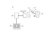
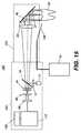
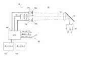
図1に、本発明の一実施形態に係る撮像装置10、特にその光学系の基本構成を示す。この装置10はFIRE法による齲蝕検知装置であり、青色等所要波長域に属する光をその光源12で発生させている。その光はレンズ14等のビーム調光器越しに歯牙20に入射し、図示の通りその歯牙20の平滑面を照明し或いは図示しない咬合面を照明する。それによって発生する光のうちレンズ22越しに白黒カメラ30によって検知されるのは、歯牙20への入射光と同一波長でありその強度から歯牙20の反射率を導出できる後方散乱光と、その入射光によって励起された蛍光である。鏡面反射光は、FIRE法による撮像(FIRE撮像)に際し誤検知(false positive)を発生させうる不要な反射光であるので、それをできるだけ拾わないよう、カメラ30の向きは光源12の向きに対し相応に傾けてある。これによって、鏡面反射光による惑乱効果を受けずに後方散乱光での撮像を行うことが可能になる。[Imaging device]
FIG. 1 shows a basic configuration of an
この図示例では、白黒カメラ30が、付随する色フィルタ(波長領域フィルタ)26及び28のうち一方を介し反射光像を、また他方を介し蛍光像を捉える。処理装置38は、それら反射光像及び蛍光像の画像データを取得及び処理しFIRE像60を生成する。FIRE像60は、診断向けに補強された画像であり印刷出力することやディスプレイ40の画面上に表示させることが可能である。また、FIRE像60のデータを情報記憶装置に送ることや、他所に送って表示させることもできる。 In this illustrated example, the
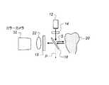
他方、図2にその光学系基本構成を示す別例では、カラーカメラ32を使用しているので歯牙20のフルカラー像を得ることができる。そのフルカラー像を色分解することで歯牙20の反射光像及び蛍光像が得られるので、補助的なフィルタはこの例では一般に不要となる。 On the other hand, in another example showing the basic configuration of the optical system in FIG. 2, the
また、光源12としては、405nm近傍の波長を中心とし青色域及びその周辺で発光するものを使用する。ただ、実用上は、近紫外域から青色域にかけての波長域(約300〜500nm)で発光する光源であれば問題ない。また、その発光素子としては発光ダイオード(LED)を使用する。LEDの個数は1個でも複数個でもよい。レーザ光源を使用することや、キセノンランプ等の広帯域光源に不要波長除去用の色フィルタを付加したものを使用することもできる。更に、光源12からの光は歯牙20への入射前にレンズ14、拡散板13等のビーム調光器によって調光されている。レンズ14は照明の均等化やスポットサイズの制御に役立つ。その上流(下流でもよい)に位置する拡散板13は照明光(例えばLEDビーム)のホットスポットを平滑する。照明光路上に光導波乃至光分配部材、例えば図示しない光ファイバや液体光導波路を配置してもよい。照明光強度は例えば数mW程度とするが、どのようなビーム調光器乃至撮像素子を使用するかに応じより高い又は低い強度にするのが望ましい。 Further, as the
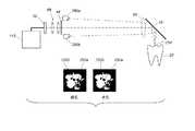
他方、図3にその光学系基本構成を示す別例では、図の上方から光を入射するよう照明用光学系が構成されている。その光はビームスプリッタ34によって方向転換されており、カメラ32はそのビームスプリッタ34越しに到来する光を捉えて撮像するよう配置されている。照明用光学系は、この他にも、複数個の光源を使用し歯牙20の一側面又は複数側面を斜め方向から照明する(図12A参照)、複数個のLED光源が軸対称配置された環状アレイ等のリング状照明器を使用し多方向から照明光を送り均等照明する(図12B参照)、光ファイバ又はその束を介し照明光を供給する(図12C参照)等の構成を採ることができる。 On the other hand, in another example of the basic configuration of the optical system shown in FIG. 3, the illumination optical system is configured so that light is incident from above. The light is redirected by the
撮像用光学系は、図1〜図3中ではレンズ22として示したが、単一レンズ式の構成から多素子レンズ式の構成に至るまで様々な構成にすることができる。歯牙表面には緩慢輪郭部位や急角畝状部位が併存しているので、それを鮮明に撮像するには撮像用光学系の視界深度を十分に深くすべきである。撮像用光学系は、例えば、カメラ側センサ素子の視野をほとんど埋めるサイズになるよう像を形成する。 The imaging optical system is shown as the
白黒カメラ30(図1)又はカラーカメラ32(図2)では、CMOS、CCD等のセンサ素子を使用し撮像を行う。その際、白黒カメラ30を使用する例では、注目波長を透過させる色フィルタ26及び28を適宜挿抜する。光源12が青色光源であるので、反射光撮像用のフィルタ26としては主に青色域を透過させるフィルタを、また蛍光撮像用のフィルタ28としては入射光と異なる波長域(主に緑色域)を透過させるフィルタを使用する。それらのフィルタ26及び28を交互に自動挿抜することで、反射光像と蛍光像をほとんど間をおかずに連続撮影することができる。それらの像は歯牙20の同一部位から得られるので、反射光像データと蛍光像データを互いに正確に位置合わせすることができる。 The monochrome camera 30 (FIG. 1) or the color camera 32 (FIG. 2) performs imaging using a sensor element such as a CMOS or CCD. At this time, in an example in which the
そのうち色フィルタ28の透過域は、所望波長域に亘り蛍光撮像できるよう最適化されている。即ち、歯牙20にて発生する蛍光は可視域内で割合に広いスペクトル分布を呈するが、その帯域は励起光(照明光)の波長域外、具体的には約450〜600nmの帯域であり、ピークを呈するのは一般に約510〜550nmの緑色域内である。従って、フィルタ28としては、得られる蛍光像のエネルギレベルができるだけ高くなるよう、緑色透過フィルタを使用している。カラーカメラ32を使用する実施形態でも、同じ理由で、緑色透過フィルタを介し緑色光を捉えて蛍光撮像を行う。その緑色透過フィルタとしては、カラー撮像の分野で周知の通り、CFA(色フィルタアレイ)上の緑色透過フィルタを使用する。但し、ここで述べた帯域設定は一例であり、可視域内の他の帯域を使用することもできる。 Among them, the transmission region of the
カメラ動作は各像を好適に捉えうるよう適宜調整される。例えば、弱い光である蛍光を捉えねばならない蛍光撮像時には、利得、シャッタ速度及び開口率の調整による露光レベル調整を施す。図2に示す例では、カラーカメラ32内の撮像素子に前置したCFAを用い色フィルタリングを実行することで、反射光像を青色平面上に捉えるのと同時に蛍光像を緑色平面上に捉えること、即ち1回の露光動作で反射光像,蛍光像双方を捉えることができる。 The camera operation is appropriately adjusted so that each image can be properly captured. For example, at the time of fluorescence imaging in which fluorescence, which is weak light, must be captured, exposure level adjustment is performed by adjusting gain, shutter speed, and aperture ratio. In the example shown in FIG. 2, by performing color filtering using a CFA placed in front of the image sensor in the
処理装置38としては、通常はコンピュータワークステーションを使用する。より広く捉えると、カメラ30又は32からの画像取込、それに対する相応の画像処理アルゴリズムの適用、並びにその結果に基づくFIRE像60の生成が可能なものなら、どのような種類の論理制御プロセッサ乃至システムでも処理装置38として使用可能である。処理装置38はローカル配置も撮像部へのネットワーク経由接続も可能である。 As the
図5に、本実施形態におけるFIRE像60の生成手法を例示的に示す。図中の50は歯牙20の緑色蛍光像、52は青色反射光像の例である。前述の通り、反射光像52及びそのデータは、反射光中の鏡面反射光を阻止又は可能な限り抑圧して得られたものであるので、そのことに留意されたい。図中の齲蝕部58、即ち像50、52及び60上の一点鎖線部位では反射光強度が高く且つ蛍光強度が低くなるが、そうした変動分は僅かであるので個々の像50,52から齲蝕部58を見つけ出すのは不可能又は非常に困難である。そこで、処理装置38では、像50,52に係る都合二種類の画像データに対し後述の画像処理アルゴリズムを適用する。その結果得られるFIRE像60上では、歯牙20の齲蝕部健常部間コントラストが強調されているので、齲蝕部58をより容易に視認することができる。 FIG. 5 exemplarily shows a method for generating the
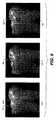
図6に、本実施形態によるコントラスト比向上の効果を、可視白色光像54及び緑色蛍光像52との横並び対比で示す。像52は従来の蛍光撮像法で得られたものである。その進行段階がごく初期である場合、肉眼観察か口内カメラ経由か問わず、白色光像54上では齲蝕部58を周りの健常歯牙組織から見分けることができない。従来の蛍光撮像法で捉えた緑色蛍光像52上では、ごく微かな陰影として齲蝕部58が見えるものの、その視認は非常に困難である。それに対し、本実施形態で得られるFIRE像60上には、その同じ齲蝕部58が、より暗く、より発見しやすいスポットとして写っている。明らかに、FIRE像60の方がコントラストがはっきりしていて、診断上、より有益である。 FIG. 6 shows the effect of improving the contrast ratio according to the present embodiment in a side-by-side comparison with the visible white
[画像処理]
図5及び図6に基づく説明中で述べた通り、反射光像データ及び蛍光像データに基づき歯牙齲蝕部を看取しやすい像を生成するには、それらのデータに対し適宜画像処理を施す必要がある。反射光像データと蛍光像データを結合させて診断用のFIRE像60を生成するのに使用可能な手法は数多くある。例えば本願出願人をその譲受人とする米国特許出願第11/262869号には、スカラー乗算器を用い反射光像データと蛍光像データを結合させて正規化反射光強度・蛍光強度間の差を求める手法が記載されている。[Image processing]
As described in the explanation based on FIGS. 5 and 6, in order to generate an image that makes it easy to see the dental caries based on the reflected light image data and the fluorescence image data, it is necessary to appropriately perform image processing on the data. There is. There are many techniques that can be used to combine the reflected light image data and the fluorescence image data to generate a
また、反射光像データと蛍光像データを結合させる処理に続き更なる画像処理を施すのが有益である。即ち、結合処理で得られたデータを、いわゆる当業者にとり既知の画像処理法を用いたしきい値強調等、相応の処理で調整し、FIRE像60のデータを生成する。そのようにすれば、歯牙齲蝕部健常部間コントラストを更に強調することができる。図7に、本実施形態におけるしきい値強調FIRE像生成用画像処理手順をブロック図の体裁で示す。この手順では、前述の通り反射光像52と蛍光像50を結合させることでFIRE像60を生成した後、注目部位即ち齲蝕部58がよりくっきりと表されるようしきい値処理を施してしきい値像62を生成する。次いで、そのしきい値像62を元のFIRE像60と結合させることで、しきい値強調FIRE像64を生成する。同様に、しきい値検知結果を白色光像54(図6)に重ねることで、その輪郭をくっきりさせ齲蝕部位置をわかりやすくすることができる。 Further, it is beneficial to perform further image processing following the processing of combining the reflected light image data and the fluorescence image data. That is, the data obtained by the combining process is adjusted by a corresponding process such as threshold enhancement using an image processing method known to those skilled in the art to generate
容易にご理解頂けるように、反射光像データと蛍光像データを結合させ齲蝕部がよりはっきりと判る強調された像を得るためのアルゴリズムとしては、多々ある複合画像処理アルゴリズムのうちどれをまた何種類を使用することもできる。得られる像の有用性を高めるには、画像データに対し複数通りの画像処理アルゴリズムを適用できるようにしておくのが望ましい。例えば、得られている反射光像データ及び蛍光像データを調整する画像処理アルゴリズムを複数組用意しておき、使用するアルゴリズム群をオペレータが任意に指定できるようにしておけば、オペレータは、互いに異なる手法でデータ処理された画像データをチェックすることができ、且つ、その形状関連特性の違いや歯牙表面上の部位の違いに応じて処理された画像から好適に、齲蝕による損傷を読み取ることができる。 As can be easily understood, there are many complex image processing algorithms to combine the reflected light image data and the fluorescence image data to obtain an enhanced image with more clearly seen caries. Types can also be used. In order to increase the usefulness of the obtained image, it is desirable that a plurality of image processing algorithms can be applied to the image data. For example, if a plurality of sets of image processing algorithms for adjusting the obtained reflected light image data and fluorescent image data are prepared and the operator can arbitrarily specify the algorithm group to be used, the operators are different from each other. The image data processed by the technique can be checked, and the damage caused by the caries can be preferably read from the processed image according to the difference in the shape-related characteristics and the difference in the part on the tooth surface. .
強調すべきことに、本発明で画像のコントラストを強調できるのは反射光像データと蛍光像データを併用しているためであり、そうした効果があることは蛍光像データしか使用しない従来手法に対する長所である。無論、蛍光像データしか使用しない従来手法でも、例えばカメラやそのフィルタの波長領域応答特性といった諸特性に応じ蛍光像データを変換等する画像処理によって、そのデータを最適化することができる。例えば、前掲の特許文献12に記載の手法でもこの種の最適化、即ちカメラの応答特性に基づく蛍光像データの変換が行われる。しかしながら、それらの従来手法では、後方散乱による反射光像データ中の画像情報を付加することの有益性が看過されている。 It should be emphasized that the contrast of the image can be enhanced in the present invention because the reflected light image data and the fluorescence image data are used in combination, and such an effect is an advantage over the conventional method using only the fluorescence image data. It is. Of course, even in the conventional method using only fluorescent image data, the data can be optimized by image processing that converts the fluorescent image data according to various characteristics such as the wavelength region response characteristics of the camera and its filter. For example, the technique described in the above-mentioned
[他の実施形態]
本発明に係る方法には更に数多くの実施形態がある。その一つは、偏光素子を使用し反射光像、蛍光像又はその双方のコントラストを高める実施形態である。既知の通り、高度な構造化組成を有しているエナメル質は入射光の偏向状態に敏感である。非特許文献1等にも記載の通り、偏向光は歯牙撮像感度を高める上で有用である。[Other Embodiments]
There are many more embodiments of the method according to the invention. One of them is an embodiment in which a polarizing element is used to increase the contrast of a reflected light image, a fluorescent image, or both. As is known, enamel having a highly structured composition is sensitive to the polarization state of incident light. As described in
これは、入射光の偏向状態が鏡面反射光ではよく保存されるが後方散乱光では脱偏向即ちランダム化されるためである。例えば、入射光がs偏向光なら鏡面反射光もs偏向光になるが、後方散乱光はs偏向成分及びp偏向成分を併含する光になる。このように入射光の偏向状態に対する反応が違うため、反射光に含まれる不要な鏡面反射光を偏光器及び検光器で除去して後方散乱光のみを捉えることができる。 This is because the deflection state of incident light is well preserved in specular reflection light but depolarized or randomized in backscattered light. For example, if the incident light is s-polarized light, the specularly reflected light is also s-polarized light, but the backscattered light is light that contains both the s-polarized component and the p-polarized component. As described above, since the response to the deflection state of incident light is different, unnecessary back-reflected light included in the reflected light can be removed by the polarizer and the analyzer, and only the backscattered light can be captured.
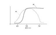
図4Aに、本発明の他の実施形態に係る撮像装置10を示す。この装置10は、図1〜図3に示した基本構成を拡張し、偏光器42その他の補助光学部品を付加した構成を採っている。偏光器42は照明光の入射光路上にあり、入射光はこの偏光器42によって直線偏向されている。歯牙20からの像形成光(像を担持する光)が回送される光路(回送光路)上には、鏡面反射光を抑圧する手段として検光器44(省略可)が設けられている。この偏光器検光器対は偏光素子として機能するので、回送光路経由でカメラ30,32に達する反射光の主成分は後方散乱光となる。後方散乱光に係る画像データは、本発明に従い、蛍光像データと好適に結合させることができる。また、歯牙20からの回送光路上にあるロングパスフィルタ15は、紫外光や短波長の可視光、例えば約405±40nmを中心とする青色域及びより短波長の光を減衰させ、より長波長の光を透過させる。青色光で蛍光(通常は緑色域内波長例えば約550nmを中心波長とする光)を励起する際には、このフィルタ15によって青色光の影響を抑えることができる。また、このフィルタ15で短波長の光が抑圧されるため、反射光像を得るための光源12として白色光源を使用することができる。図24に、波長領域におけるフィルタ15の応答曲線96と白色光のスペクトル分布曲線98(破線)の間の大まかな関係を示す。 FIG. 4A shows an
また、図4Cに示すように、互いにその発光波長域が違う複数個の光源12を併用するようにしてもよい。この例では、光源12のうち一方が例えば約450〜700nmの波長域で発光する白色光撮像用の白色光源であり、他方が例えば300〜500nmの範囲内にすっぽり収まる狭い波長域で発光する蛍光励起用の短波長光源、具体的には紫外LEDである。バンドパスフィルタ17は、その短波長光源に発する光の帯域を狭め、蛍光像への光学的クロストークを抑えている。 Further, as shown in FIG. 4C, a plurality of
光源12を複数個備える構成では、各光源12を個別に点消灯させることで、反射光像と蛍光像を別々のタイミングで得ることができる。図4Cに示した例なら、白色光源12を点灯させることで、カメラ32その他のセンサで反射光像乃至白色光像を捉えることができる。そのときは、他方の紫外LED12は消灯させておく。その状態から白色光源12を消灯させ紫外LED12を点灯させると蛍光像を捉えることができる。 In the configuration including a plurality of
例えば図25に示す撮像プローブ104では、そのトグルスイッチ83を操作することで、トグルスイッチポジションに応じた像をディスプレイ40上に表示させることができる。具体的には、スイッチ83を図の上部に記載のポジションにすると蛍光像120を撮影でき、下部に記載のポジションにすると反射光像122を撮影できる。 For example, in the
これに代え、撮像装置10内のセンサ例えばカメラ32と論理制御回路との間の通信等を通じ、同様の点消灯動作を自動実行させることもできる。その場合、単体のカメラ32乃至センサで複数種類の像を得ることができる。 Instead, the same lighting / extinguishing operation can be automatically executed through communication between a sensor in the
図4Bに、その偏光素子を偏向ビームスプリッタ18に置き換えた例を示す。偏向ビームスプリッタは偏光ビームスプリッタとも称される部品である。図中の偏向ビームスプリッタ18は像形成光に対し好適にも偏光器及び検光器の双方として機能するので、図示例はよりコンパクトな構成になる。照明光及び像形成光の光路をなぞるとこの偏向ビームスプリッタ18の機能が判る。まず、光源12から実質的に無偏向の照明光が入射してくると、偏向ビームスプリッタ18はそのうちのp偏向成分(図中の破線)を透過させ、s偏向成分を歯牙方向に反射させる。歯牙20はその光を後方散乱させる。偏向ビームスプリッタ18は、脱偏向しているその後方散乱光に対し上記同様に作用し、s偏向成分を反射する一方p偏向成分を透過させる。こうして生じたp偏向光は、ロングパスフィルタ15によって濾波された後、カラーカメラ32によって検知され又は図1に示した色フィルタのうち相応のものを介し白黒カメラ30によって検知される。鏡面反射光はs偏向光であるので偏向ビームスプリッタ18によって実質的に除去され、カメラ30,32にはほとんど到達しない。 FIG. 4B shows an example in which the polarizing element is replaced with a
こうして偏向光で照明するとコントラストがよりはっきりした像が得られるが、図4A及び図4Bから読み取れるようにその分は光量が損なわれる。従って、こうした形態で偏向照明光を使用するときはその光源12として高輝度光源を使用すべきである。偏向照明光を使用することは、特に反射光像データの取得に有益であるだけでなく、画像コントラストの強調や鏡面反射光影響分の影響につながるので蛍光像データの取得にも有益である。 When illuminated with deflected light in this way, an image with a clearer contrast can be obtained, but the amount of light is lost as can be read from FIGS. 4A and 4B. Therefore, when using polarized illumination light in such a form, a high-intensity light source should be used as the
偏光器42としては特許文献9(発明者:Perkins et al.)に記載のワイヤグリッド偏光器を使用するのが望ましい。これは米国ユタ州オーレム所在のMoxtek Inc.等が市販しており、その角度応答及び色応答が良好で且つ青色域全体に亘り比較的透過性がよい。従って、図4Aに示した構成であれば偏光器42、検光器44又はその双方をワイヤグリッド偏光器とするのが望ましく、図4Bに示した構成であれば偏向ビームスプリッタ18を市販のワイヤグリッド偏向ビームスプリッタとするのが望ましい。 As the
このように、本実施形態に係る方法は、十分な強度を有する光を入射したとき歯牙組織から返ってくる反射光及び蛍光を併用し、その歯牙にある齲蝕部を従来よりも優れた精度及び鮮明度で示すようにしている点で、従来の非侵襲的蛍光撮像型齲蝕検知法より優れた手法である。即ち、背景技術の欄で説明済の手法では、蛍光のみで像を形成しているためそのコントラスト比が低く齲蝕部を鮮明に表すことができないが、本発明に係る方法ならばよりコントラスト比が高い像を得ることができ、診断医はその像からより容易に齲蝕部を見つけることができる。 As described above, the method according to the present embodiment uses both reflected light and fluorescence returned from the tooth tissue when light having sufficient intensity is incident, and the caries portion on the tooth has an accuracy superior to that of the prior art. This method is superior to the conventional noninvasive fluorescence imaging type caries detection method in that it is shown by the definition. That is, in the method described in the background art section, since the image is formed only by the fluorescence, the contrast ratio is low and the caries portion cannot be clearly expressed. A high image can be obtained, and the diagnostician can find the caries more easily from the image.
加えて、蛍光のみで像を形成する従来手法と異なり、本実施形態の方法による像からは、ごく初期段階の齲蝕をも見つけ出すことができる。検知能力がこのように高まったのは、ごく初期段階の齲蝕でも後方散乱光なら検知可能な強度になることを利用したためである。その検知能力向上によって、蛍光撮像法の有用性が高まりその症状の進行を反転可能な段階での齲蝕検知が容易になるため、齲蝕部充填等の修復的処置を執る必要性が減る。 In addition, unlike the conventional method of forming an image only with fluorescence, it is possible to find a very early stage caries from the image obtained by the method of this embodiment. The reason why the detection capability is increased in this way is that it is possible to detect the intensity of backscattered light even in the very early stage of caries. The improved detection capability increases the usefulness of the fluorescence imaging method and facilitates caries detection at a stage where the progression of the symptoms can be reversed, thereby reducing the need for repairing treatment such as caries filling.
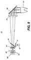
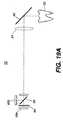
図9に、本発明の更に他の実施形態に係る撮像装置10を示す。これは、偏向ビームスプリッタ18からの偏向光をテレセントリック視野レンズ24に入射させる実施形態である。まず、光源12としては、歯牙20を励起し十分強い蛍光を発生させることができるよう、例えば青色域で発光する光源を使用する。その光源12で発生した照明光は、レンズ14越しに、一方の偏向成分を透過させ他方を反射する偏向ビームスプリッタ18に入射する。図示例では、p偏向成分が偏向ビームスプリッタ18を透過して捨てられる一方、s偏向成分は偏向ビームスプリッタ18にて反射され、視野レンズ24及び転向ミラー46等の反射面(省略可)により歯牙方向へと案内される。歯牙20からの反射光は鏡面反射成分及び後方散乱成分を含んでいるが、鏡面反射では偏向状態が変わらないので照明光がs偏向であれば鏡面反射成分もs偏向になり、その成分は偏向ビームスプリッタ18によって光源方向に反射されることとなる。他方、前述の通り後方散乱反射ではある程度の脱偏向が生じるので、反射光のうちの後方散乱成分にはp偏向の成分が含まれている。そのp偏向成分は偏向ビームスプリッタ18を透過し、検光器44(省略可)によって更に調光された後、撮像レンズ66によって色フィルタ56越しにセンサ68例えばカメラに送られる。この図には示していないが、歯牙20からの回送光路上にロングパスフィルタを設けてもよい。また、本実施形態で色フィルタ56を使用しているのは、光源12からの光で蛍光を励起させる際に、励起波長域の光を遮り蛍光だけをセンサ68で検知させるためである。即ち、センサ68に内蔵されているCFAの応答があまり急峻でなく、光源12に発する励起光を十分阻止できないためである。 FIG. 9 shows an
テレセントリック視野レンズ24を使用していることも本実施形態の長所である。テレセントリック光学系では視界深度内の倍率が一定になるので、歯牙20のように高低差の激しい輪郭を有する物体を近距離から撮像するためのレンズとしては、この種のレンズ24が特に相応しい。それによって遠近歪みが小さくなる。なお、図9では単体レンズの記号で表してあるが、レンズ24は多素子レンズにすることができる。光源12の発光波長は、白色、青色、緑色、赤色、近赤外等、相応の波長にすることができる。図10に例示する撮像装置10のように、転向ミラー46を廃しその代わりの偏向ビームスプリッタ18を像形成光の光路上に配してもよい。その位置は、視野レンズ24を用いる場合はそれと歯牙20の間とし、用いない場合は歯牙20のすぐ手前とする。光源12が偏向ビームスプリッタ18越しに照明光を入射するよう配置されているので、その有無によらず視野レンズ24を照明光が通ることはない。偏向ビームスプリッタ18及び検光器44があるので鏡面反射光はやはり捨てられる。 The use of the
図11に、本発明の更に他の実施形態に係る撮像装置10をブロック図により示す。本実施形態では互いに別体な2個の光源12a及び12bを使用する。光源12a及び12bの発光波長は互いに同一の波長でも別々の波長でもよい。光源12a及び12bによる歯牙20の照明は互いに同時でも別々のタイミングでもよい。像形成光が通る光路上、視野レンズ24と歯牙20の間に偏向ビームスプリッタ18が配されているので、転向機能及び偏向機能を共に提供することができる。 FIG. 11 is a block diagram illustrating an
図12Aに、図11中の光源12a,12bそれぞれに対応するよう偏光器42a,42bを設けた例を示す。この例の偏向ビームスプリッタ18は転向ミラーで置き換えることもできるが、光源12a,12b及びそれに対応する偏光器42a,42bによって偏向照明光が生成されているので、偏向ビームスプリッタ18を用いることで画質をより高めることができる。図12Bに、LED個数を更に増やし歯牙20等の被写体に達する光量を増した例を示す。上記同様、それらのLEDは白色LEDでも青色LEDでもその組合せでもよいが、照明光が均等化されるよう歯牙20等の被写体から見て対称に配置すべきである。 FIG. 12A shows an example in which polarizers 42a and 42b are provided so as to correspond to the
図12Cに、その照明器の構成を更に変形し、LED等の光源で発生させた光をファイバ束によって歯牙20等の被写体に送るようにした例を示す。この例で使用されている4組の光ファイバ束49a〜49dのうち2組(49a及び49b)は被写体への白色光供給に使用されており、直線偏向された照明光が得られるようその出射面の面前には都合2個の偏光器42a及び42bが配されている。他の2個のファイバ束49c及び49dは、被写体を励起し蛍光を発生させるための光源、例えば青色LED、紫外LED等の光源につながっている。 FIG. 12C shows an example in which the configuration of the illuminator is further modified and light generated by a light source such as an LED is sent to a subject such as a
図19Aに本発明の更に他の実施形態を示す。本実施形態の撮像プローブは2個のセンサ68a及び68bと1個のダイクロイックミラー48を備えている。本実施形態では、そのダイクロイックミラー48が分波器として機能し、センサ68a及び68bに互いに異なる波長域の反射光を供給する。ダイクロイックミラー48は、例えば可視域(440〜650nm)に属する光を透過させ、紫外域(<400nm)や近赤外域(>700nm)に属する光を反射する。こうした構成の撮像プローブは、齲蝕検知以外の用途、例えば歯牙色調調整や軟組織撮像にも使用できる。図19Bに示す通り、センサ68a,68bで得られる像を互いに別々のディスプレイ142に送るようにしてもよい。 FIG. 19A shows still another embodiment of the present invention. The imaging probe of this embodiment includes two
本実施形態では、図25に示すようにライブ動画表示される画像を白色反射光像122と蛍光像122との間で切り替えることができる。即ち、オペレータは、蛍光像を参照して歯牙20の齲蝕をスクリーニングすることや、種々の目的で白色光像を参照し歯牙20の状態を診断することができる。プローブ104にはその切替のためのスイッチ83が設けられており、オペレータはライブ動画の表示モードを随意に指定することができる。スイッチ83はユーザインタフェース上の他の部位に設けることもできるが、プローブ104上に設けるのであれば2段階ボタンスイッチにするとよい。例えば、無押し状態なら白色光像のライブ動画を表示させ、半押し状態なら蛍光像のライブ動画を表示させ、全押し状態なら表示中の白色光像,蛍光像双方をキャプチャし静止画として保存する。 In the present embodiment, as shown in FIG. 25, an image displayed as a live video can be switched between the white reflected
スイッチ83は、マルチポジションスイッチ、例えば5個のスイッチポジションを有するジョイスティックスイッチにすることもできる。それらのスイッチポジションには、論理制御プロセッサ140によって実行されるプログラムに従い、互いに別の機能が割り当てられている。例えば、スイッチポジションを1にするとモードがライブ白色光像モード・ライブ蛍光像モード間で切り替わり、2にすると静止画がキャプチャされ、3にすると歯列グラフィクス上で所定方向に沿って歯牙別ナビゲーションが実行され、4にすると逆方向に沿って同様のナビゲーションが実行され、5にすると歯牙注目面を頬側面、咬合面及び舌側面のなかから指定することができる、というように、歯牙/注目面指定用の簡便なインタフェースが提供される。 The
図26に、スイッチ83をそれと一体の構成要素として使用する撮像装置10を示す。ここではスイッチ83として3ポジションのものを使用する例を示してある。論理制御プロセッサ140は、スイッチ83のポジションがaのときには白色光源を点灯させて白色光像を捉えディスプレイ142の画面上にライブ表示させる。ポジションがbのときには青色光源を点灯させて蛍光像を捉えディスプレイ142の画面上にライブ表示させる。ポジションがcのときには反射光像及び蛍光像の双方を静止画キャプチャする。なお、この図ではディスプレイ142を複数個使用できるが、図25に示した通り、単一のディスプレイ40上に複数個のウィンドウを開き個々の像を対応するウィンドウ内に表示させてもよい。また、この図では単一のセンサ68で双方の像を捉えているが、図19A及び図19Bに示した通りセンサを複数個(68a,68b)使用してもよい。 FIG. 26 shows the
この撮像装置10に搭載されている電子回路は高速な回路であるので多重化処理を実行でき、従って1個のセンサ68で白色光像及び蛍光像を高速撮影し表示させることができる。即ち、光源12a,12bのうち捉えたい像に対応する方の光源を点灯させその像をセンサ68で捉えるという手順を、高速で実行することができる。また、図19A及び図19Bに示した通りセンサを2個(68a,68b)備える構成では、センサ及びそれに関連する部材が複数個必要になるものの、白色光像,蛍光像共に、より容易に連続撮影することができる。それに加え、情報処理を高速で行える回路を備えているので、本発明に係るFIRE像を連続的に生成、更新して表示させることができる。 Since the electronic circuit mounted on the
更に、その電子回路及びソフトウェアが高速であるため、オペレータ向けに二種類のライブ動画を表示させることができる。センサの個数が1個でも2個でも同様である。その発光波長が互いに異なる複数個のLEDを交互に点消灯させて撮像すれば、ライブ動画間のクロストークも抑えられる。オペレータにしてみれば、そうして表示される二種類のライブ動画、即ち白色光像及び蛍光像を互いに見比べ、それらの像中の罹患疑い部位に診断を下すことができる。また、交互に得られる白色光像及び蛍光像にたいし後述する画像処理ユーティリティを適用することで、罹患疑い部位を自動強調表示させることもできる。 Furthermore, since the electronic circuit and software are high-speed, two types of live moving images can be displayed for the operator. The same is true whether the number of sensors is one or two. If a plurality of LEDs having different emission wavelengths are alternately turned on and off to capture an image, crosstalk between live moving images can be suppressed. The operator can compare the two types of live moving images displayed in this way, that is, the white light image and the fluorescent image, and make a diagnosis on a suspicious site in those images. Further, by applying an image processing utility to be described later to the white light image and the fluorescence image obtained alternately, it is possible to automatically highlight the affected part.
また、従来の口内カメラ及び齲蝕検知用撮像装置では、プローブを動かすと逆方向にライブ動画が動いてしまう。これは、撮像レンズの使用個数が1個だと像が倒立像になるためであるが、これは幾つかの光学的手法で克服し正立像を得ることができる。その手法の一つは図21に示す如く像転送法を使用する手法である。この手法では、撮像レンズ222の働きで被写体220(歯牙20)の中間像224が生じ、更に撮像レンズ226の働きでその中間像224の最終像228が生じる。被写体220の倒立像である中間像224を更に倒立させているので、最終像228の向きは被写体220(歯牙20)の向きと同じになり、従って最終像228が動く方向もプローブを動かした方向と同方向になる。また、転向ミラーを付加して像の向きを変える手法や、ソフトウェア的に画像データを操作し像の向きを補正する手法もある。最後の手法では、取り立てて光学部品を付加しなくても、オペレータ向けの画面上に正立像を表示させることができる。 Further, in the conventional intraoral camera and the caries detection imaging apparatus, when the probe is moved, the live video moves in the opposite direction. This is because if the number of imaging lenses used is one, the image becomes an inverted image, but this can be overcome by several optical methods to obtain an upright image. One of the methods is a method using an image transfer method as shown in FIG. In this method, an
更に、センサ使用個数が1個(68のみ)の構成には、捉える像の種類を変えるたびにフィルタ例えばロングパスフィルタ56を挿抜しなければならないという難点がある。例えば、蛍光撮像時にはフィルタ56が必須だが反射光撮像時には光路上から動かさねばならない。フィルタ56を動かすための部品があるとシステム構成が複雑になり、その撮像装置のハンドヘルド化にはとりわけ不都合である。この難点を解消するには、フィルタ56の特性を適切に設定すると共に、センサ68の色バランスを適宜調整するようにすればよい。まず、図28Bに示すように、反射光像を得るための白色光源(例えば12a)の発光波長域は広く(曲線98)、蛍光励起用光源たる紫外LED(例えば12b)の発光波長域は狭い(曲線232)。こうした場合には、そのカットオフ波長が青色域中心付近、例えば460nmにあるロングパスフィルタ(フィルタ曲線96)を、フィルタ56としてセンサ68の面前に固定配置するのが適切である。蛍光撮像時には、このフィルタ56は、紫外励起光に由来する成分を好適に阻止する一方、約550nmを中心波長とする蛍光信号を透過させる。白色光での反射光撮像時には、白色光源12aに発する光のうち青色域にエネルギ的な減衰が生じるものの、減衰するのは460nm未満の帯域であり、460nm超の帯域に属する光はかなりの程度透過していく。そのため、得られる白色光像中の青色成分は若干弱くなるが、これは、青色成分を強調する小規模な色処理で補正することができる。従って、フィルタを動かすための部材を設けることなく、良質な白色光像及び蛍光像を得ることができる。 Furthermore, in the configuration in which the number of sensors used is one (only 68), there is a difficulty in that a filter, for example, the
また、蛍光励起用紫外LED12bに発するエネルギはその大半が405nm近傍の波長域に集中しているが、そのスペクトル曲線232の極長波長部分(>460nm)にも多少はエネルギが分布しているので、その僅かなエネルギがロングパスフィルタ56を透過し蛍光信号とクロストークする可能性がある。この不要なクロストークをなくすには、図28Aの如きスペクトル応答(曲線234)を呈する図示しないショートパスフィルタを、LED12bの下流に付加すればよい。或いは、図27に示すように、そのショートパスフィルタとしてダイクロイックビーム結合器230を使用してもよい。このビーム結合器230は、白色光源12aからの光を反射させて歯牙20に向かわせる一方、蛍光励起用光源たる紫外LED12bからの光(この例では約405nmに公称ピーク値がある光)に対しては、図28Aに示した応答特性(曲線234)を有するローパスフィルタとして作用する。 Further, most of the energy emitted to the fluorescence
[合焦及びオートフォーカス]
図23A及び図23Bに、それぞれ、一実施形態に係るオートフォーカス機能付撮像装置を示す。これらの図では、その煩雑化を避けるため白色光源や蛍光励起用光源(例えばLED)の図示を省略してある。図中、光源250a,250bはレンズ一体型のLEDであり、そのコリメーティングレンズにより光源250a,250bの像252a,252bが歯牙表面上の光軸交点256に形成される(符号同順)。ただ、図23Aに示す通り、プローブのポジションが正しくないと(離焦していると)像252a,252bは重なり合わない。図23Cに、これを利用し焦点を合わせる手順を示す。この図には、交点256に対する位置が違う歯牙20が列記されている。図中左側の例では交点256が歯牙20より上にあり、右側の例では下にある。どちらの例も離焦状態である。中央の例では歯牙20に合焦している。オペレータとしては、像252aと像252bが重なり合う位置へとプローブを動かすことで、合焦状態にすることができる。その状態でシステムに対し指示すると、その像を好適に撮影することができる。更に、同じ原理でオートフォーカス機能を提供することもできる。それには、いわゆる当業者にとり周知の光検知法に従い像252a及び252bの位置を検知及び追跡し、両者が重なったらセンサ68乃至カメラを起動し像を捉えさせるソフトウェアを、制御回路110上で又はそれと連携して実行させればよい。[Focus and auto focus]
FIG. 23A and FIG. 23B each show an imaging device with an autofocus function according to an embodiment. In these drawings, in order to avoid complication, a white light source and a fluorescence excitation light source (for example, LED) are not shown. In the drawing,
図23Bは図23Aの簡略版であり、レンズ一体型LEDを1個(250a)しか使用する必要がない。この例では、画面中心及び光軸を示す十字線254即ち標的指示子を画面上に表示させている。像252aがその十字線254の交点に一致していれば、そのプローブは合焦状態にある。更に、像252aの位置を追跡するソフトウェアを使用すれば、十字線254やそれに類する手段も必要なくなる。 FIG. 23B is a simplified version of FIG. 23A, and only one lens-integrated LED (250a) needs to be used. In this example, a
[OCT(光干渉断層撮像)法を用いる実施形態]
OCT法は、他の従来手法では撮像できない歯牙組織等の組織を干渉計測原理で撮像する非侵襲的撮像法である。図13に、本発明の一実施形態に係りFIRE撮像及びOCT撮像を併用する撮像装置10を示す。図中のOCTシステム80は、LED等の低コヒーレンシー光源160に発する光を二通りの光路に送出する。その光路長が既知の基準アーム164と、歯牙20に向かう標本アーム76である。アーム164,76からの反射光を干渉計162にて再結合させ、その干渉状況を調べることで、標本の内部構造を知ることができる。[Embodiment using OCT (Optical Coherence Tomography) Method]
The OCT method is a non-invasive imaging method that images tissues such as tooth tissues that cannot be imaged by other conventional methods based on the principle of interference measurement. FIG. 13 shows an
光源12、偏向ビームスプリッタ18、視野レンズ24、転向ミラー82、撮像レンズ66及びセンサ68はFIRE撮像機能を提供するための部材であり、光路上に前述の如く配置されている。OCT撮像器70は、それらFIRE撮像用の部材が並ぶ光路の一部にOCT走査光を送出する。即ち、OCTシステム80にて発生させた光を、まず、標本アーム76及びコリメーティングレンズ74を介し、走査素子72例えばガルバノメータに送り、次いで、走査レンズ84を含む光学系を介し、可視光を透過させ近赤外以上の長波長光を反射するダイクロイックミラー78に送り、更に、視野レンズ24に送る。なお、非テレセントリックなOCT走査では視野レンズ24は不要である。歯牙20から戻ってくる光は同じ光路を辿って干渉計162に至り基準アーム164からの光と再結合される。 The
OCT走査では入射ビーム進行面沿いに被写体断面が二次元走査されるので、相応の画像合成論理に従い隣接切断線間で走査結果を結合させることにより、標本構造例えば歯牙組織を表す立体像(多次元像)を合成することができる。その像には歯牙表面下部分も現れる。多次元像合成処理はデータ取得兼処理用電子回路166及びコンピュータ168で実行する。 In OCT scanning, the cross section of the object is two-dimensionally scanned along the incident beam traveling plane. By combining the scanning results between adjacent cutting lines according to the corresponding image synthesis logic, a three-dimensional image representing a specimen structure such as a tooth structure (multi-dimensional) Image). The lower part of the tooth surface also appears in the image. The multidimensional image composition processing is executed by the data acquisition / processing
OCT撮像器70から出射される光は連続波低コヒーレンシー/広帯域光である。その光源としては、スーパールミネッセントダイオード、ダイオードポンプド固体結晶光源、ダイオードポンプド希土類ドープドファイバ光源等を使用できる。本実施形態では近赤外光、例えばその波長が約1310nmの光で撮像を行う。 The light emitted from the
このように、歯牙表面下状態を探知可能であるためOCT走査は非常に有力なツールであるが、自明な通り、そうした詳細な情報を全ての歯牙の全ての沿面部位について求める必要があるわけでもない。寧ろ、注目部位を個別に指定しその部位だけをOCT法で撮像した方が有利である。即ち、図14Aに示すような歯牙20の表示画像上で、オペレータ例えばOCT走査を担当する診断医が、注目部位90を指定するようにするとよい。この指定は、例えば図1〜図3に示した処理装置38及びディスプレイ40によって提供されるオペレータインタフェースツールを使用し、オペレータがディスプレイ40の画面上で注目部位90の範囲を指定することで実行する。使用できるツールとしては、コンピュータ用のマウスや、ポインタとなりうるある種の電子スタイラス等がある。その上で、図13に示した撮像装置10の所要部分、例えばそのプローブを注目部位90に接近させてOCT走査を実行する。図14Bに、得られたOCTデータに基づき生成される画像92の例を示す。 In this way, OCT scanning is a very powerful tool because it can detect the subsurface state of the tooth, but it is obvious that such detailed information needs to be obtained for all creeping parts of all teeth. Absent. Rather, it is more advantageous to individually designate a site of interest and image only that site using the OCT method. That is, it is preferable that an operator, for example, a diagnostician in charge of OCT scanning, designates the
[プローブ実施形態]
本発明の撮像装置10を構成する部材は、様々な形態でパッケージングすることができる。その一つは、検査を担当する歯科医や技師が容易に扱えるようコンパクトなパッケージングである。図15に、本発明の一実施形態に係るハンドヘルド歯牙撮像装置100を示す。そのハンドル102は破線で示す如き輪郭を有しており、また光源12、センサ68並びにそれに付随する種々の照明用・撮像用光路形成部品を収容している。そのハンドル102に取り付けられているプローブ104は、単なるカバーにすることもできるが、この例では歯牙撮像に相応しい位置関係になるようレンズ24及び転向ミラー46を支持している。また、制御回路110は装置100の動作を制御する回路であり、スイッチ、メモリ、論理制御回路等で構成されている。例えば、光源12を点消灯させるためのスイッチ等、装置構成部材制御用のスイッチのみ又はその集まりのみで、制御回路110を構成してもよい。検知機能制御及び画像データ取得用の論理が組み込まれたマイクロプロセッサを、プローブ104に内蔵させ又は接続して制御回路110としてもよい。図1〜図3に示した処理装置38に制御回路110の機能を担わせることもできる。装置100の動作を管理する高度な論理制御回路や、検知部材、情報記憶部材等を、制御回路110に組み込んでもよい。そして、制御回路110は、無線インタフェース136との接続を介し外部装置、例えばコンピュータワークステーションやサーバと通信することができる。その通信は、図18に示すように無線で行うことができる。この図の撮像システム150では、オペレータからの指示、例えば制御ボタン押下等に応じ装置100が撮像を実行する。得られた像は論理制御プロセッサ140、例えばコンピュータワークステーション、サーバ、専用マイクロプロセッサベースシステム等に送信され、ディスプレイ142の画面上に表示される。こうして撮像装置100を無線接続すると、有線接続無しで処理装置38に画像データを送ることができる。データ伝送用の無線インタフェースとしては、Bluetooth(登録商標)等、様々なものを使用することができる。[Probe embodiment]
The members constituting the
また、この歯牙撮像装置100の構成は、大人用サイズ、児童用サイズ等、患者の種類に応じて変えることができる。サイズ切替にはプローブ104を換装可能型にすると都合がよい。また、歯牙20の種類や撮像方向に応じプローブ104の構成を切り替えることもできる。プローブ104は、使い捨て型にも接触部品滅菌再利用型にもすることができる。撮像法の種類に対しプローブ104を適合させることもできる。例えば、プローブ104の換装によって付随する光学部品を換装することで、使用する撮像法の種類に応じ、広角撮像プローブや単一歯牙専用小面積撮像プローブにすることができる。そして、撮像法の種類に応じ、プローブ104に1個又は複数個のオプションレンズを挿入乃至装着して使用することもできる。 The configuration of the
プローブ104は、歯牙20を乾かし画質を高める装置として使用することもできる。特に、蛍光撮像を実施する際には歯牙表面が乾いていた方がよい。そのため、本実施形態では、図15に示す如くプローブ104にチューブ106が設けられている。そのチューブ106によって形成される出口を介し、加圧ガス源81内のガス例えば加圧空気を送り出すことで、歯牙20の表面を乾かすことができる。プローブ104自体を通気トンネル即ち加圧空気用の導管としてもよいし、チューブ106をプローブ104とは別の配管にしてもよい。 The
図16に、ハンドヘルド撮像装置100にディスプレイ112を設けた例を示す。このディスプレイ112は液晶ディスプレイ、有機LEDディスプレイ等のディスプレイであり、図示の通りハンドル102に連結されている。その画面上に画像108が表示されるので、歯科医や技師は、その画像108を見ながらプローブ104を動かし歯牙20に対して適当な位置にすることができる。この構成では、白色光源を用いて捉えた像をディスプレイ112上に表示させるので、その白色光源は常時点灯状態である。但し、オペレータからFIRE撮像が指示されたとき(例えば装置100上のスイッチやキーボード上のキーが押下等されたとき)には、白色光像を撮影した上で白色光源を消灯させ、青色LED等の光源を点灯させて蛍光像を撮影し、それによって白色光像及び蛍光像が揃った後に再び白色光源を点灯させる。また、このディスプレイ112に限らず別体のディスプレイにも、ナビゲーション用の白色光像を表示させることができる。別体ディスプレイに白色光像を表示させれば、患者が自分の患部を見ることができる。 FIG. 16 shows an example in which the
また、撮像の際、歯牙20の表面を基準位置とすることで、プローブ104の位置を歯牙20に直面させることができる。それによって撮像系の配置が安定し光学的作業距離が固定されるので、その質及び安定性の高い像が得られる。歯牙20のすぐ面前にプローブ104を配置することは、前述の通り光軸沿い距離が短くないとうまく行えないOCT撮像に際しても特に有益である。 Further, the position of the
ただ、歯牙20の様々な面を撮像するには、図22に示すように、プローブ104内に転向ミラー19等を設けることが必要になろう。そうしたミラー19を設けると、その鏡面が不意に曇ってしまうことがある。この問題の克服には、口内カメラの分野で使用されている種々の手法を使用できる。第1の手法は、口内温度近傍までミラー19を加熱する手法である。この手法には、加熱素子及びそれを駆動するための電流源を付加しなければならないという問題がある。第2の手法は、鏡面処理によって曇り止め皮膜を形成する手法である。この手法であれば、新たな部材を追加する必要はない。この他、鏡面に曇り止めフィルムを接着する手法もある。 However, in order to image various surfaces of the
そして、図11及び図12A〜図12Cに示した実施形態では、ビーム整形用光学素子に通すことなく直接に、光源12a,12bからの光で歯牙20を照明している。光源12a,12bたるLEDの出射光は広角散開するのが普通であり、そのため図22に示す如く出射光中のかなりの部分がプローブ内面に射突してしまう。即ち、図示のような広角光線240a、240b及び240cではプローブ内面への射突が生じる。このとき、プローブ内面が吸光性であると、射突した光はその面によって吸収されるので歯牙20に届かなくなる。そこで、本実施形態では、プローブ内面に入射した光がその面によって反射されるよう、従っていずれは歯牙20に届くよう、プローブ内面を反射性にしてある。これによって得られる効果は二種類ある。一つめは、僅かな吸収損失分を除き全ての光が歯牙20に届くので効率が高いという効果である。二つめは、歯牙20がより均等に照明されるという効果である。プローブ内面が平坦な反射面ならそのプローブは光パイプとして機能するので、光は空間的且つ方向的にまとまり、歯牙20に対する照明が均等になる。ただ、プローブ内面に(部分的な)湾曲があるとその面の反射性により照明光がホットスポットを呈する可能性がある。これを避けるにはプローブ内面を散光性にすればよい。プローブ内面が散光性であれば、その面に湾曲があっても照明光がホットスポットを呈することはない。それでいて効率の高さは維持される。なお、プローブ内面を反射性や散光性にする手段としては、その面に相応の被覆を施す等、本件技術分野で周知の手段を使用することができる。 In the embodiment shown in FIGS. 11 and 12A to 12C, the
[画像処理ソフトウェア]
別々の手段で取得した画像同士を関連づける処理、例えばX線撮像装置で得られた画像と本発明の撮像装置10で得られる画像のように別途取得した画像同士を結合させる処理は、検知結果に含まれる誤検知(false positive)や見逃し(false negative)を減らすのに役立つ。図1〜図3に示した処理装置38で実行される画像処理ソフトウェアには、それらの像が同じ撮像装置10で得られたものか、それとも撮像装置10で得られた像と他の装置で得られた像の組合せなのかによらず、同じ歯牙20を捉えた複数の像を互いに関連づける機能がある。[Image processing software]
The process of associating images acquired by different means, for example, the process of combining images acquired separately such as an image acquired by an X-ray imaging apparatus and an image acquired by the
図17に、その出自が異なる複数種類の画像及びそれらを処理する手順をブロック図形式で示す。蛍光像120、反射光像122及び白色光像124は前述の通り撮像装置10で取得したものであり、X線像130はそれとは別にX線撮像装置で取得したものである。画像関連づけソフトウェア132は、それらの像のうち複数種類を採用し、それらのデータを然るべく関連づけることで、採用した像の合成像134を生成する。生成された像134は自動診断ソフトウェアにより処理又は表示されるので、どの歯牙のどの部位に問題があるかをその結果から知ることができる。例えば、オペレータから撮像が指示され更に歯牙番号が(或いは更に統合対象画像の種類やその取得元が)指定されると、処理装置38に搭載されているソフトウェアは、その指示に基づき合成像134を生成して表示させる。 FIG. 17 shows in block diagram form a plurality of types of images with different origins and the procedure for processing them. The
この画像関連づけ機能を使用するメリットの一つは、正確な診断をより下しやすい像134が得られることである。例えば白色光像124は、歯牙汚れ(ステイン)、アマルガム等のように齲蝕部と見間違えやすい罹患部乃至処置部も読み取れる点でひときわ有益であるが、前述の通り、照明光が白色だと特に初期段階の齲蝕部をうまく発見できないことが多い。従って、白色光像124を蛍光像120、X線像130等のうち一種類又は複数種類と組み合わせることは、歯牙状態についての有用な情報を得る上で有益である。同様に、図示されている四種類の像120〜130のなかから任意に二種類を指定し、指定した像を画像関連づけソフトウェア132によって結合させることで、より正確な診断につながる合成像130を得ることができる。 One of the merits of using this image association function is that an
また、前述の通り偏向を利用して鏡面反射光を分離させてはいるものの、それでもなお鏡面反射の影響が像に現れることがある。画像処理ソフトウェアには、こうした残留鏡面反射を画像処理で抑圧乃至削減する機能もある。即ち、データフィルタリングを施すことや、別の撮像法で得られた情報(図17参照)を利用することによって、データ中の不要な残留鏡面反射を抑えることができる。また、照明光強度の変化に対する鏡面反射光強度の変化速度は、他の原因による光のそれと異なっている。従って、照明光の強度を変えて同一歯牙を繰り返し撮像することで、鏡面反射分を補償することもできる。 In addition, although the specular reflection light is separated using the deflection as described above, the influence of the specular reflection may still appear in the image. The image processing software also has a function of suppressing or reducing such residual specular reflection by image processing. That is, unnecessary residual specular reflection in the data can be suppressed by performing data filtering or using information obtained by another imaging method (see FIG. 17). Further, the change speed of the specular reflection light intensity with respect to the change of the illumination light intensity is different from that of the light caused by other causes. Therefore, the specular reflection can be compensated by changing the intensity of the illumination light and repeatedly imaging the same tooth.
画像処理ソフトウェアには、更に、得られた画像を補強し疑い部位例えば白点を自動ハイライトする、という重要な機能がある。図20に、そのための画像処理の手順をフローチャートにより示す。画像処理ソフトウェアは、まず白色光像及び蛍光像を読み込んで(ステップ202)そのコンテンツを色平面毎に解析する(ステップ204)。次いで、それらの像の解析結果に基づき様々な画像処理アルゴリズム、例えば色づけ、コントラスト強調及び細分化(一部は画像処理との関連で既述)を適用することによって、像を補強する(ステップ206及び208)。更に、色平面毎の色情報に基づき各部位の性質を調べる画像処理アルゴリズムを用い、疑い部位を自動強調例えばハイライトさせる(ステップ210)。そして、歯科医にとって有用な歯牙情報、例えばサイズ、形状及び疑い部位の状態を抽出して表示させる(ステップ212)。 The image processing software further has an important function of reinforcing the obtained image and automatically highlighting a suspicious portion such as a white spot. FIG. 20 is a flowchart showing an image processing procedure for that purpose. The image processing software first reads a white light image and a fluorescent image (step 202) and analyzes the contents for each color plane (step 204). The images are then augmented by applying various image processing algorithms such as coloring, contrast enhancement and subdivision (partially described in connection with image processing) based on the analysis results of those images (step 206). And 208). Further, an suspicious part is automatically highlighted, for example, highlighted using an image processing algorithm for examining the properties of each part based on color information for each color plane (step 210). Then, tooth information useful for the dentist, for example, the size, shape, and state of the suspicious part is extracted and displayed (step 212).
以上詳述した通り、本発明には様々な実施形態がある。また、上掲の実施形態に対し変形乃至置換を施した形態等でも、本発明を実施することができる。いわゆる当業者であれば、そうした変形乃至置換を、前述の通り本発明の技術的範囲内で、即ち別紙特許請求の範囲の記載から逸脱することなく、施すことができる。 As detailed above, the present invention has various embodiments. In addition, the present invention can be implemented in a form obtained by modifying or replacing the above-described embodiment. A so-called person skilled in the art can make such modifications and substitutions within the technical scope of the present invention as described above, that is, without departing from the description of the appended claims.
例えば、使用できる光源の種類は数多い。従って、その実施形態で使用する撮像用のセンサ例えばカメラの種類に応じた光源を選び、光源12として使用することができる。また、蛍光を励起させるための光源12の他に更に光源12を設けること、即ち都合複数個の光源12に発する光で複数の像を得ることができる。例えば、図8に示すように、光源16a及び16bを有する複雑な構成のアセンブリを、光源12として使用することもできる。この例では、蛍光励起に適する波長及び強度で発光する光源16aとは異なるタイミングで、照明光発生用の光源16bを作動させる。光源16bから発せられる照明光は、例えば後方散乱光による反射光撮像に適する波長及び強度にしてもよいし、多色光(例えば白色光)による撮像に適する波長及び強度にしてもよい。後者の場合、得られた多色像(例えば白色光像)をFIRE像と並べて表示させれば、汚れた部位や石灰化不全が生じている部位等のように齲蝕部と見間違えやすい部位を、より読み取りやすくなる。白色光像それ自体、後方散乱反射によるデータを含んでいるので、白色光像データ及び蛍光像データからFIRE像を生成することができる。また、照明光や像形成光の光路には、様々な形態の補助光学系を設けることができる。例えば、様々な種類の補助光学部品を、撮像時に歯科医や技師が歯牙20に被せられるようにしておくとよい。そうした補助光学部品を使用することで、例えば、光源、検知素子等を適正に位置決めすることや、撮像に際する患者の不快感を軽減することができる。 For example, there are many types of light sources that can be used. Therefore, an imaging sensor used in the embodiment, for example, a light source corresponding to the type of camera can be selected and used as the
このように、本発明に係る装置及び方法によれば、後方散乱現象と蛍光現象を併用することとしたため、その進行段階が初期か後期かを問わず齲蝕を検知することができる。以下に、付記として本発明の構成の例を示す。
(付記1)
(a)歯牙の反射光撮像に使用される第1波長域の光、並びに蛍光撮像に当たり歯牙の励起に使用される第2波長域の光を発生させる少なくとも1個の光源と、
(b)その光の入射光路上に配置されており、光源に発する光のうち第1偏向状態の光を歯牙に入射させ、また歯牙からの光のうち第2偏向状態即ち第1偏向状態に対し直交する偏向状態の光を回送光路経由でセンサに送る偏向ビームスプリッタと、
(c)歯牙から回送光路へ送られてきた第2偏向状態の光をセンサに送り像を形成するレンズと、
(d)回送光路上で第2波長領域の光を減衰させつつ第1波長領域の光を透過させるロングパスフィルタと、
(e)センサを作動させて蛍光像又は反射光像の画像データを取得しその像のライブ動画表示又は静止画キャプチャを可能にする論理制御回路と、
を備える歯牙撮像装置。
(付記2)
付記1記載の歯牙撮像装置であって、更に、第1波長域の光を反射させ第2波長域の光を透過させるダイクロイックビーム結合器を備え、その透過光を上記入射光路に送る歯牙撮像装置。
(付記3)
付記1記載の歯牙撮像装置であって、更に、そのポジションによって論理制御回路に指示を与えるスイッチを備える歯牙撮像装置。
(付記4)
付記1記載の歯牙撮像装置であって、上記センサが、第1波長域の光に係る反射光撮像及び第2波長域の光に係る蛍光撮像を交互実行する歯牙撮像装置。
(付記5)
付記4記載の歯牙撮像装置であって、反射光像及び蛍光像を互いに別のディスプレイ上に同時表示させる歯牙撮像装置。
(付記6)
付記4記載の歯牙撮像装置であって、反射光像及び蛍光像を同一ディスプレイの互いに別のウィンドウ内に同時表示させる歯牙撮像装置。
(付記7)
付記1記載の歯牙撮像装置であって、更に、第2波長領域の光を調光するショートパスフィルタを備える歯牙撮像装置。
(付記8)
付記7記載の歯牙撮像装置であって、そのショートパスフィルタをダイクロイックビーム結合器として機能させる歯牙撮像装置。
(付記9)
付記1記載の歯牙撮像装置であって、上記ロングパスフィルタのカットオフ波長が青色域中心付近にある歯牙撮像装置。
(付記10)
付記1記載の歯牙撮像装置であって、更に、上記センサで捉えられた白色光像を表示するディスプレイを備える歯牙撮像装置。
(付記11)
付記10記載の歯牙撮像装置であって、対応する画像データから白色光像を生成するに当たりその青色域成分を増量する歯牙撮像装置。
(付記12)
付記1記載の歯牙撮像装置であって、第1波長域の光、第2波長域の光又はその双方をファイバ束を介して入射する歯牙撮像装置。
(付記13)
付記3記載の歯牙撮像装置であって、上記スイッチがマルチポジションスイッチである歯牙撮像装置。
(付記14)
付記3記載の歯牙撮像装置であって、上記スイッチがジョイスティックスイッチである歯牙撮像装置。
(付記15)
(a)オペレータが操作してその位置を決めるハンドル部と、
(b)ハンドル部から分離可能且つ歯牙近傍に配置可能なプローブ部と、
(c)ハンドル部内、プローブ部内又はその双方にかけて配置された補助光学系と、
を備え、その補助光学系が、
(i)歯牙の反射光撮像に使用される第1波長域の光を発生させる第1光源と、
(ii)蛍光撮像に当たり歯牙の励起に使用される第2波長域の光を発生させる第2光源と、
(iii)第1及び第2光源からの入射光路上に配置されており、光源からの光のうち第1偏向状態の光を歯牙に入射させ、また歯牙からの光のうち第2偏向状態即ち第1偏向状態に対し直交する偏向状態の光を回送光路経由でセンサに送る偏向ビームスプリッタと、
(iv)歯牙から偏向ビームスプリッタ経由で回送光路に送られてきた第2偏向状態の光をセンサに送り像を形成するレンズと、
(v)回送光路上で第2波長領域の光を減衰させるロングパスフィルタと、
(vi)センサを作動させて蛍光像又は反射光像の画像データを取得しその像のライブ動画表示又は静止画キャプチャを可能にする論理制御回路と、
を有する歯牙撮像装置。
(付記16)
付記15記載の歯牙撮像装置であって、上記プローブ部の内側に反射面がある歯牙撮像装置。
(付記17)
付記15記載の歯牙撮像装置であって、上記プローブ部の内側に散光面がある歯牙撮像装置。
(付記18)
(a)歯牙の撮像に使用される第1波長域の入射光を発生させる第1光源と、
(b)歯牙からの光を回送光路経由で画像データ取得用のセンサに送り像を形成するレンズと、
(c)そのレンズに光を送る第2光源と、
(d)同じくレンズに光を送る第3光源と、
を備え、歯牙表面に合焦しているときに第2光源からの光と第3光源からの光がレンズの焦点近傍で重なる歯牙撮像装置。
(付記19)
付記18記載の歯牙撮像装置であって、上記第1、第2又は第3光源がLEDである歯牙撮像装置。
(付記20)
(a)歯牙の撮像に使用される第1波長域の入射光を発生させる第1光源と、
(b)歯牙から回送光路に送られてきた光を光軸沿いに画像データ取得用のセンサに送り像を形成するレンズと、
(c)そのレンズに光を送る第2光源と、
(d)撮像で得られた歯牙の像に重ね、光軸を示す標的指示子及び第2光源による照明位置を表示するディスプレイと、
を備え、合焦時には光軸に対し第2光源の照明位置が揃う歯牙撮像装置。
(付記21)
(a)歯牙の反射光撮像に使用される第1波長域の光、並びに蛍光撮像に当たり歯牙の励起に使用される第2波長域の光を、ある光路沿いに歯牙に入射する少なくとも1個の光源と、
(b)その光路上で、歯牙からの光のうち第1波長域に属する反射光を第1センサに送り、歯牙からの他の光を第2センサに送る分波器と、
(c)その光路上に配置されており、分波器を経由した光で第1及び第2センサ上に歯牙の像を形成するレンズと、
(d)センサを作動させて蛍光像又は反射光像の画像データを取得しその像のライブ動画表示又は静止画キャプチャを可能にする論理制御回路と、
を備える歯牙撮像装置。
(付記22)
付記21記載の歯牙撮像装置であって、上記分波器がダイクロイックビームスプリッタである歯牙撮像装置。
(付記23)
(a)歯牙の反射光撮像に使用される第1波長域の入射光を第1光源によって発生させるステップと、
(b)蛍光撮像に当たり歯牙の励起に使用される第2波長域の入射光を第2光源により発生させるステップと、
(c)反射光像又は蛍光像を捉えるステップと、
(d)反射光像、蛍光像又はその双方をライブ動画として表示させ又はその静止画キャプチャを可能にするステップと、
を有する歯牙撮像方法。
(付記24)
(a)歯牙の撮像に使用される第1波長域の入射光を第1光源によって発生させるステップと、
(b)歯牙からの光を回送光路に送りその光路上のレンズで画像データ取得用のセンサ上に像を形成するステップと、
(c)第2光源からレンズへと光を送るステップと、
(d)第3光源からレンズへと光を送るステップと、
(e)第2光源からの光ビームと第3光源からの光ビームがレンズの焦点近傍で重なっていることを検知するステップと、
を有し、歯牙表面への合焦を上記重なりの検知で検知する歯牙撮像方法。
(付記25)
(a)歯牙の撮像に使用される第1波長域の入射光を第1光源によって発生させるステップと、
(b)歯牙からの光を回送光路に送りその光路上のレンズで画像データ取得用のセンサ上に像を形成するステップと、
(c)第2光源からレンズへと光を送るステップと、
(d)撮像で得られた歯牙の像に重ね、光軸を示す標的指示子及び第2光源による照明位置を表示させるステップと、
を有し、光軸に対する第2光源照明位置の位置揃いを以て合焦と見なす歯牙撮像方法。As described above, according to the apparatus and method of the present invention, since the backscattering phenomenon and the fluorescence phenomenon are used in combination, caries can be detected regardless of whether the progressing stage is the initial stage or the late stage.Below, the example of a structure of this invention is shown as an additional note.
(Appendix 1)
(A) at least one light source that generates light in a first wavelength range used for reflected light imaging of a tooth and light in a second wavelength range used for excitation of the tooth in fluorescence imaging;
(B) Arranged on the incident light path of the light, the light in the first deflection state of the light emitted from the light source is incident on the tooth, and the light from the tooth enters the second deflection state, that is, the first deflection state. A deflecting beam splitter that sends light in a deflected state perpendicular to the sensor to the sensor via a forward light path;
(C) a lens that sends light in the second deflection state sent from the tooth to the sending light path to the sensor to form an image;
(D) a long-pass filter that transmits light in the first wavelength region while attenuating light in the second wavelength region on the forwarding light path;
(E) a logic control circuit that activates a sensor to acquire image data of a fluorescent image or a reflected light image and enables live video display or still image capture of the image;
A tooth imaging device comprising:
(Appendix 2)
The tooth imaging apparatus according to
(Appendix 3)
The tooth imaging apparatus according to
(Appendix 4)
The tooth imaging apparatus according to
(Appendix 5)
The tooth imaging device according to appendix 4, wherein the reflected light image and the fluorescence image are simultaneously displayed on different displays.
(Appendix 6)
The tooth imaging apparatus according to appendix 4, wherein the reflected light image and the fluorescence image are simultaneously displayed in different windows of the same display.
(Appendix 7)
The tooth imaging apparatus according to
(Appendix 8)
The tooth imaging apparatus according to appendix 7, wherein the short-pass filter functions as a dichroic beam coupler.
(Appendix 9)
The tooth imaging apparatus according to
(Appendix 10)
The tooth imaging apparatus according to
(Appendix 11)
The tooth imaging apparatus according to
(Appendix 12)
The tooth imaging apparatus according to
(Appendix 13)
The tooth imaging apparatus according to appendix 3, wherein the switch is a multi-position switch.
(Appendix 14)
The tooth imaging apparatus according to appendix 3, wherein the switch is a joystick switch.
(Appendix 15)
(A) a handle portion that is operated by an operator to determine its position;
(B) a probe part separable from the handle part and capable of being arranged in the vicinity of the tooth;
(C) an auxiliary optical system disposed in the handle portion, the probe portion, or both;
The auxiliary optical system is
(I) a first light source for generating light in a first wavelength range used for reflected light imaging of a tooth;
(Ii) a second light source that generates light in a second wavelength region that is used for excitation of teeth upon fluorescence imaging;
(Iii) It is arranged on the incident light paths from the first and second light sources, makes light in the first deflected state out of the light from the light sources incident on the teeth, and in the second deflected state out of the light from the teeth, that is, A deflecting beam splitter that sends light in a deflected state orthogonal to the first deflected state to a sensor via a forward light path;
(Iv) a lens that sends light in the second deflection state sent from the tooth to the sending optical path via the deflection beam splitter to the sensor to form an image;
(V) a long pass filter for attenuating light in the second wavelength region on the forward light path;
(Vi) a logic control circuit that activates a sensor to acquire image data of a fluorescent image or a reflected light image and enables live video display or still image capture of the image;
A tooth imaging device having
(Appendix 16)
The tooth imaging apparatus according to
(Appendix 17)
The tooth imaging apparatus according to
(Appendix 18)
(A) a first light source that generates incident light in a first wavelength region used for imaging of a tooth;
(B) a lens for sending light from a tooth to a sensor for acquiring image data via a sending light path;
(C) a second light source that sends light to the lens;
(D) a third light source that also sends light to the lens;
And a tooth imaging apparatus in which the light from the second light source and the light from the third light source overlap in the vicinity of the focal point of the lens when focused on the tooth surface.
(Appendix 19)
The tooth imaging apparatus according to
(Appendix 20)
(A) a first light source that generates incident light in a first wavelength region used for imaging of a tooth;
(B) a lens that forms an image by sending light transmitted from the tooth to the optical path along the optical axis to an image data acquisition sensor;
(C) a second light source that sends light to the lens;
(D) a display that displays the illumination position of the target indicator indicating the optical axis and the second light source superimposed on the tooth image obtained by imaging;
And a tooth imaging device in which the illumination position of the second light source is aligned with the optical axis at the time of focusing.
(Appendix 21)
(A) At least one of light in the first wavelength range used for reflected light imaging of a tooth and light in the second wavelength range used for excitation of the tooth in fluorescence imaging is incident on the tooth along a certain optical path. A light source;
(B) On the optical path, a duplexer that sends reflected light belonging to the first wavelength region among the light from the teeth to the first sensor and sends other light from the teeth to the second sensor;
(C) a lens that is disposed on the optical path and forms an image of a tooth on the first and second sensors with light passing through the duplexer;
(D) a logic control circuit that activates a sensor to acquire image data of a fluorescent image or a reflected light image and enables live video display or still image capture of the image;
A tooth imaging device comprising:
(Appendix 22)
The tooth imaging apparatus according to appendix 21, wherein the duplexer is a dichroic beam splitter.
(Appendix 23)
(A) generating incident light in a first wavelength region used for imaging reflected light of a tooth by a first light source;
(B) generating incident light in a second wavelength range used for excitation of teeth upon fluorescence imaging by a second light source;
(C) capturing a reflected light image or a fluorescent image;
(D) displaying the reflected light image, the fluorescent image or both as a live video, or enabling the still image capture;
A method for imaging a tooth.
(Appendix 24)
(A) generating incident light in a first wavelength range used for imaging a tooth by a first light source;
(B) sending light from the teeth to the forward optical path and forming an image on the sensor for acquiring image data with a lens on the optical path;
(C) sending light from the second light source to the lens;
(D) sending light from the third light source to the lens;
(E) detecting that the light beam from the second light source and the light beam from the third light source overlap in the vicinity of the focal point of the lens;
And a tooth imaging method for detecting focusing on the tooth surface by detecting the overlap.
(Appendix 25)
(A) generating incident light in a first wavelength range used for imaging a tooth by a first light source;
(B) sending light from the teeth to the forward optical path and forming an image on the sensor for acquiring image data with a lens on the optical path;
(C) sending light from the second light source to the lens;
(D) superimposing on the image of the tooth obtained by imaging and displaying the target indicator indicating the optical axis and the illumination position by the second light source;
And a tooth imaging method in which the second light source illumination position with respect to the optical axis is considered to be in focus.
10,100 撮像装置、12,12a,12b,16a,16b,160,250a,250b 光源、13 拡散板、14,22,66,74 レンズ、15,17,26,28,56 フィルタ、18 偏向ビームスプリッタ、19,46 転向ミラー、20,220 被写体(歯牙)、24 視野レンズ、30,32 カメラ、34 ビームスプリッタ、38 処理装置、40,112,142 ディスプレイ、42,42a,42b 偏光器、44 検光器、48,78 ダイクロイックミラー、49a〜49d ファイバ束、50,120 蛍光像、52,122 反射光像、54,124 白色光像、58 齲蝕部、60 FIRE像、62 しきい値像、64 しきい値強調FIRE像、68,68a,68b センサ、70 OCT撮像器、72 走査素子、76 標本アーム、80 OCTシステム、81 ガス源、82 ミラー、83 スイッチ、84 走査レンズ、90 注目部位、92 OCT像、96 フィルタ曲線、98 白色光曲線、102 ハンドル、104 プローブ、106 チューブ、108,252a,252b 像、110 制御回路、130 X線像、132 画像関連づけソフトウェア、134 合成像、136 無線インタフェース、140 論理制御プロセッサ、150 撮像システム、162 干渉計、164 基準アーム、166 データ取得兼処理用電子回路、168 コンピュータ、202〜212 ステップ、222,226 撮像レンズ、224 中間像、228 最終像、230 ビーム結合器、232,234 曲線、240a〜240c 光線、254 十字線、256 交点。 10, 100 imaging device, 12, 12a, 12b, 16a, 16b, 160, 250a, 250b light source, 13 diffuser plate, 14, 22, 66, 74 lens, 15, 17, 26, 28, 56 filter, 18 deflected beam Splitter, 19, 46 Turning mirror, 20, 220 Subject (tooth), 24 Field lens, 30, 32 Camera, 34 Beam splitter, 38 Processing unit, 40, 112, 142 Display, 42, 42a, 42b Polarizer, 44 Inspection Optical device, 48, 78 Dichroic mirror, 49a-49d Fiber bundle, 50, 120 Fluorescent image, 52, 122 Reflected light image, 54, 124 White light image, 58 Caries, 60 FIRE image, 62 Threshold image, 64 Threshold enhancement FIRE image, 68, 68a, 68b sensor, 70 OCT imager, 72 scanning element, 76 specimen arm, 80 OCT system, 81 gas source, 82 mirror, 83 switch, 84 scanning lens, 90 region of interest, 92 OCT image, 96 filter curve, 98 white light curve, 102 handle, 104 probe, 106 Tube, 108, 252a, 252b image, 110 control circuit, 130 X-ray image, 132 image association software, 134 composite image, 136 wireless interface, 140 logic control processor, 150 imaging system, 162 interferometer, 164 reference arm, 166 data Acquisition and processing electronics, 168 computer, 202-212 steps, 222, 226 imaging lens, 224 intermediate image, 228 final image, 230 beam combiner, 232, 234 curve, 240a-240c rays, 2, 4 crosshairs, 256 intersection.
Claims (3)
Translated fromJapanese(b)前記歯牙からの、反射され放射された光を検出する少なくとも1つのセンサと、
(c)前記少なくとも1個の光源からの光の光路上に設けられ、前記少なくとも1個の光源からの光を偏光させ前記歯牙に入射させる少なくとも1つの偏光器と、
(d)回送光路上かつ前記少なくとも1つのセンサの前に配置され、前記歯牙からの像形成光を前記少なくとも1つのセンサに送る検光器と、
(e)前記回送光路上に配置され、前記歯牙からの像形成光を前記センサに送り、偏光された光の一部分から像を形成するレンズと、
(f)前記回送光路上に配置され、前記第2波長域の光を減衰させつつ前記第1波長域の光を透過させるロングパスフィルタと、
(g)前記センサを作動させ、ライブ動画又は静止画である、蛍光像、反射光像、又は前記蛍光像及び前記反射光像の結合のいずれかの画像データを取得して表示する論理制御回路と、
を備える歯牙撮像装置。(A) at least one light source for generating light of a first wavelength range of light, and a second wavelength band that is used for excitation ofAh or a tooth fluorescence imaging for use in reflected light imaging of the tooth,
(B) at least one sensor for detecting reflected and emitted light from the tooth;
(C) at least one polarizer that is provided on an optical path of light from the at least one light source and that polarizes light from the at least one light source and enters the teeth;
(D) an analyzer disposed on the forward light path and in front of the at least one sensor, for sending image forming light from the teeth to the at least one sensor;
(E) a lens that is disposed on the routing light path, sends image forming light from the teeth to the sensor, and forms an image from a portion of the polarized light;
(F) the arranged forwarded optical path, a long pass filter transmitting light of the first wavelength range while attenuating light of the second wavelength range,
(G) A logic control circuit that activates the sensor to acquire and display image data of a fluorescent image, a reflected light image, or a combination of the fluorescent image and the reflected light image, which is a live moving image or a still image. When,
A tooth imaging device comprising:
(b)ハンドル部から分離可能且つ歯牙近傍に配置可能なプローブ部と、
(c)ハンドル部内、プローブ部内又はその双方にかけて配置された補助光学系と、
を備え、その補助光学系が、
(i)歯牙の反射光撮像に使用される第1波長域の光を発生させる第1光源と、
(ii)蛍光撮像に当たり歯牙の励起に使用される第2波長域の光を発生させる第2光源と、
(iii)前記少なくとも1個の光源からの光の光路上に設けられ、前記少なくとも1個の光源からの光を前記歯牙に入射させる少なくとも1つの偏光器と、
(iv)回送光路上かつ少なくとも1つのセンサの前に配置され、前記歯牙からの像形成光を前記少なくとも1つのセンサに送る検光器と、
(v)歯牙から前記偏光器経由で回送光路に送られてきた偏向状態の光をセンサに送り像を形成するレンズと、
(vi)回送光路上で第2波長領域の光を減衰させるロングパスフィルタと、
(vii)センサを作動させて蛍光像又は反射光像の画像データを取得しその像のライブ動画表示又は静止画キャプチャを可能にする論理制御回路と、
を有する歯牙撮像装置。(A) a handle portion that is operated by an operator to determine its position;
(B) a probe part separable from the handle part and capable of being arranged in the vicinity of the tooth;
(C) an auxiliary optical system disposed in the handle portion, the probe portion, or both;
The auxiliary optical system is
(I) a first light source for generating light in a first wavelength range used for reflected light imaging of a tooth;
(Ii) a second light source that generates light in a second wavelength region that is used for excitation of teeth upon fluorescence imaging;
(Iii) at least one polarizer that is provided on an optical path of light from the at least one light source and that makes the light from the at least one light source incident on the teeth;
(Iv) even withoutleast Tsu or forward light path is arranged in front of one sensor, a detection optical unit to send the image forming light from the tooth to the at least one sensor,
(V) a lens that forms an image by sending light in a deflected state sent from a tooth through a polarizer to a sending light path to a sensor;
(Vi) a long pass filter for attenuating light in the second wavelength region on the forward light path;
(Vii) a logic control circuit that activates a sensor to acquire image data of a fluorescent image or a reflected light image and enables live video display or still image capture of the image;
A tooth imaging device having
歯牙表面にそれぞれマーカー像を形成するための光を前記視野レンズに送る第3及び第4の光源と、
を備え、
前記論理制御回路は、前記第3の光源により形成されたマーカー像と前記第4の光源により形成されたマーカー像とが重なったことを検出したときに、前記センサを作動させて反射光像又は蛍光像の画像データを取得する、ことを特徴とする請求項1又は2に記載の歯牙撮像装置。A field lens which is provided between the light source and the tooth and focuses the light from the light source on the tooth surface;
A third and a fourth light source for sending light to form amarker image on the tooth surface to the field lens;
With
When the logic control circuit detects that themarker image formed by the third light source overlaps themarker image formed by the fourth light source, the logic control circuit operates the sensor to detect a reflected light image or The tooth imaging apparatus according to claim 1, wherein image data of a fluorescent image is acquired.
Applications Claiming Priority (3)
| Application Number | Priority Date | Filing Date | Title |
|---|---|---|---|
| US11/549,208 | 2006-10-13 | ||
| US11/549,208US7702139B2 (en) | 2006-10-13 | 2006-10-13 | Apparatus for caries detection |
| PCT/US2007/019805WO2008048402A2 (en) | 2006-10-13 | 2007-09-11 | Apparatus for caries detection |
Publications (3)
| Publication Number | Publication Date |
|---|---|
| JP2010505588A JP2010505588A (en) | 2010-02-25 |
| JP2010505588A5 JP2010505588A5 (en) | 2010-10-28 |
| JP5590887B2true JP5590887B2 (en) | 2014-09-17 |
Family
ID=39091883
Family Applications (1)
| Application Number | Title | Priority Date | Filing Date |
|---|---|---|---|
| JP2009532346AExpired - Fee RelatedJP5590887B2 (en) | 2006-10-13 | 2007-09-11 | Tooth imaging device |
Country Status (5)
| Country | Link |
|---|---|
| US (2) | US7702139B2 (en) |
| EP (1) | EP2073689A2 (en) |
| JP (1) | JP5590887B2 (en) |
| CN (2) | CN103142325B (en) |
| WO (1) | WO2008048402A2 (en) |
Cited By (1)
| Publication number | Priority date | Publication date | Assignee | Title |
|---|---|---|---|---|
| KR102057580B1 (en)* | 2018-02-02 | 2019-12-19 | 이준택 | Shade light for medical |
Families Citing this family (158)
| Publication number | Priority date | Publication date | Assignee | Title |
|---|---|---|---|---|
| US11026768B2 (en) | 1998-10-08 | 2021-06-08 | Align Technology, Inc. | Dental appliance reinforcement |
| US9492245B2 (en) | 2004-02-27 | 2016-11-15 | Align Technology, Inc. | Method and system for providing dynamic orthodontic assessment and treatment profiles |
| US8447087B2 (en) | 2006-09-12 | 2013-05-21 | Carestream Health, Inc. | Apparatus and method for caries detection |
| US8270689B2 (en) | 2006-09-12 | 2012-09-18 | Carestream Health, Inc. | Apparatus for caries detection |
| US7702139B2 (en)* | 2006-10-13 | 2010-04-20 | Carestream Health, Inc. | Apparatus for caries detection |
| US8224045B2 (en)* | 2007-01-17 | 2012-07-17 | Carestream Health, Inc. | System for early detection of dental caries |
| US7878805B2 (en) | 2007-05-25 | 2011-02-01 | Align Technology, Inc. | Tabbed dental appliance |
| EP2039288A1 (en)* | 2007-09-18 | 2009-03-25 | Olympus Corporation | Dental observation apparatus |
| US8804111B2 (en)* | 2007-10-04 | 2014-08-12 | Kla-Tencor Corporation | Multichip CCD camera inspection system |
| US8738394B2 (en) | 2007-11-08 | 2014-05-27 | Eric E. Kuo | Clinical data file |
| US7929151B2 (en)* | 2008-01-11 | 2011-04-19 | Carestream Health, Inc. | Intra-oral camera for diagnostic and cosmetic imaging |
| US8866894B2 (en) | 2008-01-22 | 2014-10-21 | Carestream Health, Inc. | Method for real-time visualization of caries condition |
| US8108189B2 (en) | 2008-03-25 | 2012-01-31 | Align Technologies, Inc. | Reconstruction of non-visible part of tooth |
| WO2009139110A1 (en)* | 2008-05-13 | 2009-11-19 | パナソニック株式会社 | Intraoral measurement apparatus and intraoral measurement system |
| US9492243B2 (en) | 2008-05-23 | 2016-11-15 | Align Technology, Inc. | Dental implant positioning |
| US8092215B2 (en) | 2008-05-23 | 2012-01-10 | Align Technology, Inc. | Smile designer |
| US8172569B2 (en) | 2008-06-12 | 2012-05-08 | Align Technology, Inc. | Dental appliance |
| US20120040305A1 (en)* | 2008-09-24 | 2012-02-16 | Denstply International Inc. | Imaging device for dental instruments and methods for intra-oral viewing |
| US8152518B2 (en) | 2008-10-08 | 2012-04-10 | Align Technology, Inc. | Dental positioning appliance having metallic portion |
| EP2395906A4 (en)* | 2009-02-12 | 2017-06-28 | Novartis Ag | Method and apparatus for ocular surface imaging |
| US9241622B2 (en)* | 2009-02-12 | 2016-01-26 | Alcon Research, Ltd. | Method for ocular surface imaging |
| US10603008B2 (en)* | 2009-02-19 | 2020-03-31 | Tessonics Corporation | Ultrasonic device for assessment of internal tooth structure |
| US8292617B2 (en) | 2009-03-19 | 2012-10-23 | Align Technology, Inc. | Dental wire attachment |
| US8570530B2 (en)* | 2009-06-03 | 2013-10-29 | Carestream Health, Inc. | Apparatus for dental surface shape and shade imaging |
| GB0910316D0 (en)* | 2009-06-16 | 2009-07-29 | Univ Manchester | Image analysis method |
| US8768016B2 (en)* | 2009-06-19 | 2014-07-01 | Carestream Health, Inc. | Method for quantifying caries |
| US8765031B2 (en) | 2009-08-13 | 2014-07-01 | Align Technology, Inc. | Method of forming a dental appliance |
| JP2011147757A (en)* | 2009-09-29 | 2011-08-04 | Fujifilm Corp | Medical apparatus and endoscope apparatus |
| CN102596002B (en)* | 2009-10-30 | 2014-12-17 | 卡尔斯特里姆保健公司 | Intraoral camera with liquid lens |
| US20110149058A1 (en)* | 2009-12-21 | 2011-06-23 | Rongguang Liang | Intra-oral camera with polarized and unpolarized light |
| JP5541914B2 (en)* | 2009-12-28 | 2014-07-09 | オリンパス株式会社 | Image processing apparatus, electronic apparatus, program, and operation method of endoscope apparatus |
| US9241774B2 (en) | 2010-04-30 | 2016-01-26 | Align Technology, Inc. | Patterned dental positioning appliance |
| US9211166B2 (en) | 2010-04-30 | 2015-12-15 | Align Technology, Inc. | Individualized orthodontic treatment index |
| BR112012028452A2 (en) | 2010-05-06 | 2016-07-19 | Alcon Res Ltd | Devices and methods for assessing changes in corneal health |
| US9642687B2 (en) | 2010-06-15 | 2017-05-09 | The Procter & Gamble Company | Methods for whitening teeth |
| JP2012053268A (en)* | 2010-09-01 | 2012-03-15 | Canon Inc | Lenticular lens, image forming apparatus and image forming method |
| US20120056993A1 (en)* | 2010-09-08 | 2012-03-08 | Salman Luqman | Dental Field Visualization System with Improved Ergonomics |
| US9436868B2 (en)* | 2010-09-10 | 2016-09-06 | Dimensional Photonics International, Inc. | Object classification for measured three-dimensional object scenes |
| CN102008282B (en)* | 2010-10-29 | 2012-08-08 | 深圳大学 | Number stamp intraoral scanner and oral cavity internal surface topography image real-time reconstructing system |
| US8311302B2 (en) | 2010-12-13 | 2012-11-13 | Carestream Health, Inc. | Method for identification of dental caries in polychromatic images |
| EP2657680A4 (en)* | 2010-12-21 | 2014-01-01 | Panasonic Corp | OPTICAL TOMOGRAPHY IMAGE ACQUISITION DEVICE |
| CN102028555B (en)* | 2010-12-31 | 2012-07-04 | 中国科学院光电技术研究所 | Fluorescent tooth detector |
| CN102613954A (en)* | 2011-01-26 | 2012-08-01 | 卡尔斯特里姆保健公司 | Oral cavity endoscope with polarized light and non-polarized light |
| RU2561867C2 (en)* | 2011-02-15 | 2015-09-10 | Уэйвлайт Гмбх | Device and method for optical coherence tomography |
| KR101223283B1 (en)* | 2011-03-08 | 2013-01-21 | 경북대학교 산학협력단 | Diagnostic display and operating intergrated optical tomography otoscope |
| TWI435704B (en)* | 2011-03-15 | 2014-05-01 | Crystalvue Medical Corp | Oral optical diagnosing apparatus and operating method thereof |
| WO2012126324A1 (en) | 2011-03-21 | 2012-09-27 | Carestream Health, Inc. | Autofocus method using liquid lens |
| US9486141B2 (en)* | 2011-08-09 | 2016-11-08 | Carestream Health, Inc. | Identification of dental caries in live video images |
| JP5796408B2 (en)* | 2011-08-24 | 2015-10-21 | オムロンヘルスケア株式会社 | Oral care device |
| US9403238B2 (en) | 2011-09-21 | 2016-08-02 | Align Technology, Inc. | Laser cutting |
| US9001326B2 (en) | 2011-12-13 | 2015-04-07 | Welch Allyn, Inc. | Method and apparatus for observing subsurfaces of a target material |
| US9375300B2 (en) | 2012-02-02 | 2016-06-28 | Align Technology, Inc. | Identifying forces on a tooth |
| US9220580B2 (en) | 2012-03-01 | 2015-12-29 | Align Technology, Inc. | Determining a dental treatment difficulty |
| KR101530168B1 (en)* | 2012-04-23 | 2015-06-19 | 지멘스 헬쓰케어 다이아그노스틱스 인크. | Biological assay sample analyzer |
| US9414897B2 (en) | 2012-05-22 | 2016-08-16 | Align Technology, Inc. | Adjustment of tooth position in a virtual dental model |
| US20130323671A1 (en)* | 2012-05-30 | 2013-12-05 | Ormco Corporation | Spectral filter for an intra-oral imaging system |
| JP5974640B2 (en)* | 2012-06-01 | 2016-08-23 | ソニー株式会社 | Dental apparatus and information processing apparatus |
| EP4306075A3 (en) | 2012-06-27 | 2024-04-10 | 3Shape A/S | 3d intraoral scanner measuring fluorescence |
| WO2014013950A1 (en) | 2012-07-19 | 2014-01-23 | 独立行政法人 国立長寿医療研究センター | Measurement/display method and measurement/display device for dental plaque, gum and alveolar bone |
| JP6038644B2 (en)* | 2012-12-27 | 2016-12-07 | 株式会社モリタ製作所 | Biological imaging device |
| EP2976619B1 (en) | 2013-03-20 | 2021-11-10 | Siemens Healthcare Diagnostics Inc. | Light and shutter for a sample analyzer |
| US10788678B2 (en) | 2013-05-17 | 2020-09-29 | Excelitas Canada, Inc. | High brightness solid state illumination system for fluorescence imaging and analysis |
| US9675428B2 (en)* | 2013-07-12 | 2017-06-13 | Carestream Health, Inc. | Video-based auto-capture for dental surface imaging apparatus |
| JP6313978B2 (en)* | 2014-01-08 | 2018-04-18 | オリンパス株式会社 | Display method |
| CN103868902B (en)* | 2014-04-03 | 2016-03-30 | 福州大学 | A kind of bioluminescence detection probe |
| TWI539935B (en)* | 2014-05-27 | 2016-07-01 | Metal Ind Res & Dev Ct | Method for establishing dual - wavelength tooth images |
| JP6067625B2 (en)* | 2014-07-02 | 2017-01-25 | 株式会社モリタ製作所 | Biological imaging device |
| US10772506B2 (en) | 2014-07-07 | 2020-09-15 | Align Technology, Inc. | Apparatus for dental confocal imaging |
| TWI563202B (en)* | 2014-08-11 | 2016-12-21 | App Hour Innovation Co Ltd | Auxiliary tool for oral health |
| US9675430B2 (en) | 2014-08-15 | 2017-06-13 | Align Technology, Inc. | Confocal imaging apparatus with curved focal surface |
| JP6349202B2 (en)* | 2014-08-29 | 2018-06-27 | シスメックス株式会社 | Fluorescence detection device, test substance detection device, and fluorescence detection method |
| US10449016B2 (en) | 2014-09-19 | 2019-10-22 | Align Technology, Inc. | Arch adjustment appliance |
| US9610141B2 (en) | 2014-09-19 | 2017-04-04 | Align Technology, Inc. | Arch expanding appliance |
| CN104181142A (en)* | 2014-09-19 | 2014-12-03 | 中国科学院自动化研究所 | Molecular image imaging verification system and method |
| US9744001B2 (en) | 2014-11-13 | 2017-08-29 | Align Technology, Inc. | Dental appliance with cavity for an unerupted or erupting tooth |
| ES2797683T3 (en)* | 2015-01-22 | 2020-12-03 | Neocis Inc | Interactive Guidance and Tamper Detection Arrangements for a Surgical Robotic System |
| US10504386B2 (en) | 2015-01-27 | 2019-12-10 | Align Technology, Inc. | Training method and system for oral-cavity-imaging-and-modeling equipment |
| US10074178B2 (en) | 2015-01-30 | 2018-09-11 | Dental Imaging Technologies Corporation | Intra-oral image acquisition alignment |
| US9844426B2 (en)* | 2015-03-12 | 2017-12-19 | Align Technology, Inc. | Digital dental tray |
| TWI587829B (en)* | 2015-03-30 | 2017-06-21 | 丹美科技有限公司 | Dental plaque detector with camera |
| ES2587883B1 (en)* | 2015-04-27 | 2017-05-09 | Universidade De Vigo | Procedure for the diagnosis of dental demineralization processes |
| CN104887174B (en)* | 2015-06-23 | 2016-06-29 | 哈尔滨工业大学 | The differential photothermal imaging detection System and method for of dental tissue early-stage caries |
| US10248883B2 (en) | 2015-08-20 | 2019-04-02 | Align Technology, Inc. | Photograph-based assessment of dental treatments and procedures |
| EP3347700A4 (en)* | 2015-09-07 | 2019-04-17 | Mobileodt Ltd. | Handheld mobile device for detection of biological evidence |
| JP6150401B2 (en)* | 2015-11-05 | 2017-06-21 | 日商平野株式会社 | Plaque monitor |
| US11554000B2 (en) | 2015-11-12 | 2023-01-17 | Align Technology, Inc. | Dental attachment formation structure |
| US11931222B2 (en) | 2015-11-12 | 2024-03-19 | Align Technology, Inc. | Dental attachment formation structures |
| US11596502B2 (en) | 2015-12-09 | 2023-03-07 | Align Technology, Inc. | Dental attachment placement structure |
| US11103330B2 (en) | 2015-12-09 | 2021-08-31 | Align Technology, Inc. | Dental attachment placement structure |
| JP6562857B2 (en)* | 2016-03-18 | 2019-08-21 | 株式会社吉田製作所 | Optical coherence tomographic image generation apparatus and method of using the same |
| JP2019518936A (en)* | 2016-04-06 | 2019-07-04 | ケアストリーム・デンタル・テクノロジー・トプコ・リミテッド | Intraoral OCT by compressed sensing |
| EP3439535A1 (en)* | 2016-04-06 | 2019-02-13 | Carestream Dental Technology Topco Limited | Hybrid oct and surface contour dental imaging |
| CN105852790A (en)* | 2016-04-26 | 2016-08-17 | 郑洪� | Endoscopic device and endoscope |
| CN109313016B (en)* | 2016-05-31 | 2021-05-11 | 锐珂牙科技术顶阔有限公司 | Intraoral 3D Scanner Using Fluid Segmentation |
| WO2017218947A1 (en) | 2016-06-17 | 2017-12-21 | Align Technology, Inc. | Intraoral appliances with sensing |
| US10383705B2 (en) | 2016-06-17 | 2019-08-20 | Align Technology, Inc. | Orthodontic appliance performance monitor |
| US10507087B2 (en) | 2016-07-27 | 2019-12-17 | Align Technology, Inc. | Methods and apparatuses for forming a three-dimensional volumetric model of a subject's teeth |
| CA3030676A1 (en) | 2016-07-27 | 2018-02-01 | Align Technology, Inc. | Intraoral scanner with dental diagnostics capabilities |
| KR101904830B1 (en)* | 2016-09-21 | 2018-10-11 | 한국광기술원 | Optical imaging system for oral cavity |
| CN106491082B (en)* | 2016-10-11 | 2020-09-18 | 明基智能科技(上海)有限公司 | Three-dimensional profile scanner |
| CN106264476B (en)* | 2016-10-28 | 2024-03-29 | 合肥京东方光电科技有限公司 | Tongue detection equipment |
| CN117257492A (en) | 2016-11-04 | 2023-12-22 | 阿莱恩技术有限公司 | Method and apparatus for dental imaging |
| AU2017366755B2 (en) | 2016-12-02 | 2022-07-28 | Align Technology, Inc. | Methods and apparatuses for customizing rapid palatal expanders using digital models |
| EP3547952B1 (en) | 2016-12-02 | 2020-11-04 | Align Technology, Inc. | Palatal expander |
| WO2018102770A1 (en) | 2016-12-02 | 2018-06-07 | Align Technology, Inc. | Force control, stop mechanism, regulating structure of removable arch adjustment appliance |
| US11026831B2 (en) | 2016-12-02 | 2021-06-08 | Align Technology, Inc. | Dental appliance features for speech enhancement |
| US10548700B2 (en) | 2016-12-16 | 2020-02-04 | Align Technology, Inc. | Dental appliance etch template |
| US10456043B2 (en) | 2017-01-12 | 2019-10-29 | Align Technology, Inc. | Compact confocal dental scanning apparatus |
| US10779718B2 (en) | 2017-02-13 | 2020-09-22 | Align Technology, Inc. | Cheek retractor and mobile device holder |
| WO2018183358A1 (en) | 2017-03-27 | 2018-10-04 | Align Technology, Inc. | Apparatuses and methods assisting in dental therapies |
| US10613515B2 (en) | 2017-03-31 | 2020-04-07 | Align Technology, Inc. | Orthodontic appliances including at least partially un-erupted teeth and method of forming them |
| CN110913956A (en)* | 2017-04-24 | 2020-03-24 | 高露洁-棕榄公司 | Method for monitoring white spots on teeth |
| CN106943193A (en)* | 2017-04-27 | 2017-07-14 | 华中科技大学 | Common location operation guiding system and camera head |
| US11045283B2 (en) | 2017-06-09 | 2021-06-29 | Align Technology, Inc. | Palatal expander with skeletal anchorage devices |
| KR101994522B1 (en)* | 2017-06-14 | 2019-07-01 | 한국광기술원 | Apparatus and method for acquiring diagnostic images of teeth by near-infrared |
| JP7051845B2 (en) | 2017-06-15 | 2022-04-11 | 富士フイルム株式会社 | How to operate a medical image processing device, an endoscope system, and a medical image processing device |
| CN116942335A (en) | 2017-06-16 | 2023-10-27 | 阿莱恩技术有限公司 | Automatic detection of tooth type and eruption status |
| KR102573669B1 (en)* | 2017-06-21 | 2023-09-04 | 코닌클리케 필립스 엔.브이. | Method and device for early caries detection |
| US10639134B2 (en) | 2017-06-26 | 2020-05-05 | Align Technology, Inc. | Biosensor performance indicator for intraoral appliances |
| WO2019002616A1 (en)* | 2017-06-30 | 2019-01-03 | Carestream Dental Technology Topco Limited | Surface mapping using an intraoral scanner with penetrating capabilities |
| US10885521B2 (en) | 2017-07-17 | 2021-01-05 | Align Technology, Inc. | Method and apparatuses for interactive ordering of dental aligners |
| CN111107806B (en) | 2017-07-21 | 2022-04-19 | 阿莱恩技术有限公司 | Jaw profile anchoring |
| CN110996842B (en) | 2017-07-27 | 2022-10-14 | 阿莱恩技术有限公司 | Tooth Staining, Transparency and Glazing |
| EP4278957A3 (en) | 2017-07-27 | 2024-01-24 | Align Technology, Inc. | System and methods for processing an orthodontic aligner by means of an optical coherence tomography |
| US12274597B2 (en)* | 2017-08-11 | 2025-04-15 | Align Technology, Inc. | Dental attachment template tray systems |
| US11116605B2 (en) | 2017-08-15 | 2021-09-14 | Align Technology, Inc. | Buccal corridor assessment and computation |
| US11123156B2 (en) | 2017-08-17 | 2021-09-21 | Align Technology, Inc. | Dental appliance compliance monitoring |
| CN107677641A (en)* | 2017-09-29 | 2018-02-09 | 南京科兴新材料科技有限公司 | A kind of helicobacter pylori diagnostor |
| US12171575B2 (en) | 2017-10-04 | 2024-12-24 | Align Technology, Inc. | Intraoral systems and methods for sampling soft-tissue |
| US10813720B2 (en) | 2017-10-05 | 2020-10-27 | Align Technology, Inc. | Interproximal reduction templates |
| CN111565668B (en) | 2017-10-27 | 2022-06-07 | 阿莱恩技术有限公司 | Substitute occlusion adjusting structure |
| CN111295153B (en) | 2017-10-31 | 2023-06-16 | 阿莱恩技术有限公司 | Dental appliance with selective bite loading and controlled tip staggering |
| CN119235481A (en) | 2017-11-01 | 2025-01-03 | 阿莱恩技术有限公司 | Automatic treatment planning |
| US11534974B2 (en) | 2017-11-17 | 2022-12-27 | Align Technology, Inc. | Customized fabrication of orthodontic retainers based on patient anatomy |
| US11219506B2 (en) | 2017-11-30 | 2022-01-11 | Align Technology, Inc. | Sensors for monitoring oral appliances |
| WO2019112090A1 (en)* | 2017-12-07 | 2019-06-13 | 한국광기술원 | Composite imaging device for structural/functional images of tooth |
| WO2019115364A1 (en)* | 2017-12-12 | 2019-06-20 | Koninklijke Philips N.V. | Method and system for improved measurement of localized oral inflammation using centroid sampling |
| US11432908B2 (en) | 2017-12-15 | 2022-09-06 | Align Technology, Inc. | Closed loop adaptive orthodontic treatment methods and apparatuses |
| US10980613B2 (en) | 2017-12-29 | 2021-04-20 | Align Technology, Inc. | Augmented reality enhancements for dental practitioners |
| US10813727B2 (en) | 2018-01-26 | 2020-10-27 | Align Technology, Inc. | Diagnostic intraoral tracking |
| US11937991B2 (en) | 2018-03-27 | 2024-03-26 | Align Technology, Inc. | Dental attachment placement structure |
| EP3773320B1 (en) | 2018-04-11 | 2024-05-15 | Align Technology, Inc. | Releasable palatal expanders |
| WO2019222135A1 (en) | 2018-05-16 | 2019-11-21 | Benevis Informatics, Llc | Systems and methods for review of computer-aided detection of pathology in images |
| TWI667999B (en)* | 2018-05-17 | 2019-08-11 | 廣達電腦股份有限公司 | Method and device for dynamically adjusting fluorescent imaging |
| EP3846673B1 (en)* | 2018-09-07 | 2022-07-06 | KaVo Dental GmbH | Dental camera handpiece for creating intraoral pictures |
| EP3620100A1 (en)* | 2018-09-07 | 2020-03-11 | Kaltenbach & Voigt GmbH | Dental camera handpiece for creating intraoral pictures |
| CN111820853A (en)* | 2019-04-21 | 2020-10-27 | 万元芝 | Oral imaging device and method |
| JP7444978B2 (en)* | 2019-11-07 | 2024-03-06 | コルゲート・パーモリブ・カンパニー | Multimodal imaging system and method therefor |
| CN110811900B (en)* | 2019-11-28 | 2021-07-27 | 傅建华 | Auxiliary visual periodontal treatment instrument |
| WO2021178529A1 (en)* | 2020-03-05 | 2021-09-10 | Nsv, Inc. | Vision sensor apparatus |
| JP2022055830A (en)* | 2020-09-29 | 2022-04-08 | ロレアル | Method and device for detecting sunscreen agent provided with different cosmetic layers on skin |
| WO2022071254A1 (en)* | 2020-09-29 | 2022-04-07 | L'oreal | Method and apparatus for detecting sunscreen on skin having various cosmetic product layers |
| KR102607619B1 (en)* | 2021-05-20 | 2023-11-29 | 주식회사 디오에프연구소 | 3D scanner and a scanning system including the same |
| CN113288025B (en)* | 2021-06-15 | 2024-10-18 | 麦克奥迪实业集团有限公司 | Novel oral cavity illumination diagnosis device |
| JP2023097973A (en)* | 2021-12-28 | 2023-07-10 | 株式会社タムロン | caries detector |
| KR102826241B1 (en)* | 2022-06-03 | 2025-06-26 | 주식회사 메타플바이오 | Multispectral fluorescence imaging apparatus |
| US12059315B2 (en)* | 2022-09-08 | 2024-08-13 | Enamel Pure | Systems and methods for estimating a trend associated with dental tissue |
| JP2025112525A (en)* | 2024-01-19 | 2025-08-01 | コニカミノルタ株式会社 | Optical property measuring device |
Family Cites Families (38)
| Publication number | Priority date | Publication date | Assignee | Title |
|---|---|---|---|---|
| GB1470760A (en)* | 1973-11-12 | 1977-04-21 | Alphametrics Ltd | Ultraviolet camera system for dental photography and mouth pieces therefor |
| US4290433A (en)* | 1979-08-20 | 1981-09-22 | Alfano Robert R | Method and apparatus for detecting the presence of caries in teeth using visible luminescence |
| US4575805A (en)* | 1980-12-24 | 1986-03-11 | Moermann Werner H | Method and apparatus for the fabrication of custom-shaped implants |
| SE442817B (en)* | 1981-04-01 | 1986-02-03 | Hans Ingmar Bjelkhagen | DEVICE FOR OCCURRANTLY ACHIEVING A DISCRIPTION IN A LUMINISCENCE FOR A TANDY SURFACE |
| US4479499A (en)* | 1982-01-29 | 1984-10-30 | Alfano Robert R | Method and apparatus for detecting the presence of caries in teeth using visible light |
| JP3479069B2 (en)* | 1991-04-29 | 2003-12-15 | マサチューセッツ・インステチュート・オブ・テクノロジー | Method and apparatus for optical imaging and measurement |
| US5570182A (en)* | 1994-05-27 | 1996-10-29 | Regents Of The University Of California | Method for detection of dental caries and periodontal disease using optical imaging |
| US5742700A (en)* | 1995-08-10 | 1998-04-21 | Logicon, Inc. | Quantitative dental caries detection system and method |
| EP0881518B1 (en)* | 1996-02-14 | 2005-11-23 | Dainichiseika Color & Chemicals Mfg. Co. Ltd. | Optical control method and optical controller |
| US6449041B1 (en)* | 1997-07-01 | 2002-09-10 | Lj Laboratories, Llc | Apparatus and method for measuring optical characteristics of an object |
| US5882315A (en)* | 1997-12-23 | 1999-03-16 | Acuson Corporation | Ultrasonic imaging method and image for doppler tissue parameters |
| GB9810471D0 (en)* | 1998-05-16 | 1998-07-15 | Helmet Hund Gmbh | Toothbrush |
| US6522407B2 (en)* | 1999-01-22 | 2003-02-18 | The Regents Of The University Of California | Optical detection dental disease using polarized light |
| US6179611B1 (en)* | 1999-01-22 | 2001-01-30 | The Regents Of The University Of California | Dental optical coherence domain reflectometry explorer |
| NL1012012C2 (en)* | 1999-05-10 | 2000-11-23 | Inspektor Res Systems B V | Method and device for determining caries activity of a carious lesion in a tooth. |
| US6122103A (en)* | 1999-06-22 | 2000-09-19 | Moxtech | Broadband wire grid polarizer for the visible spectrum |
| US6717668B2 (en)* | 2000-03-07 | 2004-04-06 | Chemimage Corporation | Simultaneous imaging and spectroscopy apparatus |
| AU2001281742A1 (en)* | 2000-07-21 | 2002-02-05 | Vir A/S | Coupling elements for surface plasmon resonance sensors |
| US7031034B2 (en)* | 2000-10-02 | 2006-04-18 | Eastman Kodak Company | Articulating camera for digital image acquisition |
| JP4648535B2 (en)* | 2000-11-10 | 2011-03-09 | Hoya株式会社 | Electronic endoscope device |
| WO2002082980A2 (en)* | 2001-04-16 | 2002-10-24 | Lasersight Technologies, Inc. | Stereoscopic measurement of cornea and illumination patterns |
| KR100439756B1 (en)* | 2002-01-09 | 2004-07-12 | 주식회사 인피니트테크놀로지 | Apparatus and method for displaying virtual endoscopy diaplay |
| WO2003068064A1 (en) | 2002-02-12 | 2003-08-21 | Science & Engineering Associates, Inc. | Cancer detection and adaptive dose optimization treatment system |
| AU2003218116A1 (en)* | 2002-03-12 | 2003-09-29 | Beth Israel Deaconess Medical Center | Medical imaging systems |
| US6765719B2 (en)* | 2002-05-21 | 2004-07-20 | The Boeing Company | Multiple field of view telescope |
| US7813787B2 (en)* | 2002-07-31 | 2010-10-12 | Inspektor Research Systems Bv | Dental implement and method for tooth surface inspection |
| US6930770B2 (en)* | 2002-08-08 | 2005-08-16 | Applied Materials, Israel, Ltd. | High throughput inspection system and method for generating transmitted and/or reflected images |
| DE102004001856B4 (en)* | 2003-01-14 | 2019-05-23 | J. Morita Mfg. Corp. | Imaging device for diagnostic purposes |
| US20040202356A1 (en)* | 2003-04-10 | 2004-10-14 | Stookey George K. | Optical detection of dental caries |
| JP4571625B2 (en)* | 2003-05-05 | 2010-10-27 | ディーフォーディー テクノロジーズ エルエルシー | Imaging by optical tomography |
| JP2004344260A (en) | 2003-05-20 | 2004-12-09 | J Morita Tokyo Mfg Corp | Dental optical diagnostic equipment |
| US20040240716A1 (en)* | 2003-05-22 | 2004-12-02 | De Josselin De Jong Elbert | Analysis and display of fluorescence images |
| JP2005069807A (en)* | 2003-08-22 | 2005-03-17 | Matsushita Electric Ind Co Ltd | Tooth surface observation device |
| US20050231717A1 (en)* | 2004-04-16 | 2005-10-20 | Industrial Technology Research Institute | Fluorescence inspection spectrometer |
| US7596253B2 (en) | 2005-10-31 | 2009-09-29 | Carestream Health, Inc. | Method and apparatus for detection of caries |
| US7577284B2 (en) | 2006-04-21 | 2009-08-18 | Carestream Health, Inc. | Optical detection of dental caries |
| US8270689B2 (en)* | 2006-09-12 | 2012-09-18 | Carestream Health, Inc. | Apparatus for caries detection |
| US7702139B2 (en)* | 2006-10-13 | 2010-04-20 | Carestream Health, Inc. | Apparatus for caries detection |
- 2006
- 2006-10-13USUS11/549,208patent/US7702139B2/ennot_activeExpired - Fee Related
- 2007
- 2007-09-11JPJP2009532346Apatent/JP5590887B2/ennot_activeExpired - Fee Related
- 2007-09-11CNCN201210506620.3Apatent/CN103142325B/ennot_activeExpired - Fee Related
- 2007-09-11EPEP07838081Apatent/EP2073689A2/ennot_activeWithdrawn
- 2007-09-11WOPCT/US2007/019805patent/WO2008048402A2/enactiveApplication Filing
- 2007-09-11CNCN200780038030.XApatent/CN101553161B/ennot_activeExpired - Fee Related
- 2010
- 2010-03-15USUS12/723,733patent/US8077949B2/ennot_activeExpired - Fee Related
Cited By (1)
| Publication number | Priority date | Publication date | Assignee | Title |
|---|---|---|---|---|
| KR102057580B1 (en)* | 2018-02-02 | 2019-12-19 | 이준택 | Shade light for medical |
Also Published As
| Publication number | Publication date |
|---|---|
| HK1135878A1 (en) | 2010-06-18 |
| US8077949B2 (en) | 2011-12-13 |
| CN101553161A (en) | 2009-10-07 |
| CN103142325A (en) | 2013-06-12 |
| US20100165089A1 (en) | 2010-07-01 |
| CN103142325B (en) | 2017-03-01 |
| CN101553161B (en) | 2014-03-05 |
| US20080090198A1 (en) | 2008-04-17 |
| WO2008048402A2 (en) | 2008-04-24 |
| EP2073689A2 (en) | 2009-07-01 |
| JP2010505588A (en) | 2010-02-25 |
| US7702139B2 (en) | 2010-04-20 |
| WO2008048402A3 (en) | 2008-07-31 |
Similar Documents
| Publication | Publication Date | Title |
|---|---|---|
| JP5590887B2 (en) | Tooth imaging device | |
| US10070791B2 (en) | Apparatus for caries detection | |
| US8447087B2 (en) | Apparatus and method for caries detection | |
| JP5305929B2 (en) | Intraoral imaging device for medical aesthetics | |
| US7844091B2 (en) | Optical detection of dental caries | |
| JP5441411B2 (en) | Caries detection method | |
| US20080062429A1 (en) | Low coherence dental oct imaging | |
| JP2010509993A (en) | OCT device for dental imaging | |
| HK1135878B (en) | Apparatus for caries detection | |
| HK1133170B (en) | Apparatus for caries detection | |
| HK1137639B (en) | Intra-oral camera for diagnostic and cosmetic imaging |
Legal Events
| Date | Code | Title | Description |
|---|---|---|---|
| A521 | Request for written amendment filed | Free format text:JAPANESE INTERMEDIATE CODE: A523 Effective date:20100909 | |
| A621 | Written request for application examination | Free format text:JAPANESE INTERMEDIATE CODE: A621 Effective date:20100909 | |
| A131 | Notification of reasons for refusal | Free format text:JAPANESE INTERMEDIATE CODE: A131 Effective date:20130219 | |
| A601 | Written request for extension of time | Free format text:JAPANESE INTERMEDIATE CODE: A601 Effective date:20130501 | |
| A602 | Written permission of extension of time | Free format text:JAPANESE INTERMEDIATE CODE: A602 Effective date:20130510 | |
| A521 | Request for written amendment filed | Free format text:JAPANESE INTERMEDIATE CODE: A523 Effective date:20130815 | |
| A131 | Notification of reasons for refusal | Free format text:JAPANESE INTERMEDIATE CODE: A131 Effective date:20130910 | |
| A601 | Written request for extension of time | Free format text:JAPANESE INTERMEDIATE CODE: A601 Effective date:20131122 | |
| A602 | Written permission of extension of time | Free format text:JAPANESE INTERMEDIATE CODE: A602 Effective date:20131129 | |
| A521 | Request for written amendment filed | Free format text:JAPANESE INTERMEDIATE CODE: A523 Effective date:20140304 | |
| TRDD | Decision of grant or rejection written | ||
| A01 | Written decision to grant a patent or to grant a registration (utility model) | Free format text:JAPANESE INTERMEDIATE CODE: A01 Effective date:20140708 | |
| A61 | First payment of annual fees (during grant procedure) | Free format text:JAPANESE INTERMEDIATE CODE: A61 Effective date:20140729 | |
| R150 | Certificate of patent or registration of utility model | Ref document number:5590887 Country of ref document:JP Free format text:JAPANESE INTERMEDIATE CODE: R150 | |
| R250 | Receipt of annual fees | Free format text:JAPANESE INTERMEDIATE CODE: R250 | |
| R250 | Receipt of annual fees | Free format text:JAPANESE INTERMEDIATE CODE: R250 | |
| R250 | Receipt of annual fees | Free format text:JAPANESE INTERMEDIATE CODE: R250 | |
| R250 | Receipt of annual fees | Free format text:JAPANESE INTERMEDIATE CODE: R250 | |
| LAPS | Cancellation because of no payment of annual fees |