JP5587956B2 - Process, configuration and system for providing frequency domain imaging of samples - Google Patents
Process, configuration and system for providing frequency domain imaging of samplesDownload PDFInfo
- Publication number
- JP5587956B2 JP5587956B2JP2012225360AJP2012225360AJP5587956B2JP 5587956 B2JP5587956 B2JP 5587956B2JP 2012225360 AJP2012225360 AJP 2012225360AJP 2012225360 AJP2012225360 AJP 2012225360AJP 5587956 B2JP5587956 B2JP 5587956B2
- Authority
- JP
- Japan
- Prior art keywords
- electromagnetic radiation
- wavelength
- signal
- sweep
- phase
- Prior art date
- Legal status (The legal status is an assumption and is not a legal conclusion. Google has not performed a legal analysis and makes no representation as to the accuracy of the status listed.)
- Active
Links
Images


Classifications
- A—HUMAN NECESSITIES
- A61—MEDICAL OR VETERINARY SCIENCE; HYGIENE
- A61B—DIAGNOSIS; SURGERY; IDENTIFICATION
- A61B3/00—Apparatus for testing the eyes; Instruments for examining the eyes
- A61B3/10—Objective types, i.e. instruments for examining the eyes independent of the patients' perceptions or reactions
- A61B3/102—Objective types, i.e. instruments for examining the eyes independent of the patients' perceptions or reactions for optical coherence tomography [OCT]
- A—HUMAN NECESSITIES
- A61—MEDICAL OR VETERINARY SCIENCE; HYGIENE
- A61B—DIAGNOSIS; SURGERY; IDENTIFICATION
- A61B3/00—Apparatus for testing the eyes; Instruments for examining the eyes
- A61B3/0016—Operational features thereof
- A61B3/0025—Operational features thereof characterised by electronic signal processing, e.g. eye models
- A—HUMAN NECESSITIES
- A61—MEDICAL OR VETERINARY SCIENCE; HYGIENE
- A61B—DIAGNOSIS; SURGERY; IDENTIFICATION
- A61B3/00—Apparatus for testing the eyes; Instruments for examining the eyes
- A61B3/10—Objective types, i.e. instruments for examining the eyes independent of the patients' perceptions or reactions
- A61B3/12—Objective types, i.e. instruments for examining the eyes independent of the patients' perceptions or reactions for looking at the eye fundus, e.g. ophthalmoscopes
- A61B3/1225—Objective types, i.e. instruments for examining the eyes independent of the patients' perceptions or reactions for looking at the eye fundus, e.g. ophthalmoscopes using coherent radiation
- A61B3/1233—Objective types, i.e. instruments for examining the eyes independent of the patients' perceptions or reactions for looking at the eye fundus, e.g. ophthalmoscopes using coherent radiation for measuring blood flow, e.g. at the retina
- A—HUMAN NECESSITIES
- A61—MEDICAL OR VETERINARY SCIENCE; HYGIENE
- A61B—DIAGNOSIS; SURGERY; IDENTIFICATION
- A61B3/00—Apparatus for testing the eyes; Instruments for examining the eyes
- A61B3/10—Objective types, i.e. instruments for examining the eyes independent of the patients' perceptions or reactions
- A61B3/14—Arrangements specially adapted for eye photography
- A—HUMAN NECESSITIES
- A61—MEDICAL OR VETERINARY SCIENCE; HYGIENE
- A61B—DIAGNOSIS; SURGERY; IDENTIFICATION
- A61B5/00—Measuring for diagnostic purposes; Identification of persons
- A61B5/0059—Measuring for diagnostic purposes; Identification of persons using light, e.g. diagnosis by transillumination, diascopy, fluorescence
- A61B5/0062—Arrangements for scanning
- A61B5/0066—Optical coherence imaging
- A—HUMAN NECESSITIES
- A61—MEDICAL OR VETERINARY SCIENCE; HYGIENE
- A61B—DIAGNOSIS; SURGERY; IDENTIFICATION
- A61B5/00—Measuring for diagnostic purposes; Identification of persons
- A61B5/41—Detecting, measuring or recording for evaluating the immune or lymphatic systems
- A61B5/414—Evaluating particular organs or parts of the immune or lymphatic systems
- A61B5/418—Evaluating particular organs or parts of the immune or lymphatic systems lymph vessels, ducts or nodes
- G—PHYSICS
- G01—MEASURING; TESTING
- G01N—INVESTIGATING OR ANALYSING MATERIALS BY DETERMINING THEIR CHEMICAL OR PHYSICAL PROPERTIES
- G01N21/00—Investigating or analysing materials by the use of optical means, i.e. using sub-millimetre waves, infrared, visible or ultraviolet light
- G01N21/17—Systems in which incident light is modified in accordance with the properties of the material investigated
- G01N21/41—Refractivity; Phase-affecting properties, e.g. optical path length
- G01N21/45—Refractivity; Phase-affecting properties, e.g. optical path length using interferometric methods; using Schlieren methods
- G—PHYSICS
- G01—MEASURING; TESTING
- G01N—INVESTIGATING OR ANALYSING MATERIALS BY DETERMINING THEIR CHEMICAL OR PHYSICAL PROPERTIES
- G01N21/00—Investigating or analysing materials by the use of optical means, i.e. using sub-millimetre waves, infrared, visible or ultraviolet light
- G01N21/17—Systems in which incident light is modified in accordance with the properties of the material investigated
- G01N21/47—Scattering, i.e. diffuse reflection
- G01N21/4795—Scattering, i.e. diffuse reflection spatially resolved investigating of object in scattering medium
Landscapes
- Health & Medical Sciences (AREA)
- Life Sciences & Earth Sciences (AREA)
- Physics & Mathematics (AREA)
- General Health & Medical Sciences (AREA)
- Engineering & Computer Science (AREA)
- Public Health (AREA)
- Biophysics (AREA)
- Biomedical Technology (AREA)
- Heart & Thoracic Surgery (AREA)
- Medical Informatics (AREA)
- Molecular Biology (AREA)
- Surgery (AREA)
- Animal Behavior & Ethology (AREA)
- Veterinary Medicine (AREA)
- Pathology (AREA)
- Immunology (AREA)
- Ophthalmology & Optometry (AREA)
- Radiology & Medical Imaging (AREA)
- Nuclear Medicine, Radiotherapy & Molecular Imaging (AREA)
- Analytical Chemistry (AREA)
- Chemical & Material Sciences (AREA)
- Biochemistry (AREA)
- General Physics & Mathematics (AREA)
- Vascular Medicine (AREA)
- Optics & Photonics (AREA)
- Signal Processing (AREA)
- Hematology (AREA)
- Investigating Or Analysing Materials By Optical Means (AREA)
- Eye Examination Apparatus (AREA)
- Microscoopes, Condenser (AREA)
Description
Translated fromJapanese (関連出願に対する相互参照)
本出願は、2006年5月10日に出願された米国特許出願第60/799,511号明細書に基づき、それから優先権の利益を主張する。その全開示は、本明細書中に参照として援用される。(Cross-reference to related applications)
This application is based on US Patent Application No. 60 / 799,511, filed May 10, 2006, and then claims the benefit of priority. The entire disclosure is incorporated herein by reference.
(連邦政府支援の声明)
本発明に関する調査は、国立衛生研究所−国立癌研究所によって付与された認可番号R33 214033号によって、少なくとも一部分支持されていた。従って、米国政府は本発明において特定の権利を有し得る。(Federal support statement)
Investigations related to the present invention were at least partially supported by grant number R33 214033 awarded by the National Institutes of Health-National Cancer Institute. Accordingly, the US government may have certain rights in the invention.
(発明の分野)
本発明は、光学顕微鏡法を用いて解剖学的構造またはサンプルに関する情報を取得するプロセス、構成およびシステムに関し、より具体的には、解剖学的構造/サンプル(例えば眼の少なくとも一部分)の光周波数領域画像形成を提供するような方法、システムおよび構成に関する。(Field of Invention)
The present invention relates to processes, configurations and systems for obtaining information about an anatomical structure or sample using optical microscopy, and more specifically, the optical frequency of an anatomical structure / sample (eg, at least a portion of an eye). It relates to a method, system and arrangement for providing area imaging.
掃引光源光コヒーレンストモグラフィー(OCT)としてもまた公知であり得る光周波数領域画像形成(「OFDI」)は、一般に、組織からの後方散乱光の振幅および位相を調べるために波長掃引光源を使用するOCTの概念と関連する技術である。例示的なOFDI技術およびシステムは、特許文献1に記載されている。組織の偏光特性を測定するための方法およびシステムは、特許文献2に記載されている。OFDI技術は、時間領域技術より固有信号対雑音比(「SNR」)の利点を提供することができる。なぜなら、フーリエ変換を介して干渉信号が効果的に統合され得るからである。最近開発された1300nm領域の高速波長可変レーザーを用いて、OFDI技術は、例えば画像形成速度、感受性および深度範囲において従来の時間領域OCTシステムより著しい向上を可能にしてきた。例えば、このようなOFDI方法/技術は、皮膚、冠動脈、食道および眼球前部を画像化するために使用され得る。 Optical frequency domain imaging (“OFDI”), also known as swept source optical coherence tomography (OCT), is generally OCT using a wavelength swept source to examine the amplitude and phase of backscattered light from tissue. It is a technology related to the concept. An exemplary OFDI technique and system is described in US Pat. A method and system for measuring the polarization properties of tissue is described in US Pat. OFDI technology can provide the advantage of inherent signal-to-noise ratio ("SNR") over time domain technology. This is because the interference signals can be effectively integrated via Fourier transform. Using recently developed 1300 nm region fast tunable lasers, OFDI technology has enabled significant improvements over conventional time domain OCT systems, for example in imaging speed, sensitivity and depth range. For example, such OFDI methods / techniques can be used to image the skin, coronary arteries, esophagus and anterior eye.
網膜の画像化は確立されたOCT技術の臨床的用途が存在するが、この用途はOFDI法を用いて実行されていない。なぜなら、1300nmにおけるヒトの眼の光吸収は非常に大きくなり得るからである。従来の眼のOCT技術の標準的なスペクトル領域は、眼の中の体液を透過する800nmと900nmとの間であり、広帯域スーパールミネッセントダイオード(「SLD」)光源が進んで利用されている。1040nmのスペクトル領域は、網膜を画像化するためのウインドウを作動させることができる代替物であり得、高度に吸収して散乱する網膜色素上皮の下にある脈絡層へのより深い侵入を提供し得ると示唆されている。フーリエ領域OCTシステムとしてもまた公知である800nmにおける広帯域光源およびアレイ分光計を使用するスペクトル領域(「SD」)OCTシステムは、従来の時間領域OCT技術より優れた画像獲得速度および感受性でインビボでの3次元網膜画像化を促進することを提供している。
SD−OCT技術と比較して、OFDI法は、いくらかの利点、例えば、動きによって誘発される信号の減衰に対する耐性、単純な偏光感受性またはダイバーシティ方式および深い深度範囲を提供する。しかしながら、主に、低吸水性ウインドウにおいて広帯域波長高速掃引光源が存在しないため、後眼部を画像化するための臨床的に実行可能なOFDIシステムはこれまでに利用されていない。実際に、網膜疾患診断についての従来のOCTの広範な使用にもかかわらず、OFDIを用いる後眼部の画像化はまだ実行されていない。 Compared to the SD-OCT technique, the OFDI method offers some advantages, such as resistance to motion-induced signal attenuation, a simple polarization sensitivity or diversity scheme and a deep depth range. However, clinically feasible OFDI systems for imaging the posterior segment have not been utilized so far, mainly because there is no broadband wavelength fast swept light source in a low water absorption window. Indeed, despite the widespread use of conventional OCT for retinal disease diagnosis, posterior eye imaging using OFDI has not yet been performed.
従って、上記の欠点を克服する必要性が存在する。 There is therefore a need to overcome the above disadvantages.
上記の問題および/または欠点を扱うおよび/または克服するために、システム、構成およびプロセスの例示的な実施形態が提供され得、これは、例えば、眼の少なくとも一部分を画像化するためにOFDI技術を利用することができる。 In order to address and / or overcome the above problems and / or drawbacks, exemplary embodiments of systems, configurations and processes may be provided, such as OFDI techniques for imaging at least a portion of the eye, for example. Can be used.
従って、眼の少なくとも一部分を画像化するための本発明に従うOFDI技術、システムおよびプロセスの例示的な実施形態を提供することができる。例えば、1050nmにおける高性能掃引レーザーおよび眼科用OFDIシステムを使用することができ、これは、19kHzの高Aライン速度、550μWの光暴露レベルで2.5mmの深度範囲にわたって92dBより大きい感受性、および脈絡膜への深い侵入を提供する。本発明に従う例示的なシステム、技術および構成を用いて、インビボにおける広範囲のヒトの網膜、視神経円板および脈絡膜を画像化することができる。これにより、外因性蛍光コントラストを用いずに、インビボでの脈絡膜血管の表示が可能となり、脈絡膜および網膜疾患を診断するのに有益になり得る。本発明の別の例示的な実施形態に従って、利用され得るOFDIシステムは、臨床眼科用画像化および分子コントラストに基づいた画像化に使用され得る815−870nm領域における掃引レーザーを使用する。 Accordingly, exemplary embodiments of OFDI techniques, systems and processes according to the present invention for imaging at least a portion of the eye may be provided. For example, a high performance swept laser at 1050 nm and an ophthalmic OFDI system can be used, which has a high A-line speed of 19 kHz, a sensitivity of greater than 92 dB over a depth range of 2.5 mm at a light exposure level of 550 μW, and the choroid Provides a deep penetration into. Exemplary systems, techniques and configurations according to the present invention can be used to image a wide range of human retinas, optic discs and choroids in vivo. This allows for the display of choroidal vessels in vivo without using extrinsic fluorescence contrast, which can be beneficial in diagnosing choroidal and retinal diseases. According to another exemplary embodiment of the present invention, an OFDI system that can be utilized uses a swept laser in the 815-870 nm region that can be used for clinical ophthalmic imaging and molecular contrast based imaging.
従って、本発明の1つの例示的な実施形態に従って、方法、装置およびソフトウェア構成を、光学顕微鏡法を用いて解剖学的構造またはサンプルに関する情報を取得するために提供することができる。例えば、解剖学的サンプルに与えられるように方向付けられる少なくとも1つの第1の電磁放射、および参照物に方向付けられる少なくとも1つの第2の電磁放射を含む放射を提供することができる。放射の波長は時間とともに変化することができ、その波長は約1150nmより短い。干渉は、第1の放射と関連付けられる少なくとも1つの第3の放射と、第2の放射と関連付けられる少なくとも1つの第4の放射との間に検出され得る。サンプルの少なくとも一部分に対応する少なくとも1つの画像は、干渉と関連付けられるデータを用いて生成され得る。 Thus, according to one exemplary embodiment of the present invention, methods, apparatus and software configurations can be provided for obtaining information about anatomical structures or samples using optical microscopy. For example, radiation can be provided that includes at least one first electromagnetic radiation directed to be provided to the anatomical sample and at least one second electromagnetic radiation directed to the reference. The wavelength of radiation can vary with time, and the wavelength is less than about 1150 nm. The interference may be detected between at least one third radiation associated with the first radiation and at least one fourth radiation associated with the second radiation. At least one image corresponding to at least a portion of the sample may be generated using data associated with the interference.
例えば、第1の電磁放射の波長の変化の周期は、1ミリ秒より短くなり得る。解剖学的サンプルは、後眼部の少なくとも一部分を含み得る。その部分は、網膜、脈絡膜、視神経および/または中心窩を含み得る。波長は約950nmより短くなり得る。波長はまた、第1の電磁放射の波長の変化の周期の間、少なくとも10nmまで変化し得る。少なくとも1つの第4の構成部はまた、第1の電磁放射が構造学的サンプルを横方向に走査できるように備えられ得る。画像は、サンプルの解剖学的構造および/または血液および/またはリンパ液の流れと関連付けられ得る。 For example, the period of change of the wavelength of the first electromagnetic radiation can be shorter than 1 millisecond. The anatomical sample may include at least a portion of the posterior eye segment. The portion may include the retina, choroid, optic nerve and / or fovea. The wavelength can be shorter than about 950 nm. The wavelength can also vary up to at least 10 nm during the period of change of the wavelength of the first electromagnetic radiation. At least one fourth component may also be provided so that the first electromagnetic radiation can scan the structural sample laterally. The image may be associated with the sample anatomy and / or blood and / or lymph flow.
1つの例示的な改変において、第3の構成部は、(i)波長の1つの全掃引より少ない範囲にわたる干渉信号の少なくとも1つの周波数成分の少なくとも1つの位相と関連付けられた少なくとも1つの信号を取得でき、(ii)少なくとも1つの位相を少なくとも1つの特定の情報と比較できる。前記特定の情報は、信号の波長の前記掃引と異なる、波長の1つの掃引から得たさらなる信号と関連付けられ得る。前記特定の情報は一定であり得、そして/または波長の1つの全掃引より少ない範囲にわたる干渉信号の少なくとも1つのさらなる周波数成分の少なくとも1つの位相と関連付けられ得る。前記周波数成分は互いに異なり得る。
In one exemplary modification, the third component (i) includes at least one signal associated with at least one phase of at least one frequency componentof the interference signalover a range less thanone full sweep of wavelengths. (Ii) at least one phase can be compared with at least one particular information.The specific information, different fromthe sweepingof the wavelength of thesignal, may be associated with a further signal obtained fromone sweepof the wavelength.The particular information may be constant and / or associated with at least one phase of at least one additional frequency componentof the interference signalover a range less thanone full sweep of wavelengths.The frequency components can be different from each other.
別の例示的な改変において、第3の構成部は、信号に基づいた解剖学的サンプルの2次元基底部型(fundus−type)反射率プロファイルおよび/または解剖学的サンプルの2次元基底部型画像を生成できる。備えられ得る別の構成部は第1または第2の電磁放射を受信でき、第1の電磁放射および/または第2の電磁放射と関連付けられた少なくとも1つの第5の電磁放射を与えることができる。第2の構成部はさらに、第5の放射と第4の放射との間のさらなる干渉信号を検出できる。第2の構成部はさらに、波長の1つの全掃引より少ない範囲にわたるさらなる干渉信号の少なくとも1つの第1の周波数成分のさらなる位相と関連付けられた少なくとも1つの参照信号を取得できる。特定の情報はさらなる位相であり得る。
In another exemplary modification, the third component comprises a signal-based anatomical sample two-dimensional basis profile and / or an anatomical sample two-dimensional basis type. An image can be generated. Another component that can be provided can receive the first or second electromagnetic radiation and can provide at least one fifth electromagnetic radiation associated with the first electromagnetic radiation and / or the second electromagnetic radiation. . The second component can further detect a further interference signal between the fifth and fourth radiation. The second component can further obtain at least one reference signal associated with a further phase of at least one first frequency componentof the additional interference signalover a range less thanone full sweep of wavelengths. The specific information can be an additional phase.
本発明の別の例示的な実施形態に従って、備えられ得る少なくとも1つの光源構成部は、時間とともに変化する波長を有する電磁放射を与えるように構成される。少なくとも1つの第1の電磁放射の波長の変化の周期は1ミリ秒より短くなり得、波長は約1150nmより短い。少なくとも1つの光源構成部において少なくとも1つの光学利得または光学損失を、時間とともに調節できる制御構成部が備えられ得る。光学利得は、半導体物質によって促進され得る。備えられ得る別の構成部は、波長に応じて利得および/または損失をもたらすように構成される。波長は周期の間に少なくとも10nmまで変化し得、そして/または約950nmより短くなり得る。 In accordance with another exemplary embodiment of the present invention, at least one light source component that may be provided is configured to provide electromagnetic radiation having a wavelength that varies with time. The period of change of the wavelength of the at least one first electromagnetic radiation can be less than 1 millisecond, and the wavelength is less than about 1150 nm. A control component can be provided that can adjust at least one optical gain or loss in the at least one light source component over time. Optical gain can be enhanced by semiconductor materials. Another component that may be provided is configured to provide gain and / or loss depending on the wavelength. The wavelength can vary up to at least 10 nm during the period and / or can be shorter than about 950 nm.
本発明のさらに別の例示的な実施形態において、方法、装置およびソフトウェア構成が提供され得る。例えば、第1のデータは、サンプルの少なくとも1つの部分の1つの3次元画像のために受信され得る。第1のデータは、サンプルおよび参照物から得た信号から生成された光干渉信号と関連付けられ得る。第1のデータの全ての部分より少ない領域は、サンプルの部分と関連付けられた1つの2次元画像を生成するために第2のデータに変換され得る。その領域は、サンプルの少なくとも1つの特性に基づいて自動的に選択され得る。その全ての部分は、サンプル内の内部構造(例えば解剖学的構造)と関連付けられ得る。例えば、その領域は網膜および/または脈絡膜の少なくとも1つの部分であり得る。2次元画像は、その領域および/または血液もしくはリンパ管ネットワークのうちの少なくとも1つの統合された反射率プロファイルと関連付けられ得る。その領域は、領域内の反射率に基づいて、領域の少なくとも1つの部位の少なくとも1つの位置を決定することによって自動的に選択され得る。
In yet another exemplary embodiment of the present invention, a method, apparatus and software configuration may be provided. For example, the first data may be received forone 3-dimensional image of at leastone portion of the sample. The first data may be associated with an optical interference signal generated from signals obtained from the sample and reference. A region that is less than all parts of the first data may be converted to second data to generateone two-dimensional image associated with the part of the sample. The region can be automatically selected based on at least one characteristic of the sample. All its parts can be associated with internal structures (eg anatomical structures) within the sample. For example, the region can be at leasta portion of the retina and / or choroid. The two-dimensional image can be associated with the integrated reflectance profile of the region and / or at least one of the blood or lymphatic network. The region,based on the reflectivity of the regionmay be automatically selected by determining at least onepositionof at leastone site region.
本発明のさらなる例示的な実施形態に従って、与えられ得る放射は、サンプルに向けられた少なくとも1つの第1の電磁放射、および参照物に向けられた少なくとも1つの第2の電磁放射を含むことができる。放射の波長は時間とともに変化する。干渉信号は、第1の放射と関連付けられた少なくとも1つの第3の放射と、第2の放射と関連付けられた少なくとも1つの第4の放射との間に検出され得る。干渉信号の少なくとも1つの周波数成分の少なくとも1つの位相と関連付けられた少なくとも1つの信号は、波長の1つの全掃引より少ない範囲にわたって取得され得る。前記位相は少なくとも1つの特定の情報と比較され得る。
According to a further exemplary embodiment of the present invention, the radiation that can be provided includes at least one first electromagnetic radiationdirected at the sample and at least one second electromagnetic radiationdirected at the reference. it can. The wavelength of radiation changes with time. The interfering signal may be detected between at least one third radiation associated with the first radiation and at least one fourth radiation associated with the second radiation. At least one signal associated with at least one phase of at least one frequency component of the interfering signal may be acquiredover a range less thanone full sweep of wavelengths.The phase may be compared with at least one particular information.
1つの例示的な改変において、第1の電磁放射はサンプルを横断する方向に走査され得、そのサンプルは後眼部の少なくとも1つの部位を含み得る。前記部位は、網膜、脈絡膜、視神経および/または中心窩を含み得る。干渉信号は、波長の前記全掃引の1つの統合された小部分と関連付けられ得る。前記全掃引の前記統合された小部分は、前記全掃引の半分または4分の1であり得る。信号はサンプル内の流速および/または解剖学的構造と関連付けられ得る。前記特定の情報は、信号の波長の前記掃引と異なる、波長の1つの掃引から取得されたさらなる信号と関連付けられ得る。前記特定の情報は一定であり得、そして/または波長の1つの全掃引より少ない範囲にわたって干渉信号の少なくとも1つのさらなる周波数成分の少なくとも1つの位相と関連付けられ得る。前記さらなる周波数成分は互いに異なり得る。
In one exemplary modification, the first electromagnetic radiation can be scannedacross the sample, and the sample can include at leastone site in the posterior eye segment.The site may include the retina, choroid, optic nerve and / or fovea. Interference signal may be associated withtheone integratedsmall portion of the total sweep wavelength.Theintegrated fraction of thefull sweep can be half or a quarter of thefull sweep. The signal can be associated with a flow rate and / or anatomy within the sample.The specific information, different fromthe sweepingof the wavelength of thesignal, may be associated with a further signal obtained fromone sweepof the wavelength.The particular information may be constant and / or associated with at least one phase of at least one additional frequency component of the interference signalover a range less thanone full sweep of wavelengths.The further frequency components can be different from one another.
本発明のこれらならびに他の目的、特性および利点は添付の特許請求の範囲と併せて考慮される場合、本発明の実施形態の以下の詳細な説明を読むことで明らかになるであろう。 These and other objects, features and advantages of the present invention will become apparent upon reading the following detailed description of the embodiments of the present invention when considered in conjunction with the appended claims.
本発明のさらなる目的、特性および利点は、本発明の例示的な実施形態を示す図面と併せて以下の詳細な説明から明らかになるであろう。 Further objects, features and advantages of the present invention will become apparent from the following detailed description, taken in conjunction with the drawings which illustrate exemplary embodiments of the invention.
別段の説明がない限りは、これらの図面を通して同じ符合や文字が、例示した実施形態について同様の特徴、要素、部品または一部を示すために用いられる。さらに、図面を参照して本発明を詳細に説明するが、これは例示した実施形態と関連して行う。添付の特許請求の範囲に示したように、本発明の実際の範囲および趣旨から逸脱せずに説明した実施形態に対して、変更および改変がなされることは意図される。 Unless otherwise described, the same reference numerals and letters are used throughout these drawings to indicate similar features, elements, parts or parts for the illustrated embodiments. Further, the present invention will be described in detail with reference to the drawings, which are performed in connection with the illustrated embodiment. It is intended that changes and modifications be made to the embodiments described without departing from the actual scope and spirit of the invention as set forth in the appended claims.
(レーザー光源システムの第1の例示的な実施形態)
図1(a)は、本発明に従う直線状の共振器構造において備えられるレーザー光源システム(例えば、1050nmの掃引レーザー光源を含み得る)の例示的な実施形態を示す。この図に示されるように、400mAの注入電流レベルで駆動され得る双方向半導体光増幅器(QPhotonics,Inc.,QSOA−1050)のような利得媒質10が備えられ得る。増幅器の1つのポートは、回折格子30(1200ライン/mm)、100mmおよび50mmの焦点距離をそれぞれ有する2つのレンズ40、42からなるテレスコープ、ならびに多面鏡スキャナー50(例えば、Lincoln Lasers,Inc.,40面)を備え得る波長走査フィルタ20に接続され得る。フィルタの設計バンド幅および自由スペクトル領域は、それぞれ約0.1nmおよび61nmであり得る。増幅器のもう一方のポートは、50/50カプラ60を備え得るループミラーに接続するようにつながれ得る。サグナックループ70もまた、出力カプラとして作動し得る。(First exemplary embodiment of a laser light source system)
FIG. 1 (a) shows an exemplary embodiment of a laser light source system (eg, which may include a 1050 nm swept laser light source) provided in a linear resonator structure according to the present invention. As shown in this figure, a
反射率および出力結合率は相補的であり得、ループ内の複屈折によって誘導された非相互性(non−reciprocity)の量を調整するために偏光制御装置80を調節することによって最適化され得る。低損失、低コストのサーキュレータおよびアイソレータは1050nmで利用しにくいため、直線状の共振器構造はまた、従来のリング共振器設計の代わりまたは一緒に使用され得る。36kHzまでの掃引繰り返し率は100%のデューティサイクルで達成され得、これは、1kHz未満の周波数を示した1050nm領域において以前に示された掃引レーザーよりも著しい向上を表し得る。本発明の1つの例示的な実施形態に従うOFDIシステムにおいて、レーザーは約18.8kHzの波長掃引速度で操作され得、それによって、2.7mWの平均出力で偏光出力を生成する。 The reflectivity and output coupling ratio can be complementary and can be optimized by adjusting the
(画像形成システムの例示的な実施形態)
図1(b)は、本発明に従う光周波数領域画像形成(OFDI)システムの例示的な実施形態を示す。例えば、光源100として使用され得る掃引レーザーを使用することができる。この例示的なシステムはさらに、光ファイバ干渉計110、ビームスキャナー120、検出器130およびコンピューター140を備える。サンプルアーム150(例えば30%ポート)は、網膜の画像形成のために設計され得る2軸検流計スキャナー装置120に接続され得る。焦点ビームのサイズは組織において約10μm(例えば指標=1.38)であり得る。眼160の入射瞳における屈折力レベルは約550μWであると測定され得、これは、ANSIレーザー安全基準に従うλ=1050nmでの1.9mWの最大暴露レベルをはるかに下回る。参照アーム170(例えば70%ポート)は、透過型可変遅延線180および10%タップカプラ182を利用することができ、データを獲得するためのサンプリングトリガー信号を生成する。(Exemplary Embodiment of Image Forming System)
FIG. 1 (b) shows an exemplary embodiment of an optical frequency domain imaging (OFDI) system according to the present invention. For example, a swept laser that can be used as the
図1(b)に示されるように、ニュートラルデンシティ(ND)減衰器184は、最適な参照アーム電力を取得するために使用され得る。サンプルから戻ってくる光は、50/50カプラ190で参照光と合成され得る。得られた干渉信号は、InGaAs二重平衡検出器140(例えばNew Focus,Inc.,1811)を用いて測定され得る。平衡検出器140によって与えられた信号はさらに(例えば10dBまで)増幅され得、ローパスフィルターをかけられ得、例えば12ビットデータ収集ボード(National Instruments,Inc.,PCI−6115)を用いて10MS/sでデジタル化され得る。例えば、各Aライン走査の間に512サンプルを抽出する場合、スペクトル抽出間隔によって測定された画像形成深度範囲は、空気中で約2.44mmであり得る。 As shown in FIG. 1 (b), a neutral density (ND)
(例示的なレーザー出力特性)
図2(a)は、ピークホールドモード(分解能=0.1nm)において最適なスペクトル分析器を用いて測定された例示的な出力スペクトルを示す。例示的な出力スペクトルは、フィルタの自由スペクトル領域によって測定され、1019〜1081nmで62nmの範囲に及んでいた。このスペクトル範囲は眼の局部の透明領域と一致した。ヒトの硝子体および房水における往復光吸収は、水の公知の吸収特性に基づいて約2dBと5dBとの間であると推定できる(図2(a)に示される)。可変遅延マイケルソン干渉計を用いて、空気中で約4.4mmである、50%の視界を生じる往復遅延として規定されるレーザー出力のコヒーレンス長を測定することは可能である。この値から、0.11nmであるレーザー出力の瞬時のライン幅を測定できる。図2(a)において、ピークホールド出力スペクトル200および光吸収曲線205は、代表的なヒトの硝子体における往復に相当する水中で42mmの伝搬距離を与えられる。
(Example laser output characteristics)
FIG. 2 (a) shows an exemplary output spectrum measured using an optimal spectrum analyzer in peak hold mode (resolution = 0.1 nm). An exemplary output spectrum was measured by the free spectral region of the filter and ranged from 1019 to 1081nm to 62nm . This spectral range coincided with the local transparent area of the eye. The round trip light absorption in the human vitreous and aqueous humor can be estimated to be between about 2 dB and 5 dB based on the known absorption characteristics of water (shown in FIG. 2 (a)). Using a variable delay Michelson interferometer, it is possible to measure the coherence length of the laser output, defined as the round trip delay that produces 50% field of view, which is approximately 4.4 mm in air. From this value, the instantaneous line width of the laser output of 0.11 nm can be measured. In FIG. 2 (a), the peak
図2(b)は、18.8kHzでの100%チューニングデューティサイクル(シングルショット、5MHz検出バンド幅)を示すレーザー出力の例示的なオシロスコープ出力トレース210の時間領域のグラフを示す。図2(b)のトレースグラフのy軸は瞬時の屈折力を示す。多面フィルタにおいて共振器内ビームを遮断することにより測定された出力における増幅自然放出(ASE)の全電力は、示されるように1.1mWである。ASEはレージングの間に有意に抑制されるため、レーザー出力のASEレベルはごくわずかであり得ることが予想される。有意な強度変動(約10%pp)を示したレーザー出力は、空気中で2.5mmに相当する厚さを有するSOAチップにおいて比較的大きな面反射からもたらされるエタロン効果に起因する。画像形成システムの例示的な実施形態において、エタロン効果は光偽信号によってゴースト像(−30dB)を引き起こし得る。 FIG. 2 (b) shows a time domain graph of an exemplary
(例示的な画像形成システムの感受性および分解能)
OFDIシステムの例示的な実施形態および例示的な最適化操作パラメーターは、サンプルとして一部の反射体(ニュートラルデンシティフィルタおよび金属鏡)を用いてSNRを最大化するために提供され得る。最大SNRについての例示的な好ましい参照アーム電力は、各検出ポートで2.6μWであり得る。この比較的低い値は、二重平衡検出において完全に抑制されなくてよいレーザーの比較的大きな強度雑音に起因すると考えられ得る。本発明の例示的な実施形態に従う例示的なデータ処理としては、非線形k−空間チューニングを補正するための参照物減算、エンベロープアポダイゼーションまたはウィンドウイング、補間、および分散補正が挙げられ得る。例えば、レーザー光源の不均一スペクトルエンベロープに起因して、干渉信号から参照物を減算することによって画像アーチファクトを除去することができる。適切なウィンドウイング技術を課すことにより干渉縞をアポダイズすることによって、点広がり関数の側帯波を減少させ、画像コントラストを向上させることができる。(Sensitivity and resolution of exemplary imaging system)
An exemplary embodiment of the OFDI system and exemplary optimization operating parameters may be provided to maximize SNR using some reflectors (neutral density filters and metal mirrors) as samples. An exemplary preferred reference arm power for maximum SNR may be 2.6 μW at each detection port. This relatively low value can be attributed to the relatively large intensity noise of the laser that may not be completely suppressed in double equilibrium detection. Exemplary data processing according to exemplary embodiments of the present invention may include reference subtraction, envelope apodization or windowing to correct for non-linear k-space tuning, interpolation, and variance correction. For example, image artifacts can be removed by subtracting the reference from the interference signal due to the non-uniform spectral envelope of the laser source. By apodizing the interference fringes by imposing an appropriate windowing technique, the sideband of the point spread function can be reduced and the image contrast can be improved.
本発明に従うプロセスのこの例示的な実施形態は、(減少した積分時間に起因して)分解能損失およびSNRにて出現し得る。コントラストと分解能(例えば1050nmにて)における所望の譲歩をもたらすためにガウス窓を使用することができる。検出器信号は、一定時間間隔で抽出されなくてもよいため、本発明者らのレーザーの同調曲線は、k−空間において直線状ではなかったが、干渉信号を補間することは画像ぶれを減少または回避させるのに好ましくなり得る。例示的な補間を完了させる際に、信号はさらに、例えば予め決定された位相関数を乗じることにより、干渉計およびサンプルにおける色分散のために補正され得る。 This exemplary embodiment of the process according to the present invention may appear at resolution loss and SNR (due to reduced integration time). A Gaussian window can be used to provide the desired compromise in contrast and resolution (eg, at 1050 nm). Our detector tuning curves were not linear in k-space because detector signals do not have to be extracted at regular time intervals, but interpolating interference signals reduces image blur. Or it may be preferable to avoid. In completing the exemplary interpolation, the signal can be further corrected for chromatic dispersion in the interferometer and sample, for example, by multiplying by a predetermined phase function.
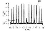
図3は、干渉計の種々の経路長差で測定された例示的なAラインプロファイルおよび/または点広がり関数220を示す。この測定に関して、本発明者らは、サンプルアームにおいてニュートラルデンシティ減衰器(73dB)および金で被覆したミラーを使用し、経路長は参照ミラーを移動することによって変化させた。最大SNRは、98dBの最大感受性に相当する25dBである。感受性の理論上の散弾雑音限界を計算すると109dBになり;本発明者らのシステムの感受性における11dBの不足は、SNR損失に寄与する多くの他の実験の詳細のうち、残余レーザー強度雑音、サンプルと参照光との間の不完全な偏光配置およびガウスウィンドウイングと考えられ、妥当なようである。例えば、例示的なSNR分析を促進するために、各々の例示的なプロットした曲線を、一定の深度で平均500を超える連続的な走査により取得し、雑音レベルを均一にするために簡単な数値の減算を行った。この図に示されるアスタリスク230として記されたゴーストアーティファクトは、レーザー光源におけるエタロン効果によって誘発された。 FIG. 3 shows exemplary A-line profiles and / or point spread functions 220 measured at various path length differences of the interferometer. For this measurement, we used a neutral density attenuator (73 dB) and a gold coated mirror in the sample arm and the path length was varied by moving the reference mirror. The maximum SNR is 25 dB, corresponding to a maximum sensitivity of 98 dB. The calculated theoretical shot noise limit of sensitivity is 109 dB; the lack of 11 dB in the sensitivity of our system is the residual laser intensity noise, sample, among many other experimental details that contribute to SNR loss. It seems to be reasonable to consider incomplete polarization arrangement and Gaussian windowing between the reference beam and the reference beam. For example, to facilitate an exemplary SNR analysis, each exemplary plotted curve is acquired with a continuous scan over a mean of 500 at a constant depth and a simple numerical value to make the noise level uniform. Subtraction was performed. The ghost artifact shown as
図3に示すように、レーザー出力の限界コヒーレンス長に起因して、経路長が2.4mmの深度まで増加するにつれて検出感度は92dBまで減少した。1040nmで広帯域光源を使用する従来の時間領域システムと比較した場合、本発明に従うシステムの例示的な実施形態は、より高い感受性、例えば、100倍速い画像獲得速度および6分の1のサンプルアーム電力を提供する。本発明に従うシステムの例示的な実施形態の高い感受性および深度範囲は有利に、800−900nmスペクトル範囲において広帯域光源を使用する例示的なSD−OCTシステムに匹敵する。眼内の液体による吸収のために、ヒトの網膜についての実際のSNRは、ミラーサンプルで測定された値より3−4dB低いようである。(図2(a)に示すように)使用した光源スペクトルおよびガウス窓関数に基づいて、理論上の距離分解能は空気中で約13μmであると測定され得;この測定された値は、深度とともに増大して14−16μmになり得る。高次項に起因する補間および分散補償における誤差は相違の原因となり得る。 As shown in FIG. 3, due to the critical coherence length of the laser output, the detection sensitivity decreased to 92 dB as the path length increased to a depth of 2.4 mm. When compared to a conventional time domain system using a broadband light source at 1040 nm, an exemplary embodiment of a system according to the present invention is more sensitive, eg, 100 times faster image acquisition speed and 1/6 sample arm power. I will provide a. The high sensitivity and depth range of the exemplary embodiment of the system according to the present invention is advantageously comparable to the exemplary SD-OCT system using a broadband light source in the 800-900 nm spectral range. Due to absorption by intraocular fluid, the actual SNR for the human retina appears to be 3-4 dB lower than the value measured with the mirror sample. Based on the light source spectrum used and the Gaussian window function (as shown in FIG. 2 (a)), the theoretical distance resolution can be measured to be about 13 μm in air; It can be increased to 14-16 μm. Errors in interpolation and dispersion compensation due to higher order terms can cause differences.
(インビボにおける網膜、視神経円板および脈絡膜の例示的なビデオ速度画像形成)
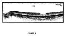
本発明に従うシステム、プロセスおよび構成の例示的な実施形態を用いて、例示的なOFDI画像形成を、2人の健康的なボランティア(A:36歳のアジア人男性、B:41歳のカフカス人男性)で行った。焦点サンプルビームが、網膜黄班部を5.2mm(垂直)と6mm(水平)の領域にわたって走査されて、例示的なOFDIシステムは10−20秒にわたって連続的に18,800のAラインを獲得した。図4は、10.6秒で18.8Hzのフレーム率でボランティアAから記録されたサンプルの中心窩および視神経円板の一連の画像250を示す。各画像フレームは、組織内の6.0mm(水平)および1.8mm(深度)にわたる各々のフレーム範囲で47dBを超える反射率範囲まで反転グレースケールテーブル写像を用いて1,000のAライン走査から構築した。例えば、5.2mmの垂直範囲で組織領域を画像化するために200のフレームを10.6秒で獲得した。網膜における解剖学的層は可視化されて、以前に公開されたOCT画像および組織学的所見との相関関係が十分に示された。(Example video velocity imaging of retina, optic disc and choroid in vivo)
Using an exemplary embodiment of the system, process and configuration according to the present invention, exemplary OFDI imaging is performed on two healthy volunteers (A: 36 year old Asian male, B: 41 year old Caucasian). Male). The focused sample beam is scanned across the retinal macular region over 5.2 mm (vertical) and 6 mm (horizontal) areas, and the exemplary OFDI system acquires 18,800 A lines continuously over 10-20 seconds. did. FIG. 4 shows a series of
図5Aは、本発明に従うシステム、プロセスおよび構成の例示的な実施形態を用いて3次元データセットから抽出された中心窩の拡大した例示的な画像を示す。図5Aの例示的なOFDI画像は、強膜との接触面近くまでの脈絡膜への深い侵入を示し、高密度に詰まった脈絡膜毛細血管および血管を可視化する。 FIG. 5A shows an enlarged exemplary image of a fovea extracted from a three-dimensional data set using an exemplary embodiment of the system, process and configuration according to the present invention. The exemplary OFDI image of FIG. 5A shows a deep penetration of the choroid near the scleral interface, visualizing densely packed choroidal capillaries and blood vessels.
本発明に従うシステム、プロセスおよび構成の例示的な実施形態の侵入を評価するために、2人のボランティアAおよびBが、ビデオ速度網膜画像化のために以前に開発されたOFDIシステムおよびSD−OCTシステムの両方を用いて3次元画像化され得る。SD−OCTシステムは、840nmの中心波長および50nmの3dBスペクトルバンド幅でスーパールミネセントダイオードを使用し、空気中で8−9nmの距離分解能を示した。29kHzのAライン速度および600μWのサンプルアーム電力レベルで、SD−OCTシステムは、空気中で2.2mmの最大範囲の深度にて82dBまで減少するゼロ遅延において98dBのピーク感受性を示した。 In order to evaluate the intrusion of exemplary embodiments of systems, processes and configurations according to the present invention, two volunteers A and B have previously developed OFDI systems and SD-OCTs for video rate retinal imaging. Three-dimensional imaging can be performed using both systems. The SD-OCT system used a superluminescent diode with a center wavelength of 840 nm and a 3 dB spectral bandwidth of 50 nm and showed a distance resolution of 8-9 nm in air. At 29 kHz A-line speed and 600 μW sample arm power level, the SD-OCT system showed a peak sensitivity of 98 dB at zero delay decreasing to 82 dB at a maximum range depth of 2.2 mm in air.
図5A−5Fは、2人のボランティアAおよびBの中心窩および視神経円盤付近のOFDIおよびSD−OCT画像の比較を並べて示す。例えば、図5Aおよび5Cは、ボランティアAからの中心窩および視神経頭におけるOFDI画像を示す。図5Bおよび5Dは、同様の組織部位における同じヒトからのSD−OCT画像を示す。図5Eおよび5Fは、ボランティアBから得たOFDIおよびSD−OCT画像をそれぞれ示す。例えば、示されるように、全てのデータセットではないにしても、大部分においてOFDI画像はSD−OCT画像より組織内のかなり深い侵入を示す。このような大きな侵入の深度は、高システム感受性および長い波長光源の両方から生じ得る。組織内の約11μmの比較的大きな距離分解能にもかかわらず、OFDIシステムは、(図5に示されるように)網膜、RNFL;網膜視神経線維束、IPL;内網状層、INL;内顆粒層、OPL;外網状層、ONL;外核層、IPRL;光受容体層の内節と外節との接触面、RPE;網膜色素上皮、C;脈絡膜毛細血管および脈絡膜{ない かりゅう そう}の解剖学的層状構造、を視覚化できる。 FIGS. 5A-5F show side by side comparisons of OFDI and SD-OCT images near the fovea and optic disc of two volunteers A and B. FIG. For example, FIGS. 5A and 5C show OFDI images in the fovea and optic nerve head from volunteer A. FIG. Figures 5B and 5D show SD-OCT images from the same human at similar tissue sites. Figures 5E and 5F show OFDI and SD-OCT images obtained from Volunteer B, respectively. For example, as shown, most if not all data sets, OFDI images show a much deeper penetration in the tissue than SD-OCT images. Such large penetration depth can arise from both high system sensitivity and long wavelength light sources. In spite of the relatively large distance resolution of about 11 μm in the tissue, the OFDI system (as shown in FIG. 5) is the retina, RNFL; retinal optic nerve fiber bundle, IPL; inner plexus layer, INL; OPL; outer plexiform layer, ONL; outer core layer, IPRL; contact surface between inner and outer photoreceptor layers, RPE; retinal pigment epithelium, C; choroidal capillaries and choroids The layered structure can be visualized.
これらの図に示されるように、SD−OCT画像におけるより高い距離分解能は、網膜層の間のより良いコントラストを提供するが、OFDI画像はSD−OCT画像と比較して脈絡膜へのかなり深い侵入を示す。840nmに比して1050nmにおけるRPEの低い吸収および散乱は、同等の感受性を有するSD−OCTシステムよりOFDIシステムの明らかに優れた侵入の原因となり得る。
As shown in these figures, higher distance resolution in SD-OCT images provides better contrast between retinal layers, but OFDI images have a much deeper penetration into the choroid compared to SD-OCT images. Indicates. The low absorption andscattering of RPE at 1050 nmcompared to 840 nm can cause an apparently better penetration of the OFDI system than the SD-OCT system with comparable sensitivity.
(OFDI技術/システムを用いる網膜/脈絡膜血管の視覚化)
眼の後部の3次元トモグラフィーデータを用いて、全深度軸に沿ったピクセル値が、1つの2次元基底部型反射率画像を生成するために統合され得る。図6Aは、従来の全範囲統合法を用いて得た2次元反射率画像(5.3×5.2mm2)である前記画像の図4に示される全OFDI画像シーケンスから生成された1つの例示的な統合された反射率画像を示す。前記例示的な画像は、例示的な視神経頭、中心窩、網膜血管および深い脈絡膜血管の外形を示す。しかしながら、深度情報は示されていない。従来の方法によって生成されたこの画像の欠陥を扱うために、本発明のシステム、プロセスおよび構成の例示的な実施形態を用いることによって、選択的領域のみを統合することは可能である。
(Visualization of retina / choroidal vessels using OFDI technology / system)
Using the 3D tomographic data of the posterior part of the eye, pixel values along the full depth axis can be integrated to generateone 2D basal reflectance image. 6A isthe one generated from the total OFDI image sequence shown in Figure 4ofthe prior art ofthe image is atwo-dimensional reflectance image obtained with the full scope integration method (5.3 × 5.2
例えば、本発明の1つの例示的な実施形態に従って、最大コントラストで網膜血管を可視化するために、図6Bに示されるようにIPRLとRPE260、270との間の範囲の反射率を統合することが可能である。この図は、基底部型反射率画像を生成するための軸方向横断統合技術の例示的な実施形態の図を示す。上記の網膜血管によって作製された信号の影または損失は、非常にはっきり見ることができる。血管を含む全ての網膜を統合することによって、しばしば、脈管構造においてより低いコントラストを生じる。なぜなら、網膜血管は強い散乱によって大きな信号を生成するからである。自動画像処理は、都合良く、IPRL層260およびRPE層270の自動化区分を可能にする。
For example, according to one exemplary embodiment of the present invention, in order to visualize the retinal vascularin maximum contrast, the integration of reflectivity ranging between IPRL and RPE260,270 as shown in FIG. 6B Is possible. This figure shows a diagram of an exemplary embodiment of an axial transverse integration technique for generating a base-type reflectance image. The shadow or loss of the signal produced by the retinal blood vessels can be seen very clearly. By integrating all retinas, including blood vessels, often results in lower contrast in the vasculature. This is because retinal blood vessels generate large signals due to strongscattering . Automatic image processing advantageously allows for automated segmentation of
図6Cは、網膜血管の血管系(3.8×5.2mm2)の例示的な反射率画像(影)を示す。RPEより下の薄い統合領域を用いて、図6Dに示されるように脈絡膜の上部から得た十分に小さな血管および色素細胞を含む脈絡膜毛細血管層の基底部型反射率画像を得ることもまた可能である。完全な脈絡膜領域の画像を得るために、図6Bの参照280および290によって示される統合範囲を利用することが可能である。脈絡膜血管は、図6Eの例示的な生成された反射率画像に示され、これは、脈絡膜血管を明らかにする脈絡膜の中心からの統合された例示的な反射率画像である。同様の性質を有する反射率画像は、ボランティアBから得られ得る。FIG. 6C shows an exemplary reflectance image (shadow) of the retinal vasculature (3.8 × 5.2 mm2 ). It is also possible to obtain a basal-type reflectance image of the choroidal capillary layer containing sufficiently small blood vessels and pigment cells obtained from the top of the choroid, as shown in FIG. 6D, using a thin integrated area below the RPE It is. In order to obtain an image of the complete choroidal region, it is possible to utilize the integrated range indicated by
(本発明の例示的な実施形態の例示的な実施)
実験結果は、1050nmで例示的なOFDI技術を用いて生成した画像が、高分解能および高コントラストでヒトの網膜および脈絡膜の広範囲の画像形成を提供することができることを示す。しかしながら、本発明の例示的な実施形態に従うOFDIシステムの例示的な実施形態は、従来の時間領域OCTシステムの使用より一桁高い画像獲得速度を提供することができ、840nmでのSD−OCTシステムと比べて向上したコントラストの脈絡膜画像に役立つ。向上した侵入により、脈絡膜毛細血管および血管ネットワークの深度断面反射率画像を得ることが可能となる。眼低カメラまたは走査レーザー検眼鏡は、従来通り血管系を見るために使用されている。しかしながら、このような方法は、かなり低いレベルの色素形成を有する患者を除いて脈絡膜へと接近するために蛍光またはインドシアニングリーン血管造影を必要とし得る。(Exemplary Implementation of Exemplary Embodiments of the Invention)
Experimental results show that images generated using the exemplary OFDI technique at 1050 nm can provide extensive imaging of the human retina and choroid with high resolution and high contrast. However, an exemplary embodiment of an OFDI system according to an exemplary embodiment of the present invention can provide an image acquisition rate that is an order of magnitude higher than the use of a conventional time domain OCT system, and an SD-OCT system at 840 nm. Useful for improved contrast choroidal images. With improved penetration, it is possible to obtain depth cross-sectional reflectance images of choroidal capillaries and vascular networks. Low eye cameras or scanning laser ophthalmoscopes are conventionally used to view the vasculature. However, such methods may require fluorescence or indocyanine green angiography to gain access to the choroid except for patients with fairly low levels of pigmentation.
本発明に従う例示的なOFDIシステムは、例えば市販のSOAおよび特注の腔内走査フィルタを用いて生成された波長掃引レーザーを備える。そのようなレーザーの出力、チューニング速度および範囲は、組織内に約98dBの感受性、19kHzのAライン速度および10μmの分解能を生じ得る。飽和出力およびSOAの利得を増加させること、および拡大空洞損失を減少させることによって、感受性および分解能(チューニング範囲)をさらに改良することができる。例えば、本発明に従うシステムの例示的な実施形態の電力暴露レベルは550μWのみであり得、一方、1050nmでの最大ANSI限界は1.9mWであるようである。 An exemplary OFDI system according to the present invention comprises a wavelength swept laser generated using, for example, a commercially available SOA and a custom-made intracavity scanning filter. The power, tuning speed and range of such a laser can produce a sensitivity of about 98 dB in the tissue, an A-line speed of 19 kHz and a resolution of 10 μm. Sensitivity and resolution (tuning range) can be further improved by increasing the saturation power and SOA gain and reducing the extended cavity loss. For example, the power exposure level of an exemplary embodiment of a system according to the present invention may be only 550 μW, while the maximum ANSI limit at 1050 nm appears to be 1.9 mW.
(掃引レーザー光源の例示的な実施形態)
図7(a)は、本発明に従う、例えば815−870nmのスペクトル範囲における掃引レーザー光源構成の別の例示的な実施形態を示す。掃引レーザー光源構成部は、自由空間アイソレータ310を有する光ファイバの単方向リング空洞300を備え得る。利得媒質320は、市販の利用可能な半導体光増幅器(例えばSOA−372−850−SM、Superlum Diodes Ltd.)であり得る。備えられ得る腔内スペクトルフィルタ330は、回折格子(例えば830溝/mm)332、4f構造において2つの色消レンズ334、336、および72面多面鏡340(Lincoln lasers,Inc.)を含み得る。多面鏡は1秒につき約600回転で回転し得、43.2kHzの繰り返し率で短波長から長波長まで一方向の掃引を生成することができる。(Exemplary Embodiment of Swept Laser Light Source)
FIG. 7 (a) shows another exemplary embodiment of a swept laser source configuration, eg, in the spectral range of 815-870 nm, according to the present invention. The swept laser source component may comprise an optical fiber
空洞内の自由空間平行ビームは約1mmFWHM(半値全幅)のサイズを有し得る。格子法線に対するビーム入射角は67degであり得る。テレスコープ内の2つのレンズ334、336の焦点距離は、それぞれ75(f1)mmおよび40(f2)mmであり得る。55nmの自由スペクトル領域および0.17nmのFWHMフィルタバンド幅を予測することが可能である。光ファイバカプラ350の70%ポートを介してレーザー出力は得られ得る。2つの偏光制御装置360、362は出力およびチューニング範囲を最大化するために使用され得る。The free space parallel beam in the cavity may have a size of about 1 mm FWHM (full width at half maximum). The beam incident angle relative to the grating normal can be 67 deg. The focal lengths of the two
例えば、約43.2kHzの掃引速度にてレーザー出力のスペクトルおよび時間特性を測定することは可能である。SOAは、約110mAの注入電流で駆動され得る。図7(b)は、0.1nmの分解能バンド幅でピークホールドモードにおいて例示的な光スペクトル分析器で測定された例示的な出力スペクトル380、385を示す。全チューニング範囲は55nmであり、38nmのFWHMバンド幅で815nm〜870nmである。出力の安定性は、約43.2kHzの掃引速度および7mWの平均出力という条件で、図7(c)に示されるようにシングルショットオシロスコープトレース390において提供される。チューニングサイクルにわたるピーク出力の変化は1%未満であり得る。瞬間レーザー発光は、複数の縦モードを含み得る。 For example, it is possible to measure the spectral and temporal characteristics of the laser output at a sweep rate of about 43.2 kHz. The SOA can be driven with an injection current of about 110 mA. FIG. 7 (b) shows
(図3(b)に示されるような)コヒーレンス長の例示的な測定は、FWHMライン幅がフィルタバンド幅に相当する約0.17nmであり得ることを示し得る。レーザー出力の強度雑音特性は、電気スペクトル分析器(例えばModel、Agilent)および低利得シリコン検出器を用いることによってさらに特徴付けられる。測定された相対強度雑音は、約2MHzから10MHzの周波数範囲における周波数で減少する約−125dB/Hzから−135dB/Hzの範囲であり得る。縦モードビーティングに起因する雑音ピークは91MHzで現れ得る。時間平均出力は約6.9mWであり得る。 An exemplary measurement of coherence length (as shown in FIG. 3 (b)) may indicate that the FWHM line width may be about 0.17 nm, corresponding to the filter bandwidth. The intensity noise characteristic of the laser output is further characterized by using an electrical spectrum analyzer (eg, Model, Agilent) and a low gain silicon detector. The measured relative intensity noise can range from about -125 dB / Hz to -135 dB / Hz, decreasing at frequencies in the frequency range of about 2 MHz to 10 MHz. A noise peak due to longitudinal mode beating can appear at 91 MHz. The time average power can be about 6.9 mW.
例えば約70%のレーザー光源構成部の例示的な実施形態の大きな出力連結比は、SOAでのピーク出力が約20mW(例えばSOAの規定された光損傷閾値)を超えないことを確実にし得る。この状態が満たされない場合、突然の壊滅的またはゆっくりとした処理損傷がSOAチップの出力面で起こり得る。例えば新しいチップ設計によって800nmSOAチップの光損傷閾値を増加させることは、チューニング速度および長時間の信頼性を向上させ得る。出力は、全平均出力の約8%(約0.56mW)を占め得る広域幅増幅自然放出を含み得る。 For example, a large power coupling ratio of an exemplary embodiment of a laser source component of about 70% may ensure that the peak power at the SOA does not exceed about 20 mW (eg, the SOA's prescribed optical damage threshold). If this condition is not met, sudden catastrophic or slow processing damage can occur at the output surface of the SOA chip. For example, increasing the optical damage threshold of an 800 nm SOA chip with a new chip design may improve tuning speed and long-term reliability. The output can include broad-band amplified spontaneous emission that can account for about 8% (about 0.56 mW) of the total average power.
(例示的な画像形成システム)
本発明に従うOFDIシステムの例示的な実施形態は、例示的な波長掃引レーザー構成部を用いて提供することができる。例示的なシステムの構造は、図1(b)に示されるシステムと同様であり得る。レーザー出力は、30/70カプラによって干渉計内の2つの経路に分割され得る。1つの経路(例えば「サンプルアーム」と呼ばれる30%ポート)において、2軸検流計走査(例えばModel、Cambridge Technologies)を介して生物学的サンプルを照射することができる。もう1つの経路「参照アーム」は一般に参照ビームを与える。後方散乱によってサンプルから戻ってくる信号ビームは、参照ビーム(例えば50/50カプラ)と合成され、それによって干渉を生成する。(Exemplary image forming system)
An exemplary embodiment of an OFDI system according to the present invention can be provided using an exemplary wavelength swept laser component. The structure of an exemplary system can be similar to the system shown in FIG. The laser output can be split into two paths in the interferometer by a 30/70 coupler. In one path (eg, a 30% port referred to as a “sample arm”), a biological sample can be illuminated via a biaxial galvanometer scan (eg, Model, Cambridge Technologies). Another path “reference arm” generally provides a reference beam. The signal beam returning from the sample by backscattering is combined with a reference beam (eg, a 50/50 coupler), thereby generating interference.
干渉信号は、2重平衡シリコンレシーバ(例えばDC−80MHz、1807−FS、New Focus)で検出され得る。レシーバ出力はローパスフィルター(35MHz)をかけられ、14ビットデータ取得ボード(例えばDAQ、NI−5122、National Instruments)を用いて100MS/sのサンプリング速度でデジタル化される。トリガーをDAQボードに与えるために参照ビームのごく一部(10%)はタップされ、格子フィルタを通して検出され得る。各波長掃引またはAライン走査の間に、多く(例えば2048サンプル)が獲得され得る。抽出されたデータは、オンボードメモリまたは別の記憶装置に初期に保存され得る。 The interference signal can be detected with a double balanced silicon receiver (eg, DC-80 MHz, 1807-FS, New Focus). The receiver output is low pass filtered (35 MHz) and digitized at a sampling rate of 100 MS / s using a 14 bit data acquisition board (eg, DAQ, NI-5122, National Instruments). A small portion (10%) of the reference beam can be tapped and detected through a grating filter to provide a trigger to the DAQ board. Many (eg, 2048 samples) can be acquired during each wavelength sweep or A-line scan. The extracted data can be initially stored in on-board memory or another storage device.
所望の数のAライン走査を収集する際に、データセットはホストパーソナルコンピューター、オンライン処理のためのメモリ/保存構成部のいずれか、および/またはディスプレイもしくは後処理のためのハードディスクに転送され得る。シングルフレームのみが一定の時間に獲得される場合、例示的なシステムは、約5Hzのフレームリフレッシュ速度でリアルタイムにおいて画像フレームを処理および表示可能することができる。より大きなデータセットに関して、例示的な256MBオンボードメモリは、連続して約1.3秒間、65,536までのAライン走査の獲得を与える。これは約128画像フレームに相当し、各々512のAラインからなる。データ後処理技術としては、参照物減算、アポダイゼーション、線形k−空間内への補間、およびフーリエ変換前の分散補償が挙げられ得る。 In collecting the desired number of A-line scans, the data set can be transferred to either a host personal computer, a memory / storage component for online processing, and / or a hard disk for display or post-processing. If only a single frame is acquired at a certain time, the exemplary system can process and display image frames in real time with a frame refresh rate of about 5 Hz. For larger data sets, the exemplary 256 MB onboard memory provides acquisition of A-line scans up to 65,536 for approximately 1.3 seconds in a row. This corresponds to about 128 image frames, each consisting of 512 A lines. Data post-processing techniques can include reference subtraction, apodization, interpolation into linear k-space, and dispersion compensation prior to Fourier transform.
本発明に従うシステム、プロセスおよび構成の例示的な実施形態を特徴付け、最適化するために、サンプル(−50dB反射率)として半透明ミラーを用いることによって軸点広がり関数(すなわちAライン)を使用することが可能である。図8(a)は、参照屈折力の関数として測定された例示的なシステムの感受性のグラフ400を示す。参照屈折力は、参照アームにおいて可変ニュートラルデンシティ(ND)フィルタを用いることによって変化することができる。例えば、この測定を通して、サンプルと参照アームとの間の経路長差は約0.6mmであり得、減衰されたサンプルミラーから戻ってくる屈折力は、50/50カプラの各ポートにおいて3.3nWであり得る。感受性の値は、サンプル減衰(例えば約50dB)を測定された信号対雑音比(SNR)に加えることによって測定され得る。参照電力は50/50カプラのポートの1つにおいて測定され得、各光ダイオードでの時間平均参照電力に相当する。約30μWと200μWとの間の参照電力、約96dBの最大感受性が取得され得る。 Using an axial spread function (ie, A-line) by using a translucent mirror as a sample (−50 dB reflectivity) to characterize and optimize exemplary embodiments of systems, processes and configurations according to the present invention Is possible. FIG. 8 (a) shows a
デシベルの単位における感受性は以下のように表され得る。
SdB=S0−10log10(1+a/Pr+Pr/b)−Δ
ここで、S0は散弾雑音限界感受性を示し、Prは参照電力レベルであり、熱雑音および強度雑音において参照電力レベルに相当するaおよびbは、それぞれ、大きさにおいて散弾雑音のレベルと等しくなり、Δは、感受性の損失に寄与する他の要因と関連する調整パラメーターであり得る。増幅自然放出を考慮に入れると、S0は約107dBであり得る。例えば、検出雑音レベル(例えば3.3pA/√Hz)および変換効率(例えば1A/W)からa=17μWである。レーザー(例えば−130dB/Hz)の相対強度雑音および平衡レシーバの抑制効率の18dB共通雑音に基づいて、b=280μWである。例えば、図8(b)の実験データ410に最も適合するのはΔ=8dBを用いて取得され得る。図8(b)は、深度の関数として測定された感受性420のグラフを示す。この例示的な値は、フラット参照スペクトル、サンプル光と参照光との間の偏光ミスマッチ、およびデータ処理におけるアポダイゼーション工程を想定する単純化したモデルに大部分起因し得、各々はいくらかのdBによる感受性の損失に起因するようである。Sensitivity in units of decibels can be expressed as:
SdB = S0 -10 log10 (1 + a / Pr + Pr / b) −Δ
Here, S0 indicates shot noise limit sensitivity,Pr is a reference power level, and a and b corresponding to the reference power level in thermal noise and intensity noise are equal to the level of shot noise in magnitude, respectively. And Δ can be an adjustment parameter associated with other factors that contribute to loss of sensitivity. Taking into account amplified spontaneous emission, S0 can be about 107 dB. For example, a = 17 μW from the detected noise level (for example, 3.3 pA / √Hz) and the conversion efficiency (for example, 1 A / W). Based on the relative intensity noise of the laser (eg -130 dB / Hz) and the 18 dB common noise of the balanced receiver suppression efficiency, b = 280 μW. For example, the best fit with the
レーザー光源の限界コヒーレンス長に起因して、感受性は干渉遅延増加とともに減少し得る。参照アーム内の遅延を変化させることによってサンプルミラーの種々の深度部位において軸点広がり関数を測定することは可能であるが、図8(b)のグラフに示されるように参照電力を光ダイオードあたり約100μWで維持する。例えば、各々の軸プロファイルは、サンプルアームを遮断することによって取得される雑音レベルを測定することによって調整され得、その後50dBレベルに雑音レベルを合わせる。この方法において、雑音レベルの最も適切な周波数または深度依存(約2dB)は減少され得るか、または除去され得る。従って、感受性は約1.9mmの深度において約6dBまで下がり得る。ガウスフィット(点線)より、瞬時レーザーライン幅は約0.17nmであり得る。軸プロファイルのFWHMまたは空気中の軸分解能は、0からBmmまでの深度において約8μmであり得る。これは、組織画像形成
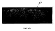
例として、高速高分解生物学的画像形成についての本発明に従うシステム、プロセスおよび構成の例示的な実施形態の機能を確認および示すために、アフリカツメガエルのオタマジャクシの画像が、インビボにおいてサンプルビーム(Bモード走査)を走査することによって得られ得る。サンプルビームは、約250μmの共焦点パラメーターおよび空気中の焦点(n=1)において約7μmのFWHMビームサイズを有し得る。サンプル上の屈折力は約2.4mWであり得る。画像形成処理の間、オタマジャクシ(ステージ46)は、約0.02%の3−アミノ安息香酸エチルエステル(MS−222)の滴下によりウォーターバス中で麻酔下に存在し得る。 As an example, to confirm and demonstrate the functionality of an exemplary embodiment of the system, process and configuration according to the present invention for high-speed, high-resolution biological imaging, images of Xenopus tadpoles were sampled in vivo (B Mode scanning). The sample beam may have a confocal parameter of about 250 μm and a FWHM beam size of about 7 μm at a focus in air (n = 1). The refractive power on the sample can be about 2.4 mW. During the imaging process, tadpoles (stage 46) may be present under anesthesia in a water bath by instillation of about 0.02% 3-aminobenzoic acid ethyl ester (MS-222).
図9は、ビームが1次元で心臓の心室の上に繰り返し走査されて得た一連の画像450を示す。画像シーケンスは、1.2秒間に84.4Hz(1フレームにつき512Aライン)のフレーム率で獲得されたが、1秒につき24フレームの減少率で表示される。オリジナル(500×1024ピクセル)から切り取った各フレームは、400×200ピクセルを有し、1.1mm(深度、n=1.35)と3.3mm(水平方向)の寸法に及ぶ。小柱を含む心室の動きが見られ得る。高空間分解能および高時間分解能で鼓動している心臓を画像化する能力は、インビボにおける正常および異常な心臓発達を調べるのに有用であり得る。800nm領域で開発されたICGおよび金ナノ粒子のような造影剤と組み合わせて、本発明に従うOFDIシステム、プロセスおよび構成の例示的な実施形態は、高速機能または分子画像形成を可能にする。 FIG. 9 shows a series of
(例示的なレーザー電流調節)
OFDI画像形成についての例示的な好ましい光源構成は、一般に、均一の出力スペクトルを有する。そのような所望のスペクトルプロファイルを得るために、利得媒質の利得もしくは損失、またはレーザー空洞のフィルタ内部もしくは外部を調節することができる。フィルタは広帯域可変減衰器であり得、その送信はレーザーチューニングと同調して制御され得る。例示的なフィルタは、所望の透過スペクトルを有する受動的スペクトルフィルタであり得る。利得媒質は好ましくは半導体光増幅器であり得、その利得は注入電流をフィルタチューニングと同調して増幅器に調節することによって変化され得る。図10(a)および10(b)は、それぞれ、本発明に従う調節方法の例示的な実施形態を使用する例示的な出力チューニングトレース480、使用ない例示的な出力チューニングトレース490のグラフを示す。この例示的な方法はまた、半導体利得チップの所定の光損傷閾値についての出力電力およびチューニング範囲を最大化または少なくとも増加させるために効果的であり得る。(Example laser current adjustment)
Exemplary preferred light source configurations for OFDI imaging generally have a uniform output spectrum. In order to obtain such a desired spectral profile, the gain medium loss or loss, or the filter inside or outside the laser cavity can be adjusted. The filter can be a broadband variable attenuator and its transmission can be controlled in tune with the laser tuning. An exemplary filter may be a passive spectral filter having a desired transmission spectrum. The gain medium may preferably be a semiconductor optical amplifier, the gain of which may be varied by adjusting the injection current to the amplifier in tune with the filter tuning. FIGS. 10 (a) and 10 (b) show graphs of an exemplary
(例示的な流量測定)
眼の網膜および脈絡膜において血流を検出および定量化する能力は、加齢性黄班変性の診断のようないくらかの臨床応用において効果を有し得る。OFDI信号の位相から流量情報を抽出するいくらかの方法は、当該分野において公知である。しかしながら、これらの例示的な従来の方法は、サンプリングの間にわたって、2つの連続的なAライン走査の間に有意なビームのオーバーラップを必要とし、それによって、位相確度と画像獲得速度との間に望んでいない障害を引き起こす。本発明に従うシステム、プロセスおよび構成の例示的な実施形態を用いて2つのAライン走査の位相値を比較する代わりに、単一のAライン内の異なる時点または波長に対応する複数の位相値を抽出し、その値と参照位相値とを比較することができる。この例示的な手段は、単一のAライン走査の間の多数の時点での流速の測定を提供し、より速いビーム走査および画像獲得速度を可能にする。そのような手段は、多くの用途において受け入れられるような低下した位相または速度測定精度において使用され得る。
(Example flow measurement)
The ability to detect and quantify blood flow in the retina and choroid of the eye may have an effect in some clinical applications such as the diagnosis of age-related macular degeneration. Some methods of extracting flow information from the phase of the OFDI signal are known in the art. However, these exemplary conventional methods require significant beam overlap between two successive A-line scans during sampling, thereby reducing phase accuracy and image acquisition speed. Cause unwanted disabilities. Instead of comparing the phase values of two A-line scans using exemplary embodiments of systems, processes and configurations according to the present invention, multiple phase values corresponding to different time points or wavelengths within a single A-line are obtained. It is possible to extract and compare the value with the reference phase value. This exemplary means provides flow rate measurementsat multiple time points duringa single A-line scan, allowing for faster beam scanning and image acquisition rates. Such means can be used with reduced phase or velocity measurement accuracy as would be acceptable in many applications.
図11は、各波長走査の間に得た全データセットから位相および速度情報を抽出するための従来の方法のフローチャートを示す。図10に示されるように、Aライン走査のk番目から(k+1)番目が提供される。工程510において、このような走査の各々からのDFTが受信されて、それぞれ、式
図12は、干渉縞データの半分をプロセシングすることによって位相および流量情報を得るために使用され得る本発明に従うプロセスの例示的な実施形態のフローチャートを示す。例えば、図11に示される従来の方法と同様に、Aライン走査のk番目から(k+1)番目が提供される。次いで、工程560において、このような走査の各々からのDFTが受信され、それぞれ以下の式において利用される。
図13(a)および13(b)は、健康なボランティアから得た網膜の例示的な画像を示す。例えば、図13(a)は、本発明に従うシステム、プロセスおよび構成の例示的な実施形態を用いて連続的に獲得した多数のフレームからの単一の例示的な画像を示す。画像フレームは約1000軸のラインからなり、例示的な画像は患者の中心窩および視神経円板を示す。図13(b)は、各深度プロファイルにおいて強度を統合することによって領域を覆う複数の断面像から生成された例示的な統合された基底部画像を示し、本発明に従うシステム、プロセスおよび構成の例示的な実施形態を用いた基底部画像における一点を表す。 Figures 13 (a) and 13 (b) show exemplary images of the retina obtained from healthy volunteers. For example, FIG. 13 (a) shows a single exemplary image from multiple frames acquired sequentially using an exemplary embodiment of the system, process and configuration in accordance with the present invention. The image frame consists of approximately 1000 axis lines, and the exemplary image shows the patient's fovea and optic disc. FIG. 13 (b) shows an exemplary integrated base image generated from multiple cross-sectional images covering an area by integrating intensity in each depth profile, and is an illustration of the system, process and configuration according to the present invention. 1 represents a point in a base image using an exemplary embodiment.
これらの図に示されるように、網膜OFDI画像形成は、41歳のカフカス人男性被験者でインビボにおいて800−900nmで実施される。本発明に従うOFDIシステム、プロセスおよび構成の例示的な実施形態は、焦点を合わせたサンプルビームを、網膜内の黄班領域および視神経頭領域に走査すると、1〜2秒間にわたって連続的に23kAラインを獲得した。各画像フレームは、反射率領域に対して反対のグレースケールテーブルマッピングを有する1,000のAライン走査から構成された。網膜内の解剖学的層は、はっきりと視覚化され、以前に公開されたOCT画像および組織学的所見と十分に相互に関連がある。 As shown in these figures, retinal OFDI imaging is performed in vivo at 800-900 nm in a 41 year old Caucasian male subject. An exemplary embodiment of an OFDI system, process and configuration in accordance with the invention scans a focused sample beam over the macula and optic nerve head regions in the retina and continuously produces a 23 kA line for 1-2 seconds. Won. Each image frame consisted of 1,000 A-line scans with opposite grayscale table mapping for the reflectance area. Anatomical layers in the retina are clearly visualized and correlate well with previously published OCT images and histological findings.
上述は本発明の原理を単に示しただけである。記載した実施形態に対して種々の改変および代替は、本明細書中に教示されている観点から当業者に明らかである。実際に、本発明の例示的な実施形態に従う構成、システムおよび方法は、例えば、2004年9月8日に出願された国際特許出願番号PCT/US2004/029148明細書、2005年11月2日に出願された米国特許出願第11/266,779号明細書および2004年7月9日に出願された米国特許出願第10/501,276号明細書(これらの開示はその全体が本明細書中に参照として援用される)に記載されている任意のOCTシステム、OFDIシステム、SD−OCTシステムまたは他の画像形成システムを用いて使用され得る。従って当業者が、本明細書中に明確に示されるかまたは記載されない限り、本発明の原理を具現化し、それによって本発明の趣旨および範囲内に入る多数のシステム、構成および方法を考案することは理解される。さらに、従来技術の知識が本明細書中に参照として明確に援用されない限り、その全体は本明細書中に明確に援用される。本明細書中に参照した全ての刊行物は、その全体が参照として本明細書中に援用される。 The foregoing merely illustrates the principles of the invention. Various modifications and alternatives to the described embodiments will be apparent to those skilled in the art from the viewpoints taught herein. Indeed, configurations, systems and methods according to exemplary embodiments of the present invention are described, for example, in International Patent Application No. PCT / US2004 / 029148, filed Nov. 2, 2005, filed Sep. 8, 2004. US patent application Ser. No. 11 / 266,779 and US application Ser. No. 10 / 501,276 filed Jul. 9, 2004, the disclosures of which are hereby incorporated by reference in their entirety. Can be used with any OCT system, OFDI system, SD-OCT system or other imaging system described in US Pat. Accordingly, those skilled in the art will devise numerous systems, configurations and methods that embody the principles of the invention and thereby fall within the spirit and scope of the invention, unless expressly stated or described herein. Is understood. Further, the whole is expressly incorporated herein in its entirety unless prior art knowledge is expressly incorporated herein by reference. All publications referred to herein are hereby incorporated by reference in their entirety.
Claims (16)
Translated fromJapanese少なくとも1つの第1の電磁放射と関連付けられた少なくとも1つの第3の電磁放射と、前記少なくとも1つの第2の電磁放射と関連付けられた少なくとも1つの第4の電磁放射との間の干渉信号を検出できる少なくとも1つの第2の構成部と、を備える装置であって、
前記少なくとも1つの第2の構成部は、前記波長の1つの全掃引より少ない範囲にわたって前記干渉信号の少なくとも1つの周波数成分の少なくとも1つの位相と関連付けられた少なくとも1つの信号を取得するように、そして前記少なくとも1つの位相と少なくとも1つの特定の情報とを比較するように構成された、装置。At least one first component for providing radiation comprising at least one first electromagnetic radiation directed at the sample and at least one second electromagnetic radiation directed at the reference, said at least one At least one first component, wherein the wavelength of the radiation provided by one first component varies with time;
The thirdelectromagnetic radiation of at least one associated with at least one firstelectromagnetic radiation, an interference signal between the at least one fourth ofelectromagnetic radiation associated with at least one secondelectromagnetic radiation An apparatus comprising at least one second component that can be detected,
The at least one second component obtains at least one signal associated with at least one phase of at least one frequency component of the interference signal over a range less thanone full sweep of the wavelengths; Andan apparatusconfigured to compare the at least one phase with at least one particular information.
前記少なくとも1つの第2の構成部はさらに、前記少なくとも1つの第5の電磁放射と前記少なくとも1つの第4の電磁放射との間のさらなる干渉信号を検出でき、
前記少なくとも1つの第2の構成部はさらに、前記波長の1つの全掃引より少ない範囲にわたって前記さらなる干渉信号の少なくとも1つの第1の周波数成分のさらなる位相と関連付けられた少なくとも1つの参照信号を得ることができる、請求項1に記載の装置。At least one fifth configured to receive at least one of the first or second electromagnetic radiation and associated with at least one of the first electromagnetic radiation or the second electromagnetic radiation. Comprising at least one third component for supplying the electromagnetic radiation of
The at least one second component can further detect a further interference signal between the at least one fifthelectromagnetic radiation and the at least one fourthelectromagnetic radiation;
The at least one second component further obtains at least one reference signal associated with a further phase of the at least one first frequency component of the further interference signal over a range less thanone full sweep of the wavelength. The apparatus of claim 1, wherein the apparatus is capable of.
前記少なくとも1つの第1の電磁放射と関連付けられた少なくとも1つの第3の電磁放射と、前記少なくとも1つの第2の電磁放射と関連付けられた少なくとも1つの第4の電磁放射との間の干渉信号を検出する工程と、
前記波長の1つの全掃引より少ない範囲にわたって前記干渉信号の少なくとも1つの周波数成分の少なくとも1つの位相と関連付けられた少なくとも1つの信号を得る工程であって、該工程は前記少なくとも1つの位相と少なくとも1つの特定の情報とを比較する工程と、を包含する処理方法。Producing radiation supplied with radiation comprising at least one first electromagnetic radiation directed at the sample and at least one second electromagnetic radiation directed at the reference, wherein the process comprises at least 1 The wavelength of the radiation supplied by one of the first components changes with time,
Wherein the at least one thirdelectromagnetic radiation of at least one associated with the firstelectromagnetic radiation, the at least one second interference signal between at least one fourth of theelectromagnetic radiation associated with theelectromagnetic radiation Detecting
Obtaining at least one signal associated with at least one phase of at least one frequency component of the interference signal over a range less thanone full sweep of the wavelength, the step comprising at least one phase and at least one phase Comparing with one particular piece of information.
サンプルに向けられた少なくとも1つの第1の電磁放射、および参照物に向けられた少なくとも1つの第2の電磁放射を含む放射が供給される放射を生じさせる第1の命令セットであって、少なくとも1つの第1の構成部によって供給された前記放射の波長は時間とともに変化し、
前記少なくとも1つの第1の電磁放射と関連付けられた少なくとも1つの第3の電磁放射と、前記少なくとも1つの第2の電磁放射と関連付けられた少なくとも1つの第4の電磁放射との間の干渉信号の検出を誘導する第2の命令セットと、
前記波長の1つの全掃引より少ない範囲にわたって前記干渉信号の少なくとも1つの周波数成分の少なくとも1つの位相と関連付けられた少なくとも1つの信号を得て、前記少なくとも1つの位相と少なくとも1つの特定の情報とを比較する、第3の命令セットと、を含むプログラム。A program executed by a processing device, the processing device comprising:
A first instruction set for generating radiation that is provided with radiation comprising at least one first electromagnetic radiation directed at the sample and at least one second electromagnetic radiation directed at the reference, The wavelength of the radiation supplied by one first component varies with time,
Wherein the at least one thirdelectromagnetic radiation of at least one associated with the firstelectromagnetic radiation, the at least one second interference signal between at least one fourth of theelectromagnetic radiation associated with theelectromagnetic radiation A second instruction set that guides the detection of
Obtaining at least one signal associated with at least one phase of at least one frequency component of the interfering signal over a range less thanone full sweep of the wavelength, the at least one phase and at least one specific information; And a third instruction set.
Applications Claiming Priority (2)
| Application Number | Priority Date | Filing Date | Title |
|---|---|---|---|
| US79951106P | 2006-05-10 | 2006-05-10 | |
| US60/799,511 | 2006-05-10 |
Related Parent Applications (1)
| Application Number | Title | Priority Date | Filing Date |
|---|---|---|---|
| JP2009510092ADivisionJP2009536740A (en) | 2006-05-10 | 2007-05-04 | Process, configuration and system for providing frequency domain imaging of samples |
Publications (2)
| Publication Number | Publication Date |
|---|---|
| JP2013011625A JP2013011625A (en) | 2013-01-17 |
| JP5587956B2true JP5587956B2 (en) | 2014-09-10 |
Family
ID=38653576
Family Applications (3)
| Application Number | Title | Priority Date | Filing Date |
|---|---|---|---|
| JP2009510092APendingJP2009536740A (en) | 2006-05-10 | 2007-05-04 | Process, configuration and system for providing frequency domain imaging of samples |
| JP2012225358AActiveJP5587955B2 (en) | 2006-05-10 | 2012-10-10 | Process, configuration and system for providing frequency domain imaging of samples |
| JP2012225360AActiveJP5587956B2 (en) | 2006-05-10 | 2012-10-10 | Process, configuration and system for providing frequency domain imaging of samples |
Family Applications Before (2)
| Application Number | Title | Priority Date | Filing Date |
|---|---|---|---|
| JP2009510092APendingJP2009536740A (en) | 2006-05-10 | 2007-05-04 | Process, configuration and system for providing frequency domain imaging of samples |
| JP2012225358AActiveJP5587955B2 (en) | 2006-05-10 | 2012-10-10 | Process, configuration and system for providing frequency domain imaging of samples |
Country Status (4)
| Country | Link |
|---|---|
| US (3) | US8175685B2 (en) |
| EP (3) | EP3150110B1 (en) |
| JP (3) | JP2009536740A (en) |
| WO (1) | WO2007133961A2 (en) |
Families Citing this family (68)
| Publication number | Priority date | Publication date | Assignee | Title |
|---|---|---|---|---|
| JP2007101249A (en)* | 2005-09-30 | 2007-04-19 | Fujifilm Corp | Optical tomographic imaging method and apparatus |
| JP2010520801A (en) | 2007-03-13 | 2010-06-17 | オプティメディカ・コーポレイション | Apparatus for creating eye surgery and a detonation incision |
| DE102008045634A1 (en)* | 2008-09-03 | 2010-03-04 | Ludwig-Maximilians-Universität München | Wavelength tunable light source |
| US8500279B2 (en) | 2008-11-06 | 2013-08-06 | Carl Zeiss Meditec, Inc. | Variable resolution optical coherence tomography scanner and method for using same |
| DE102008063225A1 (en) | 2008-12-23 | 2010-07-01 | Carl Zeiss Meditec Ag | Device for Swept Source Optical Coherence Domain Reflectometry |
| WO2010083269A2 (en)* | 2009-01-17 | 2010-07-22 | Luna Innovations Incorporated | Optical imaging for optical device inspection |
| US8625650B2 (en) | 2009-04-03 | 2014-01-07 | Exalos Ag | Light source, and optical coherence tomography module |
| DE102009017940A1 (en)* | 2009-04-17 | 2010-10-21 | Storz Endoskop Produktions Gmbh | Endoscopic system |
| JP5306269B2 (en) | 2009-06-25 | 2013-10-02 | キヤノン株式会社 | Imaging apparatus and imaging method using optical coherence tomography |
| JP2011212432A (en)* | 2010-03-15 | 2011-10-27 | Nidek Co Ltd | Ophthalmologic photographing apparatus |
| ES2645392T3 (en)* | 2010-03-17 | 2017-12-05 | Lightlab Imaging, Inc. | Methods and apparatus for intensity noise reduction for interferometric detection and imaging systems |
| JP5398009B2 (en)* | 2010-03-17 | 2014-01-29 | 学校法人北里研究所 | Optical coherence tomography apparatus and tomographic imaging method |
| KR101661934B1 (en)* | 2010-07-29 | 2016-10-04 | 삼성전자주식회사 | Image processing apparatus and method |
| US9155464B2 (en)* | 2010-08-24 | 2015-10-13 | Kowa Company Ltd. | Visual field examination system |
| JP6180073B2 (en)* | 2010-08-31 | 2017-08-16 | キヤノン株式会社 | Image processing apparatus, control method therefor, and program |
| JP2012183152A (en)* | 2011-03-04 | 2012-09-27 | Tomey Corporation | Method and device for measuring light interference |
| US8838212B2 (en)* | 2011-05-16 | 2014-09-16 | Bausch & Lomb Incorporated | Apparatus and methods for illuminating substances using color to achieve visual contrast |
| WO2012174413A1 (en) | 2011-06-15 | 2012-12-20 | University Of Southern California | Optical coherence photoacoustic microscopy |
| US20130107274A1 (en)* | 2011-10-28 | 2013-05-02 | Tomophase Corporation | Optical imaging and mapping using propagation modes of light |
| CN102519375B (en)* | 2011-11-14 | 2013-11-20 | 浙江大学 | Ultra-large range space measuring system and method based on light cycle and spectral domain carrier frequency |
| US8870783B2 (en)* | 2011-11-30 | 2014-10-28 | Covidien Lp | Pulse rate determination using Gaussian kernel smoothing of multiple inter-fiducial pulse periods |
| CN104011497B (en) | 2011-12-27 | 2017-10-03 | 佳能株式会社 | Method for producing information signal |
| JP6146951B2 (en) | 2012-01-20 | 2017-06-14 | キヤノン株式会社 | Image processing apparatus, image processing method, photographing apparatus, and photographing method |
| JP6061554B2 (en) | 2012-01-20 | 2017-01-18 | キヤノン株式会社 | Image processing apparatus and image processing method |
| US9192294B2 (en) | 2012-05-10 | 2015-11-24 | Carl Zeiss Meditec, Inc. | Systems and methods for faster optical coherence tomography acquisition and processing |
| WO2014004835A1 (en)* | 2012-06-29 | 2014-01-03 | The General Hospital Corporation | System, method and computer-accessible medium for providing and/or utilizing optical coherence tomographic vibrography |
| FR2994599B1 (en)* | 2012-08-14 | 2014-09-12 | Inst Telecom Telecom Sudparis | DEVICE FOR ANALYZING REFLECTIVITY |
| US9324141B2 (en)* | 2012-10-05 | 2016-04-26 | Volcano Corporation | Removal of A-scan streaking artifact |
| US9261349B2 (en)* | 2012-11-08 | 2016-02-16 | Kabushiki Kaisha Topcon | Optical imaging apparatus, optical imaging method, apparatus for setting characteristics of a light source, and method for setting characteristics of a light source |
| EP2929327B1 (en) | 2012-12-05 | 2019-08-14 | Perimeter Medical Imaging, Inc. | System and method for wide field oct imaging |
| US9400169B2 (en) | 2012-12-06 | 2016-07-26 | Lehigh University | Apparatus and method for space-division multiplexing optical coherence tomography |
| JP2014113207A (en)* | 2012-12-06 | 2014-06-26 | Tomey Corporation | Tomographic apparatus and tomographic image processing method |
| US8964170B2 (en)* | 2012-12-10 | 2015-02-24 | The Johns Hopkins University | System and method for assessing the flow of a fluid |
| EP2941182A1 (en)* | 2012-12-14 | 2015-11-11 | Vascular Imaging Corporation | Noise subtraction for intra-body fiber optic sensor |
| WO2014100702A2 (en)* | 2012-12-19 | 2014-06-26 | Georgia Tech Research Corporation | Devices, systems and methods for ultrafast optical applications |
| US9404729B1 (en)* | 2013-02-27 | 2016-08-02 | Insight Photonic Solutions, Inc. | System and method for characterizing and correcting the optical response of an optical coherence tomography system |
| US10751217B2 (en) | 2013-03-13 | 2020-08-25 | Amo Development, Llc | Free floating patient interface for laser surgery system |
| CA2904894C (en) | 2013-03-13 | 2021-07-27 | Optimedica Corporation | Free floating support for laser eye surgery system |
| US20160270647A1 (en)* | 2013-10-25 | 2016-09-22 | The General Hospital Corporation | System, method and computer-accessible medium for determining inflammation associated with a central nervous system |
| JP6507615B2 (en)* | 2013-12-13 | 2019-05-08 | 株式会社ニデック | Optical coherence tomography apparatus and program |
| JP6261450B2 (en)* | 2014-05-30 | 2018-01-17 | 株式会社トーメーコーポレーション | Ophthalmic equipment |
| WO2016054408A2 (en)* | 2014-10-01 | 2016-04-07 | Purdue Research Foundation | Organism identificaton |
| JP2016075585A (en)* | 2014-10-07 | 2016-05-12 | キヤノン株式会社 | Imaging apparatus, tomographic image noise reduction method, and program |
| US10547280B2 (en)* | 2015-03-12 | 2020-01-28 | University Of Georgia Research Foundation, Inc. | Photonics based tunable multiband microwave filter |
| US9984459B2 (en)* | 2015-04-15 | 2018-05-29 | Kabushiki Kaisha Topcon | OCT angiography calculation with optimized signal processing |
| JP2017104309A (en)* | 2015-12-10 | 2017-06-15 | 株式会社トプコン | Ophthalmic image display device and ophthalmic imaging device |
| US10379042B2 (en)* | 2016-01-08 | 2019-08-13 | The University Of Tokyo | Fourier transform-type spectroscopic device |
| US10739245B2 (en)* | 2016-04-26 | 2020-08-11 | Cytek Biosciences, Inc. | Compact multi-color flow cytometer |
| JP6736397B2 (en)* | 2016-07-15 | 2020-08-05 | キヤノン株式会社 | Optical tomographic imaging apparatus, method of operating optical tomographic imaging apparatus, and program |
| US10541661B2 (en)* | 2016-08-18 | 2020-01-21 | University Of Georgia Research Foundation, Inc. | Continuously tunable and highly reconfigurable multiband RF filter |
| JP7019700B2 (en) | 2016-12-21 | 2022-02-15 | アキュセラ インコーポレイテッド | Optical coherence tomography (OCT) system for measuring retina thickness |
| US11373749B2 (en) | 2017-05-12 | 2022-06-28 | Eyekor, Llc | Automated analysis of OCT retinal scans |
| JP6826496B2 (en) | 2017-06-07 | 2021-02-03 | タツタ電線株式会社 | Optical interference unit and optical interference measuring device |
| WO2019014767A1 (en) | 2017-07-18 | 2019-01-24 | Perimeter Medical Imaging, Inc. | Sample container for stabilizing and aligning excised biological tissue samples for ex vivo analysis |
| WO2019075376A1 (en) | 2017-10-13 | 2019-04-18 | The Research Foundation For The State University Of New York | Wavelength-division-multiplexing swept-source optical doppler tomography |
| JP2018023815A (en)* | 2017-10-13 | 2018-02-15 | 株式会社トプコン | Ophthalmological observation device |
| CN112638233B (en) | 2018-06-20 | 2024-06-14 | 奥克塞拉有限公司 | Miniature mobile low cost optical coherence tomography system for home-based ophthalmic applications |
| JP7297319B2 (en)* | 2018-07-06 | 2023-06-26 | 国立大学法人 東京大学 | Fast Scan Fourier Transform Spectroscopy Apparatus and Spectroscopy Method |
| JP7260426B2 (en) | 2019-07-11 | 2023-04-18 | 株式会社トプコン | Optical coherence tomography device, control method thereof, optical measurement method, program, and storage medium |
| JP7265258B2 (en)* | 2019-07-30 | 2023-04-26 | 国立大学法人 和歌山大学 | Wavelength sweeping optical coherence tomography system |
| CN110367941B (en)* | 2019-08-20 | 2022-01-28 | 东北大学秦皇岛分校 | Detection light fusion non-contact photoacoustic-optical coherence tomography dual-mode imaging system |
| CN110530609A (en)* | 2019-08-28 | 2019-12-03 | 中国科学院合肥物质科学研究院 | The device and method for surveying FP transmittance curve using Whispering-gallery-mode laser light source |
| EP4081096A4 (en) | 2019-12-26 | 2024-01-10 | Acucela Inc. | Optical coherence tomography patient alignment system for home based ophthalmic applications |
| US10959613B1 (en) | 2020-08-04 | 2021-03-30 | Acucela Inc. | Scan pattern and signal processing for optical coherence tomography |
| JP2023538542A (en) | 2020-08-14 | 2023-09-08 | アキュセラ インコーポレイテッド | Systems and methods for optical coherence tomography A-scan decarving |
| US11393094B2 (en) | 2020-09-11 | 2022-07-19 | Acucela Inc. | Artificial intelligence for evaluation of optical coherence tomography images |
| JP2023544704A (en) | 2020-09-30 | 2023-10-25 | アキュセラ インコーポレイテッド | Myopia prediction, diagnosis, planning, and monitoring devices |
| US11497396B2 (en) | 2021-03-24 | 2022-11-15 | Acucela Inc. | Axial length measurement monitor |
Family Cites Families (639)
| Publication number | Priority date | Publication date | Assignee | Title |
|---|---|---|---|---|
| US2339754A (en) | 1941-03-04 | 1944-01-25 | Westinghouse Electric & Mfg Co | Supervisory apparatus |
| US3090753A (en) | 1960-08-02 | 1963-05-21 | Exxon Research Engineering Co | Ester oil compositions containing acid anhydride |
| GB1257778A (en) | 1967-12-07 | 1971-12-22 | ||
| US3601480A (en) | 1968-07-10 | 1971-08-24 | Physics Int Co | Optical tunnel high-speed camera system |
| JPS4932484U (en) | 1972-06-19 | 1974-03-20 | ||
| US3872407A (en) | 1972-09-01 | 1975-03-18 | Us Navy | Rapidly tunable laser |
| JPS584481Y2 (en) | 1973-06-23 | 1983-01-26 | オリンパス光学工業株式会社 | Naishikiyoushiyahenkankogakkei |
| FR2253410A5 (en) | 1973-12-03 | 1975-06-27 | Inst Nat Sante Rech Med | |
| US3941121A (en) | 1974-12-20 | 1976-03-02 | The University Of Cincinnati | Focusing fiber-optic needle endoscope |
| US3983507A (en) | 1975-01-06 | 1976-09-28 | Research Corporation | Tunable laser systems and method |
| US3973219A (en) | 1975-04-24 | 1976-08-03 | Cornell Research Foundation, Inc. | Very rapidly tuned cw dye laser |
| US4030831A (en) | 1976-03-22 | 1977-06-21 | The United States Of America As Represented By The Secretary Of The Navy | Phase detector for optical figure sensing |
| US4141362A (en) | 1977-05-23 | 1979-02-27 | Richard Wolf Gmbh | Laser endoscope |
| US4224929A (en) | 1977-11-08 | 1980-09-30 | Olympus Optical Co., Ltd. | Endoscope with expansible cuff member and operation section |
| GB2047894B (en) | 1978-03-09 | 1982-11-03 | Nat Res Dev | Speckle interferometric measurement of small oscillatory movements |
| GB2030313A (en) | 1978-06-29 | 1980-04-02 | Wolf Gmbh Richard | Endoscopes |
| JPS559417A (en) | 1978-07-05 | 1980-01-23 | Seiko Epson Corp | Semiconductor integrated circuit |
| FR2448728A1 (en) | 1979-02-07 | 1980-09-05 | Thomson Csf | ROTATING JOINT DEVICE FOR OPTICAL CONDUCTOR CONNECTION AND SYSTEM COMPRISING SUCH A DEVICE |
| US4300816A (en) | 1979-08-30 | 1981-11-17 | United Technologies Corporation | Wide band multicore optical fiber |
| US4295738A (en) | 1979-08-30 | 1981-10-20 | United Technologies Corporation | Fiber optic strain sensor |
| US4428643A (en) | 1981-04-08 | 1984-01-31 | Xerox Corporation | Optical scanning system with wavelength shift correction |
| US5065331A (en) | 1981-05-18 | 1991-11-12 | Vachon Reginald I | Apparatus and method for determining the stress and strain in pipes, pressure vessels, structural members and other deformable bodies |
| GB2106736B (en) | 1981-09-03 | 1985-06-12 | Standard Telephones Cables Ltd | Optical transmission system |
| US4479499A (en) | 1982-01-29 | 1984-10-30 | Alfano Robert R | Method and apparatus for detecting the presence of caries in teeth using visible light |
| US5302025A (en) | 1982-08-06 | 1994-04-12 | Kleinerman Marcos Y | Optical systems for sensing temperature and other physical parameters |
| US4601036A (en) | 1982-09-30 | 1986-07-15 | Honeywell Inc. | Rapidly tunable laser |
| HU187188B (en) | 1982-11-25 | 1985-11-28 | Koezponti Elelmiszeripari | Device for generating radiation of controllable spectral structure |
| US4891406A (en)* | 1983-08-08 | 1990-01-02 | Huels Aktiengesellschaft | High impact strength molding compositions based on polyalkylene terephthalates |
| CH663466A5 (en) | 1983-09-12 | 1987-12-15 | Battelle Memorial Institute | METHOD AND DEVICE FOR DETERMINING THE POSITION OF AN OBJECT IN RELATION TO A REFERENCE. |
| US4639999A (en) | 1984-11-02 | 1987-02-03 | Xerox Corporation | High resolution, high efficiency I.R. LED printing array fabrication method |
| US4763977A (en) | 1985-01-09 | 1988-08-16 | Canadian Patents And Development Limited-Societe | Optical fiber coupler with tunable coupling ratio and method of making |
| US5318024A (en) | 1985-03-22 | 1994-06-07 | Massachusetts Institute Of Technology | Laser endoscope for spectroscopic imaging |
| EP0590268B1 (en) | 1985-03-22 | 1998-07-01 | Massachusetts Institute Of Technology | Fiber Optic Probe System for Spectrally Diagnosing Tissue |
| DE3610165A1 (en) | 1985-03-27 | 1986-10-02 | Olympus Optical Co., Ltd., Tokio/Tokyo | OPTICAL SCAN MICROSCOPE |
| US4607622A (en) | 1985-04-11 | 1986-08-26 | Charles D. Fritch | Fiber optic ocular endoscope |
| US4631498A (en) | 1985-04-26 | 1986-12-23 | Hewlett-Packard Company | CW Laser wavemeter/frequency locking technique |
| US4650327A (en) | 1985-10-28 | 1987-03-17 | Oximetrix, Inc. | Optical catheter calibrating assembly |
| JPH0664683B2 (en) | 1986-02-13 | 1994-08-22 | 松下電器産業株式会社 | Rotating magnetic head recorder |
| JPS62188001U (en) | 1986-05-20 | 1987-11-30 | ||
| US5040889A (en) | 1986-05-30 | 1991-08-20 | Pacific Scientific Company | Spectrometer with combined visible and ultraviolet sample illumination |
| CA1290019C (en) | 1986-06-20 | 1991-10-01 | Hideo Kuwahara | Dual balanced optical signal receiver |
| US4770492A (en) | 1986-10-28 | 1988-09-13 | Spectran Corporation | Pressure or strain sensitive optical fiber |
| JPH0824665B2 (en) | 1986-11-28 | 1996-03-13 | オリンパス光学工業株式会社 | Endoscope device |
| US4744656A (en) | 1986-12-08 | 1988-05-17 | Spectramed, Inc. | Disposable calibration boot for optical-type cardiovascular catheter |
| JPS63158363A (en) | 1986-12-22 | 1988-07-01 | Daikin Mfg Co Ltd | Seal device for air rotary joint |
| US4751706A (en) | 1986-12-31 | 1988-06-14 | The United States Of America As Represented By The Secretary Of The Army | Laser for providing rapid sequence of different wavelengths |
| US4834111A (en) | 1987-01-12 | 1989-05-30 | The Trustees Of Columbia University In The City Of New York | Heterodyne interferometer |
| CA1339426C (en) | 1987-09-01 | 1997-09-02 | Michael R. Layton | Hydrophone demodulator circuit and method |
| US5202931A (en) | 1987-10-06 | 1993-04-13 | Cell Analysis Systems, Inc. | Methods and apparatus for the quantitation of nuclear protein |
| US4909631A (en) | 1987-12-18 | 1990-03-20 | Tan Raul Y | Method for film thickness and refractive index determination |
| US4890901A (en) | 1987-12-22 | 1990-01-02 | Hughes Aircraft Company | Color corrector for embedded prisms |
| US4892406A (en) | 1988-01-11 | 1990-01-09 | United Technologies Corporation | Method of and arrangement for measuring vibrations |
| FR2626367B1 (en) | 1988-01-25 | 1990-05-11 | Thomson Csf | MULTI-POINT FIBER OPTIC TEMPERATURE SENSOR |
| FR2626383B1 (en) | 1988-01-27 | 1991-10-25 | Commissariat Energie Atomique | EXTENDED FIELD SCAN AND DEPTH CONFOCAL OPTICAL MICROSCOPY AND DEVICES FOR CARRYING OUT THE METHOD |
| US4925302A (en) | 1988-04-13 | 1990-05-15 | Hewlett-Packard Company | Frequency locking device |
| US4998972A (en) | 1988-04-28 | 1991-03-12 | Thomas J. Fogarty | Real time angioscopy imaging system |
| US5730731A (en) | 1988-04-28 | 1998-03-24 | Thomas J. Fogarty | Pressure-based irrigation accumulator |
| US4905169A (en) | 1988-06-02 | 1990-02-27 | The United States Of America As Represented By The United States Department Of Energy | Method and apparatus for simultaneously measuring a plurality of spectral wavelengths present in electromagnetic radiation |
| US5242437A (en) | 1988-06-10 | 1993-09-07 | Trimedyne Laser Systems, Inc. | Medical device applying localized high intensity light and heat, particularly for destruction of the endometrium |
| DE02012428T1 (en) | 1988-07-13 | 2005-12-15 | Optiscan Pty. Ltd., Toorak | Confocal scanning microscope |
| US5214538A (en) | 1988-07-25 | 1993-05-25 | Keymed (Medical And Industrial Equipment) Limited | Optical apparatus |
| GB8817672D0 (en) | 1988-07-25 | 1988-09-01 | Sira Ltd | Optical apparatus |
| US4868834A (en) | 1988-09-14 | 1989-09-19 | The United States Of America As Represented By The Secretary Of The Army | System for rapidly tuning a low pressure pulsed laser |
| DE3833602A1 (en) | 1988-10-03 | 1990-02-15 | Krupp Gmbh | SPECTROMETER FOR SIMULTANEOUS INTENSITY MEASUREMENT IN DIFFERENT SPECTRAL AREAS |
| US4940328A (en) | 1988-11-04 | 1990-07-10 | Georgia Tech Research Corporation | Optical sensing apparatus and method |
| US4966589A (en) | 1988-11-14 | 1990-10-30 | Hemedix International, Inc. | Intravenous catheter placement device |
| DE68925586T2 (en) | 1988-12-21 | 1996-10-24 | Massachusetts Inst Technology | METHOD FOR LASER-INDUCED FLUORESCENCE OF TISSUE |
| US5046501A (en) | 1989-01-18 | 1991-09-10 | Wayne State University | Atherosclerotic identification |
| JPH02259617A (en) | 1989-03-30 | 1990-10-22 | Sony Corp | Laser beam deflector |
| US5085496A (en) | 1989-03-31 | 1992-02-04 | Sharp Kabushiki Kaisha | Optical element and optical pickup device comprising it |
| US5317389A (en) | 1989-06-12 | 1994-05-31 | California Institute Of Technology | Method and apparatus for white-light dispersed-fringe interferometric measurement of corneal topography |
| US4965599A (en) | 1989-11-13 | 1990-10-23 | Eastman Kodak Company | Scanning apparatus for halftone image screen writing |
| US5133035A (en) | 1989-11-14 | 1992-07-21 | Hicks John W | Multifiber endoscope with multiple scanning modes to produce an image free of fixed pattern noise |
| US4984888A (en) | 1989-12-13 | 1991-01-15 | Imo Industries, Inc. | Two-dimensional spectrometer |
| KR930003307B1 (en) | 1989-12-14 | 1993-04-24 | 주식회사 금성사 | Stereoscopic projector |
| US5251009A (en) | 1990-01-22 | 1993-10-05 | Ciba-Geigy Corporation | Interferometric measuring arrangement for refractive index measurements in capillary tubes |
| DD293205B5 (en) | 1990-03-05 | 1995-06-29 | Zeiss Carl Jena Gmbh | Optical fiber guide for a medical observation device |
| US5039193A (en) | 1990-04-03 | 1991-08-13 | Focal Technologies Incorporated | Fibre optic single mode rotary joint |
| JPH0456907A (en) | 1990-06-26 | 1992-02-24 | Fujikura Ltd | Optical fiber coupler |
| US5262644A (en) | 1990-06-29 | 1993-11-16 | Southwest Research Institute | Remote spectroscopy for raman and brillouin scattering |
| US5197470A (en) | 1990-07-16 | 1993-03-30 | Eastman Kodak Company | Near infrared diagnostic method and instrument |
| GB9015793D0 (en) | 1990-07-18 | 1990-09-05 | Medical Res Council | Confocal scanning optical microscope |
| US5845639A (en) | 1990-08-10 | 1998-12-08 | Board Of Regents Of The University Of Washington | Optical imaging methods |
| US5127730A (en) | 1990-08-10 | 1992-07-07 | Regents Of The University Of Minnesota | Multi-color laser scanning confocal imaging system |
| US5305759A (en) | 1990-09-26 | 1994-04-26 | Olympus Optical Co., Ltd. | Examined body interior information observing apparatus by using photo-pulses controlling gains for depths |
| US5241364A (en) | 1990-10-19 | 1993-08-31 | Fuji Photo Film Co., Ltd. | Confocal scanning type of phase contrast microscope and scanning microscope |
| US5250186A (en) | 1990-10-23 | 1993-10-05 | Cetus Corporation | HPLC light scattering detector for biopolymers |
| US5202745A (en) | 1990-11-07 | 1993-04-13 | Hewlett-Packard Company | Polarization independent optical coherence-domain reflectometry |
| US5275594A (en) | 1990-11-09 | 1994-01-04 | C. R. Bard, Inc. | Angioplasty system having means for identification of atherosclerotic plaque |
| JP3035336B2 (en) | 1990-11-27 | 2000-04-24 | 興和株式会社 | Blood flow measurement device |
| US5228001A (en) | 1991-01-23 | 1993-07-13 | Syracuse University | Optical random access memory |
| US5784162A (en) | 1993-08-18 | 1998-07-21 | Applied Spectral Imaging Ltd. | Spectral bio-imaging methods for biological research, medical diagnostics and therapy |
| US6198532B1 (en) | 1991-02-22 | 2001-03-06 | Applied Spectral Imaging Ltd. | Spectral bio-imaging of the eye |
| US5293872A (en) | 1991-04-03 | 1994-03-15 | Alfano Robert R | Method for distinguishing between calcified atherosclerotic tissue and fibrous atherosclerotic tissue or normal cardiovascular tissue using Raman spectroscopy |
| US6485413B1 (en) | 1991-04-29 | 2002-11-26 | The General Hospital Corporation | Methods and apparatus for forward-directed optical scanning instruments |
| US5465147A (en)* | 1991-04-29 | 1995-11-07 | Massachusetts Institute Of Technology | Method and apparatus for acquiring images using a ccd detector array and no transverse scanner |
| JP3479069B2 (en) | 1991-04-29 | 2003-12-15 | マサチューセッツ・インステチュート・オブ・テクノロジー | Method and apparatus for optical imaging and measurement |
| US6111645A (en) | 1991-04-29 | 2000-08-29 | Massachusetts Institute Of Technology | Grating based phase control optical delay line |
| US5956355A (en) | 1991-04-29 | 1999-09-21 | Massachusetts Institute Of Technology | Method and apparatus for performing optical measurements using a rapidly frequency-tuned laser |
| US6501551B1 (en) | 1991-04-29 | 2002-12-31 | Massachusetts Institute Of Technology | Fiber optic imaging endoscope interferometer with at least one faraday rotator |
| US6134003A (en) | 1991-04-29 | 2000-10-17 | Massachusetts Institute Of Technology | Method and apparatus for performing optical measurements using a fiber optic imaging guidewire, catheter or endoscope |
| US6564087B1 (en) | 1991-04-29 | 2003-05-13 | Massachusetts Institute Of Technology | Fiber optic needle probes for optical coherence tomography imaging |
| US5748598A (en) | 1995-12-22 | 1998-05-05 | Massachusetts Institute Of Technology | Apparatus and methods for reading multilayer storage media using short coherence length sources |
| US5441053A (en) | 1991-05-03 | 1995-08-15 | University Of Kentucky Research Foundation | Apparatus and method for multiple wavelength of tissue |
| US5281811A (en) | 1991-06-17 | 1994-01-25 | Litton Systems, Inc. | Digital wavelength division multiplex optical transducer having an improved decoder |
| US5208651A (en) | 1991-07-16 | 1993-05-04 | The Regents Of The University Of California | Apparatus and method for measuring fluorescence intensities at a plurality of wavelengths and lifetimes |
| WO1993003672A1 (en) | 1991-08-20 | 1993-03-04 | Redd Douglas C B | Optical histochemical analysis, in vivo detection and real-time guidance for ablation of abnormal tissues using a raman spectroscopic detection system |
| DE4128744C1 (en) | 1991-08-29 | 1993-04-22 | Siemens Ag, 8000 Muenchen, De | |
| US5177488A (en) | 1991-10-08 | 1993-01-05 | Hughes Aircraft Company | Programmable fiber optic delay line, and radar target simulation system incorporating the same |
| ATE150573T1 (en) | 1991-12-30 | 1997-04-15 | Philips Electronics Nv | OPTICAL DEVICE AND DEVICE PROVIDED WITH SUCH AN OPTICAL DEVICE FOR SCANNING AN INFORMATION PLANE |
| US5353790A (en) | 1992-01-17 | 1994-10-11 | Board Of Regents, The University Of Texas System | Method and apparatus for optical measurement of bilirubin in tissue |
| US5212667A (en) | 1992-02-03 | 1993-05-18 | General Electric Company | Light imaging in a scattering medium, using ultrasonic probing and speckle image differencing |
| US5217456A (en) | 1992-02-24 | 1993-06-08 | Pdt Cardiovascular, Inc. | Device and method for intra-vascular optical radial imaging |
| US5248876A (en) | 1992-04-21 | 1993-09-28 | International Business Machines Corporation | Tandem linear scanning confocal imaging system with focal volumes at different heights |
| US5283795A (en) | 1992-04-21 | 1994-02-01 | Hughes Aircraft Company | Diffraction grating driven linear frequency chirped laser |
| US5486701A (en) | 1992-06-16 | 1996-01-23 | Prometrix Corporation | Method and apparatus for measuring reflectance in two wavelength bands to enable determination of thin film thickness |
| US5716324A (en) | 1992-08-25 | 1998-02-10 | Fuji Photo Film Co., Ltd. | Endoscope with surface and deep portion imaging systems |
| US5348003A (en) | 1992-09-03 | 1994-09-20 | Sirraya, Inc. | Method and apparatus for chemical analysis |
| EP0587514A1 (en) | 1992-09-11 | 1994-03-16 | Welch Allyn, Inc. | Processor module for video inspection probe |
| US5698397A (en) | 1995-06-07 | 1997-12-16 | Sri International | Up-converting reporters for biological and other assays using laser excitation techniques |
| US5772597A (en) | 1992-09-14 | 1998-06-30 | Sextant Medical Corporation | Surgical tool end effector |
| US5383467A (en) | 1992-11-18 | 1995-01-24 | Spectrascience, Inc. | Guidewire catheter and apparatus for diagnostic imaging |
| ATE151615T1 (en) | 1992-11-18 | 1997-05-15 | Spectrascience Inc | DIAGNOSTIC IMAGE DEVICE |
| US5785663A (en) | 1992-12-21 | 1998-07-28 | Artann Corporation | Method and device for mechanical imaging of prostate |
| US5400771A (en) | 1993-01-21 | 1995-03-28 | Pirak; Leon | Endotracheal intubation assembly and related method |
| JPH06222242A (en) | 1993-01-27 | 1994-08-12 | Shin Etsu Chem Co Ltd | Optical fiber coupler and manufacturing method thereof |
| US5987346A (en) | 1993-02-26 | 1999-11-16 | Benaron; David A. | Device and method for classification of tissue |
| US5414509A (en) | 1993-03-08 | 1995-05-09 | Associated Universities, Inc. | Optical pressure/density measuring means |
| JP3112595B2 (en) | 1993-03-17 | 2000-11-27 | 安藤電気株式会社 | Optical fiber strain position measuring device using optical frequency shifter |
| FI93781C (en) | 1993-03-18 | 1995-05-26 | Wallac Oy | Biospecific multiparametric method of determination |
| DE4309056B4 (en) | 1993-03-20 | 2006-05-24 | Häusler, Gerd, Prof. Dr. | Method and device for determining the distance and scattering intensity of scattering points |
| DE4310209C2 (en) | 1993-03-29 | 1996-05-30 | Bruker Medizintech | Optical stationary imaging in strongly scattering media |
| US5485079A (en) | 1993-03-29 | 1996-01-16 | Matsushita Electric Industrial Co., Ltd. | Magneto-optical element and optical magnetic field sensor |
| SE501932C2 (en) | 1993-04-30 | 1995-06-26 | Ericsson Telefon Ab L M | Apparatus and method for dispersion compensation in a fiber optic transmission system |
| US5424827A (en) | 1993-04-30 | 1995-06-13 | Litton Systems, Inc. | Optical system and method for eliminating overlap of diffraction spectra |
| DE4314189C1 (en) | 1993-04-30 | 1994-11-03 | Bodenseewerk Geraetetech | Device for the examination of optical fibres made of glass by means of heterodyne Brillouin spectroscopy |
| US5454807A (en) | 1993-05-14 | 1995-10-03 | Boston Scientific Corporation | Medical treatment of deeply seated tissue using optical radiation |
| EP0627643B1 (en) | 1993-06-03 | 1999-05-06 | Hamamatsu Photonics K.K. | Laser scanning optical system using axicon |
| JP3234353B2 (en) | 1993-06-15 | 2001-12-04 | 富士写真フイルム株式会社 | Tomographic information reader |
| US5840031A (en) | 1993-07-01 | 1998-11-24 | Boston Scientific Corporation | Catheters for imaging, sensing electrical potentials and ablating tissue |
| US5995645A (en) | 1993-08-18 | 1999-11-30 | Applied Spectral Imaging Ltd. | Method of cancer cell detection |
| US5803082A (en) | 1993-11-09 | 1998-09-08 | Staplevision Inc. | Omnispectramammography |
| US5983125A (en) | 1993-12-13 | 1999-11-09 | The Research Foundation Of City College Of New York | Method and apparatus for in vivo examination of subcutaneous tissues inside an organ of a body using optical spectroscopy |
| US5450203A (en) | 1993-12-22 | 1995-09-12 | Electroglas, Inc. | Method and apparatus for determining an objects position, topography and for imaging |
| US5411016A (en) | 1994-02-22 | 1995-05-02 | Scimed Life Systems, Inc. | Intravascular balloon catheter for use in combination with an angioscope |
| US5590660A (en) | 1994-03-28 | 1997-01-07 | Xillix Technologies Corp. | Apparatus and method for imaging diseased tissue using integrated autofluorescence |
| DE4411017C2 (en) | 1994-03-30 | 1995-06-08 | Alexander Dr Knuettel | Optical stationary spectroscopic imaging in strongly scattering objects through special light focusing and signal detection of light of different wavelengths |
| TW275570B (en) | 1994-05-05 | 1996-05-11 | Boehringer Mannheim Gmbh | |
| WO1996002184A1 (en) | 1994-07-14 | 1996-02-01 | Washington Research Foundation | Method and apparatus for detecting barrett's metaplasia of the esophagus |
| US5459325A (en) | 1994-07-19 | 1995-10-17 | Molecular Dynamics, Inc. | High-speed fluorescence scanner |
| US6159445A (en) | 1994-07-20 | 2000-12-12 | Nycomed Imaging As | Light imaging contrast agents |
| WO1996004839A1 (en)* | 1994-08-08 | 1996-02-22 | Computed Anatomy, Incorporated | Processing of keratoscopic images using local spatial phase |
| EP1231496B1 (en) | 1994-08-18 | 2004-12-29 | Carl Zeiss AG | Optical coherence tomography assisted surgical apparatus |
| US5491524A (en)* | 1994-10-05 | 1996-02-13 | Carl Zeiss, Inc. | Optical coherence tomography corneal mapping apparatus |
| US5740808A (en) | 1996-10-28 | 1998-04-21 | Ep Technologies, Inc | Systems and methods for guilding diagnostic or therapeutic devices in interior tissue regions |
| US5501226A (en)* | 1994-10-19 | 1996-03-26 | Carl Zeiss, Inc. | Short coherence length, doppler velocimetry system |
| US5817144A (en) | 1994-10-25 | 1998-10-06 | Latis, Inc. | Method for contemporaneous application OF laser energy and localized pharmacologic therapy |
| US6033721A (en) | 1994-10-26 | 2000-03-07 | Revise, Inc. | Image-based three-axis positioner for laser direct write microchemical reaction |
| JPH08136345A (en) | 1994-11-10 | 1996-05-31 | Anritsu Corp | Double monochromator |
| JPH08160129A (en) | 1994-12-05 | 1996-06-21 | Uniden Corp | Speed detector |
| US5566267A (en) | 1994-12-15 | 1996-10-15 | Ceram Optec Industries Inc. | Flat surfaced optical fibers and diode laser medical delivery devices |
| US5600486A (en) | 1995-01-30 | 1997-02-04 | Lockheed Missiles And Space Company, Inc. | Color separation microlens |
| US5648848A (en) | 1995-02-01 | 1997-07-15 | Nikon Precision, Inc. | Beam delivery apparatus and method for interferometry using rotatable polarization chucks |
| DE19506484C2 (en) | 1995-02-24 | 1999-09-16 | Stiftung Fuer Lasertechnologie | Method and device for selective non-invasive laser myography (LMG) |
| RU2100787C1 (en) | 1995-03-01 | 1997-12-27 | Геликонов Валентин Михайлович | Fibre-optical interferometer and fiber-optical piezoelectric transducer |
| US5868731A (en) | 1996-03-04 | 1999-02-09 | Innotech Usa, Inc. | Laser surgical device and method of its use |
| WO1996028212A1 (en) | 1995-03-09 | 1996-09-19 | Innotech Usa, Inc. | Laser surgical device and method of its use |
| US5526338A (en) | 1995-03-10 | 1996-06-11 | Yeda Research & Development Co. Ltd. | Method and apparatus for storage and retrieval with multilayer optical disks |
| US5697373A (en) | 1995-03-14 | 1997-12-16 | Board Of Regents, The University Of Texas System | Optical method and apparatus for the diagnosis of cervical precancers using raman and fluorescence spectroscopies |
| US5735276A (en) | 1995-03-21 | 1998-04-07 | Lemelson; Jerome | Method and apparatus for scanning and evaluating matter |
| DE19681304T1 (en) | 1995-03-24 | 1998-04-16 | Optiscan Pty Ltd | Confocal imaging system with optical fiber and variable close confocal control |
| US5565983A (en) | 1995-05-26 | 1996-10-15 | The Perkin-Elmer Corporation | Optical spectrometer for detecting spectra in separate ranges |
| US5621830A (en) | 1995-06-07 | 1997-04-15 | Smith & Nephew Dyonics Inc. | Rotatable fiber optic joint |
| US5785651A (en) | 1995-06-07 | 1998-07-28 | Keravision, Inc. | Distance measuring confocal microscope |
| WO1997001167A1 (en) | 1995-06-21 | 1997-01-09 | Massachusetts Institute Of Technology | Apparatus and method for accessing data on multilayered optical media |
| ATA107495A (en) | 1995-06-23 | 1996-06-15 | Fercher Adolf Friedrich Dr | COHERENCE BIOMETRY AND TOMOGRAPHY WITH DYNAMIC COHERENT FOCUS |
| US6104945A (en) | 1995-08-01 | 2000-08-15 | Medispectra, Inc. | Spectral volume microprobe arrays |
| AU1130797A (en) | 1995-08-24 | 1997-03-19 | Purdue Research Foundation | Fluorescence lifetime-based imaging and spectroscopy in tissues and other random media |
| US6016197A (en) | 1995-08-25 | 2000-01-18 | Ceramoptec Industries Inc. | Compact, all-optical spectrum analyzer for chemical and biological fiber optic sensors |
| FR2738343B1 (en) | 1995-08-30 | 1997-10-24 | Cohen Sabban Joseph | OPTICAL MICROSTRATIGRAPHY DEVICE |
| US6763261B2 (en) | 1995-09-20 | 2004-07-13 | Board Of Regents, The University Of Texas System | Method and apparatus for detecting vulnerable atherosclerotic plaque |
| US6615071B1 (en) | 1995-09-20 | 2003-09-02 | Board Of Regents, The University Of Texas System | Method and apparatus for detecting vulnerable atherosclerotic plaque |
| WO1997010748A1 (en) | 1995-09-20 | 1997-03-27 | Texas Heart Institute | Detecting thermal discrepancies in vessel walls |
| US5742419A (en) | 1995-11-07 | 1998-04-21 | The Board Of Trustees Of The Leland Stanford Junior Universtiy | Miniature scanning confocal microscope |
| DE19542955C2 (en) | 1995-11-17 | 1999-02-18 | Schwind Gmbh & Co Kg Herbert | endoscope |
| US5719399A (en) | 1995-12-18 | 1998-02-17 | The Research Foundation Of City College Of New York | Imaging and characterization of tissue based upon the preservation of polarized light transmitted therethrough |
| JP3699761B2 (en) | 1995-12-26 | 2005-09-28 | オリンパス株式会社 | Epifluorescence microscope |
| US5748318A (en) | 1996-01-23 | 1998-05-05 | Brown University Research Foundation | Optical stress generator and detector |
| US5840023A (en) | 1996-01-31 | 1998-11-24 | Oraevsky; Alexander A. | Optoacoustic imaging for medical diagnosis |
| US5642194A (en) | 1996-02-05 | 1997-06-24 | The Regents Of The University Of California | White light velocity interferometer |
| US5862273A (en) | 1996-02-23 | 1999-01-19 | Kaiser Optical Systems, Inc. | Fiber optic probe with integral optical filtering |
| US5843000A (en) | 1996-05-07 | 1998-12-01 | The General Hospital Corporation | Optical biopsy forceps and method of diagnosing tissue |
| ATA84696A (en) | 1996-05-14 | 1998-03-15 | Adolf Friedrich Dr Fercher | METHOD AND ARRANGEMENTS FOR INCREASING CONTRAST IN OPTICAL COHERENCE TOMOGRAPHY |
| US6020963A (en) | 1996-06-04 | 2000-02-01 | Northeastern University | Optical quadrature Interferometer |
| US5795295A (en)* | 1996-06-25 | 1998-08-18 | Carl Zeiss, Inc. | OCT-assisted surgical microscope with multi-coordinate manipulator |
| US5842995A (en) | 1996-06-28 | 1998-12-01 | Board Of Regents, The Univerisity Of Texas System | Spectroscopic probe for in vivo measurement of raman signals |
| US6296608B1 (en) | 1996-07-08 | 2001-10-02 | Boston Scientific Corporation | Diagnosing and performing interventional procedures on tissue in vivo |
| US6245026B1 (en) | 1996-07-29 | 2001-06-12 | Farallon Medsystems, Inc. | Thermography catheter |
| US6396941B1 (en) | 1996-08-23 | 2002-05-28 | Bacus Research Laboratories, Inc. | Method and apparatus for internet, intranet, and local viewing of virtual microscope slides |
| US5840075A (en) | 1996-08-23 | 1998-11-24 | Eclipse Surgical Technologies, Inc. | Dual laser device for transmyocardial revascularization procedures |
| US6544193B2 (en)* | 1996-09-04 | 2003-04-08 | Marcio Marc Abreu | Noninvasive measurement of chemical substances |
| JPH1090603A (en) | 1996-09-18 | 1998-04-10 | Olympus Optical Co Ltd | Endscopic optical system |
| US5801831A (en) | 1996-09-20 | 1998-09-01 | Institute For Space And Terrestrial Science | Fabry-Perot spectrometer for detecting a spatially varying spectral signature of an extended source |
| US6249349B1 (en) | 1996-09-27 | 2001-06-19 | Vincent Lauer | Microscope generating a three-dimensional representation of an object |
| DE19640495C2 (en) | 1996-10-01 | 1999-12-16 | Leica Microsystems | Device for confocal surface measurement |
| US5843052A (en) | 1996-10-04 | 1998-12-01 | Benja-Athon; Anuthep | Irrigation kit for application of fluids and chemicals for cleansing and sterilizing wounds |
| US5904651A (en) | 1996-10-28 | 1999-05-18 | Ep Technologies, Inc. | Systems and methods for visualizing tissue during diagnostic or therapeutic procedures |
| US5752518A (en) | 1996-10-28 | 1998-05-19 | Ep Technologies, Inc. | Systems and methods for visualizing interior regions of the body |
| US6044288A (en) | 1996-11-08 | 2000-03-28 | Imaging Diagnostics Systems, Inc. | Apparatus and method for determining the perimeter of the surface of an object being scanned |
| US5872879A (en) | 1996-11-25 | 1999-02-16 | Boston Scientific Corporation | Rotatable connecting optical fibers |
| US6517532B1 (en) | 1997-05-15 | 2003-02-11 | Palomar Medical Technologies, Inc. | Light energy delivery head |
| US6437867B2 (en) | 1996-12-04 | 2002-08-20 | The Research Foundation Of The City University Of New York | Performing selected optical measurements with optical coherence domain reflectometry |
| US6249630B1 (en) | 1996-12-13 | 2001-06-19 | Imra America, Inc. | Apparatus and method for delivery of dispersion-compensated ultrashort optical pulses with high peak power |
| US5871449A (en) | 1996-12-27 | 1999-02-16 | Brown; David Lloyd | Device and method for locating inflamed plaque in an artery |
| WO1998029768A1 (en) | 1996-12-31 | 1998-07-09 | Corning Incorporated | Optical couplers with multilayer fibers |
| US5991697A (en) | 1996-12-31 | 1999-11-23 | The Regents Of The University Of California | Method and apparatus for optical Doppler tomographic imaging of fluid flow velocity in highly scattering media |
| US5760901A (en) | 1997-01-28 | 1998-06-02 | Zetetic Institute | Method and apparatus for confocal interference microscopy with background amplitude reduction and compensation |
| JP3213250B2 (en) | 1997-01-29 | 2001-10-02 | 株式会社生体光情報研究所 | Optical measurement device |
| US5801826A (en) | 1997-02-18 | 1998-09-01 | Williams Family Trust B | Spectrometric device and method for recognizing atomic and molecular signatures |
| US5836877A (en) | 1997-02-24 | 1998-11-17 | Lucid Inc | System for facilitating pathological examination of a lesion in tissue |
| US6120516A (en) | 1997-02-28 | 2000-09-19 | Lumend, Inc. | Method for treating vascular occlusion |
| US5968064A (en) | 1997-02-28 | 1999-10-19 | Lumend, Inc. | Catheter system for treating a vascular occlusion |
| US6010449A (en) | 1997-02-28 | 2000-01-04 | Lumend, Inc. | Intravascular catheter system for treating a vascular occlusion |
| JP2001515382A (en) | 1997-03-06 | 2001-09-18 | マサチューセッツ インスティチュート オブ テクノロジー | Equipment for optical scanning of living tissue |
| US6201989B1 (en) | 1997-03-13 | 2001-03-13 | Biomax Technologies Inc. | Methods and apparatus for detecting the rejection of transplanted tissue |
| US6078047A (en) | 1997-03-14 | 2000-06-20 | Lucent Technologies Inc. | Method and apparatus for terahertz tomographic imaging |
| US5994690A (en) | 1997-03-17 | 1999-11-30 | Kulkarni; Manish D. | Image enhancement in optical coherence tomography using deconvolution |
| JPH10267830A (en) | 1997-03-26 | 1998-10-09 | Kowa Co | Optical measuring device |
| JPH10267631A (en) | 1997-03-26 | 1998-10-09 | Kowa Co | Optical measuring device |
| GB9707414D0 (en) | 1997-04-11 | 1997-05-28 | Imperial College | Anatomical probe |
| DE69820867T2 (en) | 1997-04-29 | 2004-11-18 | Amersham Health As | LIGHT IMAGING CONTRAST AGENTS |
| JP2001526650A (en) | 1997-04-29 | 2001-12-18 | ニユコメド・イメージング・アクシエセルカペト | Optical contrast agent |
| US6117128A (en) | 1997-04-30 | 2000-09-12 | Kenton W. Gregory | Energy delivery catheter and method for the use thereof |
| US5887009A (en) | 1997-05-22 | 1999-03-23 | Optical Biopsy Technologies, Inc. | Confocal optical scanning system employing a fiber laser |
| US6002480A (en) | 1997-06-02 | 1999-12-14 | Izatt; Joseph A. | Depth-resolved spectroscopic optical coherence tomography |
| JP4138027B2 (en) | 1997-06-02 | 2008-08-20 | イザット,ジョーゼフ,エイ. | Imaging Doppler flow using optical coherence tomography |
| US6208415B1 (en) | 1997-06-12 | 2001-03-27 | The Regents Of The University Of California | Birefringence imaging in biological tissue using polarization sensitive optical coherent tomography |
| EP0989822A4 (en) | 1997-06-23 | 2004-07-28 | Focus Surgery Inc | Methods and devices for providing acoustic hemostasis |
| US5920390A (en) | 1997-06-26 | 1999-07-06 | University Of North Carolina | Fiberoptic interferometer and associated method for analyzing tissue |
| US6048349A (en) | 1997-07-09 | 2000-04-11 | Intraluminal Therapeutics, Inc. | Systems and methods for guiding a medical instrument through a body |
| US6058352A (en) | 1997-07-25 | 2000-05-02 | Physical Optics Corporation | Accurate tissue injury assessment using hybrid neural network analysis |
| US5921926A (en) | 1997-07-28 | 1999-07-13 | University Of Central Florida | Three dimensional optical imaging colposcopy |
| US6014214A (en) | 1997-08-21 | 2000-01-11 | Li; Ming-Chiang | High speed inspection of a sample using coherence processing of scattered superbroad radiation |
| US5892583A (en) | 1997-08-21 | 1999-04-06 | Li; Ming-Chiang | High speed inspection of a sample using superbroad radiation coherent interferometer |
| US6069698A (en) | 1997-08-28 | 2000-05-30 | Olympus Optical Co., Ltd. | Optical imaging apparatus which radiates a low coherence light beam onto a test object, receives optical information from light scattered by the object, and constructs therefrom a cross-sectional image of the object |
| US6297018B1 (en) | 1998-04-17 | 2001-10-02 | Ljl Biosystems, Inc. | Methods and apparatus for detecting nucleic acid polymorphisms |
| US5920373A (en) | 1997-09-24 | 1999-07-06 | Heidelberg Engineering Optische Messysteme Gmbh | Method and apparatus for determining optical characteristics of a cornea |
| US5951482A (en) | 1997-10-03 | 1999-09-14 | Intraluminal Therapeutics, Inc. | Assemblies and methods for advancing a guide wire through body tissue |
| US6193676B1 (en) | 1997-10-03 | 2001-02-27 | Intraluminal Therapeutics, Inc. | Guide wire assembly |
| US6091984A (en) | 1997-10-10 | 2000-07-18 | Massachusetts Institute Of Technology | Measuring tissue morphology |
| US5955737A (en) | 1997-10-27 | 1999-09-21 | Systems & Processes Engineering Corporation | Chemometric analysis for extraction of individual fluorescence spectrum and lifetimes from a target mixture |
| US6052186A (en) | 1997-11-05 | 2000-04-18 | Excel Precision, Inc. | Dual laser system for extended heterodyne interferometry |
| US6134010A (en) | 1997-11-07 | 2000-10-17 | Lucid, Inc. | Imaging system using polarization effects to enhance image quality |
| US6037579A (en) | 1997-11-13 | 2000-03-14 | Biophotonics Information Laboratories, Ltd. | Optical interferometer employing multiple detectors to detect spatially distorted wavefront in imaging of scattering media |
| US6107048A (en) | 1997-11-20 | 2000-08-22 | Medical College Of Georgia Research Institute, Inc. | Method of detecting and grading dysplasia in epithelial tissue |
| GB2349730B (en) | 1998-01-28 | 2003-04-09 | Ht Medical Systems Inc | Interface device and method for interfacing instruments to medical procedure simulation system |
| US6165170A (en) | 1998-01-29 | 2000-12-26 | International Business Machines Corporation | Laser dermablator and dermablation |
| US6831781B2 (en) | 1998-02-26 | 2004-12-14 | The General Hospital Corporation | Confocal microscopy with multi-spectral encoding and system and apparatus for spectroscopically encoded confocal microscopy |
| AUPP203698A0 (en) | 1998-02-26 | 1998-03-19 | Coms21 Limited | Reader |
| US6048742A (en) | 1998-02-26 | 2000-04-11 | The United States Of America As Represented By The Secretary Of The Air Force | Process for measuring the thickness and composition of thin semiconductor films deposited on semiconductor wafers |
| JP4709969B2 (en) | 1998-02-26 | 2011-06-29 | ザ ジェネラル ホスピタル コーポレイション | Confocal microscopy using multispectral coding |
| US6134033A (en) | 1998-02-26 | 2000-10-17 | Tyco Submarine Systems Ltd. | Method and apparatus for improving spectral efficiency in wavelength division multiplexed transmission systems |
| RU2148378C1 (en) | 1998-03-06 | 2000-05-10 | Геликонов Валентин Михайлович | Device for performing optic coherent tomography, optic fiber scanning device and method for diagnosing biological tissue in vivo |
| US6174291B1 (en) | 1998-03-09 | 2001-01-16 | Spectrascience, Inc. | Optical biopsy system and methods for tissue diagnosis |
| US6066102A (en) | 1998-03-09 | 2000-05-23 | Spectrascience, Inc. | Optical biopsy forceps system and method of diagnosing tissue |
| US6151522A (en) | 1998-03-16 | 2000-11-21 | The Research Foundation Of Cuny | Method and system for examining biological materials using low power CW excitation raman spectroscopy |
| US6175669B1 (en) | 1998-03-30 | 2001-01-16 | The Regents Of The Universtiy Of California | Optical coherence domain reflectometry guidewire |
| DE19814057B4 (en) | 1998-03-30 | 2009-01-02 | Carl Zeiss Meditec Ag | Arrangement for optical coherence tomography and coherence topography |
| US6384915B1 (en) | 1998-03-30 | 2002-05-07 | The Regents Of The University Of California | Catheter guided by optical coherence domain reflectometry |
| WO1999057507A1 (en) | 1998-05-01 | 1999-11-11 | Board Of Regents, The University Of Texas System | Method and apparatus for subsurface imaging |
| US6996549B2 (en) | 1998-05-01 | 2006-02-07 | Health Discovery Corporation | Computer-aided image analysis |
| JPH11326826A (en) | 1998-05-13 | 1999-11-26 | Sony Corp | Illuminating method and illuminator |
| US6053613A (en)* | 1998-05-15 | 2000-04-25 | Carl Zeiss, Inc. | Optical coherence tomography with new interferometer |
| FR2778838A1 (en) | 1998-05-19 | 1999-11-26 | Koninkl Philips Electronics Nv | METHOD FOR DETECTING VARIATIONS IN ELASTICITY AND ECHOGRAPHIC APPARATUS FOR CARRYING OUT THIS METHOD |
| US5995223A (en) | 1998-06-01 | 1999-11-30 | Power; Joan Fleurette | Apparatus for rapid phase imaging interferometry and method therefor |
| JPH11352409A (en) | 1998-06-05 | 1999-12-24 | Olympus Optical Co Ltd | Fluorescence detector |
| US6549801B1 (en) | 1998-06-11 | 2003-04-15 | The Regents Of The University Of California | Phase-resolved optical coherence tomography and optical doppler tomography for imaging fluid flow in tissue with fast scanning speed and high velocity sensitivity |
| AU5101699A (en) | 1998-07-15 | 2000-02-07 | Corazon Technologies, Inc. | Methods and devices for reducing the mineral content of vascular calcified lesions |
| US6166373A (en) | 1998-07-21 | 2000-12-26 | The Institute For Technology Development | Focal plane scanner with reciprocating spatial window |
| JP2000046729A (en) | 1998-07-31 | 2000-02-18 | Takahisa Mitsui | Apparatus and method for high-speed measurement of optical topographic image by using wavelength dispersion |
| US6741884B1 (en) | 1998-09-03 | 2004-05-25 | Hypermed, Inc. | Infrared endoscopic balloon probes |
| US8024027B2 (en) | 1998-09-03 | 2011-09-20 | Hyperspectral Imaging, Inc. | Infrared endoscopic balloon probes |
| IL141864A0 (en) | 1998-09-11 | 2002-03-10 | Spectrx Inc | Multi-modal optical tissue diagnostic system |
| WO2000019889A1 (en) | 1998-10-08 | 2000-04-13 | University Of Kentucky Research Foundation | Methods and apparatus for in vivo identification and characterization of vulnerable atherosclerotic plaques |
| JP2000121961A (en) | 1998-10-13 | 2000-04-28 | Olympus Optical Co Ltd | Confocal optical scanning probe system |
| US6274871B1 (en) | 1998-10-22 | 2001-08-14 | Vysis, Inc. | Method and system for performing infrared study on a biological sample |
| US6324419B1 (en) | 1998-10-27 | 2001-11-27 | Nejat Guzelsu | Apparatus and method for non-invasive measurement of stretch |
| JP2000126116A (en) | 1998-10-28 | 2000-05-09 | Olympus Optical Co Ltd | Photo-diagnosis system |
| US6524249B2 (en) | 1998-11-11 | 2003-02-25 | Spentech, Inc. | Doppler ultrasound method and apparatus for monitoring blood flow and detecting emboli |
| US6516014B1 (en) | 1998-11-13 | 2003-02-04 | The Research And Development Institute, Inc. | Programmable frequency reference for laser frequency stabilization, and arbitrary optical clock generator, using persistent spectral hole burning |
| DE69932485T2 (en) | 1998-11-20 | 2007-01-11 | Fuji Photo Film Co. Ltd., Minamiashigara | Blood vessel imaging system |
| US5975697A (en)* | 1998-11-25 | 1999-11-02 | Oti Ophthalmic Technologies, Inc. | Optical mapping apparatus with adjustable depth resolution |
| US6352502B1 (en) | 1998-12-03 | 2002-03-05 | Lightouch Medical, Inc. | Methods for obtaining enhanced spectroscopic information from living tissue, noninvasive assessment of skin condition and detection of skin abnormalities |
| RU2149464C1 (en) | 1999-01-19 | 2000-05-20 | Таганрогский государственный радиотехнический университет | Dynamic memory unit for storage of radio signals |
| US6191862B1 (en) | 1999-01-20 | 2001-02-20 | Lightlab Imaging, Llc | Methods and apparatus for high speed longitudinal scanning in imaging systems |
| US6272376B1 (en) | 1999-01-22 | 2001-08-07 | Cedars-Sinai Medical Center | Time-resolved, laser-induced fluorescence for the characterization of organic material |
| US6445944B1 (en) | 1999-02-01 | 2002-09-03 | Scimed Life Systems | Medical scanning system and related method of scanning |
| US6615072B1 (en) | 1999-02-04 | 2003-09-02 | Olympus Optical Co., Ltd. | Optical imaging device |
| US6185271B1 (en) | 1999-02-16 | 2001-02-06 | Richard Estyn Kinsinger | Helical computed tomography with feedback scan control |
| DE19908883A1 (en) | 1999-03-02 | 2000-09-07 | Rainer Heintzmann | Process for increasing the resolution of optical imaging |
| US20070048818A1 (en) | 1999-03-12 | 2007-03-01 | Human Genome Sciences, Inc. | Human secreted proteins |
| CA2367804A1 (en) | 1999-03-29 | 2000-10-05 | Mark A. Hamm | Single mode optical fiber coupling systems |
| US6859275B2 (en) | 1999-04-09 | 2005-02-22 | Plain Sight Systems, Inc. | System and method for encoded spatio-spectral information processing |
| US6264610B1 (en) | 1999-05-05 | 2001-07-24 | The University Of Connecticut | Combined ultrasound and near infrared diffused light imaging system |
| US6353693B1 (en) | 1999-05-31 | 2002-03-05 | Sanyo Electric Co., Ltd. | Optical communication device and slip ring unit for an electronic component-mounting apparatus |
| US6993170B2 (en) | 1999-06-23 | 2006-01-31 | Icoria, Inc. | Method for quantitative analysis of blood vessel structure |
| US6611833B1 (en) | 1999-06-23 | 2003-08-26 | Tissueinformatics, Inc. | Methods for profiling and classifying tissue using a database that includes indices representative of a tissue population |
| JP2001004447A (en) | 1999-06-23 | 2001-01-12 | Yokogawa Electric Corp | Spectroscope |
| US6208887B1 (en) | 1999-06-24 | 2001-03-27 | Richard H. Clarke | Catheter-delivered low resolution Raman scattering analyzing system for detecting lesions |
| US7426409B2 (en) | 1999-06-25 | 2008-09-16 | Board Of Regents, The University Of Texas System | Method and apparatus for detecting vulnerable atherosclerotic plaque |
| GB9915082D0 (en) | 1999-06-28 | 1999-08-25 | Univ London | Optical fibre probe |
| US6359692B1 (en) | 1999-07-09 | 2002-03-19 | Zygo Corporation | Method and system for profiling objects having multiple reflective surfaces using wavelength-tuning phase-shifting interferometry |
| AU6093400A (en) | 1999-07-13 | 2001-01-30 | Chromavision Medical Systems, Inc. | Automated detection of objects in a biological sample |
| DE60020566T2 (en) | 1999-07-30 | 2006-05-04 | Boston Scientific Ltd., St. Michael | CATHETER WITH DRIVE AND CLUTCH FOR TURNING AND LENGTH SHIFTING |
| CA2381223C (en) | 1999-07-30 | 2009-11-24 | Ceramoptec Industries, Inc. | Dual wavelength medical diode laser system |
| US6445939B1 (en) | 1999-08-09 | 2002-09-03 | Lightlab Imaging, Llc | Ultra-small optical probes, imaging optics, and methods for using same |
| JP2001046321A (en) | 1999-08-09 | 2001-02-20 | Asahi Optical Co Ltd | Endoscope device |
| US6725073B1 (en) | 1999-08-17 | 2004-04-20 | Board Of Regents, The University Of Texas System | Methods for noninvasive analyte sensing |
| JP3869589B2 (en) | 1999-09-02 | 2007-01-17 | ペンタックス株式会社 | Fiber bundle and endoscope apparatus |
| US6687010B1 (en) | 1999-09-09 | 2004-02-03 | Olympus Corporation | Rapid depth scanning optical imaging device |
| JP4464519B2 (en) | 2000-03-21 | 2010-05-19 | オリンパス株式会社 | Optical imaging device |
| US6198956B1 (en) | 1999-09-30 | 2001-03-06 | Oti Ophthalmic Technologies Inc. | High speed sector scanning apparatus having digital electronic control |
| JP2001174744A (en) | 1999-10-06 | 2001-06-29 | Olympus Optical Co Ltd | Optical scanning probe device |
| US6308092B1 (en) | 1999-10-13 | 2001-10-23 | C. R. Bard Inc. | Optical fiber tissue localization device |
| US6393312B1 (en) | 1999-10-13 | 2002-05-21 | C. R. Bard, Inc. | Connector for coupling an optical fiber tissue localization device to a light source |
| WO2001027679A1 (en) | 1999-10-15 | 2001-04-19 | Cellavision Ab | Microscope and method for manufacturing a composite image with a high resolution |
| US6538817B1 (en) | 1999-10-25 | 2003-03-25 | Aculight Corporation | Method and apparatus for optical coherence tomography with a multispectral laser source |
| JP2001125009A (en) | 1999-10-28 | 2001-05-11 | Asahi Optical Co Ltd | Endoscope device |
| IL132687A0 (en) | 1999-11-01 | 2001-03-19 | Keren Mechkarim Ichilov Pnimit | System and method for evaluating body fluid samples |
| CA2392228A1 (en) | 1999-11-19 | 2001-05-25 | Ming Xiao | Compact spectrofluorometer |
| WO2001038820A1 (en) | 1999-11-24 | 2001-05-31 | Haag-Streit Ag | Method and device for measuring the optical properties of at least two regions located at a distance from one another in a transparent and/or diffuse object |
| US7236637B2 (en) | 1999-11-24 | 2007-06-26 | Ge Medical Systems Information Technologies, Inc. | Method and apparatus for transmission and display of a compressed digitized image |
| EP1240476A1 (en) | 1999-12-09 | 2002-09-18 | Oti Ophthalmic Technologies Inc. | Optical mapping apparatus with adjustable depth resolution |
| JP2001174404A (en) | 1999-12-15 | 2001-06-29 | Takahisa Mitsui | Apparatus and method for measuring optical tomographic image |
| US6738144B1 (en) | 1999-12-17 | 2004-05-18 | University Of Central Florida | Non-invasive method and low-coherence apparatus system analysis and process control |
| US6680780B1 (en) | 1999-12-23 | 2004-01-20 | Agere Systems, Inc. | Interferometric probe stabilization relative to subject movement |
| US6445485B1 (en) | 2000-01-21 | 2002-09-03 | At&T Corp. | Micro-machine polarization-state controller |
| AU2001229916A1 (en) | 2000-01-27 | 2001-08-07 | National Research Council Of Canada | Visible-near infrared spectroscopy in burn injury assessment |
| JP3660185B2 (en) | 2000-02-07 | 2005-06-15 | 独立行政法人科学技術振興機構 | Tomographic image forming method and apparatus therefor |
| US6475210B1 (en) | 2000-02-11 | 2002-11-05 | Medventure Technology Corp | Light treatment of vulnerable atherosclerosis plaque |
| US6556305B1 (en) | 2000-02-17 | 2003-04-29 | Veeco Instruments, Inc. | Pulsed source scanning interferometer |
| US6618143B2 (en) | 2000-02-18 | 2003-09-09 | Idexx Laboratories, Inc. | High numerical aperture flow cytometer and method of using same |
| US6751490B2 (en) | 2000-03-01 | 2004-06-15 | The Board Of Regents Of The University Of Texas System | Continuous optoacoustic monitoring of hemoglobin concentration and hematocrit |
| US6687013B2 (en) | 2000-03-28 | 2004-02-03 | Hitachi, Ltd. | Laser interferometer displacement measuring system, exposure apparatus, and electron beam lithography apparatus |
| AU2001251114A1 (en) | 2000-03-28 | 2001-10-08 | Board Of Regents, The University Of Texas System | Enhancing contrast in biological imaging |
| US6567585B2 (en) | 2000-04-04 | 2003-05-20 | Optiscan Pty Ltd | Z sharpening for fibre confocal microscopes |
| US6692430B2 (en) | 2000-04-10 | 2004-02-17 | C2Cure Inc. | Intra vascular imaging apparatus |
| AU2001259188A1 (en) | 2000-04-27 | 2001-11-07 | Iridex Corporation | Method and apparatus for real-time detection, control and recording of sub-clinical therapeutic laser lesions during ocular laser photocoagulation |
| AU2001259435A1 (en)* | 2000-05-03 | 2001-11-12 | Stephen T Flock | Optical imaging of subsurface anatomical structures and biomolecules |
| US6711283B1 (en) | 2000-05-03 | 2004-03-23 | Aperio Technologies, Inc. | Fully automatic rapid microscope slide scanner |
| US6441959B1 (en) | 2000-05-19 | 2002-08-27 | Avanex Corporation | Method and system for testing a tunable chromatic dispersion, dispersion slope, and polarization mode dispersion compensator utilizing a virtually imaged phased array |
| US6301048B1 (en) | 2000-05-19 | 2001-10-09 | Avanex Corporation | Tunable chromatic dispersion and dispersion slope compensator utilizing a virtually imaged phased array |
| US6560259B1 (en) | 2000-05-31 | 2003-05-06 | Applied Optoelectronics, Inc. | Spatially coherent surface-emitting, grating coupled quantum cascade laser with unstable resonance cavity |
| US6975898B2 (en) | 2000-06-19 | 2005-12-13 | University Of Washington | Medical imaging, diagnosis, and therapy using a scanning single optical fiber system |
| JP4460117B2 (en) | 2000-06-29 | 2010-05-12 | 独立行政法人理化学研究所 | Grism |
| JP2002035005A (en) | 2000-07-21 | 2002-02-05 | Olympus Optical Co Ltd | Therapeutic device |
| US6757467B1 (en) | 2000-07-25 | 2004-06-29 | Optical Air Data Systems, Lp | Optical fiber system |
| US6441356B1 (en) | 2000-07-28 | 2002-08-27 | Optical Biopsy Technologies | Fiber-coupled, high-speed, angled-dual-axis optical coherence scanning microscopes |
| US6882432B2 (en) | 2000-08-08 | 2005-04-19 | Zygo Corporation | Frequency transform phase shifting interferometry |
| AU2001279603A1 (en) | 2000-08-11 | 2002-02-25 | Crystal Fibre A/S | Optical wavelength converter |
| US7625335B2 (en) | 2000-08-25 | 2009-12-01 | 3Shape Aps | Method and apparatus for three-dimensional optical scanning of interior surfaces |
| DE10042840A1 (en) | 2000-08-30 | 2002-03-14 | Leica Microsystems | Device and method for exciting fluorescence microscope markers in multiphoton scanning microscopy |
| US6459487B1 (en) | 2000-09-05 | 2002-10-01 | Gang Paul Chen | System and method for fabricating components of precise optical path length |
| JP2002095663A (en) | 2000-09-26 | 2002-04-02 | Fuji Photo Film Co Ltd | Method of acquiring optical tomographic image of sentinel lymph node and its device |
| JP2002113017A (en) | 2000-10-05 | 2002-04-16 | Fuji Photo Film Co Ltd | Laser treatment device |
| US6683686B2 (en)* | 2000-10-10 | 2004-01-27 | Photonica Pty Ltd | Temporally resolved wavelength measurement method and apparatus |
| US7231243B2 (en) | 2000-10-30 | 2007-06-12 | The General Hospital Corporation | Optical methods for tissue analysis |
| AU1210502A (en)* | 2000-10-31 | 2002-05-15 | Forskningsct Riso | Optical amplification in coherent optical frequency modulated continuous wave reflectometry |
| JP3842101B2 (en) | 2000-10-31 | 2006-11-08 | 富士写真フイルム株式会社 | Endoscope device |
| US6687036B2 (en) | 2000-11-03 | 2004-02-03 | Nuonics, Inc. | Multiplexed optical scanner technology |
| JP2002148185A (en) | 2000-11-08 | 2002-05-22 | Fuji Photo Film Co Ltd | Oct apparatus |
| GB2368889B (en) | 2000-11-09 | 2004-02-04 | Textron Fastening Syst Ltd | Method of manufacturing a blind threaded insert |
| US9295391B1 (en) | 2000-11-10 | 2016-03-29 | The General Hospital Corporation | Spectrally encoded miniature endoscopic imaging probe |
| AU2002216035A1 (en) | 2000-11-13 | 2002-05-21 | Gnothis Holding Sa | Detection of nucleic acid polymorphisms |
| US6665075B2 (en) | 2000-11-14 | 2003-12-16 | Wm. Marshurice University | Interferometric imaging system and method |
| DE10057539B4 (en) | 2000-11-20 | 2008-06-12 | Robert Bosch Gmbh | Interferometric measuring device |
| US6558324B1 (en) | 2000-11-22 | 2003-05-06 | Siemens Medical Solutions, Inc., Usa | System and method for strain image display |
| US6856712B2 (en) | 2000-11-27 | 2005-02-15 | University Of Washington | Micro-fabricated optical waveguide for use in scanning fiber displays and scanned fiber image acquisition |
| US7027633B2 (en) | 2000-11-30 | 2006-04-11 | Foran David J | Collaborative diagnostic systems |
| JP4786027B2 (en) | 2000-12-08 | 2011-10-05 | オリンパス株式会社 | Optical system and optical apparatus |
| US6501878B2 (en) | 2000-12-14 | 2002-12-31 | Nortel Networks Limited | Optical fiber termination |
| US6687007B1 (en) | 2000-12-14 | 2004-02-03 | Kestrel Corporation | Common path interferometer for spectral image generation |
| WO2002054046A1 (en) | 2000-12-28 | 2002-07-11 | Dmitri Olegovich Lapotko | Method and device for photothermal examination of microinhomogeneities |
| EP1700573A3 (en) | 2000-12-28 | 2010-12-01 | Palomar Medical Technologies, Inc. | Apparatus for therapeutic EMR treatment of the skin |
| US6515752B2 (en) | 2000-12-28 | 2003-02-04 | Coretek, Inc. | Wavelength monitoring system |
| EP1221581A1 (en) | 2001-01-04 | 2002-07-10 | Universität Stuttgart | Interferometer |
| JP2002205434A (en) | 2001-01-10 | 2002-07-23 | Seiko Epson Corp | Image output device and printing system |
| CA2433797A1 (en) | 2001-01-11 | 2002-07-18 | The Johns Hopkins University | Assessment of tooth structure using laser based ultrasonics |
| US7177491B2 (en) | 2001-01-12 | 2007-02-13 | Board Of Regents The University Of Texas System | Fiber-based optical low coherence tomography |
| JP3628615B2 (en) | 2001-01-16 | 2005-03-16 | 独立行政法人科学技術振興機構 | Heterodyne beat image synchronous measurement device |
| US6697652B2 (en) | 2001-01-19 | 2004-02-24 | Massachusetts Institute Of Technology | Fluorescence, reflectance and light scattering spectroscopy for measuring tissue |
| EP1358443A2 (en) | 2001-01-22 | 2003-11-05 | Jonathan E. Roth | Method and apparatus for polarization-sensitive optical coherence tomography |
| US7973936B2 (en) | 2001-01-30 | 2011-07-05 | Board Of Trustees Of Michigan State University | Control system and apparatus for use with ultra-fast laser |
| US20020140942A1 (en) | 2001-02-17 | 2002-10-03 | Fee Michale Sean | Acousto-optic monitoring and imaging in a depth sensitive manner |
| GB0104378D0 (en) | 2001-02-22 | 2001-04-11 | Expro North Sea Ltd | Improved tubing coupling |
| US6654127B2 (en) | 2001-03-01 | 2003-11-25 | Carl Zeiss Ophthalmic Systems, Inc. | Optical delay line |
| US6721094B1 (en) | 2001-03-05 | 2004-04-13 | Sandia Corporation | Long working distance interference microscope |
| US7244232B2 (en) | 2001-03-07 | 2007-07-17 | Biomed Solutions, Llc | Process for identifying cancerous and/or metastatic cells of a living organism |
| IL142773A (en) | 2001-03-08 | 2007-10-31 | Xtellus Inc | Fiber optical attenuator |
| JP2002263055A (en) | 2001-03-12 | 2002-09-17 | Olympus Optical Co Ltd | Tip hood for endoscope |
| US6563995B2 (en) | 2001-04-02 | 2003-05-13 | Lightwave Electronics | Optical wavelength filtering apparatus with depressed-index claddings |
| US6552796B2 (en) | 2001-04-06 | 2003-04-22 | Lightlab Imaging, Llc | Apparatus and method for selective data collection and signal to noise ratio enhancement using optical coherence tomography |
| US8046057B2 (en) | 2001-04-11 | 2011-10-25 | Clarke Dana S | Tissue structure identification in advance of instrument |
| US7139598B2 (en) | 2002-04-04 | 2006-11-21 | Veralight, Inc. | Determination of a measure of a glycation end-product or disease state using tissue fluorescence |
| US20020158211A1 (en) | 2001-04-16 | 2002-10-31 | Dakota Technologies, Inc. | Multi-dimensional fluorescence apparatus and method for rapid and highly sensitive quantitative analysis of mixtures |
| DE10118760A1 (en) | 2001-04-17 | 2002-10-31 | Med Laserzentrum Luebeck Gmbh | Procedure for determining the runtime distribution and arrangement |
| WO2002088684A1 (en) | 2001-04-30 | 2002-11-07 | The General Hospital Corporation | Method and apparatus for improving image clarity and sensitivity in optical coherence tomography using dynamic feedback to control focal properties and coherence gating |
| US7616986B2 (en) | 2001-05-07 | 2009-11-10 | University Of Washington | Optical fiber scanner for performing multimodal optical imaging |
| US6615062B2 (en) | 2001-05-31 | 2003-09-02 | Infraredx, Inc. | Referencing optical catheters |
| US6701181B2 (en) | 2001-05-31 | 2004-03-02 | Infraredx, Inc. | Multi-path optical catheter |
| DE60219627T2 (en) | 2001-06-04 | 2008-02-07 | The General Hospital Corp., Boston | IDENTIFICATION AND THERAPY OF SENSITIVE PLAQUE WITH PHOTODYNAMIC COMPOUNDS |
| US6879851B2 (en) | 2001-06-07 | 2005-04-12 | Lightlab Imaging, Llc | Fiber optic endoscopic gastrointestinal probe |
| EP1191321B1 (en) | 2001-06-07 | 2002-12-11 | Agilent Technologies, Inc. (a Delaware corporation) | Determination of properties of an optical device |
| DE10129651B4 (en) | 2001-06-15 | 2010-07-08 | Carl Zeiss Jena Gmbh | Method for compensation of the dispersion in signals of short-coherence and / or OCT interferometers |
| US6702744B2 (en) | 2001-06-20 | 2004-03-09 | Advanced Cardiovascular Systems, Inc. | Agents that stimulate therapeutic angiogenesis and techniques and devices that enable their delivery |
| US20040166593A1 (en) | 2001-06-22 | 2004-08-26 | Nolte David D. | Adaptive interferometric multi-analyte high-speed biosensor |
| US6685885B2 (en) | 2001-06-22 | 2004-02-03 | Purdue Research Foundation | Bio-optical compact dist system |
| US6723090B2 (en) | 2001-07-02 | 2004-04-20 | Palomar Medical Technologies, Inc. | Fiber laser device for medical/cosmetic procedures |
| US6795199B2 (en) | 2001-07-18 | 2004-09-21 | Avraham Suhami | Method and apparatus for dispersion compensated reflected time-of-flight tomography |
| DE10137530A1 (en) | 2001-08-01 | 2003-02-13 | Presens Prec Sensing Gmbh | Arrangement and method for multiple fluorescence measurement |
| AU2002337666A1 (en) | 2001-08-03 | 2003-02-17 | Joseph A. Izatt | Aspects of basic oct engine technologies for high speed optical coherence tomography and light source and other improvements in oct |
| US20030030816A1 (en) | 2001-08-11 | 2003-02-13 | Eom Tae Bong | Nonlinearity error correcting method and phase angle measuring method for displacement measurement in two-freqency laser interferometer and displacement measurement system using the same |
| US6900899B2 (en) | 2001-08-20 | 2005-05-31 | Agilent Technologies, Inc. | Interferometers with coated polarizing beam splitters that are rotated to optimize extinction ratios |
| US20030045798A1 (en) | 2001-09-04 | 2003-03-06 | Richard Hular | Multisensor probe for tissue identification |
| EP1293925A1 (en) | 2001-09-18 | 2003-03-19 | Agfa-Gevaert | Radiographic scoring method |
| US6961123B1 (en) | 2001-09-28 | 2005-11-01 | The Texas A&M University System | Method and apparatus for obtaining information from polarization-sensitive optical coherence tomography |
| JP2003102672A (en) | 2001-10-01 | 2003-04-08 | Japan Science & Technology Corp | Method and apparatus for automatically detecting and treating or collecting a target site such as a lesion |
| DE10150934A1 (en) | 2001-10-09 | 2003-04-10 | Zeiss Carl Jena Gmbh | Depth resolved measurement and imaging of biological samples using laser scanning microscopy, whereby heterodyne detection and optical modulation is used to allow imaging of deep sample regions |
| US7822470B2 (en) | 2001-10-11 | 2010-10-26 | Osypka Medical Gmbh | Method for determining the left-ventricular ejection time TLVE of a heart of a subject |
| US6980299B1 (en) | 2001-10-16 | 2005-12-27 | General Hospital Corporation | Systems and methods for imaging a sample |
| US6658278B2 (en) | 2001-10-17 | 2003-12-02 | Terumo Cardiovascular Systems Corporation | Steerable infrared imaging catheter having steering fins |
| US7006231B2 (en) | 2001-10-18 | 2006-02-28 | Scimed Life Systems, Inc. | Diffraction grating based interferometric systems and methods |
| US6749344B2 (en) | 2001-10-24 | 2004-06-15 | Scimed Life Systems, Inc. | Connection apparatus for optical coherence tomography catheters |
| US6661513B1 (en) | 2001-11-21 | 2003-12-09 | Roygbiv, Llc | Refractive-diffractive spectrometer |
| EP1463441A4 (en) | 2001-12-11 | 2009-01-21 | C2Cure Inc | Apparatus, method and system for intravascular photographic imaging |
| US20030216719A1 (en) | 2001-12-12 | 2003-11-20 | Len Debenedictis | Method and apparatus for treating skin using patterns of optical energy |
| US20040246583A1 (en) | 2001-12-14 | 2004-12-09 | Emmerich Mueller | Retro-reflecting device in particular for tunable lasers |
| US7736301B1 (en) | 2001-12-18 | 2010-06-15 | Advanced Cardiovascular Systems, Inc. | Rotatable ferrules and interfaces for use with an optical guidewire |
| US7365858B2 (en) | 2001-12-18 | 2008-04-29 | Massachusetts Institute Of Technology | Systems and methods for phase measurements |
| US6975891B2 (en) | 2001-12-21 | 2005-12-13 | Nir Diagnostics Inc. | Raman spectroscopic system with integrating cavity |
| US6947787B2 (en) | 2001-12-21 | 2005-09-20 | Advanced Cardiovascular Systems, Inc. | System and methods for imaging within a body lumen |
| EP1324051A1 (en) | 2001-12-26 | 2003-07-02 | Kevin R. Forrester | Motion measuring device |
| US20080154090A1 (en) | 2005-01-04 | 2008-06-26 | Dune Medical Devices Ltd. | Endoscopic System for In-Vivo Procedures |
| EP1468245B1 (en) | 2002-01-11 | 2011-03-30 | The General Hospital Corporation | Apparatus for OCT imaging with axial line focus for improved resolution and depth of field |
| US7072045B2 (en) | 2002-01-16 | 2006-07-04 | The Regents Of The University Of California | High resolution optical coherence tomography with an improved depth range using an axicon lens |
| US7355716B2 (en) | 2002-01-24 | 2008-04-08 | The General Hospital Corporation | Apparatus and method for ranging and noise reduction of low coherence interferometry LCI and optical coherence tomography OCT signals by parallel detection of spectral bands |
| JP2005516187A (en)* | 2002-01-24 | 2005-06-02 | ザ ジェネラル ホスピタル コーポレーション | Apparatus and method for ranging with parallel detection of spectral bands and noise reduction of low coherence interferometry (LCI) and optical coherence tomography (OCT) signals |
| EP1475606A4 (en) | 2002-02-14 | 2007-04-04 | Imalux Corp | Method for studying an object and an optical interferometer for carrying out said method |
| US20030165263A1 (en) | 2002-02-19 | 2003-09-04 | Hamer Michael J. | Histological assessment |
| US7116887B2 (en) | 2002-03-19 | 2006-10-03 | Nufern | Optical fiber |
| US7006232B2 (en) | 2002-04-05 | 2006-02-28 | Case Western Reserve University | Phase-referenced doppler optical coherence tomography |
| US7113818B2 (en) | 2002-04-08 | 2006-09-26 | Oti Ophthalmic Technologies Inc. | Apparatus for high resolution imaging of moving organs |
| US7016048B2 (en) | 2002-04-09 | 2006-03-21 | The Regents Of The University Of California | Phase-resolved functional optical coherence tomography: simultaneous imaging of the stokes vectors, structure, blood flow velocity, standard deviation and birefringence in biological samples |
| US20030236443A1 (en) | 2002-04-19 | 2003-12-25 | Cespedes Eduardo Ignacio | Methods and apparatus for the identification and stabilization of vulnerable plaque |
| US7503904B2 (en) | 2002-04-25 | 2009-03-17 | Cardiac Pacemakers, Inc. | Dual balloon telescoping guiding catheter |
| JP4135551B2 (en) | 2002-05-07 | 2008-08-20 | 松下電工株式会社 | Position sensor |
| JP3834789B2 (en) | 2002-05-17 | 2006-10-18 | 独立行政法人科学技術振興機構 | Autonomous ultra-short optical pulse compression, phase compensation, waveform shaping device |
| US7272252B2 (en) | 2002-06-12 | 2007-09-18 | Clarient, Inc. | Automated system for combining bright field and fluorescent microscopy |
| WO2003105678A2 (en) | 2002-06-12 | 2003-12-24 | Advanced Research And Technology Institute, Inc. | Method and apparatus for improving both lateral and axial resolution in ophthalmoscopy |
| JP4045140B2 (en) | 2002-06-21 | 2008-02-13 | 国立大学法人 筑波大学 | Polarization-sensitive optical spectral interference coherence tomography apparatus and method for measuring polarization information inside a sample using the apparatus |
| RU2213421C1 (en) | 2002-06-21 | 2003-09-27 | Южно-Российский государственный университет экономики и сервиса | Dynamic radio-signal memory device |
| US20040039252A1 (en) | 2002-06-27 | 2004-02-26 | Koch Kenneth Elmon | Self-navigating endotracheal tube |
| JP3621693B2 (en) | 2002-07-01 | 2005-02-16 | フジノン株式会社 | Interferometer device |
| WO2004006751A2 (en) | 2002-07-12 | 2004-01-22 | Volker Westphal | Method and device for quantitative image correction for optical coherence tomography |
| JP3950378B2 (en) | 2002-07-19 | 2007-08-01 | 新日本製鐵株式会社 | Synchronous machine |
| JP4258015B2 (en) | 2002-07-31 | 2009-04-30 | 毅 椎名 | Ultrasonic diagnostic system, strain distribution display method, and elastic modulus distribution display method |
| US7283247B2 (en) | 2002-09-25 | 2007-10-16 | Olympus Corporation | Optical probe system |
| US20040110206A1 (en) | 2002-09-26 | 2004-06-10 | Bio Techplex Corporation | Waveform modulated light emitting diode (LED) light source for use in a method of and apparatus for screening to identify drug candidates |
| US6842254B2 (en) | 2002-10-16 | 2005-01-11 | Fiso Technologies Inc. | System and method for measuring an optical path difference in a sensing interferometer |
| EP1551273A4 (en) | 2002-10-18 | 2011-04-06 | Arieh Sher | Atherectomy system with imaging guidewire |
| US20040092829A1 (en) | 2002-11-07 | 2004-05-13 | Simon Furnish | Spectroscope with modified field-of-view |
| JP4246986B2 (en) | 2002-11-18 | 2009-04-02 | 株式会社町田製作所 | Vibration object observation system and vocal cord observation processing apparatus |
| US6847449B2 (en) | 2002-11-27 | 2005-01-25 | The United States Of America As Represented By The Secretary Of The Navy | Method and apparatus for reducing speckle in optical coherence tomography images |
| EP1426799A3 (en) | 2002-11-29 | 2005-05-18 | Matsushita Electric Industrial Co., Ltd. | Optical demultiplexer, optical multi-/demultiplexer, and optical device |
| DE10260256B9 (en) | 2002-12-20 | 2007-03-01 | Carl Zeiss | Interferometer system and measuring / machining tool |
| GB0229734D0 (en) | 2002-12-23 | 2003-01-29 | Qinetiq Ltd | Grading oestrogen and progesterone receptors expression |
| JP4148771B2 (en) | 2002-12-27 | 2008-09-10 | 株式会社トプコン | Laser device for medical machine |
| US7123363B2 (en) | 2003-01-03 | 2006-10-17 | Rose-Hulman Institute Of Technology | Speckle pattern analysis method and system |
| US8054468B2 (en) | 2003-01-24 | 2011-11-08 | The General Hospital Corporation | Apparatus and method for ranging and noise reduction of low coherence interferometry LCI and optical coherence tomography OCT signals by parallel detection of spectral bands |
| CA2514189A1 (en) | 2003-01-24 | 2004-08-12 | The General Hospital Corporation | System and method for identifying tissue using low-coherence interferometry |
| US7075658B2 (en) | 2003-01-24 | 2006-07-11 | Duke University | Method for optical coherence tomography imaging with molecular contrast |
| US6943892B2 (en) | 2003-01-29 | 2005-09-13 | Sarnoff Corporation | Instrument having a multi-mode optical element and method |
| US7474407B2 (en)* | 2003-02-20 | 2009-01-06 | Applied Science Innovations | Optical coherence tomography with 3d coherence scanning |
| JP4338412B2 (en) | 2003-02-24 | 2009-10-07 | Hoya株式会社 | Confocal probe and confocal microscope |
| US7271918B2 (en) | 2003-03-06 | 2007-09-18 | Zygo Corporation | Profiling complex surface structures using scanning interferometry |
| EP2436307B1 (en) | 2003-03-31 | 2015-10-21 | The General Hospital Corporation | Speckle reduction in optical coherence tomography by path length encoded angular compounding |
| JP4135550B2 (en) | 2003-04-18 | 2008-08-20 | 日立電線株式会社 | Semiconductor light emitting device |
| US7110109B2 (en) | 2003-04-18 | 2006-09-19 | Ahura Corporation | Raman spectroscopy system and method and specimen holder therefor |
| JP2004317437A (en) | 2003-04-18 | 2004-11-11 | Olympus Corp | Optical imaging apparatus |
| WO2004098396A2 (en) | 2003-05-01 | 2004-11-18 | The Cleveland Clinic Foundation | Method and apparatus for measuring a retinal sublayer characteristic |
| JP4571625B2 (en) | 2003-05-05 | 2010-10-27 | ディーフォーディー テクノロジーズ エルエルシー | Imaging by optical tomography |
| CN100522043C (en) | 2003-05-12 | 2009-08-05 | 富士能株式会社 | Air bag type endoscope |
| SE527164C2 (en) | 2003-05-14 | 2006-01-10 | Spectracure Ab | Interactive therapy/diagnosis system for tumor, has operation mode selector to optically direct non-ionizing electromagnetic therapeutic and/or diagnostic radiation to tumor site, through radiation conductor |
| US7376455B2 (en) | 2003-05-22 | 2008-05-20 | Scimed Life Systems, Inc. | Systems and methods for dynamic optical imaging |
| WO2004111929A2 (en) | 2003-05-28 | 2004-12-23 | Duke University | Improved system for fourier domain optical coherence tomography |
| US7362500B2 (en) | 2003-05-29 | 2008-04-22 | The Regents Of The University Of Michigan | Double-clad fiber scanning microscope |
| WO2004111661A2 (en) | 2003-05-30 | 2004-12-23 | Duke University | System and method for low coherence broadband quadrature interferometry |
| US6943881B2 (en) | 2003-06-04 | 2005-09-13 | Tomophase Corporation | Measurements of optical inhomogeneity and other properties in substances using propagation modes of light |
| US7263394B2 (en) | 2003-06-04 | 2007-08-28 | Tomophase Corporation | Coherence-gated optical glucose monitor |
| KR101386971B1 (en) | 2003-06-06 | 2014-04-18 | 더 제너럴 하스피탈 코포레이션 | Process and apparatus for a wavelength tunning source |
| US7458683B2 (en) | 2003-06-16 | 2008-12-02 | Amo Manufacturing Usa, Llc | Methods and devices for registering optical measurement datasets of an optical system |
| US7170913B2 (en) | 2003-06-19 | 2007-01-30 | Multiwave Photonics, Sa | Laser source with configurable output beam characteristics |
| US20040260182A1 (en) | 2003-06-23 | 2004-12-23 | Zuluaga Andres F. | Intraluminal spectroscope with wall contacting probe |
| JP4677208B2 (en) | 2003-07-29 | 2011-04-27 | オリンパス株式会社 | Confocal microscope |
| US7307734B2 (en) | 2003-08-14 | 2007-12-11 | University Of Central Florida | Interferometric sensor for characterizing materials |
| US7539530B2 (en) | 2003-08-22 | 2009-05-26 | Infraredx, Inc. | Method and system for spectral examination of vascular walls through blood during cardiac motion |
| US20050083534A1 (en) | 2003-08-28 | 2005-04-21 | Riza Nabeel A. | Agile high sensitivity optical sensor |
| JP2005077964A (en) | 2003-09-03 | 2005-03-24 | Fujitsu Ltd | Spectroscope apparatus |
| JP4187160B2 (en)* | 2003-09-10 | 2008-11-26 | フジノン株式会社 | Tomographic imaging system |
| US20050057680A1 (en) | 2003-09-16 | 2005-03-17 | Agan Martin J. | Method and apparatus for controlling integration time in imagers |
| US20050059894A1 (en) | 2003-09-16 | 2005-03-17 | Haishan Zeng | Automated endoscopy device, diagnostic method, and uses |
| US7935055B2 (en) | 2003-09-19 | 2011-05-03 | Siemens Medical Solutions Usa, Inc. | System and method of measuring disease severity of a patient before, during and after treatment |
| US6949072B2 (en) | 2003-09-22 | 2005-09-27 | Infraredx, Inc. | Devices for vulnerable plaque detection |
| US8172747B2 (en) | 2003-09-25 | 2012-05-08 | Hansen Medical, Inc. | Balloon visualization for traversing a tissue wall |
| WO2005031320A1 (en)* | 2003-09-26 | 2005-04-07 | The Kitasato Gakuen Foundation | Variable-wavelength light generator and light interference tomograph |
| JP3796550B2 (en) | 2003-09-26 | 2006-07-12 | 日本電信電話株式会社 | Optical interference tomography device |
| US7142835B2 (en) | 2003-09-29 | 2006-11-28 | Silicon Laboratories, Inc. | Apparatus and method for digital image correction in a receiver |
| US7292792B2 (en) | 2003-09-30 | 2007-11-06 | Lucent Technologies Inc. | High speed modulation of optical subcarriers |
| DE10349230A1 (en)* | 2003-10-23 | 2005-07-07 | Carl Zeiss Meditec Ag | Apparatus for interferometric eye length measurement with increased sensitivity |
| EP2280256B1 (en) | 2003-10-27 | 2016-11-16 | The General Hospital Corporation | Method and apparatus for performing optical imaging using frequency-domain interferometry |
| DE10351319B4 (en) | 2003-10-31 | 2005-10-20 | Med Laserzentrum Luebeck Gmbh | Interferometer for optical coherence tomography |
| US7244234B2 (en) | 2003-11-11 | 2007-07-17 | Soma Development Llc | Ultrasound guided probe device and method of using same |
| US7130320B2 (en) | 2003-11-13 | 2006-10-31 | Mitutoyo Corporation | External cavity laser with rotary tuning element |
| JP5214883B2 (en) | 2003-11-28 | 2013-06-19 | ザ ジェネラル ホスピタル コーポレイション | Method and apparatus for three-dimensional spectrally encoded imaging |
| US7359062B2 (en)* | 2003-12-09 | 2008-04-15 | The Regents Of The University Of California | High speed spectral domain functional optical coherence tomography and optical doppler tomography for in vivo blood flow dynamics and tissue structure |
| DE10358735B4 (en) | 2003-12-15 | 2011-04-21 | Siemens Ag | Catheter device comprising a catheter, in particular an intravascular catheter |
| JP4414771B2 (en) | 2004-01-08 | 2010-02-10 | オリンパス株式会社 | Confocal microspectroscope |
| RU2255426C1 (en) | 2004-02-19 | 2005-06-27 | Южно-Российский государственный университет экономики и сервиса | Radio-signal dynamic memory device having series binary fiber- optic system |
| JP4462959B2 (en) | 2004-02-25 | 2010-05-12 | 富士通株式会社 | Microscope image photographing system and method |
| EP1722669A4 (en) | 2004-02-27 | 2009-05-27 | Optiscan Pty Ltd | Optical element |
| JP2005283155A (en)* | 2004-03-26 | 2005-10-13 | Shimizu Kimiya | Dispersion correcting apparatus in light interference sectional image imaging method |
| JP4409334B2 (en)* | 2004-03-31 | 2010-02-03 | 株式会社トプコン | Optical image measuring device |
| US7190464B2 (en) | 2004-05-14 | 2007-03-13 | Medeikon Corporation | Low coherence interferometry for detecting and characterizing plaques |
| US7242480B2 (en) | 2004-05-14 | 2007-07-10 | Medeikon Corporation | Low coherence interferometry for detecting and characterizing plaques |
| US20050254059A1 (en) | 2004-05-14 | 2005-11-17 | Alphonse Gerard A | Low coherence interferometric system for optical metrology |
| KR101239250B1 (en) | 2004-05-29 | 2013-03-05 | 더 제너럴 하스피탈 코포레이션 | Process, system and software arrangement for a chromatic dispersion compensation using reflective layers in optical coherence tomography (oct) imaging |
| AU2005270037B2 (en) | 2004-07-02 | 2012-02-09 | The General Hospital Corporation | Endoscopic imaging probe comprising dual clad fibre |
| DE102004035269A1 (en) | 2004-07-21 | 2006-02-16 | Rowiak Gmbh | Laryngoscope with OCT |
| EP1782020B1 (en) | 2004-08-06 | 2012-10-03 | The General Hospital Corporation | Process, system and software arrangement for determining at least one location in a sample using an optical coherence tomography |
| WO2006020605A2 (en) | 2004-08-10 | 2006-02-23 | The Regents Of The University Of California | Device and method for the delivery and/or elimination of compounds in tissue |
| US7365859B2 (en) | 2004-09-10 | 2008-04-29 | The General Hospital Corporation | System and method for optical coherence imaging |
| KR101257100B1 (en) | 2004-09-29 | 2013-04-22 | 더 제너럴 하스피탈 코포레이션 | System and Method for Optical Coherence Imaging |
| US7113625B2 (en) | 2004-10-01 | 2006-09-26 | U.S. Pathology Labs, Inc. | System and method for image analysis of slides |
| SE0402435L (en)* | 2004-10-08 | 2006-04-09 | Trajan Badju | Process and system for generating three-dimensional images |
| KR100646715B1 (en) | 2004-10-18 | 2006-11-23 | 한국과학기술원 | Postprocessing Method for Improving the Image Quality of 2D Ultrasound |
| JP2008517281A (en) | 2004-10-22 | 2008-05-22 | ファーミスカン・オーストラリア・ピーティーワイ・リミテッド | Analysis method and apparatus |
| WO2006050320A2 (en)* | 2004-10-29 | 2006-05-11 | The General Hospital Corporation | Polarization-sensitive optical coherence tomography |
| WO2006050453A1 (en)* | 2004-11-02 | 2006-05-11 | The General Hospital Corporation | Fiber-optic rotational device, optical system and method for imaging a sample |
| US7417740B2 (en) | 2004-11-12 | 2008-08-26 | Medeikon Corporation | Single trace multi-channel low coherence interferometric sensor |
| US8617152B2 (en) | 2004-11-15 | 2013-12-31 | Medtronic Ablation Frontiers Llc | Ablation system with feedback |
| GB0425419D0 (en) | 2004-11-18 | 2004-12-22 | Sira Ltd | Interference apparatus and method and probe |
| WO2006058187A2 (en) | 2004-11-23 | 2006-06-01 | Robert Eric Betzig | Optical lattice microscopy |
| GB0426609D0 (en) | 2004-12-03 | 2005-01-05 | Ic Innovations Ltd | Analysis |
| JP2006162366A (en) | 2004-12-06 | 2006-06-22 | Fujinon Corp | Optical tomographic imaging system |
| US7450242B2 (en) | 2004-12-10 | 2008-11-11 | Fujifilm Corporation | Optical tomography apparatus |
| US7336366B2 (en) | 2005-01-20 | 2008-02-26 | Duke University | Methods and systems for reducing complex conjugate ambiguity in interferometric data |
| US7330270B2 (en) | 2005-01-21 | 2008-02-12 | Carl Zeiss Meditec, Inc. | Method to suppress artifacts in frequency-domain optical coherence tomography |
| CA2595324C (en)* | 2005-01-21 | 2015-08-11 | Massachusetts Institute Of Technology | Methods and apparatus for optical coherence tomography scanning |
| US7342659B2 (en) | 2005-01-21 | 2008-03-11 | Carl Zeiss Meditec, Inc. | Cross-dispersed spectrometer in a spectral domain optical coherence tomography system |
| HU227859B1 (en) | 2005-01-27 | 2012-05-02 | E Szilveszter Vizi | Real-time 3d nonlinear microscope measuring system and its application |
| US7267494B2 (en) | 2005-02-01 | 2007-09-11 | Finisar Corporation | Fiber stub for cladding mode coupling reduction |
| US7860555B2 (en) | 2005-02-02 | 2010-12-28 | Voyage Medical, Inc. | Tissue visualization and manipulation system |
| US7664300B2 (en) | 2005-02-03 | 2010-02-16 | Sti Medical Systems, Llc | Uterine cervical cancer computer-aided-diagnosis (CAD) |
| DE102005007574B3 (en) | 2005-02-18 | 2006-08-31 | Siemens Ag | catheter device |
| WO2006090320A1 (en) | 2005-02-23 | 2006-08-31 | Lyncee Tec S.A. | Wave front sensing method and apparatus |
| JP4628820B2 (en) | 2005-02-25 | 2011-02-09 | サンテック株式会社 | Wavelength scanning fiber laser light source |
| US7530948B2 (en) | 2005-02-28 | 2009-05-12 | University Of Washington | Tethered capsule endoscope for Barrett's Esophagus screening |
| DE102005010790A1 (en) | 2005-03-09 | 2006-09-14 | Basf Ag | Photovoltaic cell with a photovoltaically active semiconductor material contained therein |
| US20060224053A1 (en) | 2005-03-30 | 2006-10-05 | Skyline Biomedical, Inc. | Apparatus and method for non-invasive and minimally-invasive sensing of venous oxygen saturation and pH levels |
| KR20080013919A (en) | 2005-04-22 | 2008-02-13 | 더 제너럴 하스피탈 코포레이션 | Apparatus, Systems and Methods for Providing Spectral Domain Polarization Sensitive Optical Coherence Tomography |
| US9599611B2 (en) | 2005-04-25 | 2017-03-21 | Trustees Of Boston University | Structured substrates for optical surface profiling |
| JP2008541096A (en) | 2005-05-13 | 2008-11-20 | ザ ジェネラル ホスピタル コーポレイション | Apparatus, system, and method capable of performing spectral domain optical coherence reflectometry for sensitive detection of chemical and biological samples |
| EP2453241B1 (en) | 2005-05-23 | 2017-01-11 | Harald F. Hess | Optical microscopy with phototransformable optical labels |
| US7859679B2 (en) | 2005-05-31 | 2010-12-28 | The General Hospital Corporation | System, method and arrangement which can use spectral encoding heterodyne interferometry techniques for imaging |
| US9060689B2 (en) | 2005-06-01 | 2015-06-23 | The General Hospital Corporation | Apparatus, method and system for performing phase-resolved optical frequency domain imaging |
| WO2006131859A2 (en) | 2005-06-07 | 2006-12-14 | Philips Intellectual Property & Standards Gmbh | Laser optical feedback tomography sensor and method |
| US20080218696A1 (en) | 2005-07-01 | 2008-09-11 | Jose Mir | Non-Invasive Monitoring System |
| US7391520B2 (en) | 2005-07-01 | 2008-06-24 | Carl Zeiss Meditec, Inc. | Fourier domain optical coherence tomography employing a swept multi-wavelength laser and a multi-channel receiver |
| DE102005034443A1 (en) | 2005-07-22 | 2007-02-22 | Carl Zeiss Jena Gmbh | Sample e.g. cell particle, luminescence microscopy method, involves prevailing one of sample regions for image of sample, so that image has local resolution which is enhanced in relation to excitation radiation distribution |
| US7292347B2 (en) | 2005-08-01 | 2007-11-06 | Mitutoyo Corporation | Dual laser high precision interferometer |
| JP4376837B2 (en) | 2005-08-05 | 2009-12-02 | サンテック株式会社 | Wavelength scanning laser light source |
| EP2267404B1 (en)* | 2005-08-09 | 2016-10-05 | The General Hospital Corporation | Apparatus and method for performing polarization-based quadrature demodulation in optical coherence tomography |
| US7668342B2 (en) | 2005-09-09 | 2010-02-23 | Carl Zeiss Meditec, Inc. | Method of bioimage data processing for revealing more meaningful anatomic features of diseased tissues |
| WO2007030835A2 (en) | 2005-09-10 | 2007-03-15 | Baer Stephen C | High resolution microscopy using an optically switchable fluorophore |
| JP4708937B2 (en) | 2005-09-15 | 2011-06-22 | Hoya株式会社 | OCT observation instrument, fixing instrument, and OCT system |
| WO2007035553A2 (en) | 2005-09-15 | 2007-03-29 | The Regents Of The University Of California | Methods and compositions for detecting neoplastic cells |
| KR100743591B1 (en) | 2005-09-23 | 2007-07-27 | 한국과학기술원 | Confocal self-interference microscope with side lobe removed |
| US7843572B2 (en) | 2005-09-29 | 2010-11-30 | The General Hospital Corporation | Method and apparatus for optical imaging via spectral encoding |
| US7450241B2 (en) | 2005-09-30 | 2008-11-11 | Infraredx, Inc. | Detecting vulnerable plaque |
| US7400410B2 (en)* | 2005-10-05 | 2008-07-15 | Carl Zeiss Meditec, Inc. | Optical coherence tomography for eye-length measurement |
| US7545504B2 (en) | 2005-10-07 | 2009-06-09 | Biotigen, Inc. | Imaging systems using unpolarized light and related methods and controllers |
| CA2967964A1 (en) | 2005-10-11 | 2007-04-19 | Duke University | Systems and method for endoscopic angle-resolved low coherence interferometry |
| US7636168B2 (en) | 2005-10-11 | 2009-12-22 | Zygo Corporation | Interferometry method and system including spectral decomposition |
| US7408649B2 (en) | 2005-10-26 | 2008-08-05 | Kla-Tencor Technologies Corporation | Method and apparatus for optically analyzing a surface |
| US8145018B2 (en) | 2006-01-19 | 2012-03-27 | The General Hospital Corporation | Apparatus for obtaining information for a structure using spectrally-encoded endoscopy techniques and methods for producing one or more optical arrangements |
| US20070223006A1 (en) | 2006-01-19 | 2007-09-27 | The General Hospital Corporation | Systems and methods for performing rapid fluorescence lifetime, excitation and emission spectral measurements |
| DK1973466T3 (en) | 2006-01-19 | 2021-02-01 | Massachusetts Gen Hospital | BALLOON IMAGING CATHETER |
| GB0601183D0 (en) | 2006-01-20 | 2006-03-01 | Perkinelmer Ltd | Improvements in and relating to imaging |
| US7787129B2 (en) | 2006-01-31 | 2010-08-31 | The Board Of Trustees Of The University Of Illinois | Method and apparatus for measurement of optical properties in tissue |
| US9777053B2 (en) | 2006-02-08 | 2017-10-03 | The General Hospital Corporation | Methods, arrangements and systems for obtaining information associated with an anatomical sample using optical microscopy |
| US8184367B2 (en) | 2006-02-15 | 2012-05-22 | University Of Central Florida Research Foundation | Dynamically focused optical instrument |
| DE102006008990B4 (en) | 2006-02-23 | 2008-05-21 | Atmos Medizintechnik Gmbh & Co. Kg | Method and arrangement for generating a signal corresponding to the opening state of the vocal folds of the larynx |
| JP2007271761A (en) | 2006-03-30 | 2007-10-18 | Fujitsu Ltd | Spectroscopic device and wavelength dispersion control device |
| JP5135324B2 (en) | 2006-04-05 | 2013-02-06 | ザ ジェネラル ホスピタル コーポレイション | Method, arrangement and system for polarization sensitive optical frequency domain imaging of samples |
| US20070253901A1 (en) | 2006-04-27 | 2007-11-01 | David Deng | Atherosclerosis genes and related reagents and methods of use thereof |
| WO2007127395A2 (en) | 2006-04-28 | 2007-11-08 | Bioptigen, Inc. | Methods, systems and computer program products for optical coherence tomography (oct) using automatic dispersion compensation |
| US7782464B2 (en) | 2006-05-12 | 2010-08-24 | The General Hospital Corporation | Processes, arrangements and systems for providing a fiber layer thickness map based on optical coherence tomography images |
| EP1859727A1 (en) | 2006-05-26 | 2007-11-28 | Stichting voor de Technische Wetenschappen | optical triggering system for stroboscopy and a stroboscopic system |
| US7599074B2 (en) | 2006-06-19 | 2009-10-06 | The Board Of Trustees Of The Leland Stanford Junior University | Grating angle magnification enhanced angular sensor and scanner |
| US20070291277A1 (en) | 2006-06-20 | 2007-12-20 | Everett Matthew J | Spectral domain optical coherence tomography system |
| EP2057582A4 (en) | 2006-08-28 | 2011-08-31 | Thermo Electron Scient Instr | Spectroscopic Microscopy with Image Controlled Analysis |
| US8838213B2 (en) | 2006-10-19 | 2014-09-16 | The General Hospital Corporation | Apparatus and method for obtaining and providing imaging information associated with at least one portion of a sample, and effecting such portion(s) |
| US8554035B2 (en) | 2006-10-26 | 2013-10-08 | Cornell Research Foundation, Inc. | Production of optical pulses at a desired wavelength using soliton self-frequency shift in higher-order-mode fiber |
| WO2008053474A2 (en) | 2006-10-30 | 2008-05-08 | Elfi-Tech Ltd. | System and method for in vivo measurement of biological parameters |
| DE102006054556A1 (en) | 2006-11-20 | 2008-05-21 | Zimmer Medizinsysteme Gmbh | Apparatus and method for non-invasive, optical detection of chemical and physical blood values and body constituents |
| US20080204762A1 (en) | 2007-01-17 | 2008-08-28 | Duke University | Methods, systems, and computer program products for removing undesired artifacts in fourier domain optical coherence tomography (FDOCT) systems using integrating buckets |
| WO2008089406A2 (en) | 2007-01-19 | 2008-07-24 | The General Hospital Corporation | Apparatus and method for simultaneous inspection at different depths based on the principle of frequency domain optical coherence tomography |
| JP5227525B2 (en) | 2007-03-23 | 2013-07-03 | 株式会社日立製作所 | Biological light measurement device |
| EP2133423B1 (en) | 2007-03-26 | 2013-01-09 | National University Corporation Tokyo University of Marine Science And Technology | Germ cell marker using fish vasa gene |
| JP5683946B2 (en) | 2007-04-10 | 2015-03-11 | ユニヴァーシティー オブ サザン カリフォルニア | Method and system for blood flow measurement using Doppler optical coherence tomography |
| WO2008137637A2 (en) | 2007-05-04 | 2008-11-13 | The General Hospital Corporation | Methods, arrangements and systems for obtaining information associated with a sample using brillouin microscopy |
| US7799558B1 (en) | 2007-05-22 | 2010-09-21 | Dultz Shane C | Ligand binding assays on microarrays in closed multiwell plates |
| US8166967B2 (en) | 2007-08-15 | 2012-05-01 | Chunyuan Qiu | Systems and methods for intubation |
| WO2009033064A2 (en) | 2007-09-05 | 2009-03-12 | The General Hospital Corporation | Systems, methods and computer-accessible medium for providing spectral-domain optical coherence phase microscopy for cell and deep tissue imaging |
| WO2009049296A2 (en) | 2007-10-12 | 2009-04-16 | The General Hospital Corporation | Systems and processes for optical imaging of luminal anatomic structures |
| US9332942B2 (en) | 2008-01-28 | 2016-05-10 | The General Hospital Corporation | Systems, processes and computer-accessible medium for providing hybrid flourescence and optical coherence tomography imaging |
| JP5192247B2 (en) | 2008-01-29 | 2013-05-08 | 並木精密宝石株式会社 | OCT probe |
| US7898656B2 (en) | 2008-04-30 | 2011-03-01 | The General Hospital Corporation | Apparatus and method for cross axis parallel spectroscopy |
| US8184298B2 (en) | 2008-05-21 | 2012-05-22 | The Board Of Trustees Of The University Of Illinois | Spatial light interference microscopy and fourier transform light scattering for cell and tissue characterization |
| JP5324839B2 (en) | 2008-06-19 | 2013-10-23 | 株式会社トプコン | Optical image measuring device |
| JP5546112B2 (en) | 2008-07-07 | 2014-07-09 | キヤノン株式会社 | Ophthalmic imaging apparatus and ophthalmic imaging method |
| US8133127B1 (en) | 2008-07-21 | 2012-03-13 | Synder Terrance W | Sports training device and methods of use |
| US20110160681A1 (en) | 2008-12-04 | 2011-06-30 | Searete Llc, A Limited Liability Corporation Of The State Of Delaware | Systems, devices, and methods including catheters having light removable coatings based on a sensed condition |
| US8457715B2 (en) | 2009-04-08 | 2013-06-04 | Covidien Lp | System and method for determining placement of a tracheal tube |
| US9089331B2 (en) | 2009-07-31 | 2015-07-28 | Case Western Reserve University | Characterizing ablation lesions using optical coherence tomography (OCT) |
| US20120228523A1 (en) | 2009-11-09 | 2012-09-13 | Tata Institute Of Fundamental Research | Biological laser plasma x-ray point source |
| KR101522850B1 (en) | 2010-01-14 | 2015-05-26 | 삼성전자주식회사 | Method and apparatus for encoding/decoding motion vector |
| KR20130004326A (en) | 2010-03-05 | 2013-01-09 | 더 제너럴 하스피탈 코포레이션 | Systems, methods and computer-accessible medium which provide microscopic images of at least one anatomical structure at a particular resolution |
| CN207083138U (en) | 2016-10-21 | 2018-03-09 | 东莞领丰电子有限公司 | A kind of mobile phone shell component |
- 2007
- 2007-05-04WOPCT/US2007/068214patent/WO2007133961A2/enactiveApplication Filing
- 2007-05-04EPEP16190822.3Apatent/EP3150110B1/enactiveActive
- 2007-05-04EPEP12171521Apatent/EP2517616A3/ennot_activeWithdrawn
- 2007-05-04JPJP2009510092Apatent/JP2009536740A/enactivePending
- 2007-05-04USUS11/744,287patent/US8175685B2/enactiveActive
- 2007-05-04EPEP07761877Apatent/EP2015669A2/ennot_activeWithdrawn
- 2012
- 2012-05-07USUS13/465,580patent/US9364143B2/enactiveActive
- 2012-10-10JPJP2012225358Apatent/JP5587955B2/enactiveActive
- 2012-10-10JPJP2012225360Apatent/JP5587956B2/enactiveActive
- 2016
- 2016-06-08USUS15/176,938patent/US10413175B2/enactiveActive
Also Published As
| Publication number | Publication date |
|---|---|
| JP2009536740A (en) | 2009-10-15 |
| US8175685B2 (en) | 2012-05-08 |
| JP2013010012A (en) | 2013-01-17 |
| JP2013011625A (en) | 2013-01-17 |
| EP2517616A3 (en) | 2013-03-06 |
| US20160367132A1 (en) | 2016-12-22 |
| EP2015669A2 (en) | 2009-01-21 |
| US20070276269A1 (en) | 2007-11-29 |
| US10413175B2 (en) | 2019-09-17 |
| WO2007133961A2 (en) | 2007-11-22 |
| EP3150110B1 (en) | 2020-09-02 |
| WO2007133961A3 (en) | 2008-01-31 |
| JP5587955B2 (en) | 2014-09-10 |
| EP3150110A1 (en) | 2017-04-05 |
| US9364143B2 (en) | 2016-06-14 |
| EP2517616A2 (en) | 2012-10-31 |
| US20120316434A1 (en) | 2012-12-13 |
Similar Documents
| Publication | Publication Date | Title |
|---|---|---|
| JP5587956B2 (en) | Process, configuration and system for providing frequency domain imaging of samples | |
| Aumann et al. | Optical coherence tomography (OCT): principle and technical realization | |
| Wojtkowski | High-speed optical coherence tomography: basics and applications | |
| Drexler et al. | State-of-the-art retinal optical coherence tomography | |
| US10045692B2 (en) | Self-referenced optical coherence tomography | |
| Srinivasan et al. | Ultrahigh-speed optical coherence tomography for three-dimensional and en face imaging of the retina and optic nerve head | |
| Podoleanu | Optical coherence tomography | |
| EP1754016B1 (en) | Process, system and software arrangement for a chromatic dispersion compensation using reflective layers in optical coherence tomography (oct) imaging | |
| JP2008512686A (en) | System and method for optical coherence imaging | |
| US20150230708A1 (en) | Methods and systems for determining volumetric properties of a tissue | |
| JP2017142192A (en) | Optical coherence tomography | |
| CN109691978A (en) | Relevant optical scanning ophthalmoscope towards ocular blood flow fast imaging | |
| Fujimoto et al. | Optical coherence tomography | |
| Serebryakov et al. | Optical coherence tomography angiography in the diagnosis of ophthalmologic diseases: problems and prospects | |
| US10682053B2 (en) | Ophthalmic photothermal optical coherence tomography apparatus | |
| Reif et al. | Optical microangiography based on optical coherence tomography | |
| Blatter et al. | Structural and functional imaging with extended focus dark-field OCT at 1300nm | |
| Choi | Measurement of retinal vascular permeability in a rat model using spectroscopic optical coherence tomography | |
| Yun | Optical coherence tomography using rapidly swept lasers | |
| Kiseleva et al. | Potentials of OCT in Monitoring Ocular Hemodynamics of Patients with Primary Open Angle Glaucoma | |
| EP4384072A1 (en) | Using the dynamic forward scattering signal for optical coherence tomography based flow quantification | |
| Marschall | Frequency-swept Light Sources for Optical Coherence Tomography in the 1060nm range | |
| Makita | High-speed spectral-domain optical coherence tomography and in vivo human eye imaging | |
| Jia et al. | En face angiography of the retinal, choroidal and optic nerve head circulation with ultrahigh-speed optical coherence tomography | |
| Gorczynska et al. | Blood flow measurement and slow flow detection in retinal vessels with joint spectral and time domain method in ultrahigh-speed OCT |
Legal Events
| Date | Code | Title | Description |
|---|---|---|---|
| A131 | Notification of reasons for refusal | Free format text:JAPANESE INTERMEDIATE CODE: A131 Effective date:20130827 | |
| A601 | Written request for extension of time | Free format text:JAPANESE INTERMEDIATE CODE: A601 Effective date:20131121 | |
| A602 | Written permission of extension of time | Free format text:JAPANESE INTERMEDIATE CODE: A602 Effective date:20131126 | |
| A601 | Written request for extension of time | Free format text:JAPANESE INTERMEDIATE CODE: A601 Effective date:20131227 | |
| A602 | Written permission of extension of time | Free format text:JAPANESE INTERMEDIATE CODE: A602 Effective date:20140108 | |
| A601 | Written request for extension of time | Free format text:JAPANESE INTERMEDIATE CODE: A601 Effective date:20140127 | |
| A602 | Written permission of extension of time | Free format text:JAPANESE INTERMEDIATE CODE: A602 Effective date:20140130 | |
| A521 | Request for written amendment filed | Free format text:JAPANESE INTERMEDIATE CODE: A523 Effective date:20140221 | |
| TRDD | Decision of grant or rejection written | ||
| A01 | Written decision to grant a patent or to grant a registration (utility model) | Free format text:JAPANESE INTERMEDIATE CODE: A01 Effective date:20140701 | |
| A61 | First payment of annual fees (during grant procedure) | Free format text:JAPANESE INTERMEDIATE CODE: A61 Effective date:20140724 | |
| R150 | Certificate of patent or registration of utility model | Ref document number:5587956 Country of ref document:JP Free format text:JAPANESE INTERMEDIATE CODE: R150 | |
| R250 | Receipt of annual fees | Free format text:JAPANESE INTERMEDIATE CODE: R250 | |
| R250 | Receipt of annual fees | Free format text:JAPANESE INTERMEDIATE CODE: R250 | |
| R250 | Receipt of annual fees | Free format text:JAPANESE INTERMEDIATE CODE: R250 | |
| R250 | Receipt of annual fees | Free format text:JAPANESE INTERMEDIATE CODE: R250 | |
| R250 | Receipt of annual fees | Free format text:JAPANESE INTERMEDIATE CODE: R250 | |
| R250 | Receipt of annual fees | Free format text:JAPANESE INTERMEDIATE CODE: R250 | |
| R250 | Receipt of annual fees | Free format text:JAPANESE INTERMEDIATE CODE: R250 | |
| R250 | Receipt of annual fees | Free format text:JAPANESE INTERMEDIATE CODE: R250 | |
| R250 | Receipt of annual fees | Free format text:JAPANESE INTERMEDIATE CODE: R250 |