JP5586402B2 - Endoscope apparatus and imaging element heat dissipation method thereof - Google Patents
Endoscope apparatus and imaging element heat dissipation method thereofDownload PDFInfo
- Publication number
- JP5586402B2 JP5586402B2JP2010220072AJP2010220072AJP5586402B2JP 5586402 B2JP5586402 B2JP 5586402B2JP 2010220072 AJP2010220072 AJP 2010220072AJP 2010220072 AJP2010220072 AJP 2010220072AJP 5586402 B2JP5586402 B2JP 5586402B2
- Authority
- JP
- Japan
- Prior art keywords
- heat dissipation
- region
- circuit board
- endoscope
- endoscope apparatus
- Prior art date
- Legal status (The legal status is an assumption and is not a legal conclusion. Google has not performed a legal analysis and makes no representation as to the accuracy of the status listed.)
- Expired - Fee Related
Links
Images


Classifications
- A—HUMAN NECESSITIES
- A61—MEDICAL OR VETERINARY SCIENCE; HYGIENE
- A61B—DIAGNOSIS; SURGERY; IDENTIFICATION
- A61B1/00—Instruments for performing medical examinations of the interior of cavities or tubes of the body by visual or photographical inspection, e.g. endoscopes; Illuminating arrangements therefor
- A61B1/00002—Operational features of endoscopes
- G—PHYSICS
- G02—OPTICS
- G02B—OPTICAL ELEMENTS, SYSTEMS OR APPARATUS
- G02B23/00—Telescopes, e.g. binoculars; Periscopes; Instruments for viewing the inside of hollow bodies; Viewfinders; Optical aiming or sighting devices
- G02B23/24—Instruments or systems for viewing the inside of hollow bodies, e.g. fibrescopes
- G02B23/2407—Optical details
- G02B23/2423—Optical details of the distal end
- G02B23/243—Objectives for endoscopes
- H—ELECTRICITY
- H04—ELECTRIC COMMUNICATION TECHNIQUE
- H04N—PICTORIAL COMMUNICATION, e.g. TELEVISION
- H04N7/00—Television systems
- H04N7/18—Closed-circuit television [CCTV] systems, i.e. systems in which the video signal is not broadcast
- H04N7/183—Closed-circuit television [CCTV] systems, i.e. systems in which the video signal is not broadcast for receiving images from a single remote source
- A—HUMAN NECESSITIES
- A61—MEDICAL OR VETERINARY SCIENCE; HYGIENE
- A61B—DIAGNOSIS; SURGERY; IDENTIFICATION
- A61B1/00—Instruments for performing medical examinations of the interior of cavities or tubes of the body by visual or photographical inspection, e.g. endoscopes; Illuminating arrangements therefor
- A61B1/00064—Constructional details of the endoscope body
- A—HUMAN NECESSITIES
- A61—MEDICAL OR VETERINARY SCIENCE; HYGIENE
- A61B—DIAGNOSIS; SURGERY; IDENTIFICATION
- A61B1/00—Instruments for performing medical examinations of the interior of cavities or tubes of the body by visual or photographical inspection, e.g. endoscopes; Illuminating arrangements therefor
- A61B1/00131—Accessories for endoscopes
- G—PHYSICS
- G02—OPTICS
- G02B—OPTICAL ELEMENTS, SYSTEMS OR APPARATUS
- G02B23/00—Telescopes, e.g. binoculars; Periscopes; Instruments for viewing the inside of hollow bodies; Viewfinders; Optical aiming or sighting devices
- G02B23/24—Instruments or systems for viewing the inside of hollow bodies, e.g. fibrescopes
- G02B23/2476—Non-optical details, e.g. housings, mountings, supports
- G02B23/2484—Arrangements in relation to a camera or imaging device
- H—ELECTRICITY
- H04—ELECTRIC COMMUNICATION TECHNIQUE
- H04N—PICTORIAL COMMUNICATION, e.g. TELEVISION
- H04N23/00—Cameras or camera modules comprising electronic image sensors; Control thereof
- H04N23/50—Constructional details
- H04N23/52—Elements optimising image sensor operation, e.g. for electromagnetic interference [EMI] protection or temperature control by heat transfer or cooling elements
- H—ELECTRICITY
- H04—ELECTRIC COMMUNICATION TECHNIQUE
- H04N—PICTORIAL COMMUNICATION, e.g. TELEVISION
- H04N23/00—Cameras or camera modules comprising electronic image sensors; Control thereof
- H04N23/50—Constructional details
- H04N23/54—Mounting of pick-up tubes, electronic image sensors, deviation or focusing coils
Landscapes
- Physics & Mathematics (AREA)
- Engineering & Computer Science (AREA)
- Health & Medical Sciences (AREA)
- Life Sciences & Earth Sciences (AREA)
- Multimedia (AREA)
- Signal Processing (AREA)
- Surgery (AREA)
- Optics & Photonics (AREA)
- Molecular Biology (AREA)
- Medical Informatics (AREA)
- Biophysics (AREA)
- Nuclear Medicine, Radiotherapy & Molecular Imaging (AREA)
- Pathology (AREA)
- Radiology & Medical Imaging (AREA)
- Veterinary Medicine (AREA)
- Biomedical Technology (AREA)
- Heart & Thoracic Surgery (AREA)
- Public Health (AREA)
- Electromagnetism (AREA)
- Animal Behavior & Ethology (AREA)
- General Health & Medical Sciences (AREA)
- General Physics & Mathematics (AREA)
- Astronomy & Astrophysics (AREA)
- Endoscopes (AREA)
- Instruments For Viewing The Inside Of Hollow Bodies (AREA)
- Studio Devices (AREA)
Description
Translated fromJapanese本発明は、先端部に撮像素子を内蔵した内視鏡装置及びその撮像素子放熱方法に関する。 The present invention relates to an endoscope apparatus in which an image pickup element is built in a distal end portion, and an image pickup element heat radiation method.
電子装置を組み立てる場合、組み立ての自由度を高めるために、フレキシブル回路基板を用いるのが一般的である。フレキシブル回路基板を用いることで、任意箇所での折り曲げ等が可能となり、狭い箇所への組み付けが容易となる。 When assembling an electronic device, it is common to use a flexible circuit board in order to increase the degree of assembly freedom. By using the flexible circuit board, it is possible to bend at an arbitrary place and the like, and it is easy to assemble in a narrow place.
例えば、下記の特許文献1に記載された電子内視鏡装置では、撮像素子をフレキシブル回路基板に搭載し、狭い内視鏡先端部への撮像素子の組み付けを容易にしている。 For example, in an electronic endoscope apparatus described in Patent Document 1 below, an image sensor is mounted on a flexible circuit board, and the image sensor is easily assembled to a narrow endoscope tip.
狭い内視鏡先端部に発熱素子である撮像素子やその駆動回路等を収納するには、放熱が良好に行われる構造にする必要があり、特許文献1記載の電子内視鏡装置でもフレキシブル回路基板の一部を放熱部としている。 In order to store an imaging element as a heat generating element and its driving circuit in a narrow endoscope distal end, it is necessary to have a structure in which heat dissipation is performed satisfactorily. Even in the electronic endoscope apparatus described in Patent Document 1, a flexible circuit is required. A part of the substrate is used as a heat dissipation part.
近年の電子内視鏡装置は、被検体に挿入する先端部の直径が1cm程度であるが更に細径化が進む傾向にあり、更に、先端部の短尺化の要望もある。また、撮像素子も画素数の多画素化が図られ、撮像画像の画質向上のために駆動周波数の高周波化も図られる傾向にある。 In recent electronic endoscope apparatuses, the diameter of the distal end portion to be inserted into the subject is about 1 cm, but the diameter tends to be further reduced, and there is a demand for shortening the distal end portion. In addition, the number of pixels of the image sensor is also increased, and the drive frequency tends to be increased in order to improve the image quality of the captured image.
撮像素子は発熱部品であり多画素化が進むと発熱量が増え、また、撮像素子を高速駆動すると駆動回路からの発熱量も多くなってしまう。このため、内視鏡先端部に撮像素子を収納する電子内視鏡装置では、更に放熱特性が良好となる構造にする必要がある。しかし、内視鏡先端部の細径化,短尺化が図られると、撮像素子やそれを搭載するフレキシブル回路基板も小型化しなければならず、撮像素子の放熱経路の確保が困難になってしまう。 The image pickup element is a heat generating component, and the amount of heat generation increases as the number of pixels increases, and when the image pickup element is driven at a high speed, the amount of heat generated from the drive circuit also increases. For this reason, in an electronic endoscope apparatus in which an imaging element is housed in the distal end portion of the endoscope, it is necessary to have a structure that further improves heat dissipation characteristics. However, if the diameter and shortening of the distal end portion of the endoscope are achieved, the imaging element and the flexible circuit board on which the imaging element is mounted must be reduced in size, and it becomes difficult to secure a heat dissipation path for the imaging element. .
下記の特許文献2には、フレキシブル回路基板の放熱性能を高めるために、フレキシブル回路基板の樹脂層表面に熱伝導性の高いグラファイト層を積層する技術を開示している。しかし、熱伝導性の高いグラファイト層をフレキシブル回路基板に積層すると、フレキシブル回路基板自体の厚さが厚くなり、狭い箇所へのフレキシブル回路基板の収納が困難になってしまう。 The following Patent Document 2 discloses a technique of laminating a graphite layer having high thermal conductivity on the surface of the resin layer of the flexible circuit board in order to improve the heat dissipation performance of the flexible circuit board. However, if a graphite layer having high thermal conductivity is laminated on the flexible circuit board, the thickness of the flexible circuit board itself becomes thick, and it becomes difficult to store the flexible circuit board in a narrow place.
また、下記の特許文献3の電子内視鏡装置では、撮像素子に接続される信号ケーブルのGND端子領域を大きくとり、このGND端子を通して撮像装置の熱を信号ケーブルに放熱する構造を採用している。しかし、特許文献3の放熱構造だけでは、多画素化,高速駆動化が図られた撮像素子を、細径化を図った内視鏡先端部に収納したとき、充分な放熱特性を得ることができない虞がある。 In the electronic endoscope apparatus disclosed in Patent Document 3 below, a structure is adopted in which the GND terminal area of the signal cable connected to the image sensor is enlarged, and the heat of the image pickup apparatus is radiated to the signal cable through the GND terminal. Yes. However, with the heat dissipation structure of Patent Document 3 alone, sufficient heat dissipation characteristics can be obtained when an imaging element with a large number of pixels and high-speed driving is housed in the distal end of an endoscope with a reduced diameter. There is a possibility that it cannot be done.
本発明の目的は、放熱性能が高い構造を備える内視鏡装置及びその撮像素子放熱方法を提供することにある。 An object of the present invention is to provide an endoscope apparatus having a structure with high heat dissipation performance and an imaging element heat dissipation method thereof.
本発明の内視鏡装置は、内視鏡先端部に内蔵され被写体からの入射光を受光する撮像素子と、該撮像素子及び撮像素子駆動回路部品が実装され前記内視鏡先端部に内蔵されるフレキシブルな回路基板と、前記撮像素子の受光面以外の領域に直接又は他部材を介して一領域が貼り付けられ前記内視鏡先端部内の放熱部材に他領域が熱接触されるフレキシブルな放熱シートとを備え、前記放熱シートは、前記一領域と、前記一領域に対向する前記他領域と、前記一領域と前記他領域を接続する折曲部とを有し、前記折曲部で折り曲げられて、前記回路基板の上面、底面、及び一側面を覆っていることを特徴とする。An endoscope apparatus according to the present invention is incorporated in an endoscope distal end portion in which an imaging element that receives incident light from a subject that is incorporated in the distal end portion of the endoscope and the imaging element and an imaging element driving circuit component are mounted. A flexible circuit board and a flexible heat radiation in which one region is attached directly or via another member to a region other than the light receiving surface of the image sensor, and the other region is in thermal contact with the heat radiation member in the distal end portion of the endoscope A sheet, and theheat dissipation sheet includes the one region, the other region facing the one region, and a bent portion that connects the one region and the other region, and is bent at the bent portion. And covering an upper surface, a bottom surface, and one side surface of the circuit board .
本発明の内視鏡装置の撮像素子放熱方法は、内視鏡先端部に内蔵され被写体からの入射光を受光する撮像素子と、該撮像素子及び撮像素子駆動回路部品が実装され前記内視鏡先端部に内蔵されるフレキシブルな回路基板とを備える内視鏡装置の撮像素子放熱方法であって、前記撮像素子の受光面以外の領域に直接又は他部材を介して放熱シートの一領域を貼り付け前記内視鏡先端部内の放熱部材に前記放熱シートの他領域を熱接触して前記撮像素子の熱を前記放熱部材に伝熱し、前記一領域と、前記一領域に対向する前記他領域と、前記一領域と前記他領域を接続する折曲部とを有する前記放熱シートを前記折曲部で折り曲げて、前記回路基板の上面、底面、及び一側面を前記放熱シートにより覆うことを特徴とする。An imaging device heat dissipation method for an endoscope apparatus according to the present invention includes an imaging device built in an endoscope tip portion that receives incident light from a subject, the imaging device and an imaging device drive circuit component mounted thereon, and the endoscope. An imaging element heat dissipation method for an endoscope apparatus including a flexible circuit board built in a distal end portion, and a region of a heat dissipation sheet is pasted directly or via another member on an area other than the light receiving surface of the image sensor. other areas of the heat radiating sheet to heat radiating member in the endoscope tip with a thermal contactwith the heat transfer the heat of the imaging element to the heat radiatingmember, and the one region, the other region opposite to the one region And the heat dissipation sheet having the bent portion connecting the one region and the other region is bent at the bent portion, and the upper surface, the bottom surface, and one side surface of the circuit board are covered with theheat dissipation sheet. And
本発明によれば、撮像素子を搭載する回路基板は内視鏡外部のプロセッサに信号を送る配線が接続されるため回路基板から信号配線への放熱経路が形成される。これに加え、放熱シートを撮像素子の裏面側に直接又は他部材を介して貼り付け、この放熱シートの反対側を放熱部材に貼り付けるため、回路基板を介しての放熱とは別経路で撮像素子の放熱を図ることができ、撮像装置の放熱性能が高くなる。これにより、撮像素子の高速駆動化等を図ることが可能となる。 According to the present invention, since the circuit board on which the image sensor is mounted is connected to the wiring for sending signals to the processor outside the endoscope, a heat dissipation path from the circuit board to the signal wiring is formed. In addition to this, the heat-dissipating sheet is attached to the back side of the image sensor directly or via another member, and the opposite side of this heat-dissipating sheet is attached to the heat dissipating member. The heat dissipation of the element can be achieved, and the heat dissipation performance of the imaging device is improved. As a result, it is possible to drive the image sensor at a high speed.
以下、本発明の一実施形態について、図面を参照して説明する。 Hereinafter, an embodiment of the present invention will be described with reference to the drawings.
図1は本発明の一実施形態に係る内視鏡装置の全体構成図である。内視鏡装置100は、本体操作部11と、この本体操作部11に連設され体腔内に挿入される内視鏡挿入部13とを備える。本体操作部11には、ユニバーサルケーブル15が接続され、このユニバーサルケーブル15の先端に不図示のコネクタが設けられる。コネクタは不図示の光源装置に着脱自在に連結され、これによって内視鏡挿入部13の先端部17の照明光学系に照明光が送られる。また、このコネクタには、ビデオコネクタも接続され、このビデオコネクタが画像信号処理等を行うプロセッサに着脱自在に連結される。 FIG. 1 is an overall configuration diagram of an endoscope apparatus according to an embodiment of the present invention. The
内視鏡挿入部13は、本体操作部11側から順に軟性部19、湾曲部21、及び先端部17で構成され、湾曲部21は、本体操作部11のアングルノブ23,25を回動することによって遠隔的に湾曲操作される。これにより、先端部17は所望の方向に向けられる。 The
本体操作部11には、前述のアングルノブ23,25の他、送気・送水ボタン、吸引ボタン、シャッターボタン等の各種ボタン27が並設されている。また、内視鏡挿入部13側へ延長された連設部29は鉗子挿入部31を有する。鉗子挿入部31から挿入された鉗子等の処置具は、内視鏡挿入部13の先端部17に形成された鉗子口33(図2参照)から導出される。 In addition to the
図2は、内視鏡挿入部の先端部の斜視図であり、図3は図2のA−A線断面構成図である。図2に示すように、内視鏡挿入部13の先端部位である先端部(以降、内視鏡先端部とも呼称する)17は、その先端面35に、撮像光学系の観察窓37と、観察窓37の両脇側に設けられた照明光学系照射口39A,39Bとが配置され、その近傍に、鉗子口33が配置されている。更に観察窓37に送気・送水するノズル41が、その噴出口を観察窓37に向けて配置されている。 2 is a perspective view of the distal end portion of the endoscope insertion portion, and FIG. 3 is a cross-sectional configuration view taken along line AA in FIG. As shown in FIG. 2, a distal end portion (hereinafter also referred to as an endoscope distal end portion) 17 that is a distal end portion of the
内視鏡先端部17は、図3に示す様に、ステンレス鋼材などの金属材料からなる先端硬質部43と、先端硬質部43に形成された穿設孔43aに鏡筒45を嵌挿して固定される撮像部47と、他の穿設孔43bに配設された金属製の鉗子パイプ49(先端開口が鉗子口33となる。)を備える他、ノズル41に接続される送気・送水管51と、更に照明光学系に接続される不図示の導光用ライトガイド等の各種の部材とが収容されている。 As shown in FIG. 3, the endoscope
撮像部47は、観察窓37から取り込まれ、鏡筒45に収容された図示省略の対物レンズ群を通った被写体からの入射光を、三角プリズム55によって光路Lを直角に変更し、フレキシブルな回路基板57に実装された撮像素子59に結像する。そして、撮像素子59に取り込まれた被写体の画像情報に基づく画像信号が、回路基板57を通して後述の信号ケーブル61に出力される。 The
鏡筒45内の対物レンズ群、三角プリズム55、及び撮像素子59を含む撮像光学系は、内視鏡先端部17の筐体内部に配置され、撮像装置47として機能する。また、照射口39A,39B(図2参照)に配置されるレンズ等の光学部材及びこの光学部材に接続されるライトガイドは、照明光学系を構成する。これらも内視鏡先端部17の筐体内部に配置される。撮像素子59から出力される画像情報は、信号ケーブル61を通じて上記のプロセッサに送信され、表示用画像として処理される。 The imaging optical system including the objective lens group in the
先端硬質部43の外周には不図示の金属スリーブが外嵌され、この金属スリーブに、湾曲部21(図1参照)に配設される不図示の節輪が湾曲自在に接続されている。金属スリーブの外周は外皮チューブ50で覆われており、先端硬質部43の先端側は先端カバー63で覆われており、これら外皮チューブ50と先端カバー63とは内部への浸水がないように互いに密着して接合されている。 A metal sleeve (not shown) is fitted on the outer periphery of the distal end
鏡筒45内の対物レンズ群は三角プリズム55の入射側端面55aに接続されており、三角プリズム55の出射側端面55bには透光性保護基板であるカバーガラス65が接合されている。カバーガラス65の三角プリズム55とは反対側には、エアーギャップ67を介して撮像素子59が配置されている。エアーギャップ67は、撮像素子59の周囲に配置された枠体60によって予め定めた容積に設定される。 The objective lens group in the
そして、撮像素子59が実装された回路基板57は、図3中の第1折り曲げ軸B1で折り返され、更に、第2折り曲げ軸B2で三角プリズム55の全反射面となるプリズム外面の全反射斜面(以下、単に斜面と称する)に沿って図中の水平面から上方へ折り曲げられて、三角プリズム55の斜面を押圧している。ここでは、撮像素子59へ光を導く光学部材として三角プリズムを例示しているが、これに限らず、他の形状、他の方式の光路変更部材であってもよい。また、カバーガラス65は、観察光に対する透光性を有していればよく、ガラス材に限らず透明樹脂等の他の材料であってもよい。 Then, the
上述した実施形態の内視鏡装置100では、撮像素子59や回路部品77,79等の発熱に対し、フレキシブルな回路基板57を通して三角プリズム55や信号ケーブル61へ熱伝播させる放熱経路が確保される。しかし、本実施形態では更に、撮像素子59の発熱に対して、別の放熱経路を確保している。 In the
図3において、撮像素子59を載置したフレキシブルな回路基板57の裏面には、フレキシブルな放熱シート(回路基板57とは別のフレキシブル回路基板でもよい。)88を接着材にて貼り付けている。なお、この実施形態では、回路基板57を介して放熱シート88を撮像素子59に貼り付けているが、回路基板57が撮像素子59の裏面に存在しない箇所があれば、放熱シート88を撮像素子59の裏面に直接貼り付けても良い。この放熱シート88は、図3の紙面の裏面側で折り返され、回路基板57のケーブル接続部73の上面に接着材により貼り付けられる。以下、放熱シート88について説明する。 In FIG. 3, a flexible heat radiating sheet (may be a flexible circuit board different from the circuit board 57) 88 is attached to the back surface of the
図4は、放熱シート88を展開した平面図である。この放熱シート88は、撮像素子の裏面側が貼り付けられる領域となる撮像素子裏面貼付部88aと、回路基板57のケーブル接続部73に貼り付けられる領域となる貼付部88bと、貼付部88aと貼付部88cとを接続する折曲部88cとで構成される。 FIG. 4 is a plan view in which the
貼付部88aは、撮像素子59の裏面全面に対応する領域を貼り付けることができる面積を有しており、貼付部88bも、回路基板57のケーブル接続部73の全面を貼り付けることができる面積を有している。両者間を結ぶ折曲部88cの幅は撮像素子59の幅と同程度に広く形成されており、撮像素子59から伝わった熱が良好に貼付部88bに伝わるようになっている。 The affixing
放熱シート88は、折曲部88cの任意箇所で折り曲げられる。例えば、貼付部88aの付近で放熱シート88がケーブル61側に折り曲げられ、貼付部88cの付近で貼付部88cが回路基板57のケーブル接続部73上面を覆うように折り曲げられる。これにより、貼付部88aの熱は、貼付部88c及び回路基板57のケーブル接続部73を通して信号ケーブル61に逃がされる。 The
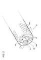
図5は、図3の構成のうち、撮像装置47だけを内視鏡先端部17から引き出した状態を示す外観斜視図である。対物レンズ群を収納した鏡筒45の背部に三角プリズム55が設けられ、三角プリズム55の出射面側に撮像素子59が設けられている。この撮像素子59を搭載したフレキシブルな回路基板57は、前述した様に、大きく折り曲げられて三角プリズム55の斜面に接着剤層89で貼り付けられている。 FIG. 5 is an external perspective view showing a state in which only the
撮像素子59の裏面側には、放熱シート88の下端側貼付部88aが貼り付けられており、この放熱シート88が、図5の紙面の向こう側で折り曲げられ、上端側貼付部88bが、回路基板57のケーブル接続部73(図3参照)に貼り付けられている。 A lower end
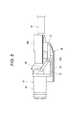
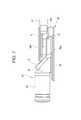
図6,図7,図8は、図5に示す撮像装置47の上面図、側面図、底面図である。放熱シート88は、撮像装置47のうち、鏡筒45と信号ケーブル61との間の部材(三角プリズム55、撮像素子59、回路基板57と信号ケーブル61との接続部)の底面、上面、1側面の3方を覆うように設けられている。撮像素子59の放熱経路が回路基板57と放熱シート88の2経路となって放熱性能が向上するが、更に本実施形態では、放熱シート88の内側の撮像装置47の凹凸部分が放熱シート88で覆われ、撮像装置47の内視鏡先端部17内への組み付けが容易となる。組み付け性を更に向上するために、撮像装置47の底面、上面、2側面の4方を放熱シート88で覆ってしまう構成としても良い。 6, 7, and 8 are a top view, a side view, and a bottom view of the
以上述べた実施形態の内視鏡装置及びその撮像素子放熱方法は、内視鏡先端部に内蔵され被写体からの入射光を受光する撮像素子と、該撮像素子及び撮像素子駆動回路部品が実装され前記内視鏡先端部に内蔵されるフレキシブルな回路基板とを備え、前記撮像素子の受光面以外の領域に直接又は他部材を介して放熱シートの一領域を貼り付け前記内視鏡先端部内の放熱部材に前記放熱シートの他領域を熱接触して前記撮像素子の熱を前記放熱部材に伝熱することを特徴とする。 The endoscope apparatus and the imaging element heat dissipation method of the embodiment described above are mounted with an imaging element built in the distal end portion of the endoscope that receives incident light from a subject, the imaging element, and an imaging element drive circuit component. A flexible circuit board built in the endoscope distal end, and a region of the heat radiating sheet is attached to the region other than the light receiving surface of the image sensor directly or via another member, in the endoscope distal end The other area of the heat dissipation sheet is in thermal contact with the heat dissipating member to transfer the heat of the imaging device to the heat dissipating member.
また、実施形態の内視鏡装置及びその撮像素子放熱方法は、前記回路基板の一領域が前記放熱部材に貼り付けられ、前記放熱シートの前記他領域が該回路基板の前記一領域に貼り付けられることで前記熱接触が図られることを特徴とする。 In the endoscope apparatus and the imaging element heat dissipation method according to the embodiment, one area of the circuit board is attached to the heat dissipation member, and the other area of the heat dissipation sheet is attached to the one area of the circuit board. In this case, the thermal contact is achieved.
また、実施形態の内視鏡装置及びその撮像素子放熱方法は、前記放熱シートは前記内蔵された前記回路基板の周囲で折り曲げられ該回路基板の周囲を包囲することを特徴とする。 In addition, the endoscope device and the imaging element heat dissipation method of the embodiment are characterized in that the heat dissipation sheet is bent around the built-in circuit board to surround the circuit board.
また、実施形態の内視鏡装置及びその撮像素子放熱方法は、前記放熱シートは、前記回路基板とは別のフレキシブルな回路基板であることを特徴とする。 Moreover, the endoscope apparatus and the imaging element heat dissipation method of the embodiment are characterized in that the heat dissipation sheet is a flexible circuit board different from the circuit board.
また、実施形態の内視鏡装置及びその撮像素子放熱方法は、前記放熱部材は、前記撮像素子及び前記撮像素子駆動回路部品に接続される配線を纏めた信号ケーブルであることを特徴とする。 In the endoscope apparatus and the imaging element heat dissipation method of the embodiment, the heat dissipation member is a signal cable in which wirings connected to the imaging element and the imaging element drive circuit component are combined.
以上述べた実施形態によれば、撮像素子の放熱経路が、回路基板を通した経路と放熱シートを通した経路の2経路用意され、良好な放熱性能を得ることが可能となる。これにより、撮像素子の駆動周波数を高周波化して撮像画像の高品質化を図ることが可能となり、また、撮像素子の多画素化を図ることも可能となる。 According to the embodiment described above, the heat dissipation path of the image pickup device is prepared in two paths, the path through the circuit board and the path through the heat dissipation sheet, and good heat dissipation performance can be obtained. As a result, the drive frequency of the image sensor can be increased to improve the quality of the captured image, and the number of pixels of the image sensor can be increased.
本発明に係る内視鏡装置は、撮像装置の放熱性能を向上させることができるため、撮像素子の多画素化,高速駆動化を図ることが可能となり、細径化,短尺化を図る内視鏡装置に適用すると有用である。 The endoscope apparatus according to the present invention can improve the heat dissipation performance of the image pickup apparatus, so that it is possible to increase the number of pixels of the image pickup element and increase the driving speed, and to reduce the diameter and length of the endoscope. It is useful when applied to a mirror device.
11 操作部
13 内視鏡挿入部
17 先端部
21 湾曲部
23,25 アングルノブ
33 鉗子口
37 観察窓
45 鏡筒
47 撮像装置
55 三角プリズム
57 フレキシブルな回路基板
59 撮像素子
61 信号ケーブル
73 回路基板のケーブル接続部
88 放熱シート
88a 撮像素子裏面側の貼付部
88b ケーブル接続部の貼付部
100 内視鏡装置DESCRIPTION OF
Claims (8)
Translated fromJapanese前記放熱シートは、前記一領域と、前記一領域に対向する前記他領域と、前記一領域と前記他領域を接続する折曲部とを有し、前記折曲部で折り曲げられて、前記回路基板の上面、底面、及び一側面を覆っている内視鏡装置。An image sensor that receives incident light from a subject that is built in the distal end portion of the endoscope, a flexible circuit board that is mounted with the image sensor and an image sensor driving circuit component and is built in the distal end portion of the endoscope, and the imaging A flexible heat radiating sheet in which one region is attached directly or through another member to a region other than the light receiving surface of the element, and the other region is in thermal contact with the heat radiating member in the endoscope distal end; and
The heat dissipation sheet has the one region, the other region facing the one region, and a bent portion connecting the one region and the other region, and is bent at the bent portion, so that the circuit An endoscope apparatuscovering an upper surface, a bottom surface, and one side surface of a substrate .
前記一領域と、前記一領域に対向する前記他領域と、前記一領域と前記他領域を接続する折曲部とを有する前記放熱シートを前記折曲部で折り曲げて、前記回路基板の上面、底面、及び一側面を前記放熱シートにより覆う内視鏡装置の撮像素子放熱方法。An image sensor that receives incident light from a subject that is built into the distal end portion of the endoscope, and a flexible circuit board that is mounted with the image sensor and the image sensor driving circuit component and is built in the distal end portion of the endoscope. An imaging element heat dissipation method for an endoscope apparatus, wherein a region of a heat dissipation sheet is pasted directly or via another member on a region other than a light receiving surface of the image sensor, and the heat dissipation sheet is disposed on a heat dissipation member in the distal end portion of the endoscope other areas in thermal contactwith the heat transfer the heat of the imaging element to the heat radiatingmember,
Bending the heat-dissipating sheet having the one region, the other region facing the one region, and a bent portion connecting the one region and the other region at the bent portion, An imaging element heat radiation method for an endoscope apparatus,wherein a bottom surface and one side surface arecovered with the heat radiation sheet .
Priority Applications (6)
| Application Number | Priority Date | Filing Date | Title |
|---|---|---|---|
| JP2010220072AJP5586402B2 (en) | 2010-09-29 | 2010-09-29 | Endoscope apparatus and imaging element heat dissipation method thereof |
| US13/247,141US9232197B2 (en) | 2010-09-29 | 2011-09-28 | Endoscope apparatus and method for releasing heat generated by imaging element of the endoscope apparatus |
| CN201110303555.XACN102551638B (en) | 2010-09-29 | 2011-09-29 | Endoscopic device and method for releasing heat generated by imaging elements of the endoscopic device |
| CN201510994112.8ACN105353505A (en) | 2010-09-29 | 2011-09-29 | Endoscope apparatus and method for releasing heat generated by imaging element of the endoscope apparatus |
| CN201510994086.9ACN105411507A (en) | 2010-09-29 | 2011-09-29 | Endoscope apparatus and method for releasing heat generated by imaging element of the endoscope apparatus |
| US14/950,540US20160080704A1 (en) | 2010-09-29 | 2015-11-24 | Endoscope apparatus and method for releasing heat generated by imaging element of the endoscope apparatus |
Applications Claiming Priority (1)
| Application Number | Priority Date | Filing Date | Title |
|---|---|---|---|
| JP2010220072AJP5586402B2 (en) | 2010-09-29 | 2010-09-29 | Endoscope apparatus and imaging element heat dissipation method thereof |
Publications (2)
| Publication Number | Publication Date |
|---|---|
| JP2012071064A JP2012071064A (en) | 2012-04-12 |
| JP5586402B2true JP5586402B2 (en) | 2014-09-10 |
Family
ID=45870259
Family Applications (1)
| Application Number | Title | Priority Date | Filing Date |
|---|---|---|---|
| JP2010220072AExpired - Fee RelatedJP5586402B2 (en) | 2010-09-29 | 2010-09-29 | Endoscope apparatus and imaging element heat dissipation method thereof |
Country Status (3)
| Country | Link |
|---|---|
| US (2) | US9232197B2 (en) |
| JP (1) | JP5586402B2 (en) |
| CN (3) | CN102551638B (en) |
Families Citing this family (16)
| Publication number | Priority date | Publication date | Assignee | Title |
|---|---|---|---|---|
| JP2011206079A (en)* | 2010-03-26 | 2011-10-20 | Fujifilm Corp | Imaging unit and endoscope |
| JP5386567B2 (en)* | 2011-11-15 | 2014-01-15 | 株式会社フジクラ | Imaging device chip mounting method, endoscope assembling method, imaging module, and endoscope |
| JP6218469B2 (en)* | 2013-07-17 | 2017-10-25 | キヤノン株式会社 | Imaging device |
| JP6411731B2 (en)* | 2013-12-04 | 2018-10-24 | オリンパス株式会社 | Imaging apparatus and endoscope |
| US10766431B2 (en)* | 2014-06-26 | 2020-09-08 | Kyocera Corporation | Imaging apparatus and vehicle |
| JP2016190007A (en)* | 2015-03-31 | 2016-11-10 | 株式会社フジクラ | Imaging module and endoscope |
| CN104997478A (en)* | 2015-05-29 | 2015-10-28 | 深圳开立生物医疗科技股份有限公司 | Endoscope hard portion provided with stereo circuit component and endoscope |
| JP6512522B2 (en)* | 2015-06-16 | 2019-05-15 | オリンパス株式会社 | Endoscope |
| GB2543509B (en)* | 2015-10-19 | 2020-10-14 | Creo Medical Ltd | Electrosurgical instrument |
| JP6630639B2 (en)* | 2016-07-11 | 2020-01-15 | 富士フイルム株式会社 | Endoscope |
| JP2018026395A (en)* | 2016-08-08 | 2018-02-15 | ソニーセミコンダクタソリューションズ株式会社 | Image sensor package and camera module |
| JP6650378B2 (en)* | 2016-09-08 | 2020-02-19 | 富士フイルム株式会社 | Endoscope |
| CN109005328B (en)* | 2018-08-31 | 2020-12-18 | 北京小米移动软件有限公司 | Camera module and electronic equipment |
| WO2021172002A1 (en)* | 2020-02-27 | 2021-09-02 | 富士フイルム株式会社 | Endoscope imaging device |
| DE212021000317U1 (en)* | 2020-05-25 | 2022-11-16 | Joymedicare (Shanghai) Medical Electronic Technology Co., Ltd | Heat dissipation structure of an insertion section of an endoscope |
| CN113712486B (en)* | 2020-05-25 | 2025-08-22 | 卓外(上海)医疗电子科技有限公司 | Endoscope insertion part heat dissipation structure |
Family Cites Families (33)
| Publication number | Priority date | Publication date | Assignee | Title |
|---|---|---|---|---|
| JPS6026918A (en)* | 1983-07-23 | 1985-02-09 | Fuji Photo Optical Co Ltd | Objective optical system for endoscope |
| JP2812940B2 (en)* | 1986-09-01 | 1998-10-22 | オリンパス光学工業株式会社 | Endoscope |
| JPH0673517B2 (en)* | 1988-02-04 | 1994-09-21 | オリンパス光学工業株式会社 | Electronic endoscope system |
| US5085496A (en)* | 1989-03-31 | 1992-02-04 | Sharp Kabushiki Kaisha | Optical element and optical pickup device comprising it |
| US5823941A (en)* | 1995-10-23 | 1998-10-20 | Shaunnessey; Jerome | Apparatus for directing the movement of an endoscopic surgical laser especially for use in vaporizing brain tumors |
| GB2312644B (en)* | 1996-05-02 | 2000-07-26 | Secr Defence Brit | Thermally insulating textile |
| JPH1099268A (en)* | 1996-09-30 | 1998-04-21 | Fuji Photo Optical Co Ltd | Optical device of electronic endoscope |
| BE1010730A7 (en)* | 1996-11-04 | 1998-12-01 | Pira Luc Louis Marie Francis | Cryoprobe based on peltier module. |
| JP2001203319A (en)* | 2000-01-18 | 2001-07-27 | Sony Corp | Laminated semiconductor device |
| JP2002299595A (en)* | 2001-04-03 | 2002-10-11 | Matsushita Electric Ind Co Ltd | Solid-state imaging device and method of manufacturing the same |
| JP2002344095A (en) | 2001-05-16 | 2002-11-29 | Matsushita Electric Ind Co Ltd | Composite circuit board |
| JP2003010111A (en) | 2001-06-27 | 2003-01-14 | Olympus Optical Co Ltd | Imaging device |
| JP2003024276A (en)* | 2001-07-13 | 2003-01-28 | Pentax Corp | Endoscope |
| US7275562B2 (en)* | 2001-10-17 | 2007-10-02 | Agilent Technologies, Inc. | Extensible spiral for flex circuit |
| KR100411631B1 (en)* | 2001-10-18 | 2003-12-18 | 주식회사 메디미르 | Fluorescence endoscope apparatus and a method for imaging tissue within a body using the same |
| JP3699040B2 (en)* | 2001-11-22 | 2005-09-28 | オリンパス株式会社 | Electronic endoscope |
| US6928380B2 (en)* | 2003-10-30 | 2005-08-09 | International Business Machines Corporation | Thermal measurements of electronic devices during operation |
| US7154175B2 (en)* | 2004-06-21 | 2006-12-26 | Intel Corporation | Ground plane for integrated circuit package |
| US7291981B2 (en)* | 2004-07-13 | 2007-11-06 | Perkinelmer, Inc | Short arc lamp with improved manufacturability |
| JP4542438B2 (en)* | 2005-01-17 | 2010-09-15 | オリンパスメディカルシステムズ株式会社 | Endoscope insertion part and endoscope |
| JP4788953B2 (en)* | 2005-11-16 | 2011-10-05 | ソニー株式会社 | Imaging device and zoom lens |
| JP2007240924A (en)* | 2006-03-09 | 2007-09-20 | Konica Minolta Holdings Inc | Head mount type video display apparatus |
| JP2008109378A (en)* | 2006-10-25 | 2008-05-08 | Matsushita Electric Ind Co Ltd | Optical device module and manufacturing method thereof, and optical device unit and manufacturing method thereof |
| JP4714665B2 (en)* | 2006-11-20 | 2011-06-29 | パナソニック株式会社 | Optical device module and manufacturing method thereof |
| JP2009082503A (en) | 2007-09-28 | 2009-04-23 | Fujifilm Corp | Imaging apparatus and endoscope provided with the imaging apparatus |
| JP2009181976A (en)* | 2008-01-29 | 2009-08-13 | Panasonic Corp | Solid-state imaging device and imaging device |
| CN102007824A (en)* | 2008-04-21 | 2011-04-06 | 住友电木株式会社 | Flexible wiring unit and electronic equipment |
| JP2010022815A (en)* | 2008-06-18 | 2010-02-04 | Olympus Corp | Endoscope apparatus |
| JP2010069217A (en) | 2008-09-22 | 2010-04-02 | Fujifilm Corp | Imaging apparatus for electronic endoscope and electronic endoscope |
| JP2010201023A (en)* | 2009-03-04 | 2010-09-16 | Fujifilm Corp | Endoscope |
| EP2471435B1 (en)* | 2009-08-24 | 2014-04-02 | Olympus Medical Systems Corp. | Medical apparatus |
| JP4842363B2 (en)* | 2009-11-17 | 2011-12-21 | シャープ株式会社 | Pointing device and electronic device |
| WO2011092903A1 (en)* | 2010-02-01 | 2011-08-04 | オリンパスメディカルシステムズ株式会社 | Image pickup unit for endoscope |
- 2010
- 2010-09-29JPJP2010220072Apatent/JP5586402B2/ennot_activeExpired - Fee Related
- 2011
- 2011-09-28USUS13/247,141patent/US9232197B2/ennot_activeExpired - Fee Related
- 2011-09-29CNCN201110303555.XApatent/CN102551638B/enactiveActive
- 2011-09-29CNCN201510994086.9Apatent/CN105411507A/enactivePending
- 2011-09-29CNCN201510994112.8Apatent/CN105353505A/enactivePending
- 2015
- 2015-11-24USUS14/950,540patent/US20160080704A1/ennot_activeAbandoned
Also Published As
| Publication number | Publication date |
|---|---|
| US20160080704A1 (en) | 2016-03-17 |
| CN102551638A (en) | 2012-07-11 |
| JP2012071064A (en) | 2012-04-12 |
| CN105411507A (en) | 2016-03-23 |
| CN105353505A (en) | 2016-02-24 |
| US20120075446A1 (en) | 2012-03-29 |
| US9232197B2 (en) | 2016-01-05 |
| CN102551638B (en) | 2016-01-13 |
Similar Documents
| Publication | Publication Date | Title |
|---|---|---|
| JP5586402B2 (en) | Endoscope apparatus and imaging element heat dissipation method thereof | |
| JP5514755B2 (en) | Endoscope imaging apparatus and endoscope apparatus | |
| EP2644084B1 (en) | Endoscope | |
| CN103648354B (en) | Fujinon electronic video endoscope | |
| JP5341279B2 (en) | Endoscope device | |
| JP5377085B2 (en) | Endoscope | |
| JP2009082503A (en) | Imaging apparatus and endoscope provided with the imaging apparatus | |
| JP6178749B2 (en) | Endoscopic imaging device | |
| JP2012050756A (en) | Endoscope apparatus, and method for radiating imaging element thereof | |
| WO2011092903A1 (en) | Image pickup unit for endoscope | |
| JP5740180B2 (en) | Imaging apparatus and endoscope apparatus | |
| JP6349286B2 (en) | Optical device, electronic endoscope, and manufacturing method of optical device | |
| JP4709870B2 (en) | Imaging device | |
| JP4127776B2 (en) | Imaging device | |
| JP5909406B2 (en) | Electronic endoscope apparatus and heat dissipation method for imaging element | |
| JP2003209751A (en) | Solid-state imaging apparatus | |
| JP2012050651A (en) | Imaging device and endoscope apparatus | |
| JP6018794B2 (en) | Electronic endoscope apparatus, imaging module for endoscope, and operation method of electronic endoscope apparatus | |
| JP7585104B2 (en) | Imaging module | |
| EP3123924A1 (en) | Endoscopic imaging device | |
| JP6820871B2 (en) | Endoscope and endoscope device | |
| JP5836189B2 (en) | Endoscopic imaging module and electronic endoscope apparatus | |
| JP6174747B2 (en) | Electronic endoscope apparatus and heat dissipation method for imaging element | |
| JP4286086B2 (en) | Endoscope device | |
| JP2022020547A (en) | Endoscope imaging apparatus and endoscope |
Legal Events
| Date | Code | Title | Description |
|---|---|---|---|
| RD03 | Notification of appointment of power of attorney | Free format text:JAPANESE INTERMEDIATE CODE: A7423 Effective date:20121005 | |
| A621 | Written request for application examination | Free format text:JAPANESE INTERMEDIATE CODE: A621 Effective date:20130111 | |
| A977 | Report on retrieval | Free format text:JAPANESE INTERMEDIATE CODE: A971007 Effective date:20131011 | |
| A131 | Notification of reasons for refusal | Free format text:JAPANESE INTERMEDIATE CODE: A131 Effective date:20131022 | |
| A521 | Request for written amendment filed | Free format text:JAPANESE INTERMEDIATE CODE: A523 Effective date:20131202 | |
| TRDD | Decision of grant or rejection written | ||
| A01 | Written decision to grant a patent or to grant a registration (utility model) | Free format text:JAPANESE INTERMEDIATE CODE: A01 Effective date:20140624 | |
| A61 | First payment of annual fees (during grant procedure) | Free format text:JAPANESE INTERMEDIATE CODE: A61 Effective date:20140722 | |
| R150 | Certificate of patent or registration of utility model | Ref document number:5586402 Country of ref document:JP Free format text:JAPANESE INTERMEDIATE CODE: R150 | |
| R250 | Receipt of annual fees | Free format text:JAPANESE INTERMEDIATE CODE: R250 | |
| R250 | Receipt of annual fees | Free format text:JAPANESE INTERMEDIATE CODE: R250 | |
| R250 | Receipt of annual fees | Free format text:JAPANESE INTERMEDIATE CODE: R250 | |
| R250 | Receipt of annual fees | Free format text:JAPANESE INTERMEDIATE CODE: R250 | |
| R250 | Receipt of annual fees | Free format text:JAPANESE INTERMEDIATE CODE: R250 | |
| R250 | Receipt of annual fees | Free format text:JAPANESE INTERMEDIATE CODE: R250 | |
| R250 | Receipt of annual fees | Free format text:JAPANESE INTERMEDIATE CODE: R250 | |
| LAPS | Cancellation because of no payment of annual fees |