JP5584223B2 - Surgical instrument for inserting an implant between two bones and method of use - Google Patents
Surgical instrument for inserting an implant between two bones and method of useDownload PDFInfo
- Publication number
- JP5584223B2 JP5584223B2JP2011532197AJP2011532197AJP5584223B2JP 5584223 B2JP5584223 B2JP 5584223B2JP 2011532197 AJP2011532197 AJP 2011532197AJP 2011532197 AJP2011532197 AJP 2011532197AJP 5584223 B2JP5584223 B2JP 5584223B2
- Authority
- JP
- Japan
- Prior art keywords
- implant
- surgical instrument
- elongate member
- assembly
- engagement
- Prior art date
- Legal status (The legal status is an assumption and is not a legal conclusion. Google has not performed a legal analysis and makes no representation as to the accuracy of the status listed.)
- Active
Links
Images


Classifications
- A—HUMAN NECESSITIES
- A61—MEDICAL OR VETERINARY SCIENCE; HYGIENE
- A61F—FILTERS IMPLANTABLE INTO BLOOD VESSELS; PROSTHESES; DEVICES PROVIDING PATENCY TO, OR PREVENTING COLLAPSING OF, TUBULAR STRUCTURES OF THE BODY, e.g. STENTS; ORTHOPAEDIC, NURSING OR CONTRACEPTIVE DEVICES; FOMENTATION; TREATMENT OR PROTECTION OF EYES OR EARS; BANDAGES, DRESSINGS OR ABSORBENT PADS; FIRST-AID KITS
- A61F2/00—Filters implantable into blood vessels; Prostheses, i.e. artificial substitutes or replacements for parts of the body; Appliances for connecting them with the body; Devices providing patency to, or preventing collapsing of, tubular structures of the body, e.g. stents
- A61F2/02—Prostheses implantable into the body
- A61F2/30—Joints
- A61F2/46—Special tools for implanting artificial joints
- A61F2/4603—Special tools for implanting artificial joints for insertion or extraction of endoprosthetic joints or of accessories thereof
- A61F2/4611—Special tools for implanting artificial joints for insertion or extraction of endoprosthetic joints or of accessories thereof of spinal prostheses
- A—HUMAN NECESSITIES
- A61—MEDICAL OR VETERINARY SCIENCE; HYGIENE
- A61F—FILTERS IMPLANTABLE INTO BLOOD VESSELS; PROSTHESES; DEVICES PROVIDING PATENCY TO, OR PREVENTING COLLAPSING OF, TUBULAR STRUCTURES OF THE BODY, e.g. STENTS; ORTHOPAEDIC, NURSING OR CONTRACEPTIVE DEVICES; FOMENTATION; TREATMENT OR PROTECTION OF EYES OR EARS; BANDAGES, DRESSINGS OR ABSORBENT PADS; FIRST-AID KITS
- A61F2/00—Filters implantable into blood vessels; Prostheses, i.e. artificial substitutes or replacements for parts of the body; Appliances for connecting them with the body; Devices providing patency to, or preventing collapsing of, tubular structures of the body, e.g. stents
- A61F2/02—Prostheses implantable into the body
- A61F2/30—Joints
- A61F2/44—Joints for the spine, e.g. vertebrae, spinal discs
- A—HUMAN NECESSITIES
- A61—MEDICAL OR VETERINARY SCIENCE; HYGIENE
- A61F—FILTERS IMPLANTABLE INTO BLOOD VESSELS; PROSTHESES; DEVICES PROVIDING PATENCY TO, OR PREVENTING COLLAPSING OF, TUBULAR STRUCTURES OF THE BODY, e.g. STENTS; ORTHOPAEDIC, NURSING OR CONTRACEPTIVE DEVICES; FOMENTATION; TREATMENT OR PROTECTION OF EYES OR EARS; BANDAGES, DRESSINGS OR ABSORBENT PADS; FIRST-AID KITS
- A61F2/00—Filters implantable into blood vessels; Prostheses, i.e. artificial substitutes or replacements for parts of the body; Appliances for connecting them with the body; Devices providing patency to, or preventing collapsing of, tubular structures of the body, e.g. stents
- A61F2/02—Prostheses implantable into the body
- A61F2/30—Joints
- A61F2/46—Special tools for implanting artificial joints
- A61F2/4637—Special tools for implanting artificial joints for connecting or disconnecting two parts of a prosthesis
- A—HUMAN NECESSITIES
- A61—MEDICAL OR VETERINARY SCIENCE; HYGIENE
- A61F—FILTERS IMPLANTABLE INTO BLOOD VESSELS; PROSTHESES; DEVICES PROVIDING PATENCY TO, OR PREVENTING COLLAPSING OF, TUBULAR STRUCTURES OF THE BODY, e.g. STENTS; ORTHOPAEDIC, NURSING OR CONTRACEPTIVE DEVICES; FOMENTATION; TREATMENT OR PROTECTION OF EYES OR EARS; BANDAGES, DRESSINGS OR ABSORBENT PADS; FIRST-AID KITS
- A61F2/00—Filters implantable into blood vessels; Prostheses, i.e. artificial substitutes or replacements for parts of the body; Appliances for connecting them with the body; Devices providing patency to, or preventing collapsing of, tubular structures of the body, e.g. stents
- A61F2/02—Prostheses implantable into the body
- A61F2/30—Joints
- A61F2002/30001—Additional features of subject-matter classified in A61F2/28, A61F2/30 and subgroups thereof
- A61F2002/30316—The prosthesis having different structural features at different locations within the same prosthesis; Connections between prosthetic parts; Special structural features of bone or joint prostheses not otherwise provided for
- A61F2002/30329—Connections or couplings between prosthetic parts, e.g. between modular parts; Connecting elements
- A61F2002/30471—Connections or couplings between prosthetic parts, e.g. between modular parts; Connecting elements connected by a hinged linkage mechanism, e.g. of the single-bar or multi-bar linkage type
- A—HUMAN NECESSITIES
- A61—MEDICAL OR VETERINARY SCIENCE; HYGIENE
- A61F—FILTERS IMPLANTABLE INTO BLOOD VESSELS; PROSTHESES; DEVICES PROVIDING PATENCY TO, OR PREVENTING COLLAPSING OF, TUBULAR STRUCTURES OF THE BODY, e.g. STENTS; ORTHOPAEDIC, NURSING OR CONTRACEPTIVE DEVICES; FOMENTATION; TREATMENT OR PROTECTION OF EYES OR EARS; BANDAGES, DRESSINGS OR ABSORBENT PADS; FIRST-AID KITS
- A61F2/00—Filters implantable into blood vessels; Prostheses, i.e. artificial substitutes or replacements for parts of the body; Appliances for connecting them with the body; Devices providing patency to, or preventing collapsing of, tubular structures of the body, e.g. stents
- A61F2/02—Prostheses implantable into the body
- A61F2/30—Joints
- A61F2002/30001—Additional features of subject-matter classified in A61F2/28, A61F2/30 and subgroups thereof
- A61F2002/30316—The prosthesis having different structural features at different locations within the same prosthesis; Connections between prosthetic parts; Special structural features of bone or joint prostheses not otherwise provided for
- A61F2002/30329—Connections or couplings between prosthetic parts, e.g. between modular parts; Connecting elements
- A61F2002/30476—Connections or couplings between prosthetic parts, e.g. between modular parts; Connecting elements locked by an additional locking mechanism
- A61F2002/30507—Connections or couplings between prosthetic parts, e.g. between modular parts; Connecting elements locked by an additional locking mechanism using a threaded locking member, e.g. a locking screw or a set screw
- A—HUMAN NECESSITIES
- A61—MEDICAL OR VETERINARY SCIENCE; HYGIENE
- A61F—FILTERS IMPLANTABLE INTO BLOOD VESSELS; PROSTHESES; DEVICES PROVIDING PATENCY TO, OR PREVENTING COLLAPSING OF, TUBULAR STRUCTURES OF THE BODY, e.g. STENTS; ORTHOPAEDIC, NURSING OR CONTRACEPTIVE DEVICES; FOMENTATION; TREATMENT OR PROTECTION OF EYES OR EARS; BANDAGES, DRESSINGS OR ABSORBENT PADS; FIRST-AID KITS
- A61F2/00—Filters implantable into blood vessels; Prostheses, i.e. artificial substitutes or replacements for parts of the body; Appliances for connecting them with the body; Devices providing patency to, or preventing collapsing of, tubular structures of the body, e.g. stents
- A61F2/02—Prostheses implantable into the body
- A61F2/30—Joints
- A61F2002/30001—Additional features of subject-matter classified in A61F2/28, A61F2/30 and subgroups thereof
- A61F2002/30316—The prosthesis having different structural features at different locations within the same prosthesis; Connections between prosthetic parts; Special structural features of bone or joint prostheses not otherwise provided for
- A61F2002/30329—Connections or couplings between prosthetic parts, e.g. between modular parts; Connecting elements
- A61F2002/30518—Connections or couplings between prosthetic parts, e.g. between modular parts; Connecting elements with possibility of relative movement between the prosthetic parts
- A61F2002/30523—Connections or couplings between prosthetic parts, e.g. between modular parts; Connecting elements with possibility of relative movement between the prosthetic parts by means of meshing gear teeth
- A—HUMAN NECESSITIES
- A61—MEDICAL OR VETERINARY SCIENCE; HYGIENE
- A61F—FILTERS IMPLANTABLE INTO BLOOD VESSELS; PROSTHESES; DEVICES PROVIDING PATENCY TO, OR PREVENTING COLLAPSING OF, TUBULAR STRUCTURES OF THE BODY, e.g. STENTS; ORTHOPAEDIC, NURSING OR CONTRACEPTIVE DEVICES; FOMENTATION; TREATMENT OR PROTECTION OF EYES OR EARS; BANDAGES, DRESSINGS OR ABSORBENT PADS; FIRST-AID KITS
- A61F2/00—Filters implantable into blood vessels; Prostheses, i.e. artificial substitutes or replacements for parts of the body; Appliances for connecting them with the body; Devices providing patency to, or preventing collapsing of, tubular structures of the body, e.g. stents
- A61F2/02—Prostheses implantable into the body
- A61F2/30—Joints
- A61F2002/30001—Additional features of subject-matter classified in A61F2/28, A61F2/30 and subgroups thereof
- A61F2002/30316—The prosthesis having different structural features at different locations within the same prosthesis; Connections between prosthetic parts; Special structural features of bone or joint prostheses not otherwise provided for
- A61F2002/30535—Special structural features of bone or joint prostheses not otherwise provided for
- A61F2002/30537—Special structural features of bone or joint prostheses not otherwise provided for adjustable
- A61F2002/3055—Special structural features of bone or joint prostheses not otherwise provided for adjustable for adjusting length
- A—HUMAN NECESSITIES
- A61—MEDICAL OR VETERINARY SCIENCE; HYGIENE
- A61F—FILTERS IMPLANTABLE INTO BLOOD VESSELS; PROSTHESES; DEVICES PROVIDING PATENCY TO, OR PREVENTING COLLAPSING OF, TUBULAR STRUCTURES OF THE BODY, e.g. STENTS; ORTHOPAEDIC, NURSING OR CONTRACEPTIVE DEVICES; FOMENTATION; TREATMENT OR PROTECTION OF EYES OR EARS; BANDAGES, DRESSINGS OR ABSORBENT PADS; FIRST-AID KITS
- A61F2/00—Filters implantable into blood vessels; Prostheses, i.e. artificial substitutes or replacements for parts of the body; Appliances for connecting them with the body; Devices providing patency to, or preventing collapsing of, tubular structures of the body, e.g. stents
- A61F2/02—Prostheses implantable into the body
- A61F2/30—Joints
- A61F2002/30001—Additional features of subject-matter classified in A61F2/28, A61F2/30 and subgroups thereof
- A61F2002/30316—The prosthesis having different structural features at different locations within the same prosthesis; Connections between prosthetic parts; Special structural features of bone or joint prostheses not otherwise provided for
- A61F2002/30535—Special structural features of bone or joint prostheses not otherwise provided for
- A61F2002/30604—Special structural features of bone or joint prostheses not otherwise provided for modular
- A61F2002/30616—Sets comprising a plurality of prosthetic parts of different sizes or orientations
- A—HUMAN NECESSITIES
- A61—MEDICAL OR VETERINARY SCIENCE; HYGIENE
- A61F—FILTERS IMPLANTABLE INTO BLOOD VESSELS; PROSTHESES; DEVICES PROVIDING PATENCY TO, OR PREVENTING COLLAPSING OF, TUBULAR STRUCTURES OF THE BODY, e.g. STENTS; ORTHOPAEDIC, NURSING OR CONTRACEPTIVE DEVICES; FOMENTATION; TREATMENT OR PROTECTION OF EYES OR EARS; BANDAGES, DRESSINGS OR ABSORBENT PADS; FIRST-AID KITS
- A61F2/00—Filters implantable into blood vessels; Prostheses, i.e. artificial substitutes or replacements for parts of the body; Appliances for connecting them with the body; Devices providing patency to, or preventing collapsing of, tubular structures of the body, e.g. stents
- A61F2/02—Prostheses implantable into the body
- A61F2/30—Joints
- A61F2/46—Special tools for implanting artificial joints
- A61F2/4603—Special tools for implanting artificial joints for insertion or extraction of endoprosthetic joints or of accessories thereof
- A61F2002/4622—Special tools for implanting artificial joints for insertion or extraction of endoprosthetic joints or of accessories thereof having the shape of a forceps or a clamp
- A—HUMAN NECESSITIES
- A61—MEDICAL OR VETERINARY SCIENCE; HYGIENE
- A61F—FILTERS IMPLANTABLE INTO BLOOD VESSELS; PROSTHESES; DEVICES PROVIDING PATENCY TO, OR PREVENTING COLLAPSING OF, TUBULAR STRUCTURES OF THE BODY, e.g. STENTS; ORTHOPAEDIC, NURSING OR CONTRACEPTIVE DEVICES; FOMENTATION; TREATMENT OR PROTECTION OF EYES OR EARS; BANDAGES, DRESSINGS OR ABSORBENT PADS; FIRST-AID KITS
- A61F2/00—Filters implantable into blood vessels; Prostheses, i.e. artificial substitutes or replacements for parts of the body; Appliances for connecting them with the body; Devices providing patency to, or preventing collapsing of, tubular structures of the body, e.g. stents
- A61F2/02—Prostheses implantable into the body
- A61F2/30—Joints
- A61F2/46—Special tools for implanting artificial joints
- A61F2/4603—Special tools for implanting artificial joints for insertion or extraction of endoprosthetic joints or of accessories thereof
- A61F2002/4625—Special tools for implanting artificial joints for insertion or extraction of endoprosthetic joints or of accessories thereof with relative movement between parts of the instrument during use
- A61F2002/4627—Special tools for implanting artificial joints for insertion or extraction of endoprosthetic joints or of accessories thereof with relative movement between parts of the instrument during use with linear motion along or rotating motion about the instrument axis or the implantation direction, e.g. telescopic, along a guiding rod, screwing inside the instrument
- A—HUMAN NECESSITIES
- A61—MEDICAL OR VETERINARY SCIENCE; HYGIENE
- A61F—FILTERS IMPLANTABLE INTO BLOOD VESSELS; PROSTHESES; DEVICES PROVIDING PATENCY TO, OR PREVENTING COLLAPSING OF, TUBULAR STRUCTURES OF THE BODY, e.g. STENTS; ORTHOPAEDIC, NURSING OR CONTRACEPTIVE DEVICES; FOMENTATION; TREATMENT OR PROTECTION OF EYES OR EARS; BANDAGES, DRESSINGS OR ABSORBENT PADS; FIRST-AID KITS
- A61F2/00—Filters implantable into blood vessels; Prostheses, i.e. artificial substitutes or replacements for parts of the body; Appliances for connecting them with the body; Devices providing patency to, or preventing collapsing of, tubular structures of the body, e.g. stents
- A61F2/02—Prostheses implantable into the body
- A61F2/30—Joints
- A61F2/46—Special tools for implanting artificial joints
- A61F2/4603—Special tools for implanting artificial joints for insertion or extraction of endoprosthetic joints or of accessories thereof
- A61F2002/4625—Special tools for implanting artificial joints for insertion or extraction of endoprosthetic joints or of accessories thereof with relative movement between parts of the instrument during use
- A61F2002/4628—Special tools for implanting artificial joints for insertion or extraction of endoprosthetic joints or of accessories thereof with relative movement between parts of the instrument during use with linear motion along or rotating motion about an axis transverse to the instrument axis or to the implantation direction, e.g. clamping
- A—HUMAN NECESSITIES
- A61—MEDICAL OR VETERINARY SCIENCE; HYGIENE
- A61F—FILTERS IMPLANTABLE INTO BLOOD VESSELS; PROSTHESES; DEVICES PROVIDING PATENCY TO, OR PREVENTING COLLAPSING OF, TUBULAR STRUCTURES OF THE BODY, e.g. STENTS; ORTHOPAEDIC, NURSING OR CONTRACEPTIVE DEVICES; FOMENTATION; TREATMENT OR PROTECTION OF EYES OR EARS; BANDAGES, DRESSINGS OR ABSORBENT PADS; FIRST-AID KITS
- A61F2220/00—Fixations or connections for prostheses classified in groups A61F2/00 - A61F2/26 or A61F2/82 or A61F9/00 or A61F11/00 or subgroups thereof
- A61F2220/0025—Connections or couplings between prosthetic parts, e.g. between modular parts; Connecting elements
- A61F2220/0091—Connections or couplings between prosthetic parts, e.g. between modular parts; Connecting elements connected by a hinged linkage mechanism, e.g. of the single-bar or multi-bar linkage type
Landscapes
- Health & Medical Sciences (AREA)
- Transplantation (AREA)
- Engineering & Computer Science (AREA)
- Biomedical Technology (AREA)
- Orthopedic Medicine & Surgery (AREA)
- Oral & Maxillofacial Surgery (AREA)
- Physical Education & Sports Medicine (AREA)
- Cardiology (AREA)
- Neurology (AREA)
- Heart & Thoracic Surgery (AREA)
- Vascular Medicine (AREA)
- Life Sciences & Earth Sciences (AREA)
- Animal Behavior & Ethology (AREA)
- General Health & Medical Sciences (AREA)
- Public Health (AREA)
- Veterinary Medicine (AREA)
- Prostheses (AREA)
- Surgical Instruments (AREA)
Description
Translated fromJapanese本発明は、概して整形外科及び脳神経外科の器具類及び技術に関し、排他的ではないが、より具体的には、二つの骨の間に装置を移植するのに使用されるべき挿入具に関する。 The present invention relates generally to orthopedic and neurosurgical instruments and techniques, and more specifically, but not exclusively, to an inserter to be used to implant a device between two bones.
骨構造の一体構造(integral structure)に影響する損傷又は病気、又はより具体的には個人の脊柱内の椎体に影響する損傷又は病気は、周辺組織への永久的な損傷を伴うことがある神経機能障害を引き起こすことがある。骨構造及び脊柱において適切な解剖学的空間を維持することは、周辺組織、脊柱、脊髄、及び神経根の継続的な機能を確保するのに極めて重要であり、ひいては長期間に亘る深刻な神経機能障害の回避のために極めて重要である。 Damage or illness that affects the integral structure of the bone structure, or more specifically, damage or illness that affects the vertebral body in an individual's spinal column may involve permanent damage to surrounding tissue. May cause neurological dysfunction. Maintaining adequate anatomical space in the bone structure and spinal column is critical to ensuring the continued functioning of the surrounding tissues, spinal column, spinal cord, and nerve roots, and thus long-term serious nerves It is extremely important for avoiding dysfunction.
典型的には、スペ−サ型の装置として使用される脊椎インプラントは、固定された全長を有し、且つ、複合的な挿入器具類を使用しなければ拡張又は湾曲の度合いを調整することができない状態で移植される。スペーサ型のインプラントを移植するのに使用されるべき多目的器具であって、外科医が、切開創の大きさを最小にし、手術技術を容易にし、且つ患者の罹患率を減少させることを可能とする多目的器具についての要求が依然として存在する。 Typically, spinal implants used as a spacer-type device have a fixed overall length and can adjust the degree of expansion or curvature unless complex insertion instruments are used. It is transplanted in a state where it cannot. A multipurpose instrument to be used to implant a spacer-type implant that allows a surgeon to minimize the size of the incision, facilitate surgical techniques and reduce patient morbidity There is still a need for multipurpose instruments.
二つの骨の間における装置、より具体的には、無傷の脊柱内における欠落し又は損傷した椎体を有する患者の外科的処置において使用される脊椎インプラントを移植するのに使用される手術器具類の状態の進歩は、望ましいものと考えられている。本発明は、多機能の器具を提供することによって、骨スペーサ装置及びインプラント、より具体的には、病気に冒された椎体又は損傷した椎体に苦しむ患者内に移植される脊椎スペーサ装置を挿入し且つ調整するのに使用される手術器具に対する改善要求を満たし、多機能の器具は、手術医が、可変長の椎体置換装置を掴んでその長さを変化させ且つ傷口及び脊柱内への挿入の後に可変長の椎体置換装置を繋止することを可能とする。 Surgical instruments used to implant devices between two bones, more specifically spinal implants used in surgical procedures for patients with missing or damaged vertebral bodies in an intact spinal column The progress of the state is considered desirable. The present invention provides a bone spacer device and implant, more specifically a spinal spacer device that is implanted in a patient suffering from a diseased or damaged vertebral body by providing a multifunctional instrument. Satisfying the need for improvement on surgical instruments used to insert and adjust, a multi-functional instrument allows a surgeon to grasp a variable length vertebral body replacement device and change its length and into the wound and spinal column It is possible to lock the variable length vertebral body replacement device after insertion.
本発明の一つの態様では、二つの骨の間にインプラントを挿入するための手術器具であって、ハンドル及び細長部材を含む手術器具が提供され、細長部材は、第1端部及び第2端部を有し、長手方向の軸線がこれら二つの端部の間に延在し、第2端部はインプラント係合組立体に移動可能に連結され、インプラント係合組立体は手術器具の遠位端部に定置される。インプラント係合組立体はインプラントを保持するように構成される。インプラント係合組立体に対する細長部材の移動によって、インプラント係合組立体によるインプラントの調整がもたらされ、手術医は二つの骨の間にインプラントを設置できるようになる。 In one aspect of the present invention, there is provided a surgical instrument for inserting an implant between two bones, the surgical instrument including a handle and an elongated member, the elongated member having a first end and a second end. And a longitudinal axis extends between the two ends, the second end is movably connected to the implant engagement assembly, and the implant engagement assembly is distal to the surgical instrument. Placed at the end. The implant engagement assembly is configured to hold the implant. Movement of the elongate member relative to the implant engagement assembly provides adjustment of the implant by the implant engagement assembly and allows the surgeon to place the implant between the two bones.
本発明の別の態様では、二つの椎骨(vertebra)の間に脊椎インプラントを挿入するための手術器具であって、手術器具の近位端部に位置するハンドル組立体と、細長部材とを含む手術器具が提供され、細長部材は第1端部及び第2端部を有し、長手方向の軸線が二つの端部の間に延在する。第1端部はハンドル組立体に近接して配設され、第2端部は脊椎インプラント係合組立体に回転可能に連結されるように構成され、脊椎インプラント係合組立体は手術器具の遠位端部に定置される。手術器具は、脊椎インプラントが二つの椎骨の間に設置されたときに脊椎インプラントの全長を調整するための長さ制御機構も含む。長さ制御機構は、把持部、歯車組立体、及び駆動シャフトから構築され、駆動シャフトは把持部と歯車組立体との間に定置される。駆動シャフトはハンドル組立体内における第1の穴を通って延在し且つ細長部材の長手方向の軸線に対してほぼ平行に向けられる。手術器具は、脊椎インプラントが二つの椎骨の間に設置された後に脊椎インプラントの全長部分を繋止するための第1ロック機構を更に含む。第1ロック機構は、手術器具の近位端部の直近にある把持部と、結合端部と、連結ロッドとを有し、連結ロッドは把持部と結合端部との間にある。連結ロッドはハンドル組立体内における第2の穴を通って延在し且つ細長部材の長手方向の軸線に対してほぼ平行に向けられる。 In another aspect of the invention, a surgical instrument for inserting a spinal implant between two vertebras, comprising a handle assembly located at the proximal end of the surgical instrument and an elongate member A surgical instrument is provided, wherein the elongate member has a first end and a second end, and a longitudinal axis extends between the two ends. The first end is disposed proximate to the handle assembly and the second end is configured to be rotatably coupled to the spinal implant engagement assembly, the spinal implant engagement assembly being remote from the surgical instrument. It is fixed at the end. The surgical instrument also includes a length control mechanism for adjusting the overall length of the spinal implant when the spinal implant is placed between the two vertebrae. The length control mechanism is constructed from a gripping part, a gear assembly, and a drive shaft, and the drive shaft is placed between the gripping part and the gear assembly. The drive shaft extends through the first hole in the handle assembly and is oriented substantially parallel to the longitudinal axis of the elongated member. The surgical instrument further includes a first locking mechanism for locking the full length portion of the spinal implant after the spinal implant is placed between the two vertebrae. The first locking mechanism has a gripping portion in the immediate vicinity of the proximal end portion of the surgical instrument, a coupling end portion, and a connecting rod, and the connecting rod is between the gripping portion and the coupling end portion. The connecting rod extends through the second hole in the handle assembly and is oriented substantially parallel to the longitudinal axis of the elongated member.
本発明の更に別の態様では、二つの骨の間にインプラントを挿入するための手術方法が提供され、この手術方法は、二つの骨の位置の直近にある患者の皮膚上に穴を外科的に生成するステップを含む。本方法は、手術器具を得るステップを更に含み、手術器具は、ハンドル組立体と、第1端部及び第2端部を有する細長部材と、二つの端部の間に延在する長手方向の軸線とを有する。第1端部はハンドル組立体に近接して定置され、第2端部はインプラント係合組立体に移動可能に連結され、インプラント係合組立体は手術器具の遠位端部に配設される。手術器具は、インプラントが二つの骨の間に設置されたときにインプラントの全長を調整するための長さ制御機構も有し、長さ制御機構は、把持部と、歯車組立体と、把持部と歯車組立体との間にある駆動シャフトとを有する。駆動シャフトはハンドル組立体内における第1の穴を通って延在し且つ細長部材の長手方向の軸線に対してほぼ平行に向けられるように構成される。手術器具は、インプラントが二つの骨の間に設置された後にインプラントの全長部分を繋止するための少なくとも一つのロック機構を更に含む。少なくとも一つのロック機構は、手術器具の遠位端部の直近にある把持部と、結合端部と、把持部と結合端部との間にある連結ロッドとを有する。連結ロッドはハンドル組立体内における第2の穴を通って延在し且つ細長部材の長手方向の軸線に対してほぼ平行に向けられる。手術方法は、通常、インプラントをインプラント係合組立体に結合するステップと、その後、手術器具及び結合されたインプラントを皮膚の穴内に挿入するステップを更に含む。手術方法は、二つの骨の間における空間内にインプラントを定置するステップを更に含むことができる。本方法の更なるステップは、二つの骨の間に空間を維持するために、インプラントを全長に伸長させて二つの骨に接触させ且つ二つの骨に力を印加することでありうる。典型的には、手術方法は、挿入されたインプラントの全長部分を固定し又は繋止する更に別のステップを含む。 In yet another aspect of the present invention, a surgical method is provided for inserting an implant between two bones, the surgical method surgically drilling a hole on the patient's skin proximate to the location of the two bones. Generating a step. The method further includes obtaining a surgical instrument, the surgical instrument comprising a handle assembly, an elongate member having a first end and a second end, and a longitudinal direction extending between the two ends. Axis. The first end is positioned proximate to the handle assembly, the second end is movably coupled to the implant engagement assembly, and the implant engagement assembly is disposed at the distal end of the surgical instrument. . The surgical instrument also has a length control mechanism for adjusting the total length of the implant when the implant is placed between two bones, the length control mechanism comprising a gripping portion, a gear assembly, and a gripping portion. And a drive shaft between the gear assembly. The drive shaft is configured to extend through the first hole in the handle assembly and to be oriented substantially parallel to the longitudinal axis of the elongate member. The surgical instrument further includes at least one locking mechanism for locking the full length portion of the implant after the implant is placed between the two bones. At least one locking mechanism has a gripping portion proximate to the distal end of the surgical instrument, a coupling end, and a connecting rod between the gripping portion and the coupling end. The connecting rod extends through the second hole in the handle assembly and is oriented substantially parallel to the longitudinal axis of the elongated member. The surgical method typically further includes coupling the implant to the implant engagement assembly and then inserting the surgical instrument and the coupled implant into the skin hole. The surgical method can further include placing the implant in a space between the two bones. A further step of the method may be to extend the implant to full length to contact the two bones and to apply a force to the two bones in order to maintain a space between the two bones. Typically, the surgical method includes a further step of securing or locking the full length portion of the inserted implant.
本発明の別の態様では、手術器具の製造方法が提供される。本方法は、ハンドル組立体を提供するステップを含むことができる。製造方法は、細長部材を提供するステップを更に含むことができ、細長部材は第1端部及び第2端部を有し、長手方向の軸線が二つの端部の間に延在する。第1端部はハンドル組立体に近接して定置され、第2端部はインプラント係合組立体に移動可能に連結され、インプラント係合組立体は手術器具の遠位端部に配設される。ハンドル組立体及びインプラント係合組立体に対する細長部材の移動によって、インプラント係合組立体はインプラントに結合され、二つの骨の間におけるインプラントの設置が可能となる。 In another aspect of the invention, a method for manufacturing a surgical instrument is provided. The method can include providing a handle assembly. The manufacturing method can further include providing an elongate member, the elongate member having a first end and a second end, with a longitudinal axis extending between the two ends. The first end is positioned proximate to the handle assembly, the second end is movably coupled to the implant engagement assembly, and the implant engagement assembly is disposed at the distal end of the surgical instrument. . Movement of the elongate member relative to the handle assembly and the implant engagement assembly couples the implant engagement assembly to the implant and allows placement of the implant between the two bones.
本発明の更なる態様では、二つの椎骨の間に設置されるべき脊椎インプラントと、手術器具とを含む脊椎インプラント挿入キットが提供され、手術器具はハンドル組立体及び細長部材を有し、細長部材は第1端部及び第2端部を有し、長手方向の軸線が二つの端部の間に延在する。第1端部はハンドル組立体に近接して定置され、第2端部は、手術器具の遠位端部にある脊椎インプラント係合組立体に移動可能に連結される。手術器具は、脊椎インプラントが二つの椎体の間に設置されたときに脊椎インプラントの全長を調整するための長さ制御機構も有する。長さ制御機構は、把持部と、歯車組立体と、把持部と歯車組立体との間に定置された駆動シャフトとを有し、駆動シャフトはハンドル組立体内における第1の穴を通って延在する。また、装置のシャフトは細長部材の長手方向の軸線に対してほぼ平行に向けられる。手術器具は、脊椎インプラントが二つの骨の間に設置された後に脊椎インプラントの全長部分を繋止するための少なくとも一つのロック機構も含む。少なくとも一つのロック機構は、手術器具の近位端部の直近にある把持部と、結合端部と、把持部と結合端部との間にある連結ロッドとを有する。連結ロッドはハンドル組立体内における第2の孔を通って延在し且つ細長部材の長手方向の軸線に対してほぼ平行に向けられる。 In a further aspect of the invention, a spinal implant insertion kit is provided that includes a spinal implant to be placed between two vertebrae and a surgical instrument, the surgical instrument having a handle assembly and an elongated member, the elongated member Has a first end and a second end, with a longitudinal axis extending between the two ends. The first end is positioned proximate to the handle assembly and the second end is movably coupled to a spinal implant engagement assembly at the distal end of the surgical instrument. The surgical instrument also has a length control mechanism for adjusting the overall length of the spinal implant when the spinal implant is placed between the two vertebral bodies. The length control mechanism includes a gripper, a gear assembly, and a drive shaft positioned between the gripper and the gear assembly, the drive shaft extending through a first hole in the handle assembly. Exists. Also, the shaft of the device is oriented substantially parallel to the longitudinal axis of the elongated member. The surgical instrument also includes at least one locking mechanism for locking the full length portion of the spinal implant after the spinal implant is placed between the two bones. The at least one locking mechanism includes a gripping portion proximate to the proximal end of the surgical instrument, a coupling end, and a connecting rod between the gripping portion and the coupling end. The connecting rod extends through the second hole in the handle assembly and is oriented substantially parallel to the longitudinal axis of the elongated member.
更に、追加の特徴及び利点が本発明の技術を通して理解される。本発明の他の実施形態及び態様が、本明細書において詳細に記述され、且つ、請求された発明の一部と見なされる。 In addition, additional features and advantages are realized through the techniques of the present invention. Other embodiments and aspects of the invention are described in detail herein and are considered a part of the claimed invention.
本発明として見なされる対象は、明細書の結びにおける特許請求の範囲において特別に指定されて別個に請求される。添付の図面と併用される以下の詳細な記述から、前述の目的及び他の目的並びに本発明の特徴及び利点が明白である。
概して述べると、二つの骨の間における空間内にインプラントを挿入するのに使用される手術器具が本明細書において開示される。より具体的には、本手術器具は、典型的には、脊柱内への移植の間、椎体置換インプラントを保持し、伸長/収縮させ、且つロックするのに使用されるであろう。本手術器具は、概して、ハンドル組立体及び細長部材を含み、細長部材は遠位端部にインプラント係合組立体を含む。インプラント係合組立体は作動体及びインプラント保持部を更に含み、インプラント保持部は、作動体が作動されるときにインプラントを移動させて掴む二つのアームを有する。本手術器具は長さ制御機構及び長さロック機構を更に含む。長さ制御機構の遠位端部又は長さ制御機構の歯車組立体が、インプラントの全長を変えることを可能とすべく、インプラント内に挿入されて、対応する長さ調整機構に結合する。典型的には、本手術器具はロック機構を更に含み、ロック機構は、インプラントの全長部分を固定すべく、インプラント内にロックピン又はロックネジを挿入させる。The subject matter regarded as the invention is specifically designated and claimed separately in the claims at the end of the specification. The foregoing and other objects as well as the features and advantages of the present invention are apparent from the following detailed description taken in conjunction with the accompanying drawings.
Generally speaking, a surgical instrument used to insert an implant into a space between two bones is disclosed herein. More specifically, the surgical instrument will typically be used to hold, extend / contract and lock a vertebral body replacement implant during implantation into the spinal column. The surgical instrument generally includes a handle assembly and an elongate member, the elongate member including an implant engagement assembly at a distal end. The implant engagement assembly further includes an actuating body and an implant holding portion, the implant holding portion having two arms that move and grasp the implant when the actuating body is actuated. The surgical instrument further includes a length control mechanism and a length lock mechanism. A distal end of the length control mechanism or a gear assembly of the length control mechanism is inserted into the implant and coupled to a corresponding length adjustment mechanism to allow changing the overall length of the implant. Typically, the surgical instrument further includes a locking mechanism that causes a locking pin or locking screw to be inserted into the implant to secure the full length portion of the implant.
本明細書において用いられるような、「手術器具」及び「挿入具」の用語は、基本的には同じ種類の手術器具について記述するように置換可能に用いられることができる。さらに、本明細書において、手術器具を使用するための手術方法、手術器具を製造する方法、及び脊椎インプラント挿入キットが記述され、脊椎インプラント挿入キットは、病気に冒された脊柱又は損傷された脊柱に苦しむ患者内において、二つの椎骨の間に空間を維持するのに使用される。 As used herein, the terms “surgical instrument” and “insertion tool” can be used interchangeably to describe essentially the same type of surgical instrument. Further described herein is a surgical method for using a surgical instrument, a method of manufacturing a surgical instrument, and a spinal implant insertion kit, wherein the spinal implant insertion kit is a diseased or damaged spinal column. It is used to maintain a space between two vertebrae in patients suffering from
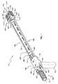
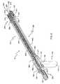
図1、図3、及び図4において描写されるように、本発明の一つの態様に係る手術器具10の一般的な配置は、ハンドル組立体100、細長部材201、インプラント係合組立体204、長さ制御機構300、及び少なくとも一つのロック機構400を含む。手術器具10は、インプラントが体内に設置されるとき、インプラントの長さ部分を掴んで拡張及び収縮し且つインプラントの全長部分を繋止するのに使用されるべきである。手術器具10と共に使用されうるインプラントの一つの種類が、同時係属中の米国特許出願第11/928532号明細書及び米国特許第11/928553号明細書において記述されるインプラントである。これら二つの係属中の米国特許出願において提供される内容及び開示は参照によって本明細書の一部を構成する。 As depicted in FIGS. 1, 3, and 4, the general arrangement of a
この詳細な記述及び以下の特許請求の範囲において、近位、遠位、前、後、中間、横、上、及び下といった言葉は、手術器具の相対的な配置に準じた、骨、プロテーゼ、若しくは手術器具の特定部分、又は方向の参照用語を示すために、これらの標準的な用法によって定義される。例えば、「近位」は、器具の胴体(torso)の最も近くに定置された、器具の部分を意味し、一方、「遠位」は、胴体から最も遠い、器具の部分を示す。方向の用語に関しては、「前」は、本体の正面に向かう方向であり、「後」は、本体の背後に向かう方向を意味し、「中間」は、本体の中間線に向かう方向を意味し、「横」は、本体の側部に向かう方向又は本体の中間線から離れる方向であり、「上」は別の物体又は別の構造よりも上の方向を意味し、且つ、「下」は別の物体又は別の構造よりも下の方向を意味する。 In this detailed description and the following claims, the terms proximal, distal, front, back, middle, side, top, and bottom refer to bone, prosthesis, according to the relative placement of surgical instruments. Or they are defined by these standard usages to indicate specific parts of a surgical instrument, or directional reference terms. For example, “proximal” refers to the portion of the instrument that is placed closest to the torso of the instrument, while “distal” refers to the part of the instrument that is farthest from the torso. Regarding the direction terminology, “front” means the direction toward the front of the body, “back” means the direction toward the back of the body, and “middle” means the direction toward the middle line of the body. , "Lateral" is the direction towards the side of the body or away from the middle line of the body, "up" means the direction above another object or another structure, and "down" means It means a direction below another object or another structure.
図1及び図3を参照すると、手術器具10は、ハンドル組立体100、細長部材201、及びインプラント係合組立体204を含み、インプラント係合組立体204は、作動体205、整列体214、及び保持部206を更に含む。手術器具10は長さ制御機構300及び少なくとも一つのロック機構400を更に含み、少なくとも一つのロック機構400は細長部材201の長手方向の軸線210に対して平行に延びるように向けられる。 With reference to FIGS. 1 and 3, the
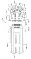
図1において示されるように、手術器具10のハンドル組立体100は本体部分101及び頂部102も含む。本体部分101は手術医の掌及び指に適応するように概して把持部又は保持部として構成される。本体部分101は、手術器具10が、様々な使用者の手の大きさに合うだけでなく、内視鏡手術及び内視鏡的アプローチを含む広範な外科的用途において器用さ及び快適性を犠牲にすることなく使用されることができるように大きさ及び構成が変えられて使用可能であると考えられる。少なくとも一つの貫通孔103が頂部において中心に位置し且つ近位から遠位への方向に延在する。孔103は、遠位方向に突出するカニューレチューブ304(図8参照)を受容して固定するように特定の大きさで作られて、カニューレチューブ304は、長さ制御機構300の部品である駆動シャフト303を収納する。 As shown in FIG. 1, the
図1及び図8において見られるように、ほぼ平行な二つの貫通孔104が孔103の両側に定置され且つ少なくとも一つのロック機構400についての連結ロッド403を受容するように特定の大きさで作られる。図8において例示の目的で示される実施形態では、ほぼ平行な二つの孔104が描写され、ほぼ平行な二つの孔104はロック機構400の連結ロッド403を受容するように特定の大きさで作られる。孔104は、手術医が手術器具10を使用しているときにインプラントの全長部分を繋止すべく連結ロッド403の回転運動を可能とするように構成される。 As can be seen in FIGS. 1 and 8, two substantially parallel through
細長部材201がハンドル組立体100と作動体205との間に定置される。図1、図3、及び図4は細長本体201を示し、細長本体201は近位から遠位への方向に延在し、第1端部202がハンドル組立体100に近接して配設され、第2端部203が、遠位方向に定置されたインプラント係合組立体204、又はより具体的には作動体205に移動可能又は回転可能に連結される。図1、図2、図3、及び図4において見られるように、細長部材201は円形の断面形状を有するチューブ状構造であるが、更に、様々な幾何学的な形状断面が細長部材201を構築するのに使用されてもよいと考えられ、様々な幾何学的な形状断面は、限定されるものではないが、楕円、正方形、長方形、及び他の多角形を含む。さらに、図8において示されるように、細長部材201は中空であり、その内径は、カニューレチューブ304を収容して囲むように特定の大きさで作られる。第1端部202は概して把持部211として形成され、把持部211の構成は、必要なときに細長部材201を把持して回転させるために、大きな表面積及び触感(texture)を手術医に提供する。典型的には、第2端部203は一組の雄ネジ212を含むように構成され、一組の雄ネジ212は作動体205とネジ係合するであろう。手術医が細長部材201を回転させると、係合された作動体205が遠位方向に移動し、保持部206がインプラントと係合してインプラントを掴むようになる。手術医が細長部材201の回転の方向を逆にすると、係合された作動体205は細長部材201に対して近位方向に移動するだろうから、保持部206が拡がって第1アーム207と第2アーム208との間からインプラントを解放するようになる。 An
図2は、インプラント係合組立体204、具体的には作動体205及び保持部206をより詳細に示す分解図である。作動体205は、更に、雌ネジ部209を備えた中央の貫通孔220を含むように構成され、雌ネジ部209は雄ネジ部212と係合する。少なくとも二つの貫通孔215が横に定置され且つ連結ロッド403を受容するように特定の大きさで作られる。横のスロット孔221が整列体214と摺動可能に係合するように特定の大きさで作られ、整列体214は作動体205の遠位部に定置される。また、駆動リンク213を結合するための連結孔222も作動体205の遠位部の上面及び下面において構築されうる。貫通孔223が整列体214の中間線に沿って定置され且つカニューレチューブ304及び駆動シャフト303を受容するように特定の大きさで作られる。加えて、整列体214は固定穴224を含むことができ、固定穴224はアーム207、208の移動可能な結合を可能とする。 FIG. 2 is an exploded view showing the
図5、図6、及び図7において見られるような保持部206が、概して、整列体214、駆動リンク213、第1アーム207、及び第2アーム208を含み、付属の係合部材216が第1アーム207及び第2アーム207の遠位部に定置される。保持部206は、第1アーム207及び第2アーム208が、それぞれ、駆動リンク213が遠位方向又は近位方向に移動せしめられると、手術器具10の中間線に向かう方向に移動し且つその後に中間線から離れるように移動することを可能とするように構築される。 The holding
図6に見られるように、駆動リンク213は作動体205に取り付けられ、このため、上述されたように、細長部材201が作動体205内に螺入されて作動体205を遠位方向又は近位方向のいずれかに移動させると、その後、遠位方向に取り付けられた駆動リンク213によって、第1アーム207及び第2アーム208は中間線に向かって又は中間線から離れるように移動せしめられる。第1アーム207及び第2アーム208は、駆動リンク213に結合されるときに連続的な移動を促進すべく概してL字形状の本体として構成される。 As seen in FIG. 6, the
図2及び図6は二つの係合部材216も描写し、二つの係合部材216は第1アーム207及び第2アーム208の遠位端部に定置される。係合部材216は、アーム端部回りに枢動し且つ回転することできる態様で、第1アーム207及び第2アーム208の遠位端部に取り付けられる。アーム207、208の可動性と結合されたこの枢動運動によって、手術器具10は、可変の幅又は直径を有するインプラントを含む広範な大きさのインプラントを収容することができるようになる。係合部材216は遠位面217を有し、遠位面217は付属の係合要素218を含み、付属の係合要素218は、インプラントの外面上の対応する穴と係合し又は嵌合するように特定の大きさで作られる。 FIGS. 2 and 6 also depict two
係合要素218は、限定されるものではないが、スプリングボール、ロッド、又はピンを含む他の突起状構造が使用されうると考えられるが、図2及び図6において見られるように、例えばノブ状(knob-like)構造として構成される。
図1及び図4は長さ制御機構300を更に示し、長さ制御機構300はインプラントと係合してインプラントの伸長及び収縮又は短縮の両方を通してインプラントの全長を機械的に変化させるように機能する。このことは、概して、インプラント内における対応する長さ調整機構と嵌合する長さ制御機構300の回転運動を使用することによって達成される。インプラントの長さ調整機構は長さ制御機構300の回転運動を並進運動に変換するように設計され、このため、インプラント全体の直線長さが変化せしめられる。長さ制御機構300は把持部301を含み、把持部301は手術器具10の近位端部に定置される。典型的には、把持部301は手術医が容易に操作できるようにノブ構造又は他の同様の構造として形成される。把持部301は駆動シャフト303の近位端部に連結され、駆動シャフト303は概して近位から遠位への方向に延在し且つ長手方向の軸線210に対してほぼ平行でもある。 1 and 4 further illustrate a
図8に見られるように、駆動シャフト303は孔103を貫通し且つハンドル組立体100内においてカニューレチューブ304によって包み込まれる。カニューレチューブ304は、駆動シャフト303が遠位から近位への方向に移動し且つ回転することを可能とするように特定の大きさで作られる。歯車組立体302は駆動シャフト303の遠位端部に取り付けられる。 As seen in FIG. 8, the
図2、図4、及び図6は歯車組立体302を示し、歯車組立体302は、概してアーム207とアーム208との間にある間隔に延在するので、インプラントの長さ調整機構と係合すべくインプラントのいくつかの穴のうちの一つの孔を通って入ることができる。図2において見られるように、歯車組立体302は、駆動シャフト303がカニューレチューブ304から出る点のほぼ直近にある、駆動シャフト303の遠位端部に繋止される。歯車組立体302を駆動シャフト303に直接繋止することによって、把持部301が時計回りに回転せしめられると、この指向性運動(directional motion)が歯車組立体302に直接伝達されるので、歯車組立体302は対応して時計回りの方向に回転する。外科医がインプラントを長くし(拡張し)又は短縮する(収縮する)かに応じて、長さ制御機構300が時計回り及び反時計回りの両方向に回転せしめられうることに留意すべきである。 2, 4 and 6 show the
図1、図4、及び図8は概してロック機構400を示す。一つのロック機構のみが移植後にインプラントの全長部分を繋止するために必要とされうると考えられるが、これら図面において描写されるような手術器具10は、例えば二つのロック機構400を含む。図8の断面図において見られるように、ロック機構400は把持部401を有し、把持部401は、手術器具10の近位端部の近くで且つハンドル組立体100の直近に定置される。典型的には、把持部401は、手術医が使用時に容易に掴んで操作することを可能とするようにノブ状形状又は他のハンドル状形状として構成される。連結ロッド403が、把持部401に連結されて近位から遠位への方向に延在し、且つ、長手方向の軸線210に対してほぼ平行である。連結ロッド401はハンドル組立体100における孔104を貫通し、孔104は、連結ロッド403が全く衝突することなく回転運動及び並進運動することが可能となるように特定の大きさで作られる。結合端部402が連結ロッド403の遠位部に連結される(図2参照)。 1, 4, and 8 generally show a
図2、図5、及び図7に見られるように、連結ロッド403は移行部分408を含むことができ、移行部分408は、結合端部402の湾曲及び整列体214内への進入を可能とすべく、僅かに湾曲し、且つ、可撓性のある材料から製造されうる。移行部分408を構築するのに使用する、考えられる可撓性のある材料の例には、ニチノール又は他の弾性金属/擬弾性(psuedoelastic)金属及び様々な伸縮性(compliant)ポリマーが含まれ、様々な伸縮性ポリマーは、限定されるものではないがポリエチレン及びポリスチレンを含む。結合端部402は更に遠位先端部406を更に含み、遠位先端部406は、インプラント内において繋止後にロックピン/ロックネジを分離可能に結合することを可能とするように構成される。図6に見られるように、遠位先端部406は、対応するロックピン/ロックネジの頭部に順に適合するであろう六角形又は他の幾何学的形状として形成されうる。 As seen in FIGS. 2, 5, and 7, the connecting
図2、図5、及び図6は、連結ロッド403が軸受部407も含むことができることを更に示し、軸受部407はスロット219と摺動可能に係合し、スロット219は整列体214の横側に定置される。スロット219は、概して軸受部407の回転運動及び並進運動を可能とするように特定の大きさで作られ、さらに、ロックピン/ロックネジの挿入のためにインプラントの側部における穴に先端部406を正確に整列させる。本発明において存在するロック機構400が一つ又は二つであるかに応じて、整列体214内に存在するスロット219の数が決定されるであろう。図示されないが、ロックピン/ロックネジがインプラントの側部の穴又はインプラントの内部の長さ調整機構と係合するための雄ネジ部を含むことができることが当業者によって理解されるであろう。ロックピン/ロックネジの頭部又は係合端部上の代替的なロック機構が、インプラントの内部の長さ調整機構にロックピン/ロックネジを繋止するのに使用されてもよい。 2, 5, and 6 further illustrate that the connecting
図4において示されるように、手術器具10は二つのロック機構400を使用してもよい。この場合、連結ロッド403は概して手術器具10の長さに亘ってそれぞれに対して概して平行に延びるであろう。存在する二つのロック機構400を有することによって、手術医は術後にインプラントの全長部分の長期的な安定性を確保すべく二箇所でインプラントを繋止することができる。 As shown in FIG. 4, the
インプラント700の移植のための手術技術は、当該技術分野において公知であり、適切な外科的露出(surgical exposure)及び解剖技術(dissection technique)を含む。本方法は、概して、インプラント700及び手術器具10を得ることを含み、手術器具10はハンドル組立体100及び細長部材201を含むことができ、ハンドル組立体100は手術器具10の近位端部に定置され、細長部材201は第1端部202及び第2端部203を有し、第1端部202はハンドル組立体100に近接して配設され、第2端部203はインプラント係合組立体204に連結される。手術器具10は長さ制御機構300を更に有することができ、長さ制御機構300は、概して、把持部301、歯車組立体302、及び駆動シャフト303から構築されるであろう。手術器具10は少なくとも一つのロック機構400を更に有することができ、ロック機構400は、把持部401、結合端部402、及び連結ロッド403を有する。上記された器具部品及びそれぞれの要素の全てが、本明細書において前述されたものと同一の構造特性及び機能特性を含むことが理解されるべきである。 Surgical techniques for implanting the
本方法は、インプラント係合組立体204、又はより具体的には係合部材216にインプラント700を結合するステップを更に含むことができる。インプラント700は、手術医が係合部材216の間にインプラント700を設置するとき、手術器具10によって掴まれ又は保持される。手術医は、その後、アーム207、208を遠く離れるように広げる必要があるか又はインプラント700と接触すべく互いに近くに持ってくる必要があるかに応じて、把持部211を保持することによって細長部材201を時計回り又は反時計回りに回転させる。手術医は、把持部211上を保持しなくてもよく、細長部材201をそのシャフトに沿って回転させてもよい。細長部材201の回転時に、雄ネジ部212が作動体205の雌ネジ部209と係合することによって、作動体205は細長部材201の回転の方向に応じて近位方向又は遠位方向に移動せしめられる。作動体205の移動によって、駆動リンク213がアーム207、208を作動し、アーム207、208はインプラントを掴むべく互いに近くに移動せしめられ又は係合部材216の間からインプラントを解放すべく遠く離れるように移動せしめられる。アーム207、208と係合部材216との間の枢動連結によって、保持部206が、広範な大きさ、構成、及び直径のインプラントを収容し、且つ、広範な大きさ、構成、及び直径のインプラントと係合することができる。 The method may further include coupling the
また、図9において示されるように、手術方法は、手術器具10及び付属のインプラント700を皮膚の穴を通して挿入するステップと、付属のインプラント700を、対象とされる二つの骨800の間における空間801に近接して定置するステップとを含むことができる。例示のみの目的で、図9において示されるように、二つの骨は椎体又は椎骨800であってもよい。 As shown in FIG. 9, the surgical method includes a step of inserting the
図10及び図11は、本方法の考えられる更なるステップを示し、二つの椎骨800の間における開口空間を維持すべく、インプラント700の二つの端部705(図示せず)が椎骨800と接触するまでインプラント700の全長を伸長又は収縮させることによって、インプラント700によって適用される力がもたらされる。時計回り又は反時計回りのいずれかの方向に長さ制御機構300を回転させることによって、インプラント700の全長は伸長され又は収縮(短縮)されうる。インプラント700を手術器具10の保持部206と係合させることに続いて、手術医が把持部301を近位方向に押すことによって、歯車組立体302が穴702に入っている状態で、駆動シャフト303及び付属の歯車組立体302も近位方向に移動するようになる。図示されないが、歯車組立体302は、インプラント700の内部に移動する際に、対応して構成された長さ調整機構と係合するであろう。歯車組立体302が長さ調整機構と係合せしめられた時点で、手術医は時計回り又は反時計回りのいずれかの方向に把持部301を回転させるであろう。把持部301が回転せしめられると、駆動シャフト303及び連結された歯車組立体302も回転するであろう。参照によって本明細書の一部を構成する上記の係属中の出願において記述されるように、インプラントの長さ調整機構は歯車組立体302の回転運動をインプラント内における並進運動に変換するように構成される。基本的には、インプラントが二つの骨の間に設置されている間に、長さ制御機構300が一つの方向に回転せしめられると、インプラント700は伸長し又は長くなり、且つ、長さ制御機構300が反対方向に回転させることはインプラント700を短縮し又は収縮させるであろう。この斬新な機能によって、手術医は、手術空間内における定置を損なうことなくインプラントの大きさを正確に調整してインプラントの適切な大きさを確保できるようになる。 FIGS. 10 and 11 illustrate possible further steps of the method, wherein the two ends 705 (not shown) of the
図11及び図12は、考えられる更なるステップを示し、考えられる更なるステップでは、インプラント700の適切な全長が決められた時点で、インプラント700の穴704内にロックピン/ロックネジ405を挿入することによってインプラント700の全長部分を固定し又は繋止する。手術医は最初にロックピン405を先端部406(図示せず)に結合することによってロック機構400を使用する。体内において、最終的にインプラントを定置して大きさ調整した後に、手術医が把持部401を保持して回転させることによって、順に連結ロッド403が回転せしめられる。ロックピン405及び穴704のロック構成又はネジ構成に応じて、時計回り又は反時計回りのいずれかの方向に把持部401を回転させることができる。その後、把持部401は近位方向に押され、ロックピン405は穴704内に入ってインプラント700内におけるネジ部又は別の繋止構成と係合するようになる。ロックピン405が穴704内へ回転せしめられて挿入された後に、長さ調整機構が所定位置においてロックされ、これによってインプラント700の全長部分が固定されるであろう。ロックピン405が完全に据えられた時点で、手術医は遠位方向にロック機構400を移動させてロックピン405から先端部406を外すであろう。 FIGS. 11 and 12 illustrate further possible steps in which a lock pin /
本明細書において記述された手術方法及び手術器具10の使用が例えば脊柱に対する前からのアプローチ、後からのアプローチ、又は横からのアプローチのいずれかを使用して行われうることが当業者によって理解されるべきである。加えて、インプラント700に対する手術器具10の多機能な操作(すなわち掴み、伸長/収縮させ、且つロックする)のおかげで、手術医は最小侵襲手術的なアプローチを使用して手術器具10を用いることができる。手術器具10が、内視鏡的挿入を可能とするように特定の大きさで作られうることが更に考えられるべきである。一つの器具に包含されたこれら複合的な機能を有することによって、手術医が別の機能を行うために器具を繰り返し取り外して異なる器具に取り替える必要がなく創傷内において一つの器具を保つことができるという長期間望まれていた要望が対処されるようになる。多目的の手術器具を有することは、組織破壊及び近接した構造の損傷についての可能性を小さくするであろう。 Those skilled in the art will appreciate that the surgical methods and
手術器具10を製造する方法が、細長部材201を提供する追加のステップと共にハンドル組立体100を提供するステップを含むことができ、細長部材201の一方の端部202がハンドル組立体100に近接して定置され、細長部材201の第2端部203がインプラント係合組立体204に移動可能に連結され又はネジ連結されることが更に考えられるべきである。ハンドル組立体100及びインプラント係合組立体に対する細長部材201の回転運動によって、インプラントが係合部材216の間に掴まれて保持されるようになる。 The method of manufacturing the
本製造方法は、長さ制御機構300を提供する更なるステップも含むことができ、典型的には、長さ制御機構300は、手術医が係合部材216間における所定位置にインプラントを保持しつつインプラントの全長を調整することを可能とする。本方法の更なるステップは、少なくとも一つのロック機構400を手術器具10に提供することを含むことができる。ロック機構400によって、手術医は、最終的な定置及び大きさ調整が体内において達成された後、インプラントの全長部分を繋止し且つ固定することができる。 The manufacturing method may also include the further step of providing a
様々な断面の大きさ、多角形及び円/楕円形状といった様々な断面形状、並びに様々な長手方向の長さのインプラントと、対応する手術器具10とから成る脊椎インプラント挿入キットがキットとして利用可能であることが更に考えられる。このことによって、手術医は、所定の脊椎分節(spinal segment)内に最も適合する脊椎インプラントを組み立て又は患者内において示された所定の解剖学的奇形に対処するために必要なこれらモジュール部品を厳選することができるであろう。このキットは単一の挿入具10を更に含むことができ、単一の挿入具10は、複合的な大きさ(長さ及び直径の両方)の脊椎インプラントと共に使用されることができる。複合的な大きさの挿入具が脊椎の様々な解剖学的領域(すなわち、腰部、胸部、頸部)及び対応するインプラントの大きさに適応すべくキット内に含まれうることも考えられる。挿入具10は、ハンドル組立体100、細長部材201、長さ制御機構300、及び少なくとも一つのロック機構400を含む。簡略化のために、上記の挿入具の部品及びそれぞれの要素の全ては、本明細書において再度記述されることはなく、本明細書において前述されたような同一の構造的特徴及び機能的特徴を含む。 A spinal implant insertion kit is available as a kit comprising implants of various cross-sectional sizes, polygonal and circular / elliptical shapes, and various longitudinal lengths and corresponding
本明細書において、好ましい実施形態が詳細に描写され且つ記述されてきたが、様々な修正、付加、及び代替が、本発明の本質から逸脱することなくなされ、このため以下の特許請求の範囲の範囲内であると見なされるべきであることが当業者にとって明白であるだろう。 While the preferred embodiment has been depicted and described in detail herein, various modifications, additions and alternatives can be made without departing from the essence of the invention, and thus in the scope of the following claims. It should be apparent to those skilled in the art that it should be considered within range.
Claims (12)
Translated fromJapanese手術器具の近位端部に位置するハンドル組立体と、
第1端部及び第2端部を有する細長部材であって、長手方向の軸線が前記第1端部と前記第2端部との間に延在し、当該細長部材がインプラント係合組立体に移動可能に連結され、該インプラント係合組立体が当該手術器具の前記近位端部の反対側にある遠位端部にあり、且つ、前記インプラントを保持するように構成される、細長部材と、
前記インプラントが前記二つの骨の間に設置されたときに前記インプラントの全長を調整するための長さ制御機構であって、該長さ制御機構は前記細長部材の中を通って延びる駆動シャフトを有し、前記手術器具の遠位端部に配置されると共に、前記インプラントにおける長さ調整機構と嵌合するように構成された歯車組立体を有する長さ制御機構と、
前記インプラントが前記二つの骨の間に設置された後に前記インプラントの全長部分を固定するためのロック機構であって、前記ハンドル組立体に近接した把持部と、結合端部と、前記把持部と前記結合端部との間に位置する連結ロッドとを備え、該連結ロッドが前記ハンドル組立体における孔を通って延在し且つ前記細長部材の中を通って延びる駆動シャフトに対して平行であり、前記結合端部は、前記インプラントに挿入されて前記インプラントを固定するロック部材に係合する遠位先端部を有する、ロック機構と、を具備し、
前記細長部材が前記インプラント係合組立体に対して移動すると、該インプラント係合組立体が前記二つの骨の間における挿入のために前記インプラントを調整する、手術器具。A surgical instrument for inserting an implant between two bones,
A handle assemblylocated at the proximal end of the surgical instrument ;
An elongate member having a first end and a second end, the longitudinal axis extending between the first end and the second end, wherein the elongate member is an implant engagement assembly. An elongate member movably coupled to the implant engagement assemblyat a distal endopposite the proximal end of the surgical instrument and configured to hold the implantand,
A length control mechanism for adjusting the overall length of the implant when the implant is placed between the two bones, the length control mechanism having a drive shaft extending through the elongate member. A length control mechanism having a gear assembly disposed at a distal end of the surgical instrument and configured to mate with a length adjustment mechanism in the implant;
A locking mechanism for fixing a full length portion of the implant after the implant is placed between the two bones, a gripping portion close to the handle assembly, a coupling end, and the gripping portion A connecting rod positioned between the coupling ends, the connecting rod extending through a hole in the handle assembly and parallel to a drive shaft extending through the elongate member The coupling end comprises a locking mechanism having a distal tip that engages a locking member that is inserted into the implant and secures the implant ;
A surgical instrument wherein the implant engagement assembly adjusts the implant for insertion between the two bones as the elongate member moves relative to the implant engagement assembly.
Applications Claiming Priority (3)
| Application Number | Priority Date | Filing Date | Title |
|---|---|---|---|
| US12/252,552US8142441B2 (en) | 2008-10-16 | 2008-10-16 | Surgical instrument and method of use for inserting an implant between two bones |
| US12/252,552 | 2008-10-16 | ||
| PCT/US2009/060608WO2010045301A1 (en) | 2008-10-16 | 2009-10-14 | A surgical instrument and method of use for inserting an implant between two bones |
Publications (3)
| Publication Number | Publication Date |
|---|---|
| JP2012505714A JP2012505714A (en) | 2012-03-08 |
| JP2012505714A5 JP2012505714A5 (en) | 2012-11-29 |
| JP5584223B2true JP5584223B2 (en) | 2014-09-03 |
Family
ID=41586726
Family Applications (1)
| Application Number | Title | Priority Date | Filing Date |
|---|---|---|---|
| JP2011532197AActiveJP5584223B2 (en) | 2008-10-16 | 2009-10-14 | Surgical instrument for inserting an implant between two bones and method of use |
Country Status (6)
| Country | Link |
|---|---|
| US (2) | US8142441B2 (en) |
| EP (1) | EP2370027B1 (en) |
| JP (1) | JP5584223B2 (en) |
| AU (1) | AU2009303439B2 (en) |
| ES (1) | ES2534576T3 (en) |
| WO (1) | WO2010045301A1 (en) |
Cited By (1)
| Publication number | Priority date | Publication date | Assignee | Title |
|---|---|---|---|---|
| JP2015516279A (en)* | 2012-05-18 | 2015-06-11 | エースキュラップ インプラント システムズ, エルエルシー | Vertebral replacement device and method of using the device with an insertion tool |
Families Citing this family (57)
| Publication number | Priority date | Publication date | Assignee | Title |
|---|---|---|---|---|
| US8597360B2 (en) | 2004-11-03 | 2013-12-03 | Neuropro Technologies, Inc. | Bone fusion device |
| US8142441B2 (en)* | 2008-10-16 | 2012-03-27 | Aesculap Implant Systems, Llc | Surgical instrument and method of use for inserting an implant between two bones |
| US8591587B2 (en) | 2007-10-30 | 2013-11-26 | Aesculap Implant Systems, Llc | Vertebral body replacement device and method for use to maintain a space between two vertebral bodies within a spine |
| US8840622B1 (en)* | 2008-02-14 | 2014-09-23 | Nuvasive, Inc. | Implant installation assembly and related methods |
| BRPI0822953A2 (en) | 2008-09-04 | 2015-06-23 | Synthes Gmbh | Adjustable intervertebral implant |
| US10045860B2 (en)* | 2008-12-19 | 2018-08-14 | Amicus Design Group, Llc | Interbody vertebral prosthetic device with self-deploying screws |
| US20100228297A1 (en)* | 2009-03-03 | 2010-09-09 | Rsb Spine Llc | Selective implantation kit and method including tool for spacer and/or controlled subsidence device |
| FR2944692B1 (en)* | 2009-04-27 | 2011-04-15 | Medicrea International | MATERIAL OF VERTEBRAL OSTEOSYNTHESIS |
| USD631545S1 (en)* | 2009-07-14 | 2011-01-25 | Karl Storz Gmbh & Co. Kg | Broncoscope |
| WO2011011626A2 (en) | 2009-07-22 | 2011-01-27 | Spinex Tec, Llc | Coaxial screw gear sleeve mechanism |
| US8636746B2 (en)* | 2009-12-31 | 2014-01-28 | Spinex Tec, Llc | Methods and apparatus for insertion of vertebral body distraction and fusion devices |
| US9579211B2 (en)* | 2010-04-12 | 2017-02-28 | Globus Medical, Inc. | Expandable vertebral implant |
| US8870880B2 (en) | 2010-04-12 | 2014-10-28 | Globus Medical, Inc. | Angling inserter tool for expandable vertebral implant |
| US12226322B2 (en)* | 2010-04-21 | 2025-02-18 | Globus Medical, Inc. | Implant packaging cartridge and insertion tool |
| DE102010018379B4 (en)* | 2010-04-26 | 2018-10-18 | Peter Metz-Stavenhagen | Spine implant and tool for this |
| US9084684B2 (en)* | 2010-11-06 | 2015-07-21 | Igip, Llc | Stabilizer for assisting stabilization of a spinal implant |
| BRDI7104784S (en)* | 2011-03-31 | 2013-10-22 | CONFIGURATION APPLIED IN MEDICAL INSTRUMENT | |
| DE102011018692B4 (en) | 2011-04-26 | 2016-06-23 | Peter Metz-Stavenhagen | Spinal implant, tool and method of distraction of the spinal implant |
| EP2517675B1 (en)* | 2011-04-29 | 2016-08-03 | Medacta International S.A. | Instrument for positioning an intervertebral implant for the fusion between two vertebral bodies of a vertebral column |
| US9358123B2 (en)* | 2011-08-09 | 2016-06-07 | Neuropro Spinal Jaxx, Inc. | Bone fusion device, apparatus and method |
| WO2013023096A1 (en) | 2011-08-09 | 2013-02-14 | Neuropro Technologies, Inc. | Bone fusion device, system and method |
| US10420654B2 (en) | 2011-08-09 | 2019-09-24 | Neuropro Technologies, Inc. | Bone fusion device, system and method |
| US9566165B2 (en) | 2012-03-19 | 2017-02-14 | Amicus Design Group, Llc | Interbody vertebral prosthetic and orthopedic fusion device with self-deploying anchors |
| ES2770824T3 (en) | 2012-03-19 | 2020-07-03 | Amicus Design Group Llc | Intervertebral fusion prosthetic and orthopedic device with self-deploying anchors |
| US10159583B2 (en)* | 2012-04-13 | 2018-12-25 | Neuropro Technologies, Inc. | Bone fusion device |
| US9532883B2 (en) | 2012-04-13 | 2017-01-03 | Neuropro Technologies, Inc. | Bone fusion device |
| ES2544274T3 (en)* | 2012-10-24 | 2015-08-28 | Waldemar Link Gmbh & Co. Kg | Support for a medical implant |
| US20140172104A1 (en)* | 2012-12-18 | 2014-06-19 | Alphatec Spine, Inc. | Instrument for insertion and deployment of an implant |
| US9603611B2 (en)* | 2013-01-15 | 2017-03-28 | Alphatec Spine, Inc. | Interbody spacer and plate inserter and methods of use |
| DE102013200924A1 (en)* | 2013-01-22 | 2014-07-24 | Erich Johann Müller | Razor tool for minimally invasive prosthesis revision |
| US9968460B2 (en) | 2013-03-15 | 2018-05-15 | Medsmart Innovation Inc. | Dynamic spinal segment replacement |
| CA2906531C (en) | 2013-03-15 | 2020-10-06 | Neuropro Technologies, Inc. | Bodiless bone fusion device, apparatus and method |
| EP3057517B1 (en) | 2013-10-15 | 2020-04-08 | Stryker Corporation | Device for creating a void space in a living tissue, the device including a handle with a control knob that can be set regardless of the orientation of the handle |
| US9808354B2 (en) | 2014-01-17 | 2017-11-07 | Stryker European Holdings I, Llc | Implant insertion tool |
| US9642723B2 (en)* | 2014-02-27 | 2017-05-09 | Alphatec Spine, Inc. | Spinal implants and insertion instruments |
| US9775719B2 (en) | 2015-03-23 | 2017-10-03 | Musc Foundation For Research Development | Expandable vertebral body replacement device and method |
| US10188526B2 (en)* | 2015-10-26 | 2019-01-29 | Warsaw Orthopedic, Inc. | Spinal implant system and method |
| JP2020500677A (en) | 2016-11-28 | 2020-01-16 | エムユーエスシー ファウンデーション フォー リサーチ ディベロップメントMusc Foundation For Research Development | Telescopic vertebral body replacement device and method |
| US10973657B2 (en) | 2017-01-18 | 2021-04-13 | Neuropro Technologies, Inc. | Bone fusion surgical system and method |
| US10213321B2 (en) | 2017-01-18 | 2019-02-26 | Neuropro Technologies, Inc. | Bone fusion system, device and method including delivery apparatus |
| US10729560B2 (en) | 2017-01-18 | 2020-08-04 | Neuropro Technologies, Inc. | Bone fusion system, device and method including an insertion instrument |
| US10111760B2 (en)* | 2017-01-18 | 2018-10-30 | Neuropro Technologies, Inc. | Bone fusion system, device and method including a measuring mechanism |
| WO2019077382A1 (en) | 2017-10-18 | 2019-04-25 | Terre Armee Internationale | Reusable casting element for a facing element and method of manufacturing a facing element using said reusable casting element |
| CN111343935B (en) | 2017-11-13 | 2021-12-14 | 捷迈拜欧米特Cmf和胸腔有限公司 | Chest plate implant and method of use |
| US10966762B2 (en) | 2017-12-15 | 2021-04-06 | Medos International Sarl | Unilateral implant holders and related methods |
| USD1004774S1 (en) | 2019-03-21 | 2023-11-14 | Medos International Sarl | Kerrison rod reducer |
| US11291482B2 (en) | 2019-03-21 | 2022-04-05 | Medos International Sarl | Rod reducers and related methods |
| US11291481B2 (en) | 2019-03-21 | 2022-04-05 | Medos International Sarl | Rod reducers and related methods |
| US11849986B2 (en) | 2019-04-24 | 2023-12-26 | Stryker Corporation | Systems and methods for off-axis augmentation of a vertebral body |
| US11219536B2 (en)* | 2019-05-01 | 2022-01-11 | Simplify Medical Pty Ltd | Intervertebral prosethetic disc placement and removal systems |
| US11793558B2 (en) | 2019-08-30 | 2023-10-24 | K2M, Inc. | All in one plate holder and spring loaded awl |
| US11197767B2 (en)* | 2019-09-03 | 2021-12-14 | Globus Medical, Inc. | Positioning and adjusting two axis joint implants |
| CN110478021B (en)* | 2019-09-17 | 2024-03-22 | 北京大学第三医院(北京大学第三临床医学院) | A kind of vertebral bone grafter |
| AU2021226916A1 (en) | 2020-02-24 | 2022-10-06 | Musc Foundation For Research Development | Expandable vertebral body replacement device and method |
| EP4240262B1 (en) | 2020-11-09 | 2024-12-04 | Medos International Sàrl | Biplanar forceps reducers |
| US20240081876A1 (en)* | 2022-09-13 | 2024-03-14 | Medos International Sarl | Surgical implant instruments and methods of use |
| US11911031B1 (en) | 2022-12-27 | 2024-02-27 | Industrial Technology Research Institute | Surgical tool for implant |
Family Cites Families (312)
| Publication number | Priority date | Publication date | Assignee | Title |
|---|---|---|---|---|
| US2333033A (en) | 1943-06-11 | 1943-10-26 | Leslie E Mraz | Bone splint |
| DE2713837C2 (en)* | 1977-03-25 | 1978-10-26 | Erhard Dr. 1000 Berlin Westerhoff | Drive device for a distraction device |
| US4289123A (en) | 1980-03-31 | 1981-09-15 | Dunn Harold K | Orthopedic appliance |
| DE3023942C2 (en) | 1980-06-26 | 1985-05-15 | Waldemar Link (Gmbh & Co), 2000 Hamburg | Implant for insertion between the vertebral body of the spine and forceps for insertion and distraction of the same |
| GB2083754B (en) | 1980-09-15 | 1984-04-26 | Rezaian Seyed Mahmoud | Spinal fixator |
| US4386603A (en)* | 1981-03-23 | 1983-06-07 | Mayfield Jack K | Distraction device for spinal distraction systems |
| US4554914A (en) | 1983-10-04 | 1985-11-26 | Kapp John P | Prosthetic vertebral body |
| US4553273A (en) | 1983-11-23 | 1985-11-19 | Henry Ford Hospital | Vertebral body prosthesis and spine stabilizing method |
| US4877020A (en) | 1984-11-30 | 1989-10-31 | Vich Jose M O | Apparatus for bone graft |
| FR2575059B1 (en)* | 1984-12-21 | 1988-11-10 | Daher Youssef | SHORING DEVICE FOR USE IN A VERTEBRAL PROSTHESIS |
| US4636217A (en)* | 1985-04-23 | 1987-01-13 | Regents Of The University Of Minnesota | Anterior spinal implant |
| US4599086A (en) | 1985-06-07 | 1986-07-08 | Doty James R | Spine stabilization device and method |
| JPS62164458A (en) | 1986-01-14 | 1987-07-21 | ユセフ・ハツサン・ダヘル | Support apparatus used in vertebra prosthetic material |
| US4762031A (en)* | 1986-09-05 | 1988-08-09 | Ross Bradley | Ratchet wrenches |
| DE8706999U1 (en) | 1987-05-15 | 1987-07-23 | Howmedica GmbH, 2314 Schönkirchen | Endoprosthesis for femoral or tibial joint bone parts and adjacent bone sections |
| DE8711992U1 (en) | 1987-09-04 | 1987-10-15 | Aesculap-Werke Ag Vormals Jetter & Scheerer, 7200 Tuttlingen | Implant for insertion between the vertebral bodies of the spine |
| DE3809793A1 (en)* | 1988-03-23 | 1989-10-05 | Link Waldemar Gmbh Co | SURGICAL INSTRUMENT SET |
| DE8807485U1 (en)* | 1988-06-06 | 1989-08-10 | Mecron Medizinische Produkte Gmbh, 1000 Berlin | Intervertebral disc endoprosthesis |
| SU1560184A1 (en) | 1988-07-29 | 1990-04-30 | Харьковский Научно-Исследовательский Институт Ортопедии И Травматологии Им.Проф.М.И.Ситенко | Endoprosthesis of spinal column segments |
| US5281226A (en)* | 1989-03-31 | 1994-01-25 | Davydov Anatoly B | Missing portion of a tubular bone |
| US4932975A (en)* | 1989-10-16 | 1990-06-12 | Vanderbilt University | Vertebral prosthesis |
| SU1739989A1 (en) | 1989-11-27 | 1992-06-15 | Филиал Центрального Научно-Исследовательского Института Протезирования И Протезостроения | Endoprosthesis of the vertebral body |
| US5236460A (en) | 1990-02-12 | 1993-08-17 | Midas Rex Pneumatic Tools, Inc. | Vertebral body prosthesis |
| DE4012622C1 (en) | 1990-04-20 | 1991-07-18 | Eska Medical Luebeck Medizintechnik Gmbh & Co, 2400 Luebeck, De | Two-part metal vertebra implant - has parts locked by two toothed racks, pre-stressed by elastic cushion between both implant parts |
| AT394307B (en) | 1990-07-24 | 1992-03-10 | Mohamed Ibrahim Dr Rasheed | SPINE PROSTHESIS |
| DE4039064A1 (en) | 1990-12-07 | 1992-06-11 | Eska Medical Gmbh & Co | DEVICE FOR ADAPTING THE LENGTH OF AN ENDOPROTHESIS FOR TUBE BONES |
| DE4109941A1 (en) | 1991-03-26 | 1992-10-01 | Reljica Kostic Zlatko Dr | Flexible prosthesis for backbone - comprises flexible spring forming supporting element connected to two fixing elements attached to adjacent vertebrae |
| DE9107494U1 (en) | 1991-06-18 | 1991-09-19 | Weber, Gerhard, 7238 Oberndorf | Vertebral body replacement |
| US5290312A (en)* | 1991-09-03 | 1994-03-01 | Alphatec | Artificial vertebral body |
| DE9112176U1 (en)* | 1991-09-30 | 1991-11-14 | Howmedica GmbH, 2314 Schönkirchen | Vertebral body spacer |
| US5344459A (en) | 1991-12-03 | 1994-09-06 | Swartz Stephen J | Arthroscopically implantable prosthesis |
| ES2041221B1 (en) | 1992-04-24 | 1994-05-16 | Alacreu Jose Vicente Barbera | PROCEDURE FOR THE PROSTHETIC VERTEBRAL SUBSTITUTION IN THE SURGERY OF MALIGNANT TUMORS AND PROTESIS FOR THE PRACTICE OF SUCH PROCEDURE. |
| US5246458A (en) | 1992-10-07 | 1993-09-21 | Graham Donald V | Artificial disk |
| US5336223A (en) | 1993-02-04 | 1994-08-09 | Rogers Charles L | Telescoping spinal fixator |
| US5405391A (en) | 1993-02-16 | 1995-04-11 | Hednerson; Fraser C. | Fusion stabilization chamber |
| DE4417629B4 (en)* | 1993-06-24 | 2006-03-16 | SDGI Holdings, Inc., Wilmington | Implant for the replacement of vertebral bodies |
| DE4328062A1 (en) | 1993-08-20 | 1995-02-23 | Heinrich Ulrich | Implant to replace vertebral bodies and / or to stabilize and fix the spine |
| US5458641A (en) | 1993-09-08 | 1995-10-17 | Ramirez Jimenez; Juan J. | Vertebral body prosthesis |
| CN1156255C (en)* | 1993-10-01 | 2004-07-07 | 美商-艾克罗米德公司 | Spinal implant |
| US5443514A (en) | 1993-10-01 | 1995-08-22 | Acromed Corporation | Method for using spinal implants |
| CA2144211C (en)* | 1994-03-16 | 2005-05-24 | David T. Green | Surgical instruments useful for endoscopic spinal procedures |
| DE4409392A1 (en) | 1994-03-18 | 1995-09-21 | Biedermann Motech Gmbh | Adjustable vertebral body |
| DE4423257C2 (en) | 1994-07-02 | 2001-07-12 | Ulrich Heinrich | Implant to be inserted between the vertebral body of the spine as a placeholder |
| DE9413471U1 (en) | 1994-08-20 | 1995-12-21 | Schäfer micomed GmbH, 73614 Schorndorf | Ventral intervertebral implant |
| US6344057B1 (en)* | 1994-11-22 | 2002-02-05 | Sdgi Holdings, Inc. | Adjustable vertebral body replacement |
| ES2259169T3 (en) | 1994-12-09 | 2006-09-16 | Sdgi Holdings, Inc. | REPLACEMENT OF ADJUSTABLE VERTEBRAL BODY. |
| TW316844B (en) | 1994-12-09 | 1997-10-01 | Sofamor Danek Group Inc | |
| DE19500170C1 (en) | 1995-01-04 | 1996-02-08 | Biedermann Motech Gmbh | Holder for vertebrae of spine |
| FR2730158B1 (en)* | 1995-02-06 | 1999-11-26 | Jbs Sa | DEVICE FOR MAINTAINING A NORMAL SPACING BETWEEN VERTEBRES AND FOR THE REPLACEMENT OF MISSING VERTEBRES |
| US5658335A (en) | 1995-03-09 | 1997-08-19 | Cohort Medical Products Group, Inc. | Spinal fixator |
| DE19509317B4 (en) | 1995-03-15 | 2006-08-10 | Heinrich Ulrich | Implant for insertion between vertebral bodies of the spine as a placeholder |
| US6206922B1 (en) | 1995-03-27 | 2001-03-27 | Sdgi Holdings, Inc. | Methods and instruments for interbody fusion |
| DE19519101B4 (en) | 1995-05-24 | 2009-04-23 | Harms, Jürgen, Prof. Dr. | Height adjustable vertebral body replacement |
| US5782830A (en)* | 1995-10-16 | 1998-07-21 | Sdgi Holdings, Inc. | Implant insertion device |
| CA2242645A1 (en)* | 1995-12-08 | 1997-06-12 | Robert S. Bray, Jr. | Anterior stabilization device |
| DE19622827B4 (en) | 1996-06-07 | 2009-04-23 | Ulrich, Heinrich | Implant for insertion between vertebrae as a placeholder |
| US5702455A (en) | 1996-07-03 | 1997-12-30 | Saggar; Rahul | Expandable prosthesis for spinal fusion |
| US6835207B2 (en) | 1996-07-22 | 2004-12-28 | Fred Zacouto | Skeletal implant |
| FR2753368B1 (en) | 1996-09-13 | 1999-01-08 | Chauvin Jean Luc | EXPANSIONAL OSTEOSYNTHESIS CAGE |
| DE29616778U1 (en) | 1996-09-26 | 1998-01-29 | Howmedica GmbH, 24232 Schönkirchen | Vertebral body placeholder |
| US6190414B1 (en)* | 1996-10-31 | 2001-02-20 | Surgical Dynamics Inc. | Apparatus for fusion of adjacent bone structures |
| US5732992A (en)* | 1996-12-26 | 1998-03-31 | Exactech, Incorporated | Medical appliance tool providing one hand actuation |
| US6068630A (en) | 1997-01-02 | 2000-05-30 | St. Francis Medical Technologies, Inc. | Spine distraction implant |
| US5916267A (en) | 1997-04-07 | 1999-06-29 | Arthit Sitiso | Anterior spinal implant system for vertebral body prosthesis |
| AU723279B2 (en) | 1997-04-15 | 2000-08-24 | Synthes Gmbh | Telescopic vertebral prosthesis |
| US6045579A (en)* | 1997-05-01 | 2000-04-04 | Spinal Concepts, Inc. | Adjustable height fusion device |
| FR2762778B1 (en)* | 1997-05-02 | 1999-07-16 | Stryker France Sa | IMPLANT, IN PARTICULAR FOR THE REPLACEMENT OF A VERTEBRAL BODY IN RACHIS SURGERY |
| US6042582A (en)* | 1997-05-20 | 2000-03-28 | Ray; Charles D. | Instrumentation and method for facilitating insertion of spinal implant |
| BE1011217A3 (en) | 1997-06-16 | 1999-06-01 | Vanderschot Paul | INTER CORP OREEL IMPLANT FOR SURGICAL OR ENDOSCOPIC anterior corpectomy AFTER MERGER IN HEIGHT thoraco-lumbar spine. |
| ATE247442T1 (en)* | 1997-09-30 | 2003-09-15 | Ct Pulse Orthopedics Ltd | TUBULAR SUPPORT BODY FOR BRIDGING TWO VERTEBRATES |
| EP1867293A2 (en)* | 1997-10-27 | 2007-12-19 | St. Francis Medical Technologies, Inc. | Spine distraction implant |
| DE19748369C2 (en) | 1997-11-03 | 2003-08-21 | Medi Plus Instr Gmbh & Co Kg | Surgical sliding shaft instrument |
| US6159215A (en) | 1997-12-19 | 2000-12-12 | Depuy Acromed, Inc. | Insertion instruments and method for delivering a vertebral body spacer |
| US6086613A (en) | 1997-12-23 | 2000-07-11 | Depuy Acromed, Inc. | Spacer assembly for use in spinal surgeries |
| US5916627A (en)* | 1997-12-31 | 1999-06-29 | Kemet Electronics Corp. | Conductive polymer using self-regenerating oxidant |
| FR2774280B1 (en) | 1998-01-30 | 2000-07-28 | Dimso Sa | IMPLANT TO REPLACE A VERTEBRA |
| DE19804765C2 (en) | 1998-02-06 | 2000-09-28 | Biedermann Motech Gmbh | Placeholder with adjustable axial length |
| US6113605A (en) | 1998-03-02 | 2000-09-05 | Benoist Girard & Cie | Prosthesis inserter |
| DE19816782A1 (en) | 1998-04-16 | 1999-10-28 | Ulrich Gmbh & Co Kg | Implant for insertion between the vertebral body of the spine |
| GB9812103D0 (en) | 1998-06-05 | 1998-08-05 | Surgicarft Ltd | Surgical implant |
| GR1003160B (en) | 1998-06-29 | 1999-06-21 | Plate-cylinder system of vertebral prosthesis | |
| DE29813139U1 (en) | 1998-07-23 | 1998-12-03 | Howmedica GmbH, 24232 Schönkirchen | Vertebral body reconstruction system |
| US6126660A (en) | 1998-07-29 | 2000-10-03 | Sofamor Danek Holdings, Inc. | Spinal compression and distraction devices and surgical methods |
| AU760821B2 (en)* | 1998-10-02 | 2003-05-22 | Synthes Gmbh | Spinal disc space distractor |
| PT1121075E (en) | 1998-10-15 | 2004-10-29 | Synthes Ag | TELESCOPIC VERTEBRAL PROTESE |
| US7189234B2 (en)* | 1998-10-20 | 2007-03-13 | St. Francis Medical Technologies, Inc. | Interspinous process implant sizer and distractor with a split head and size indicator and method |
| US6113637A (en)* | 1998-10-22 | 2000-09-05 | Sofamor Danek Holdings, Inc. | Artificial intervertebral joint permitting translational and rotational motion |
| US6174311B1 (en)* | 1998-10-28 | 2001-01-16 | Sdgi Holdings, Inc. | Interbody fusion grafts and instrumentation |
| FR2787018B1 (en)* | 1998-12-11 | 2001-03-02 | Dimso Sa | INTERVERTEBRAL DISC PROSTHESIS WITH LIQUID ENCLOSURE |
| DE19902481A1 (en)* | 1999-01-22 | 2000-07-27 | Signus Medizintechnik Gmbh | Vertebra replacement for replacing diseased or damaged vertebra in surgical procedures, has anchoring side and gripping screw |
| CA2363254C (en)* | 1999-03-07 | 2009-05-05 | Discure Ltd. | Method and apparatus for computerized surgery |
| US6113602A (en)* | 1999-03-26 | 2000-09-05 | Sulzer Spine-Tech Inc. | Posterior spinal instrument guide and method |
| US6267763B1 (en)* | 1999-03-31 | 2001-07-31 | Surgical Dynamics, Inc. | Method and apparatus for spinal implant insertion |
| US6214050B1 (en)* | 1999-05-11 | 2001-04-10 | Donald R. Huene | Expandable implant for inter-bone stabilization and adapted to extrude osteogenic material, and a method of stabilizing bones while extruding osteogenic material |
| US6454806B1 (en) | 1999-07-26 | 2002-09-24 | Advanced Prosthetic Technologies, Inc. | Spinal surgical prosthesis |
| WO2002009626A1 (en)* | 1999-07-26 | 2002-02-07 | Advanced Prosthetic Technologies, Inc. | Improved spinal surgical prosthesis |
| US6866682B1 (en)* | 1999-09-02 | 2005-03-15 | Stryker Spine | Distractable corpectomy device |
| EP1792586B1 (en)* | 1999-09-14 | 2012-12-26 | Spine Solutions Inc. | Insert instrument for an implant between vertebrae |
| US6436119B1 (en)* | 1999-09-30 | 2002-08-20 | Raymedica, Inc. | Adjustable surgical dilator |
| US7918888B2 (en)* | 1999-10-13 | 2011-04-05 | Hamada James S | Spinal fusion instrumentation, implant and method |
| US6190143B1 (en)* | 1999-10-18 | 2001-02-20 | Sarcos L.C. | Piston pump with zero to negative clearance valve |
| US6520967B1 (en)* | 1999-10-20 | 2003-02-18 | Cauthen Research Group, Inc. | Spinal implant insertion instrument for spinal interbody prostheses |
| WO2001028469A2 (en)* | 1999-10-21 | 2001-04-26 | Sdgi Holdings, Inc. | Devices and techniques for a posterior lateral disc space approach |
| US6830570B1 (en)* | 1999-10-21 | 2004-12-14 | Sdgi Holdings, Inc. | Devices and techniques for a posterior lateral disc space approach |
| US6395034B1 (en)* | 1999-11-24 | 2002-05-28 | Loubert Suddaby | Intervertebral disc prosthesis |
| US6319257B1 (en) | 1999-12-20 | 2001-11-20 | Kinamed, Inc. | Inserter assembly |
| US6296665B1 (en) | 2000-03-20 | 2001-10-02 | Electro-Biology, Inc. | Method and apparatus for spinal fixation |
| AR027685A1 (en) | 2000-03-22 | 2003-04-09 | Synthes Ag | METHOD AND METHOD FOR CARRYING OUT |
| AU4652001A (en)* | 2000-03-31 | 2001-10-08 | Konigsee Implantate Und Instr | Variable-height vertebral implant |
| US6821298B1 (en) | 2000-04-18 | 2004-11-23 | Roger P. Jackson | Anterior expandable spinal fusion cage system |
| US6478800B1 (en)* | 2000-05-08 | 2002-11-12 | Depuy Acromed, Inc. | Medical installation tool |
| US6375382B1 (en)* | 2000-06-08 | 2002-04-23 | Alain Clavet | Crank handle assembly for casement window |
| GR1003979B (en) | 2000-08-21 | 2002-09-03 | Θεολογος Θεολογου | Prothesis for the replacement of an integral spinal unit |
| US7204851B2 (en)* | 2000-08-30 | 2007-04-17 | Sdgi Holdings, Inc. | Method and apparatus for delivering an intervertebral disc implant |
| FR2817462B1 (en)* | 2000-12-05 | 2003-08-08 | Stryker Spine Sa | IN SITU INTERSOMATIC SPINAL IMPLANT WITH HARD PASSAGE POINTS |
| US6692501B2 (en)* | 2000-12-14 | 2004-02-17 | Gary K. Michelson | Spinal interspace shaper |
| DE10065232C2 (en)* | 2000-12-27 | 2002-11-14 | Ulrich Gmbh & Co Kg | Implant for insertion between the vertebral body and surgical instrument for handling the implant |
| DE10065398C2 (en)* | 2000-12-27 | 2002-11-14 | Biedermann Motech Gmbh | Length-adjustable placeholder for insertion between two vertebrae |
| EP1222903B1 (en)* | 2001-01-12 | 2005-01-19 | Link Spine Group, Inc. | Surgical instrument for implanting an intervertebral prosthesis |
| AU2002235351A1 (en)* | 2001-01-26 | 2002-08-06 | Osteotech, Inc. | Implant insertion tool |
| US7235081B2 (en)* | 2001-07-16 | 2007-06-26 | Spinecore, Inc. | Wedge plate inserter/impactor and related methods for use in implanting an artificial intervertebral disc |
| US7169182B2 (en)* | 2001-07-16 | 2007-01-30 | Spinecore, Inc. | Implanting an artificial intervertebral disc |
| US6716218B2 (en)* | 2001-02-28 | 2004-04-06 | Hol-Med Corporation | Instrument for bone distraction and compression having ratcheting tips |
| US6440142B1 (en)* | 2001-04-27 | 2002-08-27 | Third Millennium Engineering, Llc | Femoral ring loader |
| US7695478B2 (en)* | 2001-07-16 | 2010-04-13 | Spinecore, Inc. | Insertion tool for use with intervertebral spacers |
| DE10138079B4 (en)* | 2001-08-03 | 2004-02-12 | Biedermann Motech Gmbh | Placeholder with variable axial length |
| US6375682B1 (en) | 2001-08-06 | 2002-04-23 | Lewis W. Fleischmann | Collapsible, rotatable and expandable spinal hydraulic prosthetic device |
| TW545211U (en)* | 2001-08-29 | 2003-08-01 | Jung-Chiuan Ye | Device for fastening spine |
| US6652533B2 (en)* | 2001-09-20 | 2003-11-25 | Depuy Acromed, Inc. | Medical inserter tool with slaphammer |
| FR2830433B1 (en)* | 2001-10-04 | 2005-07-01 | Stryker Spine | ASSEMBLY FOR OSTEOSYNTHESIS OF THE SPINACH COMPRISING AN ANCHORING MEMBER HEAD AND A TOOL FOR HEAD FIXING |
| US6648917B2 (en)* | 2001-10-17 | 2003-11-18 | Medicinelodge, Inc. | Adjustable bone fusion implant and method |
| EP1439802A2 (en)* | 2001-10-30 | 2004-07-28 | Osteotech, Inc. | Bone implant and insertion tools |
| DE10210214B4 (en) | 2002-03-02 | 2005-01-05 | Bernd Schäfer | Distractable spinal implant and tool for distraction |
| US6808538B2 (en) | 2002-03-15 | 2004-10-26 | Stryker Spine | Vertebral body spacer having variable wedged endplates |
| US7309358B2 (en) | 2002-03-21 | 2007-12-18 | Warsaw Orthopedic, Inc. | Vertebral body and disc space replacement devices |
| US6783547B2 (en) | 2002-04-05 | 2004-08-31 | Howmedica Corp. | Apparatus for fusing adjacent bone structures |
| US7572276B2 (en)* | 2002-05-06 | 2009-08-11 | Warsaw Orthopedic, Inc. | Minimally invasive instruments and methods for inserting implants |
| DE20207853U1 (en) | 2002-05-21 | 2002-10-10 | Metz-Stavenhagen, Peter, Dr.med., 34537 Bad Wildungen | Vertebral body spacer |
| ATE381295T1 (en)* | 2002-05-21 | 2008-01-15 | Warsaw Orthopedic Inc | DEVICE FOR DISTRACTING BONE SEGMENTS |
| US7169153B2 (en)* | 2002-06-10 | 2007-01-30 | Depuy Spine | Surgical instrument for inserting intervertebral prosthesis |
| US7618423B1 (en)* | 2002-06-15 | 2009-11-17 | Nuvasive, Inc. | System and method for performing spinal fusion |
| US7070598B2 (en)* | 2002-06-25 | 2006-07-04 | Sdgi Holdings, Inc. | Minimally invasive expanding spacer and method |
| US7087055B2 (en)* | 2002-06-25 | 2006-08-08 | Sdgi Holdings, Inc. | Minimally invasive expanding spacer and method |
| DE10230375B4 (en)* | 2002-07-05 | 2006-05-04 | Mathys Medizinaltechnik Ag | Ligament-tensioning device with slidable claws |
| US7081118B2 (en)* | 2002-08-22 | 2006-07-25 | Helmut Weber | Medical tool |
| DE20213013U1 (en) | 2002-08-24 | 2002-12-19 | Metz-Stavenhagen, Peter, Dr.med., 34537 Bad Wildungen | Spine wildcard |
| JP2006500105A (en)* | 2002-09-20 | 2006-01-05 | エスディージーアイ・ホールディングス・インコーポレーテッド | Surgical extraction instruments and methods |
| US7588573B2 (en)* | 2002-09-23 | 2009-09-15 | Warsaw Orthopedic, Inc. | Expansion tool for adjustable spinal implant |
| JP4654125B2 (en)* | 2002-10-29 | 2011-03-16 | スパインコア,インコーポレイテッド | Instruments, methods, and functions for use in implanting an artificial disc |
| AR037168A1 (en) | 2002-10-30 | 2004-10-27 | Carrasco Mauricio Rodolfo | IMPLANT FOR VERTEBRAL REPLACEMENT AND RESTORATION OF THE NORMAL SPINAL CURVATURE. |
| US6723126B1 (en)* | 2002-11-01 | 2004-04-20 | Sdgi Holdings, Inc. | Laterally expandable cage |
| AU2003298670A1 (en) | 2002-11-21 | 2004-06-18 | Sdgi Holdings, Inc. | Systems and techniques for intravertebral spinal stabilization with expandable devices |
| WO2004052245A1 (en) | 2002-12-06 | 2004-06-24 | Synthes Ag Chur | Intervertebral implant |
| US20040148028A1 (en)* | 2002-12-19 | 2004-07-29 | Ferree Bret A. | Artificial disc replacement (ADR) extraction methods and apparatus |
| US7988698B2 (en)* | 2003-01-28 | 2011-08-02 | Depuy Spine, Inc. | Spinal rod approximator |
| FR2850563B1 (en)* | 2003-02-05 | 2005-11-04 | Scient X | VERTEBRAL REPLACEMENT IMPLANT AND DISTRACTION APPARATUS FOR IMPLANT PLACEMENT |
| US7819801B2 (en)* | 2003-02-27 | 2010-10-26 | Nuvasive, Inc. | Surgical access system and related methods |
| DE10311477A1 (en) | 2003-03-15 | 2004-09-23 | Ulrich Gmbh & Co. Kg | Implant to be inserted between the vertebral body of the spine |
| US7824444B2 (en) | 2003-03-20 | 2010-11-02 | Spineco, Inc. | Expandable spherical spinal implant |
| US20040186569A1 (en) | 2003-03-20 | 2004-09-23 | Berry Bret M. | Height adjustable vertebral body and disc space replacement devices |
| US20090005874A1 (en)* | 2003-04-22 | 2009-01-01 | Fleischmann Lewis W | Compressible, rotatable, and tiltable hydraulic spinal disc prosthesis system with selectable modular components |
| US7419505B2 (en)* | 2003-04-22 | 2008-09-02 | Fleischmann Lewis W | Collapsible, rotatable, and tiltable hydraulic spinal disc prosthesis system with selectable modular components |
| US6981989B1 (en)* | 2003-04-22 | 2006-01-03 | X-Pantu-Flex Drd Limited Liability Company | Rotatable and reversibly expandable spinal hydraulic prosthetic device |
| CA2524066C (en)* | 2003-04-28 | 2011-03-15 | Michael Guetlin | Intervertebral implant |
| DE202004021289U1 (en) | 2003-05-14 | 2007-06-06 | Kraus, Kilian | Height-adjustable implant for insertion between vertebral bodies and handling tool |
| DE10324108B3 (en)* | 2003-05-21 | 2005-01-27 | Aesculap Ag & Co. Kg | Backbone implant is inserted with contracted contact disc which is expanded to optimum area following insertion |
| DE10328307A1 (en) | 2003-06-23 | 2005-02-03 | Franz Rennebaum | Vertebral prosthesis |
| DE20310433U1 (en)* | 2003-07-08 | 2003-09-04 | Aesculap AG & Co. KG, 78532 Tuttlingen | Surgical device for inserting dual component implant into appropriate space at spine, comprising particularly shaped holding area |
| US7320689B2 (en)* | 2003-07-15 | 2008-01-22 | Cervitech, Inc. | Multi-part cervical endoprosthesis with insertion instrument |
| US20050015095A1 (en)* | 2003-07-15 | 2005-01-20 | Cervitech, Inc. | Insertion instrument for cervical prostheses |
| US7803162B2 (en)* | 2003-07-21 | 2010-09-28 | Spine Solutions, Inc. | Instruments and method for inserting an intervertebral implant |
| US7022138B2 (en)* | 2003-07-31 | 2006-04-04 | Mashburn M Laine | Spinal interbody fusion device and method |
| US7153325B2 (en)* | 2003-08-01 | 2006-12-26 | Ultra-Kinetics, Inc. | Prosthetic intervertebral disc and methods for using the same |
| US7235082B2 (en)* | 2003-08-12 | 2007-06-26 | Depuy Spine, Inc. | Device for insertion of implants |
| US7252673B2 (en) | 2003-09-10 | 2007-08-07 | Warsaw Orthopedic, Inc. | Devices and methods for inserting spinal implants |
| US7935457B2 (en)* | 2003-09-16 | 2011-05-03 | The Gillette Company | Enhanced fuel delivery for direct methanol fuel cells |
| US7819922B2 (en)* | 2003-10-16 | 2010-10-26 | Spinal Generations, Llc | Vertebral prosthesis |
| US7285134B2 (en)* | 2003-10-22 | 2007-10-23 | Warsaw Orthopedic, Inc. | Vertebral body replacement implant |
| WO2005039392A2 (en)* | 2003-10-22 | 2005-05-06 | Endius Incorporated | Method and surgical tool for inserting a longitudinal member |
| DE10357926B3 (en) | 2003-12-11 | 2005-09-01 | Deltacor Gmbh | Length adjustable spinal implant |
| US7648506B2 (en)* | 2003-12-16 | 2010-01-19 | Depuy Acromed, Inc. | Pivoting implant holder |
| ATE441376T1 (en)* | 2003-12-17 | 2009-09-15 | Depuy Spine Inc | INSTRUMENTS AND PROCEDURES FOR BONE ANCHOR PROCEDURES AND SPINAL BAR REDUCTION |
| US7842044B2 (en)* | 2003-12-17 | 2010-11-30 | Depuy Spine, Inc. | Instruments and methods for bone anchor engagement and spinal rod reduction |
| US8123757B2 (en)* | 2003-12-31 | 2012-02-28 | Depuy Spine, Inc. | Inserter instrument and implant clip |
| EP1778107A4 (en)* | 2003-12-31 | 2010-01-13 | Charles D Ray | Tapered bone fusion cages or blocks, implantation means and method |
| US7625379B2 (en)* | 2004-01-26 | 2009-12-01 | Warsaw Orthopedic, Inc. | Methods and instrumentation for inserting intervertebral grafts and devices |
| US7763028B2 (en)* | 2004-02-13 | 2010-07-27 | Warsaw Orthopedic, Inc. | Spacer with height and angle adjustments for spacing vertebral members |
| US7811292B2 (en)* | 2004-03-02 | 2010-10-12 | Aesculap Implant Systems, Inc. | Surgical instrument for implants |
| US7776091B2 (en)* | 2004-06-30 | 2010-08-17 | Depuy Spine, Inc. | Adjustable posterior spinal column positioner |
| US7608080B2 (en)* | 2004-07-02 | 2009-10-27 | Warsaw Orthopedic, Inc. | Device for inserting implants |
| US7625380B2 (en)* | 2004-07-21 | 2009-12-01 | Warsaw Orthopedic, Inc. | Dual distractor inserter |
| US7594919B2 (en)* | 2004-07-23 | 2009-09-29 | Warsaw Orthopedic, Inc. | Artificial disc inserter |
| US7172628B2 (en)* | 2004-07-27 | 2007-02-06 | Lonnie Jay Lamprich | Spinal disc prosthesis and methods |
| US7294134B2 (en)* | 2004-07-28 | 2007-11-13 | Weber Instrumente Gmbh | Surgical instrument for the introduction of a multi-component intervertebral prosthesis |
| US7572281B2 (en)* | 2004-08-06 | 2009-08-11 | Depuy Spine, Inc. | Instrument for guiding a rod into an implant in a spinal fixation system |
| US7776045B2 (en)* | 2004-08-20 | 2010-08-17 | Warsaw Orthopedic, Inc. | Instrumentation and methods for vertebral distraction |
| US7641690B2 (en)* | 2004-08-23 | 2010-01-05 | Abdou M Samy | Bone fixation and fusion device |
| DE102004043996B4 (en)* | 2004-09-08 | 2008-04-17 | Aesculap Ag & Co. Kg | Surgical instrument and implant system |
| US7547309B2 (en)* | 2004-09-23 | 2009-06-16 | Spine Solutions, Inc. | Distractor for lumbar insertion instrument |
| US7883543B2 (en)* | 2004-10-01 | 2011-02-08 | Spinal Generations, Llc | Vertebral prosthesis and spinal fixation system |
| US7530982B1 (en)* | 2004-10-07 | 2009-05-12 | Biomet Manufacturing Corp. | Composite allograft formation instrument |
| EP1647244A1 (en)* | 2004-10-15 | 2006-04-19 | Zimmer GmbH | System of instruments for the insertion of intervertebral disc implants |
| US20060085073A1 (en)* | 2004-10-18 | 2006-04-20 | Kamshad Raiszadeh | Medical device systems for the spine |
| US20060095136A1 (en) | 2004-11-03 | 2006-05-04 | Mcluen Design, Inc. | Bone fusion device |
| US20060122701A1 (en)* | 2004-11-23 | 2006-06-08 | Kiester P D | Posterior lumbar interbody fusion expandable cage with lordosis and method of deploying the same |
| US20060149371A1 (en) | 2004-12-10 | 2006-07-06 | Sdgi Holdings, Inc. | Intervertebral prosthetic device and method with locking mechanism |
| US20060149284A1 (en)* | 2004-12-15 | 2006-07-06 | Sdgi Holdings, Inc. | Insertion device and method for inserting a member within the body |
| US7722622B2 (en)* | 2005-02-25 | 2010-05-25 | Synthes Usa, Llc | Implant insertion apparatus and method of use |
| US7578848B2 (en)* | 2005-03-03 | 2009-08-25 | Cervical Xpand, Llc | Intervertebral stabilizer |
| US7731751B2 (en) | 2005-03-31 | 2010-06-08 | Life Spine, Inc. | Expandable spinal devices and method of insertion |
| US7575580B2 (en)* | 2005-04-15 | 2009-08-18 | Warsaw Orthopedic, Inc. | Instruments, implants and methods for positioning implants into a spinal disc space |
| US7811327B2 (en)* | 2005-04-21 | 2010-10-12 | Globus Medical Inc. | Expandable vertebral prosthesis |
| US7674296B2 (en)* | 2005-04-21 | 2010-03-09 | Globus Medical, Inc. | Expandable vertebral prosthesis |
| DE102005022921B3 (en)* | 2005-05-19 | 2007-01-25 | Aesculap Ag & Co. Kg | Vertebral body replacement implant |
| US20060293692A1 (en)* | 2005-06-02 | 2006-12-28 | Whipple Dale E | Instruments and methods for manipulating a spinal fixation element |
| US7722674B1 (en)* | 2005-08-12 | 2010-05-25 | Innvotec Surgical Inc. | Linearly expanding spine cage for enhanced spinal fusion |
| US8070813B2 (en)* | 2005-09-26 | 2011-12-06 | Coalign Innovations, Inc. | Selectively expanding spine cage, hydraulically controllable in three dimensions for vertebral body replacement |
| US7985256B2 (en)* | 2005-09-26 | 2011-07-26 | Coalign Innovations, Inc. | Selectively expanding spine cage, hydraulically controllable in three dimensions for enhanced spinal fusion |
| US8696681B2 (en)* | 2005-09-29 | 2014-04-15 | K2M, Inc. | Adjustable interbody introducer device and method |
| DE102005050031A1 (en)* | 2005-10-14 | 2007-04-19 | Aesculap Ag & Co. Kg | Surgical instrument for removing an intervertebral implant |
| US7927373B2 (en)* | 2005-10-31 | 2011-04-19 | Depuy Spine, Inc. | Intervertebral disc prosthesis |
| US20070123904A1 (en)* | 2005-10-31 | 2007-05-31 | Depuy Spine, Inc. | Distraction instrument and method for distracting an intervertebral site |
| US20070123903A1 (en)* | 2005-10-31 | 2007-05-31 | Depuy Spine, Inc. | Medical Device installation tool and methods of use |
| DE102005056824A1 (en)* | 2005-11-24 | 2007-05-31 | Aesculap Ag & Co. Kg | Surgical management instrument |
| US7674294B2 (en) | 2005-12-01 | 2010-03-09 | Warsaw Orthopedic, Inc. | End device for a vertebral implant |
| US7901458B2 (en)* | 2005-12-16 | 2011-03-08 | Warsaw Orthopedic, Inc. | Intervertebral spacer and insertion tool |
| FR2895233B1 (en)* | 2005-12-22 | 2008-10-10 | Sdgi Holdings Inc | REPLACEMENT IMPLANT OF A VERTEBRAL BODY, DEVICE FOR DISTRACTING THE SPRAY FOR ITS PLACEMENT, AND DEVICE FOR ITS ASSEMBLY |
| JP4837378B2 (en)* | 2006-01-04 | 2011-12-14 | 株式会社日立製作所 | Storage device to prevent data tampering |
| US20070173855A1 (en) | 2006-01-17 | 2007-07-26 | Sdgi Holdings, Inc. | Devices and methods for spacing of vertebral members over multiple levels |
| US20070191860A1 (en)* | 2006-01-30 | 2007-08-16 | Sdgi Holdings, Inc. | Intervertebral prosthetic disc inserter |
| US8377072B2 (en)* | 2006-02-06 | 2013-02-19 | Depuy Spine, Inc. | Medical device installation tool |
| US7931654B2 (en)* | 2006-03-09 | 2011-04-26 | K2M, Inc. | Dual action rod reducing and locking device and method |
| US8066714B2 (en)* | 2006-03-17 | 2011-11-29 | Warsaw Orthopedic Inc. | Instrumentation for distraction and insertion of implants in a spinal disc space |
| US7806901B2 (en)* | 2006-03-17 | 2010-10-05 | Depuy Spine, Inc. | Arthroplasty final seating instruments |
| WO2008115975A1 (en)* | 2006-03-22 | 2008-09-25 | Alpinespine Llc | Pivotable interbody spacer system and method |
| US8657882B2 (en) | 2006-04-24 | 2014-02-25 | Warsaw Orthopedic, Inc. | Expandable intervertebral devices and methods of use |
| US7914581B2 (en)* | 2006-04-27 | 2011-03-29 | Warsaw Orthopedic, Inc. | Expandable implant, instrument, and method |
| US7758648B2 (en)* | 2006-04-27 | 2010-07-20 | Warsaw Orthopedic, Inc. | Stabilized, adjustable expandable implant and method |
| US7981157B2 (en)* | 2006-04-27 | 2011-07-19 | Warsaw Orthopedic, Inc. | Self-contained expandable implant and method |
| US7794501B2 (en)* | 2006-04-27 | 2010-09-14 | Wasaw Orthopedic, Inc. | Expandable intervertebral spacers and methods of use |
| US7879096B2 (en)* | 2006-04-27 | 2011-02-01 | Warsaw Orthopedic, Inc. | Centrally driven expandable implant |
| US7575601B2 (en)* | 2006-04-27 | 2009-08-18 | Warsaw Orthopedic, Inc. | Locking expandable implant and method |
| DE102007018860B4 (en)* | 2006-04-28 | 2023-01-05 | Paradigm Spine L.L.C. | Instrument system for use with an interspinous implant |
| US20080288071A1 (en)* | 2006-05-16 | 2008-11-20 | Ashok Biyani | Expandable corpectomy device |
| US20070282372A1 (en)* | 2006-06-01 | 2007-12-06 | Yedlicka Joseph W | Guide forceps device for use with vertebral treatment device, system and methods of use |
| DE602006015933D1 (en)* | 2006-06-14 | 2010-09-16 | Eden Spine Europ Sa | Device for vertebral body replacement |
| ES2395298T3 (en)* | 2006-07-14 | 2013-02-11 | Biedermann Technologies Gmbh & Co. Kg | Separator for insertion between two vertebrae |
| US7862618B2 (en)* | 2006-07-19 | 2011-01-04 | Warsaw Orthopedic, Inc. | Expandable vertebral body implants and methods of use |
| US20080058931A1 (en)* | 2006-07-21 | 2008-03-06 | John White | Expandable vertebral implant and methods of use |
| US20080021556A1 (en)* | 2006-07-21 | 2008-01-24 | Edie Jason A | Expandable vertebral implant and methods of use |
| BRPI0714955A2 (en)* | 2006-07-31 | 2013-07-23 | Systhes Gmbh | instrument system and method for preparing an intervertebral space to receive an implant, and milling guide for use with an instrument system |
| US7976550B2 (en)* | 2006-08-10 | 2011-07-12 | Pioneer Surgical Technology | Insertion instrument for artificial discs |
| US8062303B2 (en)* | 2006-08-16 | 2011-11-22 | K2M, Inc. | Apparatus and methods for inserting an implant |
| US20080045968A1 (en)* | 2006-08-18 | 2008-02-21 | Warsaw Orthopedic, Inc. | Instruments and Methods for Spinal Surgery |
| US20080051896A1 (en)* | 2006-08-25 | 2008-02-28 | Loubert Suddaby | Expandable Spinous Process Distractor |
| US8043377B2 (en)* | 2006-09-02 | 2011-10-25 | Osprey Biomedical, Inc. | Implantable intervertebral fusion device |
| DE102006042141B3 (en)* | 2006-09-06 | 2008-04-30 | Arnhold, Christian | Universal razor for total endoprostheses (TEP) of the knee joint |
| US8372084B2 (en)* | 2006-09-22 | 2013-02-12 | Pioneer Surgical Technology, Inc. | System and methods for inserting a spinal disc device into an intervertebral space |
| US20080161817A1 (en)* | 2006-09-28 | 2008-07-03 | Depuy Spine, Inc. | Intervertebral distraction device |
| US8012156B2 (en)* | 2006-11-17 | 2011-09-06 | Traiber, S.A. | Intersomatic cage, clamp for manipulating it and procedure for inserting the intersomatic cage between vertebrae |
| FR2908978B1 (en)* | 2006-11-28 | 2012-08-03 | Spineart Sa | PROSTHESES HOLDER AND THEIR APPLICATIONS. |
| WO2008065450A1 (en)* | 2006-11-29 | 2008-06-05 | Surgicraft Limited | Orthopaedic implants and prostheses |
| US7896884B2 (en)* | 2006-12-01 | 2011-03-01 | Aesculap, Inc. | Interbody distractor |
| WO2008070863A2 (en)* | 2006-12-07 | 2008-06-12 | Interventional Spine, Inc. | Intervertebral implant |
| US7972382B2 (en) | 2006-12-26 | 2011-07-05 | Warsaw Orthopedic, Inc. | Minimally invasive spinal distraction devices and methods |
| US8187328B2 (en) | 2007-01-08 | 2012-05-29 | Warsaw Orthopedic, Inc. | Expandable containment devices and methods |
| US7824427B2 (en)* | 2007-01-16 | 2010-11-02 | Perez-Cruet Miquelangelo J | Minimally invasive interbody device |
| US8105328B2 (en)* | 2007-02-01 | 2012-01-31 | Warsaw Orthopedic, Inc. | Multiple implant dispensing driver |
| US9237954B2 (en) | 2007-03-29 | 2016-01-19 | Life Spine, Inc. | Height adjustable spinal prostheses |
| US9687353B2 (en)* | 2007-03-31 | 2017-06-27 | Spinal Kinetics, Inc. | Prosthetic intervertebral discs having balloon-based fillable cores that are implantable by minimally invasive surgical techniques |
| US20080255574A1 (en)* | 2007-04-13 | 2008-10-16 | Zimmer Technology, Inc. | Instrument for insertion of prosthetic components |
| US8062304B2 (en)* | 2007-04-25 | 2011-11-22 | Spinal Elements, Inc. | Spinal implant distractor/inserter |
| US20080269899A1 (en)* | 2007-04-27 | 2008-10-30 | Horton Kenneth L | Allograft anterior cervical plating system |
| US8273124B2 (en) | 2007-05-17 | 2012-09-25 | Depuy Spine, Inc. | Self-distracting cage |
| US8579910B2 (en)* | 2007-05-18 | 2013-11-12 | DePuy Synthes Products, LLC | Insertion blade assembly and method of use |
| US8114092B2 (en)* | 2007-06-07 | 2012-02-14 | Exactech, Inc. | Inserter for a spinal implant |
| FR2916956B1 (en) | 2007-06-08 | 2012-12-14 | Ldr Medical | INTERSOMATIC CAGE, INTERVERTEBRAL PROSTHESIS, ANCHORING DEVICE AND IMPLANTATION INSTRUMENTATION |
| US20090030421A1 (en)* | 2007-07-23 | 2009-01-29 | Depuy Spine, Inc. | Implant engagement method and device |
| US8486081B2 (en)* | 2007-07-23 | 2013-07-16 | DePuy Synthes Products, LLC | Implant insertion device and method |
| US7887541B2 (en)* | 2007-07-26 | 2011-02-15 | Depuy Spine, Inc. | Spinal rod reduction instruments and methods for use |
| US8801758B2 (en)* | 2007-08-13 | 2014-08-12 | Stryker Spine | Insertion instrument for intervertebral implants |
| US8328818B1 (en)* | 2007-08-31 | 2012-12-11 | Globus Medical, Inc. | Devices and methods for treating bone |
| GB2452923A (en)* | 2007-09-19 | 2009-03-25 | Surgicraft Ltd | Expandable medical device |
| WO2009055541A1 (en)* | 2007-10-23 | 2009-04-30 | K2M, Inc. | Implant insertion tool |
| US20090112325A1 (en)* | 2007-10-30 | 2009-04-30 | Biospine, Llc | Footplate member and a method for use in a vertebral body replacement device |
| DE102007052173B4 (en)* | 2007-10-30 | 2012-01-12 | Kilian Kraus | Handling tool for a medical implant |
| US8142441B2 (en)* | 2008-10-16 | 2012-03-27 | Aesculap Implant Systems, Llc | Surgical instrument and method of use for inserting an implant between two bones |
| US8182537B2 (en)* | 2007-10-30 | 2012-05-22 | Aesculap Implant Systems, Llc | Vertebral body replacement device and method for use to maintain a space between two vertebral bodies within a spine |
| US20090112217A1 (en)* | 2007-10-31 | 2009-04-30 | Douglas Hester | Implant insertion device |
| US8167885B2 (en)* | 2007-12-05 | 2012-05-01 | Pat Barrett | Anterior lumbar interbody graft inserter |
| US8241294B2 (en)* | 2007-12-19 | 2012-08-14 | Depuy Spine, Inc. | Instruments for expandable corpectomy spinal fusion cage |
| FR2925838A1 (en)* | 2007-12-28 | 2009-07-03 | Univ Franche Comte Etablisseme | AUTOMATED ANCILLARY INSERTION AND FIXATION BY STAPLING AN ANNULAR BODY, IN PARTICULAR A PROSTHESIS, ON AN ANNULAR RESILIENT VOLUME |
| DE202008001261U1 (en) | 2008-01-29 | 2008-03-27 | Aesculap Ag & Co. Kg | Vertebral body replacement implant and tool for handling the vertebral body replacement implant |
| DE102008006491B4 (en)* | 2008-01-29 | 2015-06-11 | Aesculap Ag | Vertebral body replacement implant and tool for handling the vertebral body replacement implant |
| US8343163B1 (en)* | 2008-02-14 | 2013-01-01 | Nuvasive, Inc. | Spinal implant installation device |
| US8932355B2 (en)* | 2008-02-22 | 2015-01-13 | Coalign Innovations, Inc. | Spinal implant with expandable fixation |
| US20110202135A1 (en)* | 2008-03-24 | 2011-08-18 | Lanx, Inc. | Expandable spinal interbody cage and methods |
| ES2361099B1 (en)* | 2008-05-26 | 2012-05-08 | Rudolf Morgenstern Lopez | "INTERVERTEBRAL PROSTHESIS" |
| US20090306672A1 (en)* | 2008-06-05 | 2009-12-10 | Alphatec Spine,Inc. | Alif inserter/distractor |
| EP2299944A4 (en)* | 2008-07-17 | 2013-07-31 | Spinalmotion Inc | SYSTEM FOR INSTALLING ARTIFICIAL INTERVERTEBRAL DISCS |
| US8114088B2 (en)* | 2008-09-19 | 2012-02-14 | Zimmer Spine, Inc. | Geared spinal implant inserter-distractor |
| US20100114105A1 (en)* | 2008-10-31 | 2010-05-06 | Robert Reid,Inc. | System and method for vertebral interbody fusion |
| US8382767B2 (en)* | 2008-10-31 | 2013-02-26 | K2M, Inc. | Implant insertion tool |
| US8137356B2 (en)* | 2008-12-29 | 2012-03-20 | Zimmer Spine, Inc. | Flexible guide for insertion of a vertebral stabilization system |
| US8182533B2 (en)* | 2009-01-19 | 2012-05-22 | Richard Perkins | Annular repair device and method |
| US8142435B2 (en)* | 2009-02-19 | 2012-03-27 | Aesculap Implant Systems, Llc | Multi-functional surgical instrument and method of use for inserting an implant between two bones |
| US20100217272A1 (en)* | 2009-02-20 | 2010-08-26 | Holt Development Llc | Method and apparatus for positioning implant between spinous processes |
| US8906033B2 (en)* | 2009-03-30 | 2014-12-09 | DePuy Synthes Products, LLC | Cervical motion disc inserter |
| US8277456B2 (en)* | 2009-07-17 | 2012-10-02 | Ulrich Gmbh & Co. Kg | Spinal-column distractor |
| US9801732B2 (en)* | 2009-10-30 | 2017-10-31 | Spinefrontier, Inc | System and method for an intervertebral implant assembly |
| US9301853B2 (en)* | 2010-04-09 | 2016-04-05 | DePuy Synthes Products, Inc. | Holder for implantation and extraction of prosthesis |
| US8540724B2 (en)* | 2010-04-30 | 2013-09-24 | Lanx, Inc. | Anterior distractor-inserter with linear countersink adjustment |
- 2008
- 2008-10-16USUS12/252,552patent/US8142441B2/enactiveActive
- 2009
- 2009-10-14EPEP09741127.6Apatent/EP2370027B1/enactiveActive
- 2009-10-14AUAU2009303439Apatent/AU2009303439B2/enactiveActive
- 2009-10-14ESES09741127.6Tpatent/ES2534576T3/enactiveActive
- 2009-10-14JPJP2011532197Apatent/JP5584223B2/enactiveActive
- 2009-10-14WOPCT/US2009/060608patent/WO2010045301A1/enactiveApplication Filing
- 2011
- 2011-12-06USUS13/312,486patent/US8702719B2/enactiveActive
Cited By (1)
| Publication number | Priority date | Publication date | Assignee | Title |
|---|---|---|---|---|
| JP2015516279A (en)* | 2012-05-18 | 2015-06-11 | エースキュラップ インプラント システムズ, エルエルシー | Vertebral replacement device and method of using the device with an insertion tool |
Also Published As
| Publication number | Publication date |
|---|---|
| ES2534576T3 (en) | 2015-04-24 |
| JP2012505714A (en) | 2012-03-08 |
| AU2009303439B2 (en) | 2015-08-06 |
| US8142441B2 (en) | 2012-03-27 |
| AU2009303439A1 (en) | 2010-04-22 |
| US20120310293A1 (en) | 2012-12-06 |
| EP2370027B1 (en) | 2015-01-14 |
| EP2370027A1 (en) | 2011-10-05 |
| WO2010045301A1 (en) | 2010-04-22 |
| US20100100100A1 (en) | 2010-04-22 |
| US8702719B2 (en) | 2014-04-22 |
Similar Documents
| Publication | Publication Date | Title |
|---|---|---|
| JP5584223B2 (en) | Surgical instrument for inserting an implant between two bones and method of use | |
| US9788969B2 (en) | Implantable spinal insert | |
| JP5670352B2 (en) | Multifunctional surgical instrument and method for use in inserting an implant between two bones | |
| US8529627B2 (en) | Intervertebral spacer | |
| EP2568897B1 (en) | Bone fixation rod and implantation device for insertion thereof | |
| ES2607361T3 (en) | Spinal fixation systems | |
| JP4883874B2 (en) | Surgical instruments and methods for treating the spinal column | |
| US20190029845A1 (en) | Surgical instrument for implant insertion | |
| US8652143B2 (en) | Inserter device used for orthopedic surgery | |
| US10925649B2 (en) | Articulating rod inserter | |
| US11911284B2 (en) | Curved expandable interbody devices and deployment tools | |
| JP6149105B2 (en) | Vertebral replacement device and method of using the device with an insertion tool | |
| WO2017075079A1 (en) | Intervertebral expandable spacer |
Legal Events
| Date | Code | Title | Description |
|---|---|---|---|
| A521 | Request for written amendment filed | Free format text:JAPANESE INTERMEDIATE CODE: A523 Effective date:20121012 | |
| A621 | Written request for application examination | Free format text:JAPANESE INTERMEDIATE CODE: A621 Effective date:20121012 | |
| A977 | Report on retrieval | Free format text:JAPANESE INTERMEDIATE CODE: A971007 Effective date:20130920 | |
| A131 | Notification of reasons for refusal | Free format text:JAPANESE INTERMEDIATE CODE: A131 Effective date:20131008 | |
| A521 | Request for written amendment filed | Free format text:JAPANESE INTERMEDIATE CODE: A523 Effective date:20140108 | |
| TRDD | Decision of grant or rejection written | ||
| A01 | Written decision to grant a patent or to grant a registration (utility model) | Free format text:JAPANESE INTERMEDIATE CODE: A01 Effective date:20140617 | |
| A61 | First payment of annual fees (during grant procedure) | Free format text:JAPANESE INTERMEDIATE CODE: A61 Effective date:20140717 | |
| R150 | Certificate of patent or registration of utility model | Ref document number:5584223 Country of ref document:JP Free format text:JAPANESE INTERMEDIATE CODE: R150 | |
| R250 | Receipt of annual fees | Free format text:JAPANESE INTERMEDIATE CODE: R250 | |
| R250 | Receipt of annual fees | Free format text:JAPANESE INTERMEDIATE CODE: R250 | |
| R250 | Receipt of annual fees | Free format text:JAPANESE INTERMEDIATE CODE: R250 | |
| R250 | Receipt of annual fees | Free format text:JAPANESE INTERMEDIATE CODE: R250 | |
| R250 | Receipt of annual fees | Free format text:JAPANESE INTERMEDIATE CODE: R250 | |
| R250 | Receipt of annual fees | Free format text:JAPANESE INTERMEDIATE CODE: R250 | |
| R250 | Receipt of annual fees | Free format text:JAPANESE INTERMEDIATE CODE: R250 | |
| R250 | Receipt of annual fees | Free format text:JAPANESE INTERMEDIATE CODE: R250 | |
| R250 | Receipt of annual fees | Free format text:JAPANESE INTERMEDIATE CODE: R250 |