JP5580825B2 - Method for injecting a predetermined energy and quantity of electrons into a plasma derived from an inertial confinement fusion fuel - Google Patents
Method for injecting a predetermined energy and quantity of electrons into a plasma derived from an inertial confinement fusion fuelDownload PDFInfo
- Publication number
- JP5580825B2 JP5580825B2JP2011525259AJP2011525259AJP5580825B2JP 5580825 B2JP5580825 B2JP 5580825B2JP 2011525259 AJP2011525259 AJP 2011525259AJP 2011525259 AJP2011525259 AJP 2011525259AJP 5580825 B2JP5580825 B2JP 5580825B2
- Authority
- JP
- Japan
- Prior art keywords
- electron
- energy
- fusion
- pulse
- fusion fuel
- Prior art date
- Legal status (The legal status is an assumption and is not a legal conclusion. Google has not performed a legal analysis and makes no representation as to the accuracy of the status listed.)
- Expired - Fee Related
Links
- 230000004927fusionEffects0.000titleclaimsdescription126
- 239000000446fuelSubstances0.000titleclaimsdescription69
- 238000000034methodMethods0.000titleclaimsdescription43
- 239000008188pelletSubstances0.000claimsdescription19
- 238000010894electron beam technologyMethods0.000claimsdescription11
- 238000002347injectionMethods0.000claimsdescription4
- 239000007924injectionSubstances0.000claimsdescription4
- 230000003287optical effectEffects0.000claims1
- 210000002381plasmaAnatomy0.000description68
- 238000006243chemical reactionMethods0.000description64
- 150000002500ionsChemical class0.000description36
- 238000005086pumpingMethods0.000description14
- 230000000694effectsEffects0.000description11
- 230000005461BremsstrahlungEffects0.000description10
- 238000005516engineering processMethods0.000description10
- 238000010438heat treatmentMethods0.000description9
- 230000008569processEffects0.000description8
- 238000007906compressionMethods0.000description6
- 230000006835compressionEffects0.000description6
- 230000001276controlling effectEffects0.000description6
- 238000010586diagramMethods0.000description6
- 230000001133accelerationEffects0.000description5
- 239000012530fluidSubstances0.000description5
- 238000005457optimizationMethods0.000description5
- 239000013077target materialSubstances0.000description5
- 238000002485combustion reactionMethods0.000description4
- 230000007850degenerationEffects0.000description4
- 238000010304firingMethods0.000description4
- 239000000463materialSubstances0.000description4
- 230000009467reductionEffects0.000description4
- 229910052805deuteriumInorganic materials0.000description3
- 239000012535impuritySubstances0.000description3
- ZOXJGFHDIHLPTG-UHFFFAOYSA-NBoronChemical compound[B]ZOXJGFHDIHLPTG-UHFFFAOYSA-N0.000description2
- YZCKVEUIGOORGS-OUBTZVSYSA-NDeuteriumChemical compound[2H]YZCKVEUIGOORGS-OUBTZVSYSA-N0.000description2
- HCHKCACWOHOZIP-UHFFFAOYSA-NZincChemical compound[Zn]HCHKCACWOHOZIP-UHFFFAOYSA-N0.000description2
- 230000009471actionEffects0.000description2
- 230000008901benefitEffects0.000description2
- 229910052796boronInorganic materials0.000description2
- 230000003111delayed effectEffects0.000description2
- 230000002349favourable effectEffects0.000description2
- 230000006872improvementEffects0.000description2
- 230000001678irradiating effectEffects0.000description2
- 238000004519manufacturing processMethods0.000description2
- 238000012986modificationMethods0.000description2
- 230000004048modificationEffects0.000description2
- 239000002245particleSubstances0.000description2
- 230000002829reductive effectEffects0.000description2
- 230000035939shockEffects0.000description2
- 230000001360synchronised effectEffects0.000description2
- 230000007704transitionEffects0.000description2
- 229910052722tritiumInorganic materials0.000description2
- 239000011701zincSubstances0.000description2
- 229910052725zincInorganic materials0.000description2
- WHXSMMKQMYFTQS-UHFFFAOYSA-NLithiumChemical compound[Li]WHXSMMKQMYFTQS-UHFFFAOYSA-N0.000description1
- YZCKVEUIGOORGS-NJFSPNSNSA-NTritiumChemical compound[3H]YZCKVEUIGOORGS-NJFSPNSNSA-N0.000description1
- 230000002411adverseEffects0.000description1
- 238000004458analytical methodMethods0.000description1
- 230000003466anti-cipated effectEffects0.000description1
- 238000013459approachMethods0.000description1
- 230000003416augmentationEffects0.000description1
- 230000015572biosynthetic processEffects0.000description1
- 239000006227byproductSubstances0.000description1
- 230000008859changeEffects0.000description1
- 230000008878couplingEffects0.000description1
- 238000010168coupling processMethods0.000description1
- 238000005859coupling reactionMethods0.000description1
- 239000013078crystalSubstances0.000description1
- 230000007423decreaseEffects0.000description1
- 230000003247decreasing effectEffects0.000description1
- 230000003412degenerative effectEffects0.000description1
- 238000006731degradation reactionMethods0.000description1
- 238000005265energy consumptionMethods0.000description1
- 238000007499fusion processingMethods0.000description1
- 229910052734heliumInorganic materials0.000description1
- 239000001307heliumSubstances0.000description1
- SWQJXJOGLNCZEY-UHFFFAOYSA-Nhelium atomChemical compound[He]SWQJXJOGLNCZEY-UHFFFAOYSA-N0.000description1
- 230000002401inhibitory effectEffects0.000description1
- 230000003993interactionEffects0.000description1
- 230000005865ionizing radiationEffects0.000description1
- 229910052744lithiumInorganic materials0.000description1
- 238000005259measurementMethods0.000description1
- 230000007246mechanismEffects0.000description1
- 239000000203mixtureSubstances0.000description1
- 238000005025nuclear technologyMethods0.000description1
- 230000005855radiationEffects0.000description1
- 230000001105regulatory effectEffects0.000description1
- 238000009666routine testMethods0.000description1
- 230000036421sense of balanceEffects0.000description1
- 230000035945sensitivityEffects0.000description1
- 239000007787solidSubstances0.000description1
- 239000000126substanceSubstances0.000description1
- 230000003746surface roughnessEffects0.000description1
- 230000002195synergetic effectEffects0.000description1
- 239000011885synergistic combinationSubstances0.000description1
- 238000012546transferMethods0.000description1
- 238000013519translationMethods0.000description1
Images


Classifications
- G—PHYSICS
- G21—NUCLEAR PHYSICS; NUCLEAR ENGINEERING
- G21B—FUSION REACTORS
- G21B1/00—Thermonuclear fusion reactors
- G21B1/11—Details
- G21B1/19—Targets for producing thermonuclear fusion reactions, e.g. pellets for irradiation by laser or charged particle beams
- G—PHYSICS
- G21—NUCLEAR PHYSICS; NUCLEAR ENGINEERING
- G21B—FUSION REACTORS
- G21B1/00—Thermonuclear fusion reactors
- G21B1/11—Details
- G21B1/23—Optical systems, e.g. for irradiating targets, for heating plasma or for plasma diagnostics
- G—PHYSICS
- G21—NUCLEAR PHYSICS; NUCLEAR ENGINEERING
- G21B—FUSION REACTORS
- G21B1/00—Thermonuclear fusion reactors
- G21B1/03—Thermonuclear fusion reactors with inertial plasma confinement
- Y—GENERAL TAGGING OF NEW TECHNOLOGICAL DEVELOPMENTS; GENERAL TAGGING OF CROSS-SECTIONAL TECHNOLOGIES SPANNING OVER SEVERAL SECTIONS OF THE IPC; TECHNICAL SUBJECTS COVERED BY FORMER USPC CROSS-REFERENCE ART COLLECTIONS [XRACs] AND DIGESTS
- Y02—TECHNOLOGIES OR APPLICATIONS FOR MITIGATION OR ADAPTATION AGAINST CLIMATE CHANGE
- Y02E—REDUCTION OF GREENHOUSE GAS [GHG] EMISSIONS, RELATED TO ENERGY GENERATION, TRANSMISSION OR DISTRIBUTION
- Y02E30/00—Energy generation of nuclear origin
- Y02E30/10—Nuclear fusion reactors
Landscapes
- Physics & Mathematics (AREA)
- Engineering & Computer Science (AREA)
- Plasma & Fusion (AREA)
- General Engineering & Computer Science (AREA)
- High Energy & Nuclear Physics (AREA)
- Chemical & Material Sciences (AREA)
- Chemical Kinetics & Catalysis (AREA)
- Plasma Technology (AREA)
- Particle Accelerators (AREA)
- X-Ray Techniques (AREA)
Description
Translated fromJapanese 関連出願の相互参照
この出願は、カーティス エー バーンバックにより「核融合反応の電子増強多周波ポンピング」(Electron Enhanced Multi Frequency Pumping of Fusion Reactions)と題して2008年8月28日に出願された米国仮出願番号61/190,435に基づく優先権主張出願である。この出願は、また、カーティス エー バーンバックにより「核融合反応における流体的不安定性の低減方法」(Method of Reduction of Hydrodynamic Instabilities in Fusion Reactions)と題して2009年3月30日に出願された米国仮出願番号61/211,449に基づく優先権主張出願であるCross-reference to related applications This application is a US provisional application filed August 28, 2008 entitled "Electron Enhanced Multi Frequency Pumping of Fusion Reactions" by Curtis A. Burnback. This is a priority claim application based on application number 61 / 190,435. This application is also a US provisional application filed March 30, 2009 entitled “Method of Reduction of Hydrodynamic Instabilities in Fusion Reactions” by Curtis A. Burnback. It is a priority claim application based on application number 61 / 2111,449
本発明は、熱核融合反応の過早点火条件を改善する種々の技術に関する。より詳細には、本発明は(a)予め定められたエネルギ及び、量又はフルエンスの電子を核融合燃料プラズマに注入すること、並びに(b)核融合反応の時間的に段階分けされたポンピング(pumping)を含む概念に関し、これらは単独で又は互いに組み合わせて実施される。 The present invention relates to various techniques for improving pre-ignition conditions for thermonuclear fusion reactions. More particularly, the present invention includes (a) injecting a predetermined energy and quantity or fluence of electrons into a fusion fuel plasma, and (b) time-stepped pumping of a fusion reaction ( For concepts involving pumping), these may be implemented alone or in combination with each other.
熱核融合反応は、2つの軽い原子核が共に融合して1つのより重い原子核を形成するときに起こる。その際、核融合反応は大量のエネルギを放出する。本明細書は、核融合反応の過早点火条件を改善するための3つの技術を記述している。 A thermonuclear fusion reaction occurs when two light nuclei fuse together to form one heavier nucleus. In doing so, the fusion reaction releases a large amount of energy. This specification describes three techniques for improving pre-ignition conditions for fusion reactions.
1 核融合燃料プラズマへの電子の注入
核融合反応の過早点火条件を改善するための第1の技術は、熱核融合反応の前記過早点火を促進するためにイオン及び電子の正確な温度比を得ることに関連する。この技術分野において良く知られているように、プラズマを生成するための核融合燃料の点火に適切な条件を創出するための前記核融合燃料のポンピングに関する複数のポンピング要件には明らかな矛盾がある。一方では、適切な圧縮を行うためには、X線ポンピングエネルギはいくら高くても高すぎることはなく、さもなければX線は最小限の相互作用を及ぼしてターゲットを通過するであろう。他方、核融合プラズマの点火を促進するために非常な高温、例えば陽子‐11ホウ素反応(p‐11B)では約100KeVにまでプラズマをポンピングすることが望ましい。1. Injection of electrons into a fusion fuel plasma The first technique for improving the pre-ignition conditions of a fusion reaction is to use accurate temperature of ions and electrons to promote the pre-ignition of the thermo-fusion reaction. Related to obtaining the ratio. As is well known in the art, there are obvious contradictions in the pumping requirements for pumping the fusion fuel to create conditions suitable for ignition of the fusion fuel to generate plasma. . On the one hand, to achieve proper compression, the x-ray pumping energy is not too high, but otherwise the x-rays will pass through the target with minimal interaction. On the other hand, very high temperatures in order to facilitate the ignition of the fusion plasma, for example, proton -11 Boron reaction (p-11B) it is desirable to pump the plasma to the at about 100 KeV.
さらに、イオン温度と電子温度との間の特定の比率を制御することが有用である。イオン又は電子のプラズマ温度は、通常、絶対温度(°K)又は電子ボルト(eV)で測定され、また、それは1粒子あたりの熱運動エネルギの量である。 Furthermore, it is useful to control a specific ratio between the ion temperature and the electron temperature. The plasma temperature of ions or electrons is usually measured in absolute temperature (° K) or electron volts (eV) and it is the amount of thermal kinetic energy per particle.
前記核融合燃料プラズマが縮退しているかどうかを考慮することは重要である。物理学では、縮退は同一のエネルギレベルにおける複数の粒子(すなわちイオン、電子、原子核及び中性子)の密度を指す。ある密度を超えるプラズマは縮退にあると言われ、より低い密度に満たないプラズマは非縮退にあると言われ、またこれらの2つの密度間にあるプラズマは一部縮退と言われる。 It is important to consider whether the fusion fuel plasma is degenerate. In physics, degeneracy refers to the density of multiple particles (ie ions, electrons, nuclei and neutrons) at the same energy level. A plasma above a certain density is said to be degenerate, a plasma below a lower density is said to be non-degenerate, and a plasma between these two densities is said to be partially degenerate.
古典的分析は、核融合燃料プラズマ中のイオン及び電子間の温度差が大き過ぎると、イオンからのエネルギが電子に流れ、反応を潜在的に抑制することを示す。しかし、サン・エス(Son, S.)及びフィッシュ・エヌ・ジェイ(Fisch, N.J)は、「Aneutronic fusion in a degenerate plasma (2004), Physics Letters, Section A: General, Atomic and Solid State Physics, 329 (1-2) (2004), pp. 80-81」(以下、「サン等」という。)において、異なる見解を教示する。以下の議論は、サン等に基づく。 Classical analysis shows that if the temperature difference between ions and electrons in the fusion fuel plasma is too large, energy from the ions flows into the electrons, potentially inhibiting the reaction. However, Son, S. and Fisch, NJ, “Aneutronic fusion in a degenerate plasma (2004), Physics Letters, Section A: General, Atomic and Solid State Physics, 329 (1-2) (2004), pp. 80-81 ”(hereinafter referred to as“ Sun et al. ”) Teaches different views. The following discussion is based on Sun et al.
もし、電子群が完全に縮退すると、1つのイオンへの抵抗が主に前記電子群からもたらされる。前記電子群からの力は、古典的極限とは対照的に、相殺されない。これは、正孔の遷移確率の非対称の欠如ために、1つのイオンに対する前記電子群の抵抗力が必ずしも逆二乗則の力とは言えないからである。前記抵抗力は、前記イオンの速度に関する方向に依存する。しかし、前記した相殺は、逆二乗力についてのみ起こる。完全に縮退した電子群は前記イオンを引きずることはなく、これは、これらの電子が利用可能な正孔の欠如のために前記イオンと衝突しないからである。p‐11Bの核融合反応では、適当な電子温度に関する停止振動数の大きな減少が予想される。If the electron group is completely degenerate, the resistance to one ion comes mainly from the electron group. In contrast to the classical limit, the forces from the electron group are not offset. This is because the resistance force of the electron group to one ion is not necessarily an inverse square law force due to the lack of asymmetry in the hole transition probability. The resistance depends on the direction with respect to the velocity of the ions. However, the cancellation described above occurs only for the inverse square force. A fully degenerate group of electrons does not drag the ions because they do not collide with the ions due to the lack of available holes. The fusion reaction of p-11B, a large reduction in the stop frequency regarding appropriate electron temperature is expected.
また、このプロセスにより制動放射が減少される。制動放射は、電子群の減速の結果として起こる高エネルギ電離放射の形態をとる。ドイツ語からの直訳は「制動放射」である。ヤマグチ、カワタ等の「Bremsstrahlung Energy Loss of Degenerate Plasma, National Institute for Fusion Science (Japan), NII Electronic Library Service, six pages」が教示するように、無限遠において速度Veを有する1つの電子は、起始部に位置する1つのイオンと衝突する。周波数間隔dvの前記電子から放出された放射エネルギ(いわゆる輻射)dqvは次の式によって与えられる。This process also reduces the bremsstrahlung. The bremsstrahlung takes the form of high energy ionizing radiation that occurs as a result of the deceleration of the electrons. The literal translation from German is “bremsstrahlung”. As taught by Yamaguchi, Kawata, etc., “Bremsstrahlung Energy Loss of Degenerate Plasma, National Institute for Fusion Science (Japan), NII Electronic Library Service, six pages”, one electron with velocity Ve at infinity Collides with one ion located in the part. Radiant energy (so-called radiation) dqv emitted from the electrons at the frequency interval dv is given by the following equation.

式中、Zはイオンの原子番号、−eは電子の電荷、meは電子の質量、cは光速である。Wherein, Z is the ion atomic number, -e is the electron charge, is me the electron mass, c is the speed of light.
再びサン等を参照すると、前記イオン温度、一定量のイオンエネルギが電子温度、一定量の電子エネルギより極めて大きいと、電子群はその全てではないがイオン群と衝突する。数多くの正孔転移が妨げられるからである。その概算は、制動放射の前記古典的微分を用いると、全損失が前記古典的式からO(T/EF)3/2)だけ減少するであろうことを示す。前記電子群が熱くなり始めるレベルまで前記制動放射が減少する場合、最適な電子温度でのイオン‐電子エネルギ移動と釣り合うように前記制動放射の微調整を行うために少量の高亜鉛不純物を前記燃料に加えること(不純物添加)が望ましい。Referring to Sun et al. Again, if the ion temperature and a certain amount of ion energy are much higher than the electron temperature and a certain amount of electron energy, the electron group collides with the ion group, but not all of them. This is because many hole transitions are hindered. The estimate shows that using the classical derivative of bremsstrahlung, the total loss will be reduced by O (T / EF )3/2 ) from the classical equation. If the bremsstrahlung decreases to a level at which the electrons begin to heat up, a small amount of high zinc impurities are added to the fuel to fine tune the bremsstrahlung to balance ion-electron energy transfer at an optimal electron temperature. (Addition of impurities) is desirable.
サン等によりさらに教示されているように、1029cm−3のような高密度においては、前記電子温度が数十KeVであるという事実を考えると、放射されるエネルギはかなりの割合で再吸収されるであろう。また、前記電子群のコンプトン加熱は重要なものとなる。それは、これらの効果が前記電子群の結合を減少させやすいという限りにおいて明確であり、また、異種のイオン及び電子温度、したがってより大きな活動を維持することはさらに容易であろう。ここに、p‐11Bに関する点火体系がある。As further taught by Sun et al., At a high density such as 1029 cm−3 , given the fact that the electron temperature is tens of KeV, the emitted energy is reabsorbed at a significant rate. Will be done. Also, Compton heating of the electron group is important. It will be clear as long as these effects tend to reduce the coupling of the electron group, and it will be even easier to maintain dissimilar ion and electron temperatures and thus greater activity. Here, there is an ignition system about thep-11 B.
また、サン等は、前記電子群の縮退が前記停止パワー及び制動放射損失を減少させ、ひいては自立的燃焼を促進することを教示する。それは、主として、このようなイオン及び電子温度間の大きな差が好ましい結果を得るために維持されることを可能にする前記電子群の停止パワーの減少である。 Sun et al. Also teach that degeneration of the electron group reduces the stop power and bremsstrahlung loss, and thus promotes self-sustaining combustion. It is mainly a reduction in the stopping power of the group of electrons that allows such large differences between ion and electron temperatures to be maintained in order to obtain favorable results.
要約すると、先の議論は、核融合燃料プラズマの前記イオン対電子の温度比の制御が核融合反応の過早点火条件を改善することを教示する。前述の議論に基づいて、本発明者は、好ましい比を得るために前記反応に注入された電子群のエネルギと、量又はフルエンスとを制御することが好ましいと推量した。 In summary, the previous discussion teaches that control of the ion-to-electron temperature ratio of a fusion fuel plasma improves pre-ignition conditions for fusion reactions. Based on the foregoing discussion, the inventor has inferred that it is preferable to control the energy and amount or fluence of the electrons injected into the reaction in order to obtain a favorable ratio.
2 核融合反応の時間的に段階分けされたポンピング
核融合反応の過早点火条件を改善するための第2の技術は、慣性閉じ込め核融合反応における流体力学的不安定性の低減に関連する。流体力学的不安定性は、米国のマンハッタン・プロジェクトでの第2次世界大戦中の核技術の開始以来、核及び熱核物理学の研究者たちの悩みの種であった。それは、反応の対称性が様々な低下プロセスのうちの任意の一つによって低減される現象である。流体力学的に平衡なプラズマに対する小さい複数の摂動は、これらの摂動の成長を可能にするような形で自由エネルギを放出させる。これが不均一な加熱を、また核融合反応の場合にはこれが最大のエネルギに達する前の反応の崩壊を誘発する。したがって、流体力学的不安定性の形成の可能性を最小限にし、またその発生を低減させるために核融合反応を駆動するための技術の提供が望まれる。2 Time-stepped pumping of fusion reactions A second technique for improving pre-ignition conditions of fusion reactions involves reducing hydrodynamic instabilities in inertial confinement fusion reactions. Hydrodynamic instability has been a problem for nuclear and thermonuclear physicists since the start of nuclear technology during World War II at the Manhattan Project in the United States. It is a phenomenon where the symmetry of the reaction is reduced by any one of various degradation processes. Small perturbations to a hydrodynamically balanced plasma release free energy in a manner that allows the growth of these perturbations. This induces inhomogeneous heating and, in the case of fusion reactions, the decay of the reaction before it reaches maximum energy. Accordingly, it is desirable to provide techniques for driving fusion reactions to minimize the possibility of forming hydrodynamic instabilities and to reduce their occurrence.
3 技術の組み合わせ
核融合反応の過早点火条件を改善するための第3の技術は、前記した第1及び第2の技術を組み合わせる。これは、熱核反応の過早点火段階を制御するための種々の技術を提供する。複数のステップの6つの個々の組み合わせが以下に記述されているが、他の技術も任意の組み合わせにおいて利用可能である。3. Combination of technologies The third technology for improving the pre-ignition conditions of the fusion reaction combines the first and second technologies described above. This provides various techniques for controlling the pre-ignition phase of the thermonuclear reaction. Six individual combinations of steps are described below, but other techniques can be used in any combination.
本発明の概要
本発明の1の形態は、核融合反応の過早点火条件を改善するためのシステムに関する。このシステムは、核融合燃料と、該核融合燃料の制御された核融合反応の点火を促進するために前記核融合燃料にプラズマ閉じ込め手段を向けるように方向付けられたエネルギ駆動手段とを受け入れるためのターゲット室を備える。改善のために、核融合燃料由来のプラズマのイオン温度及び電子温度の比すなわち割合を制御するために前記プラズマに向けられまたこれを照射する、予め定められたエネルギ及び、フルエンス及び量の一方の電子ビーム群を供給する複数の電子供給源を含む。SUMMARY OF THE INVENTION One aspect of the invention relates to a system for improving pre-ignition conditions for fusion reactions. The system receives a fusion fuel and an energy drive means directed to direct a plasma confinement means to the fusion fuel to facilitate ignition of a controlled fusion reaction of the fusion fuel. With a target room. For improvement, one of a predetermined energy and fluence and quantity directed to and irradiating the plasma to control the ratio or proportion of ion temperature and electron temperature of the plasma derived from the fusion fuel. A plurality of electron sources for supplying the electron beam group are included.
前記プラズマの電子温度に対するイオン温度の割合を制御することにより、核融合反応のための過早点火条件が有効に改善される。 By controlling the ratio of the ion temperature to the electron temperature of the plasma, the pre-ignition conditions for the fusion reaction are effectively improved.
本発明の第2の形態は、核融合反応の他の過早点火条件を改善するためのシステムに関する。このシステムは、核融合ターゲット材料からなる球状ペレットと、前記ペレットの周りに三次元的に対称の態様で前記核融合ターゲット材料にX線パルス群を供給するように方向付けられた少なくとも第1及び第2の複数のエネルギドライバとを受け入れる中心ターゲット室を含む。前記第1及び第2の複数のエネルギドライバは、前記核融合反応材料に第1及び第2の時間的に間隔をおかれた複数組のX線パルス群を供給する。前記第2の組は、前記第1の組が前記核融合ターゲット材料の一過早点火条件として供給される時から時間的間隔をおいた後に供給される。 The second aspect of the invention relates to a system for improving other pre-ignition conditions of a fusion reaction. The system includes a spherical pellet of fusion target material, and at least a first and a second orientation directed to provide a group of X-ray pulses to the fusion target material in a three-dimensionally symmetrical manner around the pellet. A central target chamber is received for receiving a second plurality of energy drivers. The first and second plurality of energy drivers supply first and second temporally spaced sets of X-ray pulses to the fusion reaction material. The second set is supplied after a time interval from the time when the first set is supplied as a one-time pre-ignition condition for the fusion target material.
前記プラズマに時間的間隔をおいてエネルギパルス群を供給することは、前記プラズマの流体力学的不安定の低減に役立つ。 Supplying a group of energy pulses to the plasma at time intervals helps reduce the hydrodynamic instability of the plasma.
本発明の第3の形態は、本発明の前記第1の形態の電子増強機能を、本発明の前記第2の形態の時間的に段階分けされたエネルギパルス群の1以上のエレメントと組み合わせる。本発明の前記第1及び第2の形態の組み合わせは、さらに、核融合反応の過早点火条件を改善する。 The third aspect of the present invention combines the electronic enhancement function of the first aspect of the present invention with one or more elements of the time-staged energy pulse group of the second aspect of the present invention. The combination of the first and second aspects of the present invention further improves pre-ignition conditions for fusion reactions.
図面上、同様の符号は同様の部分を指す。 Like reference numerals refer to like parts in the drawings.
本発明のある実施形態においては、熱核融合反応の過早点火条件の改善された制御を得るため、先に引用した2つの異なる仮出願にそれぞれ記載された異なる技術を組み合わせる。第1の技術は、前記反応のより良い制御を実現しまた流体力学的不安定性を低減すべく、電子温度に対するイオン温度の割合を制御するために核融合燃料プラズマに予め定められたエネルギ、及び量又はフルエンスの電子群を注入することに関する。第2の技術は、核融合燃料プラズマの流体力学的不安定をさらに低減することを目的とする、核融合反応の時間的に段階分けされたポンピングに関する。しかし、各技術は核融合反応の過早点火条件を改善するための有効な技術として自立している。第3の技術として、組み合わされた両技術が核融合反応の過早点火条件の改善された制御レベルを上げる。 In one embodiment of the present invention, different techniques, each described in two different provisional applications cited above, are combined to obtain improved control of the pre-ignition conditions of the thermonuclear fusion reaction. The first technique provides a predetermined energy for the fusion fuel plasma to control the ratio of the ion temperature to the electron temperature to achieve better control of the reaction and reduce hydrodynamic instability, and It relates to injecting a quantity or fluence of electrons. The second technique relates to the time-stepped pumping of the fusion reaction aimed at further reducing the hydrodynamic instability of the fusion fuel plasma. However, each technology is independent as an effective technology for improving the pre-ignition condition of the fusion reaction. As a third technique, both combined techniques raise an improved control level of pre-ignition conditions for fusion reactions.
本発明の第1ないし第3の技術が以下に記述されている。 The first to third techniques of the present invention are described below.
1 イオン対電子の温度比のアクティブ制御
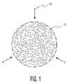
前記第1の技術は、核融合プラズマの電子増強に関して、小規模な熱核反応の微調整を提供する有用な手段である。それは電子温度に対するイオン温度の調整を可能にするものであり、したがって前記反応の燃焼特性を変える。電子増強は、プラズマの縮退の状態が先に発明の背景において定義されている「縮退」にあっても有用である。しかし、電子増強の必要レベルはプラズマの縮退の程度に伴って変化する。図1は、核融合燃料プラズマ(以下「プラズマ」)12中に注入されている電子群10を示す。核融合炉の構造に電子増強機構を与えることにより、異なる縮退の型での操作を経済的に行うことができる。イオン温度と電子温度との間に臨界的な平衡があることは前記従来の技術において教示されている。正確な温度(KeV)での電子増強(注入)により、核融合燃料を燃焼させるための最適な条件をより容易に得ることができる。このプロセスは、さらに、選択された量の高亜鉛材料での前記燃料の制御された不純物添加すなわちドーピングにより微調整することができる。1 Active control of ion-to-electron temperature ratio The first technique is a useful means for providing fine tuning of a small scale thermonuclear reaction in terms of electron enhancement of a fusion plasma. It allows adjustment of the ion temperature relative to the electron temperature and thus changes the combustion characteristics of the reaction. Electron enhancement is useful even when the degenerative state of the plasma is in “degeneration” as previously defined in the background of the invention. However, the required level of electron enhancement varies with the degree of plasma degeneracy. FIG. 1 shows a group of
図2は、電子群10を放射する陰極16を含む好ましい電子銃14を示す。電子群10は、一連の電極18,20及び22により加速され、開口24を通してプラズマ12(図1)に向けられる。電子銃14は、非磁性で真空気密構造のハウジング26内に据えられている。陰極16は陰極支持体28に据え付けられており、陰極支持体28は、真空気密の、また電気的に絶縁されたフィードスルー30を介して、囲い26の後壁を貫通している。陰極支持体28の左端部がフィードスルー30から姿を現しており、これは電力を受け取るための電気的接続点として働く。グリッド18と加速器電極20及び22とは、電子群10のビームを制御しかつ抜き出し、またこれをプラズマ12に集束する働きをなす。真空気密の、また電気的に絶縁されたフィードスルー32,34及び36は、それぞれ、グリッド18と加速器電極20及び22とを機械的に支持しまたこれらへの電気的接続を与える。化学的ゲッター・ポンプ38はハウジング26内を真空に保つのに役立つ。真空気密の、また電気的に絶縁されたフィードスルー40は、ゲッター・ポンプ38を支持しまたこれへの電気的接続を与える。 FIG. 2 shows a
前述した従来技術は、電子増強が縮退の任意の状態(すなわち、縮退、非縮退又は部分的縮退)にあるプラズマに望ましいことであるとする一方、縮退プラズマを伴う実施により最大の効果を得ることができることを教示する。 While the prior art described above states that electron enhancement is desirable for plasmas in any state of degeneration (ie, degenerate, non-degenerate or partially degenerate), the maximum effect can be obtained by implementation with degenerate plasma. Teaching that you can.
核融合燃料の燃焼に起因するプラズマ中のイオン群と電子群との間の温度差が非常に大きいと、エネルギが前記イオン群から前記電子群へと流れ込み、前記反応を抑制する可能性があることは、先に発明の背景に記載したように、サン等によって示されてきている。本発明によれば、前記複数の電子供給源が、ターゲットとされる燃料プラズマに高エネルギ電子群を充満させる。個々の燃料ペレットの軌跡にわずかな逸脱が許されるように、前記ターゲットの燃料プラズマだけでなく該ターゲット燃料の境界を越える追加の体積をも充満させることが好ましい。ここにおいて、前記追加の体積は、例えば、前記ターゲットの燃料プラズマの幾何学的中心を経て伸びる線に沿って測定される、前記ターゲットの燃料プラズマの最大寸法の1パーセントをあらわす。前記電子群のエネルギレベルは、所望温度での電子群の注入により前記ターゲット燃料のプラズマ中で正確な電子温度を得るように調整することができる。これは、前記複数の電子供給源に取り付けられた電力供給源の電圧を変化させることによりなされる。前記電子群の軌道は、後述するように、図4に示す加速器電極20及び22のような電磁又は静電の集束手段のいずれかにより制御される。 If the temperature difference between the ion group and the electron group in the plasma due to the combustion of the fusion fuel is very large, energy may flow from the ion group to the electron group and suppress the reaction. This has been shown by Sun et al. As previously described in the background of the invention. According to the present invention, the plurality of electron supply sources fill the target fuel plasma with the high energy electron group. It is preferable to fill not only the target fuel plasma but also an additional volume beyond the target fuel boundary so that a slight deviation in the trajectory of the individual fuel pellets is allowed. Here, the additional volume represents, for example, 1 percent of the maximum dimension of the target fuel plasma, measured along a line extending through the geometric center of the target fuel plasma. The energy level of the electron group can be adjusted to obtain an accurate electron temperature in the target fuel plasma by injection of the electron group at a desired temperature. This is done by changing the voltage of the power supply source attached to the plurality of electron supply sources. As will be described later, the trajectory of the electron group is controlled by either electromagnetic or electrostatic focusing means such as
前記エネルギ駆動手段から前記電子群を分離して導入する必要がある。その手配には、高周波加熱機能の危険にさらすことなしに前記反応の特別な要件に適合するように前記電子エネルギを微調整することが可能であるという有利性があり、これは、2008年3月13日付け米国特許出願公報US 2008/0063132 A1において本発明者シー エー バーンバックにより開示されている。この公報は、以下において、「'132公報」として言及されている。図3は、中心の球形の真空容器44を含む好ましい核融合炉42を示す。複数のX線レーザ46と複数の電子銃14とが、容器44の中心の周りに、容器44の表面上に対称に配置されている。真空容器44に接続された燃料ペレット注入器48が示されている。 It is necessary to introduce the electron group separately from the energy driving means. The arrangement has the advantage that the electronic energy can be fine-tuned to meet the special requirements of the reaction without risking the high-frequency heating function, which is U.S. Patent Application Publication No. US 2008/0063132 A1 dated May 13, disclosed by the inventor CA Burnback. This publication is referred to below as the “'132 Publication”. FIG. 3 shows a preferred fusion reactor 42 that includes a central
前記核融合燃料を適切に照射するため、複数の電子銃14が好ましくは前記プラズマの周りに対称に4πステラジアンにわたって配置され、またプラズマ12(図1)上に焦点が合わされている。電子群10(図1)の複数のビームの焦点合わせすなわち集束は図4に示すように行うことができる。この図では、電極20及び22(図2にも示されている)が電子群10の前記ビームをプラズマ12の質量中心に集束させている。グリッド18は、開口24への前記電子群の流れを制御しかつ調整し、また前記パルス群のタイミングの同期を可能にする。好ましくは、全ての電子供給源は同一のエネルギ(電子ボルト[eV])及びフルエンス(アンペア)を有する。全ての電子源が所望のエネルギ及びフルエンスを有することを確実なものとするため、図5に示すような電子銃コントローラ50が設けられている。電子銃コントローラ50は、ユーザ制御の電圧入力54とユーザ制御の電流入力56とを有する高圧電源52を備える。ユーザ制御入力54及び56は、使用に供されるであろう種々の制御入力の一つである。システムのレベル制御を与えるためにホストコンピュータ58が電子銃コントローラ50に接続されている。高圧電源52は、ホストコンピュータ58の制御下において、電子銃14のための全ての必要な電圧と制御信号とを供給する。 In order to properly irradiate the fusion fuel, a plurality of
1つの可能な例として、前記核融合燃料ターゲットの周りに対称に置かれる複数の例えば6つの直角に配置された電子供給源が所望の均等度を得るために使用され、各電子供給源は前記核融合燃料ターゲットの表面積の約1/6を照射する。電子供給源のその他の数は本明細書に基づきこの技術分野の当業者に明らかであろう。前記複数の電子供給源は、これらが、ここに説明したエネルギ、量又はフルエンス、並びに同期させるための能力の条件に適合する限りどのようなタイプの電子銃をも含む。 As one possible example, a plurality of, for example, six orthogonally arranged electron sources placed symmetrically around the fusion fuel target are used to obtain the desired uniformity, each electron source being said Irradiate about 1/6 of the surface area of the fusion fuel target. Other numbers of electron sources will be apparent to those skilled in the art based on this specification. The plurality of electron sources includes any type of electron gun as long as they meet the energy, quantity or fluence described herein and the ability to synchronize.
前記複数の電子供給源は、使用される核融合燃料に固有の予め定められたエネルギの予め定められた数の電子群で前記ターゲットの核融合燃料プラズマ領域を充満させることが望ましい。グリッド18は電子量の同期及び制御を行うことができる。結果として生じる電子群の合流により、電子群に対するイオン群の所望比率を得るために、存在するイオンの数に対する正確な電子の数を提供するという目的が果たされる。前記イオン温度は、前記核融合燃料の組成とポンピング用X線ビーム群のエネルギとから決定することができる。前記イオン温度から、電子温度に対するイオン温度の所望の比率を得るために前記電子供給源電源に必要とされる電圧の設定を決定することができる。前記電子量は、グリッド18の働きによって調整されるように、供給される前記核融合燃料における原子数により決定される。 Preferably, the plurality of electron sources fills the target fusion fuel plasma region with a predetermined number of electrons of a predetermined energy specific to the fusion fuel used. The
サン等は、制動放射損失を回避するために電子温度(Te)がイオン温度(Ti)よりも十分に低くなければならないと教示する。電子温度Teは、核融合の副産物が前記イオン群によって優先的に停止されるため、あまりに低くすることができない。このことを考慮すると、前記電子温度は、自己燃焼の可能性を維持するために狭い範囲内になければならない。電子温度Teは、前記イオン群からのエネルギ入力と前記制動放射からの損失との間のバランスにより決定される。Teに対するTiの比率は、使用される前記核融合燃料によって変化する。例えば、重水素(デュートリウム)‐重水素、重水素‐三重水素(トリチウム)、重水素‐3ヘリウム、陽子‐6リチウム、陽子‐11ホウ素のような典型的核融合燃料では、前記比率は通常2:1と20:1との間で異なる。Sun et al. Teach that the electron temperature (Te) must be sufficiently lower than the ion temperature (Ti) to avoid bremsstrahlung loss. The electron temperature Te cannot be made too low because fusion byproducts are preferentially stopped by the ions. Considering this, the electron temperature must be within a narrow range in order to maintain the possibility of self-combustion. The electron temperature Te is determined by the balance between the energy input from the group of ions and the loss from the bremsstrahlung. The ratio of Ti to Te varies with the fusion fuel used. For typical fusion fuels such as deuterium (deuterium) -deuterium, deuterium-tritium (tritium), deuterium-3 helium, proton-6 lithium, proton-11 boron, the ratio is usually Different between 2: 1 and 20: 1.
好ましくは、複数の電子供給源は予め定められたエネルギ、及びフルエンス又は量の電子ビームを供給し、またこれらは前記核融合燃料プラズマに向けられ、該プラズマを照射する。好ましくは、前記複数の電子供給源がこれらの電子ビームが前記核融合燃料ターゲットプラズマの周りに対称に向けられるように配置されると仮定すると、全ての電子供給源が互いに10分の1パーセント以内の電圧を個々に有し、また、互いに4分の1パーセント以内の電流を個々に有する。好ましくは、使用される電子供給源の数は、前記プラズマ内の他の任意の単位体積の10パーセント以内である前記核融合燃料プラズマの単位体積当たりの電子の指定数になる。 Preferably, the plurality of electron sources provide a predetermined energy and fluence or quantity of electron beams, which are directed at and irradiate the fusion fuel plasma. Preferably, assuming that the plurality of electron sources are arranged such that their electron beams are directed symmetrically around the fusion fuel target plasma, all electron sources are within 1/10 percent of each other. And have currents within a quarter percent of each other. Preferably, the number of electron sources used will be the specified number of electrons per unit volume of the fusion fuel plasma that is within 10 percent of any other unit volume in the plasma.
先に定義した必要とされる条件を達成するであろう、多数の想定し得る電子供給源の形態及びターゲット核融合材料の周りの前記電子供給源の方向がある。 There are a number of possible electron source configurations and directions of the electron source around the target fusion material that will achieve the required conditions defined above.
前述したところでは、前記核融合プラズマの縮退の程度に対する制御された核融合反応の能動的最適化が開示されている。これは、電子温度(Te)に対するイオン温度(Ti)の比率を変えるための前記電子温度と、反応中における指定電子量の選択的導入とを変化させることにより達成される。これらの変更により、プラズマの種々の縮退、部分的縮退及び非縮退の状態における操作に関して核融合反応の過早点火条件の改善の最適化を図ることができる。 In the foregoing, active optimization of the controlled fusion reaction with respect to the degree of degeneration of the fusion plasma is disclosed. This is achieved by changing the electron temperature for changing the ratio of the ion temperature (Ti) to the electron temperature (Te) and the selective introduction of the specified amount of electrons during the reaction. With these changes, it is possible to optimize the improvement of the pre-ignition conditions of the fusion reaction with respect to operation in various degenerate, partially degenerate and non-degenerate states of the plasma.
前述した電子増強プロセスの形態は、図6に示すような典型的な磁気閉じ込めに適用することができる。複数の電子銃14が円環面形状の真空室62の周りに対称に配置されている。前記円環面の水平面に関連して、等間隔をおかれた複数の放射方向位置のそれぞれに、3つの電子銃14が120°の角度的間隔で前記水平面に対して垂直に配置されている。典型的には、磁気閉じ込め核融合炉は多数組の直角に配置されたポロイダル磁石64及びトロイダル磁石66を備える。これらの磁石64及び66は、真空炉62内に核融合プラズマ12(図1)を含む磁気閉じ込め領域を生じさせるために使用される。これらの電子銃14は、電子銃コントローラ50(図5)により制御されて、所望の電圧及びフルエンスの電子群10(図1)を前記プラズマに充満させる。 The form of the electron enhancement process described above can be applied to a typical magnetic confinement as shown in FIG. A plurality of
2 核融合反応の時間的に段階分けされたポンピング
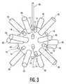
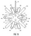
核融合反応の時間的に段階分けされたポンピングに関する第2の技術は、前記'132公報に記載されたシステムで使用することができる。また、前記時間的に段階分けされたポンピングの原理は他の慣性閉じ込め核融合システムに適用可能である。前記'132公報においては、前記反応炉が複数のX線レーザ・ドライバを有する。前記'132公報の図面は6つの対称に配置されたドライバを示すのみであるが、本文ではもっと多くの数を考慮しており、ドライバの次の理論的な数は、時間的にポンピングが行われる核融合反応炉70として図7に示されているように、14である。本発明のこの実施形態は、前記核融合反応を駆動するための時間的に段階分けされたパルス列を採用する。第1の組の複数のX線レーザ46a(前記'132公報に示されているように3つ垂直軸上に配置された6つのレーザ)が最初に点火する。第2の組46b(残りの8つ)が、短い予め定められた時間的間隔の後に点火する。図示を明瞭にするため、第2の組46bが第1の組46aより太い線で示されている。2 Time-stepped pumping of the fusion reaction The second technique for time-stepped pumping of the fusion reaction can be used in the system described in the '132 publication. Also, the time-staged pumping principle can be applied to other inertial confinement fusion systems. In the '132 publication, the reactor has a plurality of X-ray laser drivers. The drawing of the '132 publication only shows six symmetrically arranged drivers, but the text considers a larger number, and the next theoretical number of drivers is pumped in time. 14 as shown in FIG. This embodiment of the present invention employs a time-stepped pulse train to drive the fusion reaction. A first set of
パルス群の複数の組間の時間的間隔は臨界値である。もしも第2のパルスの組があまり早くに到達すると、第1のパルスの組と合わさり、流体力学的不安定性を修正する機会がない。同時の全てのパルス組(パルス群間の遅れがゼロ)により前記反応炉の運転を行うことができる。これは前記'132公報により考慮された条件である。対照的に、本発明の実施形態は、前記パルス群を時間内に僅かに隔てられた対称的な複数組に時間的に隔てることを可能にする調整可能システムを企図する。間隔があまり大きいと、前記第2のパルスは、前記反応が(1)崩壊した後、(2)不安定性を後に修正すること不可能である「帰還不能点」を通過した後、又は(3)全核融合反応が起こり、前記第2のパルスが不要であるか若しくは弊害をもたらす後に到達する。 The time interval between multiple sets of pulse groups is a critical value. If the second set of pulses arrives too early, there is no opportunity to combine with the first set of pulses and correct the hydrodynamic instability. The reactor can be operated by all simultaneous pulse sets (the delay between pulse groups is zero). This is a condition considered in the '132 publication. In contrast, embodiments of the present invention contemplate an adjustable system that allows the groups of pulses to be separated in time into symmetrical sets that are slightly separated in time. If the interval is too large, the second pulse will either after the reaction (1) decays, (2) after passing through a “no return point” where it is impossible to correct the instability later, or (3 ) A total fusion reaction takes place and arrives after the second pulse is unnecessary or harmful.
前記したタイミングの問題を数値化するため、前記熱核融合が起こる時間までに前記第1の対称的X線圧縮パルス組が前記燃料ペレットに最初に当たる時間によって前記反応の全時間が定められる。もし、例えば、前記反応の全時間が3ナノ秒であるとすると、前記第2のパルス組は、例えば、前記第1のパルス組の後約500ピコ秒で到達する。もし、前記第2のパルス組が前記第1のパルス組の後に約1.5ナノ秒以上で到達するときは、それは遅すぎる。もし、それが前記第1のパルスの後に10ナノ秒で到達するときは、それは利用するには明らかに遅すぎる。ここで与えられる値は相対的なものであり、また単に原理を表わすように企図されたものであって、核融合反応を行うための現実の値を規定するものではない。 To quantify the timing problem described above, the total time of the reaction is determined by the time that the first symmetric X-ray compression pulse set first strikes the fuel pellet by the time that the thermonuclear fusion occurs. If, for example, the total time of the reaction is 3 nanoseconds, the second pulse set will arrive, for example, about 500 picoseconds after the first pulse set. If the second pulse set arrives after about 1.5 nanoseconds after the first pulse set, it is too late. If it arrives 10 nanoseconds after the first pulse, it is clearly too late to utilize. The values given here are relative and are merely intended to represent the principle and do not prescribe actual values for performing a fusion reaction.
図8A‐8Dは、核融合反応のための過早点火条件を確立するためのエネルギの時間的に段階分けされたパルス群の相対的時系列を示す。 8A-8D show the relative time series of time-staged pulses of energy to establish pre-ignition conditions for the fusion reaction.
図8A:この図は、第1のX線パルス72と、第2のX線パルス74とを示す。両矢印75は第2のパルス74が可変の時間的間隔中に生じ得ることを示す。 FIG. 8A: This figure shows a
図8B:この図は、第1のX線パルス72及び第2のX線パルス74と、定められた時間的間隔後に第1のX線パルス72に続く高周波加熱パルス76とを示す。両矢印75は第2のパルス74が可変の時間的間隔中に生じ得ることを示す。 FIG. 8B: This figure shows a
図8C:この図は、電子パルス78及び第2のX線パルス74が後に続く第1のX線パルス72を示す。両矢印75は第2のパルス74が可変の時間的間隔中に生じ得ることを示す。両矢印79は、前記タイミング及び同期の調整を可能にするために電子パルス78が可変の時間的間隔中に生じ得ることを示す。 FIG. 8C: This figure shows a
図8D:この図は、電子パルス78が後に続く第1のX線パルス72を示す。両矢印79は、電子パルス78が可変の時間的間隔中に生じ得ることを示す。 FIG. 8D: This figure shows a
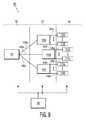
先の説明は、関わりのある平衡感覚を与える、種々のパルスの組み合わせ間の相対関係を教示する。この記述は、2以上の組に分かれ得る複数の駆動信号を供給することができることが望ましいことを示す。これは、図8A‐8D(また、後述の図11A‐11B)の両矢印75及び79により示された可変のタイミングが細かい(例えば、ピコ秒以下)分解でより正確に調整され得る点で有利である。図9に示すように、これは、カリフォルニア州 サンフランシスコのハイランド テクノロジー社(Highland Technologies Inc.)により製造されているような市販のタイミング遅延発生器を使用するタイミング・ネットワーク90を創出することにより達成することができる。タイミング・ネットワーク90は3つのセクション、すなわちクロックセクション92と、タイミングセクション94と、ケーブル及びジッタ補償セクション96とを含む。クロックセクション92は、高精度低ジッタ・オシレータのようなマスタークロック98を含む。前記マスタークロックは、全システムのためのタイミングパルス群を発する。マスタークロック98は典型的には温度制御された水晶振動子からなるが、原子時計とすることもできる。これは、好ましくは同長のケーブル100a、100b及び100cのアレイによりタイミングセクション94に接続される。これらのケーブルの長さは、好ましくは、コネクタを含めて、全体に0.001インチ(25.4ミクロン)に規制される。 The above description teaches the relative relationships between the various pulse combinations that give a relevant sense of balance. This description indicates that it is desirable to be able to provide a plurality of drive signals that can be divided into two or more sets. This is advantageous in that the variable timing indicated by the
タイミングセクション94は、3つのタイミング遅延発生器102a、102b及び102cを含む。タイミング遅延発生器102aは前記第1のX線パルスの点弧又は発火時間を確立する。タイミング遅延発生器102bは、前記システムに存在する場合、前記電子パルスの点弧又は発火時間を確立する。電子パルス群のタイミングは、図8cに符号79で示されているように、システム・オペレータにより予め定められる。タイミング遅延発生器102cは、図8A‐8C及び後述する図11Aに示すように、前記第1のX線パルスに対する前記第2のX線パルスの遅れを確立する。電子群10の流れ及び量は、ホストコンピュータ58の制御下においてグリッド18(図2)の制御により調整される。 Timing
セクション94のタイミング遅延発生器は、セクション96のケーブル及びジッタ補償遅延発生器のアレイに接続されている。ここで用いられるようなケーブル補償は、パルス群が第1の組46aのX線レーザ群、複数の電子銃14、又は第2の組46bのX線レーザ群に同調して到達することを確実にすべく、ケーブル104a‐104f、106a‐106n(nは使用される電子銃14の数である。)及び108a‐108hを補正するための手段を提供する。ここで用いられるようなジッタ補償は、レーザ46(図3)、又は組46a及び46b(図10)のレーザ若しくは電子銃14(図2、3及び10)の製造時の小さい差を補正するための手段を提供する。各装置はそれ自体のジッタ(jitter value)を有し、それは時間と共に変化せず、また、ケーブル長さの補償のためのオフセットと同様に取り扱われる。 The
使用の際、最初にケーブル補償のための遅延及びジッタセクション96の遅延が設定される。次に、図8A‐8D及び11A‐11Bに示されているような所望の操作順序を提供するためにタイミングセクション94のタイミング調整が設定される。それぞれがホストコンピュータ58に接続されている、タイミング遅延発生器102a‐102c、110a‐110f、112a‐112n(nは使用される電子銃14の数である。)及び114a‐114h並びにマスタークロック98が、ホストコンピュータ58により制御される。これは、前記システムの始動の間の一連の繰り返しの測定により前記タイミング条件の迅速な最適化を可能にする。 In use, the cable compensation delay and
前記システム構造はタイミング・ネットワーク90と電子銃コントローラ50とに対する多入力手段を確保し、それは、オペレータによる直接の手動制御入力又はホストコンピュータ58によるプログラム制御された入力を含み得る。 The system structure provides multiple input means for the timing network 90 and the
a 流体力学的不安定性
都合のよいことに、核融合の時間的に段階分けされたポンピング技術は、前記燃料ペレットの製造精度の低減を可能にすることが期待される。現在では、前記プラズマの本体から外側へ波打ちまた前記プラズマを局部的に冷却するプラズマの「噴流群」の形成を低減するため、表面の不連続群を全表面の1パーセント未満にまで制限する必要がある。このようなプラズマの「噴流群」は流体力学的不安定性の特徴である。本発明のこの実施形態の図8A‐8C及び図11A(もし採用されるときは、追加の時間的に段階分けされた1又は複数のパルス)に示す第2番目の時間的に段階分けされたX線パルス74は、前記流体力学的不安定性の噴流群の特徴をそれらが形成するときに含むように振る舞う。したがって、燃料ペレットのより多くの表面不連続群が許容され得る。a Hydrodynamic instability Conveniently, the time-sequential pumping technique of fusion is expected to allow a reduction in the production accuracy of the fuel pellets. Currently, it is necessary to limit the surface discontinuities to less than 1 percent of the total surface to reduce the formation of plasma "jets" that undulate from the body of the plasma and locally cool the plasma. There is. Such “jet groups” of plasma are characteristic of hydrodynamic instabilities. The second temporally staged shown in FIGS. 8A-8C and FIG. 11A (if employed, one or more additional staged pulses) of this embodiment of the present invention.
各組のレーザが核融合を得るために必要な全駆動エネルギを供給することができるであろうことはこの技術分野の当業者には明らかであろう。これは完全には必要でないが、各組のみが必要なエネルギの一部を有する場合、この条件においては両パルスが特定の時間ウインドウ内に到達しなければならないため、これが前記システムのタイミング公差にさらなる制限を置く。本発明のこの実施形態の目的は、流体力学的不安定性に対する全核融合反応の感度を低減することにあり、したがって全駆動エネルギ容量をもつ各組の対称パルス群を提供することが望ましくまた好ましい。 It will be apparent to those skilled in the art that each set of lasers will be able to provide the total drive energy required to obtain fusion. This is not completely necessary, but if only each set has a fraction of the energy required, this will cause this system timing tolerance because both pulses must reach within a certain time window under this condition. Put additional restrictions. The purpose of this embodiment of the present invention is to reduce the sensitivity of the total fusion reaction to hydrodynamic instability, and it is therefore desirable and preferred to provide each set of symmetrical pulses with full driving energy capacity. .
3以上の時間的に段階分けされた組の駆動パルス群が流体的不安定性の効果を軽減するために必要とされ、また前記システム構成がこれを提供し得ると見込まれる。慣性閉じ込め核融合反応における負の効果すなわち流体力学的不安定性を有利に低減する役割を果たすこの技術の多数の考え得るバリエーションがあることは、本明細書からこの技術分野の当業者には明らかであろう。 More than two temporally graded sets of drive pulses are required to mitigate the effects of fluid instability and it is anticipated that the system configuration can provide this. It will be apparent to those skilled in the art from this specification that there are many possible variations of this technique that serve to advantageously reduce the negative effects, ie hydrodynamic instabilities, in inertial confinement fusion reactions. I will.
3 2つの技術の相乗的組み合わせ
図11Aに示すように、2つの前述した技術を組み合わせることにより最大の有用性及び相乗効果が得られる。それぞれの個々のプロセスはそれ自体に固有の特性を有するが、組み合わされると、相乗的手法が現れる。組み合わされたプロセスは、図11Aを参照すると、核融合反応を引き起こし、これを制御するための手段として次の一連の事象を与える。3 Synergistic combination of the two technologies As shown in FIG. 11A, the combination of the two aforementioned technologies provides maximum utility and synergy. Each individual process has its own unique characteristics, but when combined, a synergistic approach appears. The combined process, referring to FIG. 11A, causes a fusion reaction and gives the following sequence of events as a means to control it.
1. 第1のX線パルス72は前記核融合燃料を照射する。これが、プラズマ12(図1)を生じさせる、前記燃料の全電離を起こさせ、前記圧縮及び加熱のプロセスを開始させる。前記'132公報に開示されているように、高周波加熱パルス76を選択的に、第1のX線パルス72が当てられた後の定められた時間に核融合燃料プラズマ12に当てることができる。 1. The
2. 電子パルス78は前記核融合燃料領域を照らし、前述したステップ1により生成されたプラズマ12(図1)中に特定エネルギの特定数の電子10(図1)を導入する。これは、電子温度に対するイオン温度の割合を変化させて前記したような悪影響を最小限にし、これにより望ましい反応が生じる可能性を増大させる効果をもつ。電子群10の流れ及び量は、ホストコンピュータ58の制御下におけるグリッド18(図2)の制御により調整される。 2. The
3. 第2のX線パルス74はプラズマ12(図1)をさらに圧縮しまた加熱する。この第2のX線パルス74は、第1のX線パルス72を形成するビーム群とは異なる方向から到達するビーム群からなる。これの効果は、先行のステップの間に形成される任意の流体的不安定性を抑制しかつ軽減することである。 3. The
4. これらの3つの組のパルス群(72+76、78、及び74)のタイミング及び順序は重要であり、最良のシステム性能を得るために注意深く調整されなければならない。これは、各組のパルス群の生成のタイミングを制御するための遅延発生器102b(図9)を調整することにより行われる。電子パルス78のタイミングは両矢印79で示すように調整され、また、第2のX線パルス74は両矢印75で示すように調整される。システム性能を最適化するための最も簡単な方法は、ホストコンピュータ58(図9)の制御下でタイミング・ネットワーク90に1又は複数の制御された入力を与える反復最適化ルーティンを用いることである。この最適化ルーティンのプログラミングは、本明細書に基づいてこの技術分野の当業者には明らかであろう。この最適化ルーティンは、後述するように、図8A‐8D及び図11A‐11Bの個々の遅延設定の組み合わせ75及び79の試験を行い、また、前記最良のシステム性能を生じさせる前記遅延設定の組み合わせを決定することができる。制御された入力を与えるためのこのようなコンピュータ・ルーティンの使用は、図5に示す54及び56、並びに、図8A‐8Dと図11A‐11Bとに示す75及び79のようなユーザ制御の入力の採用にとって好ましい。 4). The timing and order of these three sets of pulses (72 + 76, 78, and 74) is important and must be carefully adjusted to obtain the best system performance. This is done by adjusting the delay generator 102b (FIG. 9) for controlling the timing of generation of each set of pulse groups. The timing of the
図11Aに示す前記ステップの順序のバリエーションが図8A‐8Dに示され、前述したように、図11Bに示されている。 Variations of the order of the steps shown in FIG. 11A are shown in FIGS. 8A-8D and, as described above, shown in FIG. 11B.
図11Bは高周波加熱パルス76が続く第1のX線パルス72を示し、前記高周波加熱パルスは定められた時間的間隔の後に第1のX線パルス72に続き、その後に電子パルス78が続く。両矢印79は、電子パルス78が可変の時間的間隔中に生じ得ることを示す。 FIG. 11B shows a
本明細書に記載の全ての増強は、熱核融合反応の過早点火条件の改善された制御を達成すべく、前記'132公報の技術と組み合わせることができる。 All enhancements described herein can be combined with the technology of the '132 publication to achieve improved control of pre-ignition conditions for thermonuclear reactions.
好ましい実施形態
先に議論した技術は、単独で又は組み合わせて、数多くの異なるタイプの核融合プロセスに適用可能であるが、これらは元々前記'132公報に記載の発明に対して補助的なものとして着想された。そのようなものとして、これらは特に好ましい技術であり、本発明の図面を参照して以下の通りにより詳細に記載されている。Preferred Embodiments The techniques discussed above, alone or in combination, can be applied to many different types of fusion processes, but these are originally ancillary to the invention described in the '132 publication. Inspired. As such, these are particularly preferred techniques and are described in more detail as follows with reference to the drawings of the present invention.
前記'132公報は、核融合反応のいくつかの過早点火条件を制御するための独特のシステムを記載している。それは、直接X線駆動の慣性閉じ込め核融合システムとして分類される。これは、前記反応の最初のポンピング手段としてX線レーザ群46(図3)を利用する。本発明は、核融合反応の過早点火条件を制御するための能力をさらに発展させるシステムレベルの増強を記述する。 The '132 publication describes a unique system for controlling several pre-ignition conditions of a fusion reaction. It is classified as a direct X-ray driven inertial confinement fusion system. This utilizes an X-ray laser group 46 (FIG. 3) as the first pumping means of the reaction. The present invention describes a system level enhancement that further develops the ability to control pre-ignition conditions for fusion reactions.
前記'132公報のシステムは、核融合ターゲット材料を受け入れるための中心ターゲット室44(図3)を含む。核融合プラズマ12(図1)及び熱の形態でエネルギを放出する、前記材料の制御された核融合反応を開始するために前記室内の核融合ターゲット材料にエネルギを供給するために複数のX線レーザ46(図3)がターゲット室44の周りに配置されている。 The '132 publication system includes a central target chamber 44 (FIG. 3) for receiving a fusion target material. A plurality of x-rays for supplying energy to the fusion target material in the chamber to initiate a controlled fusion reaction of the material, releasing energy in the form of a fusion plasma 12 (FIG. 1) and heat. A laser 46 (FIG. 3) is disposed around the
より詳細には、図3が、制御された核融合によりエネルギを発生するための反応炉を示す。前記システムは、中心ターゲット室44を含む。一連の6以上のX線レーザ46が中心ターゲット室44の周りに対称的な対をなして配置されている。対称的なX線レーザ群46は、室44の中心で前記ターゲット核融合ペレット(図示せず)に衝突する好ましくは球状に近い波面を集合的に生成するために、室44の中心のターゲットペレット位置の周りに対称の態様で配置されている。X線レーザ群46は、好ましくは、米国特許第4,723,263号明細書にこの発明の発明者により最初に記載された誘導X線放出体(SXE)群である。好ましい実施形態においては、前記したSXE X線レーザ群46に、前記反応に追加の熱を提供するための高周波エネルギ76(図8B、11A及び11B)の同時パルスを供給する高周波生成手段(図示せず)が取り付けられている。これは、さらに、前記'132公報の図10‐13の議論中に記載されている。 More particularly, FIG. 3 shows a reactor for generating energy by controlled fusion. The system includes a
任意の核融合システムの最適な性能は、前記燃料ターゲットペレットの完全対称圧縮の創出に依存する。本発明のX線レーザ群46(図3)は、前記ターゲットを対称に照射する手段を提供する。前記ターゲットに当たる前記波面(図示せず)がその半径が前記ターゲットペレットの半径に一致する凹形の幾何学的形状を与えられときは、前記燃料ターゲットペレット上にほとんど完全に対称の圧縮波面を創出することができる。これが必要である理由は、もし深刻であれば、非均一な態様で前記燃料ペレットを加熱させ、核融合反応において点火させないことがある流体的不安定性を最小限にすることである。本発明の特徴は、流体的不安定性の悪影響をさらに最小限に抑えるために時間的に段階分けされた方法で前記波面の凹形の幾何学的形状を有効活用することにある。これは、第1のX線パルス72(図8A‐8C及び図11A)に対してわずかに遅れた時間内に第2のX線パルス74を使用することにより行われる。組み合わされたエネルギビーム群の時間的に段階分けをされた波面72及び74は、2つの崩壊する球状シェルに近い。 The optimal performance of any fusion system depends on the creation of fully symmetrical compression of the fuel target pellet. The X-ray laser group 46 (FIG. 3) of the present invention provides means for irradiating the target symmetrically. When the wavefront (not shown) impinging on the target is given a concave geometry whose radius matches the radius of the target pellet, it creates an almost perfectly symmetrical compression wavefront on the fuel target pellet. can do. The reason for this is that if severe, the fuel pellets are heated in a non-uniform manner to minimize fluid instabilities that may not be ignited in a fusion reaction. A feature of the present invention is to effectively utilize the concave geometry of the wavefront in a time-stepped manner to further minimize the adverse effects of fluid instability. This is done by using the
典型的な直接駆動のICFターゲットの爆縮プロセスは、おおよそ3つの段階すなわち(1)最初の段階、(2)加速段階、及び(3)減速段階に分けられる。 The typical direct drive ICF target implosion process is roughly divided into three phases: (1) an initial phase, (2) an acceleration phase, and (3) a deceleration phase.
最初の段階において、第1の衝撃波が燃料ペレット内を進行し、前記ペレットが前記衝撃波により主に加速される。前記最初の段階は、第2の要求である前記燃料の全電離を有する。これは、前記核融合燃料イオン群が後の段階で結合されることで容易性を増大させることにより前記核融合反応を促進する。これは、高エネルギの衝突X線群が電子群をその軌道外に抜け出させ、むき出しの原子核を残すことにより達成され、それは他の原子核群に対する核融合のために好ましい状態である。外方の(又は断熱の)シェルが前記第2の段階で内方に向けて小さくなりながら加速される。次に、前記減速段階で燃料が大きく圧縮される。前記最初の段階では、前記ターゲット表面上の摂動が、最初のターゲット表面粗さに加えて、レーザ照射不均一性のために最初の印により種をまかれる。主として前記第2の(加速)段階における流体的不安定性のために前記外表面上で成長した摂動は、次いで、前記内表面に送り込まれる。 In the first stage, a first shock wave travels in the fuel pellet, and the pellet is mainly accelerated by the shock wave. The first stage has a second requirement, total ionization of the fuel. This promotes the fusion reaction by increasing the ease with which the fusion fuel ions are combined at a later stage. This is achieved by the high energy collisional X-ray group causing the electron group to escape out of its orbit, leaving a bare nucleus, which is the preferred state for fusion to other nuclear groups. The outer (or heat insulating) shell is accelerated while decreasing inward in the second stage. Next, the fuel is greatly compressed in the deceleration stage. In the first stage, perturbations on the target surface are seeded with an initial mark due to laser irradiation non-uniformity in addition to the initial target surface roughness. Perturbations that have grown on the outer surface primarily due to fluid instability in the second (acceleration) stage are then fed into the inner surface.
本発明のこの実施形態においては、図8Cを参照すると、時間的に段階分けされたパルス群の使用は、好ましくは前記した3段階に順序付けられる。最初のX線パルス72は前記最初の段階で前記プロセスを開始させる。それは、前記加速段階の開始時に電子パルス78によってすぐに引き継がれることが望ましい。電子パルス78の同期はグリッド18(図2)の使用により行われる。第2のX線パルス74は、好ましくは、前記加速段階の早期部分の間に前記電子パルスの後にすぐに続く。この順序は、前記電子群が、第1のX線パルス72の最初の衝突によって生じたプラズマと最適な相互作用をすることを可能にする。この作用は、プラズマ12(図1)に、最適な圧縮及び最終的には核融合爆縮の準備をさせる。また、第2のX線パルス74は、前記最初の段階及び加速段階の間に起こるいかなる流体力学的不安定性をも最小限にするように作用する。 In this embodiment of the invention, referring to FIG. 8C, the use of temporally staged pulses is preferably ordered in the three stages described above. The
本発明の代わりの実施形態において、前記'132公報のシステムは高周波パルス76(図8B、11A及び11B)を生成するためにX線レーザ群46(図3)に不可欠の高周波加熱手段を含む。このことの1つの結果は、150GHzを超える特定の周波数で200メガジュールを超える高周波加熱パルス76が同調して生成され、X線パルス72と共に進行する。この高周波パルス76は、本質的に追加のコスト又はエネルギ消費なしにプラズマ12(図1)に熱を追加供給することにおいて有用である。これは、それが、SXE X線レーザ群46のX線生成プロセスの余分なエネルギを使って発生されるからである。この高周波パルス76は定められた時間的間隔までX線パルス72に僅かに遅れる。高周波パルス76を第1のX線パルス72の直後に生じさせることにより、高周波パルス76は事実上電子パルス78とほぼ同調して到達する。好ましくは、ホストコンピュータ58(図9)を介してのタイミング・ネットワーク90(図9)への制御された入力は、これらの事象のタイミングが微調整され、この効果(図11A)を最適にすることを可能にする。これは、図11Aに示すように、4つの部分からなるパルス列を生じさせ、前記核融合燃料を点火するための最適な条件を創出するための前記核融合燃料の過早点火条件についての制御の程度を増大させる。 In an alternative embodiment of the present invention, the '132 publication system includes high frequency heating means essential to the X-ray laser group 46 (FIG. 3) to generate high frequency pulses 76 (FIGS. 8B, 11A and 11B). One result of this is that a high
本明細書は、慣性閉じ込め核融合(ICF)システムのための6つの別々の増強シナリオ、すなわち1 時間的に段階分けされたX線パルス群(図8A)、2 組み合わされた、時間的に段階分けされたX線パルス群及び高周波増強プラズマ(図8B)、3 組み合わされた、時間的に段階分けされたX線パルス群及び電子増強プラズマ(図8C)、4 電子増強プラズマ(図8D)、5 高周波及び電子増強プラズマ(図11B)、6 好ましい実施形態である、組み合わされた、時間的に段階分けされたX線パルス群及び高周波及び電子増強プラズマ(図11A)を開示する。 This specification describes six separate augmentation scenarios for an inertial confinement fusion (ICF) system: a group of X-ray pulses stepped in time (FIG. 8A), two combined, stepped in time Divided X-ray pulse group and radio frequency enhanced plasma (FIG. 8B), 3 Combined temporally staged X-ray pulse group and electron enhanced plasma (FIG. 8C), 4 Electron enhanced plasma (FIG. 8D), 5 High-frequency and electron-enhanced plasma (FIG. 11B), 6 A preferred embodiment, a combined time-staged X-ray pulse group and high-frequency and electron-enhanced plasma (FIG. 11A) is disclosed.
個々に、各技術が利点を有する。種々の組み合わせにおいて、これらの組み合わせは、核融合反応の過早点火条件についての増強及び制御の程度を連続的に増大させる。 Individually, each technology has advantages. In various combinations, these combinations continuously increase the degree of enhancement and control over the pre-ignition conditions of the fusion reaction.
本発明が図を用いた特定の実施形態に関して説明されているが、この技術分野の当業者には数多くの修正及び変更が思い浮かぶであろう。これに関連して、ここで使用されている用語「手段」は、この用語「手段」と共に使用される動詞が通常の単数の時制又は複数の時制であるかを問わず、単数又は複数の手段を暗示する。第2のX線パルスを発生するための第2の組のX線供給源群はあるシステムには存在しない。したがって、添付の請求の範囲は、全てのこのような修正及び変更が本発明の範囲及び精神に含まれ、これらをカバーするように企図されている。
Although the present invention has been described with respect to particular embodiments using figures, many modifications and changes will occur to those skilled in the art. In this context, the term “means” as used herein is intended to mean one or more means, regardless of whether the verb used with the term “means” is the usual singular or plural tense. Is implied. There is no second set of x-ray sources in some systems for generating the second x-ray pulse. Accordingly, the appended claims are intended to cover and cover all such modifications and changes as fall within the scope and spirit of the invention.
Claims (11)
Translated fromJapanesea)球状の核融合燃料ペレットを受け入れるための中心ターゲット室を備え、
b)複数のエネルギドライバは前記核融合燃料ペレットの周囲に対対称に配置され、核融合燃料由来のプラズマを作り出すために光学レーザ光線、X線パルス群又はイオン群の第1のエネルギパルスが前記核融合燃料ペレットの周囲に3次元的対称であるように前記核融合燃料に向けて方向付けられ、
c)前記複数のエネルギドライバから分離され予め定められたエネルギ及び量の個々の電子ビーム群を、前記核融合燃料由来のプラズマに向けられ、また該プラズマを照射する複数の電子供給源を備え、
d)前記個々の電子ビーム群を前記核融合燃料由来のプラズマに収束させる、方法。A method for injecting a predetermined energy and quantity of electrons into a plasma from an inertial confinement fusion fuel comprising: a) a central target chamber for receiving a spherical fusion fuel pellet;
b) A plurality of energy drivers are arranged symmetrically around the fusion fuel pellet, and the first energy pulse of the optical laser beam, the X-ray pulse group or the ion group is used to produce a plasma derived from the fusion fuel. directed towards thefusion fuel as is three-dimensionally symmetric around a fusion fuel pellets,
c) a plurality of electron sources separated from the plurality of energy drivers and directed toa plasmaderived from the fusionfuel with a predetermined energy and quantity of individual electron beams;
d) A method of focusing the individual electron beam groups on the plasma derived from the fusion fuel.
Applications Claiming Priority (5)
| Application Number | Priority Date | Filing Date | Title |
|---|---|---|---|
| US19043508P | 2008-08-28 | 2008-08-28 | |
| US61/190,435 | 2008-08-28 | ||
| US21144909P | 2009-03-30 | 2009-03-30 | |
| US61/211,449 | 2009-03-30 | ||
| PCT/US2009/055448WO2010047880A2 (en) | 2008-08-28 | 2009-08-28 | System for enhancing preignition conditions of thermonuclear fusion reactions |
Related Child Applications (1)
| Application Number | Title | Priority Date | Filing Date |
|---|---|---|---|
| JP2014143157ADivisionJP5832600B2 (en) | 2008-08-28 | 2014-07-11 | Method for inertial compression of fusion fuel pellets with time-spaced x-ray pulses |
Publications (3)
| Publication Number | Publication Date |
|---|---|
| JP2012501455A JP2012501455A (en) | 2012-01-19 |
| JP2012501455A5 JP2012501455A5 (en) | 2012-09-13 |
| JP5580825B2true JP5580825B2 (en) | 2014-08-27 |
Family
ID=42117497
Family Applications (2)
| Application Number | Title | Priority Date | Filing Date |
|---|---|---|---|
| JP2011525259AExpired - Fee RelatedJP5580825B2 (en) | 2008-08-28 | 2009-08-28 | Method for injecting a predetermined energy and quantity of electrons into a plasma derived from an inertial confinement fusion fuel |
| JP2014143157AExpired - Fee RelatedJP5832600B2 (en) | 2008-08-28 | 2014-07-11 | Method for inertial compression of fusion fuel pellets with time-spaced x-ray pulses |
Family Applications After (1)
| Application Number | Title | Priority Date | Filing Date |
|---|---|---|---|
| JP2014143157AExpired - Fee RelatedJP5832600B2 (en) | 2008-08-28 | 2014-07-11 | Method for inertial compression of fusion fuel pellets with time-spaced x-ray pulses |
Country Status (13)
| Country | Link |
|---|---|
| US (2) | US8934599B2 (en) |
| EP (2) | EP3091538A1 (en) |
| JP (2) | JP5580825B2 (en) |
| KR (3) | KR101722226B1 (en) |
| CN (1) | CN102204413A (en) |
| AU (1) | AU2009308061B2 (en) |
| BR (1) | BRPI0912590A2 (en) |
| CA (2) | CA2733939C (en) |
| IL (3) | IL211340A0 (en) |
| MX (1) | MX2011001859A (en) |
| NZ (2) | NZ614346A (en) |
| RU (1) | RU2011111554A (en) |
| WO (1) | WO2010047880A2 (en) |
Families Citing this family (15)
| Publication number | Priority date | Publication date | Assignee | Title |
|---|---|---|---|---|
| CN102301832B (en) | 2009-02-04 | 2014-07-23 | 全面熔合有限公司 | Systems and methods for compressing plasma |
| US20150380113A1 (en) | 2014-06-27 | 2015-12-31 | Nonlinear Ion Dynamics Llc | Methods, devices and systems for fusion reactions |
| US10269458B2 (en) | 2010-08-05 | 2019-04-23 | Alpha Ring International, Ltd. | Reactor using electrical and magnetic fields |
| US8891719B2 (en) | 2009-07-29 | 2014-11-18 | General Fusion, Inc. | Systems and methods for plasma compression with recycling of projectiles |
| US10319480B2 (en) | 2010-08-05 | 2019-06-11 | Alpha Ring International, Ltd. | Fusion reactor using azimuthally accelerated plasma |
| US10515726B2 (en) | 2013-03-11 | 2019-12-24 | Alpha Ring International, Ltd. | Reducing the coulombic barrier to interacting reactants |
| US10274225B2 (en) | 2017-05-08 | 2019-04-30 | Alpha Ring International, Ltd. | Water heater |
| CN103632733B (en)* | 2013-11-01 | 2016-01-20 | 罗天勇 | A kind of method utilizing neutron heating plasma |
| CN105779050B (en) | 2015-01-08 | 2019-05-28 | 非线性离子动力有限责任公司 | Natural gas is converted to liquid using rotation/separation system in chemical reactor |
| CN106783485B (en)* | 2016-12-09 | 2019-05-10 | 中国科学院深圳先进技术研究院 | CT system and its cold cathode X-ray tube |
| CN106783488B (en)* | 2016-12-09 | 2019-05-10 | 中国科学院深圳先进技术研究院 | CT system and its cold cathode X-ray tube |
| US10170883B1 (en)* | 2017-12-21 | 2019-01-01 | Innoven Energy Llc | Method for direct compression of laser pulses with large temporal ratios |
| CN113096832B (en)* | 2021-03-19 | 2023-04-14 | 哈尔滨工业大学 | A multi-shot target library for inertial confinement fusion |
| US20230107844A1 (en)* | 2021-10-05 | 2023-04-06 | Daniel Prater | Magnetohydrodynamic helicity and laminar flow kinematic dynamo generators |
| CN120379124A (en)* | 2024-01-23 | 2025-07-25 | 陕西星环聚能科技有限公司 | Plasma generation system, nuclear fusion reaction system and method |
Family Cites Families (19)
| Publication number | Priority date | Publication date | Assignee | Title |
|---|---|---|---|---|
| US3489645A (en)* | 1967-03-10 | 1970-01-13 | Cornell Aeronautical Labor Inc | Method of creating a controlled nuclear fusion reaction |
| US4058486A (en) | 1972-12-29 | 1977-11-15 | Battelle Memorial Institute | Producing X-rays |
| US3969628A (en)* | 1974-04-04 | 1976-07-13 | The United States Of America As Represented By The Secretary Of The Army | Intense, energetic electron beam assisted X-ray generator |
| US4363775A (en)* | 1976-12-30 | 1982-12-14 | International Nuclear Energy Systems Co. | Controlled nuclear fusion apparatus |
| US4172008A (en)* | 1977-08-23 | 1979-10-23 | Dubble Whammy, Inc. | Nuclear fusion reactor |
| US4272319A (en)* | 1978-02-28 | 1981-06-09 | The United States Of America As Represented By The United States Department Of Energy | Device and method for electron beam heating of a high density plasma |
| US4440714A (en)* | 1981-01-29 | 1984-04-03 | The United States Of America As Represented By The United States Department Of Energy | Inertial confinement fusion method producing line source radiation fluence |
| US4723263A (en) | 1985-05-20 | 1988-02-02 | Quantum Diagnostics, Ltd. | X-ray source |
| US6870498B1 (en)* | 1987-05-28 | 2005-03-22 | Mbda Uk Limited | Generation of electromagnetic radiation |
| US5818891A (en)* | 1996-05-08 | 1998-10-06 | Rayburn; David C. | Electrostatic containment fusion generator |
| IL129608A0 (en)* | 1996-11-01 | 2000-02-29 | Miley George H | Plasma jet source using an inertial electrostatic confinement discharge plasma |
| US5825836A (en)* | 1997-02-19 | 1998-10-20 | Jarmusch; D. Lloyd | Tetrahedral colliding beam nuclear fusion |
| CA2325362A1 (en)* | 2000-11-08 | 2002-05-08 | Kirk Flippo | Method and apparatus for high-energy generation and for inducing nuclear reactions |
| EP1623481A4 (en) | 2003-03-21 | 2009-08-19 | Univ Utah State | SYSTEMS AND METHOD FOR PLASMA CONTROL |
| JP4081029B2 (en)* | 2004-02-26 | 2008-04-23 | 匡且 村上 | Fusion target and fusion ignition method |
| US7482607B2 (en) | 2006-02-28 | 2009-01-27 | Lawrenceville Plasma Physics, Inc. | Method and apparatus for producing x-rays, ion beams and nuclear fusion energy |
| US9036765B2 (en)* | 2006-05-30 | 2015-05-19 | Advanced Fusion Systems Llc | Method and system for inertial confinement fusion reactions |
| JP2009288229A (en)* | 2008-05-26 | 2009-12-10 | Motohiko Inai | Ignition method in nuclear fusion |
| US9230694B2 (en)* | 2009-08-06 | 2016-01-05 | Osaka University | Method of determining nuclear fusion irradiation coordinates, device for determining nuclear fusion irradiation coordinates, and nuclear fusion device |
- 2009
- 2009-08-28JPJP2011525259Apatent/JP5580825B2/ennot_activeExpired - Fee Related
- 2009-08-28NZNZ61434609Apatent/NZ614346A/ennot_activeIP Right Cessation
- 2009-08-28CACA2733939Apatent/CA2733939C/ennot_activeExpired - Fee Related
- 2009-08-28BRBRPI0912590Apatent/BRPI0912590A2/ennot_activeApplication Discontinuation
- 2009-08-28MXMX2011001859Apatent/MX2011001859A/enactiveIP Right Grant
- 2009-08-28AUAU2009308061Apatent/AU2009308061B2/ennot_activeCeased
- 2009-08-28EPEP16175172.2Apatent/EP3091538A1/ennot_activeWithdrawn
- 2009-08-28RURU2011111554/07Apatent/RU2011111554A/enunknown
- 2009-08-28CACA2923923Apatent/CA2923923C/ennot_activeExpired - Fee Related
- 2009-08-28KRKR1020117006489Apatent/KR101722226B1/ennot_activeExpired - Fee Related
- 2009-08-28EPEP09822373.8Apatent/EP2324686B1/ennot_activeNot-in-force
- 2009-08-28NZNZ610706Apatent/NZ610706A/ennot_activeIP Right Cessation
- 2009-08-28KRKR1020167015719Apatent/KR101729456B1/ennot_activeExpired - Fee Related
- 2009-08-28CNCN2009801337039Apatent/CN102204413A/ennot_activeWithdrawn
- 2009-08-28KRKR1020177009745Apatent/KR20170046181A/ennot_activeWithdrawn
- 2009-08-28WOPCT/US2009/055448patent/WO2010047880A2/enactiveApplication Filing
- 2009-08-28USUS12/550,276patent/US8934599B2/enactiveActive - Reinstated
- 2011
- 2011-02-22ILIL211340Apatent/IL211340A0/enunknown
- 2012
- 2012-02-22USUS13/402,228patent/US9058904B2/ennot_activeExpired - Fee Related
- 2012-06-10ILIL220293Apatent/IL220293A0/enunknown
- 2014
- 2014-07-11JPJP2014143157Apatent/JP5832600B2/ennot_activeExpired - Fee Related
- 2017
- 2017-02-08ILIL250509Apatent/IL250509A0/enunknown
Also Published As
| Publication number | Publication date |
|---|---|
| CN102204413A (en) | 2011-09-28 |
| US8934599B2 (en) | 2015-01-13 |
| EP2324686B1 (en) | 2017-08-23 |
| CA2923923A1 (en) | 2010-04-29 |
| EP2324686A4 (en) | 2015-11-11 |
| RU2011111554A (en) | 2012-10-10 |
| US20120148003A1 (en) | 2012-06-14 |
| IL250509A0 (en) | 2017-03-30 |
| JP5832600B2 (en) | 2015-12-16 |
| IL211340A0 (en) | 2011-04-28 |
| US20100104058A1 (en) | 2010-04-29 |
| KR20170046181A (en) | 2017-04-28 |
| JP2012501455A (en) | 2012-01-19 |
| MX2011001859A (en) | 2011-05-25 |
| AU2009308061B2 (en) | 2015-03-19 |
| AU2009308061A1 (en) | 2010-04-29 |
| EP3091538A1 (en) | 2016-11-09 |
| CA2733939C (en) | 2016-11-15 |
| KR101729456B1 (en) | 2017-04-21 |
| JP2014224823A (en) | 2014-12-04 |
| CA2733939A1 (en) | 2010-04-29 |
| EP2324686A2 (en) | 2011-05-25 |
| WO2010047880A4 (en) | 2010-10-07 |
| BRPI0912590A2 (en) | 2017-06-20 |
| KR20160077212A (en) | 2016-07-01 |
| IL220293A0 (en) | 2012-07-31 |
| US9058904B2 (en) | 2015-06-16 |
| WO2010047880A2 (en) | 2010-04-29 |
| NZ614346A (en) | 2015-03-27 |
| KR20110066148A (en) | 2011-06-16 |
| NZ610706A (en) | 2014-11-28 |
| CA2923923C (en) | 2016-11-22 |
| WO2010047880A3 (en) | 2010-08-12 |
| KR101722226B1 (en) | 2017-03-31 |
Similar Documents
| Publication | Publication Date | Title |
|---|---|---|
| JP5580825B2 (en) | Method for injecting a predetermined energy and quantity of electrons into a plasma derived from an inertial confinement fusion fuel | |
| Cuneo et al. | Progress in symmetric ICF capsule implosions and wire-array Z-pinch source physics for double-pinch-driven hohlraums | |
| Pérez et al. | Magnetically guided fast electrons in cylindrically compressed matter | |
| EA006325B1 (en) | System and method of magnetic and electrostatic confinement of plasma in a field reversed configuration | |
| US3746860A (en) | Soft x-ray generator assisted by laser | |
| US20140348283A1 (en) | Application of compressed magnetic fields to the ignition and thermonuclear burn of inertial confinement fusion targets | |
| Zhidkov et al. | Electron self-injection during interaction of tightly focused few-cycle laser pulses with underdense plasma | |
| Delettrez et al. | Hydrodynamic simulations of integrated experiments planned for the OMEGA/OMEGA EP laser systems | |
| AU2013202331B2 (en) | Method for injecting electrons into a fusion-fuel derived plasma | |
| Laska et al. | Factors influencing parameters of laser ion sources | |
| Sharkov | Status of heavy ion fusion | |
| Mima et al. | FIREX Project and Effects of Self‐generated Electric and Magnetic Fields on Electron Driven Fast Ignition | |
| Basko | Inertial confinement fusion: steady progress towards ignition and high gain (summary talk) | |
| WO2024184323A1 (en) | A nuclear fusion system for producing energy and a method for ignition of a nuclear fusion process | |
| Badziak et al. | Laser‐induced generation of ultraintense proton beams for high energy‐density science | |
| Ozaki et al. | Hot electron spectra in plain, cone and integrated targets for FIREX-I using electron spectrometer | |
| He | Inertial fusion advance toward ignition and gain (Summary talk) | |
| Camarcat et al. | Anode heating in an intense ion beam diode with a CO 2 laser | |
| Shatas et al. | Soft x-ray generator assisted by laser | |
| Rose | D10. 2 High-power lasers and the extreme conditions that they can produce | |
| Sharp et al. | Simulation of chamber transport for heavy-ion fusion |
Legal Events
| Date | Code | Title | Description |
|---|---|---|---|
| A521 | Request for written amendment filed | Free format text:JAPANESE INTERMEDIATE CODE: A523 Effective date:20120727 | |
| A621 | Written request for application examination | Free format text:JAPANESE INTERMEDIATE CODE: A621 Effective date:20120727 | |
| A131 | Notification of reasons for refusal | Free format text:JAPANESE INTERMEDIATE CODE: A131 Effective date:20130625 | |
| A601 | Written request for extension of time | Free format text:JAPANESE INTERMEDIATE CODE: A601 Effective date:20130822 | |
| A602 | Written permission of extension of time | Free format text:JAPANESE INTERMEDIATE CODE: A602 Effective date:20130829 | |
| A601 | Written request for extension of time | Free format text:JAPANESE INTERMEDIATE CODE: A601 Effective date:20131119 | |
| A602 | Written permission of extension of time | Free format text:JAPANESE INTERMEDIATE CODE: A602 Effective date:20131126 | |
| A521 | Request for written amendment filed | Free format text:JAPANESE INTERMEDIATE CODE: A523 Effective date:20131225 | |
| A131 | Notification of reasons for refusal | Free format text:JAPANESE INTERMEDIATE CODE: A131 Effective date:20140312 | |
| A521 | Request for written amendment filed | Free format text:JAPANESE INTERMEDIATE CODE: A523 Effective date:20140313 | |
| TRDD | Decision of grant or rejection written | ||
| A01 | Written decision to grant a patent or to grant a registration (utility model) | Free format text:JAPANESE INTERMEDIATE CODE: A01 Effective date:20140612 | |
| A61 | First payment of annual fees (during grant procedure) | Free format text:JAPANESE INTERMEDIATE CODE: A61 Effective date:20140711 | |
| R150 | Certificate of patent or registration of utility model | Ref document number:5580825 Country of ref document:JP Free format text:JAPANESE INTERMEDIATE CODE: R150 | |
| R250 | Receipt of annual fees | Free format text:JAPANESE INTERMEDIATE CODE: R250 | |
| LAPS | Cancellation because of no payment of annual fees |