JP5579279B2 - Portable electronics devices - Google Patents
Portable electronics devicesDownload PDFInfo
- Publication number
- JP5579279B2 JP5579279B2JP2012556433AJP2012556433AJP5579279B2JP 5579279 B2JP5579279 B2JP 5579279B2JP 2012556433 AJP2012556433 AJP 2012556433AJP 2012556433 AJP2012556433 AJP 2012556433AJP 5579279 B2JP5579279 B2JP 5579279B2
- Authority
- JP
- Japan
- Prior art keywords
- light source
- detection device
- portable electronic
- electronic device
- light
- Prior art date
- Legal status (The legal status is an assumption and is not a legal conclusion. Google has not performed a legal analysis and makes no representation as to the accuracy of the status listed.)
- Active
Links
Images


Classifications
- G—PHYSICS
- G01—MEASURING; TESTING
- G01S—RADIO DIRECTION-FINDING; RADIO NAVIGATION; DETERMINING DISTANCE OR VELOCITY BY USE OF RADIO WAVES; LOCATING OR PRESENCE-DETECTING BY USE OF THE REFLECTION OR RERADIATION OF RADIO WAVES; ANALOGOUS ARRANGEMENTS USING OTHER WAVES
- G01S17/00—Systems using the reflection or reradiation of electromagnetic waves other than radio waves, e.g. lidar systems
- G01S17/02—Systems using the reflection of electromagnetic waves other than radio waves
- G—PHYSICS
- G06—COMPUTING OR CALCULATING; COUNTING
- G06F—ELECTRIC DIGITAL DATA PROCESSING
- G06F1/00—Details not covered by groups G06F3/00 - G06F13/00 and G06F21/00
- G06F1/16—Constructional details or arrangements
- G06F1/1613—Constructional details or arrangements for portable computers
- G06F1/1633—Constructional details or arrangements of portable computers not specific to the type of enclosures covered by groups G06F1/1615 - G06F1/1626
- G06F1/1684—Constructional details or arrangements related to integrated I/O peripherals not covered by groups G06F1/1635 - G06F1/1675
- G06F1/1686—Constructional details or arrangements related to integrated I/O peripherals not covered by groups G06F1/1635 - G06F1/1675 the I/O peripheral being an integrated camera
- G—PHYSICS
- G01—MEASURING; TESTING
- G01V—GEOPHYSICS; GRAVITATIONAL MEASUREMENTS; DETECTING MASSES OR OBJECTS; TAGS
- G01V8/00—Prospecting or detecting by optical means
- G01V8/10—Detecting, e.g. by using light barriers
- G01V8/12—Detecting, e.g. by using light barriers using one transmitter and one receiver
- G—PHYSICS
- G02—OPTICS
- G02B—OPTICAL ELEMENTS, SYSTEMS OR APPARATUS
- G02B26/00—Optical devices or arrangements for the control of light using movable or deformable optical elements
- G02B26/02—Optical devices or arrangements for the control of light using movable or deformable optical elements for controlling the intensity of light
- G—PHYSICS
- G02—OPTICS
- G02B—OPTICAL ELEMENTS, SYSTEMS OR APPARATUS
- G02B27/00—Optical systems or apparatus not provided for by any of the groups G02B1/00 - G02B26/00, G02B30/00
- G02B27/0093—Optical systems or apparatus not provided for by any of the groups G02B1/00 - G02B26/00, G02B30/00 with means for monitoring data relating to the user, e.g. head-tracking, eye-tracking
- G—PHYSICS
- G03—PHOTOGRAPHY; CINEMATOGRAPHY; ANALOGOUS TECHNIQUES USING WAVES OTHER THAN OPTICAL WAVES; ELECTROGRAPHY; HOLOGRAPHY
- G03B—APPARATUS OR ARRANGEMENTS FOR TAKING PHOTOGRAPHS OR FOR PROJECTING OR VIEWING THEM; APPARATUS OR ARRANGEMENTS EMPLOYING ANALOGOUS TECHNIQUES USING WAVES OTHER THAN OPTICAL WAVES; ACCESSORIES THEREFOR
- G03B13/00—Viewfinders; Focusing aids for cameras; Means for focusing for cameras; Autofocus systems for cameras
- G03B13/18—Focusing aids
- G—PHYSICS
- G03—PHOTOGRAPHY; CINEMATOGRAPHY; ANALOGOUS TECHNIQUES USING WAVES OTHER THAN OPTICAL WAVES; ELECTROGRAPHY; HOLOGRAPHY
- G03B—APPARATUS OR ARRANGEMENTS FOR TAKING PHOTOGRAPHS OR FOR PROJECTING OR VIEWING THEM; APPARATUS OR ARRANGEMENTS EMPLOYING ANALOGOUS TECHNIQUES USING WAVES OTHER THAN OPTICAL WAVES; ACCESSORIES THEREFOR
- G03B13/00—Viewfinders; Focusing aids for cameras; Means for focusing for cameras; Autofocus systems for cameras
- G03B13/32—Means for focusing
- G03B13/34—Power focusing
- G03B13/36—Autofocus systems
- G—PHYSICS
- G06—COMPUTING OR CALCULATING; COUNTING
- G06F—ELECTRIC DIGITAL DATA PROCESSING
- G06F1/00—Details not covered by groups G06F3/00 - G06F13/00 and G06F21/00
- G06F1/16—Constructional details or arrangements
- H—ELECTRICITY
- H04—ELECTRIC COMMUNICATION TECHNIQUE
- H04N—PICTORIAL COMMUNICATION, e.g. TELEVISION
- H04N23/00—Cameras or camera modules comprising electronic image sensors; Control thereof
- H04N23/60—Control of cameras or camera modules
- H04N23/61—Control of cameras or camera modules based on recognised objects
- H04N23/611—Control of cameras or camera modules based on recognised objects where the recognised objects include parts of the human body
- H—ELECTRICITY
- H04—ELECTRIC COMMUNICATION TECHNIQUE
- H04N—PICTORIAL COMMUNICATION, e.g. TELEVISION
- H04N23/00—Cameras or camera modules comprising electronic image sensors; Control thereof
- H04N23/70—Circuitry for compensating brightness variation in the scene
- H04N23/74—Circuitry for compensating brightness variation in the scene by influencing the scene brightness using illuminating means
- H—ELECTRICITY
- H04—ELECTRIC COMMUNICATION TECHNIQUE
- H04N—PICTORIAL COMMUNICATION, e.g. TELEVISION
- H04N7/00—Television systems
- H04N7/14—Systems for two-way working
- H04N7/141—Systems for two-way working between two video terminals, e.g. videophone
- H04N7/142—Constructional details of the terminal equipment, e.g. arrangements of the camera and the display
- H04N2007/145—Handheld terminals
Landscapes
- Engineering & Computer Science (AREA)
- Physics & Mathematics (AREA)
- General Physics & Mathematics (AREA)
- Theoretical Computer Science (AREA)
- Computer Hardware Design (AREA)
- Signal Processing (AREA)
- Multimedia (AREA)
- Optics & Photonics (AREA)
- Human Computer Interaction (AREA)
- General Engineering & Computer Science (AREA)
- Life Sciences & Earth Sciences (AREA)
- General Life Sciences & Earth Sciences (AREA)
- Geophysics (AREA)
- Electromagnetism (AREA)
- Computer Networks & Wireless Communication (AREA)
- Radar, Positioning & Navigation (AREA)
- Remote Sensing (AREA)
- Optical Radar Systems And Details Thereof (AREA)
- Studio Devices (AREA)
- Measurement Of Optical Distance (AREA)
- Stroboscope Apparatuses (AREA)
- Automatic Focus Adjustment (AREA)
- Length Measuring Devices By Optical Means (AREA)
- Telephone Function (AREA)
Description
Translated fromJapanese本発明は、少なくとも1つのルミネセンスダイオードを含み、作動中に光を放射する光源と、前記光源から作動中に放射される光のビームパス内の対象を検出するための検出装置とを有している、ポータブルエレクトロニクスデバイスに関している。 The present invention comprises a light source that includes at least one luminescent diode and emits light during operation, and a detection device for detecting an object in a beam path of light emitted during operation from the light source. Relates to portable electronics devices.
ポータブルエレクトロニクスデバイスの少なくとも1つの実施形態を挙げるとすれば、次のような電子機器が挙げられる。すなわち、ユーザーによって何等かの別の支援手段なしで移動させることが可能な電子機器である。つまりポータブルエレクトロニクスデバイスとは、ユーザーが当該ポータブルエレクトロニクスデバイスを気軽に携帯できる程度の軽さに選択された重量しか持たない電子機器のことである。例えばそのようなポータブルエレクトロニクスデバイスとして、光学的な投影機器、携帯電話、音楽や動画のための再生機器、ノートパソコンなどが挙げられる。そのようなポータブルエレクトロニクスデバイスは、有利には25kgよりは軽い重量を有しており、特に有利には3kgよりも軽い重量、さらに有利には1kgよりも軽い重量しか持たない。 If at least one embodiment of a portable electronic device is given, the following electronic equipment may be mentioned. That is, it is an electronic device that can be moved by the user without any other support means. In other words, a portable electronic device is an electronic device having a weight selected so as to be light enough for a user to easily carry the portable electronic device. Examples of such portable electronic devices include optical projection equipment, mobile phones, playback equipment for music and moving images, and notebook computers. Such portable electronic devices preferably have a weight of less than 25 kg, particularly preferably a weight of less than 3 kg, more preferably a weight of less than 1 kg.
ポータブルエレクトロニクスデバイスの少なくとも1つの実施形態によれば、このポータブルエレクトロニクスデバイスは、作動中に光を放射する光源を有している。この光源は、その動作中に例えば有色の光又は白色の光を放射する。そのために当該光源は少なくとも1つのルミネセンスダイオードを含んでいる。例えば前記光源は、1つ若しくは複数のルミネセンスダイオードからなっていてもよい。すなわち、作動中に光源から放射される光が1つ若しくは複数のルミネセンスダイオードによって生成されている。この少なくとも1つのルミネセンスダイオードとは、例えばレーザーダイオードであってもよいし、有利には発光ダイオードであってもよい。またこの光源はさらに別の光学系、例えばレンズなどを含んでいてもよい。この光学的は、前記ルミネセンスダイオードに後置接続され、それによって少なくとも1つのルミネセンスダイオードから作動中に生成された電磁ビームの大半がこの光学系を通って入射される。この光学系は例えば、電磁ビームのメイン照射方向を変更させるのに適した構成であってもよい。 According to at least one embodiment of the portable electronics device, the portable electronics device has a light source that emits light during operation. This light source emits, for example, colored light or white light during its operation. To that end, the light source includes at least one luminescent diode. For example, the light source may consist of one or more luminescent diodes. That is, the light emitted from the light source during operation is generated by one or more luminescent diodes. The at least one luminescent diode may be, for example, a laser diode or, advantageously, a light emitting diode. The light source may further include another optical system such as a lens. This optical is post-connected to the luminescent diode, whereby the majority of the electromagnetic beam generated during operation from the at least one luminescent diode is incident through the optical system. This optical system may have a configuration suitable for changing the main irradiation direction of the electromagnetic beam, for example.
本発明による少なくとも1つの実施形態によれば、前記ポータブルエレクトロニクスデバイスが、作動中に光源から放射される光のビームパス内の対象を検出するための検出装置を含んでいる。このことは、当該検出装置が、光源のビームパス内に対象が存在しているか否かを識別するように構成されていることを意味する。この対象とは、当該光源の光によって照明される対象である。その際には、当該検出装置は次のような対象だけを識別することが可能である。すなわち、光源のビームパス内において当該光源のメイン照射方向に存在している対象のみである。この場合のメイン照射方向とは、光源からの光が最大強度で放射される方向のことである。光源のビームパス内の対象の検出範囲は、ここでは有利には、光源前方の比較的小さな領域にのみ延在する。例えば前記検出装置は、光源のビームパス内の次のような対象だけを識別するようにしてもよい。すなわち、光源から最大2mの間隔にある対象、特に有利には光源から最大1mの間隔にある対象である。 According to at least one embodiment according to the present invention, the portable electronic device includes a detection device for detecting an object in a beam path of light emitted from a light source during operation. This means that the detection device is configured to identify whether an object is present in the beam path of the light source. This object is an object illuminated by the light of the light source. In that case, the detection apparatus can identify only the following objects. That is, only the target existing in the main irradiation direction of the light source in the beam path of the light source. The main irradiation direction in this case is a direction in which light from the light source is emitted with the maximum intensity. The detection range of the object in the beam path of the light source here advantageously extends only to a relatively small area in front of the light source. For example, the detection device may identify only the following objects in the beam path of the light source. That is, an object at a maximum distance of 2 m from the light source, particularly preferably an object at a maximum distance of 1 m from the light source.
ポータブルエレクトロニクスデバイスの別の少なくとも1つの実施形態によれば、前記検出装置は、対象が、光源から放射される光のビームパス内で最低持続時の間、光源から最小間隔の範囲内で検出された場合に、前記光源から作動中に放射される光の光束を低減するように構成されている。すなわちこのことは、対象がビームパス内で最低持続時間の間、最小間隔の範囲内にあったときには、検出装置が光源から作動中に放射される光の輝度及び/又は光束を、光源が完全に遮断されるまでの方向に低減することを意味する。前記光束の低減または光源の遮断は、観察者の目を眩ませたり損なわせたりすることがないようにするために、所定の条件に達した直後にできるだけ迅速に行われる。例えば前記光束の低減又は光源の遮断は、例えば最大で1秒以内に、有利には1/10秒以内に行われてもよい。 According to at least one other embodiment of the portable electronics device, the detection device is adapted to detect an object within a minimum distance from the light source for a minimum duration in the beam path of light emitted from the light source. The light beam emitted from the light source during operation is reduced. This means that when the object is within a minimum interval for a minimum duration in the beam path, the light source will completely reflect the brightness and / or luminous flux of the light emitted while the detector is operating from the light source. It means to reduce in the direction until it is shut off. The reduction of the luminous flux or the blocking of the light source is performed as quickly as possible immediately after a predetermined condition is reached in order not to dazzle or damage the viewer's eyes. For example, the reduction of the luminous flux or the blocking of the light source may take place, for example, within a maximum of 1 second, preferably within 1/10 second.
前記最低持続時間は、この場合例えば少なくとも2秒であり、有利には少なくとも5秒であり、特に有利には少なくとも10秒である。また前記最小間隔は、例えば最大で50cmであり、有利には最大で30cmであり、特に有利には最大で20cmである。すなわち、これらのことが意味するのは、例えば対象が、光源から作動中に放射された光のビームパス内で、10秒よりも長い間、20cmよりも短い間隔に存在する場合には、前記検出装置が、光源から作動中に放射される光の光束及び/又は輝度を低減するか、又は、前記検出装置が当該光源を完全に遮断することを意味する。この場合の遮断とは、値0までの光束の低減に相応する。前記最低持続時間と最小間隔に対する実際値は、この場合、当該光源から放射された光の強度に依存している。 Said minimum duration is in this case for example at least 2 seconds, preferably at least 5 seconds, particularly preferably at least 10 seconds. The minimum distance is, for example, at most 50 cm, preferably at most 30 cm, particularly preferably at most 20 cm. This means that, for example, if the object is present in the beam path of light emitted during operation from the light source for more than 10 seconds and at intervals shorter than 20 cm, the detection It means that the device reduces the luminous flux and / or brightness of the light emitted during operation from the light source, or that the detection device completely blocks the light source. The interruption in this case corresponds to the reduction of the luminous flux up to a value of zero. The actual values for the minimum duration and minimum interval in this case depend on the intensity of light emitted from the light source.
本発明によるポータブルエレクトロニクスデバイスの別の少なくとも1つの実施形態によれば、このデバイスが、少なくとも1つのルミネセンスダイオードを含みかつ作動中に光を放射する光源と、当該光源から作動中に放射される光のビームパス内の対象を検出するための検出装置とを含んでいる。ここで前記検出装置は、対象がビームパス内で最低持続時間の間、光源から最小間隔の範囲内で識別された場合に、光源から作動中に放射される光の光束を低減するように構成されている。 According to another at least one embodiment of a portable electronics device according to the invention, the device comprises at least one luminescent diode and emits light during operation and emitted from the light source during operation. And a detection device for detecting an object in the beam path of light. Wherein the detection device is configured to reduce the luminous flux of light emitted during operation from the light source when the object is identified within a minimum distance from the light source for a minimum duration in the beam path. ing.
対象の検出に対しては、まず、本当に対象が、光源から作動中に放射される光のビームパス内にあるのかどうかを識別できるように、検出装置が構成されていることで十分である。その上さらに、前記検出装置は、どの対象若しくはどのクラスの対象が、光源から作動中に放射される光のビームパス内にある対象であるのかを識別できるように構成されていてもよい。 For object detection, it is sufficient to first configure the detection device so that it can identify whether the object is really in the beam path of light emitted during operation from the light source. Still further, the detection device may be configured to identify which object or class of objects is in the beam path of light emitted during operation from the light source.
特に発光ダイオードは例えば、携帯電話内の光源として、ビデオライト又は懐中電灯の光源として、あるいは光学的な投影機器の光源として利用できるものであり、これらの分野での目覚ましい技術革新に基づいてその光量が日々増加してきているものである。そのため、保安上の理由から、多くのメーカーが、ポータブルエレクトロニクスデバイス、例えば内部に光源が用いられている携帯電話に、レーザー警告指示機能を備えさせること、あるいは、当該のデバイスを、例えばIEC62471規格によるリスクグループに割り当てることを決定している。ここではそのような警告指示機能を省略することができ、それにも係わらずに、高い安全性のもとで作動させることのできる(特に人間の目に対する安全性の高められた)、ポータブルエレクトロニクスデバイスが得られるようにするために、ここで説明するポータブルエレクトロニクスデバイスでは次のような装置の使用が提案されている。すなわち、人である観察者において生じ得る危険性を回避するために、光源から作動中に放射される光の光束及び/又は輝度を低減することができる装置である。さらにここで説明する手段によれば、利用者にとって不快な眩しさではあるが、危険とまではいかないようなものも避けることができるようになる。 In particular, light-emitting diodes can be used, for example, as light sources in mobile phones, as light sources for video lights or flashlights, or as light sources for optical projection equipment, and the amount of light based on remarkable technological innovation in these fields. Are increasing day by day. Therefore, for security reasons, many manufacturers provide portable electronic devices, for example, mobile phones that use a light source inside, with a laser warning indication function, or such devices, for example, according to the IEC62471 standard. Decided to assign to risk group. Here, such a warning indication function can be omitted and nevertheless portable electronic devices that can be operated with high safety (especially with increased safety for the human eye) In the portable electronic device described here, use of the following apparatus is proposed. That is, the apparatus can reduce the luminous flux and / or luminance of the light emitted from the light source during operation in order to avoid a risk that may occur in a human observer. Furthermore, according to the means described here, it is possible to avoid a glare that is uncomfortable for the user but that is not dangerous.
本発明によるポータブルエレクトロニクスデバイスの少なくとも1つの実施形態によれば、前記検出装置が少なくとも1つの受信器と少なくとも1つの送信器を有し、この場合前記送信器は信号を送信し、前記受信器は、対象において反射した信号を検出できるように構成されている。例えば、信号の送信と反射された信号の受信との間の伝播時間の差分からは、当該装置によって、光源と、当該信号が照射された対象との間の間隔を求めることができる。その場合の信号の照射方向は、次のように選択される。すなわち、当該信号の照射方向が、少なくとも光源から作動中に放射された光のメイン照射方向と一致するように選択される。そのためこのような手段で、当該検出装置によって、光源から作動中に放射される光のビームパス内の対象が検出できるようになる。前記検出装置はさらに、送信された信号と反射された信号のさらなる違いに関して、例えば、強度、振幅、対象の位相特性などにおいてどのように違うかを求めることができる。 According to at least one embodiment of the portable electronics device according to the invention, the detection device comprises at least one receiver and at least one transmitter, in which case the transmitter transmits a signal, the receiver comprising: The signal reflected from the object can be detected. For example, from the difference in propagation time between transmission of a signal and reception of a reflected signal, the apparatus can determine the interval between the light source and the object irradiated with the signal. The signal irradiation direction in that case is selected as follows. That is, the irradiation direction of the signal is selected so as to coincide with at least the main irradiation direction of the light emitted during operation from the light source. Therefore, by this means, the detection apparatus can detect an object in the beam path of light emitted during operation from the light source. The detection device can further determine how the difference between the transmitted signal and the reflected signal differs, for example in intensity, amplitude, phase characteristics of the object, etc.
例えば前記検出装置は、このようにして、人間の顔若しくは目と、白壁との間で区別ができるようになる。光源の光束の低減は、識別された対象が所定の確率で人間の顔若しくは目であることが判別されたときにのみ行われる。 For example, the detection device can distinguish between a human face or eyes and a white wall in this way. The light flux of the light source is reduced only when it is determined that the identified object is a human face or eyes with a predetermined probability.
前記ポータブルエレクトロニクスデバイスの別の少なくとも1つの実施形態によれば、送信器が、超音波領域、及び/又は、赤外線領域、及び/又は紫外線領域の信号を送信する。すなわち、前記送信器は、人間にとって聴覚不能な信号、及び/又は、視覚不能な信号を送信している。前記装置の1つ又は複数の受信器もそれに対してそれぞれの信号が検出できるように相応に構成されている。前記検出装置は、複数の送信器、例えば2つの送信器と、複数の受信器、例えば2つの受信器とを含んでいてもよい。それらは様々なタイプの信号を送受信する。例えば前記検出装置は、超音波方式の送受信システムを含んだものであってもよいし、赤外線方式の送受信システムを含んだものであってもよい。両システムの情報は、対象までの間隔のより良好な推定のために利用してもよいし、及び/又は、対象のより良好な検出のために利用してもよい。さらに少なくとも2つのシステムの利用は、より良好な冗長性にもつながる。 According to another at least one embodiment of the portable electronics device, the transmitter transmits signals in the ultrasonic region and / or the infrared region and / or the ultraviolet region. That is, the transmitter transmits a signal inaudible and / or invisible to humans. One or more receivers of the device are correspondingly configured so that their respective signals can be detected. The detection device may include a plurality of transmitters, for example two transmitters, and a plurality of receivers, for example two receivers. They send and receive various types of signals. For example, the detection device may include an ultrasonic transmission / reception system or an infrared transmission / reception system. Information from both systems may be used for better estimation of the distance to the object and / or for better detection of the object. Furthermore, the use of at least two systems also leads to better redundancy.
前記ポータブルエレクトロニクスデバイスのさらに別の少なくとも1つの実施形態によれば、前記検出装置に対して、いずれにせよ当該デバイス内に既存の受信器及び/又は送信器が利用される。このようなデバイスでは、それに対して、例えば制御及び評価回路を具備するか又は相応のプログラミング変更を施される。それにより、当該デバイス内に既存のコンポーネントが対象の検出のために利用することができるようになる。 According to yet another at least one embodiment of the portable electronics device, an existing receiver and / or transmitter is utilized in the device anyway for the detection device. In such devices, for example, control and evaluation circuits are provided or corresponding programming changes are made. As a result, an existing component in the device can be used for detecting a target.
本発明によるポータブルエレクトロニクスデバイスの別の少なくとも1つの実施形態によれば、前記検出装置が、ポータブルエレクトロニクスデバイスのオートフォーカス装置のオートフォーカス受信器を含んでいる。このことはつまり、当該ポータブルエレクトロニクスデバイスが、当該デバイス内で画像撮影の際にモチーフを鮮明に設定するように構成されている装置に用いられる受信器を含んでいることを意味している。本発明によれば、このような受信器が、光源のビームパス内の対象を検出するための検出装置にも用いられる。 According to another at least one embodiment of the portable electronics device according to the invention, the detection device comprises an autofocus receiver of an autofocus device of a portable electronics device. This means that the portable electronics device includes a receiver for use in an apparatus that is configured to sharply set the motif during image capture within the device. According to the invention, such a receiver is also used in a detection device for detecting an object in the beam path of the light source.
別の少なくとも1つの実施形態によれば、前記検出装置がオートフォーカス装置のオートフォーカス送信器を含んでいる。このケースでは、アクティブオートフォーカス装置用のオートフォーカス送信器が、光源から作動中に放射される光のビームパス内の対象を検出するための検出装置にも用いられている。ここでのオートフォーカス送信器とは、例えば次のような送信器である。すなわち、超音波領域の信号、及び/又は、赤外線領域の信号、及び/又は、紫外線領域の信号、及び/又は、可視の赤色スペクトル領域の信号などを送信することのできる送信器である。 According to another at least one embodiment, the detection device comprises an autofocus transmitter of an autofocus device. In this case, the autofocus transmitter for the active autofocus device is also used in a detection device for detecting an object in the beam path of light emitted during operation from the light source. The autofocus transmitter here is, for example, the following transmitter. That is, it is a transmitter capable of transmitting a signal in the ultrasonic region and / or a signal in the infrared region and / or a signal in the ultraviolet region and / or a signal in the visible red spectral region.
さらに本発明による前記ポータブルエレクトロニクスデバイスの別の少なくとも1つの実施形態によれば、前記検出装置が、対象の画像を検出できるように構成された画像センサを含んでいる。このケースにおいても、当該画像センサと共にポータブルエレクトロニクスデバイスの次のようなコンポーネントが使用可能である。すなわち、いずれにせよ当該デバイス内に既存のコンポーネントである。例えば画像センサは、CCDチップを含んでおり、このCCDチップは、当該ポータブルエレクトロニクスデバイス内で画像の撮影のために、及び/又は、ビデオ撮影のために利用されるものである。ここでの対象は、当該画像センサ上に結像され、そこにおいて画像として認識される。 Further in accordance with another at least one embodiment of the portable electronic device according to the invention, the detection apparatus includes an image sensor configured to detect an image of an object. Even in this case, the following components of the portable electronic device can be used with the image sensor. That is, in any case, it is an existing component in the device. For example, the image sensor includes a CCD chip, which is used for taking an image and / or for taking a video in the portable electronic device. The object here is imaged on the image sensor and is recognized as an image there.
前記ポータブルエレクトロニクスデバイスの別の少なくとも1つの実施形態によれば、前記検出装置が次のような画像識別装置を含んでいる。すなわち、画像を評価し、対象を識別することができるように構成された画像識別装置である。このケースでは、当該検出装置は、送信器を利用しなくても信号を送信することが可能である。この画像識別装置を介して、当該検出装置は例えば次のように構成される。すなわち、対象を、例えば人間の顔若しくは目と、白壁との間で区別ができるようになるまでの識別能力を備えるように構成される。それによりこの検出装置は、光源と対象との間の間隔を、画像中の対象の大きさに基づいて推定できるようになる。本来の離間距離測定は、例えば画像識別装置を用いて、人間の顔若しくは目であることが認識でき、さらに人間の顔若しくは目のサイズに対する平均値を利用して、光源と観察者との間の間隔を、画像中の人間の顔若しくは目のサイズに基づいて推定できるのであるならば、不要となる。 According to another embodiment of the portable electronic device, the detection device includes an image identification device as follows. That is, the image identification device is configured to evaluate an image and identify a target. In this case, the detection device can transmit a signal without using a transmitter. For example, the detection device is configured as follows through the image identification device. In other words, the object is configured so as to have an identification capability until the object can be distinguished, for example, between a human face or eyes and a white wall. Thereby, the detection apparatus can estimate the interval between the light source and the object based on the size of the object in the image. The original distance measurement can be performed by, for example, using an image identification device to recognize a human face or eye, and using an average value for the size of the human face or eye, between the light source and the observer. If this interval can be estimated based on the size of the human face or eye in the image, it becomes unnecessary.
さらに本発明による前記ポータブルエレクトロニクスデバイスのさらに別の少なくとも1つの実施形態によれば、当該ポータブルエレクトロニクスデバイスの光源が、前記検出装置の送信器を形成している。対象から反射された光源の光は、例えば既に当該ポータブルエレクトロニクスデバイス内に存在し得るような画像センサによっても検出が可能である。例えば前記検出装置に対しては当該ポータブルエレクトロニクスデバイスのビデオライト、CCDチップ等が利用されてもよい。 According to yet another further embodiment of the portable electronic device according to the invention, the light source of the portable electronic device forms the transmitter of the detection device. The light of the light source reflected from the object can also be detected by an image sensor, such as may already be present in the portable electronic device. For example, a video light, a CCD chip, or the like of the portable electronic device may be used for the detection device.
前記ポータブルエレクトロニクスデバイスの別の少なくとも1つの実施形態によれば、前記検出装置が少なくとも2つの相互に独立して作動可能な送信器、及び/又は、少なくとも2つの相互に独立して作動可能な受信器を含み得る。このことは、すなわち、当該検出装置が冗長性のあるシステムであることを意味し、このシステムは少なくとも2つの相互に依存しないで独立して作動可能な個別システムを有し、この個別システムが検出のために及び/又は対象の検出のために構成されている。このようにして、当該検出装置は、故障に対する大きな耐性を伴って作動可能であることが保証される。 According to another at least one embodiment of the portable electronics device, the detection device is at least two mutually independently operable transmitters and / or at least two mutually independently operable receivers. May include a vessel. This means that the detection device is a redundant system, which has at least two independent systems that can operate independently and independently of each other. And / or for object detection. In this way, it is ensured that the detection device can be operated with great resistance to failure.
以下では本発明によるポータブルエレクトロニクスデバイスを図面と実施例に基づいて詳細に説明する。 Hereinafter, a portable electronic device according to the present invention will be described in detail with reference to the drawings and embodiments.
前記図中において同じ部材、同じような態様の部材、機能の同じ部材については同じ符号を伏している。またこれらの図面自体とそれらの中で示されている部材相互間のサイズ比については必ずしも縮尺通りに示されたものではない。それどころか個々の部材を見易くする理由から及び/又は理解し易くする理由から実際よりも拡大して示されているものもある。 In the drawings, the same reference numerals are given to the same members, members having similar modes, and members having the same functions. Also, the size ratios between these drawings themselves and the members shown in them are not necessarily shown to scale. On the contrary, some have been shown to be larger than actual for reasons of making the individual members easier to see and / or for easier understanding.
図1Aには、ここで説明するポータブルエレクトロニクスデバイス10の概略図が示されている。また図1Bにはこのデバイス10の別の概略図が示されている。図1A、図1Bの第1実施例によれば、ポータブルエレクトロニクスデバイス10が光源1を含んでおり、この光源1は、例えばルミネセンスダイオードによって形成されている。光源1の作動中はこれが光11を放射する。 FIG. 1A shows a schematic diagram of a
このデバイス10は例えば画像センサ4を含んでおり、該画像センサ4は例えばCCDチップを含んでいる。ポータブルエレクトロニクスデバイスは、例えばカメラを備えた携帯電話であってもよい。 The
前記デバイス10は、さらに検出装置23を含んでおり、該検出装置23によって、前記光源1の光11のビームパス内の対象5を識別/検出することができる。この検出装置23は、本発明によれば、送信器2と受信器3とを有している。この送信器2は、その作動中に信号21を当該デバイス10から離れる方向に送信する。この信号21が送信される方向とは、ここでは次のように選択されている。すなわち、当該信号21が光11のビームパス内の対象5に当接するように選択されている。この対象5からは当該の信号が反射される。ここで反射された信号31は、受信器3に入射する。 The
送信された信号21と、反射された信号31とは、この場合例えば超音波信号、赤外線信号、または紫外線信号であり得る。送信器2と受信器3とは相応に選択される。 The transmitted
送信された信号21と反射された信号31の間の差分からは、当該検出装置23によって、対象5と光源1との間の間隔xが求められる。この間隔は、例えば、前記信号21の送信と、反射された信号31の受信との間の伝播時間の差分から算出することが可能である。また、前記検出装置23による対象のさらなる検出のために、前記送信した信号21と反射された信号31の間のさらなる差分を用いることも可能である。対象5が所定の最低持続時間の間、光源1に対する最小間隔dを下回ると、それによって、前記検出装置23は、作動中に光源1から放射する光11の光束を低減する。 From the difference between the transmitted
以下では図2Aと図2Bに概略的に示されている態様に基づいて、ここで説明するポータブルエレクトロニクスデバイス10の第2実施例を詳細に説明する。図1A及び図1Bに示された第1実施例との違いは、この第2実施例によるデバイス10は、送信器を何も含んでいない点にある。それどころかここでは光源1自体が送信器2として利用されている。すなわち、送信された信号21は、作動中に光源1から放射された光11であり、この光11が(対象から反射され)受信器3によって反射信号31として受信されるのである。 In the following, a second embodiment of the portable
次に図3Aと図3Bに概略的に示されている態様に基づいて、ポータブルエレクトロニクスデバイス10の第3実施例を概略的に説明する。ここでの第3実施例では、検出装置23が、オートフォーカス送信器6とオートフォーカス受信器7とを含んでいる。すなわち、例えば図1A及び図1Bによる実施例に対する限定若しくは違いとして、光源1のビームパス内の対象5を検出するために、当該ポータブルエレクトロニクスデバイス10に、オートフォーカス装置のコンポーネントが用いられている。さらに付加的に、光源1の光11のビームパス内の対象5の検出が、前記図1A、図1Bに示されている手段、及び/又は、図2A、図2Bに基づいて説明した手段によって行うことも可能である。そのためこの装置は、複数の送信器と受信器を含み、それらが互いに独立して作動し得る。 A third embodiment of the
図4Aと図4Bに概略的に示されている、ポータブルエレクトロニクスデバイス10のさらなる実施例においては、光源1から作動中に生成された光11のビームパス内の対象5の検出は、光源1と画像センサ4とを含んでいる検出装置23によって行われている。この実施例では、ポータブルエレクトロニクスデバイス10が、いずれにせよ光源1と画像センサを含んでいる機器であるケースであり、さらなるセンサと受信器は完全に省かれているものである。光源1と対象5との間の間隔xの検出は、例えば画像センサ4による、光11の送信と反射光の受信との間の伝播時間の差分の検出によって行われ得る。それに対して光源1は、肉眼には知覚不能なパルス制御によって作動され得る。そのため、個々の光パルスが、送信信号21として、光11のビームパス内の対象5の検出のために用いられる。 In a further embodiment of the
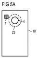
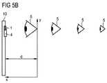
図5A及び図5Bに示されている実施例では、対象5の検出が、画像識別装置を用いて行われている。それに対して画像センサ4は、対象5の画像を検出するように構成されている。従ってここでの画像識別装置は、対象を識別すべく画像を評価できるように構成されている。ここでは画像中の対象5の大きさを介して、光源1と対象5との間の間隔xが推定されている。 In the embodiment shown in FIGS. 5A and 5B, the detection of the
ここに示されている対象5の検出のための手段を、図4A及び図4Bに基づいて説明した対象5の検出のための検出装置に結び付けて用いるならば、光11のビームパス内の対象5を検出するための冗長性のあるシステムが特に簡単に得られる。それに対しては、必ずしもさらなるセンサや受信器をポータブルエレクトロニクスデバイス内に設ける必要はない。 If the means for detection of the
本発明は、図面に基づいて説明してきた前述の実施例に限定されるものではない。それどころか本発明はあらゆる新たな特徴並びにそれらの特徴のあらゆる組み合わせも含み得るものである。このことは特に、特許請求の範囲に含まれている特徴のあらゆる組み合わせにも当てはまり、たとえ、これらの特徴若しくはその組み合わせ自体が特許請求の範囲や前記実施例の説明の中で述べられていなかったとしても否定されるものではない。 The invention is not limited to the embodiments described above with reference to the drawings. On the contrary, the present invention may include any new features as well as any combination of those features. This is especially true for any combination of features included in the claims, even if these features or combinations themselves were not stated in the claims or in the description of the examples. It is not denied.
この特許出願は、独国特許出願第102010011029.9号明細書の優先権を主張するものであり、この主張によってその開示内容も本願に反映されるものであることを最後に述べておく。 This patent application claims the priority of German Patent Application No. 102010011029.9, and it is finally stated that the content of the disclosure is also reflected in the present application by this claim.
Claims (15)
Translated fromJapanese前記光源(1)から作動中に放射される光(11)のビームパス内の前記光源(1)と対象(5)との間の間隔(x)を検出するための検出装置(23)とを有している、ポータブルエレクトロニクスデバイス(10)において、
前記検出装置(23)は、前記対象(5)が前記ビームパス内で、最低持続時間の間、光源(1)から最小間隔(d)の範囲内で検出された場合に、前記光源(1)から作動中に放射される光(11)の光束を低減するように構成されていることを特徴とするポータブルエレクトロニクスデバイス。A light source (1) comprising at least one luminescent diode and emitting light (11) during operation;
A detection device (23) for detectingthe spacing (x) between thelight source (1) and the object (5) in the beam path of light (11) emitted during operation from the light source (1); In a portable electronics device (10) having
The detection device (23) detects the light source (1) when the object (5) is detected within a minimum interval (d) from the light source (1) for a minimum duration in the beam path. Portable electronic device, characterized in that it is configured to reduce the luminous flux of light (11) emitted during operation.
前記光源(1)から作動中に放射される光(11)のビームパス内の前記光源(1)と対象(5)との間の間隔(x)を検出するための検出装置(23)とを有している、ポータブルエレクトロニクスデバイス(10)において、
前記検出装置(23)は、前記対象(5)が前記ビームパス内で、最低持続時間の間、前記光源(1)から最小間隔(d)の範囲内で検出された場合に、前記光源(1)から作動中に放射される光(11)の光束を低減するように構成されており、
a)前記検出装置(23)は、画像センサ(4)を含んでおり、該画像センサ(4)は、前記対象(5)の画像を検出するように構成されており、
前記検出装置(23)は、画像識別装置を含んでおり、該画像識別装置は、画像の評価と前記対象(5)の識別とを実施できるように構成されており、
前記検出装置(23)は、前記光源(1)と対象(5)との間の間隔(x)を、前記画像中の当該対象(5)の大きさに基づいて推定できるように構成されており、
又は、
b)前記検出装置(23)は、前記光源(1)を送信器として含んでおり、
前記検出装置(23)は、前記光源(1)と対象(5)との間の間隔(x)を、前記光源(1)による信号(11、21)の送信と、前記画像センサによる前記対象(5)において反射された信号(31)の受信との間の伝播時間の差分に基づいて求めるように構成されており、
前記ルミネセンスダイオードは発光ダイオードであり、さらに、
前記対象(5)は、人間の顔又は目である、
ことを特徴とするポータブルエレクトロニクスデバイス。A light source (1) comprising at least one luminescent diode and emitting light (11) during operation;
A detection device (23) for detectingthe spacing (x) between thelight source (1) and the object (5) in the beam path of light (11) emitted during operation from the light source (1); In a portable electronics device (10) having
The detection device (23) detects the light source (1) when the object (5) is detected within a minimum interval (d) from the light source (1) for a minimum duration in the beam path. ) To reduce the luminous flux of light (11) emitted during operation,
a) The detection device (23) includes an image sensor (4), and the image sensor (4) is configured to detect an image of the object (5);
The detection device (23) contains an image identification apparatus, the image identification apparatus is configured to implement the identification ofthe evaluation of the image object (5),
The detection device (23), the spacing (x) between said light source (1) and target (5), is configured to be estimated based on the size of the target inthe image (5) And
Or
b) The detection device (23) includes the light source (1) as a transmitter,
The detection device (23) determines the interval (x) between the light source (1) and the target (5), the transmission of signals (11, 21) by the light source (1), and the target by the image sensor. (5) configured to obtain based on a difference in propagation time from reception of the reflected signal (31);
The luminescence diode is a light emitting diode;
The object (5) is a human face or eye;
A portable electronic device characterized by that.
Applications Claiming Priority (3)
| Application Number | Priority Date | Filing Date | Title |
|---|---|---|---|
| DE102010011029.9 | 2010-03-11 | ||
| DE102010011029ADE102010011029A1 (en) | 2010-03-11 | 2010-03-11 | Portable electronic device |
| PCT/EP2011/052530WO2011110418A1 (en) | 2010-03-11 | 2011-02-21 | Portable electronic device |
Publications (2)
| Publication Number | Publication Date |
|---|---|
| JP2013526101A JP2013526101A (en) | 2013-06-20 |
| JP5579279B2true JP5579279B2 (en) | 2014-08-27 |
Family
ID=44260017
Family Applications (1)
| Application Number | Title | Priority Date | Filing Date |
|---|---|---|---|
| JP2012556433AActiveJP5579279B2 (en) | 2010-03-11 | 2011-02-21 | Portable electronics devices |
Country Status (8)
| Country | Link |
|---|---|
| US (1) | US8861789B2 (en) |
| EP (1) | EP2545696B1 (en) |
| JP (1) | JP5579279B2 (en) |
| KR (1) | KR101767516B1 (en) |
| CN (1) | CN102783123B (en) |
| DE (1) | DE102010011029A1 (en) |
| TW (1) | TWI451221B (en) |
| WO (1) | WO2011110418A1 (en) |
Families Citing this family (12)
| Publication number | Priority date | Publication date | Assignee | Title |
|---|---|---|---|---|
| US20140375772A1 (en)* | 2013-06-19 | 2014-12-25 | Thaddeus Gabara | Method and Apparatus for an SR and LR 3-D Visual Images and Sharing |
| DE102014221666A1 (en) | 2014-10-24 | 2016-04-28 | Osram Gmbh | lighting device |
| DE102014224035A1 (en) | 2014-11-25 | 2016-05-25 | Osram Gmbh | lighting device |
| DE202015001682U1 (en) | 2015-03-04 | 2015-03-24 | Osram Gmbh | lighting device |
| CN105097053B (en)* | 2015-05-29 | 2018-02-27 | 深圳奥比中光科技有限公司 | 3D rendering device, the protection device and its method of light radiation |
| US20170019577A1 (en)* | 2015-07-17 | 2017-01-19 | Dell Products L.P. | Safety circuit for infrared and laser imaging devices |
| TWI588587B (en)* | 2016-03-21 | 2017-06-21 | 鈺立微電子股份有限公司 | Image capture device and operation method thereof |
| DE102016207575A1 (en)* | 2016-05-03 | 2017-11-09 | Robert Bosch Gmbh | Holding device for the adjustable attachment of an attachment to a hand tool, and hand tool with such a holding device |
| NO347923B1 (en)* | 2017-09-15 | 2024-05-13 | Elliptic Laboratories Asa | User Authentication Control |
| CN109040541A (en)* | 2018-07-20 | 2018-12-18 | 努比亚技术有限公司 | Terminal flash lamp uses control method, terminal and computer readable storage medium |
| DE102019103738A1 (en)* | 2019-02-14 | 2020-08-20 | Automotive Lighting Reutlingen Gmbh | Laser projection device for a motor vehicle |
| CN110022632A (en)* | 2019-04-19 | 2019-07-16 | 青岛亿联客信息技术有限公司 | A kind of adjusting method, device, system and the readable storage medium storing program for executing of lamps and lanterns luminous flux |
Family Cites Families (26)
| Publication number | Priority date | Publication date | Assignee | Title |
|---|---|---|---|---|
| JPS618774A (en) | 1984-06-22 | 1986-01-16 | Hitachi Ltd | Reading circuit of magnetic recording/reproducing device |
| US4716469A (en)* | 1985-10-25 | 1987-12-29 | Gold Star Co., Ltd. | Circuit for eyesight protection in a television set |
| JPH05253188A (en) | 1992-03-16 | 1993-10-05 | Topcon Corp | Optic axial length measuring instrument |
| JPH0618774A (en)* | 1992-03-18 | 1994-01-28 | Nikon Corp | Camera with eye-gaze detector |
| JPH07140377A (en)* | 1993-11-18 | 1995-06-02 | Olympus Optical Co Ltd | Camera provided with range-finding device |
| IL111852A (en)* | 1994-12-02 | 2002-07-25 | Elop Electrooptics Ind Ltd | System for eye protection from laser radiation |
| US6710770B2 (en) | 2000-02-11 | 2004-03-23 | Canesta, Inc. | Quasi-three-dimensional method and apparatus to detect and localize interaction of user-object and virtual transfer device |
| JP2001141986A (en)* | 1999-11-16 | 2001-05-25 | Olympus Optical Co Ltd | Electronic camera and automatic focusing device for electronic camera |
| KR100734894B1 (en) | 2000-09-07 | 2007-07-03 | 카네스타, 인코포레이티드 | Quasi-three-dimensional methods and devices for exploring and placing interactions between user objects and virtual input devices |
| JP5019668B2 (en)* | 2000-09-18 | 2012-09-05 | 三洋電機株式会社 | Display device and control method thereof |
| JP2002335317A (en)* | 2001-05-11 | 2002-11-22 | Mitsubishi Electric Corp | Mobile terminal |
| JP4666821B2 (en) | 2001-06-29 | 2011-04-06 | キヤノン株式会社 | Ophthalmic equipment |
| JP2004325609A (en)* | 2003-04-23 | 2004-11-18 | Nec Saitama Ltd | Cellar phone unit |
| JPWO2005081020A1 (en)* | 2004-02-19 | 2008-05-15 | キヤノン株式会社 | Optics and beam splitters |
| US20060132431A1 (en) | 2004-12-17 | 2006-06-22 | Eliezer Oren E | Multi-function digital device as a human-input-device for a computer |
| JP4551295B2 (en) | 2005-08-11 | 2010-09-22 | 富士フイルム株式会社 | Imaging device |
| WO2007036838A1 (en) | 2005-09-30 | 2007-04-05 | Philips Intellectual Property & Standards Gmbh | Face annotation in streaming video |
| JP2007324877A (en) | 2006-05-31 | 2007-12-13 | Fujifilm Corp | Imaging device |
| JP2007328213A (en)* | 2006-06-09 | 2007-12-20 | Sony Corp | Imaging apparatus, imaging apparatus control method, and computer program |
| KR101146077B1 (en)* | 2006-09-06 | 2012-05-15 | 엘지이노텍 주식회사 | Method and system for recognizing biotic information in mobile phone |
| JP5058632B2 (en)* | 2007-03-02 | 2012-10-24 | キヤノン株式会社 | Imaging device |
| CN102016633B (en) | 2008-03-20 | 2016-11-23 | 塞德斯股份公司 | Sensor for monitoring a monitored area |
| KR101495164B1 (en)* | 2008-04-10 | 2015-02-24 | 엘지전자 주식회사 | Mobile terminal and its screen processing method |
| TWM362341U (en) | 2008-06-26 | 2009-08-01 | Min-Chuan Lin | Illumination-adjustable smart green lighting device |
| JP2010081480A (en)* | 2008-09-29 | 2010-04-08 | Fujifilm Corp | Portable suspicious individual detecting apparatus, suspicious individual detecting method, and program |
| WO2011011009A1 (en) | 2009-07-23 | 2011-01-27 | Hewlett-Packard Development Company, L.P. | Display with an optical sensor |
- 2010
- 2010-03-11DEDE102010011029Apatent/DE102010011029A1/ennot_activeWithdrawn
- 2011
- 2011-02-21EPEP11705517.8Apatent/EP2545696B1/enactiveActive
- 2011-02-21WOPCT/EP2011/052530patent/WO2011110418A1/enactiveApplication Filing
- 2011-02-21KRKR1020127026643Apatent/KR101767516B1/enactiveActive
- 2011-02-21USUS13/583,812patent/US8861789B2/enactiveActive
- 2011-02-21JPJP2012556433Apatent/JP5579279B2/enactiveActive
- 2011-02-21CNCN201180013497.5Apatent/CN102783123B/enactiveActive
- 2011-03-09TWTW100107833Apatent/TWI451221B/ennot_activeIP Right Cessation
Also Published As
| Publication number | Publication date |
|---|---|
| KR20130052554A (en) | 2013-05-22 |
| EP2545696B1 (en) | 2016-04-20 |
| TW201144964A (en) | 2011-12-16 |
| US8861789B2 (en) | 2014-10-14 |
| KR101767516B1 (en) | 2017-08-11 |
| WO2011110418A1 (en) | 2011-09-15 |
| TWI451221B (en) | 2014-09-01 |
| US20130039539A1 (en) | 2013-02-14 |
| CN102783123B (en) | 2015-11-25 |
| CN102783123A (en) | 2012-11-14 |
| DE102010011029A1 (en) | 2011-09-15 |
| EP2545696A1 (en) | 2013-01-16 |
| JP2013526101A (en) | 2013-06-20 |
Similar Documents
| Publication | Publication Date | Title |
|---|---|---|
| JP5579279B2 (en) | Portable electronics devices | |
| JP4805991B2 (en) | Security system using laser distance measuring device and intruder detection method using laser distance measuring device | |
| KR101709348B1 (en) | Apparatus and method for generating visible signal according to data transmitting rate in visible light communication system | |
| CN107884066A (en) | Optical sensor and its 3D imaging devices based on flood lighting function | |
| JP2014534568A (en) | Encoded photodetector | |
| CA2638520A1 (en) | Vehicle illumination system | |
| CN102016633B (en) | Sensor for monitoring a monitored area | |
| US11483071B2 (en) | Optical wireless communication device | |
| KR101297759B1 (en) | Ir led controlling apparatus for cctv and method thereof | |
| US9031694B2 (en) | Entry detection device, robot, and entry detection method | |
| US20190280770A1 (en) | Method and apparatus for free-space optical transmission | |
| JP2007206059A (en) | Photoelectric device and operating method of photoelectric device | |
| KR20180051240A (en) | Device and method for detecting a hidden camera | |
| US20120039592A1 (en) | Video camera supplementary white light control method | |
| JP2010217093A (en) | Positioning system | |
| JP2014174194A (en) | Projector safety device, projector including the same, and projector safety control method | |
| JP6183748B2 (en) | Motion detection device | |
| JP2013083547A (en) | Intrusion detection device, robot, intrusion detection method and intrusion detection program | |
| JP2013187804A (en) | Monitoring camera | |
| KR200385668Y1 (en) | Duplex infrared sensor | |
| CN212413327U (en) | Projector capable of preventing strong light from mistakenly irradiating human eyes | |
| RU2541889C2 (en) | Method of selecting controlled device | |
| JP2013073563A (en) | Intrusion detection device, robot, intrusion detection method and intrusion detection program | |
| KR101521530B1 (en) | Survailance system and method using light | |
| JP2007116307A (en) | Imaging device and lighting device |
Legal Events
| Date | Code | Title | Description |
|---|---|---|---|
| A977 | Report on retrieval | Free format text:JAPANESE INTERMEDIATE CODE: A971007 Effective date:20131007 | |
| A131 | Notification of reasons for refusal | Free format text:JAPANESE INTERMEDIATE CODE: A131 Effective date:20131015 | |
| A601 | Written request for extension of time | Free format text:JAPANESE INTERMEDIATE CODE: A601 Effective date:20131203 | |
| A602 | Written permission of extension of time | Free format text:JAPANESE INTERMEDIATE CODE: A602 Effective date:20131210 | |
| A521 | Request for written amendment filed | Free format text:JAPANESE INTERMEDIATE CODE: A523 Effective date:20140410 | |
| TRDD | Decision of grant or rejection written | ||
| A01 | Written decision to grant a patent or to grant a registration (utility model) | Free format text:JAPANESE INTERMEDIATE CODE: A01 Effective date:20140609 | |
| A61 | First payment of annual fees (during grant procedure) | Free format text:JAPANESE INTERMEDIATE CODE: A61 Effective date:20140708 | |
| R150 | Certificate of patent or registration of utility model | Ref document number:5579279 Country of ref document:JP Free format text:JAPANESE INTERMEDIATE CODE: R150 | |
| R250 | Receipt of annual fees | Free format text:JAPANESE INTERMEDIATE CODE: R250 | |
| R250 | Receipt of annual fees | Free format text:JAPANESE INTERMEDIATE CODE: R250 | |
| R250 | Receipt of annual fees | Free format text:JAPANESE INTERMEDIATE CODE: R250 | |
| R250 | Receipt of annual fees | Free format text:JAPANESE INTERMEDIATE CODE: R250 | |
| R250 | Receipt of annual fees | Free format text:JAPANESE INTERMEDIATE CODE: R250 | |
| R250 | Receipt of annual fees | Free format text:JAPANESE INTERMEDIATE CODE: R250 | |
| R250 | Receipt of annual fees | Free format text:JAPANESE INTERMEDIATE CODE: R250 | |
| R250 | Receipt of annual fees | Free format text:JAPANESE INTERMEDIATE CODE: R250 | |
| R250 | Receipt of annual fees | Free format text:JAPANESE INTERMEDIATE CODE: R250 |