JP5578864B2 - Repair method of wall member with flow path - Google Patents
Repair method of wall member with flow pathDownload PDFInfo
- Publication number
- JP5578864B2 JP5578864B2JP2010009990AJP2010009990AJP5578864B2JP 5578864 B2JP5578864 B2JP 5578864B2JP 2010009990 AJP2010009990 AJP 2010009990AJP 2010009990 AJP2010009990 AJP 2010009990AJP 5578864 B2JP5578864 B2JP 5578864B2
- Authority
- JP
- Japan
- Prior art keywords
- welding
- repair
- flow path
- wall member
- base material
- Prior art date
- Legal status (The legal status is an assumption and is not a legal conclusion. Google has not performed a legal analysis and makes no representation as to the accuracy of the status listed.)
- Active
Links
- 230000008439repair processEffects0.000titleclaimsdescription103
- 238000000034methodMethods0.000titleclaimsdescription48
- 238000003466weldingMethods0.000claimsdescription123
- 239000000463materialSubstances0.000claimsdescription91
- 239000011324beadSubstances0.000claimsdescription45
- 239000000843powderSubstances0.000claimsdescription14
- 238000010894electron beam technologyMethods0.000claimsdescription6
- 230000001678irradiating effectEffects0.000claimsdescription2
- 238000001816coolingMethods0.000description19
- 230000000694effectsEffects0.000description5
- 230000007704transitionEffects0.000description4
- RYGMFSIKBFXOCR-UHFFFAOYSA-NCopperChemical compound[Cu]RYGMFSIKBFXOCR-UHFFFAOYSA-N0.000description3
- PXHVJJICTQNCMI-UHFFFAOYSA-NNickelChemical compound[Ni]PXHVJJICTQNCMI-UHFFFAOYSA-N0.000description2
- 239000010953base metalSubstances0.000description2
- 238000005219brazingMethods0.000description2
- 238000010276constructionMethods0.000description2
- 239000000945fillerSubstances0.000description2
- 239000002184metalSubstances0.000description2
- 229910052751metalInorganic materials0.000description2
- 238000004021metal weldingMethods0.000description2
- 150000002739metalsChemical class0.000description2
- 229910000601superalloyInorganic materials0.000description2
- 238000009941weavingMethods0.000description2
- 238000005336crackingMethods0.000description1
- 229910000856hastalloyInorganic materials0.000description1
- 229910001063inconels 617Inorganic materials0.000description1
- 229910001119inconels 625Inorganic materials0.000description1
- 235000013372meatNutrition0.000description1
- 229910052759nickelInorganic materials0.000description1
- 239000002245particleSubstances0.000description1
- 238000012805post-processingMethods0.000description1
Images


Classifications
- B—PERFORMING OPERATIONS; TRANSPORTING
- B23—MACHINE TOOLS; METAL-WORKING NOT OTHERWISE PROVIDED FOR
- B23P—METAL-WORKING NOT OTHERWISE PROVIDED FOR; COMBINED OPERATIONS; UNIVERSAL MACHINE TOOLS
- B23P6/00—Restoring or reconditioning objects
- B23P6/002—Repairing turbine components, e.g. moving or stationary blades, rotors
- B—PERFORMING OPERATIONS; TRANSPORTING
- B23—MACHINE TOOLS; METAL-WORKING NOT OTHERWISE PROVIDED FOR
- B23K—SOLDERING OR UNSOLDERING; WELDING; CLADDING OR PLATING BY SOLDERING OR WELDING; CUTTING BY APPLYING HEAT LOCALLY, e.g. FLAME CUTTING; WORKING BY LASER BEAM
- B23K26/00—Working by laser beam, e.g. welding, cutting or boring
- B23K26/20—Bonding
- B23K26/21—Bonding by welding
- B—PERFORMING OPERATIONS; TRANSPORTING
- B23—MACHINE TOOLS; METAL-WORKING NOT OTHERWISE PROVIDED FOR
- B23K—SOLDERING OR UNSOLDERING; WELDING; CLADDING OR PLATING BY SOLDERING OR WELDING; CUTTING BY APPLYING HEAT LOCALLY, e.g. FLAME CUTTING; WORKING BY LASER BEAM
- B23K10/00—Welding or cutting by means of a plasma
- B23K10/02—Plasma welding
- B23K10/027—Welding for purposes other than joining, e.g. build-up welding
- B—PERFORMING OPERATIONS; TRANSPORTING
- B23—MACHINE TOOLS; METAL-WORKING NOT OTHERWISE PROVIDED FOR
- B23K—SOLDERING OR UNSOLDERING; WELDING; CLADDING OR PLATING BY SOLDERING OR WELDING; CUTTING BY APPLYING HEAT LOCALLY, e.g. FLAME CUTTING; WORKING BY LASER BEAM
- B23K15/00—Electron-beam welding or cutting
- B23K15/0046—Welding
- B23K15/0086—Welding welding for purposes other than joining, e.g. built-up welding
- B—PERFORMING OPERATIONS; TRANSPORTING
- B23—MACHINE TOOLS; METAL-WORKING NOT OTHERWISE PROVIDED FOR
- B23K—SOLDERING OR UNSOLDERING; WELDING; CLADDING OR PLATING BY SOLDERING OR WELDING; CUTTING BY APPLYING HEAT LOCALLY, e.g. FLAME CUTTING; WORKING BY LASER BEAM
- B23K26/00—Working by laser beam, e.g. welding, cutting or boring
- B23K26/14—Working by laser beam, e.g. welding, cutting or boring using a fluid stream, e.g. a jet of gas, in conjunction with the laser beam; Nozzles therefor
- B23K26/142—Working by laser beam, e.g. welding, cutting or boring using a fluid stream, e.g. a jet of gas, in conjunction with the laser beam; Nozzles therefor for the removal of by-products
- B—PERFORMING OPERATIONS; TRANSPORTING
- B23—MACHINE TOOLS; METAL-WORKING NOT OTHERWISE PROVIDED FOR
- B23K—SOLDERING OR UNSOLDERING; WELDING; CLADDING OR PLATING BY SOLDERING OR WELDING; CUTTING BY APPLYING HEAT LOCALLY, e.g. FLAME CUTTING; WORKING BY LASER BEAM
- B23K26/00—Working by laser beam, e.g. welding, cutting or boring
- B23K26/14—Working by laser beam, e.g. welding, cutting or boring using a fluid stream, e.g. a jet of gas, in conjunction with the laser beam; Nozzles therefor
- B23K26/144—Working by laser beam, e.g. welding, cutting or boring using a fluid stream, e.g. a jet of gas, in conjunction with the laser beam; Nozzles therefor the fluid stream containing particles, e.g. powder
- B—PERFORMING OPERATIONS; TRANSPORTING
- B23—MACHINE TOOLS; METAL-WORKING NOT OTHERWISE PROVIDED FOR
- B23K—SOLDERING OR UNSOLDERING; WELDING; CLADDING OR PLATING BY SOLDERING OR WELDING; CUTTING BY APPLYING HEAT LOCALLY, e.g. FLAME CUTTING; WORKING BY LASER BEAM
- B23K26/00—Working by laser beam, e.g. welding, cutting or boring
- B23K26/20—Bonding
- B23K26/32—Bonding taking account of the properties of the material involved
- B23K26/322—Bonding taking account of the properties of the material involved involving coated metal parts
- B—PERFORMING OPERATIONS; TRANSPORTING
- B23—MACHINE TOOLS; METAL-WORKING NOT OTHERWISE PROVIDED FOR
- B23K—SOLDERING OR UNSOLDERING; WELDING; CLADDING OR PLATING BY SOLDERING OR WELDING; CUTTING BY APPLYING HEAT LOCALLY, e.g. FLAME CUTTING; WORKING BY LASER BEAM
- B23K26/00—Working by laser beam, e.g. welding, cutting or boring
- B23K26/20—Bonding
- B23K26/32—Bonding taking account of the properties of the material involved
- B23K26/323—Bonding taking account of the properties of the material involved involving parts made of dissimilar metallic material
- B—PERFORMING OPERATIONS; TRANSPORTING
- B23—MACHINE TOOLS; METAL-WORKING NOT OTHERWISE PROVIDED FOR
- B23K—SOLDERING OR UNSOLDERING; WELDING; CLADDING OR PLATING BY SOLDERING OR WELDING; CUTTING BY APPLYING HEAT LOCALLY, e.g. FLAME CUTTING; WORKING BY LASER BEAM
- B23K26/00—Working by laser beam, e.g. welding, cutting or boring
- B23K26/34—Laser welding for purposes other than joining
- B23K26/342—Build-up welding
- B—PERFORMING OPERATIONS; TRANSPORTING
- B23—MACHINE TOOLS; METAL-WORKING NOT OTHERWISE PROVIDED FOR
- B23K—SOLDERING OR UNSOLDERING; WELDING; CLADDING OR PLATING BY SOLDERING OR WELDING; CUTTING BY APPLYING HEAT LOCALLY, e.g. FLAME CUTTING; WORKING BY LASER BEAM
- B23K26/00—Working by laser beam, e.g. welding, cutting or boring
- B23K26/346—Working by laser beam, e.g. welding, cutting or boring in combination with welding or cutting covered by groups B23K5/00 - B23K25/00, e.g. in combination with resistance welding
- B—PERFORMING OPERATIONS; TRANSPORTING
- B23—MACHINE TOOLS; METAL-WORKING NOT OTHERWISE PROVIDED FOR
- B23K—SOLDERING OR UNSOLDERING; WELDING; CLADDING OR PLATING BY SOLDERING OR WELDING; CUTTING BY APPLYING HEAT LOCALLY, e.g. FLAME CUTTING; WORKING BY LASER BEAM
- B23K35/00—Rods, electrodes, materials, or media, for use in soldering, welding, or cutting
- B23K35/02—Rods, electrodes, materials, or media, for use in soldering, welding, or cutting characterised by mechanical features, e.g. shape
- B23K35/0222—Rods, electrodes, materials, or media, for use in soldering, welding, or cutting characterised by mechanical features, e.g. shape for use in soldering, brazing
- B23K35/0244—Powders, particles or spheres; Preforms made therefrom
- B—PERFORMING OPERATIONS; TRANSPORTING
- B23—MACHINE TOOLS; METAL-WORKING NOT OTHERWISE PROVIDED FOR
- B23K—SOLDERING OR UNSOLDERING; WELDING; CLADDING OR PLATING BY SOLDERING OR WELDING; CUTTING BY APPLYING HEAT LOCALLY, e.g. FLAME CUTTING; WORKING BY LASER BEAM
- B23K35/00—Rods, electrodes, materials, or media, for use in soldering, welding, or cutting
- B23K35/22—Rods, electrodes, materials, or media, for use in soldering, welding, or cutting characterised by the composition or nature of the material
- B23K35/24—Selection of soldering or welding materials proper
- B23K35/30—Selection of soldering or welding materials proper with the principal constituent melting at less than 1550 degrees C
- B23K35/3033—Ni as the principal constituent
- B—PERFORMING OPERATIONS; TRANSPORTING
- B23—MACHINE TOOLS; METAL-WORKING NOT OTHERWISE PROVIDED FOR
- B23K—SOLDERING OR UNSOLDERING; WELDING; CLADDING OR PLATING BY SOLDERING OR WELDING; CUTTING BY APPLYING HEAT LOCALLY, e.g. FLAME CUTTING; WORKING BY LASER BEAM
- B23K9/00—Arc welding or cutting
- B23K9/04—Welding for other purposes than joining, e.g. built-up welding
- B23K9/044—Built-up welding on three-dimensional surfaces
- F—MECHANICAL ENGINEERING; LIGHTING; HEATING; WEAPONS; BLASTING
- F01—MACHINES OR ENGINES IN GENERAL; ENGINE PLANTS IN GENERAL; STEAM ENGINES
- F01D—NON-POSITIVE DISPLACEMENT MACHINES OR ENGINES, e.g. STEAM TURBINES
- F01D25/00—Component parts, details, or accessories, not provided for in, or of interest apart from, other groups
- F01D25/28—Supporting or mounting arrangements, e.g. for turbine casing
- F01D25/285—Temporary support structures, e.g. for testing, assembling, installing, repairing; Assembly methods using such structures
- F—MECHANICAL ENGINEERING; LIGHTING; HEATING; WEAPONS; BLASTING
- F02—COMBUSTION ENGINES; HOT-GAS OR COMBUSTION-PRODUCT ENGINE PLANTS
- F02C—GAS-TURBINE PLANTS; AIR INTAKES FOR JET-PROPULSION PLANTS; CONTROLLING FUEL SUPPLY IN AIR-BREATHING JET-PROPULSION PLANTS
- F02C7/00—Features, components parts, details or accessories, not provided for in, or of interest apart form groups F02C1/00 - F02C6/00; Air intakes for jet-propulsion plants
- B—PERFORMING OPERATIONS; TRANSPORTING
- B23—MACHINE TOOLS; METAL-WORKING NOT OTHERWISE PROVIDED FOR
- B23K—SOLDERING OR UNSOLDERING; WELDING; CLADDING OR PLATING BY SOLDERING OR WELDING; CUTTING BY APPLYING HEAT LOCALLY, e.g. FLAME CUTTING; WORKING BY LASER BEAM
- B23K2101/00—Articles made by soldering, welding or cutting
- B23K2101/001—Turbines
- B—PERFORMING OPERATIONS; TRANSPORTING
- B23—MACHINE TOOLS; METAL-WORKING NOT OTHERWISE PROVIDED FOR
- B23K—SOLDERING OR UNSOLDERING; WELDING; CLADDING OR PLATING BY SOLDERING OR WELDING; CUTTING BY APPLYING HEAT LOCALLY, e.g. FLAME CUTTING; WORKING BY LASER BEAM
- B23K2101/00—Articles made by soldering, welding or cutting
- B23K2101/34—Coated articles, e.g. plated or painted; Surface treated articles
- B—PERFORMING OPERATIONS; TRANSPORTING
- B23—MACHINE TOOLS; METAL-WORKING NOT OTHERWISE PROVIDED FOR
- B23K—SOLDERING OR UNSOLDERING; WELDING; CLADDING OR PLATING BY SOLDERING OR WELDING; CUTTING BY APPLYING HEAT LOCALLY, e.g. FLAME CUTTING; WORKING BY LASER BEAM
- B23K2103/00—Materials to be soldered, welded or cut
- B23K2103/08—Non-ferrous metals or alloys
- B—PERFORMING OPERATIONS; TRANSPORTING
- B23—MACHINE TOOLS; METAL-WORKING NOT OTHERWISE PROVIDED FOR
- B23K—SOLDERING OR UNSOLDERING; WELDING; CLADDING OR PLATING BY SOLDERING OR WELDING; CUTTING BY APPLYING HEAT LOCALLY, e.g. FLAME CUTTING; WORKING BY LASER BEAM
- B23K2103/00—Materials to be soldered, welded or cut
- B23K2103/18—Dissimilar materials
- B23K2103/26—Alloys of Nickel and Cobalt and Chromium
- B—PERFORMING OPERATIONS; TRANSPORTING
- B23—MACHINE TOOLS; METAL-WORKING NOT OTHERWISE PROVIDED FOR
- B23P—METAL-WORKING NOT OTHERWISE PROVIDED FOR; COMBINED OPERATIONS; UNIVERSAL MACHINE TOOLS
- B23P2700/00—Indexing scheme relating to the articles being treated, e.g. manufactured, repaired, assembled, connected or other operations covered in the subgroups
- B23P2700/13—Parts of turbine combustion chambers
- F—MECHANICAL ENGINEERING; LIGHTING; HEATING; WEAPONS; BLASTING
- F05—INDEXING SCHEMES RELATING TO ENGINES OR PUMPS IN VARIOUS SUBCLASSES OF CLASSES F01-F04
- F05D—INDEXING SCHEME FOR ASPECTS RELATING TO NON-POSITIVE-DISPLACEMENT MACHINES OR ENGINES, GAS-TURBINES OR JET-PROPULSION PLANTS
- F05D2230/00—Manufacture
- F05D2230/20—Manufacture essentially without removing material
- F05D2230/23—Manufacture essentially without removing material by permanently joining parts together
- F05D2230/232—Manufacture essentially without removing material by permanently joining parts together by welding
- F—MECHANICAL ENGINEERING; LIGHTING; HEATING; WEAPONS; BLASTING
- F05—INDEXING SCHEMES RELATING TO ENGINES OR PUMPS IN VARIOUS SUBCLASSES OF CLASSES F01-F04
- F05D—INDEXING SCHEME FOR ASPECTS RELATING TO NON-POSITIVE-DISPLACEMENT MACHINES OR ENGINES, GAS-TURBINES OR JET-PROPULSION PLANTS
- F05D2230/00—Manufacture
- F05D2230/80—Repairing, retrofitting or upgrading methods
- F—MECHANICAL ENGINEERING; LIGHTING; HEATING; WEAPONS; BLASTING
- F23—COMBUSTION APPARATUS; COMBUSTION PROCESSES
- F23R—GENERATING COMBUSTION PRODUCTS OF HIGH PRESSURE OR HIGH VELOCITY, e.g. GAS-TURBINE COMBUSTION CHAMBERS
- F23R2900/00—Special features of, or arrangements for continuous combustion chambers; Combustion processes therefor
- F23R2900/00019—Repairing or maintaining combustion chamber liners or subparts
Landscapes
- Engineering & Computer Science (AREA)
- Mechanical Engineering (AREA)
- Physics & Mathematics (AREA)
- Optics & Photonics (AREA)
- Plasma & Fusion (AREA)
- General Engineering & Computer Science (AREA)
- Chemical & Material Sciences (AREA)
- Combustion & Propulsion (AREA)
- Laser Beam Processing (AREA)
- Welding Or Cutting Using Electron Beams (AREA)
- Butt Welding And Welding Of Specific Article (AREA)
Description
Translated fromJapanese本発明は、例えば、ガスタービンの燃焼器のような流路付き壁部材の部分的な補修方法に関するものである。 The present invention relates to a method for partially repairing a wall member with a flow path such as a combustor of a gas turbine, for example.
一般に、ガスタービンの燃焼器の損傷部分の補修方法としては、損傷が生じた部材全体の交換や部品交換が行われている(例えば、特許文献1)。
また、特許文献2には、燃焼器のような内部に流路(以下「冷却溝」という。)を有する板にクラックが発生した場合についての補修方法が開示されている。Generally, as a repair method for a damaged portion of a combustor of a gas turbine, replacement of the entire damaged member or replacement of a part is performed (for example, Patent Document 1).
しかしながら、冷却溝を有する燃焼器の尾筒に損傷が生じた場合の補修方法は、損傷部分を除去して尾筒のガスパスを形成する母材の一部を削除部分に周溶接し、母材上にグラインダによって冷却溝となる流路を作成する。その後、作成された流路に銅ワイヤを挿入して銅ワイヤの上部を溶接した後、銅ワイヤを流路から引き出して冷却溝を形成するという補修を行っていた。そのため、冷却効果を高めるために冷却溝の間隔を狭くして作成される燃焼器の尾筒を補修する場合には、グラインダによって冷却溝を作成することができず尾筒を構成しているパネル毎交換するため補修に要する時間とコストとがかさむという問題があった。
特許文献2に記載の発明は、広範囲に渡るクラックが発生した場合には、補修工事に要する時間とコストとがかさむという問題があった。However, the repair method in the case where damage has occurred to the combustor of the combustor having the cooling groove, the part of the base material that forms the gas path of the tail pipe by removing the damaged part is circumferential welded to the base part, A flow path serving as a cooling groove is created by a grinder. After that, after the copper wire was inserted into the created flow path and the upper part of the copper wire was welded, the copper wire was pulled out of the flow path to form a cooling groove. Therefore, when repairing a combustor tail pipe that is created with a narrow cooling groove interval in order to enhance the cooling effect, a cooling groove cannot be created by a grinder, and the panel constituting the tail pipe There was a problem that the time and cost required for repairs were increased because each replacement was required.
The invention described in
本発明は、このような事情に鑑みてなされたものであって、流路付き壁部材の部分的な補修工事に要する時間とコストとを削減することができる補修方法を提供することを目的とする。 This invention is made in view of such a situation, Comprising: It aims at providing the repair method which can reduce the time and cost which a partial repair construction of a wall member with a flow path requires. To do.
上記課題を解決するために、本発明の流路付き壁部材の補修方法は、以下の手段を採用する。
すなわち、本発明に係る流路付き壁部材の補修方法によれば、母材と板材との間に複数の流路を有する壁部材の一部分を除去する除去工程と、前記母材のうちの該除去工程にて除去されていない部分に補修用母材を周溶接する母材溶接工程と、前記補修用母材上に複数の肉盛溶接を行い、複数のビードを形成する流路形成工程と、前記複数のビードの間に流路が形成されるように、前記板材のうちの該除去工程にて除去されていない部分の表面と同じ高さの補修表面を形成する板材溶接工程と、を備えたことを特徴とする。In order to solve the above problems, the repairing method for a wall member with a flow path of the present invention employs the following means.
That is, according to the method for repairing a wall member with a flow path according to the present invention, a removal step of removing a part of the wall member having a plurality of flow paths between the base material and the platematerial, A base material welding step ofcircumferentially welding a repair base material to a portionnot removed in the removal step, and a flow path forming step of performing aplurality of overlay weldings on the repair base material to form aplurality of beads A plate material welding stepfor forming arepair surface having the same height as the surface of the portion of the plate materialthat has not been removed in the removal step so that a flow path is formed between the plurality of beads. It is characterized by having.
従来は、母材と板材との間に複数の流路を有する壁部材の一部を除去する場合には、その部分を除去して補修用母材を周溶接し、補修用母材上にグラインダによって流路を作成していた。しかし、補修用母材上に形成される流路間の間隔が狭くなった場合には、グラインダによる流路の形成が困難になる。そこで、本発明は、補修用母材上に肉盛溶接を複数行うこととした。そのため、間隔が狭い流路を有する壁部材の補修をすることができる。したがって、流路付き壁部材の補修コストを抑えることができる。Conventionally, when a part of a wall member having a plurality of flow paths between a base material and a plate material is removed, the part is removed and the repair base material is circumferentially welded, and the repair base material is placed on the repair base material. A flow path was created by a grinder. However, when the interval between the flow paths formed on the repair base material becomes narrow, it becomes difficult to form the flow path by the grinder. Accordingly, the present invention is, was itintends multiple lines overlay welding on repair preform. Therefore, it is possible to repair a wall member having a flow path with a narrow interval. Therefore, the repair cost of the wall member with a flow path can be suppressed.
さらに、本発明に係る流路付き壁部材の補修方法によれば、前記肉盛溶接は、溶接材粉末を用いたレーザ溶接、又は電子ビーム溶接であることを特徴とする。 Furthermore, according to the method for repairing a wall member with a flow path according to the present invention, the build-up welding is laser welding using a welding material powder or electron beam welding.
溶接材粉末を用いたレーザ溶接又は電子ビーム溶接によって肉盛溶接をすることとした。そのため、幅の狭い細い溶接を施工することができる。したがって、補修用母材上に間隔が狭い流路を作成することができる。 Overlay welding was performed by laser welding or electron beam welding using the welding material powder. Therefore, narrow and narrow welding can be performed. Therefore, it is possible to create a flow path having a narrow interval on the repair base material.
さらに、本発明に係る流路付き壁部材の補修方法によれば、前記流路形成工程は、前記補修用母材上に複数の前記肉盛溶接を行う前に、前記補修用母材上に複数の管を設け、前記肉盛溶接によって複数の前記管の間を溶接し、前記板材溶接工程は、肉盛溶接することにより前記補修表面を形成することを特徴とする。Further, according to the method for repairing a wall member with a flow path according to the present invention, the flow path forming step is performed on the repair base material before performing the plurality of overlay weldings on the repair base material. A plurality of pipes are provided, the plurality of pipes are welded by the overlay welding,and the plate material welding step forms therepair surface by overlay welding .
補修用母材上に複数の管を設けて、それらの管の間に肉盛溶接をすることとした。そのため、肉盛溶接の高さは、管の高さに合わせ、肉盛溶接を行う幅は、管と管との間隔に合わせて溶接することができる。したがって、肉盛溶接に要する時間を短縮することができる。 A plurality of pipes were provided on the repair base material, and overlay welding was performed between these pipes. Therefore, the height of overlay welding can be matched to the height of the tube, and the width for overlay welding can be welded according to the interval between the tubes. Therefore, the time required for overlay welding can be shortened.
前記板材溶接工程は、前記複数のビードに補修用板材を溶接することにより、前記流路を形成する。
さらに、本発明に係る流路付き壁部材の補修方法によれば、前記補修用板材のうちの複数の前記肉盛溶接に溶接される面の反対面には、更に肉盛溶接を行う工程を備えることを特徴とする。In the plate material welding step, the flow path is formed by welding a repair plate material to the plurality of beads.
Further, according to the method for repairing with flow passage wall member according to the presentinvention, the surface opposite tothe surface to be welded to a plurality of the overlay welding of theprevious SL repair plate, the step of further performing overlay welding It is characterized by providing.
肉盛溶接の表面または肉盛溶接の表面に溶接される補修用板材の反対面には、更に肉盛溶接を行うこととした。そのため、肉盛溶接または肉盛溶接をした補修用板材を任意の厚み、形状にすることができる。したがって、既存の流路付き壁部材と形状を合わせることができる。 On the opposite surface of the plate for repair welded to the surface of overlay welding or the surface of overlay welding, overlay welding was further performed. Therefore, the plate material for repair which carried out overlay welding or overlay welding can be made into arbitrary thickness and shape. Therefore, the shape can be matched with the existing wall member with a flow path.
さらに、本発明に係る流路付き壁部材の補修方法によれば、前記補修用板材には、複数の開先が設けられることを特徴とする。 Furthermore, according to the repair method of the wall member with a flow path according to the present invention, the repair plate is provided with a plurality of grooves.
開先を補修用板材に設けることとした。そのため、補修用板材を肉盛溶接の表面に溶接する際に、溶接を行う位置を目視することができる。したがって、溶接忘れを防止することができる。
前記補修用板材は、前記複数の開先の中央部と各ビードの中央部とを貫通するようにレーザが照射されることにより、前記複数のビードに溶接される。
以上の補修方法は,レーザの代わりに電子ビームを用いた溶接でも良い。その場合は、燃焼器を真空チャンバに設置し補修を行う。
本発明に係るガスタービン燃焼器は、本発明に係る流路付き壁部材の補修方法により補修される。A groove was provided on the repair plate. Therefore, when welding the plate material for repair to the surface of overlay welding, the position which welds can be visually observed. Therefore, forgetting to weld can be prevented.
The repair plate is welded to the plurality of beads by irradiating a laser so as to pass through the central portion of the plurality of grooves and the central portion of each bead.
The above repair method may be welding using an electron beam instead of a laser. In that case, the combustor is installed in the vacuum chamber and repaired.
The gas turbine combustor according to the present invention is repaired by the method for repairing a wall member with a flow path according to the present invention.
補修用母材上に肉盛溶接を複数行い、それらの肉盛溶接の表面に補修用板材を溶接することとした。そのため、間隔が狭い流路を有する壁部材の補修をすることができる。したがって、流路付き壁部材の補修コストを抑えることができる。 A plurality of overlay weldings were performed on the repair base material, and the repair plate was welded to the surface of the overlay welding. Therefore, it is possible to repair a wall member having a flow path with a narrow interval. Therefore, the repair cost of the wall member with a flow path can be suppressed.
[第1実施形態]
図1には、ガスタービンの燃焼器の尾筒50が示されている。なお、本実施形態および以降の各実施形態では、燃焼器(図示せず)の尾筒50の流路付き壁部材の補修方法として説明するが、本発明はこれに限定されるものではなく、母材(図示せず)と板材(図示せず)との間に複数の流路(図示せず)が形成された壁部材の補修に適用することができる。
尾筒50を形成する流路付き壁部材は、燃焼器のガスパス部を形成している母材(図示せず)と、複数の冷却溝である流路が形成されている板材(図示せず)とを有している。[First Embodiment]
FIG. 1 shows a
The wall member with a flow path forming the
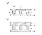
図2には、尾筒を形成する流路付き壁部材の部分断面図が示されている。
ガスタービン(図示せず)の燃焼器の尾筒50(図1参照)を形成する流路付き壁部材1としては、母材2と、複数の流路4が形成されている板材3とが用いられている。母材2と板材3は、ろう付によって張り合わせられている。ろう付によって張り合わせられることによって、母材2と板材3の間には、流路4が複数形成されることになる。
本実施形態の流路付き壁部材1の補修方法は、この流路付き壁部材1の板材3上に生じた損傷部(図示せず)を含む部材の一部分(以下「除去部分」という。)5を補修する。流路付き壁部材1の補修方法は、除去工程と、母材溶接工程と、流路形成工程と、板材溶接工程とを備えている。FIG. 2 shows a partial cross-sectional view of the wall member with a flow path forming the tail tube.
As the
The repair method for the wall member with
図3(a)に示すように、除去工程では、燃焼器の尾筒50(図1参照)を形成する流路付き壁部材1から損傷部を含む除去部分5を除去する。除去部分5の範囲は、流路付き壁部材1における損傷部の位置や損傷部の状態によって適宜決定される。 As shown to Fig.3 (a), in the removal process, the
図3(b)に示すように、母材溶接工程では、除去部分5(図3(a)参照)の大きさに加工した補修用母材6を既存の母材2に周溶接する。
補修用母材6は、厚さが1.6mmのニッケル基超合金が用いられる。補修用母材6および溶加剤としては、例えば、三菱マテリアル株式会社の商品名「トミロイ」、Special Metals Corporationの商品名「インコネル617」、Haynes Internationalの商品名「ハステロイX」等が好ましい。As shown in FIG. 3B, in the base metal welding step, the
The
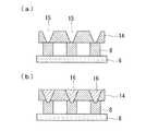
図3(c)に示すように、流路形成工程では、既存の母材2(図3(b)参照)に周溶接した補修用母材6上に溶接材粉末7を用いて複数の肉盛溶接が行われる。なお、図3(c)は、補修用母材6の部分拡大図である。複数の肉盛溶接を補修用母材6上に施工することによって、複数の肉盛溶接のビード8間には、流路4が形成される。 As shown in FIG. 3 (c), in the flow path forming step, a plurality of meats are formed by using
肉盛溶接は、例えば、YAGレーザ溶接(レーザ溶接)を用いている。肉盛溶接によって形成されるビード8は、ウィービングビード(以下「ビード」という。)である。なお、ビード8は、直線状のビードでもよい。ビード8は、例えば、厚さが3mmかつウィービング幅が2.5mmとなるように形成される。ビード8は、溶接により所定の形状に形成されるが、施工後の後加工を考慮して+1mm程度の余盛が設けられて形成されても良い。 For overlay welding, for example, YAG laser welding (laser welding) is used. The
肉盛溶接に用いられるYAGレーザ溶接の出力は、350Wから700Wが好ましい。レーザの出力が350W以下の場合には、溶着不良を生じ、700W以上の場合には、入熱が過多となって補修用母材6に熱変形や溶接割れが生じるためである。
また、溶接速度は、100mm/minから500mm/minが好ましい。溶接速度が100mm/minの場合には、入熱が過多となって補修用母材6に熱変形や溶接割れが生じ、500mm/min以上の場合には、溶接速度が速すぎるために融け残りが発生するためである。The output of YAG laser welding used for overlay welding is preferably 350 W to 700 W. This is because when the laser output is 350 W or less, poor welding occurs, and when it is 700 W or more, the heat input becomes excessive and thermal repair or weld cracking occurs in the
The welding speed is preferably 100 mm / min to 500 mm / min. When the welding speed is 100 mm / min, excessive heat input causes thermal deformation and weld cracks in the
溶接材粉末7には、補修用母材6と同じニッケル基超合金またはSpecial Metals Corporationの商品名「インコネル625」が好ましい。用いられる溶接材粉末の粒径は、125μmから500μmが好ましい。粉末供給量は、3g/minから15g/minによって送給される。粉末供給量が3g/min以下の場合には、ビード8の形成に時間がかかり、15g/min以上の場合には、粉末供給量過多のために溶着不良が生じるためである。 The
図3(d)に示すように、余盛が設けられているビード8を形成した場合には、ビード8を所定形状である厚さが2mmかつ幅が1.5mmになるように成型加工する。 As shown in FIG. 3D, when the
図3(e)に示すように、板材溶接工程では、例えば厚さ2mmの補修用板材9を複数の各ビード8の表面に溶接する。補修用板材9と各ビード8とは、YAGレーザ溶接によって貫通溶接12が行われる。レーザは、各ビード8の中央部を貫通するよう照射される。 As shown in FIG. 3 (e), in the plate material welding step, for example, a
以上の通り、本実施形態に係る流路付き壁部材の補修方法によれば、以下の作用効果を奏する。
補修用母材6上に肉盛溶接を行いビード8を複数設け、それらの肉盛溶接のビード8の表面に補修用板材9をYAGレーザ溶接(レーザ溶接)することとした。そのため、間隔が狭い流路4を有する流路付き壁部材1の補修をすることができる。したがって、流路付き壁部材1の補修コストを抑えることができる。As described above, according to the method for repairing a wall member with a flow path according to the present embodiment, the following effects are obtained.
Overlay welding was performed on the
溶接材粉末7を用いたYAGレーザ溶接によって肉盛溶接のビード8を形成することとした。そのため、幅の狭い細いビード8を施工することができる。したがって、補修用母材6上に間隔が狭い流路4を作成することができる。 The
なお、本実施形態では、溶接材粉末7を用いて形成されるビード8は、高さが2mmで幅が1.5mmに余盛分を付加するとして説明したが、本発明はこれに限定されるものではなく、尾筒50を形成する流路付き壁部材1の流路4を形成できる高さおよび幅であれば良い。
また、YAGレーザ溶接の代わりに電子ビームを用いた溶接でも良い。
また、補修用母材6の厚さについても、尾筒50を形成する流路付き壁部材1に適した厚みであれば良い。In the present embodiment, the
Further, welding using an electron beam may be used instead of YAG laser welding.
Further, the thickness of the
[第2実施形態]
以下、本発明の第2実施形態について説明する。本実施形態の流路付き壁部材の補修方法は、流路形成工程の補修用母材上に肉盛溶接を施工する前に補修用母材に管を設ける点で第1実施形態と相違し、その他は同様である。したがって、同一の流路付き壁部材の補修方法については、同一の符号を付してその説明を省略する。[Second Embodiment]
Hereinafter, a second embodiment of the present invention will be described. The method of repairing a wall member with a flow path according to the present embodiment is different from the first embodiment in that a pipe is provided on the repair base material before overlay welding is performed on the repair base material in the flow path forming step. Others are the same. Therefore, about the repair method of the wall member with the same flow path, the same code | symbol is attached | subjected and the description is abbreviate | omitted.
図4には、本発明の第2実施形態に係る流路付き壁部材の補修方法の説明図が示されている。
図4(a)に示すように、流路形成工程では、補修用母材6上に複数の冷却管(管)10を等間隔で設置する。冷却管10は、尾筒50(図1参照)を形成する流路付き壁部材1(図2参照)内に形成されている流路4と同様な形状の流路11を形成するものであり、例えば、高さが2mmかつ幅が1.5mmとされる。FIG. 4 shows an explanatory view of the repair method of the wall member with flow passage according to the second embodiment of the present invention.
As shown in FIG. 4A, in the flow path forming step, a plurality of cooling pipes (tubes) 10 are installed on the
図4(b)に示すように、補修用母材6上に等間隔で設置されている複数の冷却管10の間を肉盛溶接する。肉盛溶接は、溶接材粉末を用いてYAGレーザ溶接を施工する。肉盛溶接のビード8は、冷却管10の間を埋めるように冷却管10の高さと略同等となるまで施工される。 As shown in FIG. 4 (b), build-up welding is performed between a plurality of cooling
図4(c)に示すように、板材溶接工程では、冷却管10および肉盛溶接のビード8の表面に更に肉盛溶接(以下「空気面側肉盛溶接」という。)13が施工される。空気面側肉盛溶接13は、既存の流路付き壁部材1(図2参照)の表面と同じ高さになるように施工される。 As shown in FIG. 4C, in the plate material welding process, build-up welding (hereinafter referred to as “air surface side build-up welding”) 13 is further performed on the surfaces of the cooling
以上の通り、本実施形態に係る流路付き壁部材の補修方法によれば、以下の作用効果を奏する。
補修用母材6上に複数の冷却管(管)10を設けて、それらの冷却管10の間に肉盛溶接をすることとした。そのため、肉盛溶接のビード8の高さは、冷却管10の高さに合わせ、肉盛溶接のビード8の幅は、冷却管10と冷却管10との間隔に合わせて溶接することができる。したがって、肉盛溶接に要する時間を短縮することができる。As described above, according to the method for repairing a wall member with a flow path according to the present embodiment, the following effects are obtained.
A plurality of cooling pipes (tubes) 10 are provided on the
肉盛溶接のビード8の表面には、更に空気面側肉盛溶接(肉盛溶接)13を行うこととした。そのため、空気面側肉盛溶接13を任意の厚み、形状にすることができる。したがって、既存の流路付き壁部材1(図2参照)と形状を合わせることができる。 The
[第3実施形態]
以下、本発明の第3実施形態について説明する。本実施形態の流路付き壁部材の補修方法は、板材溶接工程において板材の反対面に肉盛溶接を施工する点で第1実施形態と相違し、その他は同様である。したがって、同一の流路付き壁部材の補修方法については、同一の符号を付してその説明を省略する。[Third Embodiment]
Hereinafter, a third embodiment of the present invention will be described. The repair method of the wall member with a flow path according to the present embodiment is different from the first embodiment in that build-up welding is performed on the opposite surface of the plate material in the plate material welding step, and the others are the same. Therefore, about the repair method of the wall member with the same flow path, the same code | symbol is attached | subjected and the description is abbreviate | omitted.
図5には、本発明の第3実施形態に係る流路付き壁部材の補修方法の説明図が示されている。
図5(a)に示すように、板材溶接工程では、例えば厚さが1mmの補修用板材9を複数形成されているビード8の表面に溶接する。補修用板材9と各ビード8とは、YAGレーザ溶接によって貫通溶接12が行われる。レーザは、各ビード8の中央部を貫通するよう照射される。FIG. 5 shows an explanatory view of the repair method of the wall member with flow passage according to the third embodiment of the present invention.
As shown in FIG. 5A, in the plate material welding step, for example, a
図5(b)に示すように、補修用板材9がビード8の表面に接している反対面には、空気側肉盛溶接(肉盛溶接)13が施工される。空気面側肉盛溶接13は、溶接材粉末を用いてYAGレーザ溶接によって施工される。空気面側肉盛溶接13は、既存の流路付き壁部材1(図2参照)の板材3と段差を生じないように滑らかに施工される。 As shown in FIG. 5 (b), air-side overlay welding (build-up welding) 13 is performed on the opposite surface where the
以上の通り、本実施形態に係る流路付き壁部材の補修方法によれば、以下の作用効果を奏する。
肉盛溶接の各ビード8の表面に溶接されている補修用板材9の反対面には、更に空気面側肉盛溶接(肉盛溶接)13を行うこととした。そのため、空気面側肉盛溶接13を施工した補修用板材9を任意の厚み、形状にすることができる。したがって、既存の流路付き壁部材1(図2参照)と形状を合わせることができる。As described above, according to the method for repairing a wall member with a flow path according to the present embodiment, the following effects are obtained.
On the opposite surface of the
[第4実施形態]
以下、本発明の第4実施形態について説明する。本実施形態の流路付き壁部材の補修方法は、複数の開先が設けられている板材を溶接する点で第1実施形態と相違し、その他は同様である。したがって、同一の流路付き壁部材の補修方法については、同一の符号を付してその説明を省略する。[Fourth embodiment]
The fourth embodiment of the present invention will be described below. The method for repairing a wall member with a flow path according to the present embodiment is different from the first embodiment in that a plate member provided with a plurality of grooves is welded, and the others are the same. Therefore, about the repair method of the wall member with the same flow path, the same code | symbol is attached | subjected and the description is abbreviate | omitted.
図6には、本発明の第4実施形態に係る流路付き壁部材の補修方法の説明図が示されている。
図6(a)に示すように、板材溶接工程において、例えば厚さが2mmの補修用板材14には、複数のスリット15が設けられている。補修用板材14に設けられているスリット15は、断面形状がV字形状となっている。スリット15は、補修用板材14が溶接されている各ビード8の表面と同じ間隔で複数形成されている。FIG. 6 is an explanatory view of the repair method for the wall member with flow passage according to the fourth embodiment of the present invention.
As shown in FIG. 6A, in the plate material welding step, for example, the
図6(b)に示すように、板材溶接工程において、複数のスリット15を有する補修用板材14を各ビード8の表面に溶接する。補修用板材14は、レーザ溶接によって開先溶接16が施工される。レーザは、補修用板材14に形成されている各スリット15の中央部と各ビード8の中央部とを貫通するように溶加材を加えながら照射される。 As shown in FIG. 6B, in the plate material welding step, the
以上の通り、本実施形態に係る流路付き壁部材の補修方法によれば、以下の作用効果を奏する。
開先(スリット)15を補修用板材14に設けることとした。そのため、補修用板材14を肉盛溶接の各ビード8の表面に開先溶接(溶接)16する際に、溶接を行う位置を目視することができる。したがって、溶接忘れを防止することができる。As described above, according to the method for repairing a wall member with a flow path according to the present embodiment, the following effects are obtained.
A groove (slit) 15 is provided on the
なお、本実施形態では、補修用板材14と各ビード8とをレーザを用いた開先溶接16によって溶着させるとして説明したが、本発明はこれに限定されるものではなく、TIG溶接やプラズマ溶接、また電子ビーム溶接によって施工しても良い。 In the present embodiment, the
1 流路付き壁部材
2 母材
3 板材
4 流路
6 補修用母材
8 ビード
9 補修用板材
DESCRIPTION OF
Claims (8)
Translated fromJapanese前記母材のうちの該除去工程にて除去されていない部分に補修用母材を周溶接する母材溶接工程と、
前記補修用母材上に複数の肉盛溶接を行い、複数のビードを形成する流路形成工程と、
前記複数のビードの間に流路が形成されるように、前記板材のうちの該除去工程にて除去されていない部分の表面と同じ高さの補修表面を形成する板材溶接工程と、
を備えた流路付き壁部材の補修方法。A removal step of removing a part of the wall member having a plurality of flow paths between the base material and the plate material;
A base material welding step ofcircumferentially welding a repair base material to a portion of the base materialthat has not been removed in the removal step;
A flow path forming step of performing aplurality of overlay weldings on the repair base material to form aplurality of beads ,
A plate material welding stepfor forming arepair surface having the same height as the surface of the portion of the plate materialthat has not been removed in the removal step so that a flow path is formed between the plurality of beads ,
A method for repairing a wall member with a flow path comprising:
前記板材溶接工程は、肉盛溶接することにより前記補修表面を形成する請求項1に記載の流路付き壁部材の補修方法。The flow path forming step includes providing a plurality of pipes on the repair base material before performing the plurality of build-up welds on the repair base material, and connecting the plurality of pipes by the build-up welding. Welded,
The plate welding process, method of repairing with flow passage wall member accordingto claim1 toform the repair surface by overlay welding.
Priority Applications (6)
| Application Number | Priority Date | Filing Date | Title |
|---|---|---|---|
| JP2010009990AJP5578864B2 (en) | 2010-01-20 | 2010-01-20 | Repair method of wall member with flow path |
| US13/511,498US9199342B2 (en) | 2010-01-20 | 2011-01-13 | Repairing method for wall member with flow passages |
| KR1020127013052AKR101306498B1 (en) | 2010-01-20 | 2011-01-13 | Method for repairing wall member with passage |
| EP11734564.5AEP2527077B1 (en) | 2010-01-20 | 2011-01-13 | Repairing method for wall member with flow passages |
| PCT/JP2011/050390WO2011089957A1 (en) | 2010-01-20 | 2011-01-13 | Method for repairing wall member with passage |
| CN201180004718.2ACN102630193B (en) | 2010-01-20 | 2011-01-13 | Repair method of wall member with flow path |
Applications Claiming Priority (1)
| Application Number | Priority Date | Filing Date | Title |
|---|---|---|---|
| JP2010009990AJP5578864B2 (en) | 2010-01-20 | 2010-01-20 | Repair method of wall member with flow path |
Publications (2)
| Publication Number | Publication Date |
|---|---|
| JP2011147952A JP2011147952A (en) | 2011-08-04 |
| JP5578864B2true JP5578864B2 (en) | 2014-08-27 |
Family
ID=44306759
Family Applications (1)
| Application Number | Title | Priority Date | Filing Date |
|---|---|---|---|
| JP2010009990AActiveJP5578864B2 (en) | 2010-01-20 | 2010-01-20 | Repair method of wall member with flow path |
Country Status (6)
| Country | Link |
|---|---|
| US (1) | US9199342B2 (en) |
| EP (1) | EP2527077B1 (en) |
| JP (1) | JP5578864B2 (en) |
| KR (1) | KR101306498B1 (en) |
| CN (1) | CN102630193B (en) |
| WO (1) | WO2011089957A1 (en) |
Families Citing this family (22)
| Publication number | Priority date | Publication date | Assignee | Title |
|---|---|---|---|---|
| US10314594B2 (en) | 2012-12-14 | 2019-06-11 | Corquest Medical, Inc. | Assembly and method for left atrial appendage occlusion |
| US10307167B2 (en) | 2012-12-14 | 2019-06-04 | Corquest Medical, Inc. | Assembly and method for left atrial appendage occlusion |
| US10813630B2 (en) | 2011-08-09 | 2020-10-27 | Corquest Medical, Inc. | Closure system for atrial wall |
| JP5456124B2 (en)* | 2012-07-04 | 2014-03-26 | 三菱重工業株式会社 | Method of welding erosion resistant metal material and turbine blade |
| US10662785B2 (en) | 2012-09-21 | 2020-05-26 | Mitsubishi Hitachi Power Systems, Ltd. | Method of welding erosion resistance metallic material and turbine blade |
| US20140142689A1 (en) | 2012-11-21 | 2014-05-22 | Didier De Canniere | Device and method of treating heart valve malfunction |
| US20160032766A1 (en)* | 2013-03-14 | 2016-02-04 | General Electric Company | Components with micro cooled laser deposited material layer and methods of manufacture |
| CN105143639B (en)* | 2013-04-09 | 2017-04-26 | 三菱重工业株式会社 | Method for repairing plate-shaped member, plate-shaped member, combustor, split ring, and gas turbine |
| US9366139B2 (en) | 2013-04-09 | 2016-06-14 | Mitsubishi Heavy Industries, Ltd. | Repair method of plate member, plate member, combustor, ring segment, and gas turbine |
| JP6043704B2 (en)* | 2013-09-19 | 2016-12-14 | 東京瓦斯株式会社 | Motor cooler and method for manufacturing motor cooler |
| US9377711B2 (en)* | 2013-09-30 | 2016-06-28 | Brother Kogyo Kabushiki Kaisha | Developing device, blade unit, and developing device manufacturing method |
| US9126279B2 (en)* | 2013-09-30 | 2015-09-08 | General Electric Company | Brazing method |
| JP2015069165A (en) | 2013-09-30 | 2015-04-13 | ブラザー工業株式会社 | Developing device, blade unit, and method of manufacturing developing device |
| JP2015069166A (en) | 2013-09-30 | 2015-04-13 | ブラザー工業株式会社 | Developing device, blade unit, and manufacturing method of developing device |
| US9566443B2 (en) | 2013-11-26 | 2017-02-14 | Corquest Medical, Inc. | System for treating heart valve malfunction including mitral regurgitation |
| WO2015104762A1 (en) | 2014-01-08 | 2015-07-16 | パナソニックIpマネジメント株式会社 | Laser welding method |
| JP6221906B2 (en) | 2014-03-31 | 2017-11-01 | ブラザー工業株式会社 | Developing device and manufacturing method of developing device |
| US10842626B2 (en) | 2014-12-09 | 2020-11-24 | Didier De Canniere | Intracardiac device to correct mitral regurgitation |
| NO344485B1 (en)* | 2016-12-15 | 2020-01-13 | Turbine Power Sl | Method for repairing crack damage in steel structures |
| CN109108568A (en)* | 2018-09-12 | 2019-01-01 | 新疆科鼎环保科技有限公司 | High pressure valve leakage position restorative procedure |
| US11517969B2 (en)* | 2019-01-24 | 2022-12-06 | General Electric Company | Weld-brazing techniques |
| JP6892542B1 (en)* | 2020-08-19 | 2021-06-23 | 株式会社神戸製鋼所 | Manufacturing method of modeled object and modeled object |
Family Cites Families (11)
| Publication number | Priority date | Publication date | Assignee | Title |
|---|---|---|---|---|
| JPS6192721A (en)* | 1984-10-15 | 1986-05-10 | Mitsubishi Heavy Ind Ltd | Production of cooling panel |
| GB2304306B (en) | 1994-05-26 | 1998-03-11 | Bgm | Work piece repair |
| US5933699A (en) | 1996-06-24 | 1999-08-03 | General Electric Company | Method of making double-walled turbine components from pre-consolidated assemblies |
| JP4110632B2 (en) | 1998-09-30 | 2008-07-02 | 松下電器産業株式会社 | Sealed battery |
| US6427327B1 (en) | 2000-11-29 | 2002-08-06 | General Electric Company | Method of modifying cooled turbine components |
| JP3915423B2 (en) | 2001-03-29 | 2007-05-16 | 株式会社日立製作所 | Gas turbine combustor liner structure and repair method |
| JP3581672B2 (en) | 2001-06-11 | 2004-10-27 | 三菱重工業株式会社 | Method for repairing plate-like body having flow path inside |
| US7216485B2 (en)* | 2004-09-03 | 2007-05-15 | General Electric Company | Adjusting airflow in turbine component by depositing overlay metallic coating |
| JP2006208227A (en) | 2005-01-28 | 2006-08-10 | Babcock Hitachi Kk | Repair method of nozzle of reactor pressure vessel |
| JP4936718B2 (en) | 2005-12-12 | 2012-05-23 | ミヤチテクノス株式会社 | Laser welding method |
| JP5260402B2 (en)* | 2009-04-30 | 2013-08-14 | 三菱重工業株式会社 | Plate-like body manufacturing method, plate-like body, gas turbine combustor, and gas turbine |
- 2010
- 2010-01-20JPJP2010009990Apatent/JP5578864B2/enactiveActive
- 2011
- 2011-01-13KRKR1020127013052Apatent/KR101306498B1/enactiveActive
- 2011-01-13EPEP11734564.5Apatent/EP2527077B1/enactiveActive
- 2011-01-13CNCN201180004718.2Apatent/CN102630193B/enactiveActive
- 2011-01-13WOPCT/JP2011/050390patent/WO2011089957A1/enactiveApplication Filing
- 2011-01-13USUS13/511,498patent/US9199342B2/enactiveActive
Also Published As
| Publication number | Publication date |
|---|---|
| WO2011089957A1 (en) | 2011-07-28 |
| JP2011147952A (en) | 2011-08-04 |
| CN102630193A (en) | 2012-08-08 |
| EP2527077A4 (en) | 2013-06-19 |
| EP2527077A1 (en) | 2012-11-28 |
| CN102630193B (en) | 2015-02-04 |
| US20120272611A1 (en) | 2012-11-01 |
| EP2527077B1 (en) | 2015-03-18 |
| KR101306498B1 (en) | 2013-09-09 |
| KR20120083494A (en) | 2012-07-25 |
| US9199342B2 (en) | 2015-12-01 |
Similar Documents
| Publication | Publication Date | Title |
|---|---|---|
| JP5578864B2 (en) | Repair method of wall member with flow path | |
| JP5322371B2 (en) | How to repair a disk with an integrated blade, test piece at the start and end of work | |
| JP5383968B2 (en) | Shim-based laser beam welding method for joining superalloys applied to gas turbines | |
| EP2950972B1 (en) | Localized repair of supperalloy component | |
| US7802350B2 (en) | Flange hole repair | |
| JP2008110404A (en) | Method and apparatus for repairing aperture and adjacent defect in flange | |
| JP2011051017A (en) | Laser weld repair method for combustion cap effusion plate | |
| JP2005297066A (en) | Welding method | |
| JP6581498B2 (en) | Turbine rotor disk repair method | |
| CN105246644A (en) | Partial Repair of Superalloy Components | |
| CN104096984A (en) | Method for welding rotors for power generation | |
| CN109759789A (en) | The thrust chamber pressure resistance interlayer manufacturing method of liquid-propellant rocket engine | |
| JP5535799B2 (en) | Repair method of metal parts and repaired metal parts | |
| JP4915251B2 (en) | Clad welded structure of low alloy steel base metal | |
| JP6386330B2 (en) | Repair method for defective welds in metal cask welded structures | |
| JP6322561B2 (en) | Temporary welding construction method for metal cask welded structure and metal cask with heat transfer fin | |
| WO2015112473A1 (en) | Additive repair for combustor liner panels | |
| JP5395392B2 (en) | How to retouch metal parts | |
| JP6370557B2 (en) | Overlay welding method | |
| JP2016098817A (en) | Modified bucket platforms of turbine buckets and methods for modifying bucket platforms of turbine buckets | |
| JP5959849B2 (en) | Laser overlay welding method | |
| Steckowicz et al. | Development and implementation of robotized wire arc additive repair of a gas turbine diaphragm | |
| JP2012229639A (en) | Method for repairing turbine high-temperature component, gas turbine moving blade and gas turbine | |
| US20190084044A1 (en) | Method of joining members and turbine component | |
| JP7524200B2 (en) | Welding and brazing techniques |
Legal Events
| Date | Code | Title | Description |
|---|---|---|---|
| A621 | Written request for application examination | Free format text:JAPANESE INTERMEDIATE CODE: A621 Effective date:20130109 | |
| A131 | Notification of reasons for refusal | Free format text:JAPANESE INTERMEDIATE CODE: A131 Effective date:20131112 | |
| A521 | Request for written amendment filed | Free format text:JAPANESE INTERMEDIATE CODE: A523 Effective date:20140114 | |
| TRDD | Decision of grant or rejection written | ||
| A01 | Written decision to grant a patent or to grant a registration (utility model) | Free format text:JAPANESE INTERMEDIATE CODE: A01 Effective date:20140610 | |
| A61 | First payment of annual fees (during grant procedure) | Free format text:JAPANESE INTERMEDIATE CODE: A61 Effective date:20140708 | |
| R151 | Written notification of patent or utility model registration | Ref document number:5578864 Country of ref document:JP Free format text:JAPANESE INTERMEDIATE CODE: R151 | |
| S111 | Request for change of ownership or part of ownership | Free format text:JAPANESE INTERMEDIATE CODE: R313111 | |
| R350 | Written notification of registration of transfer | Free format text:JAPANESE INTERMEDIATE CODE: R350 | |
| R250 | Receipt of annual fees | Free format text:JAPANESE INTERMEDIATE CODE: R250 | |
| S533 | Written request for registration of change of name | Free format text:JAPANESE INTERMEDIATE CODE: R313533 | |
| R350 | Written notification of registration of transfer | Free format text:JAPANESE INTERMEDIATE CODE: R350 |