JP5578313B2 - Audio output device - Google Patents
Audio output deviceDownload PDFInfo
- Publication number
- JP5578313B2 JP5578313B2JP2010050663AJP2010050663AJP5578313B2JP 5578313 B2JP5578313 B2JP 5578313B2JP 2010050663 AJP2010050663 AJP 2010050663AJP 2010050663 AJP2010050663 AJP 2010050663AJP 5578313 B2JP5578313 B2JP 5578313B2
- Authority
- JP
- Japan
- Prior art keywords
- sound
- air chamber
- output device
- front air
- housing
- Prior art date
- Legal status (The legal status is an assumption and is not a legal conclusion. Google has not performed a legal analysis and makes no representation as to the accuracy of the status listed.)
- Expired - Fee Related
Links
Images


Landscapes
- Details Of Audible-Bandwidth Transducers (AREA)
- Circuit For Audible Band Transducer (AREA)
Description
Translated fromJapanese本発明は、音声出力装置に関する。 The present invention relates to an audio output device.
携帯電話端末などの音声出力装置は、筐体、及びスピーカ(鳴動機構)を有している。スピーカは、筐体の内部に配置される。筐体には、スピーカで発せられた音声が外部に放出されるように、音孔が設けられる。 An audio output device such as a mobile phone terminal has a housing and a speaker (sounding mechanism). The speaker is disposed inside the housing. The housing is provided with a sound hole so that sound emitted from the speaker is emitted to the outside.
音孔を介して、筐体の内部に水が浸入してしまうことがある。水の浸入により、スピーカよって所望する音声を出力することが困難になる場合がある。筐体内に浸入した水を取り除くためには、例えば、音声出力装置を振り回したり、水が蒸発するのをまつしかない。一度筐体内に入り込んだ水は、なかなか取り除くことが難しい。 Water may enter the inside of the housing through the sound hole. Intrusion of water may make it difficult to output a desired sound through a speaker. In order to remove the water that has entered the housing, for example, the sound output device can be swung around or the water can be evaporated. Once water has entered the housing, it is difficult to remove it.
関連技術が、特許文献1(特開2008−167097)に記載されている。特許文献1には、第1の筐体と第2の筐体とが折り畳まれる構造の電子機器において、第1の筐体に、閉状態で第2の筐体と対向するような位置にレシーバ音孔を設ける点と、第1の筐体に、第1の筐体内に停留した液体をレシーバ音孔に流入した空気によって流出させるためのレシーバサブ音孔を設ける点とが開示されている。 Related technology is described in Japanese Patent Application Laid-Open No. 2008-167097. In
他の関連技術が、特許文献2(特開2000−201388)に記載されている。特許文献2には、筐体の内部に設けられた電気信号/音響変換器と、筐体を内外に貫通して設けられた通音孔と、電気信号/音響変換器と通音孔とを連通させる導音部とを備えた電子機器の電気信号/音響変換部の構造であって、通音孔の筐体の内部側の端部の少なくとも一部が、導音部の隅部に位置すること、を特徴とする、電子機器の電気信号/音響変換部の構造が記載されている。特許文献2の記載によれば、導音部の内部に侵入してしまった異物が滞留しがちな隅部から通音孔を通して異物を外部に排出できる。 Another related technique is described in Patent Document 2 (Japanese Patent Laid-Open No. 2000-201388).
更に他の関連技術が、特許文献3(特開2007−67897)に記載されている。特許文献3には、スピーカグリル後方の内蔵スピーカと接続した出力アンプの印加電圧を、音声信号出力時より高くしたのち、アンプに音声信号に代えて低周波の連続した信号を入力し、その出力でもってスピーカを振動させて、スピーカグリル内の侵入水を排水するようにした携帯型無線通信機が開示されている。特許文献3には、横方向に形成されたスリット状のものを複数本並列に設ける点、各スリットは斜め下方向へ向けて開口させた構造となっている点が記載されている。 Still another related technique is described in Patent Document 3 (Japanese Unexamined Patent Application Publication No. 2007-67897). In
また、更に他の関連技術として、特許文献4(特開2000−138987)には、スピーカの振動板に撥水塗料を塗布した防水スピーカが開示されている。 As still another related technique, Patent Document 4 (Japanese Patent Laid-Open No. 2000-138987) discloses a waterproof speaker in which a water-repellent paint is applied to a diaphragm of the speaker.
特許文献2に記載されるように、隅部に通音孔を設けることにより、異物を排出しやすくなると考えられる。しかし、筐体内に水が浸入した場合には、水が導音部の中央部分に留まってしまい、排水され難くなってしまう。 As described in
また、排水能力を高めるために、音孔の面積を大きくすることが考えられる。しかしながら、音孔の面積を大きくすると、逆に水が浸入しやすくなってしまう。また、音孔の面積を大きくすると、音響共振点における音圧が小さくなり、良好な音響特性が得られ難くなる、という問題点があった。 In order to increase the drainage capacity, it is conceivable to increase the area of the sound hole. However, if the area of the sound hole is increased, water easily enters. Further, when the area of the sound hole is increased, the sound pressure at the acoustic resonance point is decreased, and it is difficult to obtain good acoustic characteristics.
本発明に係る音声出力装置は、筐体と、通話用のマイク部及びレシーバ部と、鳴動機構と、前気室と、音孔群と、制御機構とを具備する。マイク部及びレシーバ部は、筐体の前面に配置される。鳴動機構は、マイク部及びレシーバ部が配置された前面とは反対側の背面の筐体内に配置され、振動板を有する。鳴動機構は、振動板を振動させることにより鳴動する。前気室は、振動板と筐体の内面との間に形成される。音孔群は、筐体に形成され、前気室を筐体の外部と連通させる。制御機構は、鳴動機構の動作を制御する。制御機構は、振動板の振動によって前気室に侵入した水分が音孔群を介して排水されるように、可聴域よりも低い周波数帯域で振動するように鳴動機構を鳴動させる。筐体は、前気室の中央部に対応する中央部分と、前気室の外周部に対応する外周部分と、中央部分と外周部分との間に形成される中間部分とを有する。音孔群は、中間部分に設けられた中間音孔群を有している。The audio output device according to the present invention includes acasing, a microphone unit and a receiver unit for a call, a ringing mechanism, a front air chamber, a sound hole group, and a control mechanism. The microphone unit and the receiver unit are disposed on the front surface of the housing. The ringing mechanism is disposed in a housing on the back side opposite to the front surface on which the microphone unit and the receiver unit are disposed, and has a diaphragm. The ringing mechanism rings by vibrating the diaphragm. The front air chamber is formed between the diaphragm and the inner surface of the housing. The sound hole group is formed in the casing and communicates the front air chamber with the outside of the casing. The control mechanism controls the operation of the ringing mechanism. The control mechanism sounds the sounding mechanism so as to vibrate in a frequency band lower than the audible range so that moisture that has entered the front air chamber due to vibration of the diaphragm is drained through the sound hole group. The housing includes a central portion corresponding to the central portion of the front air chamber, an outer peripheral portion corresponding to the outer peripheral portion of the front air chamber, and an intermediate portion formed between the central portion and the outer peripheral portion. The sound hole group has an intermediate sound hole group provided in an intermediate portion.
本発明によれば、排水性能を高めた上、良好な音響特性を得ることのできる、音声出力装置が提供される。 ADVANTAGE OF THE INVENTION According to this invention, while improving drainage performance, the audio | voice output apparatus which can acquire a favorable acoustic characteristic is provided.
以下に、図面を参照しつつ、本発明の実施形態について説明する。 Hereinafter, embodiments of the present invention will be described with reference to the drawings.
(第1の実施形態)
図1Aは、本実施形態に係る音声出力装置を示す概略図である。本実施形態では、音声出力装置として、折り畳み型の携帯電話端末1について説明する。図1Aには、開状態における携帯電話端末1が示されている。(First embodiment)
FIG. 1A is a schematic diagram illustrating an audio output device according to the present embodiment. In this embodiment, a foldable
図1Aに示されるように、携帯電話端末1は、第1筐体2、及び第2筐体3を備えている。第1筐体2と第2筐体3とは、折り畳み可能になるように、連結されている。 As shown in FIG. 1A, the
第1筐体2には、レシーバ部4及び表示部5が設けられている。レシーバ部4は、通話時に、通話相手の音声を出力するために設けられている。ユーザは、通話時に、レシーバ部4に耳をあてることにより、通話相手の音声を聞くことができる。表示部5は、ユーザに対して必要な情報を表示する部分である。表示部5には、文字、記号、及び図形等の情報が表示される。 The
第2筐体3には、キー操作部4、及びマイク部6が設けられている。キー操作部4は、ユーザが携帯電話端末1を操作するために用いる部分である。ユーザは、キー操作部4を用いて、ダイヤル情報の入力、及び各種設定情報の入力などを行うことができる。マイク部5は、通話時に、ユーザの音声を通話相手に伝えるために設けられている。マイク部5は、ユーザの音声を集音し、電気信号に変換する。電気信号は、通話相手側の装置へ送信される。 The
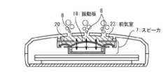
図1Bは、閉状態における携帯電話端末1を示す概略図である。図1Bに示されるように、第1筐体2の内部には、鳴動機構として、スピーカ7が配置されている。そして、第1筐体2には、スピーカ7で発せられた音声を外部に放出するために、音孔群8が設けられている。尚、スピーカ7と第1筐体2の内壁との間には、後述する前気室が形成されている。着信時、メロディのダウンロード時、およびハンズフリー機能の使用時等においては、スピーカ7が可聴音を発する。発せられた可聴音は、前気室から音孔群8を通じて外部に放射される。これにより、ユーザは、着信の存在を知ったり、所望する音楽を聞くことができる。 FIG. 1B is a schematic diagram showing the
ここで、音孔群8は、中間音孔群8−1と、中央音孔8−2とを備えている。中央音孔8−2は、前気室の中央部に面する位置に設けられている。尚、中央部は、前気室の重心に対応する部分であるものとする。 Here, the
一方、中間音孔群8−1は、中間部分に設けられている。中間部分は、中央部分と外周部分との間に形成される部分である。中央部分とは、前気室の中央部に面する部分であり、外周部分とは、前気室の外周部に対応する部分である。そして、中間音孔群8−1は、複数の中間音孔を有している。複数の中間音孔は、中央音孔8−2を中心とする円周に沿って、並んでいる。 On the other hand, the intermediate sound hole group 8-1 is provided in the intermediate portion. The intermediate portion is a portion formed between the central portion and the outer peripheral portion. The central portion is a portion facing the central portion of the front air chamber, and the outer peripheral portion is a portion corresponding to the outer peripheral portion of the front air chamber. The intermediate sound hole group 8-1 has a plurality of intermediate sound holes. The plurality of intermediate sound holes are arranged along a circumference centered on the central sound hole 8-2.
次いで、第1筐体2の内部構成について説明する。 Next, the internal configuration of the
図2は、図1BのAA断面を示す断面図であり、第1筐体2の断面を示している。図2に示されるように、第1筐体2は、前面及び背面を有している。前面は、閉状態において第2筐体3と対向する面であり、背面は、閉状態において外側を向く面である。図2に示されるように、第1筐体2の内部には、基板10、及びスピーカ7が配置されている。また、第1筐体2の前面には、表示部5が嵌め込まれている。 FIG. 2 is a cross-sectional view showing the AA cross section of FIG. 1B, and shows a cross section of the
表示部5は、正面液晶11、及びスクリーン9を有している。正面液晶11は、文字、記号、及び図形等を映し出すLCD(Liquid Crystal Display)やバックライトなどを含んでいる。スクリーン9は、透明材料により形成され、正面液晶11の表面を保護している。 The
スピーカ7は、フレーム17、プロテクタ20、振動板18、ボイスコイル16、ヨーク14、及び磁石15を備えている。ここで、第1筐体2の背面における内壁には、フレーム17に対応する形状のリブ22が形成されている。リブ22は、内壁から、第1筐体2の内部に向かって突き出ている。リブ22の高さは、例えば、0.5〜1.0mm程度である。リブ22の先端部には、クッション21(弾性部材)を介して、プロテクタ20が取り付けられている。プロテクタ20は、振動板18を保護するために設けられており、クッション21とフレーム17とによって挟まれている。フレーム17は、振動板18及びヨーク14を支持するために設けられている。ヨーク14は、フレーム17の底面から、前面側に向かって突き出るように、配置されている。ヨーク14上には、背面側に、磁石15が配置されている。振動板18は、磁石15及びヨーク14の背面側に配置されている。ボイスコイル16は、振動板18に連結されており、ヨーク14および磁石15によって形成される磁界内に位置している。このスピーカ7では、ボイスコイル16に正負の電流が流れると、ヨーク14及び磁石15により形成される磁界によってボイスコイル16が変位する。その結果、振動板18が振動し、音声が出力される。 The
ここで、振動板18の表面は、フッ素樹脂の塗布などにより、撥水加工が施されていることが好ましい。振動板18の表面が撥水性を有していることにより、振動板18が振動したときに、前気室23内の水がはじかれ易くなり、排水され易くなる。 Here, it is preferable that the surface of the
また、スピーカ7は、防水構造が形成されるように、構成されている。具体的には、スピーカ7は、第1筐体2の内部を、前気室23と内部空間19とに分けるように、配置されている。前気室23は、振動板18と第1筐体2の内壁との間に形成される空間である。フレーム17及びプロテクタ20は、前気室23に侵入した水が内部領域19側へ漏れないように、クッション21を介して第1筐体2の内壁に連結されている。また、クッション21は、前気室23に侵入した水が内部領域19側へ漏れないように、十分に圧縮されて配置されている。振動板18の外周部も、前気室23に侵入した水が内部領域19側へ漏れないように、全周でフレーム17に連結されている。 The
次いで、基板10について説明する。基板10は、内部領域19に配置されている。図2には描かれていないが、基板10上には、携帯電話端末1の各種機能(排水機能、メロディ鳴動、発着呼、メール送受信など)を実現するための制御部品(DSP(Digital Signal Processor)、CSP(Chip Scale Package)、音源IC、D/A変換器、アンプ、抵抗、コンデンサなど)が実装されている。 Next, the substrate 10 will be described. The substrate 10 is disposed in the
ここで、基板10上には、スピーカ7の動作を制御する制御機構が実装されている。図3は、制御機構を概略的に示すブロック図である。図3に示されるように、制御機構は、制御部27、音源IC24、D/A変換器12、及びSPKアンプ13を有している。音源IC24は、音源情報を格納している。制御部27は、図示しないROM(Read Only Memory)に格納された制御プログラムがCPUにより実行されることで、実現される。制御部27は、音源IC24に格納される音源情報に基づいて、鳴動信号を生成する。鳴動信号は、D/A変換器12によってアナログ信号に変換され、SPKアンプ13によって増幅された後、スピーカ7に供給される。スピーカ7では、鳴動信号に応じてボイスコイル16に電流が流れ、振動板18が振動する。 Here, a control mechanism for controlling the operation of the
音源情報は、及びユーザに音声を聞かせるために用いられる可聴音用音源情報と、排水のために用いられる排水用音源情報とを含んでいる。可聴音用音源情報が制御部27によって選択された場合には、鳴動信号として、可聴音用信号がスピーカ7に供給される。この場合、スピーカ7は、可聴音を発する。その可聴音としては、例えば、電源が入れたときに発生される起動音、着信音、ミュージック再生音、カメラのシャッター音、開閉合図音、及びハンズフリー通話時における通話音などが挙げられる。一方、排水用音源情報が制御部27によって選択された場合には、鳴動信号として、排水用信号がスピーカ7に供給される。この場合、スピーカ7では、振動板18が、前気室23に侵入した水が排水されるように、振動する。 The sound source information includes audible sound source information used for letting the user hear the sound and drainage sound source information used for drainage. When the audible sound source information is selected by the
排水用音源情報としては、例えば、振動板18が共振周波数で振動するような情報、及び振動板18が可聴周波数よりも低い周波数(例えば100Hz)で振動するような情報などが好適に用いられる。振動板18が共振周波数で振動すれば、振動振幅を最大にすることができ、前気室23内の水が速やかに排水される。振動板18が可聴周波数よりも低い周波数で振動すれば、ユーザまたは周囲の人に水抜きをしている事を気付かれることなく、排水を行うことが可能になる。また、排水用音源情報として、振動板18の振動周波数が、予め設定された周波数帯域内で時間と共に変化するような情報を用いることも好ましい。高い排水効果を得ることのできる周波数は、音孔群8の面積や前気室23の容積により、異なると考えられる。振動板18の振動周波数を変動させることにより、排水に有効な周波数帯を網羅することが可能になる。 As the drainage sound source information, for example, information such that the
次いで、本実施形態に係る音声出力装置の動作方法について説明する。図4は、音声出力装置の排水時における動作方法を示すフローチャートである。 Next, an operation method of the audio output device according to the present embodiment will be described. FIG. 4 is a flowchart showing an operation method of the audio output device during drainage.
ステップS−1:
携帯電話端末1が、水に濡れたとする。この場合、音孔8を介して、前気室23に水が浸入することがある。このような場合、ユーザは、キー操作部4を用いて、排水指示を携帯電話端末1に入力する。携帯電話端末1では、制御部27が、排水指示が入力されたか否かを判定している。排水指示を受け付けた場合、制御部27は、次のステップS−2の動作を行う。Step S-1:
It is assumed that the
ステップS−2:
排水指示を受け付けた場合、制御部27は、音源IC24から排水用音源情報を選択し、鳴動信号として排水用信号を生成する。これにより、スピーカ7では、振動板18が振動する。図5は、振動板18が振動した際の様子を概略的に示す断面図である。図5に示されるように、振動板18の振動により、前気室23に侵入した水は、音孔群8を介して外部へ排出される。Step S-2:
When the drainage instruction is received, the
ステップS−3:
その後、ユーザが排水停止指示を携帯電話端末1に入力すると、制御部27はスピーカ7の動作を停止させる。尚、制御部27は、予め設定された時間が経過したときに、自動的にスピーカ7の動作を停止させてもよい。Step S-3:
Thereafter, when the user inputs a drainage stop instruction to the
ここで、本実施形態によれば、中間音孔群8−1が設けられているために、排水性能が高められている。中間音孔群8−1は、既述のように、前気室23の中央部と、前気室23の外周部との間に対応する位置に、設けられている。前気室23の外周部に対応する位置に音孔が設けられている場合には、前気室23の中央部分に水が滞留しやすくなる。一方、前気室23の中央部分にのみ音孔が設けられている場合には、前気室23の外周部に水が滞留しやすくなる。これに対して、本実施形態では、中間音孔群8−1が設けられていることにより、前気室23の外周部に存在する水が、中間音孔群8−1を介して排水されやすくなる。また、前気室23の中央部に存在する水は、中央音孔8−2により、排水される。すなわち、本実施形態によれば、前気室23のどの部分に水が存在していても、容易に排水を行うことが可能になる。前気室23に水が溜まっている場合には、スピーカ7が可聴音を発生させたときに、振動板18の振動が抑制され、発せられる可聴音の音圧が極端に小さくなってしまう。これに対して、本実施形態によれば、容易に排水を行うことが可能となるので、可聴音の音圧の低下を防止することが可能になる。 Here, according to this embodiment, since the middle sound hole group 8-1 is provided, the drainage performance is enhanced. As described above, the intermediate sound hole group 8-1 is provided at a position corresponding to between the central portion of the
また、本実施形態では、中央音孔8−1を中心とする円周に沿って、複数の中間音孔が並べられている。このようなレイアウトを採用することにより、前気室23のどの部分に水が存在していても、容易に排水を行うことが可能になる。 In the present embodiment, a plurality of intermediate sound holes are arranged along a circumference centered on the central sound hole 8-1. By adopting such a layout, it becomes possible to easily drain water regardless of the portion of the
また、本実施形態では、排水効率が高められる結果、音孔群8の面積を小さくすることが可能になる。その結果、音響共振点における音圧の低下を最小限に抑えることができる。そのため、スピーカ7が可聴音を出力する場合における音響特性を良好な状態に維持することができる。 Moreover, in this embodiment, as a result of improving drainage efficiency, it becomes possible to make the area of the
また、音孔群8の面積は、排水効果が最大限に発揮されるような面積に調整されていることが好ましい。そのような面積は、振動板18の振動威力や前気室23の容積に基づいて、調整することができる。例えば、特許文献3(特開2007−67897)に記載されるように、音声信号出力時より高い電圧を出力アンプに印加した場合には、スピーカに過電圧による負担が加わり、故障の原因になることがある。これに対して、音孔群8の面積を調整することにより、排水用信号として、可聴音用信号よりも最大電圧が高い信号を、特別にスピーカ7に加える必要がなくなる。その結果、スピーカ7に過電圧による負担が加わらず、スピーカ7が故障する可能性を低くすることができる。 Moreover, it is preferable that the area of the
尚、本実施形態では、ユーザから与えられる排水指示に応じて排水動作が行われる場合について説明した。但し、排水動作は、必ずしも、ユーザによって与えられる排水指示に応じて実行される必要はない。この点について、変形例を用いて、説明する。 In the present embodiment, the case where the drainage operation is performed according to the drainage instruction given by the user has been described. However, the draining operation does not necessarily have to be executed according to the draining instruction given by the user. This point will be described using a modification.
図6は、本実施形態の変形例に係る音声出力装置の動作方法を示すフローチャートである。この変形例に係る音声出力装置では、制御部27の動作が変更されている。その他の構成及び動作については、本実施形態と同様であるものとする。 FIG. 6 is a flowchart showing an operation method of the audio output device according to the modification of the present embodiment. In the audio output device according to this modification, the operation of the
ステップS−4:
着信時や、アラーム発生時などにおいては、制御部27に対して、可聴音を発生させる旨を示す指示が与えられる。Step S-4:
When a call is received or an alarm is generated, an instruction indicating that an audible sound is generated is given to the
ステップS−5:
可聴音の発生指示を受け付けると、制御部27は、音源情報から排水用音源情報を選択する。これにより、鳴動信号として排水用信号をスピーカ7に供給される。その結果、スピーカ7において振動板18が振動し、前気室23に存在する水が排水される。排水用信号は、所定の時間(例えば5秒間)、供給される。Step S-5:
When receiving an audible sound generation instruction, the
ステップS−6:
排水用信号が5秒間供給された後、制御部27は、音源情報から可聴音用音源情報を選択する。これにより、鳴動信号として、可聴音用信号がスピーカ7に供給される。その結果、スピーカ7から可聴音が発せられ、ユーザはスピーカ7が発した音を聞くことができる。Step S-6:
After the drainage signal is supplied for 5 seconds, the
ステップS−7:
その後、可聴音の停止指示が制御部27に与えられると、制御部27は、可聴音信号の供給を停止し、処理を終了する。Step S-7:
Thereafter, when an instruction to stop the audible sound is given to the
上述の変形例の動作によれば、排水処理が、可聴音を発生させる際の前動作として行われる。そのため、ユーザは、排水処理を行うために特別な操作をする必要がなく、利便性を向上させることができる。 According to the operation of the above-described modified example, the drainage treatment is performed as a pre-operation when generating an audible sound. Therefore, the user does not need to perform a special operation to perform the wastewater treatment, and convenience can be improved.
以上説明したように、本実施形態によれば、音孔群8のレイアウトが工夫されていることにより、効率よく排水を行うことが可能になる。 As described above, according to this embodiment, the layout of the
尚、本実施形態では、制御部27が、可聴音用信号をスピーカ7に供給するタイミングとは別のタイミングで、排水用信号をスピーカ7に供給する。但し、制御部27が、可聴音信号に排水用信号を重畳させてスピーカ7に供給するように、構成されていてもよい。 In the present embodiment, the
また、本実施形態では、第1筐体2にリブ22が設けられている場合について説明した(図2参照)。但し、前気室23の水が内部空間19側に漏洩しないように、スピーカ7が第1筐体2に支持されていれば、リブ22は必ずしも設けられている必要はない。例えば、スピーカ7と第1筐体2の内壁とを、両面テープやクッションを介して密着させることにより、前気室23が形成されてもよい。 Moreover, in this embodiment, the case where the
また、本実施形態では、プロテクタ20が設けられている場合について説明した(図2参照)。ただし、プロテクタ20は必ずしも設けられている必要はなく、スピーカ7の実装位置や条件によっては、プロテクタ20が設けられていなくてもよい。 Moreover, in this embodiment, the case where the
また、本実施形態では、鳴動機構として、スピーカ7が用いられる場合について説明した。但し、鳴動機構としてはスピーカ7に限定されるものではない。例えば、鳴動機構として、固定電話機、ビデオカメラ、デジタルカメラ、PHS、ICレコーダ、レシーバ、圧電スピーカ、音楽再生プレイヤー、及び複合部品などが用いられてもよい。 Moreover, in this embodiment, the case where the
また、本実施形態では、音声出力装置として、折り畳み型の携帯電話端末が用いられる場合について説明した。但し、音声出力装置は、鳴動機構が実装されている装置であればよく、折り畳み型の携帯電話端末に限定されるものではない。例えば、音声出力装置として、一体型の携帯電話端末、スライド式の携帯電話端末、ページャ、PHS、音楽再生プレイヤー、デジタルカメラなどを用いることも可能である。 In the present embodiment, the case where a foldable mobile phone terminal is used as the audio output device has been described. However, the audio output device is not limited to a foldable mobile phone terminal as long as the sound output mechanism is mounted. For example, an integrated mobile phone terminal, a sliding mobile phone terminal, a pager, a PHS, a music playback player, a digital camera, or the like can be used as the audio output device.
また、本実施形態では、音声出力装置1に防水構造が形成されている場合について説明した。すなわち、前気室23内の水が内部空間19側に漏れないように、スピーカ7が取り付けられている場合について説明した。但し、音声出力装置1に防水構造が形成されていない場合であっても、本発明は適用可能である。この場合、水濡れによる電子部品のショートを回避するため、音声出力装置1の電源がオフにされる。そして、水が乾くのを待った後、電源が入れられる。ここで、電源を入れたタイミングで、排水用信号がスピーカ7に供給されれば、前気室23に溜まってしまった水を排出することができ、元の良好な音響特性に戻すことが可能となる。 Moreover, in this embodiment, the case where the waterproof structure was formed in the audio |
また、本実施形態では、中間音孔群8−1が、中央音孔8−2を中心とする円周に沿って配置されている場合について説明した。但し、中間音孔群8−1は、必ずしもその円周の全周に沿って配置されている必要はなく、デザイン上は位置が難しい場合には、円周上の一部に設けられていてもよい。この場合であっても、振動板の振動により、音孔が設けられていない部分に溜まった水が、中央音孔8−2または中間音孔群8−1を介して、排水され易くなる。 Moreover, in this embodiment, the case where the intermediate sound hole group 8-1 was arrange | positioned along the periphery centering on the central sound hole 8-2 was demonstrated. However, the intermediate sound hole group 8-1 does not necessarily have to be arranged along the entire circumference of the circumference. If the position is difficult on the design, it is provided on a part of the circumference. Also good. Even in this case, the water accumulated in the portion where no sound hole is provided due to the vibration of the diaphragm is easily drained through the central sound hole 8-2 or the intermediate sound hole group 8-1.
(第2の実施形態)
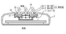
続いて、第2の実施形態について説明する。図7は、本実施形態にかかる音声出力装置1を示す概略断面図である。本実施形態では、第1の実施形態に対して、防塵メッシュ部材25が追加されている。その他の点については、第1の実施形態と同様の構成を採用することができるので、詳細な説明は省略する。(Second Embodiment)
Next, the second embodiment will be described. FIG. 7 is a schematic cross-sectional view showing the
図7に示されるように、防塵メッシュ部材25は、前気室23に設けられている。防塵メッシュ部材25は、振動板18よりも背面側に設けられており、前気室23を第1室23−1と第2室23−2とに分割している。第1室23−1は、防塵メッシュ部材25よりも背面側に形成される空間であり、第2室23−2は、防塵メッシュ部材25よりも前面側に形成される空間である。防塵メッシュ部材25の端部は、リブ22とクッション部材21とによって挟まれている。また、防塵メッシュ部材15には、撥水加工が施されている。 As shown in FIG. 7, the
本実施形態によれば、防塵メッシュ部材25により、音孔群8から第1室23−1内に侵入した埃などの異物が、第2室23−2側へ侵入することが防止される。また、防塵メッシュ部材25に撥水加工が施されていることにより、第2室23−2側へ水が浸入することが、ある程度防止される。 According to the present embodiment, the dust-
本実施形態では、音声出力装置1が水没した場合、第1室23−1に水が溜まることになる。本実施形態においても、制御部27によって排水用信号がスピーカ7に供給されると、振動板18が振動する。振動板18の振動により、防塵メッシュ部材25も空気振動により振動する。その結果、第1室23−1に溜まった水が、防塵メッシュ部材25により弾かれ、音孔群18を介して外部へ排出される。尚、この際、防塵メッシュ部材25がその共振周波数で振動するように、排水用信号がスピーカ7に供給されることが好ましい。 In the present embodiment, when the
尚、本実施形態では、防塵メッシュ部材15の端部が、クッション21とリブ22に挟まれている場合について説明した。ただし、防塵メッシュ部材15は、埃などの異物が第2室23−2側へ侵入することが防止されるように配置されていればよい。例えば、防塵メッシュ部材15は、プロテクタ20に貼り付けられていてもよい。 In the present embodiment, the case where the end of the dustproof mesh member 15 is sandwiched between the
(第3の実施形態)
次いで、第3の実施形態について説明する。図8は、本実施形態に係る音声出力装置を示す概略断面図である。本実施形態では、第2の実施形態における防塵メッシュ部材25が、防水シート26に変更されている。その他の点については、第2の実施形態と同様の構成を採用することができるので、詳細な説明は省略する。(Third embodiment)
Next, a third embodiment will be described. FIG. 8 is a schematic cross-sectional view showing the audio output device according to the present embodiment. In this embodiment, the
防水シート26は、水を透過させない材料により形成される。防水シート26は、例えば、ペット(PET;ポリエチレンテレフタレート)フィルムなどにより形成することができる。 The
防水シート26を設けることにより、第1室23−1に溜まった水が第2室23−2側へ漏れることが防止される。また、第2の実施形態と同様に、第1室23−1に入り込んだ異物が第2室23−2に侵入することも防止される。本実施形態においても、排水時には、振動板18の振動によって防水シート26が振動し、第1室23−1に溜まった水が排水される。尚、この際、防水シート26が防水シート26の共振周波数で振動するように、排水用信号がスピーカ7に供給されることが好ましい。 By providing the
本実施形態によれば、防水シート26を用いることにより、第1の実施形態よりも効率よく、前気室23に浸入した水を排水することができる。但し、防水シート26を設けた場合には、防水シート26に要する費用が生じる。また、前気室23に防水シート26を設けるためのスペースが必要となる。更に、可聴音を発生させる場合には、防水シート26の存在によって、所望する音を放射することが困難になることがある。これら観点においては、第1の実施形態の構成を採用する方が好ましい。 According to this embodiment, by using the
1 携帯電話端末(音声出力装置)
2 第1筐体
3 第2筐体
4 レシーバ部
5 表示部
6 マイク部
7 スピーカ(鳴動機構)
8 音孔群
8−1 中間音孔群
8−2 中央音孔
9 スクリーン
10 基板
11 正面液晶
12 D/A変換器
13 SPKアンプ
14 ヨーク
15 磁石
16 ボイスコイル
17 フレーム
18 振動板
19 内部空間
20 プロテクタ
21 クッション
22 リブ
23 前気室
24 音源IC(制御機構)
25 防塵メッシュ部材
26 防水シート
27 制御部1 Mobile phone terminal (voice output device)
2 1st housing | casing 3 2nd housing | casing 4
8 sound hole group 8-1 middle sound hole group 8-2 central sound hole 9 screen 10 substrate 11 front liquid crystal 12 D /
25 Dust-
Claims (10)
Translated fromJapanese前記筐体の前面に配置された通話用のマイク部及びレシーバ部と、
前記マイク部及び前記レシーバ部が配置された前面とは反対側の背面の前記筐体内に配置され、振動板を有し、前記振動板を振動させることにより鳴動する、鳴動機構と、
前記振動板と前記筐体の内面との間に形成される、前気室と、
前記筐体に形成され、前記前気室を前記筐体の外部と連通させる、音孔群と、
前記鳴動機構の動作を制御する、制御機構と、
を具備し、
前記制御機構は、前記振動板の振動によって前記前気室に侵入した水分が前記音孔群を介して排水されるように、可聴域よりも低い周波数帯域で振動するように前記鳴動機構を鳴動させ、
前記筐体は、前記前気室の中央部に対応する中央部分と、前記前気室の外周部に対応する外周部分と、前記中央部分と前記外周部分との間に形成される中間部分とを有し、
前記音孔群は、前記中間部分に設けられた中間音孔群を有している
音声出力装置。A housing,
A microphone unit and a receiver unit for a call placed on the front surface of the housing;
A sounding mechanism disposed in the housing on the back side opposite to the front surface on which the microphone unit and the receiver unit are disposed, having a diaphragm, and ringing by vibrating the diaphragm;
A front air chamber formed between the diaphragm and the inner surface of the housing;
A sound hole group formed in the housing and communicating the front air chamber with the outside of the housing;
A control mechanism for controlling the operation of the ringing mechanism;
Comprising
The control mechanism sounds the sounding mechanism so as to vibrate in a frequency band lower than the audible range so that moisture that has entered the front air chamber due to vibration of the diaphragm is drained through the sound hole group. Let
The housing includes a central portion corresponding to a central portion of the front air chamber, an outer peripheral portion corresponding to an outer peripheral portion of the front air chamber, and an intermediate portion formed between the central portion and the outer peripheralportion. Have
The sound hole group includes an intermediate sound hole group provided in the intermediate portion.
前記音孔群は、更に、前記中央部分に設けられた中央音孔を有し、
前記中間音孔群は、前記中央音孔を中心とする円周に沿って並ぶ、複数の中間音孔を備えている
音声出力装置。The audio output device according to claim 1,
The sound hole group further has a central sound hole provided in the central portion,
The intermediate sound hole group includes a plurality of intermediate sound holes arranged along a circumference centered on the central sound hole.
前記筐体内には、内部空間が形成され、
前記鳴動機構は、前記前気室と前記内部空間とを隔てるように配置されており、
前記鳴動機構の端部は、前記前気室に溜まった水が前記内部空間側に漏洩しないように、前記筐体の内面に連結されている
音声出力装置。An audio output device according to claim 1 or 2,
An internal space is formed in the housing,
The ringing mechanism is arranged to separate the front air chamber and the internal space,
The sound output device is connected to the inner surface of the casing so that the water accumulated in the front air chamber does not leak to the inner space side.
前記制御機構は、前記振動板が前記振動板の共振周波数で振動するように、前記鳴動機構を鳴動させる
音声出力装置。The audio output device according to any one of claims 1 to 3,
The control mechanism causes the sounding mechanism to ring so that the vibration plate vibrates at a resonance frequency of the vibration plate.
前記制御機構は、起動時、着信時、着信音発生時、メロディのダウンロード時、ミュージック音再生時、カメラのシャッター音発生時、開閉合図音発生時、又はハンズフリー機能の使用時において、可聴域よりも低い周波数帯域で振動するように、前記鳴動機構を鳴動させる
音声出力装置。The audio output device according to any one of claims 1 to 4,
The control mechanism is audible when starting, receiving a call, generating a ring tone, downloading a melody, playing a music sound, generating a shutter sound of a camera, generating an open / close cue sound, or using a hands-free function. A sound output device that sounds the sounding mechanism so as to vibrate in a lower frequency band.
前記制御機構は、ユーザに向けて可聴音を出力する旨の指示を受け付けた場合に、前記前気室に侵入した水が排水されるように前記鳴動機構を鳴動させた後、可聴音がユーザに向けて発せられるように前記鳴動機構を鳴動させる
音声出力装置。The audio output device according to any one of claims 1 to 4,
When the control mechanism receives an instruction to output an audible sound to the user, the control mechanism causes the audible sound to be heard after the sounding mechanism is sounded so that water that has entered the front air chamber is drained. A sound output device that sounds the sounding mechanism so that the sound is emitted toward the sound source.
前記制御機構は、排水用信号を前記鳴動機構に供給することにより、前記前気室に侵入した水が排水されるように前記鳴動機構を鳴動させ、可聴音用信号を前記鳴動機構に供給することにより、可聴音が出力されるように前記鳴動機構を鳴動させ、ユーザに向けて可聴音を出力する旨の指示を受け付けた場合に、前記排水用信号を前記可聴音用信号に重畳させて、前記鳴動機構に供給する
音声出力装置。The audio output device according to any one of claims 1 to 6,
The control mechanism supplies a drainage signal to the sounding mechanism, thereby causing the sounding mechanism to sound so that water that has entered the front air chamber is drained, and supplies an audible sound signal to the sounding mechanism. Thus, when the sounding mechanism is sounded so that an audible sound is output and an instruction to output the audible sound is received toward the user, the drainage signal is superimposed on the audible sound signal. And an audio output device that supplies the sounding mechanism.
前記制御機構は、前記振動板の振動周波数が変動するように、前記鳴動機構を鳴動させる
音声出力装置。The audio output device according to any one of claims 1 to 7,
The control mechanism causes the sounding mechanism to ring so that the vibration frequency of the diaphragm fluctuates.
更に、
前記前気室には、防塵用のメッシュ部材が設けられており、
前記メッシュ部材は、前記振動板の振動によって振動し、
前記メッシュ部材が振動することにより、前記前気室に侵入した水分が排水される
音声出力装置。The audio output device according to any one of claims 1 to 8,
Furthermore,
The front air chamber is provided with a dust-proof mesh member,
The mesh member vibrates due to vibration of the diaphragm,
The voice output device drains water that has entered the front air chamber when the mesh member vibrates.
更に、
前記前気室には、前記振動板に水分が付着することを防止する、防水シートが設けられており、
前記防水シートは、前記振動板の振動によって振動し、
前記防水シートが振動することにより、前記前気室に侵入した水分が排水される
音声出力装置。The audio output device according to any one of claims 1 to 9,
Furthermore,
The front air chamber is provided with a waterproof sheet for preventing moisture from adhering to the diaphragm,
The waterproof sheet vibrates due to vibration of the diaphragm,
A sound output device that drains water that has entered the front air chamber when the waterproof sheet vibrates.
Priority Applications (1)
| Application Number | Priority Date | Filing Date | Title |
|---|---|---|---|
| JP2010050663AJP5578313B2 (en) | 2010-03-08 | 2010-03-08 | Audio output device |
Applications Claiming Priority (1)
| Application Number | Priority Date | Filing Date | Title |
|---|---|---|---|
| JP2010050663AJP5578313B2 (en) | 2010-03-08 | 2010-03-08 | Audio output device |
Publications (2)
| Publication Number | Publication Date |
|---|---|
| JP2011188191A JP2011188191A (en) | 2011-09-22 |
| JP5578313B2true JP5578313B2 (en) | 2014-08-27 |
Family
ID=44793956
Family Applications (1)
| Application Number | Title | Priority Date | Filing Date |
|---|---|---|---|
| JP2010050663AExpired - Fee RelatedJP5578313B2 (en) | 2010-03-08 | 2010-03-08 | Audio output device |
Country Status (1)
| Country | Link |
|---|---|
| JP (1) | JP5578313B2 (en) |
Cited By (1)
| Publication number | Priority date | Publication date | Assignee | Title |
|---|---|---|---|---|
| US20240292139A1 (en)* | 2023-02-23 | 2024-08-29 | Apple Inc. | Ultrasonic Particle Reduction System for an Acoustic Micro-Valve |
Families Citing this family (16)
| Publication number | Priority date | Publication date | Assignee | Title |
|---|---|---|---|---|
| US8644530B2 (en) | 2011-09-29 | 2014-02-04 | Nokia Corporation | Dust protection of sound transducer |
| JP6040561B2 (en)* | 2012-04-26 | 2016-12-07 | アイコム株式会社 | Electronics |
| JP6075163B2 (en)* | 2013-03-29 | 2017-02-08 | 富士通株式会社 | Portable electronic device and waterproofing method for portable electronic device |
| CN105594225B (en) | 2013-09-30 | 2019-01-04 | 苹果公司 | Water-proof loudspeaker module |
| US9363587B2 (en)* | 2013-12-05 | 2016-06-07 | Apple Inc. | Pressure vent for speaker or microphone modules |
| US9226076B2 (en)* | 2014-04-30 | 2015-12-29 | Apple Inc. | Evacuation of liquid from acoustic space |
| US9363589B2 (en) | 2014-07-31 | 2016-06-07 | Apple Inc. | Liquid resistant acoustic device |
| US9681210B1 (en) | 2014-09-02 | 2017-06-13 | Apple Inc. | Liquid-tolerant acoustic device configurations |
| JP6569235B2 (en)* | 2015-02-17 | 2019-09-04 | 富士通コネクテッドテクノロジーズ株式会社 | Electronic device, drainage control method and drainage control program from sound path of electronic device |
| US9811121B2 (en) | 2015-06-23 | 2017-11-07 | Apple Inc. | Liquid-resistant acoustic device gasket and membrane assemblies |
| US10209123B2 (en) | 2016-08-24 | 2019-02-19 | Apple Inc. | Liquid detection for an acoustic module |
| US10606355B1 (en) | 2016-09-06 | 2020-03-31 | Apple Inc. | Haptic architecture in a portable electronic device |
| JP2018056721A (en)* | 2016-09-27 | 2018-04-05 | 京セラ株式会社 | Electronic apparatus and manufacturing method of electronic apparatus |
| KR102462425B1 (en)* | 2018-05-10 | 2022-11-03 | 삼성전자주식회사 | Electronic device with water-emission structure using speaker module and method for sensing water permeation thereof |
| CN110366081A (en)* | 2019-08-16 | 2019-10-22 | 深圳三基同创电子有限公司 | A loudspeaker cavity drainage structure that utilizes heavy audio to accelerate drainage |
| JP7652826B2 (en)* | 2023-03-27 | 2025-03-27 | 京セラ株式会社 | Electronics |
Family Cites Families (4)
| Publication number | Priority date | Publication date | Assignee | Title |
|---|---|---|---|---|
| JP2000201388A (en)* | 1999-01-07 | 2000-07-18 | Casio Comput Co Ltd | Structure of electrical signal / acoustic converter of electronic equipment |
| JP2002271465A (en)* | 2001-03-12 | 2002-09-20 | Hitachi Kokusai Electric Inc | Speaker mounting structure for portable electronic equipment |
| JP2004304420A (en)* | 2003-03-31 | 2004-10-28 | Mitsubishi Electric Corp | Sound device mounting structure and communication terminal |
| JP4680011B2 (en)* | 2005-08-31 | 2011-05-11 | アイコム株式会社 | Portable wireless communication device |
- 2010
- 2010-03-08JPJP2010050663Apatent/JP5578313B2/ennot_activeExpired - Fee Related
Cited By (1)
| Publication number | Priority date | Publication date | Assignee | Title |
|---|---|---|---|---|
| US20240292139A1 (en)* | 2023-02-23 | 2024-08-29 | Apple Inc. | Ultrasonic Particle Reduction System for an Acoustic Micro-Valve |
Also Published As
| Publication number | Publication date |
|---|---|
| JP2011188191A (en) | 2011-09-22 |
Similar Documents
| Publication | Publication Date | Title |
|---|---|---|
| JP5578313B2 (en) | Audio output device | |
| JP5812925B2 (en) | Electronics | |
| JP4269518B2 (en) | Electro-mechanical-acoustic transducer and electro-mechanical-acoustic transducer using the same | |
| WO2002069669A1 (en) | Speaker | |
| KR20090013908A (en) | Speaker mounting structure of portable terminal | |
| JP4310791B2 (en) | Waterproof portable device with an electroacoustic transducer. | |
| KR20070026279A (en) | Exciter for panel loudspeakers and panel loudspeakers | |
| US9386375B2 (en) | Miniature speaker | |
| US20070297637A1 (en) | Loudspeaker System, Mobile Terminal Device, an Electronic Device | |
| KR100953694B1 (en) | Multi-Function Vibration Actuator | |
| KR101468631B1 (en) | Vibrational transducer and haptic display apparatus using the same | |
| US20050085275A1 (en) | Wireless mobile communication device having a speaker vibration alert and method of using same | |
| JPH07131375A (en) | Mobile communication terminal | |
| JP2010135868A (en) | Acoustic apparatus, and electronic device | |
| JPH11252683A (en) | Electric / acoustic transducer | |
| JP2004304420A (en) | Sound device mounting structure and communication terminal | |
| JP2008167097A (en) | Electronic equipment | |
| JP2012186549A (en) | Housing structure for mobile terminal and method for manufacturing the same | |
| JP6099320B2 (en) | Electronic device, control method, and control program | |
| KR100764655B1 (en) | Multi-functional actuator | |
| WO2012086126A1 (en) | Electronic apparatus and control method for electronic apparatus | |
| JP2012216897A (en) | Oscillation device and electronic apparatus | |
| JP2008113082A (en) | Communication device | |
| JP2002219412A (en) | Speaker with exciting device | |
| JP5748594B2 (en) | Portable electronic devices |
Legal Events
| Date | Code | Title | Description |
|---|---|---|---|
| A621 | Written request for application examination | Free format text:JAPANESE INTERMEDIATE CODE: A621 Effective date:20130207 | |
| A977 | Report on retrieval | Free format text:JAPANESE INTERMEDIATE CODE: A971007 Effective date:20131028 | |
| A131 | Notification of reasons for refusal | Free format text:JAPANESE INTERMEDIATE CODE: A131 Effective date:20131031 | |
| A521 | Written amendment | Free format text:JAPANESE INTERMEDIATE CODE: A523 Effective date:20131224 | |
| A131 | Notification of reasons for refusal | Free format text:JAPANESE INTERMEDIATE CODE: A131 Effective date:20140401 | |
| A521 | Written amendment | Free format text:JAPANESE INTERMEDIATE CODE: A523 Effective date:20140526 | |
| TRDD | Decision of grant or rejection written | ||
| A01 | Written decision to grant a patent or to grant a registration (utility model) | Free format text:JAPANESE INTERMEDIATE CODE: A01 Effective date:20140611 | |
| A61 | First payment of annual fees (during grant procedure) | Free format text:JAPANESE INTERMEDIATE CODE: A61 Effective date:20140624 | |
| R150 | Certificate of patent or registration of utility model | Ref document number:5578313 Country of ref document:JP Free format text:JAPANESE INTERMEDIATE CODE: R150 | |
| S111 | Request for change of ownership or part of ownership | Free format text:JAPANESE INTERMEDIATE CODE: R313113 | |
| R350 | Written notification of registration of transfer | Free format text:JAPANESE INTERMEDIATE CODE: R350 | |
| LAPS | Cancellation because of no payment of annual fees |