JP5577000B1 - Biopsy tool - Google Patents
Biopsy toolDownload PDFInfo
- Publication number
- JP5577000B1 JP5577000B1JP2014512984AJP2014512984AJP5577000B1JP 5577000 B1JP5577000 B1JP 5577000B1JP 2014512984 AJP2014512984 AJP 2014512984AJP 2014512984 AJP2014512984 AJP 2014512984AJP 5577000 B1JP5577000 B1JP 5577000B1
- Authority
- JP
- Japan
- Prior art keywords
- tip
- needle tube
- biopsy tool
- tissue
- biopsy
- Prior art date
- Legal status (The legal status is an assumption and is not a legal conclusion. Google has not performed a legal analysis and makes no representation as to the accuracy of the status listed.)
- Active
Links
Images


Classifications
- A—HUMAN NECESSITIES
- A61—MEDICAL OR VETERINARY SCIENCE; HYGIENE
- A61B—DIAGNOSIS; SURGERY; IDENTIFICATION
- A61B10/00—Instruments for taking body samples for diagnostic purposes; Other methods or instruments for diagnosis, e.g. for vaccination diagnosis, sex determination or ovulation-period determination; Throat striking implements
- A61B10/02—Instruments for taking cell samples or for biopsy
- A61B10/0233—Pointed or sharp biopsy instruments
- A61B10/0266—Pointed or sharp biopsy instruments means for severing sample
- A—HUMAN NECESSITIES
- A61—MEDICAL OR VETERINARY SCIENCE; HYGIENE
- A61B—DIAGNOSIS; SURGERY; IDENTIFICATION
- A61B10/00—Instruments for taking body samples for diagnostic purposes; Other methods or instruments for diagnosis, e.g. for vaccination diagnosis, sex determination or ovulation-period determination; Throat striking implements
- A61B10/02—Instruments for taking cell samples or for biopsy
- A61B10/04—Endoscopic instruments, e.g. catheter-type instruments
- A61B2010/045—Needles
Landscapes
- Health & Medical Sciences (AREA)
- Life Sciences & Earth Sciences (AREA)
- Surgery (AREA)
- Heart & Thoracic Surgery (AREA)
- Molecular Biology (AREA)
- Veterinary Medicine (AREA)
- Engineering & Computer Science (AREA)
- Biomedical Technology (AREA)
- Public Health (AREA)
- Medical Informatics (AREA)
- Pathology (AREA)
- Animal Behavior & Ethology (AREA)
- General Health & Medical Sciences (AREA)
- Nuclear Medicine, Radiotherapy & Molecular Imaging (AREA)
- Radiology & Medical Imaging (AREA)
- Surgical Instruments (AREA)
- Endoscopes (AREA)
Abstract
Translated fromJapaneseDescription
Translated fromJapanese本発明は、体組織を採取する生検具、より詳しくは、内視鏡の処置具チャンネルに挿通されて使用される生検具に関する。本願は、2012年10月05日に、米国に仮出願された米国仮出願61/710210号に基づき優先権を主張し、その内容をここに援用する。 The present invention relates to a biopsy tool for collecting body tissue, and more particularly to a biopsy tool used by being inserted into a treatment tool channel of an endoscope. This application claims priority based on US Provisional Application No. 61/710210 filed provisionally in the United States on October 05, 2012, the contents of which are incorporated herein by reference.
従来、微量の体組織を採取して顕微鏡で観察する、生検といわれる検査方法が知られている。生検に用いる体組織を経内視鏡的に採取するための生検具としては、例えば、特許文献1に記載の生検具がある。この生検具は、先端チップと、先端チップに接続された操作ワイヤと、先端に先端部材を有し、操作ワイヤが挿通された可撓性管とを備えている。先端チップの基端側には、開放面を有する穴が設けられ、穴の周縁にわたって鋭利な切刃が設けられている。先端チップを組織に刺入した後操作ワイヤを引いて先端チップを後退させると、組織の一部が切刃と先端部材との間に挟まれて切り取られて、組織片採取穴に収容される。これにより、生検具は体組織を採取することができる。 2. Description of the Related Art Conventionally, an inspection method called biopsy in which a small amount of body tissue is collected and observed with a microscope is known. An example of a biopsy tool for collecting endoscopically the body tissue used for biopsy is the biopsy tool described in
上述した特許文献1に記載の生検具を用いて体組織を採取することは実際には容易ではない。特許文献1の生検具は切刃が穴の開放面周縁にわたって設けられているため、切刃と組織との接触面積が大きい。このため、例えば、組織を切り進むために大きな力量を要したり、切刃と先端部材のとの間に挟まれた組織が滑って切刃と先端部材のとの間から外れて切断されなかったりすること等が考えられる。このため、より使い勝手の良い生検具が望まれていた。 It is actually not easy to collect body tissue using the biopsy tool described in
本発明は、このような課題に鑑みてなされたものであって、容易な操作で確実に体組織を切離して採取することができる生検具を提供することを目的とする。 This invention is made | formed in view of such a subject, Comprising: It aims at providing the biopsy tool which can cut and extract | collect a body tissue reliably by easy operation.
本発明の第一の態様に係る生検具は、管状に形成され、端部が鋭利な凸部を先端部に有する針管と、前記針管に対して進退可能に設けられた先端チップと、前記先端チップに接続されて前記針管に挿通される操作部材と、前記先端チップの基端側に設けられ、端部が鋭利な切刃部と、を備える。 A biopsy tool according to a first aspect of the present invention is a tubular tube having a sharp end at a distal end, a needle tube, a distal tip provided to be able to advance and retreat with respect to the needle tube, An operating member connected to the distal tip and inserted through the needle tube, and a cutting edge portion provided on the proximal end side of the distal tip and having a sharp end.
本発明の第二の態様によれば、第一の態様に係る生検具は、前記針管は前記凸部を少なくとも2か所有し、前記切刃部が前記凸部と同数設けられていてもよい。 According to the second aspect of the present invention, in the biopsy tool according to the first aspect, the needle tube has at least two convex portions, and the cutting blade portions are provided in the same number as the convex portions. Good.
本発明の第三の態様によれば、第一の態様に係る生検具は、前記切刃部の端部は、前記針管の周方向において前記凸部の間に位置しており、前記凸部と前記切刃部とが、前記周方向において交互に配置されていてもよい。 According to a third aspect of the present invention, in the biopsy tool according to the first aspect, the end of the cutting edge is located between the convexes in the circumferential direction of the needle tube, and the convex The portions and the cutting edge portions may be alternately arranged in the circumferential direction.
本発明の第四の態様によれば、第一の態様に係る生検具は、前記先端チップは、先端側に鋭利な穿刺部を有していてもよい。 According to the fourth aspect of the present invention, in the biopsy instrument according to the first aspect, the distal tip may have a sharp puncture portion on the distal end side.
本発明の第五の態様によれば、第一の態様に係る生検具は、前記針管の先端側は、前記先端チップ内に進入可能な寸法とされていてもよい。 According to the fifth aspect of the present invention, in the biopsy tool according to the first aspect, the distal end side of the needle tube may be dimensioned to enter the distal tip.
上記生検具によれば、容易な操作で確実に体組織を切離して採取することができる。 According to the biopsy tool, the body tissue can be reliably separated and collected by an easy operation.
以下、本発明に係る生検具の第一実施形態について、図1から図6を参照して説明する。
図1は、本実施形態の生検具1の全体構成を示す図である。生検具1は、可撓性を有する長尺の針管10と、先端チップ20と、シース40と、操作部(操作部材)50とを備えている。先端チップ20は、針管10に対して進退可能に設けられている。シース40には、針管10が進退可能に挿通されている。操作部50は、針管10の基端部に取り付けられている。Hereinafter, a first embodiment of a biopsy tool according to the present invention will be described with reference to FIGS. 1 to 6.
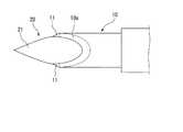
FIG. 1 is a diagram showing an overall configuration of a
図2Aは、針管10の先端部周辺を示す拡大図である。図2Bは、図2Aに示す矢印Aの方向から見た図である。針管10は、ステンレス等の金属で内腔を有する管状に形成されている。針管10は、外径が例えば1〜2ミリメートル(mm)程度と細く、可撓性を有している。図2Aおよび図2Bに示すように、針管10は、端部が鋭利な2か所の凸部11を先端側に有する。2つの凸部11は、針管10の先端側の端面が、針管10の軸線X1に対して傾斜し、且つ基端側に向かうにつれて針管10の外周面に近づく斜面10aおよび10bを有するように、針管10を形成する部材の一部を切除することにより形成されている。 FIG. 2A is an enlarged view showing the vicinity of the distal end portion of the
図3は、生検具1の先端部の断面図である。先端チップ20は、先端側に略円錐状の鋭利な穿刺部21を有する。先端チップ20の基端側は内腔を有する略円筒状に形成されている。先端チップ20の外径は針管10の内径よりも小さいため、図3に示すように、先端チップ20は針管10内に進入可能である。 FIG. 3 is a cross-sectional view of the distal end portion of the
先端チップ20の基端側には、針管10の先端部と同様の加工により、斜面20aおよび20b(斜面20bは不図示)が形成されている。傾斜面20a、20bの端部には、端部が鋭利な切刃部22を2か所有している。先端チップ20の内腔には、操作ワイヤ(操作部材)30が溶接等により接続されている。操作ワイヤ30は、針管10内を通って操作部50まで延びており、針管10に対して進退可能である。 On the proximal end side of the
先端チップ20と針管10とは、針管10の周方向において凸部11と切刃部22とが交互に位置するように位置決めされている。本実施形態では、2つの凸部11は、針管10の周方向において180度離れた位置に配置されている。2つの切刃部22は、先端チップ20の周方向において180度離れた位置に配置されている。そして、各切刃部22が、針管10の周方向において各凸部から90度離れた位置となるように先端チップ20と針管10との相対位置が規定されている。 The
シース40としては、可撓性を有し、針管10を進退可能に挿通できるものであればよく、公知のものを適宜選択して使用できる。材質についても特に制限はなく、例えば樹脂やコイル等の公知の各種材料を使用することができる。 The
操作部50は、図1に示すように、針管10の基端部に固定された操作部本体51と、操作部本体51の長手方向に摺動可能に取り付けられたスライダ52とを備えている。操作部50の基本構成は公知である。針管10内を通って延びた操作ワイヤ30の基端部は、操作部本体51の内部空間に突出し、スライダ52に固定されている。したがって、スライダ52を操作部本体51に対して摺動させることで、操作ワイヤ30を針管10に対して進退させることができる。操作部本体51をシース40に対して相対移動させると、針管10および先端チップ20をシース40に対して進退させることができる。これにより操作部50は、シース40の先端からの針管10および先端チップ20の突出量を調節することができる。 As shown in FIG. 1, the
上記のように構成された本実施形態に係る生検具1の使用時の動作について、膵臓を生検対象の組織(以下、単に「対象組織」と称する。)とする場合を例にとり説明する。 The operation when the
術者は、まず図示しない内視鏡を患者の体内に導入し、膵臓の付近まで内視鏡の先端部を移動させる。次に、針管10および先端チップ20がシース40内に収容された状態で、術者は、生検具1を穿刺部21側から内視鏡の鉗子チャンネルに挿入し、鉗子チャンネルの先端開口からシース40の先端部を突出させる。使用する内視鏡は、対象組織の種類や位置等に応じて、光学内視鏡や超音波内視鏡など、公知の各種のものを適宜選択してよい。 The surgeon first introduces an endoscope (not shown) into the patient's body and moves the distal end of the endoscope to the vicinity of the pancreas. Next, in a state where the
術者は、内視鏡の視野で膵臓および膵臓のうち組織片を採取する部位(採取部位)を確認しながら、操作部本体51を操作して、針管10および先端チップ20をシース40から突出させる。さらに、術者は、図4に示すように、穿刺部21を膵臓Pcに刺入し、穿刺部21を採取部位よりもわずか、例えば数ミリメートル程度手前の位置まで進める操作を行う。 The surgeon operates the operating portion
次に、術者がスライダ52を操作部本体51に対して前進させると、スライダ52に接続された操作ワイヤ30が針管10に対して前進し、図5に示すように、先端チップ20が針管10の前方に突出する。これにより、先端チップ20が針管10から離間し、先端チップ20と針管10との間に生じた空間に膵臓Pcの組織の一部が進入する。 Next, when the operator advances the slider 52 with respect to the operation portion
この状態で術者がスライダ52を操作部本体51に対して後退させると、図6に示すように、先端チップ20が後退して針管10に接近する。このとき、後退する先端チップ20の切刃部22が、先端チップ20と針管10との間に進入した組織を押圧しながら徐々に切る。進入した組織のうち、先端チップ20の周方向において2つの切刃部22の間に位置する部位は、先端チップ20では切りにくい。しかし、先端チップ20が針管10に接近すると、針管10の凸部11が当該部位を先端チップ20との間に挟むようにして押圧する。その結果、当該部位は先端チップ20と反対側から針管10の凸部11によって、徐々に切られる。先端チップ20の基端側に形成された斜面20aおよび図示しないもう一つの斜面が針管10の内腔内に位置するまで先端チップ20が後退されると、組織の一部が切り離され、組織片として針管10内に収容される。 When the operator retreats the slider 52 with respect to the operation portion
本実施形態に係る生検具1によれば、先端が鋭利な2か所の凸部11が針管10に設けられ、かつ先端チップ20にも先端が鋭利な2か所の切刃部22が設けられている。このため、先端チップ20を針管10に接近させて組織を徐々に切る際に、組織に作用する力を凸部11および切刃部22に集中させ、好適に組織を切ることができる。その結果、スライダ52を後退させるだけの容易な操作で確実に体組織を切離して採取することができる。 According to the
また、本実施形態に係る生検具1によれば、凸部11と切刃部22とが、針管10の周方向において交互に配置されている。このため、組織のうち凸部11で切りにくい部位は切刃部22で切られ、切刃部22で切りにくい部位は凸部11で切られる。その結果、さらに好適に体組織の切離および採取を行うことができる。 Further, according to the
上述した手技の流れにおいては、穿刺部を採取部位よりもわずかに手前の位置まで進めてから先端チップを針管に対して前進させる例を説明した。しかし、これに代えて、穿刺部を採取部位あるいは採取部位よりもわずかに奥側の位置まで進めた後、針管を先端チップに対して後退させる手技でもよい。このような操作でも、先端チップを針管に対して離間させることができる。この結果、その後、先端チップを針管に接近させることにより、同様に組織の切離および採取を行うことができる。 In the procedure flow described above, an example has been described in which the tip is advanced with respect to the needle tube after the puncture portion is advanced to a position slightly ahead of the collection site. However, instead of this, a technique may be used in which the puncture portion is advanced to the collection site or a position slightly behind the collection site, and then the needle tube is retracted relative to the tip. Even with such an operation, the tip can be separated from the needle tube. As a result, the tissue can be separated and collected in the same manner by moving the tip tip closer to the needle tube.
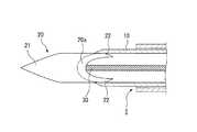
次に、本発明の第二実施形態について、図7を参照して説明する。本実施形態に係る生検具61と上述の生検針1との異なるところは、先端チップと針管との大小関係である。なお、以降の説明において、上述の実施形態と共通する構成については、同一の符号を付して重複する説明を省略する。 Next, a second embodiment of the present invention will be described with reference to FIG. The difference between the
図7は、生検具61における、針管63の先端部周辺の拡大図である。生検具61においては、図7に示すように、先端チップ62の基端側の内径が針管63の外径よりも大きく設定されており、凸部64を含む針管63の先端側が先端チップ62の基端側に進入可能に構成されている。その他の点については、概ね第一実施形態に係る生検具1と同様である。 FIG. 7 is an enlarged view around the distal end portion of the
本実施形態に係る生検具61においても、第一実施形態と同様に、スライダ52を後退させるだけの容易な操作で先端チップ62を針管63に接近させて、確実に体組織を切離して採取することができる。 Also in the
また、針管63が先端チップ62に突き当たると、それ以上先端チップ62が針管63に対して後退しなくなる。このため、穿刺部21を対象組織に対して刺入する際に組織からの反力が先端チップ62に作用しても、穿刺部21が針管63内に没入することがない。したがって、対象組織への刺入時に穿刺部21が針管63内に没入しないようにスライダ52を保持する必要がなく、より操作を簡易にすることができる。 Further, when the
以上、本発明の各実施形態を説明したが、本発明の技術範囲は上記実施形態に限定されるものではなく、本発明の趣旨を逸脱しない範囲において各実施形態における構成要素の組み合わせを変えたり、各構成要素に種々の変更を加えたり、削除したりすることが可能である。 The embodiments of the present invention have been described above. However, the technical scope of the present invention is not limited to the above embodiments, and combinations of components in the embodiments may be changed without departing from the spirit of the present invention. Various changes can be added to or deleted from each component.
例えば、本発明においては、凸部と切刃部の個数が同数であればよい。例えば、必ずしも上述の実施形態で説明したように凸部と切刃部とが2か所である必要はなく、凸部と切刃部とが3か所以上設けられてもよい。ただし、凸部および切刃部の個数が増えるほど、組織に作用する力が分散される。そのため、先端チップを針管に接近させる操作に必要な力量が大きくなる。したがって、凸部および切刃部の個数は2つとされるのが最も好ましい。
さらに、凸部および切刃部がそれぞれ1ヵ所である場合や、凸部と切刃部が同数でない場合でも一定の効果を得ることができる。For example, in the present invention, the number of convex portions and the number of cutting edge portions may be the same. For example, as described in the above-described embodiment, the convex portion and the cutting edge portion do not necessarily have to be two places, and the convex portion and the cutting edge portion may be provided in three or more places. However, as the number of convex portions and cutting blade portions increases, the force acting on the tissue is dispersed. Therefore, the amount of force required for the operation of bringing the tip end closer to the needle tube increases. Therefore, the number of convex portions and cutting blade portions is most preferably two.
Furthermore, a certain effect can be obtained even when the number of the convex portions and the cutting blade portions is one, or when the number of the convex portions and the cutting blade portions is not the same.
上記生検具によれば、容易な操作で確実に体組織を切離して採取することが可能な生検具を提供することができる。 According to the biopsy tool, it is possible to provide a biopsy tool capable of reliably separating and collecting body tissue with an easy operation.
1,61 生検具
10,63 針管
11,64 凸部
20,62 先端チップ
22 切刃部
30 操作ワイヤ(操作部材)1,61
Claims (5)
Translated fromJapanese前記針管に対して進退可能に設けられた先端チップと、
前記先端チップに接続されて前記針管に挿通される操作部材と、
前記先端チップの基端側に設けられ、端部が鋭利な切刃部と、
を備える生検具。A needle tube which is formed in a tubular shape and has a sharp convex part at the tip part;
A tip provided to be movable back and forth with respect to the needle tube;
An operating member connected to the tip and inserted through the needle tube;
A cutting edge portion provided on the base end side of the tip, and having a sharp end;
Biopsy tool with
前記針管は前記凸部を少なくとも2か所有し、
前記切刃部が前記凸部と同数設けられている。A biopsy instrument according to claim 1,
The needle tube has at least two of the convex portions,
The same number of the cutting blade portions as the convex portions are provided.
前記切刃部の端部は、前記針管の周方向において前記凸部の間に位置しており、前記凸部と前記切刃部とが、前記周方向において交互に配置されている。A biopsy instrument according to claim 1,
The edge part of the said cutting blade part is located between the said convex parts in the circumferential direction of the said needle tube, and the said convex part and the said cutting blade part are alternately arrange | positioned in the said circumferential direction.
前記先端チップは、先端側に鋭利な穿刺部を有する。A biopsy instrument according to claim 1,
The tip has a sharp puncture portion on the tip side.
前記針管の先端側は、前記先端チップ内に進入可能な寸法とされている。A biopsy instrument according to claim 1,
The distal end side of the needle tube is dimensioned to enter the distal tip.
Applications Claiming Priority (3)
| Application Number | Priority Date | Filing Date | Title |
|---|---|---|---|
| US201261710210P | 2012-10-05 | 2012-10-05 | |
| US61/710,210 | 2012-10-05 | ||
| PCT/JP2013/076243WO2014054525A1 (en) | 2012-10-05 | 2013-09-27 | Biopsy instrument |
Publications (2)
| Publication Number | Publication Date |
|---|---|
| JP5577000B1true JP5577000B1 (en) | 2014-08-20 |
| JPWO2014054525A1 JPWO2014054525A1 (en) | 2016-08-25 |
Family
ID=50434853
Family Applications (1)
| Application Number | Title | Priority Date | Filing Date |
|---|---|---|---|
| JP2014512984AActiveJP5577000B1 (en) | 2012-10-05 | 2013-09-27 | Biopsy tool |
Country Status (5)
| Country | Link |
|---|---|
| US (1) | US20150094614A1 (en) |
| EP (1) | EP2904976B1 (en) |
| JP (1) | JP5577000B1 (en) |
| CN (1) | CN104271049B (en) |
| WO (1) | WO2014054525A1 (en) |
Families Citing this family (1)
| Publication number | Priority date | Publication date | Assignee | Title |
|---|---|---|---|---|
| CN106068101B (en)* | 2015-02-19 | 2019-05-28 | 奥林巴斯株式会社 | Biopsy needle |
Citations (9)
| Publication number | Priority date | Publication date | Assignee | Title |
|---|---|---|---|---|
| US1867624A (en)* | 1930-04-01 | 1932-07-19 | Memorial Hospital For The Trea | Device for obtaining biopsy specimens |
| US3705577A (en)* | 1969-10-02 | 1972-12-12 | Rafael B Sierra | Biopsy needle with eccentrically-mounted cutting tip |
| JPS4874687U (en)* | 1971-12-21 | 1973-09-17 | ||
| JPS4888691U (en)* | 1972-01-26 | 1973-10-25 | ||
| JPS61279236A (en)* | 1985-06-03 | 1986-12-10 | オリンパス光学工業株式会社 | Sampler for living body tissue |
| JPH11262490A (en)* | 1997-11-24 | 1999-09-28 | Ethicon Endo Surgery Inc | Biopsy assembly |
| JP2001170059A (en)* | 1999-12-22 | 2001-06-26 | Asahi Optical Co Ltd | Endoscope tissue collection tool |
| JP2003533325A (en)* | 2000-05-24 | 2003-11-11 | デジンガー カイ | Surgical hollow sonde |
| JP2012527986A (en)* | 2009-05-28 | 2012-11-12 | アンジオテック ファーマシューチカルズ インコーポレイテッド | Biopsy device needle set |
Family Cites Families (7)
| Publication number | Priority date | Publication date | Assignee | Title |
|---|---|---|---|---|
| NZ272451A (en)* | 1994-06-28 | 1997-11-24 | Meat Research Corp | Animal tissue testing; portion of tissue removed from carcass tested by measurement of ph of sample after incubation |
| US5980468A (en)* | 1997-09-22 | 1999-11-09 | Zimmon Scientific Corporation | Apparatus and method for serial collection storage and processing of biopsy specimens |
| US6030400A (en)* | 1998-10-16 | 2000-02-29 | Johnson; Lanny L. | Articular cartilage harvesting knife |
| DK176336B1 (en)* | 1999-12-22 | 2007-08-20 | Asahi Optical Co Ltd | Endoscopic tissue collection instrument |
| DE10342002A1 (en)* | 2003-09-05 | 2005-04-14 | Karl Storz Gmbh & Co. Kg | Medical instrument for the preparation of tissue |
| DE102007046397A1 (en)* | 2007-09-21 | 2009-04-02 | Karl Storz Gmbh & Co. Kg | Medical instrument for punching out tissue |
| US8617086B2 (en)* | 2010-07-01 | 2013-12-31 | Uti Limited Partnership | Methods and apparatuses for full-thickness hollow organ biopsy |
- 2013
- 2013-09-27WOPCT/JP2013/076243patent/WO2014054525A1/enactiveApplication Filing
- 2013-09-27JPJP2014512984Apatent/JP5577000B1/enactiveActive
- 2013-09-27EPEP13843120.0Apatent/EP2904976B1/enactiveActive
- 2013-09-27CNCN201380023330.6Apatent/CN104271049B/enactiveActive
- 2014
- 2014-07-30USUS14/446,827patent/US20150094614A1/ennot_activeAbandoned
Patent Citations (9)
| Publication number | Priority date | Publication date | Assignee | Title |
|---|---|---|---|---|
| US1867624A (en)* | 1930-04-01 | 1932-07-19 | Memorial Hospital For The Trea | Device for obtaining biopsy specimens |
| US3705577A (en)* | 1969-10-02 | 1972-12-12 | Rafael B Sierra | Biopsy needle with eccentrically-mounted cutting tip |
| JPS4874687U (en)* | 1971-12-21 | 1973-09-17 | ||
| JPS4888691U (en)* | 1972-01-26 | 1973-10-25 | ||
| JPS61279236A (en)* | 1985-06-03 | 1986-12-10 | オリンパス光学工業株式会社 | Sampler for living body tissue |
| JPH11262490A (en)* | 1997-11-24 | 1999-09-28 | Ethicon Endo Surgery Inc | Biopsy assembly |
| JP2001170059A (en)* | 1999-12-22 | 2001-06-26 | Asahi Optical Co Ltd | Endoscope tissue collection tool |
| JP2003533325A (en)* | 2000-05-24 | 2003-11-11 | デジンガー カイ | Surgical hollow sonde |
| JP2012527986A (en)* | 2009-05-28 | 2012-11-12 | アンジオテック ファーマシューチカルズ インコーポレイテッド | Biopsy device needle set |
Also Published As
| Publication number | Publication date |
|---|---|
| JPWO2014054525A1 (en) | 2016-08-25 |
| EP2904976A4 (en) | 2016-06-08 |
| WO2014054525A1 (en) | 2014-04-10 |
| CN104271049A (en) | 2015-01-07 |
| EP2904976A1 (en) | 2015-08-12 |
| US20150094614A1 (en) | 2015-04-02 |
| EP2904976B1 (en) | 2019-04-24 |
| CN104271049B (en) | 2016-10-12 |
Similar Documents
| Publication | Publication Date | Title |
|---|---|---|
| JP5591416B2 (en) | Endoscopic treatment tool | |
| EP2598037B1 (en) | Coaxial incisional full-core biopsy needle | |
| JP5908195B1 (en) | Puncture treatment tool | |
| WO2014112518A1 (en) | Tissue sampling device | |
| JP7419067B2 (en) | biopsy device | |
| US20040133124A1 (en) | Flexible biopsy needle | |
| JP6097826B2 (en) | Tissue collection device | |
| US20080281224A1 (en) | Biopsy device needle tip | |
| AU2005245226A1 (en) | Method of manufacturing a needle assembly for use with a biopsy device | |
| US20180098758A1 (en) | Biopsy needle | |
| US20160081675A1 (en) | Helical driven rotating tissue collection | |
| JP5577000B1 (en) | Biopsy tool | |
| US11229423B2 (en) | Tissue collecting instrument | |
| WO2014061505A1 (en) | Treatment tool for endoscope | |
| US20230404551A1 (en) | Deployable Tubular Biopsy Device | |
| JP4879763B2 (en) | Biopsy needle | |
| CN105979881B (en) | Medical treatment instrument | |
| JP7263055B2 (en) | biopsy needle | |
| JPH11342133A (en) | Treatment device for endoscope | |
| JP2005137815A (en) | Puncturing needle | |
| WO2019202764A1 (en) | Treatment tool | |
| JP2015019872A (en) | Incision tool |
Legal Events
| Date | Code | Title | Description |
|---|---|---|---|
| A521 | Request for written amendment filed | Free format text:JAPANESE INTERMEDIATE CODE: A523 Effective date:20140521 | |
| A521 | Request for written amendment filed | Free format text:JAPANESE INTERMEDIATE CODE: A821 Effective date:20140522 | |
| TRDD | Decision of grant or rejection written | ||
| A01 | Written decision to grant a patent or to grant a registration (utility model) | Free format text:JAPANESE INTERMEDIATE CODE: A01 Effective date:20140617 | |
| A61 | First payment of annual fees (during grant procedure) | Free format text:JAPANESE INTERMEDIATE CODE: A61 Effective date:20140704 | |
| R151 | Written notification of patent or utility model registration | Ref document number:5577000 Country of ref document:JP Free format text:JAPANESE INTERMEDIATE CODE: R151 | |
| S111 | Request for change of ownership or part of ownership | Free format text:JAPANESE INTERMEDIATE CODE: R313111 | |
| R350 | Written notification of registration of transfer | Free format text:JAPANESE INTERMEDIATE CODE: R350 | |
| S531 | Written request for registration of change of domicile | Free format text:JAPANESE INTERMEDIATE CODE: R313531 | |
| R350 | Written notification of registration of transfer | Free format text:JAPANESE INTERMEDIATE CODE: R350 | |
| R250 | Receipt of annual fees | Free format text:JAPANESE INTERMEDIATE CODE: R250 | |
| R250 | Receipt of annual fees | Free format text:JAPANESE INTERMEDIATE CODE: R250 | |
| R250 | Receipt of annual fees | Free format text:JAPANESE INTERMEDIATE CODE: R250 | |
| R250 | Receipt of annual fees | Free format text:JAPANESE INTERMEDIATE CODE: R250 | |
| R250 | Receipt of annual fees | Free format text:JAPANESE INTERMEDIATE CODE: R250 | |
| R250 | Receipt of annual fees | Free format text:JAPANESE INTERMEDIATE CODE: R250 | |
| R250 | Receipt of annual fees | Free format text:JAPANESE INTERMEDIATE CODE: R250 |