JP5576821B2 - Electronics - Google Patents
ElectronicsDownload PDFInfo
- Publication number
- JP5576821B2 JP5576821B2JP2011065463AJP2011065463AJP5576821B2JP 5576821 B2JP5576821 B2JP 5576821B2JP 2011065463 AJP2011065463 AJP 2011065463AJP 2011065463 AJP2011065463 AJP 2011065463AJP 5576821 B2JP5576821 B2JP 5576821B2
- Authority
- JP
- Japan
- Prior art keywords
- unit
- housing
- diaphragm
- speaker
- disposed
- Prior art date
- Legal status (The legal status is an assumption and is not a legal conclusion. Google has not performed a legal analysis and makes no representation as to the accuracy of the status listed.)
- Expired - Fee Related
Links
Images


Classifications
- H—ELECTRICITY
- H04—ELECTRIC COMMUNICATION TECHNIQUE
- H04M—TELEPHONIC COMMUNICATION
- H04M1/00—Substation equipment, e.g. for use by subscribers
- H04M1/02—Constructional features of telephone sets
- H04M1/03—Constructional features of telephone transmitters or receivers, e.g. telephone hand-sets
- H—ELECTRICITY
- H04—ELECTRIC COMMUNICATION TECHNIQUE
- H04M—TELEPHONIC COMMUNICATION
- H04M1/00—Substation equipment, e.g. for use by subscribers
- H04M1/02—Constructional features of telephone sets
- H04M1/0202—Portable telephone sets, e.g. cordless phones, mobile phones or bar type handsets
- H04M1/026—Details of the structure or mounting of specific components
- H—ELECTRICITY
- H04—ELECTRIC COMMUNICATION TECHNIQUE
- H04R—LOUDSPEAKERS, MICROPHONES, GRAMOPHONE PICK-UPS OR LIKE ACOUSTIC ELECTROMECHANICAL TRANSDUCERS; DEAF-AID SETS; PUBLIC ADDRESS SYSTEMS
- H04R17/00—Piezoelectric transducers; Electrostrictive transducers
- B—PERFORMING OPERATIONS; TRANSPORTING
- B29—WORKING OF PLASTICS; WORKING OF SUBSTANCES IN A PLASTIC STATE IN GENERAL
- B29C—SHAPING OR JOINING OF PLASTICS; SHAPING OF MATERIAL IN A PLASTIC STATE, NOT OTHERWISE PROVIDED FOR; AFTER-TREATMENT OF THE SHAPED PRODUCTS, e.g. REPAIRING
- B29C45/00—Injection moulding, i.e. forcing the required volume of moulding material through a nozzle into a closed mould; Apparatus therefor
- B29C45/14—Injection moulding, i.e. forcing the required volume of moulding material through a nozzle into a closed mould; Apparatus therefor incorporating preformed parts or layers, e.g. injection moulding around inserts or for coating articles
- B—PERFORMING OPERATIONS; TRANSPORTING
- B29—WORKING OF PLASTICS; WORKING OF SUBSTANCES IN A PLASTIC STATE IN GENERAL
- B29L—INDEXING SCHEME ASSOCIATED WITH SUBCLASS B29C, RELATING TO PARTICULAR ARTICLES
- B29L2031/00—Other particular articles
- B29L2031/34—Electrical apparatus, e.g. sparking plugs or parts thereof
- B29L2031/3418—Loud speakers
- B—PERFORMING OPERATIONS; TRANSPORTING
- B29—WORKING OF PLASTICS; WORKING OF SUBSTANCES IN A PLASTIC STATE IN GENERAL
- B29L—INDEXING SCHEME ASSOCIATED WITH SUBCLASS B29C, RELATING TO PARTICULAR ARTICLES
- B29L2031/00—Other particular articles
- B29L2031/34—Electrical apparatus, e.g. sparking plugs or parts thereof
- B29L2031/3431—Telephones, Earphones
- B29L2031/3437—Cellular phones
- H—ELECTRICITY
- H04—ELECTRIC COMMUNICATION TECHNIQUE
- H04R—LOUDSPEAKERS, MICROPHONES, GRAMOPHONE PICK-UPS OR LIKE ACOUSTIC ELECTROMECHANICAL TRANSDUCERS; DEAF-AID SETS; PUBLIC ADDRESS SYSTEMS
- H04R2400/00—Loudspeakers
- H04R2400/11—Aspects regarding the frame of loudspeaker transducers
Landscapes
- Engineering & Computer Science (AREA)
- Signal Processing (AREA)
- Physics & Mathematics (AREA)
- Acoustics & Sound (AREA)
- Telephone Set Structure (AREA)
- Details Of Audible-Bandwidth Transducers (AREA)
Description
Translated fromJapanese本発明は、携帯電話機等の電子機器に関する。 The present invention relates to an electronic device such as a mobile phone.
従来、携帯電話機等の電子機器において、スピーカを有するものがある。
そして、近年、電子機器に対してコンパクト化が求められており、スピーカを有する電子機器に対しても小型化や薄型化が求められている。
これに対し、電子機器のコンパクト化に寄与できる薄型のスピーカとして、圧電素子を用いたスピーカが提案されている。(例えば、特許文献1参照)。Conventionally, some electronic devices such as mobile phones have a speaker.
In recent years, electronic devices have been required to be compact, and electronic devices having speakers have also been required to be small and thin.
On the other hand, a speaker using a piezoelectric element has been proposed as a thin speaker that can contribute to a compact electronic device. (For example, refer to Patent Document 1).
しかし、特許文献1の電子機器において、圧電素子が取りけられた振動板を保持するフレームは、振動板からの強い反発力に耐えられるようカバー部材等に強固に固定される必要があった。
この場合、当該電子機器において、スピーカをカバー部材等に強固に固定するための両面テープや固定ビス等が必要であった。
また、スピーカのフレームは、振動板をしっかりと保持するため、一定程度の大きさが必要であった。このことは、電子機器のコンパクト化を規制する一因になっていた。However, in the electronic device of
In this case, in the electronic device, a double-sided tape, a fixing screw or the like for firmly fixing the speaker to the cover member or the like is necessary.
Further, the speaker frame needs to have a certain size in order to hold the diaphragm firmly. This has been a factor in restricting the downsizing of electronic devices.
本発明は、カバー部材と一体的に成型されたスピーカを有する電子機器を提供することを目的とする。 An object of this invention is to provide the electronic device which has a speaker integrally molded with the cover member.
本発明は、少なくとも一部が樹脂製のケース部材と、前記ケース部材と一体的に成型されるスピーカ部であって、振動発生部と、前記振動発生部から伝達された振動により振動する振動板と、前記振動板における外縁を保持すると共に、全部又は一部が前記ケース部材にインサート成型された保持部と、を有するスピーカ部と、を備える電子機器に関する。 The present invention relates to a case member made of at least a part of resin, a speaker unit molded integrally with the case member, and a vibration generating unit and a vibration plate that vibrates due to vibration transmitted from the vibration generating unit And a speaker unit that holds an outer edge of the diaphragm and a holding unit that is insert-molded in whole or in part in the case member.
また、電子機器において、前記振動板は、防水性を有することが好ましい。 In the electronic device, the diaphragm is preferably waterproof.
また、電子機器は、前記ケース部材に収容配置され給電部を有する基板と、を備え、前記保持部は、導電性部材により構成され、前記給電部に電気的に接続される被当接部を有することが好ましい。 In addition, the electronic apparatus includes a substrate housed in the case member and having a power feeding unit, and the holding unit includes a conductive member and includes a contacted part electrically connected to the power feeding unit. It is preferable to have.
また、電子機器において、前記保持部は、所定形状に形成され、アンテナとして機能することが好ましい。 In the electronic device, it is preferable that the holding portion is formed in a predetermined shape and functions as an antenna.
また、電子機器において、前記振動部は、圧電素子を有して構成されると共に、前記振動板における一方の面に積層配置されることが好ましい。 In the electronic device, it is preferable that the vibration unit includes a piezoelectric element and is laminated on one surface of the vibration plate.
また、電子機器は、前記ケース部材を有して構成されると共に、前記スピーカが配置される第1面と、前記第1面と反対側の第2面とを有する第1筐体と、第3面と、前記第3面と反対側の第4面とを有する第2筐体と、前記第1筐体と前記第2筐体とを回動可能に連結する連結部であって、前記第1筐体における長手方向の一端側と前記第2筐体における長手方向の一端側とを連結すると共に、前記第2面と前記第3面とが近接配置される閉状態と、前記第2面と前記3面とが離間して配置される開状態とに変更可能に前記第1筐体と前記第2筐体とを連結する連結部と、を備え、前記第1筐体における第2面側には、磁気センサーが配置され、前記第2筐体における第3面側には、磁石が前記閉状態において前記磁気センサーに近接配置される位置に配置されると共に、スピーカが前記長手方向における他端側に配置されることが好ましい。 The electronic device includes the case member, a first housing having a first surface on which the speaker is disposed, and a second surface opposite to the first surface; A second housing having three surfaces and a fourth surface opposite to the third surface, and a connecting portion for rotatably connecting the first housing and the second housing, A closed state in which one end side in the longitudinal direction of the first housing and one end side in the longitudinal direction of the second housing are connected, and the second surface and the third surface are arranged close to each other; A connecting portion that connects the first housing and the second housing so that the first housing and the second housing can be changed to an open state in which a surface and the three surfaces are spaced apart from each other. A magnetic sensor is disposed on the surface side, and a magnet is disposed close to the magnetic sensor in the closed state on the third surface side of the second housing. Together it is arranged at a position that is, a speaker is preferably disposed on the other end side in the longitudinal direction.
また、電子機器において、前記保持部は、当該保持部における前記振動板の垂線方向からみた面積が、前記振動板における該保持部に囲まれた部分の前記垂線方向からみた面積よりも大きいことが好ましい。 In the electronic device, the holding unit may have an area of the holding unit as viewed from a direction perpendicular to the diaphragm, which is larger than an area of the diaphragm surrounded by the holding unit from the direction of the perpendicular. preferable.
本発明によれば、カバー部材と一体的に成型されたスピーカを有する電子機器を提供することができる。 ADVANTAGE OF THE INVENTION According to this invention, the electronic device which has a speaker integrally molded with the cover member can be provided.
以下、本発明の電子機器としての携帯電話機について説明する。
まず、図1から図5Cにより、第1実施形態における携帯電話機1について説明する。
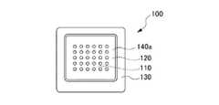
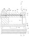
図1は、第1実施形態における携帯電話機1の正面図である。図2は、第1実施形態における携帯電話機1の裏面図である。図3は、図2におけるA−A断面図である。図4は、図3における領域Bの拡大図である。図5Aは、第1実施形態におけるスピーカ部100の正面図である。図5Bは、第1実施形態におけるスピーカ部100の側面図である。図5Cは、第1実施形態におけるスピーカ部100の裏面図である。Hereinafter, a mobile phone as an electronic apparatus of the present invention will be described.
First, the
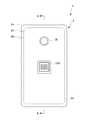
FIG. 1 is a front view of a
図1から図3に示すように、携帯電話機1は、筐体2を備える。
筐体2は、保護パネル10と、LCDパネル部11と、タッチパネル12と、シールドケース14と、回路基板15と、カメラ部16と、バッテリ17と、スピーカ部100と、ケース部材20とを備える。As shown in FIGS. 1 to 3, the
The
筐体2における外郭は、表面2a側に配置される保護パネル10と、ケース部材20とにより構成される。また、保護パネル10とケース部材20とにより筐体2の内部空間が形成される。
筐体2(内部空間)には、表面2a側から順に、LCDパネル部11と、タッチパネル12と、シールドケース14と、回路基板15と、カメラ部16及びバッテリ17とが収容配置される。ここで、スピーカ部100は、ケース部材20と一体的に成型される。スピーカ部100は、後述するフレーム130がケース部材20を構成する平壁部21に埋め込まれるようにして配置される。The outer shell of the
In the housing 2 (internal space), an
保護パネル10は、LCDパネル部11及びタッチパネル12の外表面側(表面2a側)に配置される。
保護パネル10は、ユーザの指等が接触される部分である。
また、保護パネル10は、上述の通り、ケース部材20とともに筐体2の外郭を形成する部材である。The
The
Further, as described above, the
LCDパネル部11は、表示面11aを有する。
LCDパネル部11は、表示面11aが外部から視認可能に筐体2に収容配置される。
LCDパネル部11は、本実施形態において、液晶を用いた表示デバイスである。LCDパネル部11は、駆動回路と、背面側から光を照射するバックライト等の光源部とを有して構成される。
LCDパネル部11は、フレキシブルプリント基板等を介して、回路基板15と電気的に接続される。
ここで、表示部材としては、有機EL(エレクトロルミネッセンス)や電子インクを用いた表示デバイスが使用されてもよい。The
The
The
The
Here, as the display member, a display device using organic EL (electroluminescence) or electronic ink may be used.
タッチパネル12は、外部からの入力を受け付ける。タッチパネル12は、ユーザからの操作を受け付ける操作部受付部として機能する。
具体的には、タッチパネル12は、保護パネル10に対するユーザの指やタッチペン等の接触を検出する。タッチパネル12として、例えば、静電容量方式、抵抗膜方式や電磁誘導方式等のセンサーが用いられる。The
Specifically, the
シールドケース14は、薄型の直方体における一の広い面が開口した形状を有する導電性の部材である。シールドケース14は、LCDパネル部11に積層配置される平板部と、平板部の外縁から回路基板15側に延出するリブとを有する。
シールドケース14は、後述する回路基板15に実装された電子部品15bを覆うように配置される。
また、シールドケース14は、リブの端面が後述する回路基板15の基準電位パターン15a上に載置されるように配置される。The
The
The
回路基板15は、シールドケース14側に形成される基準電位パターン15aと、シールドケース14側に実装される複数の電子部品15bとを有する。
上述の通り、基準電位パターン15aには、シールドケース14におけるリブの端面が当接される。複数の電子部品15bは、シールドケース14に覆われる。
また、回路基板15は、フレキシブルプリント基板等を介してLCDパネル部11と電気的に接続される。The
As described above, the end surface of the rib in the
The
カメラ部16は、回路基板15におけるシールドケース14と反対側に配置される。
カメラ部16は、レンズ16a側がカメラ用孔26を介して筐体2の外部に露出して配置される。
カメラ部16は、不図示のフレキシブルプリント基板を介して回路基板15に電気的に接続される。The
The
The
バッテリ17は、回路基板15におけるシールドケース14と反対側に配置される。
バッテリ17は、不図示のバッテリカバーを取り外すことで露出されるバッテリ開口を介して、筐体2の内部に挿入される。
バッテリ17は、バッテリ開口を介して筐体2に装脱可能に配置される。The
The
The
ケース部材20は、表面2a側が開口した箱状の部材である。ケース部材20は、上述の通り、保護パネル10とともに筐体2の外郭を構成する。
ケース部材20は、少なくとも一部が樹脂製のケース部材である。
ケース部材20は、平壁部21と、平壁部21の外縁から保護パネル10側に延びる側壁部22とを有する。The
The
The
平壁部21は、樹脂部23と、厚さ方向における内部に配置される板金部24とを有する。平壁部21は、板金部24をインサート成型して形成される。平壁部21は、板金部24が内部に埋め込まれているので、剛性が向上されている。 The
平壁部21は、カメラ部16を露出させるカメラ用孔26と、スピーカ部100を露出させるスピーカ用孔27とを有する。
カメラ用孔26は、上述の通り、筐体2の内部に配置されたカメラ部16のレンズ16a側を外部に露出させる。The
As described above, the
スピーカ用孔27は、後述するスピーカ部100における振動板120に対応する部分を外部に露出させる。
スピーカ用孔27における外縁から所定幅の部分には、後述するスピーカ部100のフレーム130の外縁が樹脂部23に埋め込まれた状態で配置される。The
An outer edge of a
スピーカ部100は、ケース部材20と一体的に成型される。スピーカ部100は、後述するフレーム130がケース部材20を構成する平壁部21(樹脂部23)に埋め込まれるようにして配置される。 The
スピーカ部100は、圧電素子部110(振動発生部)と、振動板120と、フレーム130(保持部)と、保護カバー140(140a、14b)と、給電部150とを有する。 The
圧電素子部110(振動発生部)は、薄いシート状の部材である。
圧電素子部110は、後述する振動板120における一方の面側(本実施形態においては外面側)に積層配置される。圧電素子部110は、振動板120における中央部に貼り付けられて配置される。
圧電素子部110は、例えば、圧電素子を金属板に貼り合わせた構造や、圧電素子を2枚の電極で挟む構成を有する。
圧電素子部110は、後述する給電部150を介して供給される電圧により振動を発生させる。
圧電素子部110は、振動板120に貼り合わされているので、発生させた振動を振動板120に伝達させる。The piezoelectric element portion 110 (vibration generating portion) is a thin sheet-like member.
The
The
The
Since the
振動板120は、正方形状の薄い板状部材である。振動板120は、外縁を後述するフレーム130に保持される。
振動板120は、圧電素子部110から伝達された振動により振動する。振動板120は、中央部(圧電素子部110が配置された領域)が上下するようにして振動する。振動板120が振動することで、音声が発生する。
振動板120は、防水性を有していることが好ましい。振動板120は、例えば、防水性を有する材料(例えば、ポリイミド、ポリエチレン、ポロカーボネート等)で構成されていてもよい。The
The
The
フレーム130(保持部)は、振動板120における外縁を保持する。フレーム130は、振動板120の外縁を囲むように配置される。フレーム130は、本実施形態において、四角のリング状に形成される。フレーム130は、振動板120の外縁を厚さ方向に挟むようにして保持する。本実施形態において、フレーム130は、金属製である。 The frame 130 (holding unit) holds the outer edge of the
フレーム130は、全部又は一部がケース部材20にインサート成型される。
フレーム130は、平壁部21に一部が埋め込まれた状態でケース部材20に取り付けられる。
フレーム130は、ケース部材20に埋め込まれて取り付けられるので、振動板120から受ける力により移動しない状態で固定される。
また、フレーム130は、スピーカ用孔27を形成するために板金部24に形成された孔部の内縁と、該フレーム130の外縁が近接するように配置されることで、ケース部材20(平壁部21)における剛性を向上させる。All or part of the
The
Since the
Further, the
保護カバー140(140a、14b)は、スピーカ部100の両面に貼り付けられて配置される。保護カバー140aは、スピーカ部100における表面側(外面側)に配置される。保護カバー140aは、圧電素子部110及び振動板120における一方の面を覆うように配置される。また、保護カバー140aは、複数の孔を有して構成される。 The protective covers 140 (140a, 14b) are disposed on both surfaces of the
保護カバー140bは、スピーカ部100における裏面側(内面側)に配置される。保護カバー140bは、振動板120における他方の面を覆うように配置される。ここで、保護カバー140bは、複数の孔を有しない。 The
給電部150は、スピーカ部100における裏面側(内面側)に配置(形成)される。給電部150は、フレーム130の一部を切り欠いた領域に配置される。
給電部150は、不図示のフレキシブルプリント基板等を介して回路基板15から電圧の供給を受ける。給電部150は、回路基板15から受けた電圧を圧電素子部110に供給する。The
The
ここで、スピーカ部100は、圧電素子を用いるタイプであるので、磁石等を必要としない。本実施形態の圧電素子を用いたスピーカ部100は、薄型タイプであると共に、他の電子部品等に対して磁力による影響を与えない。 Here, since the
本実施形態によれば、携帯電話機1は、スピーカ部100のフレーム130が平壁部21に埋め込まれているので、薄型化可能である。 According to the present embodiment, the
また、本実施形態によれば、携帯電話機1は、スピーカ部100のフレーム130が平壁部21に埋め込まれているので、フレーム130の分だけ長手方向又は短手方向において小型化可能である。 Further, according to the present embodiment, since the
また、本実施形態によれば、携帯電話機1は、スピーカ部100のフレーム130が平壁部21に埋め込まれているので、スピーカ部100を隙間無く強固に固定できる。 Further, according to the present embodiment, since the
また、本実施形態によれば、携帯電話機1は、スピーカ部100のフレーム130が平壁部21に埋め込まれているので、スピーカ部100をケース部材20に固定するための部材(両面テープやネジ)等を用いることなく、スピーカ部100をケース部材20に取り付けられる。
これにより、携帯電話機1は、必要な部材(部品)の数を減らすことができる。また、これにより、携帯電話機1は、製造コストを減らすことができる。
また、これにより、携帯電話機1は、スピーカ部100をケース部材20に固定するための部材(両面テープやネジ)の不具合、取り付け位置のずれ、取り付け時の押圧不足等による生じる悪影響を抑制できる。In addition, according to the present embodiment, since the
Thereby, the
Accordingly, the
また、本実施形態によれば、携帯電話機1は、スピーカ部100のフレーム130が平壁部21に埋め込まれているので、スピーカ部100をケース部材20に固定するための平面領域等を形成する必要がなく、製造負担を減少させることができる。 Further, according to the present embodiment, since the
また、本実施形態によれば、携帯電話機1は、スピーカ部100のフレーム130が平壁部21に埋め込まれているので、スピーカ部100における配置が制限されない。例えば、スピーカ部100は、厚さ方向においてバッテリと重なる位置に配置されていてもよい。つまり、携帯電話機1における設計の自由度が向上される。 Moreover, according to this embodiment, since the
また、本実施形態によれば、携帯電話機1は、金型を用いたインサート成型によりスピーカ部100のフレーム130が平壁部21に埋め込まれているので、スピーカ部100における位置精度を高くできる。 Further, according to the present embodiment, since the
また、本実施形態によれば、携帯電話機1は、スピーカ部100のフレーム130が平壁部21に埋め込まれているので、スピーカ部100を固定した後に生じる経年劣化や熱による悪影響(例えば、接着テープが劣化等)が生じることを抑制できる。 In addition, according to the present embodiment, since the
また、本実施形態によれば、携帯電話機1は、スピーカ部100のフレーム130が平壁部21に埋め込まれているので、フレーム130をしっかりと保持する。これにより、携帯電話機1は、振動板120からの反力でフレーム130が移動することを抑制して、音響性を向上させる。 In addition, according to the present embodiment, the
また、本実施形態によれば、携帯電話機1は、スピーカ部100のフレーム130が平壁部21に埋め込まれているので、振動板120等を大型化してもフレーム130を大型化(厚さが厚くなる等)させる必要がない。これにより、携帯電話機1は、大型化されることなく、スピーカの性能を向上させることができる。 In addition, according to the present embodiment, since the
また、本実施形態によれば、携帯電話機1は、スピーカ部100のフレーム130が平壁部21に埋め込まれているので、防水性が向上される。また、携帯電話機1は、スピーカ部100に対しては防水シール部材等が不要であるため、防水性向上のためのコストを減らすことができる。
更に、振動板120が防水性を有する材料で構成される場合、携帯電話機1は、防水性が更に向上される。Moreover, according to this embodiment, since the
Further, when the
また、本実施形態によれば、スピーカ部100は、振動発生部として圧電素子を含む圧電素子部が用いられている。
これにより、携帯電話機1は、磁石を必要としない薄型のスピーカ部100を有する。
これにより、携帯電話機1は、薄型化可能であると共に、磁力の影響による部品配置の制限が少ない構成にできる。According to the present embodiment, the
Accordingly, the
As a result, the
また、本実施形態によれば、ケース部材20において、剛性向上のためインサート成型された板金部24に形成された孔(スピーカ用孔27に対応する部分)の内縁近傍に、スピーカ部100におけるフレーム130の外縁が並んで配置される(フレーム130がインサート成型)。これにより、携帯電話機1は、剛性が向上される。 Further, according to the present embodiment, in the
また、本実施形態によれば、携帯電話機1は、フレーム130を回路基板15に形成されたグランドに電気的に接続されるよう構成することで、静電気が帯電した場合に生じる悪影響を抑制できる。 In addition, according to the present embodiment, the
また、本実施形態によれば、携帯電話機1は、スピーカ部100のフレーム130が平壁部21に埋め込まれているので、取り付けられるスピーカ部100の形状を制限しない。 Further, according to the present embodiment, the
また、本実施形態によれば、携帯電話機1は、スピーカ部100のフレーム130が平壁部21に埋め込まれているので、取り付けられるスピーカ部100のフレーム130における大きさや形状を制限しない。 Moreover, according to this embodiment, since the
続けて、図6及び図7により、第2実施形態における携帯電話機1Aについて説明する。
図6は、第2実施形態における携帯電話機1Aの部分拡大断面図である。図7は、第2実施形態におけるスピーカ部100Aの裏面図である。
以下、上述した携帯電話機1と同様の構成については説明を省略し、異なる構成を中心に説明をする。Next, a
FIG. 6 is a partially enlarged cross-sectional view of the
Hereinafter, the description of the same configuration as that of the
図6及び図7に示すように、本実施形態におけるスピーカ部100Aは、第1実施形態におけるスピーカ部100と比べて、フレーム130の形状が異なる。本実施形態において、フレーム130Aは導電部材(例えば、金属)により構成される。
また、本実施形態におけるスピーカ部100Aは、延出部133及びアンテナ側被給電部135を有する点で第1実施形態におけるスピーカ部100と異なる。
また、本実施形態における回路基板15Aは、アンテナ側被給電部135に当接されると共に、アンテナ側被給電部135を介して後述するアンテナ部132に給電可能なアンテナ用給電部15cを有する点で第1実施形態における回路基板15Aと異なる。As shown in FIGS. 6 and 7, the
The
In addition, the
具体的には、スピーカ部100Aにおけるフレーム130Aは、振動板120の外縁(外周)に配置される外周部131と、外周部131から延出部して形成されるアンテナ部132とを有する。
外周部131は、振動板120を保持する部分である。
アンテナ部132は、外周部131の外縁に沿って直線状に所定幅で延出する部分である。Specifically, the
The outer
The
また、スピーカ部100Aにおけるフレーム130Aは、外周部131における回路基板15側の面から延出する延出部133を有する。
延出部133は、回路基板15側と反対側の端部に形成されるアンテナ側被給電部135を有する。Further, the
The extending
アンテナ側被給電部135は、回路基板15Aにおけるスピーカ部100A側に形成されたアンテナ用給電部15cに電気的に接続(本実施形態においては当接)される。
アンテナ用給電部15cは、アンテナ側被給電部135を介して後述するアンテナ部132に給電可能に構成される。The antenna-side power-supplied
The antenna
上述の構成により、フレーム130Aにおけるアンテナ部132は、アンテナとして機能する。アンテナ部132(フレーム130A)の形状や延出長は、対応する周波数(波長)に応じて設定される。
また、アンテナ部132は、アンテナ用給電部15c及びアンテナ側被給電部135を介して、回路基板15Aに実装される不図示のRFモジュール等に接続される。With the above-described configuration, the
The
本実施形態によれば、携帯電話機1Aは、フレーム130Aの一部をアンテナとして利用することができる。これにより、携帯電話機1Aは、スピーカ部100Aにおけるフレーム130Aを有効に活用できる。
また、本実施形態によれば、携帯電話機1Aは、アンテナ部132が平壁部21に埋め込まれているので、省スペース化が図れる。According to the present embodiment, the
Further, according to the present embodiment, the
また、本実施形態によれば、携帯電話機1Aは、アンテナ部132が平壁部21に埋め込まれているので、アンテナ部132の破損等が抑制される。 Further, according to the present embodiment, in the
また、本実施形態によれば、携帯電話機1Aは、アンテナ部132が平壁部21に埋め込まれているので、アンテナ部132が精度高く位置決めされる。これにより、携帯電話機1Aは、組み立て作業の負担が軽減される。 Moreover, according to this embodiment, since the
続けて、図8により、第3実施形態における携帯電話機1Bについて説明する。
図8は、第3実施形態におけるスピーカ部100Bの裏面図である。
以下、上述した携帯電話機1と同様の構成については説明を省略し、異なる構成を中心に説明をする。Next, a
FIG. 8 is a rear view of the
Hereinafter, the description of the same configuration as that of the
図8に示すように、本実施形態におけるスピーカ部100Bは、第1実施形態におけるスピーカ部100と比べて、フレーム130が大きい。
例えば、フレーム130Bは、当該フレーム130Bにおける振動板120の垂線方向(図8において紙面おいて垂直方向)からみた面積が、振動板120における該フレーム130Bに囲まれた部分の前記垂線方向からみた面積よりも大きい。
また、フレーム130Bは、大きさについて精度が求められない。As shown in FIG. 8, the
For example, the area of the
Further, the
本実施形態によれば、携帯電話機1Bは、フレーム130Bを大きくできるので、製造がしやすい。
また、本実施形態によれば、携帯電話機1Bにおいて、フレーム130Bの大きさについて精度が要求されないので、不良品等の発生数を抑制できる。
また、本実施形態によれば、携帯電話機1Bは、フレーム130Bを大きくできるので、ケース部材20におけるスピーカ部100B周辺の剛性を向上させることができる。According to the present embodiment, the
Further, according to the present embodiment, in the
Further, according to the present embodiment, since the
続けて、図9により、第4実施形態における携帯電話機1Cについて説明する。
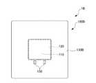
図9は、第4実施形態における携帯電話機1Cの側面図である。
以下、上述した携帯電話機1と同様の構成については説明を省略し、異なる構成を中心に説明をする。Next, a mobile phone 1C according to the fourth embodiment will be described with reference to FIG.
FIG. 9 is a side view of the mobile phone 1C according to the fourth embodiment.
Hereinafter, the description of the same configuration as that of the
図9に示すように、携帯電話機1Cは、フォルダタイプ(開閉タイプ)の携帯電話機である。携帯電話機1Cは、開状態と閉状態とに状態変更可能に構成される。 As shown in FIG. 9, the mobile phone 1C is a folder type (open / close type) mobile phone. The mobile phone 1C is configured to be changeable between an open state and a closed state.
携帯電話機1Cは、第1筐体2Cと、第2筐体3Cと、連結部4Cとを有する。
第1筐体2Cは、ケース部材20を有して構成される。
第1筐体2Cは、スピーカ部100が配置される第1面261と、第1面261と反対側の第2面262とを有する。
第1筐体2Cにおける第2面262側には、磁気センサー271(開閉センサー)が配置される。The cellular phone 1C includes a first housing 2C, a
The
The first housing 2C has a
A magnetic sensor 271 (open / close sensor) is disposed on the
第2筐体3Cは、第3面263と、第3面263と反対側の第4面264とを有する。
ここで、第2筐体3Cにおける第3面263側には、磁石272が配置される。携帯電話機1Cが閉状態において、磁石272は、磁気センサー271に近接配置される。
また、第2筐体3Cにおける第3面263側には、通話用スピーカ280が長手方向における他端側に配置される。The second housing 3 </ b> C has a
Here, the
In addition, on the
連結部4Cは、第1筐体2Cと第2筐体3Cとを回動可能に連結する。
連結部4Cは、第1筐体2Cにおける長手方向の一端側と、第2筐体3Cにおける長手方向の一端側とを連結する。
連結部4Cは、第2面262と第3面263とが近接配置される閉状態と、第2面262と第3面263とが離間して配置される開状態とに状態変更可能に第1筐体2Cと第2筐体3Cとを連結する。4 C of connection parts connect the 1st housing | casing 2C and the 2nd housing | casing 3C so that rotation is possible.
The connecting portion 4C connects one end side in the longitudinal direction of the first housing 2C and one end side in the longitudinal direction of the
The connecting portion 4C is changeable between a closed state in which the
ここで、図9に示すように、(閉状態の)携帯電話機1Cにおいて、スピーカ部100Cは、磁気センサー271及び磁石272と近い位置に配置されると共に、通話用スピーカ280とも比較的近い位置に配置される。
しかし、スピーカ部100Cは、振動部において圧電素子を用いているので、磁石を有しない構成となっている。
これにより、本実施形態によれば、携帯電話機1は、スピーカ部100Cからの磁力による悪影響を受けないので、磁気センサー271(開閉センサー)や通話用スピーカ280の配置における自由度が高い。Here, as shown in FIG. 9, in the
However, since the speaker unit 100C uses a piezoelectric element in the vibration unit, the speaker unit 100C does not have a magnet.
Thereby, according to this embodiment, since the
以上、好適な実施形態について説明したが、本発明は上述した実施形態に限定されることなく種々の形態で実施することができる。例えば、上記実施形態において、電子機器として携帯電話機1について説明しているが、これに限定されず、電子機器は、PHS(登録商標;Personal Handy phone System)、PDA(Personal Digital Assistant)、ポータブルナビゲーション装置、ノートパソコン等であってもよい。 As mentioned above, although preferred embodiment was described, this invention can be implemented with a various form, without being limited to embodiment mentioned above. For example, in the above-described embodiment, the
また、上記実施形態において、スピーカ部は、振動部として圧電素子を用いた圧電型であるが、これに限定されず、例えば、ダイナミック型等であってもよい。 Moreover, in the said embodiment, although a speaker part is a piezoelectric type which used the piezoelectric element as a vibration part, it is not limited to this, For example, a dynamic type etc. may be sufficient.
また、第1実施形態から第3実施形態において、携帯電話機は、ストレートタイプであるが、これに限定されず、例えば、第4実施形態に示す開閉タイプ(フォルダタイプ)や、開閉及び回転可能ないわゆる2軸ヒンジタイプや、操作部側筐体2と表示部側筐体3との重ね合わせた状態から一方の筐体を一方向にスライドさせるようにしたスライドタイプであってもよい。 Further, in the first to third embodiments, the mobile phone is a straight type, but is not limited to this. For example, the open / close type (folder type) shown in the fourth embodiment, or a so-called open / close and rotatable type can be used. A biaxial hinge type or a slide type in which one casing is slid in one direction from a state where the operation
1 携帯電話機
2 筐体
20 ケース部材
100 スピーカ部
110 圧電素子部(振動発生部)
120 振動板
130 フレームDESCRIPTION OF
120
Claims (7)
Translated fromJapanese前記ケース部材と一体的に成型されるスピーカ部であって、
振動発生部と、
前記振動発生部から伝達された振動により振動する振動板と、
前記振動板における外縁を保持すると共に、全部又は一部が前記ケース部材にインサート成型された保持部と、を有するスピーカ部と、を備える
電子機器。A case member made of resin at least in part,
A speaker unit molded integrally with the case member,
A vibration generating unit;
A diaphragm that vibrates due to vibrations transmitted from the vibration generator;
An electronic apparatus comprising: a speaker unit that holds an outer edge of the diaphragm and a holding unit that is entirely or partially insert-molded in the case member.
請求項1に記載の電子機器。The electronic device according to claim 1, wherein the diaphragm is waterproof.
前記保持部は、導電性部材により構成され、前記給電部に電気的に接続される被当接部を有する
請求項1又は2に記載の電子機器。A board that is housed and arranged in the case member and has a power feeding part,
The electronic device according to claim 1, wherein the holding portion includes a contacted portion that is formed of a conductive member and is electrically connected to the power feeding portion.
請求項3に記載の電子機器。The electronic device according to claim 3, wherein the holding unit is formed in a predetermined shape and functions as an antenna.
請求項1から4のいずれかに記載の電子機器。5. The electronic device according to claim 1, wherein the vibration generating unit is configured to include a piezoelectric element and is laminated on one surface of the diaphragm.
第3面と、前記第3面と反対側の第4面とを有する第2筐体と、
前記第1筐体と前記第2筐体とを回動可能に連結する連結部であって、
前記第1筐体における長手方向の一端側と前記第2筐体における長手方向の一端側とを連結すると共に、
前記第2面と前記第3面とが近接配置される閉状態と、前記第2面と前記3面とが離間して配置される開状態とに変更可能に前記第1筐体と前記第2筐体とを連結する連結部と、を備え、
前記第1筐体における第2面側には、磁気センサーが配置され、
前記第2筐体における第3面側には、磁石が前記閉状態において前記磁気センサーに近接配置される位置に配置されると共に、スピーカが前記長手方向における他端側に配置される
請求項5に記載の電子機器。A first housing having the case member and having a first surface on which the speaker unit is disposed, and a second surface opposite to the first surface;
A second housing having a third surface and a fourth surface opposite to the third surface;
A connecting portion that rotatably connects the first housing and the second housing;
While connecting one end side in the longitudinal direction of the first casing and one end side in the longitudinal direction of the second casing,
The first housing and the first surface can be changed between a closed state in which the second surface and the third surface are arranged close to each other and an open state in which the second surface and the three surfaces are arranged apart from each other. A connecting portion for connecting the two housings,
A magnetic sensor is disposed on the second surface side of the first housing,
6. The third surface side of the second housing is disposed at a position where a magnet is disposed close to the magnetic sensor in the closed state, and a speaker is disposed on the other end side in the longitudinal direction. The electronic device as described in.
請求項1から4のいずれかに記載の電子機器。5. The holding unit according to claim 1, wherein an area of the holding unit viewed from a direction perpendicular to the diaphragm is larger than an area of the diaphragm surrounded by the holding unit viewed from the direction of the perpendicular. The electronic device as described in.
Priority Applications (2)
| Application Number | Priority Date | Filing Date | Title |
|---|---|---|---|
| JP2011065463AJP5576821B2 (en) | 2011-03-24 | 2011-03-24 | Electronics |
| US13/426,221US8611945B2 (en) | 2011-03-24 | 2012-03-21 | Electronic device |
Applications Claiming Priority (1)
| Application Number | Priority Date | Filing Date | Title |
|---|---|---|---|
| JP2011065463AJP5576821B2 (en) | 2011-03-24 | 2011-03-24 | Electronics |
Publications (2)
| Publication Number | Publication Date |
|---|---|
| JP2012204913A JP2012204913A (en) | 2012-10-22 |
| JP5576821B2true JP5576821B2 (en) | 2014-08-20 |
Family
ID=46877779
Family Applications (1)
| Application Number | Title | Priority Date | Filing Date |
|---|---|---|---|
| JP2011065463AExpired - Fee RelatedJP5576821B2 (en) | 2011-03-24 | 2011-03-24 | Electronics |
Country Status (2)
| Country | Link |
|---|---|
| US (1) | US8611945B2 (en) |
| JP (1) | JP5576821B2 (en) |
Families Citing this family (15)
| Publication number | Priority date | Publication date | Assignee | Title |
|---|---|---|---|---|
| KR101771454B1 (en)* | 2010-09-03 | 2017-08-25 | 엘지전자 주식회사 | Mobile terminal and method of fabricating case thereof |
| USD694730S1 (en)* | 2012-08-27 | 2013-12-03 | Lg Electronics Inc. | Mobile phone |
| GB2508364B (en)* | 2012-11-28 | 2015-10-21 | Entangle Ltd | Audio device housing with reconfigurable sound producing capabilities |
| JP6022967B2 (en)* | 2013-02-22 | 2016-11-09 | 京セラ株式会社 | Vibration device, electronic device, and portable terminal |
| JP6193743B2 (en)* | 2013-11-25 | 2017-09-06 | 京セラ株式会社 | Mobile device |
| JP6283505B2 (en)* | 2013-11-25 | 2018-02-21 | 京セラ株式会社 | Mobile device |
| EP3091755A4 (en) | 2013-12-31 | 2017-09-20 | Innochips Technology Co., Ltd. | Portable piezoelectric speaker and electronic device having same |
| KR101877503B1 (en)* | 2015-12-24 | 2018-07-11 | 주식회사 모다이노칩 | Complex device and electronic device having the same |
| KR102520709B1 (en) | 2016-04-19 | 2023-04-12 | 삼성디스플레이 주식회사 | Protection tape for printed circuit board and display apparatus comprising the same |
| DE102018121322A1 (en)* | 2018-08-31 | 2020-03-05 | Heyco IML Kunststofftechnik GmbH&Co.KG | Method for producing a component for a motor vehicle, and corresponding component |
| CN109246260B (en)* | 2018-09-11 | 2020-07-03 | Oppo广东移动通信有限公司 | Mobile terminal and shell assembly thereof |
| CN109362009B (en)* | 2018-10-29 | 2021-03-26 | Oppo广东移动通信有限公司 | electronic device |
| CN111698585A (en)* | 2019-03-14 | 2020-09-22 | 深圳市伊声声学科技有限公司 | Waterproof ventilative board that shakes and have this micro loudspeaker that shakes board |
| EP3968515B1 (en)* | 2020-09-09 | 2024-12-04 | Shenzhen Goodix Technology Co., Ltd. | Driver circuit arrangement for high capacitive load |
| EP4597254A1 (en)* | 2022-11-22 | 2025-08-06 | Samsung Electronics Co., Ltd. | Wearable electronic device comprising conductive pin |
Family Cites Families (12)
| Publication number | Priority date | Publication date | Assignee | Title |
|---|---|---|---|---|
| JPS5554068Y2 (en)* | 1974-04-30 | 1980-12-15 | ||
| JP2000201399A (en) | 1998-11-02 | 2000-07-18 | Matsushita Electric Ind Co Ltd | Piezoelectric speaker |
| KR20010055059A (en)* | 1999-12-09 | 2001-07-02 | 윤종용 | Hall switch in wireless telephone set |
| US6834181B2 (en)* | 2002-03-13 | 2004-12-21 | Nokia Corporation | Mobile communication device and related construction method |
| US20040203503A1 (en)* | 2002-05-31 | 2004-10-14 | Rollins Thomas James | Portable electronic apparatus |
| JP2004015768A (en)* | 2002-06-12 | 2004-01-15 | Murata Mfg Co Ltd | Piezoelectric electroacoustic transducer |
| US7228158B2 (en)* | 2002-11-12 | 2007-06-05 | Samsung Electronics Co., Ltd. | Portable terminal capable of providing stereo sound |
| WO2006011604A1 (en)* | 2004-07-30 | 2006-02-02 | Matsushita Electric Industrial Co., Ltd. | Loudspeaker system, mobile terminal device, an electronic device |
| JP3966320B2 (en)* | 2004-09-28 | 2007-08-29 | セイコーエプソン株式会社 | Electro-optical device and electronic apparatus |
| JP2007074062A (en)* | 2005-09-05 | 2007-03-22 | Citizen Electronics Co Ltd | Exciter for panel speaker and panel speaker |
| JP4215788B2 (en)* | 2006-08-25 | 2009-01-28 | ホシデン株式会社 | Piezoelectric electroacoustic transducer |
| JP2009188801A (en)* | 2008-02-07 | 2009-08-20 | Panasonic Corp | Piezoelectric speaker |
- 2011
- 2011-03-24JPJP2011065463Apatent/JP5576821B2/ennot_activeExpired - Fee Related
- 2012
- 2012-03-21USUS13/426,221patent/US8611945B2/ennot_activeExpired - Fee Related
Also Published As
| Publication number | Publication date |
|---|---|
| US8611945B2 (en) | 2013-12-17 |
| US20120244912A1 (en) | 2012-09-27 |
| JP2012204913A (en) | 2012-10-22 |
Similar Documents
| Publication | Publication Date | Title |
|---|---|---|
| JP5576821B2 (en) | Electronics | |
| US8774876B2 (en) | Mobile electronic device | |
| US8482697B2 (en) | Protecting module and portable electronic device using the same | |
| EP2773083B1 (en) | Fixation of the battery with a metal plate to the housing of an electronic device | |
| EP3817355B1 (en) | Camera module and optical device including same | |
| US20130265504A1 (en) | Television and electronic apparatus | |
| JP2006186691A (en) | Dust-proof structure and dust-proof method in electronic equipment, and electronic equipment | |
| JP4833130B2 (en) | Electronics | |
| JP2011155520A (en) | Mobile electronic equipment | |
| US20130265505A1 (en) | Television and electronic apparatus | |
| JP5085223B2 (en) | Electronics | |
| JP2013115615A (en) | Electronic apparatus | |
| JP5063186B2 (en) | Mobile terminal device | |
| JP5202414B2 (en) | Portable electronic devices | |
| JP4436292B2 (en) | Electronics | |
| JP4994114B2 (en) | Mobile terminal device | |
| JP2011040853A (en) | Portable terminal device | |
| JP2009081751A (en) | Portable device | |
| JP5368133B2 (en) | Electronics | |
| JP5361068B2 (en) | Portable electronic devices | |
| JP2013187884A (en) | Portable terminal device | |
| JP2009060293A (en) | Portable electronic devices | |
| JP4699405B2 (en) | Portable electronic devices | |
| JP5197435B2 (en) | Electronics | |
| JP5335537B2 (en) | Portable electronic devices |
Legal Events
| Date | Code | Title | Description |
|---|---|---|---|
| RD04 | Notification of resignation of power of attorney | Free format text:JAPANESE INTERMEDIATE CODE: A7424 Effective date:20120803 | |
| A621 | Written request for application examination | Free format text:JAPANESE INTERMEDIATE CODE: A621 Effective date:20140115 | |
| A977 | Report on retrieval | Free format text:JAPANESE INTERMEDIATE CODE: A971007 Effective date:20140618 | |
| TRDD | Decision of grant or rejection written | ||
| A01 | Written decision to grant a patent or to grant a registration (utility model) | Free format text:JAPANESE INTERMEDIATE CODE: A01 Effective date:20140624 | |
| A61 | First payment of annual fees (during grant procedure) | Free format text:JAPANESE INTERMEDIATE CODE: A61 Effective date:20140704 | |
| R150 | Certificate of patent or registration of utility model | Ref document number:5576821 Country of ref document:JP Free format text:JAPANESE INTERMEDIATE CODE: R150 | |
| LAPS | Cancellation because of no payment of annual fees |