JP5575431B2 - Single axis sensor on flexible backbone - Google Patents
Single axis sensor on flexible backboneDownload PDFInfo
- Publication number
- JP5575431B2 JP5575431B2JP2009182073AJP2009182073AJP5575431B2JP 5575431 B2JP5575431 B2JP 5575431B2JP 2009182073 AJP2009182073 AJP 2009182073AJP 2009182073 AJP2009182073 AJP 2009182073AJP 5575431 B2JP5575431 B2JP 5575431B2
- Authority
- JP
- Japan
- Prior art keywords
- coil
- probe
- coils
- wire
- signal processing
- Prior art date
- Legal status (The legal status is an assumption and is not a legal conclusion. Google has not performed a legal analysis and makes no representation as to the accuracy of the status listed.)
- Active
Links
Images


Classifications
- G—PHYSICS
- G01—MEASURING; TESTING
- G01R—MEASURING ELECTRIC VARIABLES; MEASURING MAGNETIC VARIABLES
- G01R33/00—Arrangements or instruments for measuring magnetic variables
- G01R33/20—Arrangements or instruments for measuring magnetic variables involving magnetic resonance
- G01R33/28—Details of apparatus provided for in groups G01R33/44 - G01R33/64
- G01R33/32—Excitation or detection systems, e.g. using radio frequency signals
- G01R33/34—Constructional details, e.g. resonators, specially adapted to MR
- G01R33/34084—Constructional details, e.g. resonators, specially adapted to MR implantable coils or coils being geometrically adaptable to the sample, e.g. flexible coils or coils comprising mutually movable parts
- A—HUMAN NECESSITIES
- A61—MEDICAL OR VETERINARY SCIENCE; HYGIENE
- A61B—DIAGNOSIS; SURGERY; IDENTIFICATION
- A61B5/00—Measuring for diagnostic purposes; Identification of persons
- A61B5/24—Detecting, measuring or recording bioelectric or biomagnetic signals of the body or parts thereof
- A61B5/25—Bioelectric electrodes therefor
- A61B5/279—Bioelectric electrodes therefor specially adapted for particular uses
- A61B5/28—Bioelectric electrodes therefor specially adapted for particular uses for electrocardiography [ECG]
- A61B5/283—Invasive
- A—HUMAN NECESSITIES
- A61—MEDICAL OR VETERINARY SCIENCE; HYGIENE
- A61B—DIAGNOSIS; SURGERY; IDENTIFICATION
- A61B34/00—Computer-aided surgery; Manipulators or robots specially adapted for use in surgery
- A61B34/20—Surgical navigation systems; Devices for tracking or guiding surgical instruments, e.g. for frameless stereotaxis
- A—HUMAN NECESSITIES
- A61—MEDICAL OR VETERINARY SCIENCE; HYGIENE
- A61B—DIAGNOSIS; SURGERY; IDENTIFICATION
- A61B5/00—Measuring for diagnostic purposes; Identification of persons
- A61B5/06—Devices, other than using radiation, for detecting or locating foreign bodies ; Determining position of diagnostic devices within or on the body of the patient
- A61B5/061—Determining position of a probe within the body employing means separate from the probe, e.g. sensing internal probe position employing impedance electrodes on the surface of the body
- A61B5/062—Determining position of a probe within the body employing means separate from the probe, e.g. sensing internal probe position employing impedance electrodes on the surface of the body using magnetic field
- A—HUMAN NECESSITIES
- A61—MEDICAL OR VETERINARY SCIENCE; HYGIENE
- A61B—DIAGNOSIS; SURGERY; IDENTIFICATION
- A61B5/00—Measuring for diagnostic purposes; Identification of persons
- A61B5/06—Devices, other than using radiation, for detecting or locating foreign bodies ; Determining position of diagnostic devices within or on the body of the patient
- A61B5/065—Determining position of the probe employing exclusively positioning means located on or in the probe, e.g. using position sensors arranged on the probe
- A—HUMAN NECESSITIES
- A61—MEDICAL OR VETERINARY SCIENCE; HYGIENE
- A61B—DIAGNOSIS; SURGERY; IDENTIFICATION
- A61B5/00—Measuring for diagnostic purposes; Identification of persons
- A61B5/68—Arrangements of detecting, measuring or recording means, e.g. sensors, in relation to patient
- A61B5/6846—Arrangements of detecting, measuring or recording means, e.g. sensors, in relation to patient specially adapted to be brought in contact with an internal body part, i.e. invasive
- A61B5/6847—Arrangements of detecting, measuring or recording means, e.g. sensors, in relation to patient specially adapted to be brought in contact with an internal body part, i.e. invasive mounted on an invasive device
- A61B5/6852—Catheters
- A61B5/6859—Catheters with multiple distal splines
- A—HUMAN NECESSITIES
- A61—MEDICAL OR VETERINARY SCIENCE; HYGIENE
- A61M—DEVICES FOR INTRODUCING MEDIA INTO, OR ONTO, THE BODY; DEVICES FOR TRANSDUCING BODY MEDIA OR FOR TAKING MEDIA FROM THE BODY; DEVICES FOR PRODUCING OR ENDING SLEEP OR STUPOR
- A61M25/00—Catheters; Hollow probes
- A61M25/01—Introducing, guiding, advancing, emplacing or holding catheters
- A61M25/0105—Steering means as part of the catheter or advancing means; Markers for positioning
- A61M25/0127—Magnetic means; Magnetic markers
- B—PERFORMING OPERATIONS; TRANSPORTING
- B32—LAYERED PRODUCTS
- B32B—LAYERED PRODUCTS, i.e. PRODUCTS BUILT-UP OF STRATA OF FLAT OR NON-FLAT, e.g. CELLULAR OR HONEYCOMB, FORM
- B32B1/00—Layered products having a non-planar shape
- A—HUMAN NECESSITIES
- A61—MEDICAL OR VETERINARY SCIENCE; HYGIENE
- A61B—DIAGNOSIS; SURGERY; IDENTIFICATION
- A61B34/00—Computer-aided surgery; Manipulators or robots specially adapted for use in surgery
- A61B34/20—Surgical navigation systems; Devices for tracking or guiding surgical instruments, e.g. for frameless stereotaxis
- A61B2034/2046—Tracking techniques
- A61B2034/2051—Electromagnetic tracking systems
- A—HUMAN NECESSITIES
- A61—MEDICAL OR VETERINARY SCIENCE; HYGIENE
- A61B—DIAGNOSIS; SURGERY; IDENTIFICATION
- A61B34/00—Computer-aided surgery; Manipulators or robots specially adapted for use in surgery
- A61B34/20—Surgical navigation systems; Devices for tracking or guiding surgical instruments, e.g. for frameless stereotaxis
- A61B2034/2072—Reference field transducer attached to an instrument or patient
- A—HUMAN NECESSITIES
- A61—MEDICAL OR VETERINARY SCIENCE; HYGIENE
- A61M—DEVICES FOR INTRODUCING MEDIA INTO, OR ONTO, THE BODY; DEVICES FOR TRANSDUCING BODY MEDIA OR FOR TAKING MEDIA FROM THE BODY; DEVICES FOR PRODUCING OR ENDING SLEEP OR STUPOR
- A61M25/00—Catheters; Hollow probes
- A61M25/01—Introducing, guiding, advancing, emplacing or holding catheters
- A61M25/0105—Steering means as part of the catheter or advancing means; Markers for positioning
- A61M2025/0166—Sensors, electrodes or the like for guiding the catheter to a target zone, e.g. image guided or magnetically guided
- G—PHYSICS
- G01—MEASURING; TESTING
- G01R—MEASURING ELECTRIC VARIABLES; MEASURING MAGNETIC VARIABLES
- G01R33/00—Arrangements or instruments for measuring magnetic variables
- G01R33/20—Arrangements or instruments for measuring magnetic variables involving magnetic resonance
- G01R33/28—Details of apparatus provided for in groups G01R33/44 - G01R33/64
- G01R33/285—Invasive instruments, e.g. catheters or biopsy needles, specially adapted for tracking, guiding or visualization by NMR
- G01R33/287—Invasive instruments, e.g. catheters or biopsy needles, specially adapted for tracking, guiding or visualization by NMR involving active visualization of interventional instruments, e.g. using active tracking RF coils or coils for intentionally creating magnetic field inhomogeneities
- Y—GENERAL TAGGING OF NEW TECHNOLOGICAL DEVELOPMENTS; GENERAL TAGGING OF CROSS-SECTIONAL TECHNOLOGIES SPANNING OVER SEVERAL SECTIONS OF THE IPC; TECHNICAL SUBJECTS COVERED BY FORMER USPC CROSS-REFERENCE ART COLLECTIONS [XRACs] AND DIGESTS
- Y10—TECHNICAL SUBJECTS COVERED BY FORMER USPC
- Y10T—TECHNICAL SUBJECTS COVERED BY FORMER US CLASSIFICATION
- Y10T29/00—Metal working
- Y10T29/49—Method of mechanical manufacture
- Y10T29/49002—Electrical device making
- Y10T29/4902—Electromagnet, transformer or inductor
Landscapes
- Health & Medical Sciences (AREA)
- Life Sciences & Earth Sciences (AREA)
- Engineering & Computer Science (AREA)
- Surgery (AREA)
- Public Health (AREA)
- General Health & Medical Sciences (AREA)
- Veterinary Medicine (AREA)
- Biomedical Technology (AREA)
- Heart & Thoracic Surgery (AREA)
- Animal Behavior & Ethology (AREA)
- Medical Informatics (AREA)
- Molecular Biology (AREA)
- Physics & Mathematics (AREA)
- Biophysics (AREA)
- Pathology (AREA)
- Human Computer Interaction (AREA)
- Nuclear Medicine, Radiotherapy & Molecular Imaging (AREA)
- Robotics (AREA)
- Hematology (AREA)
- Anesthesiology (AREA)
- Pulmonology (AREA)
- Condensed Matter Physics & Semiconductors (AREA)
- General Physics & Mathematics (AREA)
- Cardiology (AREA)
- Mechanical Engineering (AREA)
- Media Introduction/Drainage Providing Device (AREA)
- Measurement And Recording Of Electrical Phenomena And Electrical Characteristics Of The Living Body (AREA)
- Magnetic Resonance Imaging Apparatus (AREA)
- Measurement Of Length, Angles, Or The Like Using Electric Or Magnetic Means (AREA)
Description
Translated fromJapanese〔発明の背景〕
〔発明の分野〕
本発明は、侵襲的な医療装置に関する。より詳細には、本発明は、身体内部での侵襲的な医療用プローブの位置測定(localization)に関する。BACKGROUND OF THE INVENTION
(Field of the Invention)
The present invention relates to an invasive medical device. More particularly, the present invention relates to localization of invasive medical probes inside the body.
〔関連技術の説明〕
様々な医療処置および内部画像化に適している、カテーテルなどのプローブは、現在、一般的である。そのようなプローブは、血管形成カテーテル、レーザー特性、電気的特性もしくは凍結融解壊死治療特性を備えたカテーテル、超音波画像化ヘッドを有するカテーテル、ほぼ切開のない手術もしくは診断に使用されるプローブ、および内視鏡を含む。[Description of related technology]
Probes such as catheters that are suitable for various medical procedures and internal imaging are now common. Such probes include an angioplasty catheter, a catheter with laser characteristics, electrical characteristics or freeze thaw necrosis treatment characteristics, a catheter with an ultrasound imaging head, a probe used for surgery or diagnosis with almost no incision, and Includes an endoscope.
そのようなプローブが治療に使用される場合、プローブは、身体構造体に関して慎重に置かれなければならない。1つの適用では、電気生理学的センサを含む心臓カテーテルが、心臓の電気的活動をマッピングすることで知られている。典型的には、心内膜の時変電位(time-varying electrical potentials)は、心臓の内側での位置の関数として感知および記録されて、その後、局所電位図または局所興奮到達時間(local activation time)をマッピングするのに使用される。興奮到達時間は、心筋を通した電気インパルスの伝導に必要とされる時間のため、心内膜における点ごとに異なる。心臓の任意の点におけるこの電気伝導の方向は、慣習的には、等電活動面(isoelectric activation front)に対して垂直である活性化ベクトルによって表され、等電活動面および活性化ベクトルの双方は、興奮到達時間のマップから導き出すことができる。心内膜の任意の点を通る活動面の伝播速度を、速度ベクトルとして表すことができる。 When such a probe is used for therapy, the probe must be carefully placed with respect to the body structure. In one application, cardiac catheters containing electrophysiological sensors are known for mapping cardiac electrical activity. Typically, endocardial time-varying electrical potentials are sensed and recorded as a function of position inside the heart, followed by local electrograms or local activation times. ) Is used for mapping. Excitation arrival time varies from point to point in the endocardium due to the time required for conduction of electrical impulses through the myocardium. This direction of electrical conduction at any point in the heart is conventionally represented by an activation vector that is perpendicular to the isoelectric activation front, both the isoelectric activity surface and the activation vector. Can be derived from the excitement arrival time map. The propagation velocity of the active surface through any point of the endocardium can be expressed as a velocity vector.
活動面および伝導場をマッピングすることは、医師が、心臓組織における電気伝播が損なわれた領域に起因する、心室頻拍および心房頻拍ならびに心室細動および心房細動などの異常を識別および診断するのを支援する。 Mapping active surfaces and conduction fields allows physicians to identify and diagnose abnormalities such as ventricular tachycardia and atrial tachycardia and ventricular fibrillation and atrial fibrillation resulting from areas of impaired electrical transmission in cardiac tissue To help.
心臓の活性化信号伝導における局所的欠損は、複数の活動面、活性化ベクトルの異常な集中、または、正常値からの速度ベクトルの変化もしくは正常値からのベクトルの逸脱などの現象を観察することによって、識別されることができる。その上、例えば局所的な梗塞のため、機能するのをやめてしまった心筋の欠損部分内部に電気伝播が全くない場合がある。欠損がそのようなマッピングによって位置を突き止められると、可能な限り心臓の正常な機能を回復するように、欠損は(この欠損が異常に機能している場合は)切除されてよく、または、別様に治療されてよい。 Local deficits in the activation signal conduction of the heart are to observe phenomena such as multiple activity planes, abnormal concentration of activation vectors, or velocity vector changes from normal values or vector deviations from normal values Can be identified. In addition, there may be no electrical propagation at all within the myocardial defect that has ceased functioning, for example due to local infarction. Once the defect is located by such mapping, the defect may be excised (if the defect is functioning abnormally), or otherwise, so as to restore the normal functioning of the heart as much as possible. May be treated in the same way.
心筋における電気的興奮到達時間のマッピングは、心臓内部のセンサの場所が各測定時点で知られていることを必要とする。これまで、そのようなマッピングは、心臓の内側で単一の可動電極センサを使用して実行された。このセンサは、固定された外部基準電極に対する興奮到達時間を測定した。しかしながら、この技術は、較正、例えば身体のインピーダンスに関係ないインピーダンスの調節によるインピーダンス較正、を必要とする。その上、単一の電極を使用した電気的興奮到達時間のマッピングは、長い処置であり、一般に、X線透視検査による画像化の下で実行されなければならず、それにより、望ましくないイオン化放射線に患者をさらす。さらに、不整脈の心臓では、単一の場所での興奮到達時間は、連続した拍動間で変わる場合がある。 Mapping of electrical excitation arrival times in the myocardium requires that the location of sensors within the heart be known at each measurement time. So far, such mapping has been performed using a single movable electrode sensor inside the heart. This sensor measured the excitation arrival time for a fixed external reference electrode. However, this technique requires calibration, for example, impedance calibration by adjusting impedance independent of body impedance. Moreover, mapping electrical excitement arrival times using a single electrode is a long procedure and generally must be performed under fluoroscopic imaging, thereby causing unwanted ionizing radiation. Expose the patient to. Furthermore, in an arrhythmic heart, the excitement arrival time at a single location may vary between successive beats.
単一電極によるマッピングの欠点のため、多くの発明者が、心内膜の異なる場所で電位を同時に測定するための複数の電極の使用を教示し、それにより、興奮到達時間が、前述のように、より迅速かつ便利にマッピングされることができるようになった。例えば、参照により本明細書に組み込まれるPCT特許公開第WO97/24983号(Ben-Haim)は、3つの非共線電極がカテーテルの遠位端部において実質的に剛性のリングに取り付けられる構造であって、電極によって定められた平面における電気的活性化ベクトルの方向が完全に決定されうるようになっている、構造を記載している。 Because of the drawbacks of single electrode mapping, many inventors teach the use of multiple electrodes to simultaneously measure potentials at different locations in the endocardium, so that the excitement arrival time is as described above. Can be mapped more quickly and conveniently. For example, PCT Patent Publication No. WO 97/24983 (Ben-Haim), incorporated herein by reference, is a structure in which three non-collinear electrodes are attached to a substantially rigid ring at the distal end of the catheter. A structure is described in which the direction of the electrical activation vector in the plane defined by the electrodes can be completely determined.
開示内容が参照により本明細書に組み込まれるPCT特許公開第WO96/05768号は、カテーテルの遠位端部で固定された、小型で、好ましくは非同心の、複数のセンサコイルを含む、位置応答性カテーテルを記載している。外部で印加された磁場に応答してこれらのコイルにより発生する電気的信号は、コイルの6次元の位置座標および向き座標を決定するために分析される。 PCT Patent Publication No. WO 96/05768, the disclosure of which is incorporated herein by reference, is a position response comprising a plurality of small, preferably non-concentric, sensor coils fixed at the distal end of a catheter. A catheter is described. The electrical signals generated by these coils in response to an externally applied magnetic field are analyzed to determine the six-dimensional position and orientation coordinates of the coils.
参照により本明細書に組み込まれる、Ben-Haimに発行された米国特許第6,272,371号は、遠位端部に対して既知の位置でプローブの遠位部分に固定されている、複数のセンサを開示しており、これらセンサは、プローブの屈曲に応答する信号を発生させる。信号処理回路網が、屈曲応答性信号を受信し、それらの信号を処理して、少なくとも第1のセンサの位置座標および向き座標を見つけ、かつ、プローブの遠位部分の長さに沿った複数の点の場所を決定する。 US Pat. No. 6,272,371 issued to Ben-Haim, incorporated herein by reference, is a plurality of fixed to the distal portion of the probe at a known location relative to the distal end. These sensors generate signals that are responsive to probe bending. A signal processing circuitry receives the flex response signals and processes them to find at least the position and orientation coordinates of the first sensor and a plurality along the length of the distal portion of the probe Determine the location of the point.
〔発明の概要〕
前記の適用で述べたように、カテーテルまたは他のプローブの長さに沿った複数の場所におけるセンサから位置測定値を得ることは、しばしば有用である。しかしながら、多くの場合、プローブの進行(navigation)、および測定は、位置感知コイルのサイズと、場所が感知されることになっているプローブのまさしくその部分にコイルを収容する必要性と、によって妨げられる。[Summary of the Invention]
As noted in the above applications, it is often useful to obtain position measurements from sensors at multiple locations along the length of a catheter or other probe. However, in many cases, probe navigation and measurement is hampered by the size of the position sensing coil and the need to house the coil in the very part of the probe where the location is to be sensed. It is done.
本発明の開示された実施形態によると、狭いプローブは、生きている被験者の身体に挿入されるように構成されている。プローブは、可撓性であってよく、プローブのバックボーンに巻き付けられた非常に細いワイヤのシングルコイルから成る複数のセンサを有する。複数のセンサは、細い接続ワイヤを通じて位置プロセッサへと近位に信号を送信する。位置プロセッサは、プローブの長さに沿った複数の点で位置座標を決定するために信号を分析する。プローブは、直交する感知コイルも特別な較正処置も必要とせず、従来のプローブより直径を小さくして実際に製造されることができる。これらの技術は、あらゆるタイプのカテーテル、および電極の位置を決定するための要件に適用可能である。 According to the disclosed embodiments of the present invention, the narrow probe is configured to be inserted into the body of a living subject. The probe may be flexible and has multiple sensors consisting of a single coil of very thin wire wrapped around the probe backbone. The plurality of sensors transmit signals proximally to the position processor through thin connection wires. The position processor analyzes the signal to determine position coordinates at a plurality of points along the length of the probe. The probe does not require orthogonal sensing coils or special calibration procedures and can actually be manufactured with a smaller diameter than conventional probes. These techniques are applicable to all types of catheters and requirements for determining the position of the electrodes.
本発明のある実施形態は、被験者の身体に挿入されるよう構成された遠位端部を有する、細長い可撓性プローブと、プローブ上の基準場所に対して既知の関係で、種々のそれぞれの点で固定された複数のコイルと、を含む、侵襲的な医療用プローブ装置を提供する。外部で印加された磁場にさらされると、コイルは、コイルの位置座標に応答して、それぞれの信号を発生させる。装置は、信号処理回路網を含み、信号処理回路網は、その信号を受信し、信号を処理して、プローブの一部に沿った点のそれぞれの場所を決定する。 Certain embodiments of the present invention include an elongate flexible probe having a distal end configured to be inserted into a subject's body and a variety of each in a known relationship to a reference location on the probe. An invasive medical probe device is provided that includes a plurality of coils fixed at points. When exposed to an externally applied magnetic field, the coils generate respective signals in response to the position coordinates of the coils. The apparatus includes signal processing circuitry that receives the signal and processes the signal to determine the location of each of the points along a portion of the probe.
装置の一態様によると、コイルは、プローブの近位セグメントにコイルを取り付ける可撓性接続ワイヤによって支持される。 According to one aspect of the device, the coil is supported by a flexible connecting wire that attaches the coil to the proximal segment of the probe.
装置のさらなる態様によると、プローブの遠位セグメントは、複数の可撓性分岐部に分かれ、コイルは、それら分岐部上に分配される。 According to a further aspect of the device, the distal segment of the probe is divided into a plurality of flexible branches, and the coil is distributed on the branches.
装置のさらに別の態様によると、コイルは、8〜70μmの範囲の直径を有するワイヤで形成される。 According to yet another aspect of the device, the coil is formed of a wire having a diameter in the range of 8-70 μm.
装置の一態様によると、コイルは、直径が15μmを超えないワイヤで形成される。 According to one aspect of the device, the coil is formed of a wire having a diameter not exceeding 15 μm.
装置のさらに別の態様によると、コイルは、直径が10μmを超えないワイヤで形成される。 According to yet another aspect of the device, the coil is formed of wire that does not exceed 10 μm in diameter.
装置の追加の態様によると、プローブの直径は、8フレンチ(2.7mm)を超えない。 According to an additional aspect of the device, the diameter of the probe does not exceed 8 French (2.7 mm).
装置の一態様によると、プローブは、内部の長さ方向バックボーンを有し、コイルは、バックボーンの周りに螺旋状に配され、バックボーンの上で支えられている。 According to one aspect of the apparatus, the probe has an internal longitudinal backbone and the coil is helically disposed about and supported on the backbone.
装置のさらに別の態様によると、コイルは、バックボーンに沿って延びるそれぞれのワイヤによって信号処理回路網に接続される。 According to yet another aspect of the apparatus, the coils are connected to the signal processing circuitry by respective wires extending along the backbone.
装置の態様によると、バックボーンは、長さ方向に孔のない材料(longitudinally non-perforate material)で形成される。 According to an embodiment of the device, the backbone is formed of a longitudinally non-perforate material.
装置のさらなる態様によると、バックボーンは、強磁性材料を含む。 According to a further aspect of the device, the backbone comprises a ferromagnetic material.
装置のさらに別の態様によると、バックボーンは、中央内腔を有する。 According to yet another aspect of the device, the backbone has a central lumen.
装置のさらに別の態様によると、信号処理回路網は、6次元でコイルの並進座標および向き座標(translational and orientational coordinates)を決定するように作用する。 According to yet another aspect of the apparatus, the signal processing circuitry is operative to determine translational and orientational coordinates of the coil in six dimensions.
装置の追加の態様によると、信号処理回路網は、プローブの曲げ角度を決定するように作用する。 According to an additional aspect of the apparatus, the signal processing circuitry serves to determine the bending angle of the probe.
装置の追加の態様によると、信号処理回路網は、プローブの遠位部分の曲率半径を決定するように作用する。 According to an additional aspect of the device, the signal processing circuitry serves to determine the radius of curvature of the distal portion of the probe.
本発明の他の態様は、前述した装置によって実行される方法を提供する。 Another aspect of the invention provides a method performed by the apparatus described above.
本発明のある実施形態は、侵襲的な医療用プローブを作る方法を提供し、この方法は、細長い可撓性プローブに内部の長さ方向バックボーンを設けること、バックボーンの周りに複数のコイルを配することによって実行され、コイルは、プローブの遠位端部に対して既知の関係で、種々のそれぞれの点で固定されている。この方法は、コイルを信号処理回路網に接続するためにそれぞれの接続ワイヤをコイルに取り付けること、ならびに、接続ワイヤおよびバックボーンの周りで外層を貼り付けることによって、さらに実行される。 Certain embodiments of the present invention provide a method of making an invasive medical probe that includes providing an elongate flexible probe with an internal longitudinal backbone and arranging a plurality of coils around the backbone. The coil is fixed at various points in a known relationship to the distal end of the probe. This method is further performed by attaching each connection wire to the coil to connect the coil to the signal processing circuitry and affixing an outer layer around the connection wire and backbone.
この方法のある態様は、バックボーンにコイルを巻き付けることによって、実行される。 One aspect of this method is performed by winding a coil around the backbone.
この方法の別の態様は、コイルを予め形成して、その予め形成されたコイルをバックボーンの上へ滑らせることによって、実行される。 Another aspect of this method is performed by preforming the coil and sliding the preformed coil over the backbone.
この方法のさらなる態様は、バックボーンを複数の分岐部に分けて、コイルをその分岐部上に分配することによって、実行される。 A further aspect of this method is performed by dividing the backbone into a plurality of branches and distributing the coils on the branches.
本発明のより良い理解のため、例として、発明の詳細な説明を参照する。この詳細な説明は、同様の要素が同様の参照符号を与えられている以下の図面と併せて読まれるべきものである。 For a better understanding of the present invention, reference is made to the detailed description of the invention by way of example. This detailed description should be read in conjunction with the following drawings, in which like elements are given like reference numerals.
〔発明の詳細な説明〕
以下の説明では、本発明の徹底的な理解を提供するために、多数の具体的な細目が説明される。しかしながら、本発明がこれらの具体的な細目なしでも実施されうることは、当業者には明らかであろう。他の例では、従来のアルゴリズムおよび処理のためのコンピュータプログラム命令の周知の回路、制御論理、および細目は、本発明を不必要に曖昧にしないよう、詳細に示されてはいない。Detailed Description of the Invention
In the following description, numerous specific details are set forth in order to provide a thorough understanding of the present invention. However, it will be apparent to those skilled in the art that the present invention may be practiced without these specific details. In other instances, well-known circuits, control logic, and details of computer program instructions for conventional algorithms and processing have not been shown in detail so as not to unnecessarily obscure the present invention.
図面に目を向け、まず図1を参照する。図1は、本発明の開示された実施形態による、屈曲応答性プローブまたはカテーテル10を示す。カテーテル10は、好ましくは被験者の心臓に挿入される遠位端部12と、制御コンソール16に連結された近位端部14と、を含む。カテーテル10は、本発明の原理を適用するために改造された、例えば、カリフォルニア州91765ダイアモンド・バー、ダイアモンド・キャニオン・ロード3333所在のBiosense Webster, Inc.から入手可能なLASSO円形マッピングカテーテルであってよい。 Turning to the drawing, reference is first made to FIG. FIG. 1 illustrates a flex responsive probe or
遠位端部12に隣接して、磁場に応答して位置信号を生じさせるセンサがある。前記のPCT公開WO96/05768号は、場の発生器18により印加されるような磁場の生成を開示している。センサの信号は、ワイヤ(図1には示されていない)により、または無線で、制御コンソール16の信号処理・計算回路網20に運ばれ、信号処理・計算回路網20はまた、好ましくは、駆動信号および制御信号を場の発生器18に与える。回路網20は、場の発生器18によって確立された座標系(frame of reference)に関連して、コイル22の6次元の並進座標および向き座標を決定するために、前記のPCT公開でさらに説明されているように、信号を分析する。コイル22は、カテーテル10上の基準点に対する既知のそれぞれの場所、例えば、遠位端部12、または、多分岐の実施形態(以下で説明する)の場合はカテーテル10の本体上の分岐点、に配される。 Adjacent to the distal end 12 is a sensor that generates a position signal in response to a magnetic field. Said PCT publication WO 96/05768 discloses the generation of a magnetic field as applied by a
カテーテル10は、従来の外層24を含み、外層24は、例えば軟質プラスチック製ロッドであってよい、内部の可撓性バックボーン26の上に貼り付けられる。代わりに、バックボーン26は、強磁性材料で作られることができる。
複数の1軸感知コイル22は、バックボーン26の周りで螺旋状に配されて、バックボーン26によって、例えばコイルをバックボーン26に巻き付けることによって、支えられており、ワイヤ28によって回路網20に接続される。代わりに、コイル22は、予め形成され、バックボーン26の上に滑らせることができる。コイル22および接続ワイヤ28は、直径が約10μmのワイヤで形成される。ワイヤは、異なる適用において8〜70μmの範囲であってよい。ワイヤ28は、近位に延びるにつれて、バックボーン26の周りで螺旋状であるのが好ましい。従来の直交コイルが使用されないので、カテーテルは、直径が8フレンチ(2.7mm)未満であってよい。実際、前述した技術を使用して、0.5mmと小さい外径を有するプローブを構築することが可能である。バックボーン26が強磁性材料で作られている場合、コイル22のゲインは増加される。 A plurality of uniaxial sensing coils 22 are arranged in a spiral around the
コイル22はそれぞれ、場の発生器18により発生される磁場の座標系に対する、コイルの位置を示す信号を出力する。したがって、すべてのコイル22からの信号を処理することによって、回路網20は、所定の時間におけるカテーテル10の遠位部分の曲げ角度または曲率半径を含む、体内のカテーテル10の全体的な形状および位置を追跡することができる。電極などの目的の構造体は、コイル22のうち少なくとも1つに対して既知の固定された場所でカテーテル10の上に位置付けられてよく、そのような構造体の正確な場所は、コイル22の座標から導き出すことができる。図1に描写されるような円形投げ縄カテーテル(circular lasso catheter)では、コイル22は、投げ縄全体の配列が、目的の構造体に対して決定されることを可能にする。このことは、参照により本明細書に組み込まれる、Bladenらに発行された米国特許第6,374,134号に記載された方法を使用して行われることができる。簡潔に、一実施形態では、米国特許第6,374,134号に記載された計算は、コイル22それぞれについて、以下により繰り返し実行される:
1)場を確立するために単一の場発生要素(single field generating element)に電圧を加えること、
2)場のセンサにおける場の強さの値を測定することであって、その値は、その場の内部でのセンサの場所および向きに依存している、測定すること、
3)各場発生要素についてステップ1)および2)を繰り返すこと、
4)ステップ2)で測定されたすべての値、および場の発生器からのセンサの方向の推定を利用することによって、各場発生要素について方向依存性荷重係数(direction dependent weighting factor)を算出することであって、算出された場の強さBは、場の軸がセンサに向けられている場合にそのセンサに存在するであろう場の強さBと等しくなる、算出すること、
5)Bを最大にするため、ゆえに、所望のレベルの精度まで場の発生器からのセンサの方向を決定するために、方向依存性荷重係数を繰り返し変更すること、ならびに、
6)場の発生器からの、ゆえにステップ5)におけるセンサの方向からの、センサの距離を算出するために場の強さの測定値を用いることであって、センサの場所は場の発生器に関連している、測定値を用いること。Each of the
1) applying a voltage to a single field generating element to establish a field;
2) measuring the value of the field strength at the field sensor, the value being dependent on the location and orientation of the sensor within the field;
3) repeating steps 1) and 2) for each field generating element;
4) Calculate the direction dependent weighting factor for each field-generating element by using all the values measured in step 2) and estimating the direction of the sensor from the field generator. The calculated field strength B is equal to the field strength B that would be present at the sensor when the field axis is directed at the sensor;
5) Iteratively changing the direction-dependent load factor to maximize B and thus determine the sensor's direction from the field generator to the desired level of accuracy; and
6) Using field strength measurements to calculate the sensor distance from the field generator and hence from the sensor direction in step 5), where the sensor location is the field generator. Use measurements that are related to
次に図2を参照する。図2は、本発明の開示された実施形態による、線2−2を通ってカテーテル10(図1)を貫通した断面図である。外層24は、ワイヤ28を囲んでおり、ワイヤ28は、バックボーン26の上に重なっている。この実施形態では、バックボーン26は、長さ方向に孔がない可撓性中実材料で形成されている、すなわち、長さ方向内腔がない。 Reference is now made to FIG. FIG. 2 is a cross-sectional view through catheter 10 (FIG. 1) through line 2-2, according to a disclosed embodiment of the present invention. The
〔代替実施形態1〕
次に図3を参照する。図3は、本発明の代替実施形態によるカテーテルを貫通した断面図である。この実施形態では、バックボーンは、シェル30、およびカテーテルのワーキングチャネルとして役立つ中央内腔32を含む、中空チューブである。[Alternative Embodiment 1]
Reference is now made to FIG. FIG. 3 is a cross-sectional view through a catheter according to an alternative embodiment of the present invention. In this embodiment, the backbone is a hollow tube that includes a
〔代替実施形態2〕
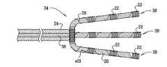
次に図4を参照する。図4は、本発明の代替実施形態によるカテーテル34の遠位部分を示す。カテーテル10(図1)と同様に、カテーテル34は、バックボーン36を有し、バックボーンは複数の分岐部38に分かれ、分岐部38はそれぞれ、図1の単一分岐の実施形態に関して前述したのと同じ構造を有している。適切な電極(図示せず)がカテーテル34に組み込まれる場合、複数の分岐部上にコイル22の大きなアレイを設けることは、高解像度の場所情報を備えた接触マッピングが迅速に達成されることを可能にする。例えば、分岐部38上のコイル22を使用した心内膜表面のマッピングは、目的の領域の迅速な識別を可能にし、電気的活性化が最も早い部位が正確に決定されうる。分岐部38は、可撓性で柔らかくなるように構築され、したがって、標的組織との非外傷性接触を確実にする。[Alternative Embodiment 2]
Reference is now made to FIG. FIG. 4 shows the distal portion of the
〔代替実施形態3〕
次に図5を参照する。図5は、本発明の代替実施形態によるカテーテル40の遠位部分を示す。カテーテル40の遠位部分は、第1の実施形態のように、複数のコイル22を備えている。しかしながら、バックボーンの代わりに、コイル22は、ねじれたワイヤ対42によって支持されている。このワイヤ対42は、コイル22を支持するのに十分丈夫であるが、可撓性である。カテーテル10(図1)と同様に、カテーテル40は、屈曲応答性である。カテーテル40の近位セグメント44とコイル22を接続するワイヤ対42は、ニッケルチタンなどの形状記憶合金で構築されうる。代わりに、コバルトクロム、および焼きなまされたステンレス鋼など、他の材料が使用されてよい。[Alternative Embodiment 3]
Reference is now made to FIG. FIG. 5 shows the distal portion of the
〔代替実施形態4〕
次に図6を参照する。図6は、本発明の代替実施形態によるカテーテル46の遠位部分を示す。カテーテル46の遠位部分は、複数の分岐部48に分かれ、分岐部48それぞれは、単一分岐カテーテル40(図5)と同じように構築される。[Alternative Embodiment 4]
Reference is now made to FIG. FIG. 6 shows the distal portion of the
本発明は、前記に詳細に示し説明したことに限定されるものではないことを、当業者は理解するであろう。むしろ、本発明の範囲は、本明細書で前述した様々な特徴のコンビネーションおよびサブコンビネーションの双方を含み、また、前記の説明を読めば当業者が想到するであろう、先行技術にはない、その変形および変更も含む。
〔実施の態様〕
(1) 侵襲的な医療用プローブ装置において、
被験者の身体に挿入するための遠位端部を有する、細長い可撓性プローブと、
複数のコイルであって、前記コイルは、前記プローブ上の基準場所に対して既知の関係で、種々のそれぞれの点で固定されており、外部で印加された磁場にさらされると、前記コイルは、そのコイルの位置座標に応答してそれぞれの信号を発生させる、複数のコイルと、
前記プローブの一部に沿った前記点のそれぞれの場所を決定するために、前記信号を受信し処理する、信号処理回路網と、
を含む、装置。
(2) 実施態様1に記載の装置において、
前記プローブは、近位セグメントを有し、
前記コイルは、前記コイルを前記近位セグメントに取り付ける可撓性接続ワイヤによって支持される、装置。
(3) 実施態様1に記載の装置において、
前記プローブは、複数の可撓性分岐部に分かれる遠位セグメントを有し、前記コイルは、前記分岐部上に分配される、装置。
(4) 実施態様1に記載の装置において、
前記コイルは、8〜70μmの範囲の直径を有するワイヤで形成される、装置。
(5) 実施態様1に記載の装置において、
前記コイルは、直径が15μmを超えないワイヤで形成される、装置。
(6) 実施態様1に記載の装置において、
前記コイルは、直径が10μmを超えないワイヤで形成される、装置。
(7) 実施態様1に記載の装置において、
前記プローブの直径が、8フレンチ(2.7mm)を超えない、装置。
(8) 実施態様1に記載の装置において、
内部の長さ方向バックボーン、
をさらに含み、
前記コイルは、前記バックボーン上で支えられる、装置。
(9) 実施態様8に記載の装置において、
前記コイルは、前記バックボーンに沿って延びるそれぞれのワイヤによって前記信号処理回路網に接続される、装置。
(10) 実施態様8に記載の装置において、
前記バックボーンは、長さ方向に孔のない材料で形成される、装置。
(11) 実施態様8に記載の装置において、
前記バックボーンは、強磁性材料を含む、装置。
(12) 実施態様8に記載の装置において、
前記バックボーンは、中央内腔を有する、装置。
(13) 実施態様1に記載の装置において、
前記信号処理回路網は、6次元で前記コイルの並進座標および向き座標を決定するように作用する、装置。
(14) 実施態様13に記載の装置において、
電極が、前記コイルのうち少なくとも1つに対して固定された場所で前記プローブ上に配され、前記信号処理回路網は、前記コイルの前記座標を決定することに応答して前記電極の座標を導き出すように作用する、装置。
(15) 実施態様1に記載の装置において、
前記信号処理回路網は、前記プローブの曲げ角度を決定するように作用する、装置。
(16) 実施態様1に記載の装置において、
前記信号処理回路網は、前記プローブの遠位部分の曲率半径を決定するように作用する、装置。
(17) 生きている被験者の体内における侵襲的なプローブを監視する方法において、
可撓性の細長いプローブの遠位端部を被験者に導入し、また複数のコイルを導入するステップであって、前記コイルは、前記遠位端部に対して既知の関係で、種々のそれぞれの点で固定されている、ステップと、
前記コイルが前記コイルの位置座標に応答してそれぞれの信号を発生させるように、外部で印加された磁場に前記コイルをさらすステップと、
前記プローブの一部の長さに沿った前記点のそれぞれの場所を決定するために前記信号を分析するステップと、
を含む、方法。
(18) 実施態様17に記載の方法において、
前記コイルは、直径が15μmを超えないワイヤで形成される、方法。
(19) 実施態様17に記載の方法において、
前記プローブの直径が、8フレンチ(2.7mm)を超えない、方法。
(20) 実施態様17に記載の方法において、
前記プローブは、内部の長さ方向バックボーンを有し、前記コイルは、前記バックボーン上で支えられる、方法。
(21) 実施態様17に記載の方法において、
前記信号を分析するステップは、6次元で前記コイルの並進座標および向き座標を決定するステップを含む、方法。
(22) 実施態様21に記載の方法において、
電極が、前記コイルのうち少なくとも1つに対して固定された場所で前記プローブ上に配され、
前記方法は、
前記コイルの前記座標を決定するステップに応答して前記電極の座標を導き出すステップ、
をさらに含む、方法。
(23) 実施態様17に記載の方法において、
前記信号を分析するステップは、前記プローブの曲げ角度を決定するステップを含む、方法。
(24) 実施態様17に記載の方法において、
前記プローブは、近位セグメントを有し、
前記方法は、
前記コイルを支持するため、可撓性接続ワイヤを前記コイルに取り付けて、前記ワイヤを前記近位セグメントに取り付けるステップ、
をさらに含む、方法。
(25) 実施態様17に記載の方法において、
前記プローブは、複数の可撓性分岐部に分かれる遠位セグメントを有し、前記コイルは、前記分岐部上に分配される、方法。
(26) 実施態様17に記載の方法において、
前記信号を分析するステップは、前記プローブの遠位部分の曲率半径を決定するステップを含む、方法。
(27) 侵襲的な医療用プローブを作る方法において、
細長い可撓性プローブに内部の長さ方向バックボーンを設けるステップであって、前記プローブは遠位端部を有する、ステップと、
複数のコイルを前記バックボーンの周りに配するステップであって、前記コイルは、前記遠位端部に対して既知の関係で、種々のそれぞれの点で固定されており、外部で印加される磁場にさらされると、前記コイルは、それぞれの信号を発生させる、ステップと、
前記コイルを信号処理回路網に接続するため、それぞれの接続ワイヤを前記コイルに取り付けるステップと、
前記接続ワイヤおよび前記バックボーンの周りに外層を貼り付けるステップと、
を含む、方法。
(28) 実施態様27に記載の方法において、
複数のコイルを配するステップは、前記バックボーンに前記コイルを巻き付けるステップを含む、方法。
(29) 実施態様27に記載の方法において、
複数のコイルを配するステップは、前記コイルを予め形成して、予め形成された前記コイルを前記バックボーンの上に滑らせるステップを含む、方法。
(30) 実施態様27に記載の方法において、
前記バックボーンを複数の分岐部に分けるステップと、
前記コイルを前記分岐部上に分配するステップと、
をさらに含む、方法。
(31) 侵襲的な医療用プローブを作る方法において、
前記プローブ上の基準点、近位セグメント、および遠位セグメントを定めるステップと、
前記基準点に対して既知の関係で、種々のそれぞれの点において、前記遠位セグメント上に複数のコイルを配するステップと、
支持する導電性ワイヤと、前記コイルおよび前記近位セグメントを相互接続するステップであって、前記導電性ワイヤは、信号処理回路網に接続可能である、ステップと、
を含む、方法。
(32) 実施態様31に記載の方法において、
複数のコイルを配するステップは、前記遠位セグメント上の分割点から生じる複数の分岐部において前記コイルを配列するステップを含む、方法。
Those skilled in the art will appreciate that the present invention is not limited to what has been particularly shown and described hereinabove. Rather, the scope of the present invention includes both combinations and subcombinations of the various features previously described herein, and is not in the prior art that would occur to those skilled in the art upon reading the foregoing description. The deformation | transformation and change are also included.
Embodiment
(1) In an invasive medical probe device,
An elongated flexible probe having a distal end for insertion into a subject's body;
A plurality of coils, said coils being fixed at various respective points in a known relationship to a reference location on said probe, said coil being exposed to an externally applied magnetic field; A plurality of coils for generating respective signals in response to the position coordinates of the coils;
Signal processing circuitry for receiving and processing the signal to determine the location of each of the points along a portion of the probe;
Including the device.
(2) In the apparatus according to Embodiment 1,
The probe has a proximal segment;
The apparatus wherein the coil is supported by a flexible connecting wire that attaches the coil to the proximal segment.
(3) In the apparatus according to Embodiment 1,
The apparatus, wherein the probe has a distal segment that divides into a plurality of flexible branches, and the coil is distributed on the branches.
(4) In the apparatus according to Embodiment 1,
The device, wherein the coil is formed of a wire having a diameter in the range of 8-70 μm.
(5) In the apparatus according to Embodiment 1,
The coil is formed of a wire whose diameter does not exceed 15 μm.
(6) In the apparatus according to Embodiment 1,
The coil is formed of a wire having a diameter not exceeding 10 μm.
(7) In the apparatus according to Embodiment 1,
Apparatus wherein the probe diameter does not exceed 8 French (2.7 mm).
(8) In the apparatus according to Embodiment 1,
Internal longitudinal backbone,
Further including
The apparatus, wherein the coil is supported on the backbone.
(9) In the apparatus according to embodiment 8,
The apparatus wherein the coil is connected to the signal processing circuitry by respective wires extending along the backbone.
(10) In the apparatus according to embodiment 8,
The device, wherein the backbone is formed of a material without holes in the length direction.
(11) In the apparatus according to embodiment 8,
The apparatus, wherein the backbone comprises a ferromagnetic material.
(12) In the apparatus according to embodiment 8,
The apparatus, wherein the backbone has a central lumen.
(13) In the apparatus according to Embodiment 1,
The signal processing circuitry is operative to determine the translational and orientation coordinates of the coil in six dimensions.
(14) In the apparatus according to embodiment 13,
An electrode is disposed on the probe at a fixed location relative to at least one of the coils, and the signal processing circuitry is configured to determine the coordinates of the electrode in response to determining the coordinates of the coil. A device that acts to derive.
(15) In the apparatus according to Embodiment 1,
The apparatus, wherein the signal processing circuitry is operative to determine a bending angle of the probe.
(16) In the apparatus according to Embodiment 1,
The apparatus, wherein the signal processing circuitry is operative to determine a radius of curvature of a distal portion of the probe.
(17) In a method of monitoring an invasive probe in the body of a living subject,
Introducing a distal end of a flexible elongate probe into a subject and introducing a plurality of coils, wherein the coils are in a known relationship with respect to the distal end in various respective manners. A step, fixed at a point,
Subjecting the coil to an externally applied magnetic field such that the coil generates respective signals in response to the position coordinates of the coil;
Analyzing the signal to determine the location of each of the points along the length of a portion of the probe;
Including a method.
(18) In the method of embodiment 17,
The method wherein the coil is formed of a wire having a diameter not exceeding 15 μm.
(19) In the method according to embodiment 17,
The method wherein the diameter of the probe does not exceed 8 French (2.7 mm).
(20) In the method of embodiment 17,
The method wherein the probe has an internal longitudinal backbone and the coil is supported on the backbone.
(21) In the method of embodiment 17,
Analyzing the signal comprises determining translational and orientation coordinates of the coil in six dimensions.
(22) In the method of embodiment 21,
An electrode is disposed on the probe at a fixed location relative to at least one of the coils;
The method
Deriving the coordinates of the electrode in response to determining the coordinates of the coil;
Further comprising a method.
(23) In the method of embodiment 17,
The method of analyzing the signal includes determining a bending angle of the probe.
(24) In the method of embodiment 17,
The probe has a proximal segment;
The method
Attaching a flexible connecting wire to the coil and supporting the wire to the proximal segment to support the coil;
Further comprising a method.
(25) In the method of embodiment 17,
The probe has a distal segment that divides into a plurality of flexible branches, and the coil is distributed on the branches.
(26) In the method of embodiment 17,
Analyzing the signal comprises determining a radius of curvature of a distal portion of the probe.
(27) In a method of making an invasive medical probe,
Providing an elongate flexible probe with an internal longitudinal backbone, the probe having a distal end;
Placing a plurality of coils around the backbone, the coils being fixed at various respective points in a known relationship to the distal end, and an externally applied magnetic field The coil generates a respective signal, and
Attaching each connection wire to the coil to connect the coil to a signal processing network;
Affixing an outer layer around the connecting wire and the backbone;
Including a method.
(28) In the method of embodiment 27,
Disposing a plurality of coils includes winding the coils around the backbone.
(29) In the method of embodiment 27,
Disposing a plurality of coils includes pre-forming the coil and sliding the pre-formed coil over the backbone.
(30) In the method of embodiment 27,
Dividing the backbone into a plurality of branches;
Distributing the coil on the branch;
Further comprising a method.
(31) In a method of making an invasive medical probe,
Defining a reference point, a proximal segment, and a distal segment on the probe;
Placing a plurality of coils on the distal segment at various respective points in a known relationship to the reference point;
Interconnecting a supporting conductive wire and the coil and the proximal segment, the conductive wire being connectable to a signal processing network;
Including a method.
(32) In the method of embodiment 31,
Arranging a plurality of coils includes arranging the coils at a plurality of branches resulting from split points on the distal segment.
Claims (12)
Translated fromJapanese被験者の身体に挿入するための遠位端部を有する、細長い可撓性プローブと、
複数のコイルであって、前記コイルは、前記プローブ上の基準場所に対して既知の関係で、種々のそれぞれの点で固定されており、外部で印加された磁場にさらされると、前記コイルは、そのコイルの位置座標に応答してそれぞれの信号を発生させる、複数のコイルと、
前記プローブの一部に沿った前記点のそれぞれの場所を決定するために、前記信号を受信し処理する、信号処理回路網と、
を含み、
前記プローブは、近位セグメントを有し、
前記複数のコイルの内の1のコイルは、該1のコイルを前記近位セグメントに取り付ける第1の可撓性接続ワイヤによって支持され、前記複数のコイルの内で前記1のコイルの遠位側に位置する他のコイルは、該他のコイルを前記1のコイルに取り付ける第2の可撓性接続ワイヤによって支持される、装置。In an invasive medical probe device,
An elongated flexible probe having a distal end for insertion into a subject's body;
A plurality of coils, said coils being fixed at various respective points in a known relationship to a reference location on said probe, said coil being exposed to an externally applied magnetic field; A plurality of coils for generating respective signals in response to the position coordinates of the coils;
Signal processing circuitry for receiving and processing the signal to determine the location of each of the points along a portion of the probe;
Only including,
The probe has a proximal segment;
One coil of the plurality of coils is supported by a first flexible connecting wire that attaches the one coil to the proximal segment and is distal of the one coil within the plurality of coils. The other coil located at is supported by a second flexible connecting wire that attaches the other coil to the first coil .
前記プローブは、複数の可撓性分岐部に分かれる遠位セグメントを有し、前記コイルは、前記分岐部上に分配される、装置。The apparatus of claim 1.
The apparatus, wherein the probe has a distal segment that divides into a plurality of flexible branches, and the coil is distributed on the branches.
前記コイルは、8〜70μmの範囲の直径を有するワイヤで形成される、装置。The apparatus of claim 1.
The device, wherein the coil is formed of a wire having a diameter in the range of 8-70 μm.
前記コイルは、直径が15μmを超えないワイヤで形成される、装置。The apparatus of claim 1.
The coil is formed of a wire whose diameter does not exceed 15 μm.
前記コイルは、直径が10μmを超えないワイヤで形成される、装置。The apparatus of claim 1.
The coil is formed of a wire having a diameter not exceeding 10 μm.
前記プローブの直径が、8フレンチ(2.7mm)を超えない、装置。The apparatus of claim 1.
Apparatus wherein the probe diameter does not exceed 8 French (2.7 mm).
前記信号処理回路網は、6次元で前記コイルの並進座標および向き座標を決定するように作用する、装置。The apparatus of claim 1.
The signal processing circuitry is operative to determine the translational and orientation coordinates of the coil in six dimensions.
電極が、前記コイルのうち少なくとも1つに対して固定された場所で前記プローブ上に配され、前記信号処理回路網は、前記コイルの前記座標を決定することに応答して前記電極の座標を導き出すように作用する、装置。The apparatus of claim7 .
An electrode is disposed on the probe at a fixed location relative to at least one of the coils, and the signal processing circuitry is configured to determine the coordinates of the electrode in response to determining the coordinates of the coil. A device that acts to derive.
前記信号処理回路網は、前記プローブの曲げ角度を決定するように作用する、装置。The apparatus of claim 1.
The apparatus, wherein the signal processing circuitry is operative to determine a bending angle of the probe.
前記信号処理回路網は、前記プローブの遠位部分の曲率半径を決定するように作用する、装置。The apparatus of claim 1.
The apparatus, wherein the signal processing circuitry is operative to determine a radius of curvature of a distal portion of the probe.
前記プローブ上の基準点、近位セグメント、および遠位セグメントを定めるステップと、
前記基準点に対して既知の関係で、種々のそれぞれの点において、複数のコイルを配するステップと、
前記複数のコイルの内の1のコイルを支持する第1の導電性ワイヤと、前記1のコイルおよび前記近位セグメントを相互接続すると共に、前記複数のコイルの内で前記1のコイルの遠位側に位置する他のコイルを支持する第2の導電性ワイヤと、前記1のコイルおよび前記他のコイルを相互接続するステップであって、前記第1の導電性ワイヤは、信号処理回路網に接続可能である、ステップと、
を含む、方法。In a method of making an invasive medical probe,
Defining a reference point, a proximal segment, and a distal segment on the probe;
Placing aplurality of coils at various respective points in a known relationship to the reference point;
Afirst conductive wire for supportingthe primary coil of the plurality of coils, saidwith the coil and the proximal segmentof oneinterconnecting distal of said first coil of said plurality of coils Interconnecting the first coil and the other coil with a second conductive wire supporting another coil located on the side , whereinthe first conductive wire is connected to the signal processing network Connectable, step, and
Including a method.
複数のコイルを配するステップは、前記遠位セグメント上の分割点から生じる複数の分岐部において前記コイルを配列するステップを含む、方法。The method of claim11 , wherein
Arranging a plurality of coils includes arranging the coils at a plurality of branches resulting from split points on the distal segment.
Applications Claiming Priority (2)
| Application Number | Priority Date | Filing Date | Title |
|---|---|---|---|
| US12/186,631 | 2008-08-06 | ||
| US12/186,631US8926528B2 (en) | 2008-08-06 | 2008-08-06 | Single-axis sensors on flexible backbone |
Publications (2)
| Publication Number | Publication Date |
|---|---|
| JP2010036040A JP2010036040A (en) | 2010-02-18 |
| JP5575431B2true JP5575431B2 (en) | 2014-08-20 |
Family
ID=41277490
Family Applications (1)
| Application Number | Title | Priority Date | Filing Date |
|---|---|---|---|
| JP2009182073AActiveJP5575431B2 (en) | 2008-08-06 | 2009-08-05 | Single axis sensor on flexible backbone |
Country Status (9)
| Country | Link |
|---|---|
| US (2) | US8926528B2 (en) |
| EP (3) | EP2151209B1 (en) |
| JP (1) | JP5575431B2 (en) |
| CN (1) | CN101675879B (en) |
| AU (1) | AU2009206166B2 (en) |
| CA (1) | CA2674225C (en) |
| ES (1) | ES2725801T3 (en) |
| IL (2) | IL199852A (en) |
| RU (1) | RU2009130116A (en) |
Families Citing this family (44)
| Publication number | Priority date | Publication date | Assignee | Title |
|---|---|---|---|---|
| US8855771B2 (en) | 2011-01-28 | 2014-10-07 | Cyberonics, Inc. | Screening devices and methods for obstructive sleep apnea therapy |
| US9186511B2 (en) | 2006-10-13 | 2015-11-17 | Cyberonics, Inc. | Obstructive sleep apnea treatment devices, systems and methods |
| US9205262B2 (en) | 2011-05-12 | 2015-12-08 | Cyberonics, Inc. | Devices and methods for sleep apnea treatment |
| CA2666529A1 (en) | 2006-10-13 | 2008-04-24 | Apnex Medical, Inc. | Obstructive sleep apnea treatment devices, systems and methods |
| US9744354B2 (en) | 2008-12-31 | 2017-08-29 | Cyberonics, Inc. | Obstructive sleep apnea treatment devices, systems and methods |
| US9913982B2 (en) | 2011-01-28 | 2018-03-13 | Cyberonics, Inc. | Obstructive sleep apnea treatment devices, systems and methods |
| US8437832B2 (en) | 2008-06-06 | 2013-05-07 | Biosense Webster, Inc. | Catheter with bendable tip |
| EP2331201B1 (en) | 2008-10-01 | 2020-04-29 | Inspire Medical Systems, Inc. | System for treating sleep apnea transvenously |
| JP5575789B2 (en) | 2008-11-19 | 2014-08-20 | インスパイア・メディカル・システムズ・インコーポレイテッド | How to treat sleep-disordered breathing |
| US9326700B2 (en) | 2008-12-23 | 2016-05-03 | Biosense Webster (Israel) Ltd. | Catheter display showing tip angle and pressure |
| JP2012521864A (en) | 2009-03-31 | 2012-09-20 | インスパイア・メディカル・システムズ・インコーポレイテッド | Percutaneous access method in a system for treating sleep-related abnormal breathing |
| US10688278B2 (en) | 2009-11-30 | 2020-06-23 | Biosense Webster (Israel), Ltd. | Catheter with pressure measuring tip |
| US9888864B2 (en) | 2010-03-12 | 2018-02-13 | Inspire Medical Systems, Inc. | Method and system for identifying a location for nerve stimulation |
| US8226580B2 (en) | 2010-06-30 | 2012-07-24 | Biosense Webster (Israel), Ltd. | Pressure sensing for a multi-arm catheter |
| US8617087B2 (en) | 2010-12-03 | 2013-12-31 | Biosense Webster, Inc. | Control handle with rotational cam mechanism for contraction/deflection of medical device |
| US8792962B2 (en) | 2010-12-30 | 2014-07-29 | Biosense Webster, Inc. | Catheter with single axial sensors |
| US9687289B2 (en) | 2012-01-04 | 2017-06-27 | Biosense Webster (Israel) Ltd. | Contact assessment based on phase measurement |
| ES3015082T3 (en)* | 2012-05-19 | 2025-04-29 | Taris Biomedical Llc | Implantable urological device with retrieval feature |
| JP2016531271A (en) | 2013-03-14 | 2016-10-06 | カリフォルニア インスティチュート オブ テクノロジー | Anomaly detection of electrical and electrochemical energy units |
| EP3019088B1 (en) | 2013-07-08 | 2020-12-02 | Koninklijke Philips N.V. | Imaging apparatus for biopsy or brachytherapy |
| DE102013214067A1 (en) | 2013-07-17 | 2015-01-22 | Fiagon Gmbh | Device and method for connecting a medical instrument to a position detection system |
| DE102013222230A1 (en) | 2013-10-31 | 2015-04-30 | Fiagon Gmbh | Surgical instrument |
| US10105073B2 (en)* | 2013-11-21 | 2018-10-23 | Biosense Webster (Israel) Ltd | Flexible multiple-arm diagnostic catheter |
| US9480416B2 (en)* | 2014-01-17 | 2016-11-01 | Biosense Webster (Israel) Ltd. | Signal transmission using catheter braid wires |
| EP3104768B1 (en) | 2014-02-11 | 2023-07-26 | Cyberonics, Inc. | Systems for detecting and treating obstructive sleep apnea |
| US9750422B2 (en)* | 2014-02-12 | 2017-09-05 | Biosense Webster (Israel) Ltd | Catheter with transverse branches |
| US9986949B2 (en)* | 2014-03-05 | 2018-06-05 | Biosense Webster (Israel) Ltd. | Multi-arm catheter with signal transmission over braid wires |
| EP3206576B1 (en) | 2014-10-15 | 2019-09-04 | St. Jude Medical, Cardiology Division, Inc. | Methods and systems for mapping local conduction velocity |
| US9839766B2 (en) | 2014-10-20 | 2017-12-12 | Medtronic Cryocath Lp | Centering coiled guide |
| WO2016100919A1 (en) | 2014-12-19 | 2016-06-23 | California Institute Of Technology | Improved systems and methods for management and monitoring of energy storage and distribution |
| US11478304B2 (en) | 2015-03-31 | 2022-10-25 | Medtronic Navigation, Inc. | Flexible circuit coils |
| WO2017004271A1 (en)* | 2015-06-30 | 2017-01-05 | Boston Scientific Scimed Inc. | Robust miniature magnetic sensor |
| EP4083640B1 (en) | 2015-10-01 | 2025-06-04 | California Institute of Technology | Systems and methods for monitoring characteristics of energy units |
| US10849521B2 (en) | 2015-12-23 | 2020-12-01 | Biosense Webster (Israel) Ltd. | Multi-layered catheter shaft construction with embedded single axial sensors, and related methods |
| US20180228393A1 (en)* | 2017-02-15 | 2018-08-16 | Biosense Webster (Israel) Ltd. | Electrophysiologic device construction |
| DE102017008148A1 (en)* | 2017-08-29 | 2019-02-28 | Joimax Gmbh | Sensor unit, intraoperative navigation system and method for detecting a surgical instrument |
| US20200178929A1 (en)* | 2018-12-07 | 2020-06-11 | Biosense Webster (Israel) Ltd. | Mapping endocardial sub-surface characteristics |
| EP3719749A1 (en) | 2019-04-03 | 2020-10-07 | Fiagon AG Medical Technologies | Registration method and setup |
| SG11202110918UA (en)* | 2019-05-02 | 2021-10-28 | Intersect Ent Int Gmbh | Sensor carrier |
| US11759150B2 (en)* | 2019-08-27 | 2023-09-19 | Biosense Webster (Israel) Ltd. | Accurate basket catheter tracking |
| CN110786931B (en)* | 2019-12-03 | 2023-02-28 | 昆山雷盛医疗科技有限公司 | Device and method for enhancing display of ultrasonic image |
| US12097339B2 (en) | 2019-12-31 | 2024-09-24 | Biosense Webster (Israel) Ltd. | System and methods of using a catheter with an anchoring mechanism |
| US11730551B2 (en) | 2020-02-24 | 2023-08-22 | Canon U.S.A., Inc. | Steerable medical device with strain relief elements |
| US12396657B2 (en) | 2021-04-29 | 2025-08-26 | Biosense Webster (Israel) Ltd. | Non-linear single axis navigation sensor with strain relief |
Family Cites Families (26)
| Publication number | Priority date | Publication date | Assignee | Title |
|---|---|---|---|---|
| CA91765A (en) | 1905-01-23 | 1905-02-28 | Dilbert Perry Springer | Rail joint |
| AU675077B2 (en) | 1992-08-14 | 1997-01-23 | British Telecommunications Public Limited Company | Position location system |
| IL116699A (en) | 1996-01-08 | 2001-09-13 | Biosense Ltd | Method of constructing cardiac map |
| AU1693095A (en) | 1994-08-19 | 1996-03-14 | Biosense, Inc. | Medical diagnosis, treatment and imaging systems |
| US6690963B2 (en)* | 1995-01-24 | 2004-02-10 | Biosense, Inc. | System for determining the location and orientation of an invasive medical instrument |
| AU706052B2 (en) | 1996-02-15 | 1999-06-10 | Biosense, Inc. | Movable transmit or receive coils for location system |
| SI0901341T1 (en)* | 1997-01-03 | 2005-04-30 | Biosense Webster, Inc. | Bend-responsive catheter |
| IL126016A (en) | 1997-01-03 | 2003-06-24 | Biosense Inc | Conformal catheter |
| WO2000010456A1 (en)* | 1998-08-02 | 2000-03-02 | Super Dimension Ltd. | Intrabody navigation system for medical applications |
| US6233476B1 (en)* | 1999-05-18 | 2001-05-15 | Mediguide Ltd. | Medical positioning system |
| US20030018251A1 (en) | 2001-04-06 | 2003-01-23 | Stephen Solomon | Cardiological mapping and navigation system |
| US6961602B2 (en)* | 2001-12-31 | 2005-11-01 | Biosense Webster, Inc. | Catheter having multiple spines each having electrical mapping and location sensing capabilities |
| US6883081B2 (en)* | 2002-07-30 | 2005-04-19 | Veritas Operating Corporation | Storage management software bridges |
| US7130700B2 (en)* | 2002-11-19 | 2006-10-31 | Medtronic, Inc. | Multilumen body for an implantable medical device |
| US7697972B2 (en) | 2002-11-19 | 2010-04-13 | Medtronic Navigation, Inc. | Navigation system for cardiac therapies |
| US7003342B2 (en)* | 2003-06-02 | 2006-02-21 | Biosense Webster, Inc. | Catheter and method for mapping a pulmonary vein |
| WO2005067563A2 (en)* | 2004-01-12 | 2005-07-28 | Calypso Medical Technologies, Inc. | Instruments with location markers and methods for tracking instruments through anatomical passageways |
| JP3981364B2 (en)* | 2004-03-19 | 2007-09-26 | オリンパス株式会社 | Double balloon endoscope system |
| WO2005112836A2 (en)* | 2004-05-18 | 2005-12-01 | Johns Hopkins University | Interventional devices for chronic total occlusion recanalization under mri guidance |
| JP4708963B2 (en)* | 2005-11-09 | 2011-06-22 | Hoya株式会社 | Endoscope insertion part shape grasping system |
| JP2009532127A (en)* | 2006-03-31 | 2009-09-10 | メドトロニック ヴァスキュラー インコーポレイテッド | Nested catheter with electromagnetic coil for imaging and navigation during cardiac procedures |
| WO2008028149A2 (en) | 2006-09-01 | 2008-03-06 | Voyage Medical, Inc. | Electrophysiology mapping and visualization system |
| US20080139915A1 (en)* | 2006-12-07 | 2008-06-12 | Medtronic Vascular, Inc. | Vascular Position Locating and/or Mapping Apparatus and Methods |
| US8473030B2 (en)* | 2007-01-12 | 2013-06-25 | Medtronic Vascular, Inc. | Vessel position and configuration imaging apparatus and methods |
| EP2198317A2 (en)* | 2007-09-24 | 2010-06-23 | Boston Scientific Limited | Mri phase visualization of interventional devices |
| US20090306651A1 (en)* | 2008-06-09 | 2009-12-10 | Clint Schneider | Catheter assembly with front-loaded tip |
- 2008
- 2008-08-06USUS12/186,631patent/US8926528B2/enactiveActive
- 2009
- 2009-07-14ILIL199852Apatent/IL199852A/enactiveIP Right Grant
- 2009-07-31CACA2674225Apatent/CA2674225C/enactiveActive
- 2009-08-05EPEP09251939.6Apatent/EP2151209B1/enactiveActive
- 2009-08-05AUAU2009206166Apatent/AU2009206166B2/ennot_activeCeased
- 2009-08-05EPEP11178609.1Apatent/EP2389890A3/ennot_activeCeased
- 2009-08-05JPJP2009182073Apatent/JP5575431B2/enactiveActive
- 2009-08-05ESES09251939Tpatent/ES2725801T3/enactiveActive
- 2009-08-05EPEP14160474.4Apatent/EP2749243A3/ennot_activeWithdrawn
- 2009-08-05RURU2009130116/14Apatent/RU2009130116A/ennot_activeApplication Discontinuation
- 2009-08-06CNCN200910165862.9Apatent/CN101675879B/enactiveActive
- 2014
- 2014-05-23USUS14/285,667patent/US10416247B2/enactiveActive
- 2015
- 2015-04-30ILIL238561Apatent/IL238561B/enactiveIP Right Grant
Also Published As
| Publication number | Publication date |
|---|---|
| CN101675879B (en) | 2015-04-29 |
| US8926528B2 (en) | 2015-01-06 |
| EP2151209B1 (en) | 2019-02-27 |
| RU2009130116A (en) | 2011-02-10 |
| IL199852A0 (en) | 2010-04-29 |
| JP2010036040A (en) | 2010-02-18 |
| EP2389890A3 (en) | 2013-12-04 |
| CA2674225C (en) | 2018-10-02 |
| EP2389890A2 (en) | 2011-11-30 |
| IL238561B (en) | 2020-08-31 |
| ES2725801T3 (en) | 2019-09-27 |
| CA2674225A1 (en) | 2010-02-06 |
| AU2009206166B2 (en) | 2015-03-05 |
| US20100036285A1 (en) | 2010-02-11 |
| EP2151209A3 (en) | 2011-01-19 |
| IL238561A0 (en) | 2015-06-30 |
| EP2749243A3 (en) | 2017-06-14 |
| CN101675879A (en) | 2010-03-24 |
| US10416247B2 (en) | 2019-09-17 |
| US20140317910A1 (en) | 2014-10-30 |
| AU2009206166A1 (en) | 2010-02-25 |
| IL199852A (en) | 2015-06-30 |
| EP2151209A2 (en) | 2010-02-10 |
| EP2749243A2 (en) | 2014-07-02 |
Similar Documents
| Publication | Publication Date | Title |
|---|---|---|
| JP5575431B2 (en) | Single axis sensor on flexible backbone | |
| JP7622162B2 (en) | Automatic display of the earliest LAT | |
| CN112971806B (en) | Multidimensional acquisition of bipolar signals from catheters | |
| US11109788B2 (en) | Catheter with Fibonacci distributed electrodes | |
| US10463267B2 (en) | Device and method for the geometric determination of electrical dipole densities on the cardiac wall | |
| AU2015234342B2 (en) | Dual-purpose lasso catheter with irrigation field of the invention | |
| AU2004203441B2 (en) | Lasso for pulmonary vein mapping and ablation | |
| JP3949729B2 (en) | Shape adaptive catheter | |
| JP4027976B2 (en) | Mapping catheter | |
| JP5031285B2 (en) | Hybrid magnetic and impedance based position detection system | |
| JP2016144642A (en) | Basket catheter with far-field electrode | |
| CN120093409A (en) | Monitors torsion on distal tip assembly |
Legal Events
| Date | Code | Title | Description |
|---|---|---|---|
| RD04 | Notification of resignation of power of attorney | Free format text:JAPANESE INTERMEDIATE CODE: A7424 Effective date:20100805 | |
| RD04 | Notification of resignation of power of attorney | Free format text:JAPANESE INTERMEDIATE CODE: A7424 Effective date:20111208 | |
| A621 | Written request for application examination | Free format text:JAPANESE INTERMEDIATE CODE: A621 Effective date:20120612 | |
| A977 | Report on retrieval | Free format text:JAPANESE INTERMEDIATE CODE: A971007 Effective date:20131018 | |
| A601 | Written request for extension of time | Free format text:JAPANESE INTERMEDIATE CODE: A601 Effective date:20140205 | |
| A602 | Written permission of extension of time | Free format text:JAPANESE INTERMEDIATE CODE: A602 Effective date:20140210 | |
| A521 | Request for written amendment filed | Free format text:JAPANESE INTERMEDIATE CODE: A523 Effective date:20140304 | |
| TRDD | Decision of grant or rejection written | ||
| A01 | Written decision to grant a patent or to grant a registration (utility model) | Free format text:JAPANESE INTERMEDIATE CODE: A01 Effective date:20140603 | |
| A61 | First payment of annual fees (during grant procedure) | Free format text:JAPANESE INTERMEDIATE CODE: A61 Effective date:20140702 | |
| R150 | Certificate of patent or registration of utility model | Ref document number:5575431 Country of ref document:JP Free format text:JAPANESE INTERMEDIATE CODE: R150 | |
| R250 | Receipt of annual fees | Free format text:JAPANESE INTERMEDIATE CODE: R250 | |
| R250 | Receipt of annual fees | Free format text:JAPANESE INTERMEDIATE CODE: R250 | |
| R250 | Receipt of annual fees | Free format text:JAPANESE INTERMEDIATE CODE: R250 | |
| R250 | Receipt of annual fees | Free format text:JAPANESE INTERMEDIATE CODE: R250 | |
| R250 | Receipt of annual fees | Free format text:JAPANESE INTERMEDIATE CODE: R250 | |
| R250 | Receipt of annual fees | Free format text:JAPANESE INTERMEDIATE CODE: R250 | |
| R250 | Receipt of annual fees | Free format text:JAPANESE INTERMEDIATE CODE: R250 | |
| R250 | Receipt of annual fees | Free format text:JAPANESE INTERMEDIATE CODE: R250 | |
| R250 | Receipt of annual fees | Free format text:JAPANESE INTERMEDIATE CODE: R250 |