JP5574298B2 - Wave actuated pump and means for connecting it to the seabed - Google Patents
Wave actuated pump and means for connecting it to the seabedDownload PDFInfo
- Publication number
- JP5574298B2 JP5574298B2JP2011517231AJP2011517231AJP5574298B2JP 5574298 B2JP5574298 B2JP 5574298B2JP 2011517231 AJP2011517231 AJP 2011517231AJP 2011517231 AJP2011517231 AJP 2011517231AJP 5574298 B2JP5574298 B2JP 5574298B2
- Authority
- JP
- Japan
- Prior art keywords
- cylinder
- tube
- pump
- container
- rod
- Prior art date
- Legal status (The legal status is an assumption and is not a legal conclusion. Google has not performed a legal analysis and makes no representation as to the accuracy of the status listed.)
- Expired - Fee Related
Links
- 239000012530fluidSubstances0.000claimsdescription23
- XLYOFNOQVPJJNP-UHFFFAOYSA-NwaterSubstancesOXLYOFNOQVPJJNP-UHFFFAOYSA-N0.000claimsdescription13
- 238000007667floatingMethods0.000claimsdescription8
- 238000005086pumpingMethods0.000description18
- 238000000034methodMethods0.000description8
- 230000005611electricityEffects0.000description6
- 230000033001locomotionEffects0.000description6
- 239000000463materialSubstances0.000description6
- 230000000630rising effectEffects0.000description5
- 230000006378damageEffects0.000description4
- 239000013535sea waterSubstances0.000description3
- 238000001914filtrationMethods0.000description2
- 230000005484gravityEffects0.000description2
- 230000007774longtermEffects0.000description2
- 238000012423maintenanceMethods0.000description2
- 238000004519manufacturing processMethods0.000description2
- 239000003921oilSubstances0.000description2
- 239000003643water by typeSubstances0.000description2
- 230000003213activating effectEffects0.000description1
- 230000005540biological transmissionEffects0.000description1
- 238000010276constructionMethods0.000description1
- 230000007797corrosionEffects0.000description1
- 238000005260corrosionMethods0.000description1
- 230000008878couplingEffects0.000description1
- 238000010168coupling processMethods0.000description1
- 238000005859coupling reactionMethods0.000description1
- 230000007547defectEffects0.000description1
- 238000006073displacement reactionMethods0.000description1
- 239000002803fossil fuelSubstances0.000description1
- 229910001385heavy metalInorganic materials0.000description1
- 238000009434installationMethods0.000description1
- 230000005923long-lasting effectEffects0.000description1
- 238000007567mass-production techniqueMethods0.000description1
- 229910052751metalInorganic materials0.000description1
- 239000002184metalSubstances0.000description1
- 238000005381potential energyMethods0.000description1
- 230000004224protectionEffects0.000description1
- 238000011084recoveryMethods0.000description1
- 230000001105regulatory effectEffects0.000description1
- 239000002023woodSubstances0.000description1
Images


Classifications
- F—MECHANICAL ENGINEERING; LIGHTING; HEATING; WEAPONS; BLASTING
- F03—MACHINES OR ENGINES FOR LIQUIDS; WIND, SPRING, OR WEIGHT MOTORS; PRODUCING MECHANICAL POWER OR A REACTIVE PROPULSIVE THRUST, NOT OTHERWISE PROVIDED FOR
- F03B—MACHINES OR ENGINES FOR LIQUIDS
- F03B13/00—Adaptations of machines or engines for special use; Combinations of machines or engines with driving or driven apparatus; Power stations or aggregates
- F03B13/12—Adaptations of machines or engines for special use; Combinations of machines or engines with driving or driven apparatus; Power stations or aggregates characterised by using wave or tide energy
- F03B13/14—Adaptations of machines or engines for special use; Combinations of machines or engines with driving or driven apparatus; Power stations or aggregates characterised by using wave or tide energy using wave energy
- F03B13/16—Adaptations of machines or engines for special use; Combinations of machines or engines with driving or driven apparatus; Power stations or aggregates characterised by using wave or tide energy using wave energy using the relative movement between a wave-operated member, i.e. a "wom" and another member, i.e. a reaction member or "rem"
- F03B13/18—Adaptations of machines or engines for special use; Combinations of machines or engines with driving or driven apparatus; Power stations or aggregates characterised by using wave or tide energy using wave energy using the relative movement between a wave-operated member, i.e. a "wom" and another member, i.e. a reaction member or "rem" where the other member, i.e. rem is fixed, at least at one point, with respect to the sea bed or shore
- F03B13/1885—Adaptations of machines or engines for special use; Combinations of machines or engines with driving or driven apparatus; Power stations or aggregates characterised by using wave or tide energy using wave energy using the relative movement between a wave-operated member, i.e. a "wom" and another member, i.e. a reaction member or "rem" where the other member, i.e. rem is fixed, at least at one point, with respect to the sea bed or shore and the wom is tied to the rem
- F03B13/189—Adaptations of machines or engines for special use; Combinations of machines or engines with driving or driven apparatus; Power stations or aggregates characterised by using wave or tide energy using wave energy using the relative movement between a wave-operated member, i.e. a "wom" and another member, i.e. a reaction member or "rem" where the other member, i.e. rem is fixed, at least at one point, with respect to the sea bed or shore and the wom is tied to the rem acting directly on the piston of a pump
- F—MECHANICAL ENGINEERING; LIGHTING; HEATING; WEAPONS; BLASTING
- F04—POSITIVE - DISPLACEMENT MACHINES FOR LIQUIDS; PUMPS FOR LIQUIDS OR ELASTIC FLUIDS
- F04B—POSITIVE-DISPLACEMENT MACHINES FOR LIQUIDS; PUMPS
- F04B17/00—Pumps characterised by combination with, or adaptation to, specific driving engines or motors
- Y—GENERAL TAGGING OF NEW TECHNOLOGICAL DEVELOPMENTS; GENERAL TAGGING OF CROSS-SECTIONAL TECHNOLOGIES SPANNING OVER SEVERAL SECTIONS OF THE IPC; TECHNICAL SUBJECTS COVERED BY FORMER USPC CROSS-REFERENCE ART COLLECTIONS [XRACs] AND DIGESTS
- Y02—TECHNOLOGIES OR APPLICATIONS FOR MITIGATION OR ADAPTATION AGAINST CLIMATE CHANGE
- Y02A—TECHNOLOGIES FOR ADAPTATION TO CLIMATE CHANGE
- Y02A20/00—Water conservation; Efficient water supply; Efficient water use
- Y02A20/124—Water desalination
- Y02A20/138—Water desalination using renewable energy
- Y02A20/144—Wave energy
- Y—GENERAL TAGGING OF NEW TECHNOLOGICAL DEVELOPMENTS; GENERAL TAGGING OF CROSS-SECTIONAL TECHNOLOGIES SPANNING OVER SEVERAL SECTIONS OF THE IPC; TECHNICAL SUBJECTS COVERED BY FORMER USPC CROSS-REFERENCE ART COLLECTIONS [XRACs] AND DIGESTS
- Y02—TECHNOLOGIES OR APPLICATIONS FOR MITIGATION OR ADAPTATION AGAINST CLIMATE CHANGE
- Y02E—REDUCTION OF GREENHOUSE GAS [GHG] EMISSIONS, RELATED TO ENERGY GENERATION, TRANSMISSION OR DISTRIBUTION
- Y02E10/00—Energy generation through renewable energy sources
- Y02E10/30—Energy from the sea, e.g. using wave energy or salinity gradient
Landscapes
- Engineering & Computer Science (AREA)
- Mechanical Engineering (AREA)
- General Engineering & Computer Science (AREA)
- Chemical & Material Sciences (AREA)
- Combustion & Propulsion (AREA)
- Other Liquid Machine Or Engine Such As Wave Power Use (AREA)
- Compressors, Vaccum Pumps And Other Relevant Systems (AREA)
Description
Translated fromJapanese本発明は、海、海洋および湖などの水域における波の動きからエネルギーを生成するための方法および装置に関する。 The present invention relates to a method and apparatus for generating energy from wave motion in waters such as seas, oceans and lakes.
本発明の目的は、世界の海洋および湖から再生可能な波エネルギーの採取を可能にすることである。 The object of the present invention is to enable the collection of renewable wave energy from the world's oceans and lakes.
この目的を達成するために過去に多くのデバイスが提案されてきた。以下の1つまたは複数の理由が原因でほとんどのものが商業化されなかった。Many devices have been proposed in the past to achieve this goal. Most have not been commercialized due to one or more of the following reasons.
1/デバイスを製造するのに費用がかかりすぎ、それ故従来のエネルギー生成の化石燃料手段と競うことができない。1 / Devices are too expensive to manufacture and therefore cannot compete with conventional energy-generating fossil fuel means.
2/多くのデバイスが極めて複雑である。特に海洋環境ではばね、動索、滑車、軸受、ギアボックスおよび他の回転装置、電気または電子制御装置などの構成要素は全て耐用年数が制限されている。2 / Many devices are extremely complex. Particularly in marine environments, components such as springs, moving cords, pulleys, bearings, gearboxes and other rotating devices, electrical or electronic control devices are all limited in their useful lives.
3/多くのデバイスが海で電気を生成しその後それを陸上に送電することを試みる。水、特に海水と電気は水と油のように混ざらない。海水と電気を混合させようとする試みはいずれも建設コストが大きくなり、欠陥および腐食の問題によって長期間の使用は信頼性に欠けることになる。3 / Many devices try to generate electricity at sea and then transmit it to land. Water, especially seawater and electricity, does not mix like water and oil. Any attempt to mix seawater and electricity will increase construction costs, and long-term use will be unreliable due to defects and corrosion problems.
4/多くのデバイスは嵐や高波に耐えることができない。4 / Many devices cannot withstand storms and high waves.
5/多くのデバイスは、業界の基準である少なくとも20年の推定耐用年数を達成するのに不可欠な長期間の保守性およびメンテナンス要件を考慮していない。5 / Many devices do not take into account the long-term maintainability and maintenance requirements that are essential to achieving an industry standard estimated lifetime of at least 20 years.
6/多くのデバイスは、放出された場合ともすれば環境を損なう可能性のある油、重金属および他の材料の使用が不可欠である。6 / Many devices require the use of oils, heavy metals and other materials that, if released, can potentially harm the environment.
したがって、上記のいくつかのまたは全ての問題に対処する水域において波からエネルギーを生成するための改良されたシステムおよび方法に対する要望がある。 Accordingly, there is a need for improved systems and methods for generating energy from waves in waters that address some or all of the above problems.
海の波エネルギーを獲得するために従来技術が記述するデバイスは広範囲にわたる。しかしながらこの提案されるデバイスに密接に関連する従来技術はわずかな例に限定される。最も関係するのは以下のものである。The devices described by the prior art to capture ocean wave energy are extensive. However, the prior art closely related to this proposed device is limited to a few examples. The most relevant are:
WINDLEの欧州特許番号第0265594号は、往復動作の戻り行程を作動させるためにロープおよび滑車を備えたまたはそれらのないばねまたはおもりまたは浮きに頼る浮き作動式の往復ポンプを開示している。Windleはまた、往復ポンプの浮きおよび土台に対する設置の多様な構成も開示している。ポンプは逆さにされることもあり、あるいは浮きの中にまたは海底にまたは他の構成で設置される場合もある。WINDLE European Patent No. 0265594 discloses a float-actuated reciprocating pump that relies on a spring or weight or float with or without a rope and pulley to actuate a reciprocating return stroke. Windle also discloses various configurations of reciprocating pump float and foundation installations. The pump may be turned upside down or installed in the float or on the seabed or in other configurations.
またJANODYのフランス特許第2800423号は、往復動作の戻り行程を作動させるためのばねを開示している。Also, JANODY French Patent No. 2800423 discloses a spring for actuating the return stroke of a reciprocating motion.
BURNSのカナダ特許第2619100号は中空のピストンを利用するポンプを開示しているが、専ら往復動作の戻り行程を作動させるのに重力の使用を提案している。BURNS Canadian Patent 2,619,100 discloses a pump that utilizes a hollow piston, but proposes the use of gravity exclusively to actuate the reciprocating return stroke.
ONOの米国特許第4,398,095号は、表面の空気と深いところの水圧との圧力差を利用することによって往復動作の戻り行程を作動させる水圧式の方法を開示している。ONO U.S. Pat. No. 4,398,095 discloses a hydraulic method of operating the return stroke of a reciprocating operation by utilizing the pressure difference between surface air and deep water pressure.
WOODのイギリス特許第2428747号は、単一の水圧シリンダに係留された浮きを備えた波エネルギーシステムを開示している。WOOD British Patent No. 2,428,747 discloses a wave energy system with a float moored in a single hydraulic cylinder.
同様にHICKS等の米国特許第4,326,840号は、海底で水圧シリンダに係留された浮きを有する波駆動式ポンプを開示している。波が動力を与える汲み上げ装置および方法はWINDLEの米国特許第4,883,411号にも開示されている。Similarly, U.S. Pat. No. 4,326,840 to HICKS et al. Discloses a wave driven pump having a float moored to a hydraulic cylinder at the sea floor. A pumping device and method in which the waves are powered is also disclosed in WINDLE, U.S. Pat. No. 4,883,411.
波エネルギーシステムはまたMYUNGのイギリス特許第2281943号およびSMITHのイギリス特許第2445951号にも開示されている。Wave energy systems are also disclosed in MYUNG British Patent No. 2281943 and Smith's British Patent No. 2445951.
本発明が意図するのは、波作動式ポンプが単独であるいは好ましくは多数の汲み上げユニットのグループまたは配列で配備されることである。これらの各ポンプの排出パイプは、任意の目的で但し好ましくは電気の生成または海水を脱塩する目的で加圧された水を送達するためにそこから岸に接続される水中排出パイプのシステムに接続される。この送電方法はよく知られており、1つの例は様々な汲み上げステーションから工場および他のユーザに送電する目的で1890年にイギリス、ロンドンに加圧された水のパイプのシステムを設置したロンドン水力会社である。水力からの電気の生成およびまたは脱塩された水の製造は当分野に精通する者には十分理解される。The present invention contemplates that wave actuated pumps may be deployed alone or preferably in groups or arrangements of multiple pumping units. The discharge pipes of each of these pumps are connected to a system of submerged discharge pipes that are connected to the shore for any purpose, but preferably to generate pressurized water for the purpose of generating electricity or desalinating seawater. Connected. This transmission method is well known and one example is the London Hydropower, which installed a pressurized water pipe system in London, England in 1890 for the purpose of transmitting power from various pumping stations to factories and other users. It is a company. The generation of electricity from hydropower and / or the production of desalted water is well understood by those skilled in the art.
本発明は、海底に接続され、流体をポンプから排出パイプへと放出させる海面で上昇する波に追従する浮きの浮力によって形成される上向きの力によって作動する往復ポンプデバイスである。この汲み上げられた流体の一部は、1つまたは複数の排出パイプに接続された蓄圧器に蓄積される。波が下降する際、排出パイプ内の少量の加圧流体がポンプへと戻り、その往復動作の戻り行程を作動させかつまた浮きに対して下向きの力を維持し、その結果それはポンプの位置を垂直方向に海底での接続地点より上に保持することになる。The present invention is a reciprocating pump device connected to the seabed and operated by an upward force formed by a floating buoyancy following a wave rising at the sea surface that releases fluid from the pump to a discharge pipe. A portion of this pumped fluid is stored in a pressure accumulator connected to one or more discharge pipes. As the wave descends, a small amount of pressurized fluid in the discharge pipe returns to the pump, activating its reciprocating return stroke and also maintaining a downward force on the float, so that it It will be held vertically above the connection point on the seabed.
本発明の第1の態様によると、浮きと、
浮きまたは海底の一方に接続され流体入り口および流体排出口を有する密閉式のシリンダと、
シリンダ内に配置されその中で長手方向に可動であり、長手方向にそこを貫通して延在する通路を有するピストンと、
ピストンの中を通る通路と連通するように配置された流体チェック弁と、
ピストンの一端に接続され密閉式シリンダの一端を通って延出し、さらに浮きまたは海底の他方に接続される、一部が管形状の第1ロッドまたは管と、
前記ピストンの他端に接続され、第1ロッドまたは管の直径より大きな直径を有し、密閉式のシリンダの他端を通って延出する、少なくとも一部が管形状の第2ロッドまたは管とを備える浮き作動式の往復ポンプが提供される。
According to a first aspect of the present invention, floating
A sealed cylinder with afluid inlet and afluid outlet connected to either the float or the seabed;
A piston disposed in the cylinder and movable in the longitudinal direction therein and having a passage extending therethrough in the longitudinal direction;
A fluid check valve arranged to communicate with a passage through the piston;
A first tubular rod or tubepartly connected toone end of the piston and extending through one end of the sealed cylinder and further connected to the other of the float or the seabed;
A second rod or tubethat is connected to the other end of the piston, has a diameter greater than the diameter of the first rod or tube, and extends through the other end of the hermetically sealed cylinder, at least partially in the form of a tube. There is provided a floating actuated reciprocating pump comprising:
一実施形態において本発明は、密閉式のシリンダの一端を通って摺動式かつ密閉式に配置されたロッドまたは管の一端に作動可能に接続された浮きを備え、該ロッドまたは管の他端が該シリンダ内に摺動可能かつ密閉式に配置されたピストンの一端に接続され、該ピストンがその端部間にある通路と、該通路と連通するために配置されたチェック弁とを有し、該ピストンの他端が、該シリンダの他端を通って摺動可能かつ密閉式に配置された直径がより大きな第2のロッドまたは管に接続され、該シリンダに入り口手段と排出パイプが装着され、該シリンダが海底に作動可能に接続される、浮き作動式の往復汲み上げデバイスを提供する。In one embodiment, the invention comprises a float operatively connected to one end of a rod or tube that is slidably and hermetically disposed through one end of a sealed cylinder, the other end of the rod or tube Is connected to one end of a piston slidably and hermetically disposed within the cylinder, the passage having the piston between its ends, and a check valve disposed to communicate with the passage The other end of the piston is slidable through the other end of the cylinder and is sealed and connected to a second rod or tube of larger diameter, and the cylinder is fitted with inlet means and a discharge pipe And a floating actuated reciprocating pumping device wherein the cylinder is operably connected to the seabed.
代替の実施形態において本発明は、浮きがシリンダに作動可能に接続され第1ロッドまたは管が海底に作動可能に接続されること、排出パイプを入口ポートに接続し、チャンバ(19)側の圧力をチャンバ(18)側の圧力より大きくすること以外は上記に記載したような浮き作動式の往復汲み上げデバイスを提供する。
In an alternative embodiment, the invention provides that the float is operatively connected to the cylinder and the first rod or tube is operably connected to the seabed, the exhaust pipe is connected to the inlet port, and the pressure on the chamber (19) side Is provided with a lift-acting reciprocating pumping device as described above, except that isgreater than the pressure on the chamber (18) side .
使用中ポンプの浮きは水域内で波に作用されるように配置される。装置は海、湖、海洋、川、河港などを含めた波が伝播する水域で使用されてよい。本明細書での「海」および「海底」への言及は限定ではなく、このような水域の他の全ての部分に対する言及と理解されるべきである。In use, the pump float is arranged to be affected by waves in the water. The device may be used in water areas where waves propagate, including oceans, lakes, oceans, rivers, river ports and the like. References herein to “sea” and “seabed” are not limiting and should be understood as references to all other parts of such water bodies.
第2ロッドまたは管は最も好ましくは、流体がそこを通ってシリンダの中に進入しそこから出る導管を形成する管である。The second rod or tube is most preferably a tube through which fluid enters and exits the cylinder.
一つの好ましい実施形態において、シリンダの入り口は該シリンダの外部と内部を連通させるために設置されるチェック弁を備える。チェック弁はシリンダの壁の中の任意の好適な位置にあってよく、直径がより大きな第2のロッドまたは管が中を通るシリンダ端部に隣接するまたはその中の一定の位置にあるのが好ましい。In one preferred embodiment, the cylinder inlet comprises a check valve installed to communicate the exterior and interior of the cylinder. The check valve may be in any suitable position in the cylinder wall and is adjacent to or in a fixed position within the cylinder end through which a second rod or tube having a larger diameter passes. preferable.
一つの好ましい実施形態において、直径がより大きな第2のロッドまたは管は1本の管であり、シリンダの入り口は該管の内部と外部を連通させるために設置されたチェック弁を備え、該管の内部はまた該管の壁の中のポートを介してシリンダと連通する。好ましくはポートは管とピストンの接続部に隣接して配置される。In one preferred embodiment, the second rod or tube having a larger diameter is a single tube and the inlet of the cylinder comprises a check valve installed to communicate the interior and exterior of the tube, the tube The interior of the tube also communicates with the cylinder via a port in the tube wall. Preferably the port is located adjacent to the connection between the tube and the piston.
本発明はまたデバイスを配備しかつ回収する方法および手段に関する。The invention also relates to methods and means for deploying and retrieving devices.
本発明はまた嵐のときにデバイスを防護するための方法および手段に関する。The invention also relates to a method and means for protecting a device during a storm.
本発明はまた嵐の被害からの自己防衛および波エネルギーの最適な獲得に対する浮きの幾何学的形状に関する。The present invention also relates to floating geometry for self-protection from storm damage and optimal acquisition of wave energy.
本明細書に開示される発明は、先の発明に対する上記に言及した全ての欠点を以下のようにして克服する。The invention disclosed herein overcomes all the above-mentioned drawbacks to the previous invention as follows.
1/本明細書に開示される発明は容易に入手できる材料および部品から構築され、大量生産技術を使用して容易に製造することができ、したがってそのコストが低くなる。1 / The invention disclosed herein is built from readily available materials and parts and can be easily manufactured using mass production techniques, thus reducing its cost.
2/本明細書に開示される発明は、可動部品が極めて少ないため余り複雑なものにならない。2 / The invention disclosed in this specification is not too complicated because there are very few moving parts.
3/本明細書に開示される発明は、海において電気を生成する設備を必要としない。3 / The invention disclosed herein does not require equipment to generate electricity at sea.
4/本明細書に開示される発明は、嵐および高波からの少なくとも2つの防護手段を有するように設けることができる。4 / The invention disclosed herein can be provided with at least two protections from storms and high waves.
5/本明細書に開示される発明は、適切な作業寿命を保証するために一般的に極めて硬質であり長持ちする材料から構築されるのに適している。必要なときにそれを保守するまたは修理することができるように、デバイスを配備および回収するための方法および手段も同様に提案されている。5 / The invention disclosed herein is suitable to be constructed from materials that are generally extremely hard and long lasting to ensure a proper working life. Methods and means for deploying and retrieving the device have also been proposed so that it can be maintained or repaired when needed.
6/本明細書に開示される発明は、環境を損なうことが分かっている材料の使用を避けることができる。6 / The invention disclosed herein can avoid the use of materials known to harm the environment.
添付の図面を参照して本発明の実施形態を単なる例として以下に記載する。Embodiments of the present invention are described below by way of example only with reference to the accompanying drawings.
次に図面、すなわち図1、図2および図3に注目されたい。Attention is now directed to the drawings, namely FIGS.
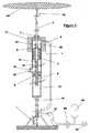
任意の浮揚性の材料で構築され得る浮き(14)は、ガスが入っているまたは入っていない容器を含む。浮きの幾何学的形状は、その水平方向の寸法が大きくかつ相対的にその垂直方向の寸法が小さくなければならない。浮きは、水平方向にそれに近づく水に対して最小限の抵抗を有するように流線形でなければならない。この形状にはいくつかの理由がある。表面積が大きいことにより、浮きが上昇する波から動力学的エネルギーと位置エネルギーの双方を吸収することが可能になる。浮きは、波が小さく上昇するだけでその最大浮力を発揮する。流線形であることにより、波の動きまたは辺りに広がる潮流によってあるいは嵐のときにそれが沈められる際に生じる浮きの水平方向の変位が最小限になる。上記に記載される浮きは、連結金具またはUリンクまたはトグルによって、それ自体が同様の方法でロッドまたは管(3)の一端に接続される可撓性のロープまたは鎖またはロッドまたは管(15)に接続される。このロッドまたは管の他端はピストン(2)の一端に堅く接続される。ピストン(2)は、ピストン(2)の中またはそれに近接して設置されたチェック弁(9)に流体が移動することができるように中空である。ロッドまたは管(3)より直径が大きい別のロッドまたは管(4)がピストン(2)の他端に堅く接続される。本発明の好ましい実施形態では、ロッドまたは管(4)は、その長さの範囲内にまたはその端部に設置されたチェック弁(10)を備える管である。以下に記載される別の実施形態では、それはチェック弁のないロッドまたは密閉された管である。ロッドまたは管(3、4)の一部およびチェック弁(9、10)と協同するピストン(2)はシリンダ(1)の中に密閉され、その中でピストン(2)は自由に摺動することができる。シリンダ(1)はいかなる長さであってもよく、それはロッドまたは管(3、4)が通ることができるようにする以外は両端で閉鎖され、一端に取り付けられた浮揚性のつば(13)を有する。シリンダの各閉鎖端部には、好ましく調節されたクリアランスタイプを含めた任意のタイプのシールであり得るシール(7、8)が装着される。ピストン(2)はこのシリンダ(1)を2つの汲み上げチャンバ(10と18)に分ける。ポートまたは開口(11および12)によって、流体が中空のピストンおよびチェック弁(9)を介してこれらのチャンバ間を移動することが可能になる。ロッドまたは管(3)に隣接するシリンダ(1)の端部は、排出パイプ(5)に接続された開口またはポートを有する。排出パイプ(5)は、全てが可撓性のパイプでも部分的に剛性で部分的に可撓性であってもよい。排出パイプ(5)の他端は岸に直接接続されるか、あるいは好ましい実施形態では海底でポンプをその土台に接続するまたはそこから分離させる機構に接続されるかのどちらかであってよい。この機構はこの本文において後に記載する。好ましい実施形態において、排出パイプ(21)は海面から遠隔式に作動可能である三方サービス弁(29)に接続される。1つまたは複数の排出パイプ(21)にその長さに沿った任意の地点で蓄圧器(30)が接続される。支持構造体(17)が、一端でシリンダ(1)におよびその他端で可撓性のジョイント(16)に堅く接続される。この支持構造体(17)は海に対して開放される場合がある、あるいはその表面に取り付けられたフィルタまたはスクリーンを含む場合がある。別の実施形態において、それは入り口ポート(6)を備えその端部が閉鎖されたシリンダであってよい。この入り口ポートは任意の流体源に接続される場合、または海に対して開放される場合、あるいは任意のタイプの濾過または前処理設備に接続される場合がある。
ポンプの作動A float (14) that may be constructed of any buoyant material includes a container with or without gas. The float geometry must have a large horizontal dimension and a relatively small vertical dimension. The float must be streamlined to have minimal resistance to water approaching it in the horizontal direction. There are several reasons for this shape. The large surface area makes it possible to absorb both kinetic energy and potential energy from the wave rising up. Floats exert their maximum buoyancy just by raising the waves small. Being a streamline minimizes the horizontal displacement of the float caused by wave motion or tidal currents or when it is sunk during a storm. The buoy described above is a flexible rope or chain or rod or tube (15) which is itself connected to one end of a rod or tube (3) in a similar manner by a fitting or U-link or toggle. Connected to. The other end of this rod or tube is rigidly connected to one end of the piston (2). The piston (2) is hollow so that fluid can move to a check valve (9) installed in or close to the piston (2). Another rod or tube (4) having a larger diameter than the rod or tube (3) is rigidly connected to the other end of the piston (2). In a preferred embodiment of the invention, the rod or tube (4) is a tube with a check valve (10) installed within its length or at its end. In another embodiment described below, it is a rod or a sealed tube without a check valve. A part of the rod or tube (3, 4) and the piston (2) cooperating with the check valve (9, 10) are sealed in the cylinder (1), in which the piston (2) slides freely. be able to. The cylinder (1) can be of any length, it is closed at both ends except allowing a rod or tube (3, 4) to pass through and a buoyant collar (13) attached at one end. Have Each closed end of the cylinder is fitted with a seal (7, 8), which can be any type of seal, preferably including a regulated clearance type. The piston (2) divides this cylinder (1) into two pumping chambers (10 and 18). Ports or openings (11 and 12) allow fluid to move between these chambers via the hollow piston and check valve (9). The end of the cylinder (1) adjacent to the rod or tube (3) has an opening or port connected to the discharge pipe (5). The discharge pipe (5) may be an all-flexible pipe or partly rigid and partly flexible. The other end of the discharge pipe (5) can either be connected directly to the shore, or in a preferred embodiment, connected to a mechanism that connects the pump to its base or separates it from the seabed. This mechanism is described later in this text. In a preferred embodiment, the discharge pipe (21) is connected to a three-way service valve (29) that is remotely operable from sea level. A pressure accumulator (30) is connected to one or more discharge pipes (21) at any point along its length. A support structure (17) is rigidly connected to the cylinder (1) at one end and to the flexible joint (16) at the other end. This support structure (17) may be open to the sea or may include a filter or screen attached to its surface. In another embodiment it may be a cylinder with an inlet port (6) closed at its end. This inlet port may be connected to any fluid source, open to the sea, or connected to any type of filtration or pretreatment equipment.
Pump operation
本発明の作動手段をより適切に説明するために、浮き(14)が静止状態であり蓄圧器(30)がポンプの環境の周囲圧力を超えて加圧され、蓄圧器(30)に流体が充填されポンプが流体で満たされると仮定することから始める。このような状況でチェック弁(10)が閉鎖され、蓄圧器(30)によって汲み上げチャンバ(19)が加圧される。汲み上げチャンバ(18)も同様にピストン(2)を介して均等に加圧される。その端部間の圧力差によってロッドまたは管(3)に軸方向の力が生成される。同様に但し反対方向に、その端部間の圧力差によってロッドまたは管(4)に軸方向の力が生成される。ロッドまたは管(4)はロッドまたは管(3)より直径が大きく、これによりロッドまたは管(4)に対する力の大きさはより大きくなる。これらの力は結果として作動可能に接続された浮き(14)に対して最終的に下向きの力となる。この力は、システムを均衡状態に保つために浮き(14)の浮力の一部によって均衡される。この手段によって、浮きから土台まで一連となったポンプ全体が緊張状態で維持される。ここで上昇する波が浮き(14)に対して作用すると仮定すると、上昇する水の動力学的エネルギーと増大する浮きの浮力の双方によって上向きの力が生成される。この力は上記に言及した下向きの力を上回り、作動可能に接続されたピストン(2)と協同する浮き(14)がシリンダ(1)に対して移動し、汲み上げチャンバ(19)の容積を縮小させチェック弁(9)を閉鎖し、これにより流体を排出パイプ(5)へと排出する。同時に汲み上げチャンバ(18)の容積が増大し、チェック弁(10)およびポート(11)を介して流体をそこに進入させる。浮きが波の頂部に達し波がその後下降し始めるとき、チェック弁(9)が開放しチェック弁(10)が閉鎖し、ロッドまたは管(3および4)の直径の差に起因する上記に言及した力によってピストン(2)がシリンダ(1)に対して最初の往復動作と反対方向に動き、その結果汲み上げチャンバ(19)を拡張させ汲み上げチャンバ(18)を収縮させる。流体はしたがって、ポート(11)、チェック弁(9)およびポート(12)を介して汲み上げチャンバ(18)から汲み上げチャンバ(19)へと中空のピストンの中を通過する。ポンプはこのようにリセットされ、次の上昇する波によって生じる次の汲み上げ往復動作のための準備をする。次の汲み上げ往復動作が始まるまたは終わるとき、ピストン(2)はシリンダ(1)の長さのいずれの位置にあってもよい。この手段によって、例えば潮によって生じるいかなる水の深さの変動に対してもポンプは自動調整する。三方向サービス弁(29)は、デバイスを保守または修理のために回収することができるように、残りの1つまたは複数の排出パイプ(21)からそれを隔離するのに使用される。In order to better describe the actuating means of the present invention, the float (14) is stationary and the accumulator (30) is pressurized above the ambient pressure of the pump environment and fluid is accumulated in the accumulator (30). Start by assuming that the pump is filled with fluid. In such a situation, the check valve (10) is closed and the pumping chamber (19) is pressurized by the accumulator (30). The pumping chamber (18) is likewise equally pressurized through the piston (2). The pressure difference between the ends creates an axial force on the rod or tube (3). Similarly, but in the opposite direction, an axial force is generated on the rod or tube (4) by the pressure difference between its ends. The rod or tube (4) is larger in diameter than the rod or tube (3), thereby increasing the magnitude of the force on the rod or tube (4). These forces eventually result in a downward force on the operably connected float (14). This force is balanced by a portion of the buoyancy of the buoy (14) to keep the system in equilibrium. By this means, the entire pump from the float to the base is maintained in tension. Assuming that the rising waves now act on the float (14), an upward force is generated by both the kinetic energy of the rising water and the increasing buoyancy of the float. This force exceeds the downward force mentioned above, the float (14) cooperating with the operatively connected piston (2) moves relative to the cylinder (1), reducing the volume of the pumping chamber (19) The check valve (9) is closed, and the fluid is thereby discharged into the discharge pipe (5). At the same time, the volume of the pumping chamber (18) increases, allowing fluid to enter through the check valve (10) and port (11). When the float reaches the top of the wave and the wave then begins to descend, the check valve (9) opens and the check valve (10) closes, referring to the above due to the difference in the diameter of the rods or tubes (3 and 4) The resulting force causes the piston (2) to move in the opposite direction to the first reciprocating motion with respect to the cylinder (1), thereby expanding the pumping chamber (19) and causing the pumping chamber (18) to contract. The fluid thus passes through the hollow piston from the pumping chamber (18) to the pumping chamber (19) via port (11), check valve (9) and port (12). The pump is thus reset and prepared for the next pumping reciprocation caused by the next rising wave. When the next pumping reciprocation begins or ends, the piston (2) may be in any position along the length of the cylinder (1). By this means, the pump automatically adjusts for any variation in water depth caused by, for example, tides. The three-way service valve (29) is used to isolate it from the remaining one or more exhaust pipes (21) so that the device can be retrieved for maintenance or repair.
次に図2を参照する。
ポンプの記載Reference is now made to FIG.
Description of pump
この図は、入り口とチェック弁の位置が異なるデバイスの別の実施形態を示す。この記載は以下の変更を除いて図1における実施形態の記載と同様である。この実施形態では、入り口ポート(31)は排出パイプ(5)とは反対のシリンダ(1)の端部に位置している。このポート内にまたはこれに隣接して入り口チェック弁(32)が配置されている。ロッドまたは管(4)は、チェック弁のないロッドまたは密閉された管である。ポート(31)は任意の流体源に接続される場合、または海に対して開放される場合、あるいは任意のタイプの濾過または前処理設備に接続される場合がある。
ポンプの作動This figure shows another embodiment of the device with different inlet and check valve positions. This description is the same as the description of the embodiment in FIG. 1 except for the following changes. In this embodiment, the inlet port (31) is located at the end of the cylinder (1) opposite the discharge pipe (5). An inlet check valve (32) is located in or adjacent to this port. The rod or tube (4) is a rod or sealed tube without a check valve. Port (31) may be connected to any fluid source, open to the sea, or connected to any type of filtration or pretreatment equipment.
Pump operation
ポンプの作動は、入ってくる流体が今度はポート(31)およびチェック弁(32)を通過して直接汲み上げチャンバ(18)へと入ること以外は図1の実施形態と同様である。 The operation of the pump is similar to the embodiment of FIG. 1 except that the incoming fluid now passes directly through the port (31) and check valve (32) into the pumping chamber (18).
上記に言及した実施形態はいずれも、シリンダに作動可能に接続された浮きと海底に作動可能に接続されたピストンとを逆さにした位置で有するポンプによって構成される場合もある。すなわちロッドまたは管(3)を可撓性のジョイント(16)に接続することができ、シリンダ(1)を可撓性のロープまたは鎖またはロッドまたは管(15)に接続することができる。そして、排出パイプ(5)を入口ポート(6)に接続し、チャンバ(19)側の圧力をチャンバ(18)側の圧力より大きくする。その他のポンプの構成および作動は基本的に上記に記載したものと同様である。
ポンプを海底に取り付ける機構の記載
Any of the embodiments mentioned above may be constituted by a pump having a float operatively connected to a cylinder and a piston operably connected to the seabed in an inverted position. That is, the rod or tube (3) can be connected to a flexible joint (16) and the cylinder (1) can be connected to a flexible rope or chain or rod or tube (15).Then, the discharge pipe (5) is connected to the inlet port (6), and the pressure on the chamber (19) side is made larger than the pressure on the chamber (18) side. Other pump configurations and operations are basically the same as those described above.
Description of the mechanism for attaching the pump to the seabed
次に図3を参照する。 Reference is now made to FIG.
図3は、ポンプを土台に接続するまたはそこから分離させることができる機構を示す。 FIG. 3 shows a mechanism by which the pump can be connected to or detached from the foundation.
トグル、Uリンク、鎖、ロープ、連結金具または任意のタイプの可撓性部材であり得る可撓性ジョイント(16)によってポンプ組立体がこの機構に接続される。可撓性ジョイント(16)の他端はピン(25)の一端に堅く接続される。ピン(25)はその長さの一部を貫通して中空である。排出パイプ(5)がその中空の部分と連通するようにピン(25)に接続される。さらにピンに沿ったところに位置するポート(33)は、ピンの中空の部分およびピンの外部とも連通する。ピン(25)の他端は溝であり、先細になり、滑車(22)およびロック(24)上の索道器を介して海面までおよびこれを超えて延出するロープまたはつなぎ鎖またはケーブルまたは鎖であり得る作動ライン(23)に接続される。このピン(25)は容器(26)に収容され、容器は2つのシール(34)を装備する。シール(34)の間は、排出パイプ(21)と連通する容器(35)内の環状の溝である。ロック(24)は、枢軸を中心に水平方向に回転しピン(25)上の溝に係合するように成形される。ロック(24)内には索道器が内蔵されている。容器(26)は、支持構造体(28)によって土台(27)に堅く取り付けられる。
The pump assembly is connected to this mechanism by a flexible joint (16), which can be a toggle, U-link, chain, rope, coupling hardware or any type of flexible member. The other end of the flexible joint (16) is rigidly connected to one end of the pin (25). The pin (25) is hollow through part of its length. A discharge pipe (5) is connected to the pin (25) so as to communicate with its hollow part. Further, the port (33) located along the pin communicates with the hollow portion of the pin and the outside of the pin. The other end of the pin (25) is a groove, tapering, rope or tether or cable or chain that extends to and beyond the sea level via acableway on the pulley (22) and lock (24) Connected to an operating line (23) which may be This pin (25) is housed in a container (26), which is equipped with two seals (34). Between the seals (34) is an annular groove in the container (35) communicating with the discharge pipe (21). The lock (24) is shaped to rotate horizontally about the pivot and engage the groove on the pin (25). Acable tractor is built in the lock (24). The container (26) is rigidly attached to the base (27) by the support structure (28).
図3はまた、コンクリート、金属または任意の他の高密度材料から構築される重力を利用した土台であり得る土台(27)を示す。土台(27)はまた、海底の下に設置されるねじ、杭および板を含めた任意の種類の錨であってもよい。
海底にポンプと取り付ける機構の作動FIG. 3 also shows a foundation (27) that can be a gravity-based foundation constructed from concrete, metal or any other high density material. The foundation (27) may also be any type of dredging including screws, piles and plates installed under the seabed.
Actuation of a mechanism for attaching a pump to the seabed
図3に示される土台および機構は既知の配向で海底に設置される。ポンプを配備するために、作動ライン(23)の上端はモーターボートまたは他の船に接続される。モーターボートは作動ライン(23)に張力を加え、よってピン(25)およびしたがって作動可能に取り付けられたポンプを容器(26)へ向かってその中に入るように下に引っ張る。モーターボートは、作動ライン(23)に対してなお張力を維持しながらデバイスの周囲を弧を描いて航行する。モーターボートがこのように動くことによって作動ライン(23)がロック(24)の索道器部分を支え、これによりロックをその枢軸を中心に回転させピン(25)の溝と係合させる。作動ライン(23)は次にモーターボートから切り離され、後に回収するために用意された面で任意の物体に取り付けられる。モーターボートがデバイスを配備するのに使用されたのと反対方向に弧を描いて航行し、ロック(24)をピン(25)の溝から分離させ、よって容器(26)からデバイスを解放させること以外は、デバイスの回収は同様の方法で行なわれる。図1の浮揚性のつば(13)によって分離されたポンプはこの面まで上昇する。
嵐のときの1つまたは複数のポンプの作動
The foundation and mechanism shown in FIG. 3 are installed on the seabed in a known orientation. In order to deploy the pump, the upper end of the working line (23) is connected to a motorboat or other ship. The motor boat tensions the actuation line (23), thus pulling the pin (25) and thus the operably attached pump down into the vessel (26) and into it. The motorboat sails in an arc around the device while still maintaining tension against the working line (23). As the motorboat moves in this manner, the actuation line (23) supports thecableway portion of the lock (24), thereby rotating the lock about its pivot and engaging the groove in the pin (25). The actuation line (23) is then disconnected from the motorboat and attached to any object with a surface prepared for later retrieval. Other than navigating in the opposite direction that the motorboat was used to deploy the device, separating the lock (24) from the groove in the pin (25) and thus releasing the device from the container (26) The device recovery is performed in a similar manner. The pump separated by the buoyant collar (13) of FIG.
Operation of one or more pumps during a storm
1つまたは複数の排出パイプ(21)に沿った任意の地点、但し蓄圧器(30)を超える地点に1つまたは複数の弁が装着することができる。この1つまたは複数の弁は、ポンプの排出パイプ(5)から外に流体が流れ出るのを阻止するために閉鎖され、よってその汲み上げ往復動作でのピストン(2)の動きを阻止することができる。蓄圧器からの加圧された流体が往復動作の戻り行程を作動させ続け、その結果ピストン(2)に作動可能に接続された浮き(14)を最も低い波の谷間のレベルまで下降させる。波が上昇する際浮きはそれより下に沈み、この手段によって、嵐によって引き起こされる波頂に生成される大きな力による損傷からそれ自体が保護される。ピストンおよびしたがって作動可能に接続された浮きの動きを制限するために、弾性の止め具がシリンダ(1)内に装着されるまたはピストン(2)の端部に取り付けられる場合もある。One or more valves can be mounted at any point along the one or more discharge pipes (21), but beyond the accumulator (30). The valve or valves are closed to prevent fluid from flowing out of the pump discharge pipe (5), thus preventing movement of the piston (2) in its pumping reciprocation. . The pressurized fluid from the accumulator continues to actuate the return stroke of the reciprocating action, thereby lowering the float (14) operatively connected to the piston (2) to the lowest wave valley level. As the wave rises, the float sinks below it, and this measure protects itself from damage caused by the large forces generated at the crest caused by the storm. In order to limit the movement of the piston and thus the operably connected float, a resilient stop may be mounted in the cylinder (1) or attached to the end of the piston (2).
1 シリンダ
2 ピストン
3、4 ロッドまたは管
5 排出パイプ
6 入り口ポート
7、8 シール
9、10 チェック弁
11、12 ポート
13 つば
14 浮き
15 ロッドまたは管
16 ジョイント
17 支持構造体
18、19 チャンバ
21 排出パイプ
22 滑車
23 作動ライン
24 ロック
25 ピン
26、35 容器
27 土台
28 支持構造体
29、36 三方サービス弁
30 蓄圧器
31 入り口ポート
32 入り口チェック弁
33 ポート
34 シールDESCRIPTION OF
Claims (6)
Translated fromJapanese前記浮きまたは海底の一方に接続され流体入り口および流体排出口を有する密閉式のシリンダと、
前記シリンダ内に配置されその中で長手方向に可動であり、長手方向にそこを貫通して延在する通路を有するピストンと、
前記ピストンの中を通る通路と連通するように配置された流体チェック弁と、
前記ピストンの一端に接続され、前記密閉式シリンダの一端を通って延出し、さらに前記浮きまたは海底の他方に接続される、一部が管形状の第1ロッドまたは管と、
前記ピストンの他端に接続され、前記第1ロッドまたは管の直径より大きな直径を有し、前記密閉式のシリンダの他端を通って延出する、少なくとも一部が管形状の第2ロッドまたは管とを備える浮き作動式の往復ポンプ。Floating,
A sealed cylinder connected to one of the float or the seabed and having afluid inlet and afluid outlet;
A piston disposed in the cylinder, movable in the longitudinal direction therein, and having a passage extending therethrough in the longitudinal direction;
A fluid check valve arranged to communicate with a passage through the piston;
Is connected toone end of the pistonextends through an end of the closed cylinder and further connected to the other of the float or theseabed, a first rod ortube part a tubular shape,
A second rod or tubeconnected to the other end of the piston, having a diameter greater than that of the first rod or tube and extending through the other end of the sealed cylinder, at least partially Floating operation type reciprocating pump comprising a tube.
前記ロープが前記ピンのための容器の中に通され、海底に可動に取り付けられた滑車を通るように通され、そこから前記ロック部材に内蔵された索道器の中に通され、前記ロープの他端が水面まで延出しており、前記ロープの他端に張力を加えると、前記中空のピンが前記容器内へと挿入されて、前記中空のピンの溝が前記容器より下方に位置し、前記ロープによって前記索道器を介して前記ロック部材を回転させて前記溝と係合させると、前記中空のピンは前記容器に固定され、前記ロープによって前記ロック部材を反対側に回転させると、前記ロック部材は前記溝から離れ、
前記中空のピンが前記容器に固定された状態では、前記ピンの中空の部分が前記流体排出口に設けられた排出パイプに接続されかつそれと連通し、前記ピンが前記中空の部分とその外側との間にポートを有し、前記容器が前記ピン内の前記ポートと連通するように中に通路を有し、前記通路が別の排出パイプに接続されかつそれと連通する、請求項1〜5のいずれかに記載のポンプ。The connection part to the seabed is a sealed hollow pin, one end of which is connected tothe bottom ofthe main body of the pumpby a flexiblemember and the other end is connected to one end of the rope, and the hollowpin is inserted A fixed container connected to the seabed, and a locking member attached to the container so as to be rotatable in a horizontal direction around a pivot, anda groove engaging with the locking member at one end of the hollow pin Is formed,
The rope is passed through a container for the pin, passed througha pulleymovably attached to the seabed, and from there througha cableway incorporated in the locking member, the other endhas been extended up to the watersurface, when tension is applied to the other end of the rope, said hollow pin is inserted into the container, a groove of said hollow pin is positioned below the container When the lock member is rotated by the rope via the cableway and engaged with the groove, the hollow pin is fixed to the container, and the lock member is rotated to the opposite side by the rope. The locking member is separated from the groove;
In the state where the hollow pinis fixed to the container, the hollow portion of the pin is connected to and communicateswith a discharge pipeprovided at the fluid discharge port, and the pin is connected to the hollow portion and the outside thereof. have ports between the container has a passage in so as to communicate with the port in the pins, the path is the same communication and is connected to another exhaust pipe, ofclaims 1 to 5 The pump according to any one.
Applications Claiming Priority (3)
| Application Number | Priority Date | Filing Date | Title |
|---|---|---|---|
| GB0812739AGB2461859B (en) | 2008-07-11 | 2008-07-11 | Wave actuated pump and means of connecting same to the seabed |
| GB0812739.1 | 2008-07-11 | ||
| PCT/GB2009/001718WO2010004293A2 (en) | 2008-07-11 | 2009-07-10 | Wave actuated pump and means of connecting same to the seabed |
Publications (3)
| Publication Number | Publication Date |
|---|---|
| JP2011527402A JP2011527402A (en) | 2011-10-27 |
| JP2011527402A5 JP2011527402A5 (en) | 2014-02-20 |
| JP5574298B2true JP5574298B2 (en) | 2014-08-20 |
Family
ID=39722151
Family Applications (1)
| Application Number | Title | Priority Date | Filing Date |
|---|---|---|---|
| JP2011517231AExpired - Fee RelatedJP5574298B2 (en) | 2008-07-11 | 2009-07-10 | Wave actuated pump and means for connecting it to the seabed |
Country Status (16)
| Country | Link |
|---|---|
| US (1) | US8668472B2 (en) |
| EP (1) | EP2310665B1 (en) |
| JP (1) | JP5574298B2 (en) |
| CN (1) | CN102165182B (en) |
| AP (1) | AP2011005576A0 (en) |
| AT (1) | ATE551523T1 (en) |
| AU (1) | AU2009269812B2 (en) |
| BR (1) | BRPI0915741A2 (en) |
| CA (1) | CA2729927C (en) |
| DK (1) | DK2310665T3 (en) |
| ES (1) | ES2386674T3 (en) |
| GB (1) | GB2461859B (en) |
| NZ (1) | NZ590907A (en) |
| PT (1) | PT2310665E (en) |
| WO (1) | WO2010004293A2 (en) |
| ZA (1) | ZA201100662B (en) |
Families Citing this family (29)
| Publication number | Priority date | Publication date | Assignee | Title |
|---|---|---|---|---|
| GB0915779D0 (en)* | 2009-09-09 | 2009-10-07 | Dartmouth Wave Energy Ltd | Improvements relating to wave powered pumping devices |
| KR101813305B1 (en) | 2010-08-16 | 2017-12-28 | 케토 아이피 피티와이 리미티드 | Wave energy conversion |
| CN103089530B (en)* | 2011-11-01 | 2015-07-08 | 徐泽辰 | Wave energy conversion device and system |
| GB2501239A (en)* | 2012-03-19 | 2013-10-23 | Robert Tillotson | Wave operated pump with secondary chamber providing restoring force |
| TWI485321B (en) | 2012-10-31 | 2015-05-21 | Ind Tech Res Inst | Wave power generation system and hydraulic member |
| WO2014078064A1 (en)* | 2012-11-15 | 2014-05-22 | Atmocean, Inc. | Hydraulic pressure generating system |
| US9777701B2 (en) | 2013-04-22 | 2017-10-03 | The Regents Of The University Of California | Carpet of wave energy conversion (CWEC) |
| AU2014257189A1 (en)* | 2013-04-22 | 2015-12-03 | Mohammad-Reza ALAM | Carpet of wave energy conversion (CWEC) |
| CN103291531B (en)* | 2013-07-02 | 2015-09-30 | 清华大学 | A kind of wave energy hydraulic pump with water tank |
| CN104153937B (en)* | 2014-07-25 | 2016-10-05 | 浙江大学 | A kind of Wave energy collecting device adapting to tidal level change |
| US9702336B2 (en)* | 2014-10-03 | 2017-07-11 | Stephen J. Markham | Low profile ocean pump array generation station |
| US9644600B2 (en)* | 2015-09-29 | 2017-05-09 | Fahd Nasser J ALDOSARI | Energy generation from buoyancy effect |
| CN105298731B (en)* | 2015-10-26 | 2017-10-31 | 清华大学 | A kind of float-type Wave energy converting device |
| CN109562961B (en) | 2016-06-10 | 2022-05-27 | 欧奈卡技术公司 | System and method for desalination of water by reverse osmosis |
| SE540263C2 (en)* | 2016-06-13 | 2018-05-15 | Novige Ab | Apparatus for harvesting energy from waves |
| US10443593B2 (en)* | 2017-02-13 | 2019-10-15 | Walter Chen | Fresh water transport method utilizing anchored buoyant units powered by the changing height of a local tide |
| CN107387303A (en)* | 2017-08-29 | 2017-11-24 | 边令仁 | One kind combination cage type Wave power generation device |
| CN107654333A (en)* | 2017-10-31 | 2018-02-02 | 浙江海洋大学 | A hydraulic wave power generation device |
| US11156201B2 (en)* | 2018-05-17 | 2021-10-26 | Lone Gull Holdings, Ltd. | Inertial pneumatic wave energy device |
| CN108561265A (en)* | 2018-06-22 | 2018-09-21 | 上海交通大学 | A kind of anti-wave power generator of sea swing type and its design method |
| US10837420B2 (en) | 2018-10-31 | 2020-11-17 | Loubert S. Suddaby | Wave energy capture device and energy storage system utilizing a variable mass, variable radius concentric ring flywheel |
| US10788011B2 (en) | 2018-10-31 | 2020-09-29 | Loubert S. Suddaby | Wave energy capture device and energy storage system utilizing a variable mass, variable radius concentric ring flywheel |
| US11001357B2 (en)* | 2019-07-02 | 2021-05-11 | Raytheon Company | Tactical maneuvering ocean thermal energy conversion buoy for ocean activity surveillance |
| SE543965C2 (en)* | 2020-02-20 | 2021-10-12 | Novige Ab | Power take-off apparatus and wave energy converter for harvesting energy from waves |
| FR3109610B1 (en)* | 2020-04-23 | 2022-04-08 | Air Liquide | Compression apparatus and filling station comprising such apparatus |
| KR102375024B1 (en)* | 2020-11-25 | 2022-03-17 | 한국전력공사 | Sea water pumped hydro power system with wave pump |
| US12345227B1 (en) | 2020-12-02 | 2025-07-01 | Stanton J. M. Collins, Jr. | Modular valvular conduit upwelling system |
| PE20251127A1 (en) | 2022-09-11 | 2025-04-22 | Alexander V Soloviev | Mitigation of the adverse effects of coastal upwelling in an artificial descent system |
| CN118728623B (en)* | 2024-08-01 | 2025-01-28 | 海南大学 | A compressed air energy storage device that can predict wave strength |
Family Cites Families (24)
| Publication number | Priority date | Publication date | Assignee | Title |
|---|---|---|---|---|
| US2605712A (en)* | 1948-11-06 | 1952-08-05 | Atlantic Refining Co | Hydraulic pumping system for producing from overlying reservoirs |
| US2901980A (en)* | 1957-03-22 | 1959-09-01 | James M Jordan | Foot pump |
| US3078804A (en)* | 1959-06-08 | 1963-02-26 | Kobe Inc | Fluid operated pump system with external pump passages |
| US4076463A (en)* | 1976-10-26 | 1978-02-28 | Mordechai Welczer | Wave motor |
| US4326840A (en)* | 1980-03-10 | 1982-04-27 | University Of Delaware | Wave driven pump |
| US4382716A (en)* | 1981-03-02 | 1983-05-10 | Troy Miller | Blowout recovery system |
| FR2518639A1 (en)* | 1981-12-21 | 1983-06-24 | Inst Francais Du Petrole | PROCESS FOR RECOVERING POLYMETALLIC COMPOUNDS REJECTED BY AN UNDERWATER HYDROTHERMAL SOURCE AND DEVICES FOR IMPLEMENTING THE SAME |
| JPS60261982A (en)* | 1984-06-11 | 1985-12-25 | Yasuhiro Manabe | Wave powered prime mover |
| US4754157A (en)* | 1985-10-01 | 1988-06-28 | Windle Tom J | Float type wave energy extraction apparatus and method |
| US4883411A (en)* | 1988-09-01 | 1989-11-28 | Windle Tom J | Wave powered pumping apparatus and method |
| US5179837A (en)* | 1991-04-02 | 1993-01-19 | Sieber J D | Wave powered energy generator |
| WO1994015096A1 (en)* | 1991-04-02 | 1994-07-07 | Sieber Joseph D | Wave powered energy generator |
| KR950010463B1 (en)* | 1992-05-22 | 1995-09-18 | 임명식 | Wave Power Generator Using Ocean Waves |
| US5842838A (en)* | 1996-11-04 | 1998-12-01 | Berg; John L. | Stable wave motor |
| WO1999013238A1 (en)* | 1997-09-11 | 1999-03-18 | Ismael Rego Espinoza | Machine for producing kinetic energy |
| DE69817608D1 (en)* | 1997-12-03 | 2003-10-02 | William Dick | SEA wave transducer |
| CN1274045A (en)* | 1999-05-18 | 2000-11-22 | 张振文 | Hydroelectric equipment and method for generating power thereof |
| FR2800423B1 (en)* | 1999-10-27 | 2002-05-03 | Jean Marc Albert Janody | SUBMERSIBLE SUCTION-REFOULING PISTON PUMP FOR LIQUIDS ACTIVATED BY THE AGITATION ENERGY OF ITS IMMERSION MEDIUM |
| GB2428747B (en)* | 2005-08-02 | 2009-10-21 | Seawood Designs Inc | Wave energy conversion system |
| CN101292086B (en)* | 2005-08-17 | 2013-09-25 | 刻托知识产权有限公司 | A device for harvesting wave energy in a body of water with a water surface |
| AU2006320515C1 (en)* | 2005-12-01 | 2012-03-01 | Ocean Power Technologies, Inc. | Wave energy converter utilizing internal reaction mass and spring |
| GB2473223A (en)* | 2007-01-25 | 2011-03-09 | Dartmouth Wave Energy Ltd | Height adjustable wave powered pump |
| CA2631297A1 (en)* | 2008-05-14 | 2009-11-14 | Gerald J. Vowles | Wave-powered, reciprocating hose peristaltic pump |
| WO2009140615A1 (en)* | 2008-05-15 | 2009-11-19 | Ocean Energy Systems, Llc | Wave energy recovery system |
- 2008
- 2008-07-11GBGB0812739Apatent/GB2461859B/ennot_activeExpired - Fee Related
- 2009
- 2009-07-10NZNZ590907Apatent/NZ590907A/ennot_activeIP Right Cessation
- 2009-07-10ATAT09784678Tpatent/ATE551523T1/enactive
- 2009-07-10JPJP2011517231Apatent/JP5574298B2/ennot_activeExpired - Fee Related
- 2009-07-10BRBRPI0915741Apatent/BRPI0915741A2/ennot_activeApplication Discontinuation
- 2009-07-10EPEP09784678Apatent/EP2310665B1/ennot_activeNot-in-force
- 2009-07-10USUS13/002,317patent/US8668472B2/enactiveActive
- 2009-07-10DKDK09784678.6Tpatent/DK2310665T3/enactive
- 2009-07-10AUAU2009269812Apatent/AU2009269812B2/ennot_activeCeased
- 2009-07-10WOPCT/GB2009/001718patent/WO2010004293A2/enactiveApplication Filing
- 2009-07-10APAP2011005576Apatent/AP2011005576A0/enunknown
- 2009-07-10ESES09784678Tpatent/ES2386674T3/enactiveActive
- 2009-07-10PTPT09784678Tpatent/PT2310665E/enunknown
- 2009-07-10CNCN200980134568.XApatent/CN102165182B/ennot_activeExpired - Fee Related
- 2009-07-10CACA2729927Apatent/CA2729927C/enactiveActive
- 2011
- 2011-01-26ZAZA2011/00662Apatent/ZA201100662B/enunknown
Also Published As
| Publication number | Publication date |
|---|---|
| US20110097220A1 (en) | 2011-04-28 |
| US8668472B2 (en) | 2014-03-11 |
| CA2729927C (en) | 2017-05-16 |
| JP2011527402A (en) | 2011-10-27 |
| ATE551523T1 (en) | 2012-04-15 |
| WO2010004293A2 (en) | 2010-01-14 |
| CN102165182A (en) | 2011-08-24 |
| EP2310665A2 (en) | 2011-04-20 |
| NZ590907A (en) | 2012-06-29 |
| EP2310665B1 (en) | 2012-03-28 |
| GB0812739D0 (en) | 2008-08-20 |
| BRPI0915741A2 (en) | 2015-11-03 |
| GB2461859A (en) | 2010-01-20 |
| ES2386674T3 (en) | 2012-08-24 |
| GB2461859B (en) | 2010-08-04 |
| PT2310665E (en) | 2012-05-30 |
| AU2009269812A1 (en) | 2010-01-14 |
| CN102165182B (en) | 2014-02-26 |
| DK2310665T3 (en) | 2012-07-16 |
| AU2009269812B2 (en) | 2012-09-06 |
| HK1155501A1 (en) | 2012-05-18 |
| AP2011005576A0 (en) | 2011-02-28 |
| CA2729927A1 (en) | 2010-01-14 |
| WO2010004293A3 (en) | 2011-04-14 |
| ZA201100662B (en) | 2011-10-26 |
Similar Documents
| Publication | Publication Date | Title |
|---|---|---|
| JP5574298B2 (en) | Wave actuated pump and means for connecting it to the seabed | |
| US7980832B2 (en) | Wave energy converter | |
| CN101617118B (en) | Hydro column | |
| US7969033B2 (en) | Buoyancy energy cell | |
| AU2009272416B2 (en) | Wave powered generator | |
| US8125097B1 (en) | Electrical generation using vertical movement of a mass | |
| US9309860B2 (en) | Wave energy conversion device | |
| US20070158950A1 (en) | Hydroelectric Wave-Energy Conversion System | |
| US20090121486A1 (en) | Tidal Power System | |
| US20100244451A1 (en) | Ocean wave energy to electricity generator | |
| WO2013150320A2 (en) | Mechanical hydraulic electrical floating and grounded system exploiting the kinetic energy of waves (seas-lakes-oceans) and converting it to electric energy and to drinking water | |
| US20110221209A1 (en) | Buoyancy Energy Cell | |
| GB2434409A (en) | Tidal energy system | |
| CN101617119A (en) | Device for recovering wave energy | |
| WO2010122566A2 (en) | Movable water turbine for power generation from sea waves/flowing water | |
| WO2019244753A1 (en) | Wave power generator | |
| RU2080478C1 (en) | Wave-electric power plant | |
| HK1155501B (en) | Wave actuated pump and means of connecting same to the seabed | |
| GB2401405A (en) | A tidal powered device for pumping fluid | |
| CN111927695A (en) | Wave or tidal power generation device | |
| KR20090092794A (en) | Dynamic fluid energy conversion system and method of use |
Legal Events
| Date | Code | Title | Description |
|---|---|---|---|
| A621 | Written request for application examination | Free format text:JAPANESE INTERMEDIATE CODE: A621 Effective date:20120501 | |
| A977 | Report on retrieval | Free format text:JAPANESE INTERMEDIATE CODE: A971007 Effective date:20130618 | |
| A131 | Notification of reasons for refusal | Free format text:JAPANESE INTERMEDIATE CODE: A131 Effective date:20130716 | |
| A601 | Written request for extension of time | Free format text:JAPANESE INTERMEDIATE CODE: A601 Effective date:20131016 | |
| A602 | Written permission of extension of time | Free format text:JAPANESE INTERMEDIATE CODE: A602 Effective date:20131023 | |
| A601 | Written request for extension of time | Free format text:JAPANESE INTERMEDIATE CODE: A601 Effective date:20131115 | |
| A602 | Written permission of extension of time | Free format text:JAPANESE INTERMEDIATE CODE: A602 Effective date:20131122 | |
| A524 | Written submission of copy of amendment under article 19 pct | Free format text:JAPANESE INTERMEDIATE CODE: A524 Effective date:20131216 | |
| TRDD | Decision of grant or rejection written | ||
| A01 | Written decision to grant a patent or to grant a registration (utility model) | Free format text:JAPANESE INTERMEDIATE CODE: A01 Effective date:20140617 | |
| A61 | First payment of annual fees (during grant procedure) | Free format text:JAPANESE INTERMEDIATE CODE: A61 Effective date:20140623 | |
| R150 | Certificate of patent or registration of utility model | Ref document number:5574298 Country of ref document:JP Free format text:JAPANESE INTERMEDIATE CODE: R150 | |
| R250 | Receipt of annual fees | Free format text:JAPANESE INTERMEDIATE CODE: R250 | |
| R250 | Receipt of annual fees | Free format text:JAPANESE INTERMEDIATE CODE: R250 | |
| R250 | Receipt of annual fees | Free format text:JAPANESE INTERMEDIATE CODE: R250 | |
| R250 | Receipt of annual fees | Free format text:JAPANESE INTERMEDIATE CODE: R250 | |
| R250 | Receipt of annual fees | Free format text:JAPANESE INTERMEDIATE CODE: R250 | |
| R250 | Receipt of annual fees | Free format text:JAPANESE INTERMEDIATE CODE: R250 | |
| LAPS | Cancellation because of no payment of annual fees |