JP5573426B2 - Audio processing apparatus, audio processing method, and program - Google Patents
Audio processing apparatus, audio processing method, and programDownload PDFInfo
- Publication number
- JP5573426B2 JP5573426B2JP2010149365AJP2010149365AJP5573426B2JP 5573426 B2JP5573426 B2JP 5573426B2JP 2010149365 AJP2010149365 AJP 2010149365AJP 2010149365 AJP2010149365 AJP 2010149365AJP 5573426 B2JP5573426 B2JP 5573426B2
- Authority
- JP
- Japan
- Prior art keywords
- output device
- representative
- audio
- audio output
- perceived position
- Prior art date
- Legal status (The legal status is an assumption and is not a legal conclusion. Google has not performed a legal analysis and makes no representation as to the accuracy of the status listed.)
- Expired - Fee Related
Links
Images


Classifications
- H—ELECTRICITY
- H04—ELECTRIC COMMUNICATION TECHNIQUE
- H04S—STEREOPHONIC SYSTEMS
- H04S3/00—Systems employing more than two channels, e.g. quadraphonic
- H04S3/008—Systems employing more than two channels, e.g. quadraphonic in which the audio signals are in digital form, i.e. employing more than two discrete digital channels
- H—ELECTRICITY
- H04—ELECTRIC COMMUNICATION TECHNIQUE
- H04N—PICTORIAL COMMUNICATION, e.g. TELEVISION
- H04N13/00—Stereoscopic video systems; Multi-view video systems; Details thereof
- H04N13/30—Image reproducers
- H—ELECTRICITY
- H04—ELECTRIC COMMUNICATION TECHNIQUE
- H04N—PICTORIAL COMMUNICATION, e.g. TELEVISION
- H04N13/00—Stereoscopic video systems; Multi-view video systems; Details thereof
- H04N13/30—Image reproducers
- H04N13/332—Displays for viewing with the aid of special glasses or head-mounted displays [HMD]
- H04N13/341—Displays for viewing with the aid of special glasses or head-mounted displays [HMD] using temporal multiplexing
- H—ELECTRICITY
- H04—ELECTRIC COMMUNICATION TECHNIQUE
- H04N—PICTORIAL COMMUNICATION, e.g. TELEVISION
- H04N5/00—Details of television systems
- H04N5/64—Constructional details of receivers, e.g. cabinets or dust covers
- H04N5/642—Disposition of sound reproducers
- H—ELECTRICITY
- H04—ELECTRIC COMMUNICATION TECHNIQUE
- H04R—LOUDSPEAKERS, MICROPHONES, GRAMOPHONE PICK-UPS OR LIKE ACOUSTIC ELECTROMECHANICAL TRANSDUCERS; DEAF-AID SETS; PUBLIC ADDRESS SYSTEMS
- H04R2499/00—Aspects covered by H04R or H04S not otherwise provided for in their subgroups
- H04R2499/10—General applications
- H04R2499/15—Transducers incorporated in visual displaying devices, e.g. televisions, computer displays, laptops
- H—ELECTRICITY
- H04—ELECTRIC COMMUNICATION TECHNIQUE
- H04S—STEREOPHONIC SYSTEMS
- H04S2400/00—Details of stereophonic systems covered by H04S but not provided for in its groups
- H04S2400/11—Positioning of individual sound objects, e.g. moving airplane, within a sound field
Landscapes
- Engineering & Computer Science (AREA)
- Multimedia (AREA)
- Physics & Mathematics (AREA)
- Acoustics & Sound (AREA)
- Signal Processing (AREA)
- Testing, Inspecting, Measuring Of Stereoscopic Televisions And Televisions (AREA)
- Stereophonic System (AREA)
- Television Receiver Circuits (AREA)
Description
Translated fromJapanese本発明は、音声処理装置、音声処理方法、およびプログラムに関する。 The present invention relates to a voice processing device, a voice processing method, and a program.
近日、左目用画像および右目用画像を表示することによりユーザに立体視画像を知覚させることが可能な3D表示装置が流通している。3D用に制作されるテレビジョン映像や映画が増加傾向にあること、2D画像を3D画像に変換する技術が盛んに研究されていることなどから、3D表示装置は今後さらに普及すると予想される。なお、3D表示装置について記載された文献として下記の特許文献1が挙げられる。 In the near future, 3D display devices that allow a user to perceive a stereoscopic image by displaying a left-eye image and a right-eye image are in circulation. 3D display devices are expected to become more widespread in the future, as television images and movies produced for 3D are on the rise, and technology for converting 2D images into 3D images is actively researched. In addition, the following
また、音声については、5.1chのようにマルチチャンネル化されたシステムが存在する。このシステムでは、左右のフロントスピーカ、左右のリアスピーカ、センタースピーカなどの複数のスピーカに、各スピーカ用に生成された音声を出力させることにより、ユーザに臨場感のある音場を提供することが可能である。 As for audio, there is a multi-channel system such as 5.1ch. In this system, it is possible to provide a user with a realistic sound field by outputting sound generated for each speaker to a plurality of speakers such as left and right front speakers, left and right rear speakers, and a center speaker. Is possible.
しかし、2D画像を3D画像に変換する場合、2D画像用の音声と変換後の3D画像との連携が疎になってしまうことが懸念される。また、3D画像用の音声は3D画像を考慮して制作されるが、従来の3D表示装置では、3D画像と3D画像用の音声との連携をより強調することが困難であった。 However, when converting a 2D image to a 3D image, there is a concern that the cooperation between the audio for 2D image and the converted 3D image may be sparse. Moreover, although the sound for 3D images is produced in consideration of the 3D image, it is difficult to emphasize the cooperation between the 3D image and the sound for 3D image in the conventional 3D display device.
そこで、本発明は、上記問題に鑑みてなされたものであり、本発明の目的とするところは、立体視画像と音声との連携をより強調することが可能な、新規かつ改良された音声処理装置、音声処理方法、およびプログラムを提供することにある。 Therefore, the present invention has been made in view of the above problems, and an object of the present invention is to provide a new and improved sound processing capable of enhancing the cooperation between a stereoscopic image and sound. To provide an apparatus, a voice processing method, and a program.
上記課題を解決するために、本発明のある観点によれば、表示装置に表示される左目用画像と右目用画像の差分から、前記左目用画像および前記右目用画像に基づく立体視画像のユーザによる代表知覚位置を推定する推定部と、前記推定部により推定された前記代表知覚位置に応じ、音声出力装置による音声出力を制御する音声制御部と、を備える音声処理装置が提供される。 In order to solve the above-described problem, according to an aspect of the present invention, a user of a stereoscopic image based on the left-eye image and the right-eye image is obtained from a difference between the left-eye image and the right-eye image displayed on the display device. There is provided an audio processing device comprising: an estimation unit that estimates a representative perceived position according to 1; and an audio control unit that controls audio output by an audio output device according to the representative perceptual position estimated by the estimation unit.
前記音声出力装置は、前方音声出力装置、および、前記前方音声出力装置より前記表示装置と離隔する位置に配置される後方音声出力装置を含み、前記音声制御部は、前記代表知覚位置と基準面との距離に応じ、前記前方音声出力装置および前記後方音声出力装置による音声出力を制御してもよい。 The audio output device includes a front audio output device and a rear audio output device disposed at a position separated from the display device by the front audio output device, and the audio control unit includes the representative perceived position and a reference plane. Audio output by the front audio output device and the rear audio output device may be controlled in accordance with the distance between them.
前記音声制御部は、前記代表知覚位置が前記基準面と一致する場合、前記前方音声出力装置には前記前方音声出力装置用の第1の音声信号を供給し、前記後方音声出力装置には前記後方音声出力装置用の第2の音声信号を供給してもよい。 The audio control unit supplies a first audio signal for the front audio output device to the front audio output device when the representative perceived position coincides with the reference plane, and supplies the first audio signal to the rear audio output device. You may supply the 2nd audio | voice signal for back audio | voice output apparatuses.
前記音声制御部は、前記代表知覚位置が前記基準面よりユーザ側である場合、前記第1の音声信号を、前記代表知覚位置と前記基準面との距離に応じた比率で前記前方音声出力装置および前記後方音声出力装置に供給してもよい。 When the representative perceived position is closer to the user than the reference plane, the voice control unit outputs the first voice signal at a ratio corresponding to a distance between the representative perceived position and the reference plane. And may be supplied to the rear audio output device.
前記音声制御部は、前記代表知覚位置と前記基準面との距離が大きくなるほど高い比率で前記第1の音声信号を前記後方音声出力装置に供給してもよい。 The audio control unit may supply the first audio signal to the rear audio output device at a higher rate as the distance between the representative perceived position and the reference plane increases.
前記音声制御部は、前記代表知覚位置と前記基準面との距離が大きくなるほど前記後方音声出力装置に供給する前記第2の音声信号を小さくしてもよい。 The audio control unit may reduce the second audio signal supplied to the rear audio output device as the distance between the representative perceived position and the reference plane increases.
前記音声制御部は、前記基準面が前記代表知覚位置よりユーザ側である場合、前記第2の音声信号を、前記代表知覚位置と前記基準面との距離に応じた比率で前記前方音声出力装置および前記後方音声出力装置に供給してもよい。 When the reference plane is closer to the user than the representative perceived position, the voice control unit is configured to output the second voice signal at a ratio corresponding to a distance between the representative perceived position and the reference plane. And may be supplied to the rear audio output device.
前記音声制御部は、前記代表知覚位置と前記基準面との距離が大きくなるほど高い比率で前記第2の音声信号を前記前方音声出力装置に供給してもよい。 The audio control unit may supply the second audio signal to the front audio output device at a higher rate as the distance between the representative perceived position and the reference plane increases.
前記音声制御部は、前記代表知覚位置と前記基準面との距離が大きくなるほど前記前方音声出力装置に供給する前記第1の音声信号を小さくしてもよい。 The audio control unit may reduce the first audio signal supplied to the front audio output device as the distance between the representative perceived position and the reference plane increases.
前記推定部は、前記左目用画像および前記右目用画像に含まれる1または2以上の画像オブジェクトのユーザによる知覚位置を推定し、前記1または2以上の画像オブジェクトの知覚位置に基づいて前記代表知覚位置を推定してもよい。 The estimation unit estimates a perceived position by a user of one or more image objects included in the left-eye image and the right-eye image, and the representative perception is based on a perceived position of the one or more image objects. The position may be estimated.
前記推定部は、前記1または2以上の画像オブジェクトの知覚位置のうちのいずれかの知覚位置を前記代表知覚位置として推定してもよい。 The estimation unit may estimate any one of the perceived positions of the one or more image objects as the representative perceived position.
前記推定部は、前記1または2以上の画像オブジェクトの知覚位置の平均値を前記代表知覚位置として推定してもよい。 The estimation unit may estimate an average value of perceived positions of the one or more image objects as the representative perceived position.
前記推定部は、前記左目用画像および前記右目用画像を分割して得られる複数の領域の各々のユーザによる知覚位置を推定し、前記複数の領域の知覚位置の分布に基づいて前記代表知覚位置を推定してもよい。 The estimation unit estimates a perceived position of each of a plurality of areas obtained by dividing the left-eye image and the right-eye image, and the representative perceived position is based on a distribution of perceived positions of the plurality of areas. May be estimated.
また、上記課題を解決するために、本発明の別の観点によれば、表示装置に表示される左目用画像と右目用画像の差分から、前記左目用画像および前記右目用画像に基づく立体視画像のユーザによる代表知覚位置を推定するステップと、前記代表知覚位置に応じ、音声出力装置による音声出力を制御するステップと、を含む音声処理方法が提供される。 In order to solve the above problem, according to another aspect of the present invention, a stereoscopic view based on the left-eye image and the right-eye image is obtained from a difference between the left-eye image and the right-eye image displayed on the display device. There is provided an audio processing method including estimating a representative perceived position of a user by an image and controlling audio output by an audio output device according to the representative perceived position.
また、上記課題を解決するために、本発明の別の観点によれば、コンピュータを、表示装置に表示される左目用画像と右目用画像の差分から、前記左目用画像および前記右目用画像に基づく立体視画像のユーザによる代表知覚位置を推定する推定部と、前記推定部により推定された前記代表知覚位置に応じ、音声出力装置による音声出力を制御する音声制御部と、として機能させるためのプログラムが提供される。 In order to solve the above-described problem, according to another aspect of the present invention, a computer is converted into a left-eye image and a right-eye image based on a difference between a left-eye image and a right-eye image displayed on a display device. An estimation unit that estimates a representative perceived position of a stereoscopic image based on a user, and a voice control unit that controls a voice output by a voice output device according to the representative perceived position estimated by the estimation unit. A program is provided.
以上説明したように本発明によれば、立体視画像と音声との連携をより強調することが可能である。 As described above, according to the present invention, it is possible to further emphasize cooperation between a stereoscopic image and sound.
以下に添付図面を参照しながら、本発明の好適な実施の形態について詳細に説明する。なお、本明細書及び図面において、実質的に同一の機能構成を有する構成要素については、同一の符号を付することにより重複説明を省略する。 Exemplary embodiments of the present invention will be described below in detail with reference to the accompanying drawings. In addition, in this specification and drawing, about the component which has the substantially same function structure, duplication description is abbreviate | omitted by attaching | subjecting the same code | symbol.
また、以下に示す項目順序に従って当該「発明を実施するための形態」を説明する。
1.本発明の実施形態による表示装置の概要
2.表示装置の構成
2−1.代表知覚位置の推定
(第1の例)
(第2の例)
2−2.音声制御の具体例
3.表示装置の動作
4.まとめFurther, the “DETAILED DESCRIPTION OF THE INVENTION” will be described according to the following item order.
1. 1. Outline of a display device according to an embodiment of the
(Second example)
2-2. 2. Specific example of voice control 3. Operation of display device Summary
<1.本発明の実施形態による表示装置の概要>
まず、図1を参照し、本発明の実施形態による表示装置100の概要を説明する。<1. Overview of Display Device According to Embodiment of Present Invention>
First, an overview of a
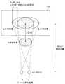
図1は、本発明の実施形態による表示装置100の外観を示した説明図である。なお、図1には、ユーザが着用するシャッタ眼鏡200も表示装置100と併せて示している。 FIG. 1 is an explanatory diagram showing an appearance of a
図1に示したように、表示装置100は、画像が表示される画像表示部110を備える。表示装置100は、左目用画像および右目用画像を画像表示部110に表示することにより、ユーザに立体視画像を知覚させることができる。また、この表示装置100は、「2.表示装置の構成」において詳細に説明するように、スピーカシステムを構成する各スピーカからの音声出力を制御する音声処理装置としての機能も有する。 As shown in FIG. 1, the
シャッタ眼鏡200は、例えば液晶シャッタからなる右目用画像透過部212及び左目用画像透過部214を含む。シャッタ眼鏡200は、表示装置100から送出される信号に応じて、右目用画像透過部212及び左目用画像透過部214の開閉動作を実行する。ユーザは、シャッタ眼鏡200の右目用画像透過部212及び左目用画像透過部214を通して、画像表示部110から発する光を見ることで、画像表示部110に表示される左目用画像および右目用画像を立体視画像として知覚することが出来る。 The
一方、通常の2D画像が画像表示部110に表示されている場合は、ユーザはそのまま画像表示部110から出射される光を見ることで、画像表示部110に表示される画像を通常の2D画像として知覚することができる。 On the other hand, when a normal 2D image is displayed on the
なお、図1では、音声処理装置の一例として表示装置100を示したが、音声処理装置はかかる例に限定されない。例えば、音声処理装置は、PC(Personal Computer)、家庭用映像処理装置(DVDレコーダ、ビデオデッキなど)、PDA(Personal Digital Assistants)、家庭用ゲーム機器、携帯電話、携帯用映像処理装置、携帯用ゲーム機器などの情報処理装置であってもよい。 In FIG. 1, the
また、本明細書においては、左目用画像が左目によって知覚され、右目用画像が右目によって知覚されるようにするためにシャッタ動作を利用する制御方式を説明するが、制御方式はかかる例に限定されない。例えば、左目用の偏光フィルタおよび右目用の偏光フィルタを用いることによっても同等な効果を得ることが可能である。 Further, in this specification, a control method using a shutter operation to allow the left eye image to be perceived by the left eye and the right eye image to be perceived by the right eye will be described. However, the control method is limited to such an example. Not. For example, the same effect can be obtained by using a polarizing filter for the left eye and a polarizing filter for the right eye.
<2.表示装置の構成>
以上、本発明の実施形態による表示装置100の概要を説明した。次に、図2を参照し、本発明の実施形態による表示装置100の構成を説明する。<2. Configuration of display device>
The overview of the
図2は、本発明の実施形態による表示装置100の構成を示した機能ブロック図である。図2に示したように、表示装置100は、画像表示部110と、映像信号制御部120と、シャッタ制御部130と、タイミング制御部140と、赤外線エミッタ150と、映像解析部160と、音声制御部170と、スピーカシステム180と、を備える。 FIG. 2 is a functional block diagram showing the configuration of the
画像表示部110は、上述したように画像の表示を行うための構成であり、外部から信号が印加されると、印加された信号に応じた画像を表示する。この画像表示部110は、図2に示したように、表示パネル112と、ゲートドライバ113と、データドライバ114と、バックライト115と、を含んで構成される。 The
表示パネル112は、外部からの信号の印加に応じて画像を表示するものである。表示パネル112は、複数の走査線に対する順次走査により画像を表示する。表示パネル112は、ガラス等の透明板の間に所定の配向状態を有する液晶分子が封入されている。表示パネル112の駆動方式は、TN(Twisted Nematic)方式、VA(Virtical Alignment)方式、またはIPS(In−Place−Switching)方式であってもよい。本発明の実施形態による表示パネル112は、外部からの信号印加に応じ、右目用画像と左目用画像を所定のタイミングで交互に表示する。 The
ゲートドライバ113は、表示パネル112のゲートバスライン(図示せず)を駆動するためのドライバである。ゲートドライバ113にはタイミング制御部140から信号が伝送され、ゲートドライバ113はタイミング制御部140から伝送された信号に応じてゲートバスラインへ信号を出力する。 The
データドライバ114は、表示パネル112のデータ線(図示せず)に印加するための信号を生成するためのドライバである。データドライバ114にはタイミング制御部140から信号が伝送され、データドライバ114はタイミング制御部140から伝送された信号に応じてデータ線へ印加する信号を生成して出力する。 The
バックライト115は、ユーザ側から見て画像表示部110の一番奥に設けられるものである。画像表示部110に画像を表示する際には、バックライト115からは偏光されていない(無偏光の)白色光がユーザ側に位置する表示パネル112に出射される。バックライト115としては、例えば発光ダイオードを用いてもよいし、冷陰極管を用いてもよい。なお、図2では、バックライト115として面光源を示しているが、本発明においては光源の形態はかかる例に限定されない。例えば、表示パネル112の周辺部に光源を配置し、当該光源からの光を拡散板等で拡散することで表示パネル112に光を出射してもよい。また例えば、面光源の替わりに点光源と集光レンズを組み合わせてもよい。 The
映像信号制御部120は、左目用画像および右目用画像を表示するための3D映像信号が入力されると、左目用画像および右目用画像を画像表示部110において交互に表示するための映像信号を生成する。映像信号制御部120により生成された映像信号はタイミング制御部140に伝送される。 When the 3D video signal for displaying the left-eye image and the right-eye image is input, the video
シャッタ制御部130は、映像信号制御部120における信号処理に応じて生成される所定の信号の伝送を受け、当該信号に応じてシャッタ眼鏡200のシャッタ動作を制御するシャッタ制御信号を生成する。シャッタ眼鏡200では、シャッタ制御部130で生成され、赤外線エミッタ150から発せされるシャッタ制御信号に基づいて、右目用画像透過部212及び左目用画像透過部214の開閉動作を実行する。具体的には、表示パネル112に左目用画像が表示されている間には左目用画像透過部214が開かれ、表示パネル112に右目用画像が表示されている間には右目用画像透過部212が開かれるようにシャッタ動作が実行される。 The
タイミング制御部140は、映像信号制御部120から伝送される信号に応じて、ゲートドライバ113およびデータドライバ114の動作に用いられるパルス信号を生成する。タイミング制御部140でパルス信号を生成して、ゲートドライバ113およびデータドライバ114がタイミング制御部140で生成されたパルス信号を受けることで、映像信号制御部120から伝送される映像信号に応じた画像が表示パネル112に表示される。 The
映像解析部160は、3D映像信号に基づく立体視画像のユーザによる代表知覚位置を推定する推定部として機能する。この推定のために、映像解析部160には、3D映像信号、画像表示部110の画面サイズ、ユーザおよび画像表示部110間の視聴距離などの情報が供給される。なお、画像表示部110の画面サイズ、ユーザおよび画像表示部110間の視聴距離などの情報は、表示装置100に設定されていてもよいし、ユーザ操作により入力されてもよい。また、代表知覚位置の推定方法については、「2−1.代表知覚位置の推定」において詳細に説明する。 The
音声制御部170は、映像解析部160により推定された代表知覚位置に応じ、スピーカシステム180(音声出力装置)からの音声出力を制御する。具体的には、スピーカシステム180は、センタースピーカC、フロントスピーカL(前方音声出力装置)、フロントスピーカR(前方音声出力装置)、リアスピーカLs(後方音声出力装置)、およびリアスピーカRs(後方音声出力装置)を含み、音声制御部170は、これら各スピーカ用からの音声出力を制御する。この音声制御部170による音声制御については、「2−2.音声制御の具体例」において詳細に説明する。 The
以上、本発明の実施形態による表示装置100の構成を説明した。以下、映像解析部160による代表知覚位置の推定、および音声制御部170による音声制御についてより詳細に説明する。 The configuration of the
[2−1.代表知覚位置の推定]
(第1の例)
代表知覚位置の推定には、画像表示部110の1ピクセルあたりの大きさが用いられる。したがって、この1ピクセルあたりの大きさが未知である場合、映像解析部160は、画像表示部110の画面サイズ情報から1ピクセルあたりの大きさ(pixel_cm)を算出する。[2-1. Estimation of representative perceived position]
(First example)
The size per pixel of the
例えば、画面サイズ情報として、以下の値が既知である場合を考える。
TV_INCH:画像表示部110の大きさ[inch]
TV_WIDTH_PIXEL:有効画面(横)のピクセル数[pixel]
TV_HEIGHT_PIXEL:有効画面(縦)のピクセル数[pixel]For example, consider the case where the following values are known as screen size information.
TV_INCH: Size of the image display unit 110 [inch]
TV_WIDTH_PIXEL: Number of pixels in the effective screen (horizontal) [pixel]
TV_HEIGHT_PIXEL: Effective screen (vertical) pixel count [pixel]
この場合、図3に示した下記の値を画面サイズ情報から算出することができる。
tv_size_pixel:有効画面の大きさ[pixel]
tv_size:有効画面の大きさ[cm]
tv_width:有効画面の横幅[cm]
tv_height:有効画面の高さ[cm]In this case, the following values shown in FIG. 3 can be calculated from the screen size information.
tv_size_pixel: effective screen size [pixel]
tv_size: Size of effective screen [cm]
tv_width: width of effective screen [cm]
tv_height: effective screen height [cm]
例えば、tv_size_pixelおよびtv_sizeは、以下の数式に従って算出される。
tv_size_pixel
=sqrt(TV_WIDTH_PIXEL^2
+TV_HEIGHT_PIXEL^2)
tv_size=TV_INCH×2.54For example, tv_size_pixel and tv_size are calculated according to the following equations.
tv_size_pixel
= Sqrt (TV_WIDTH_PIXEL ^ 2
+ TV_HEIGHT_PIXEL ^ 2)
tv_size = TV_INCH × 2.54
さらに、1ピクセルあたりの大きさであるpixel_cmは、tv_size_pixelおよびtv_sizeから、以下の数式に従って算出される。
pixel_cm=tv_size/tv_size_pixelFurthermore, pixel_cm, which is the size per pixel, is calculated from tv_size_pixel and tv_size according to the following formula.
pixel_cm = tv_size / tv_size_pixel
具体例として、TV_INCHが40inchであり、TV_WIDTH_PIXELが1920pixelであり、TV_HEIGHT_PIXELが1080pixelである場合、各値は以下のように算出される。
tv_size_pixel=2202.9pixel
tv_size =101.6cm
pixel_cm =0.0461cm
As a specific example, when TV_INCH is 40 inches, TV_WIDTH_PIXEL is 1920 pixels, and TV_HEIGHT_PIXEL is 1080 pixels, each value is calculated as follows.
tv_size_pixel = 2202.9pixel
tv_size = 101.6cm
pixel_cm = 0.0461cm
映像解析部160は、上記のpixel_cm、左目用画像および右目用画像の差分に基づき、ユーザによる立体視画像の代表知覚位置を推定する。すなわち、映像解析部160は、ユーザによる立体視画像の代表知覚位置と画像表示部110との間の距離xを算出する。ここで、代表知覚位置は、立体視画像のうちで代表的な画像オブジェクト(部分)のユーザによる知覚位置であってもよい。以下、この画像オブジェクトの検出について図4を参照して簡単に説明した後、図5を参照して距離xの算出方法を説明する。 The
映像解析部160は、例えば、顔検出技術を用いることにより左目用画像および右目用画像に含まれる顔画像を画像オブジェクトとして検出する。その結果、1の顔画像のみが検出された場合、映像解析部160は、当該顔画像のユーザによる知覚位置を代表知覚位置として扱い、当該顔画像に関する距離xを以下に説明する方法により算出する。一方、図4に示したように複数の顔画像A〜Cが検出された場合、映像解析部160は、いずれかの顔画像を選択し、選択した顔画像に関する距離xを算出してもよい。または、映像解析部160は、顔画像A〜Cに関する距離x(A)〜x(C)を算出し、距離x(A)〜x(C)の平均値を距離xとして算出してもよい。 For example, the
図5は、左目用画像および右目用画像に含まれる画像オブジェクトの表示位置と立体視画像の知覚位置との関係を示した説明図である。映像解析部160は、図5に示したように、左目用画像に含まれる画像オブジェクトと、右目用画像に含まれるある画像オブジェクトの水平方向の表示位置の差分であるLR_DIFF_PIXEL(pixel)を、上記のpixel_cmを用いてcm単位の値に換算する(下記数式参照)。
lr_diff=LR_DIFF_PIXEL×pixel_cmFIG. 5 is an explanatory diagram showing the relationship between the display position of the image object included in the left-eye image and the right-eye image and the perceived position of the stereoscopic image. As shown in FIG. 5, the
lr_diff = LR_DIFF_PIXEL × pixel_cm
ここで、画像表示部110とユーザ間の距離D(cm)およびユーザの目の間隔E(cm)が既知である場合、映像解析部160は、画像オブジェクトのユーザによる知覚位置の画像表示部110からの距離x(cm)を、以下の数式に従って算出することができる。
x=lr_diff×D/(E+lr_diff)Here, when the distance D (cm) between the
x = lr_diff × D / (E + lr_diff)
具体例として、LR_DIFF_PIXELが10pixelであり、pixel_cmが0.0461cmであり、距離Dが250cmであり、間隔Eが6cmである場合、lr_diffおよび距離xは以下の値となる。なお、ユーザによる画像オブジェクトの知覚位置が画像表示部110の裏側である場合、距離xは負の値となる。
lr_diff=0.4612cm
x=17.845cmAs a specific example, when LR_DIFF_PIXEL is 10 pixels, pixel_cm is 0.0461 cm, distance D is 250 cm, and interval E is 6 cm, lr_diff and distance x have the following values. When the perceived position of the image object by the user is on the back side of the
lr_diff = 0.612cm
x = 17.845 cm
(第2の例)
第1の例においては、代表知覚位置が、立体視画像のうちで代表的な画像オブジェクト(部分)のユーザによる知覚位置である例を説明したが、代表知覚位置はかかる例に限定されない。例えば、代表知覚位置は、以下に説明するように、立体視画像を構成する各領域のユーザによる知覚位置のうちで支配的であると考えられる位置であってもよい。(Second example)
In the first example, an example in which the representative perceived position is a perceived position by a user of a representative image object (part) in the stereoscopic image has been described, but the representative perceived position is not limited to this example. For example, as described below, the representative perceived position may be a position that is considered to be dominant among the perceived positions by the user of each region constituting the stereoscopic image.
このような代表知覚位置の推定のために、第2の例においては、左目用画像および右目用画像を分割して複数の領域を定義し、各領域のユーザによる知覚位置と画像表示部110との距離を推定し、各領域に関して推定された距離の分布に基づいて距離xを算出する。以下、図6および図7を参照してより詳細に説明する。 In order to estimate such a representative perceived position, in the second example, the left-eye image and the right-eye image are divided to define a plurality of areas, and the perceived position of each area by the user and the
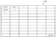
図6は、画像分割の一例を示した説明図である。図6に示したように、映像解析部160は、左目用画像および右目用画像においてエリア0〜エリアNを定める。なお、各エリアの形状およびサイズは特に限定されず、各エリアは例えば10×10pixelで構成されてもよい。 FIG. 6 is an explanatory diagram showing an example of image division. As shown in FIG. 6, the
そして、映像解析部160は、エリアごとに、当該エリア内の画像のユーザによる知覚位置と画像表示部110との距離xm(0≦m≦N)を第1の例において説明した方法に準じて算出する。例えばエリア数が10である場合、映像解析部160は、図7に示したように、エリア0〜エリア9ごとに距離x0〜x9を算出する。 Then, for each area, the
さらに、映像解析部160は、エリアごとに算出された距離xmの分布に基づいて距離xを特定する。例えば、映像解析部160は、エリアごとに算出された距離xmのうちで、最も多い値を距離xとして扱ってもよい。この方法によれば、図7に示した例では、エリアごとに算出された距離x0〜x9のうちで最も多い値である4cmが距離xとして扱われる。 Furthermore, the
または、映像解析部160は、所定の値幅ごとに当該値幅に含まれる距離xmの数を集計し、最も距離xmを多く含む値幅に基づいて距離xを特定してもよい。例えば、0〜5cm、5〜10cmというように、5cm幅ごとの値幅に該当する距離x(エリア)の数を集計する場合、図7に示した例では、20〜25cmの値幅に含まれる距離xmの数が最も多くなる。この場合、映像解析部160は、当該値幅の最小値である20cmを距離xとして扱ってもよいし、当該値幅に含まれる距離xmの平均値を距離xとして扱ってもよい。 Alternatively, the
[2−2.音声制御の具体例]
音声制御部170は、映像解析部160により上記のようにして得られた距離xに基づき、スピーカシステム180からの音声出力を制御する。以下、図8〜図13を参照し、音声制御部170による音声出力の制御について具体的に説明する。[2-2. Specific example of voice control]
The
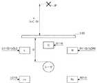
(x=0である場合)
映像解析部160により得られた距離xが「0」である場合、すなわち、ユーザによる立体視画像の知覚位置Pが画像表示部110の配置位置(基準面の一例)と一致する場合、音声制御部170は、各スピーカ用の音声信号を対応するスピーカからそのまま出力させる。(When x = 0)
When the distance x obtained by the
具体的には、音声制御部170は、図8に示したように、センタースピーカC用の音声信号C1をセンタースピーカCに供給し、フロントスピーカL用の音声信号L1をフロントスピーカLに供給し、フロントスピーカR用の音声信号R1をフロントスピーカRに供給する。同様に、音声制御部170は、リアスピーカLs用の音声信号L2をリアスピーカLsに供給し、リアスピーカRs用の音声信号R2をリアスピーカRsに供給する。 Specifically, the
(x>0である場合)
続いて、図9を参照し、映像解析部160により得られた距離xが「0」より大きい場合、すなわち、ユーザによる立体視画像の知覚位置Pが画像表示部110よりユーザ側である場合の音声制御部170による音声制御について説明する。(When x> 0)
Subsequently, referring to FIG. 9, when the distance x obtained by the
図9は、ユーザによる立体視画像の知覚位置Pが画像表示部110よりユーザ側である場合の音声制御部170による音声制御を示した説明図である。この場合、音声制御部170は、本来のフロントスピーカL用の音声信号L1を、距離xに応じた音量比率でフロントスピーカLおよびリアスピーカLsに供給する。より具体的には、音声制御部170は、距離xが大きくなるほど高い比率で音声信号L1をリアスピーカLsに供給する。 FIG. 9 is an explanatory diagram showing audio control by the
同様に、音声制御部170は、本来のフロントスピーカR用の音声信号R1を、距離xに応じた音量比率でフロントスピーカRおよびリアスピーカRsに供給する。より具体的には、音声制御部170は、距離xが大きくなるほど高い比率で音声信号R1をリアスピーカRsに供給する。 Similarly, the
また、音声制御部170は、距離xが大きくなるにつれて、リアスピーカLsに供給する本来のリアスピーカ用の音声信号L2を小さくし、リアスピーカRsに供給する本来のリアスピーカ用の音声信号R2を小さくする。 Further, as the distance x increases, the
一例として、音声制御部170は、下記数式により表現されるC1’、L1’、R1’、L2’、およびR2’を、各々センタースピーカC、フロントスピーカL、フロントスピーカR、リアスピーカLs、およびリアスピーカRsに供給してもよい。なお、下記数式におけるC1は、L1、R1、L2、およびR2は、対応するスピーカ用の本来の音声信号である。 As an example, the
C1’=(1−x/D)C1
L1’=(1−x/D)L1
R1’=(1−x/D)R1
L2’=(1−x/D)L2+(x/D)L1+(1−x/D)C1/2
R2’=(1−x/D)R2+(x/D)R1+(1−x/D)C1/2C1 ′ = (1−x / D) C1
L1 ′ = (1−x / D) L1
R1 ′ = (1−x / D) R1
L2 '= (1-x / D) L2 + (x / D) L1 + (1-x / D) C1 / 2
R2 '= (1-x / D) R2 + (x / D) R1 + (1-x / D) C1 / 2
(x=Dである場合)
なお、図10に示したように、映像解析部160により得られた距離xがユーザによる視聴距離Dと等しい場合、音声制御部170は上記数式に従い、下記数式により表現されるC1’、L1’、R1’、L2’、およびR2’を対応するスピーカに供給する。(When x = D)
As shown in FIG. 10, when the distance x obtained by the
C1’=0
L1’=0
R1’=0
L2’=L1+C1/2
R2’=R1+C1/2C1 '= 0
L1 '= 0
R1 ′ = 0
L2 ′ = L1 + C1 / 2
R2 '= R1 + C1 / 2
(−D<x<0である場合)
次に、図11を参照し、映像解析部160により得られた距離xに関して「−D<x<0」が満たされる場合、すなわち、画像表示部110がユーザによる立体視画像の知覚位置Pよりユーザ側であり、xの絶対値がD未満である場合の音声制御について説明する。(When -D <x <0)
Next, referring to FIG. 11, when “−D <x <0” is satisfied with respect to the distance x obtained by the
図11は、画像表示部110がユーザによる立体視画像の知覚位置Pよりユーザ側である場合の音声制御部170による音声制御を示した説明図である。この場合、音声制御部170は、本来のリアスピーカLs用の音声信号L2を、距離xに応じた音量比率でフロントスピーカLおよびリアスピーカLsに供給する。より具体的には、音声制御部170は、距離xの絶対値が大きくなるほど高い比率で音声信号L2をフロントスピーカLに供給する。 FIG. 11 is an explanatory diagram showing audio control by the
同様に、音声制御部170は、本来のリアスピーカRs用の音声信号R2を、距離xに応じた音量比率でフロントスピーカRおよびリアスピーカRsに供給する。より具体的には、音声制御部170は、距離xの絶対値が大きくなるほど高い比率で音声信号R2をフロントスピーカRに供給する。 Similarly, the
また、音声制御部170は、距離xの絶対値が大きくなるにつれて、フロントスピーカLに供給する音声信号L1を小さくし、フロントスピーカRに供給する音声信号R1を小さくする。 Further, the
一例として、音声制御部170は、下記数式により表現されるC1’、L1’、R1’、L2’、およびR2’を、各々センタースピーカC、フロントスピーカL、フロントスピーカR、リアスピーカLs、およびリアスピーカRsに供給してもよい。 As an example, the
C1’=(1−│x│/D)C1
L1’=(1−│x│/D)L1+(│x│/D)L2
R1’=(1−│x│/D)R1+(│x│/D)R2
L2’=(1−│x│/D)L2
R2’=(1−│x│/D)R2C1 ′ = (1− | x | / D) C1
L1 ′ = (1− | x | / D) L1 + (| x | / D) L2
R1 ′ = (1− | x | / D) R1 + (| x | / D) R2
L2 ′ = (1− | x | / D) L2
R2 '= (1- | x | / D) R2
(−D=xである場合)
なお、図12に示したように、映像解析部160により得られた距離xの絶対値がユーザによる視聴距離Dと等しい場合、音声制御部170は上記数式に従い、下記数式により表現されるC1’、L1’、R1’、L2’、およびR2’を対応するスピーカに供給する。(When -D = x)
As shown in FIG. 12, when the absolute value of the distance x obtained by the
C1’=0
L1’=L2
R1’=R2
L2’=0
R2’=0C1 '= 0
L1 '= L2
R1 ′ = R2
L2 '= 0
R2 ′ = 0
(x<−Dである場合)
続いて、図13を参照し、映像解析部160により得られた距離xに関して「x<−D」が満たされる場合、すなわち、画像表示部110がユーザによる立体視画像の知覚位置Pよりユーザ側であり、xの絶対値がDを上回る場合の音声制御について説明する。(When x <−D)
Subsequently, referring to FIG. 13, when “x <−D” is satisfied with respect to the distance x obtained by the
図13は、画像表示部110がユーザによる立体視画像の知覚位置Pよりユーザ側である場合の音声制御部170による音声制御を示した説明図である。この場合、音声制御部170は、本来のリアスピーカLs用の音声信号L2を、距離xに応じた大きさでフロントスピーカLに供給する。より具体的には、音声制御部170は、距離xの絶対値が大きくなるほどフロントロントスピーカLに供給する音声信号L2を小さくする。 FIG. 13 is an explanatory diagram showing audio control by the
同様に、音声制御部170は、本来のリアスピーカRs用の音声信号R2を、距離xに応じた大きさでフロントスピーカRに供給する。より具体的には、音声制御部170は、距離xの絶対値が大きくなるほどフロントロントスピーカRに供給する音声信号R2を小さくする。 Similarly, the
一例として、音声制御部170は、下記数式により表現されるC1’、L1’、R1’、L2’、およびR2’を、各々センタースピーカC、フロントスピーカL、フロントスピーカR、リアスピーカLs、およびリアスピーカRsに供給してもよい。 As an example, the
C1’=0
L1’=(D/│x│)L2
R1’=(D/│x│)R2
L2’=0
R2’=0C1 '= 0
L1 ′ = (D / | x |) L2
R1 ′ = (D / | x |) R2
L2 '= 0
R2 ′ = 0
以上説明したように、本発明の実施形態による表示装置100は、左目用画像および右目用画像に基づく立体視画像のユーザによる代表知覚位置に応じ、各スピーカからの音声出力を制御することができる。 As described above, the
<3.表示装置の動作>
次に、図14を参照し、本発明の実施形態による表示装置100の動作を簡潔にまとめる。<3. Operation of display device>
Next, the operation of the
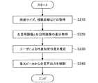
図14は、本発明の実施形態による表示装置100の動作を示したフローチャートである。図14に示したように、まず、表示装置100の映像解析部160は、表示装置100の画面サイズ、およびユーザによる視聴距離などの情報を取得する(S210)。また、映像解析部160は、3D映像信号の入力に基づき、左目用画像と右目用画像の差分を取得する(S220)。 FIG. 14 is a flowchart illustrating the operation of the
そして、映像解析部160は、S210において取得した情報、および、左目用画像と右目用画像の差分に基づき、立体視画像のユーザによる代表知覚位置を推定する(S230)。すなわち、映像解析部160は、ユーザによる立体視画像の代表知覚位置と画像表示部110との間の距離xを算出する。なお、距離xは、「2−1.代表知覚位置の推定」において説明したように、多様な方法により算出することが可能である。その後、音声制御部170は、映像解析部160により算出された距離xに応じ、スピーカシステム180を構成する各スピーカからの音声出力を制御する(S240)。 Then, the
<4.まとめ>
以上説明したように、本発明の実施形態による表示装置100は、左目用画像および右目用画像に基づく立体視画像のユーザによる代表知覚位置に応じ、各スピーカからの音声出力を制御することができる。その結果、左目用画像および右目用画像からなる3D画像と音声信号の連携をより強調することが可能となる。<4. Summary>
As described above, the
例えば、表示装置100は、歌舞伎や演劇などのコンテンツに関し、舞台のユーザによる知覚位置が画像表示部110の後方である場合には、本来のリアスピーカ用の音声信号をフロントスピーカから出力させる。かかる構成により、舞台全体を遠くから眺めている感覚をより強くユーザに与えることが可能となる。また、表示装置100は、オーケストラ演奏などのコンテンツに関し、オーケストラのユーザによる知覚位置が画像表示部110よりユーザ側である場合には、本来のフロントスピーカ用の音声信号をリアスピーカから出力させる。かかる構成により、オーケストラの一員として演奏現場にいるような臨場感をより強くユーザに与えることが可能となる。 For example, when the perceived position by the user on the stage is behind the
なお、添付図面を参照しながら本発明の好適な実施形態について詳細に説明したが、本発明はかかる例に限定されない。本発明の属する技術の分野における通常の知識を有する者であれば、特許請求の範囲に記載された技術的思想の範疇内において、各種の変更例または修正例に想到し得ることは明らかであり、これらについても、当然に本発明の技術的範囲に属するものと了解される。 Although the preferred embodiments of the present invention have been described in detail with reference to the accompanying drawings, the present invention is not limited to such examples. It is obvious that a person having ordinary knowledge in the technical field to which the present invention pertains can come up with various changes or modifications within the scope of the technical idea described in the claims. Of course, it is understood that these also belong to the technical scope of the present invention.
例えば、上記実施形態では、立体視画像のうちで代表的な画像オブジェクトを顔検出技術により検出する例を説明したが、本発明はかかる例に限定されない。顔画像でなくても、動きを有する被写体は代表的な画像オブジェクトであると考えられる。そこで、表示装置100は、動きを有する被写体を立体視画像のうちで代表的な画像オブジェクトとして検出するために、一例として以下の処理を行ってもよい。
(ステップ1)
表示装置100は、各フレームに基づき、各フレームの撮像時における撮像装置の動きを検出する。撮像装置の動きには、撮像装置の位置の移動や、撮像装置による撮像方向の変化などが含まれる。この撮像装置の動きは、例えば、連続する2のフレームの差分に基づいて検出することができる。より具体的には、表示装置100は、フレームL−1を構成するブロックごとに、フレームLに対する動き予測を行い、ブロックごとの動きベクトルを得る。そして、表示装置100は、全ブロックの動きベクトルから、支配的な方向に対して大きく異なる動きベクトルを除き、他の動きベクトルから撮像装置の動きベクトルを検出する。
(ステップ2)
表示装置100は、フレームL−1を、ステップ1において検出した撮像装置の動きベクトルをキャンセルするようにフレームL−1を変換する。例えば、ステップ1において検出された撮像装置の動きベクトルの方向がQ、大きさがRであった場合、フレームL−1内の画像を、−Q方向に大きさRだけ移動させる。
(ステップ3)
表示装置100は、フレームLと、ステップ2による変換後のフレームL−1との差分画像を生成する。ここで、静止している物体であっても、撮像装置の動きにより、フレームLとフレームL−1における存在位置は異なる。しかし、上記のように、変換後のフレームL−1においては撮像装置の動きがキャンセルされているため、静止している物体のフレームLおよび変換後のフレームL−1における存在位置はほぼ一致すると考えられる。このため、フレームLと変換後のフレームL−1との差分画像においては、主に動きを有する被写体がフレーム間の差分として現れる。
(ステップ4)
表示装置100は、ステップ3で生成した差分画像から、動きを有する被写体を検出する。表示装置100は、このようにして動きを有する被写体を立体視画像のうちで代表的な画像オブジェクトとして検出できるので、動きを有する被写体のユーザによる知覚位置をユーザによる代表知覚位置として算出することできる。かかる構成により、表示装置100は、動きを有する被写体として例えばサーキットの立体視画像中でレーシングカーを検出し、ユーザによるレーシングカーの知覚位置に応じて音声制御を行うことが可能である。For example, in the above-described embodiment, an example in which a representative image object is detected from the stereoscopic image by the face detection technique has been described, but the present invention is not limited to such an example. Even if it is not a face image, a moving subject is considered to be a representative image object. Therefore, the
(Step 1)
The
(Step 2)
The
(Step 3)
The
(Step 4)
The
または、表示装置100は、撮像装置により追跡して撮像された被写体(追っかけ撮りされた被写体)を立体視画像のうちで代表的な画像オブジェクトとして検出し、ユーザによる当該被写体の知覚位置に応じて音声制御を行ってもよい。撮像装置により追跡して撮像された被写体を検出するための方法の一例を以下に説明する。
(ステップ1)
表示装置100は、各フレームに基づき、各フレームの撮像時における撮像装置の動きを検出する。
(ステップ2)
表示装置100は、ステップ1で検出した撮像装置の動き量が閾値を上回った区間を撮像装置が動いていた区間として判断する。
(ステップ3)
表示装置100は、撮像装置が動いていた区間において、所定長さ以上の区間にわたって検出された被写体を、追跡して撮像された被写体として検出する。Alternatively, the
(Step 1)
The
(Step 2)
The
(Step 3)
The
また、上記では、各スピーカからの音声制御として、各スピーカから出力させる音声信号の音量を制御する例を説明したが、本発明はかかる例に限定されない。例えば、音量制御に代えて、または音量制御と共に、各スピーカから出力させる音声信号の位相を制御することも本発明の技術的範囲に属する。 Moreover, although the example which controls the sound volume of the audio | voice signal output from each speaker as the audio | voice control from each speaker was demonstrated above, this invention is not limited to this example. For example, it is also within the technical scope of the present invention to control the phase of an audio signal output from each speaker instead of or together with volume control.
また、本明細書の表示装置100の処理における各ステップは、必ずしもフローチャートとして記載された順序に沿って時系列に処理する必要はない。例えば、表示装置100の処理における各ステップは、フローチャートとして記載した順序と異なる順序で処理されても、並列的に処理されてもよい。また、表示装置100に内蔵されるCPU、ROMおよびRAMなどのハードウェアを、上述した表示装置100の各構成と同等の機能を発揮させるためのコンピュータプログラムも作成可能である。また、該コンピュータプログラムを記憶させた記憶媒体も提供される。 Further, each step in the processing of the
100 表示装置
110 画面表示部
120 映像信号制御部
130 シャッタ制御部
140 タイミング制御部
150 赤外線エミッタ
160 映像解析部
170 音声制御部
180 スピーカシステム
DESCRIPTION OF
Claims (11)
Translated fromJapanese前記推定部により推定された前記代表知覚位置に応じ、音声出力装置による音声出力を制御する音声制御部と;
を備え、
前記音声出力装置は、前方音声出力装置、および、前記前方音声出力装置より前記表示装置と離隔する位置に配置される後方音声出力装置を含み、
前記音声制御部は、前記代表知覚位置と基準面との距離に応じ、前記前方音声出力装置および前記後方音声出力装置による音声出力を制御し、
前記音声制御部は、前記代表知覚位置が前記基準面と一致する場合、前記前方音声出力装置には前記前方音声出力装置用の第1の音声信号を供給し、前記後方音声出力装置には前記後方音声出力装置用の第2の音声信号を供給し、
前記音声制御部は、前記代表知覚位置が前記基準面よりユーザ側である場合、前記第1の音声信号を、前記代表知覚位置と前記基準面との距離に応じた比率で前記前方音声出力装置および前記後方音声出力装置に供給する、音声処理装置。An estimation unit that estimates a representative perceived position of a stereoscopic image based on the left-eye image and the right-eye image from a difference between the left-eye image and the right-eye image displayed on the display device;
A voice control unit that controls voice output by a voice output device in accordance with the representative perceived position estimated by the estimation unit;
With
The audio output device includes a front audio output device, and a rear audio output device arranged at a position separated from the display device from the front audio output device,
The voice control unit controls voice output by the front voice output device and the rear voice output device according to a distance between the representative perceived position and a reference plane,
The audio control unit supplies a first audio signal for the front audio output device to the front audio output device when the representative perceived position coincides with the reference plane, and supplies the first audio signal to the rear audio output device. Providing a second audio signal for the rear audio output device;
When the representative perceived position is closer to the user than the reference plane, the voice control unit outputs the first voice signal at a ratio corresponding to a distance between the representative perceived position and the reference plane. And an audio processing devicefor supplying to the rear audio output device.
前記推定部により推定された前記代表知覚位置に応じ、音声出力装置による音声出力を制御する音声制御部と; A voice control unit that controls voice output by a voice output device in accordance with the representative perceived position estimated by the estimation unit;
を備え、With
前記音声出力装置は、前方音声出力装置、および、前記前方音声出力装置より前記表示装置と離隔する位置に配置される後方音声出力装置を含み、 The audio output device includes a front audio output device, and a rear audio output device arranged at a position separated from the display device from the front audio output device,
前記音声制御部は、前記代表知覚位置と基準面との距離に応じ、前記前方音声出力装置および前記後方音声出力装置による音声出力を制御し、 The voice control unit controls voice output by the front voice output device and the rear voice output device according to a distance between the representative perceived position and a reference plane,
前記音声制御部は、前記代表知覚位置が前記基準面と一致する場合、前記前方音声出力装置には前記前方音声出力装置用の第1の音声信号を供給し、前記後方音声出力装置には前記後方音声出力装置用の第2の音声信号を供給し、 The audio control unit supplies a first audio signal for the front audio output device to the front audio output device when the representative perceived position coincides with the reference plane, and supplies the first audio signal to the rear audio output device. Providing a second audio signal for the rear audio output device;
前記音声制御部は、前記基準面が前記代表知覚位置よりユーザ側である場合、前記第2の音声信号を、前記代表知覚位置と前記基準面との距離に応じた比率で前記前方音声出力装置および前記後方音声出力装置に供給する、音声処理装置 When the reference plane is closer to the user than the representative perceived position, the voice control unit is configured to output the second voice signal at a ratio corresponding to a distance between the representative perceived position and the reference plane. And an audio processing apparatus for supplying to the rear audio output apparatus
前記推定部により推定された前記代表知覚位置に応じ、音声出力装置による音声出力を制御する音声制御部と; A voice control unit that controls voice output by a voice output device in accordance with the representative perceived position estimated by the estimation unit;
を備え、With
前記推定部は、前記左目用画像および前記右目用画像に含まれる1または2以上の画像オブジェクトのユーザによる知覚位置を推定し、前記1または2以上の画像オブジェクトの知覚位置に基づいて前記代表知覚位置を推定する、請求項1に記載の音声処理装置。 The estimation unit estimates a perceived position by a user of one or more image objects included in the left-eye image and the right-eye image, and the representative perception is based on a perceived position of the one or more image objects. The speech processing apparatus according to claim 1, wherein the position is estimated.
前記代表知覚位置に応じ、音声出力装置による音声出力を制御するステップと;
を含み、
前記音声出力装置は、前方音声出力装置、および、前記前方音声出力装置より前記表示装置と離隔する位置に配置される後方音声出力装置を含み、
前記音声出力を制御するステップは、
前記代表知覚位置と基準面との距離に応じ、前記前方音声出力装置および前記後方音声出力装置による音声出力を制御し、
前記代表知覚位置が前記基準面と一致する場合、前記前方音声出力装置には前記前方音声出力装置用の第1の音声信号を供給し、前記後方音声出力装置には前記後方音声出力装置用の第2の音声信号を供給し、
前記代表知覚位置が前記基準面よりユーザ側である場合、前記第1の音声信号を、前記代表知覚位置と前記基準面との距離に応じた比率で前記前方音声出力装置および前記後方音声出力装置に供給する、ことを含む、音声処理方法。Estimating a representative perceived position by a user of a stereoscopic image based on the left-eye image and the right-eye image from the difference between the left-eye image and the right-eye image displayed on the display device;
Controlling audio output by the audio output device in accordance with the representative perceived position;
Including
The audio output device includes a front audio output device, and a rear audio output device arranged at a position separated from the display device from the front audio output device,
The step of controlling the audio output includes
According to the distance between the representative perceived position and the reference plane, the audio output by the front audio output device and the rear audio output device is controlled,
When the representative perceived position coincides with the reference plane, the front audio output device is supplied with the first audio signal for the front audio output device, and the rear audio output device is supplied with the signal for the rear audio output device. Providing a second audio signal;
When the representative perceived position is closer to the user than the reference plane, the front audio output apparatus and the rear audio output apparatus are configured to output the first audio signal at a ratio corresponding to the distance between the representative perceived position and the reference plane. A voice processing methodcomprising:
表示装置に表示される左目用画像と右目用画像の差分から、前記左目用画像および前記右目用画像に基づく立体視画像のユーザによる代表知覚位置を推定する推定部と;
前記推定部により推定された前記代表知覚位置に応じ、音声出力装置による音声出力を制御する音声制御部と;
を備え、
前記音声出力装置は、前方音声出力装置、および、前記前方音声出力装置より前記表示装置と離隔する位置に配置される後方音声出力装置を含み、
前記音声制御部は、前記代表知覚位置と基準面との距離に応じ、前記前方音声出力装置および前記後方音声出力装置による音声出力を制御し、
前記音声制御部は、前記代表知覚位置が前記基準面と一致する場合、前記前方音声出力装置には前記前方音声出力装置用の第1の音声信号を供給し、前記後方音声出力装置には前記後方音声出力装置用の第2の音声信号を供給し、
前記音声制御部は、前記代表知覚位置が前記基準面よりユーザ側である場合、前記第1の音声信号を、前記代表知覚位置と前記基準面との距離に応じた比率で前記前方音声出力装置および前記後方音声出力装置に供給する、音声処理装置、として機能させるための、プログラム。
Computer
An estimation unit that estimates a representative perceived position of a stereoscopic image based on the left-eye image and the right-eye image from a difference between the left-eye image and the right-eye image displayed on the display device;
A voice control unit that controls voice output by a voice output device in accordance with the representative perceived position estimated by the estimation unit;
With
The audio output device includes a front audio output device, and a rear audio output device arranged at a position separated from the display device from the front audio output device,
The voice control unit controls voice output by the front voice output device and the rear voice output device according to a distance between the representative perceived position and a reference plane,
The audio control unit supplies a first audio signal for the front audio output device to the front audio output device when the representative perceived position coincides with the reference plane, and supplies the first audio signal to the rear audio output device. Providing a second audio signal for the rear audio output device;
When the representative perceived position is closer to the user than the reference plane, the voice control unit outputs the first voice signal at a ratio corresponding to a distance between the representative perceived position and the reference plane. And a program for functioning as a sound processingdevice to be supplied to the rear sound output device .
Priority Applications (3)
| Application Number | Priority Date | Filing Date | Title |
|---|---|---|---|
| JP2010149365AJP5573426B2 (en) | 2010-06-30 | 2010-06-30 | Audio processing apparatus, audio processing method, and program |
| US13/161,604US9351092B2 (en) | 2010-06-30 | 2011-06-16 | Audio processing device, audio processing method, and program |
| CN2011101765577ACN102316343A (en) | 2010-06-30 | 2011-06-23 | Audio processing equipment, audio-frequency processing method and program |
Applications Claiming Priority (1)
| Application Number | Priority Date | Filing Date | Title |
|---|---|---|---|
| JP2010149365AJP5573426B2 (en) | 2010-06-30 | 2010-06-30 | Audio processing apparatus, audio processing method, and program |
Publications (2)
| Publication Number | Publication Date |
|---|---|
| JP2012015728A JP2012015728A (en) | 2012-01-19 |
| JP5573426B2true JP5573426B2 (en) | 2014-08-20 |
Family
ID=45399736
Family Applications (1)
| Application Number | Title | Priority Date | Filing Date |
|---|---|---|---|
| JP2010149365AExpired - Fee RelatedJP5573426B2 (en) | 2010-06-30 | 2010-06-30 | Audio processing apparatus, audio processing method, and program |
Country Status (3)
| Country | Link |
|---|---|
| US (1) | US9351092B2 (en) |
| JP (1) | JP5573426B2 (en) |
| CN (1) | CN102316343A (en) |
Families Citing this family (4)
| Publication number | Priority date | Publication date | Assignee | Title |
|---|---|---|---|---|
| CN103893971B (en)* | 2012-12-25 | 2015-05-27 | 腾讯科技(深圳)有限公司 | Game sound effect generating method and client |
| CN103905810B (en)* | 2014-03-17 | 2017-12-12 | 北京智谷睿拓技术服务有限公司 | Multi-media processing method and multimedia processing apparatus |
| EP3016401A1 (en)* | 2014-10-30 | 2016-05-04 | Patents Factory Ltd. Sp. z o.o. | A method and system for synchronizing playback of audio and video in a three-dimensional space |
| CN115575743B (en)* | 2022-09-29 | 2025-05-23 | 东风汽车集团股份有限公司 | Electromagnetic compatibility testing system and method for vehicle-mounted audio system |
Family Cites Families (44)
| Publication number | Priority date | Publication date | Assignee | Title |
|---|---|---|---|---|
| US4706117A (en)* | 1984-06-01 | 1987-11-10 | Arnold Schoolman | Stereo laser disc viewing system |
| JP3309443B2 (en)* | 1992-10-28 | 2002-07-29 | ソニー株式会社 | Glasses-type viewer |
| US5422653A (en)* | 1993-01-07 | 1995-06-06 | Maguire, Jr.; Francis J. | Passive virtual reality |
| JPH06301390A (en)* | 1993-04-12 | 1994-10-28 | Sanyo Electric Co Ltd | Stereoscopic sound image controller |
| US5579026A (en)* | 1993-05-14 | 1996-11-26 | Olympus Optical Co., Ltd. | Image display apparatus of head mounted type |
| JPH08140200A (en)* | 1994-11-10 | 1996-05-31 | Sanyo Electric Co Ltd | Three-dimensional sound image controller |
| US5714997A (en)* | 1995-01-06 | 1998-02-03 | Anderson; David P. | Virtual reality television system |
| US6141034A (en)* | 1995-12-15 | 2000-10-31 | Immersive Media Co. | Immersive imaging method and apparatus |
| JPH1063470A (en)* | 1996-06-12 | 1998-03-06 | Nintendo Co Ltd | Souond generating device interlocking with image display |
| GB9800397D0 (en)* | 1998-01-09 | 1998-03-04 | Philips Electronics Nv | Virtual environment viewpoint control |
| GB9928682D0 (en)* | 1999-12-06 | 2000-02-02 | Electrotextiles Comp Ltd | Input apparatus and a method of generating control signals |
| US6543899B2 (en)* | 2000-12-05 | 2003-04-08 | Eastman Kodak Company | Auto-stereoscopic viewing system using mounted projection |
| US6961458B2 (en)* | 2001-04-27 | 2005-11-01 | International Business Machines Corporation | Method and apparatus for presenting 3-dimensional objects to visually impaired users |
| US6752498B2 (en)* | 2001-05-14 | 2004-06-22 | Eastman Kodak Company | Adaptive autostereoscopic display system |
| US6963671B2 (en) | 2002-04-17 | 2005-11-08 | Mitsubishi Electric Research Labs, Inc. | Method for determining distances to a surface from a range image |
| JP2005141102A (en)* | 2003-11-07 | 2005-06-02 | Pioneer Electronic Corp | Stereoscopic two-dimensional image display device and its method |
| JP4069855B2 (en)* | 2003-11-27 | 2008-04-02 | ソニー株式会社 | Image processing apparatus and method |
| US7563168B2 (en)* | 2004-02-13 | 2009-07-21 | Texas Instruments Incorporated | Audio effect rendering based on graphic polygons |
| US7492915B2 (en)* | 2004-02-13 | 2009-02-17 | Texas Instruments Incorporated | Dynamic sound source and listener position based audio rendering |
| CN101006110A (en)* | 2004-04-05 | 2007-07-25 | 迈克尔·A.·韦塞利 | Horizontal Perspective Interactive Simulator |
| US20050219240A1 (en)* | 2004-04-05 | 2005-10-06 | Vesely Michael A | Horizontal perspective hands-on simulator |
| JP2008507006A (en)* | 2004-06-01 | 2008-03-06 | マイケル エー. ベセリー | Horizontal perspective simulator |
| JP2006128816A (en)* | 2004-10-26 | 2006-05-18 | Victor Co Of Japan Ltd | Recording program and reproducing program corresponding to stereoscopic video and stereoscopic audio, recording apparatus and reproducing apparatus, and recording medium |
| JP2006128818A (en)* | 2004-10-26 | 2006-05-18 | Victor Co Of Japan Ltd | Recording program and reproducing program corresponding to stereoscopic video and 3d audio, recording apparatus, reproducing apparatus and recording medium |
| JP2006139827A (en)* | 2004-11-10 | 2006-06-01 | Victor Co Of Japan Ltd | Device for recording three-dimensional sound field information, and program |
| JP2006140618A (en)* | 2004-11-10 | 2006-06-01 | Victor Co Of Japan Ltd | Three-dimensional video information recording device and program |
| JP2006148542A (en)* | 2004-11-19 | 2006-06-08 | Victor Co Of Japan Ltd | Three-dimensional sound field information reproducing device and program |
| JP2006191357A (en)* | 2005-01-06 | 2006-07-20 | Victor Co Of Japan Ltd | Reproduction device and reproduction program |
| JP2006245680A (en)* | 2005-02-28 | 2006-09-14 | Victor Co Of Japan Ltd | Video audio reproduction method and video audio reproduction apparatus |
| JP2006179174A (en)* | 2006-01-23 | 2006-07-06 | Victor Co Of Japan Ltd | Recording method of video signal, video signal recording apparatus and recording medium of video signal |
| JP4867367B2 (en)* | 2006-01-30 | 2012-02-01 | ヤマハ株式会社 | Stereo sound reproduction device |
| US8248462B2 (en)* | 2006-12-15 | 2012-08-21 | The Board Of Trustees Of The University Of Illinois | Dynamic parallax barrier autosteroscopic display system and method |
| US8269822B2 (en)* | 2007-04-03 | 2012-09-18 | Sony Computer Entertainment America, LLC | Display viewing system and methods for optimizing display view based on active tracking |
| KR101362647B1 (en)* | 2007-09-07 | 2014-02-12 | 삼성전자주식회사 | System and method for generating and palying three dimensional image file including two dimensional image |
| US8786675B2 (en)* | 2008-01-23 | 2014-07-22 | Michael F. Deering | Systems using eye mounted displays |
| CN101593541B (en)* | 2008-05-28 | 2012-01-04 | 华为终端有限公司 | Method and media player for synchronously playing images and audio file |
| CN101350931B (en)* | 2008-08-27 | 2011-09-14 | 华为终端有限公司 | Method and device for generating and playing audio signal as well as processing system thereof |
| JP5627860B2 (en)* | 2009-04-27 | 2014-11-19 | 三菱電機株式会社 | 3D image distribution system, 3D image distribution method, 3D image distribution device, 3D image viewing system, 3D image viewing method, 3D image viewing device |
| JP5274359B2 (en)* | 2009-04-27 | 2013-08-28 | 三菱電機株式会社 | 3D video and audio recording method, 3D video and audio playback method, 3D video and audio recording device, 3D video and audio playback device, 3D video and audio recording medium |
| JP5250491B2 (en)* | 2009-06-30 | 2013-07-31 | 株式会社日立製作所 | Recording / playback device |
| KR101717787B1 (en)* | 2010-04-29 | 2017-03-17 | 엘지전자 주식회사 | Display device and method for outputting of audio signal |
| JP5533282B2 (en)* | 2010-06-03 | 2014-06-25 | ヤマハ株式会社 | Sound playback device |
| JP5447220B2 (en)* | 2010-06-18 | 2014-03-19 | 株式会社Jvcケンウッド | Sound reproduction apparatus and sound reproduction method |
| US8643569B2 (en)* | 2010-07-14 | 2014-02-04 | Zspace, Inc. | Tools for use within a three dimensional scene |
- 2010
- 2010-06-30JPJP2010149365Apatent/JP5573426B2/ennot_activeExpired - Fee Related
- 2011
- 2011-06-16USUS13/161,604patent/US9351092B2/enactiveActive
- 2011-06-23CNCN2011101765577Apatent/CN102316343A/enactivePending
Also Published As
| Publication number | Publication date |
|---|---|
| US20120002828A1 (en) | 2012-01-05 |
| JP2012015728A (en) | 2012-01-19 |
| US9351092B2 (en) | 2016-05-24 |
| CN102316343A (en) | 2012-01-11 |
Similar Documents
| Publication | Publication Date | Title |
|---|---|---|
| JP5327524B2 (en) | Image processing apparatus, image processing method, and program | |
| US8311318B2 (en) | System for generating images of multi-views | |
| CN103327349B (en) | The method of the position of the Best Point of 3-dimensional image processing apparatus and adjustment display image | |
| WO2012086120A1 (en) | Image processing apparatus, image pickup apparatus, image processing method, and program | |
| JP2011019202A (en) | Image signal processing apparatus and image display | |
| US9167237B2 (en) | Method and apparatus for providing 3-dimensional image | |
| TWI432013B (en) | 3d image display method and image timing control unit | |
| KR20130040771A (en) | Three-dimensional video processing apparatus, method therefor, and program | |
| JP2013239915A (en) | Image format discrimination apparatus, image format discrimination method, and image display device | |
| JP5573426B2 (en) | Audio processing apparatus, audio processing method, and program | |
| US20150070477A1 (en) | Image processing device, image processing method, and program | |
| JP2012060236A (en) | Image processing apparatus, image processing method, and computer program | |
| KR20130033815A (en) | Image display apparatus, and method for operating the same | |
| KR101978790B1 (en) | Multi View Display Device And Method Of Driving The Same | |
| TWI533663B (en) | Apparatus and method for processing 3-d image | |
| JP2013182192A5 (en) | ||
| US9113140B2 (en) | Stereoscopic image processing device and method for generating interpolated frame with parallax and motion vector | |
| JP5362071B2 (en) | Video processing device, video display device, and video processing method | |
| US20120056880A1 (en) | Image processing apparatus, image processing method, and computer program | |
| JP2012169822A (en) | Image processing method and image processing device | |
| JP5395934B1 (en) | Video processing apparatus and video processing method | |
| JP2013055681A (en) | Video processing apparatus and video processing method | |
| JP2014003533A (en) | Video processing device, video processing method, and computer program | |
| JP5720561B2 (en) | Image processing apparatus, image processing method, and image processing program | |
| CN103139584A (en) | Image processing apparatus and image processing method |
Legal Events
| Date | Code | Title | Description |
|---|---|---|---|
| A621 | Written request for application examination | Free format text:JAPANESE INTERMEDIATE CODE: A621 Effective date:20130510 | |
| A977 | Report on retrieval | Free format text:JAPANESE INTERMEDIATE CODE: A971007 Effective date:20140318 | |
| A131 | Notification of reasons for refusal | Free format text:JAPANESE INTERMEDIATE CODE: A131 Effective date:20140401 | |
| A521 | Request for written amendment filed | Free format text:JAPANESE INTERMEDIATE CODE: A523 Effective date:20140519 | |
| TRDD | Decision of grant or rejection written | ||
| A01 | Written decision to grant a patent or to grant a registration (utility model) | Free format text:JAPANESE INTERMEDIATE CODE: A01 Effective date:20140603 | |
| A61 | First payment of annual fees (during grant procedure) | Free format text:JAPANESE INTERMEDIATE CODE: A61 Effective date:20140616 | |
| R151 | Written notification of patent or utility model registration | Ref document number:5573426 Country of ref document:JP Free format text:JAPANESE INTERMEDIATE CODE: R151 | |
| R250 | Receipt of annual fees | Free format text:JAPANESE INTERMEDIATE CODE: R250 | |
| R250 | Receipt of annual fees | Free format text:JAPANESE INTERMEDIATE CODE: R250 | |
| R250 | Receipt of annual fees | Free format text:JAPANESE INTERMEDIATE CODE: R250 | |
| R250 | Receipt of annual fees | Free format text:JAPANESE INTERMEDIATE CODE: R250 | |
| LAPS | Cancellation because of no payment of annual fees |