JP5572485B2 - Suspension control device - Google Patents
Suspension control deviceDownload PDFInfo
- Publication number
- JP5572485B2 JP5572485B2JP2010194247AJP2010194247AJP5572485B2JP 5572485 B2JP5572485 B2JP 5572485B2JP 2010194247 AJP2010194247 AJP 2010194247AJP 2010194247 AJP2010194247 AJP 2010194247AJP 5572485 B2JP5572485 B2JP 5572485B2
- Authority
- JP
- Japan
- Prior art keywords
- wheel
- acceleration
- vehicle
- wheel load
- lateral acceleration
- Prior art date
- Legal status (The legal status is an assumption and is not a legal conclusion. Google has not performed a legal analysis and makes no representation as to the accuracy of the status listed.)
- Expired - Fee Related
Links
- 239000000725suspensionSubstances0.000titleclaimsdescription44
- 230000001133accelerationEffects0.000claimsdescription264
- 238000013016dampingMethods0.000claimsdescription123
- 230000007423decreaseEffects0.000claimsdescription27
- 230000003247decreasing effectEffects0.000claimsdescription21
- 230000007246mechanismEffects0.000claimsdescription16
- 230000008859changeEffects0.000claimsdescription15
- 230000036461convulsionEffects0.000claimsdescription14
- 239000006096absorbing agentSubstances0.000claimsdescription10
- 238000001514detection methodMethods0.000claimsdescription10
- 230000035939shockEffects0.000claimsdescription10
- 239000012530fluidSubstances0.000claimsdescription3
- 238000007599dischargingMethods0.000claimsdescription2
- 238000000034methodMethods0.000description27
- 230000008569processEffects0.000description24
- 238000012545processingMethods0.000description13
- 230000002265preventionEffects0.000description12
- 230000000694effectsEffects0.000description9
- 230000004044responseEffects0.000description9
- 238000004364calculation methodMethods0.000description6
- 230000006870functionEffects0.000description5
- 238000010586diagramMethods0.000description4
- 230000000052comparative effectEffects0.000description3
- 230000008602contractionEffects0.000description3
- 230000000630rising effectEffects0.000description3
- 230000002123temporal effectEffects0.000description3
- 230000009471actionEffects0.000description2
- 230000003111delayed effectEffects0.000description2
- 238000013459approachMethods0.000description1
- 230000003139buffering effectEffects0.000description1
- 230000006866deteriorationEffects0.000description1
- 230000004069differentiationEffects0.000description1
- 238000011156evaluationMethods0.000description1
- 238000002474experimental methodMethods0.000description1
- 230000009467reductionEffects0.000description1
- 238000004088simulationMethods0.000description1
- 230000001629suppressionEffects0.000description1
- 238000012546transferMethods0.000description1
Images


Classifications
- B—PERFORMING OPERATIONS; TRANSPORTING
- B60—VEHICLES IN GENERAL
- B60T—VEHICLE BRAKE CONTROL SYSTEMS OR PARTS THEREOF; BRAKE CONTROL SYSTEMS OR PARTS THEREOF, IN GENERAL; ARRANGEMENT OF BRAKING ELEMENTS ON VEHICLES IN GENERAL; PORTABLE DEVICES FOR PREVENTING UNWANTED MOVEMENT OF VEHICLES; VEHICLE MODIFICATIONS TO FACILITATE COOLING OF BRAKES
- B60T8/00—Arrangements for adjusting wheel-braking force to meet varying vehicular or ground-surface conditions, e.g. limiting or varying distribution of braking force
- B60T8/32—Arrangements for adjusting wheel-braking force to meet varying vehicular or ground-surface conditions, e.g. limiting or varying distribution of braking force responsive to a speed condition, e.g. acceleration or deceleration
- B60T8/34—Arrangements for adjusting wheel-braking force to meet varying vehicular or ground-surface conditions, e.g. limiting or varying distribution of braking force responsive to a speed condition, e.g. acceleration or deceleration having a fluid pressure regulator responsive to a speed condition
- B60T8/40—Arrangements for adjusting wheel-braking force to meet varying vehicular or ground-surface conditions, e.g. limiting or varying distribution of braking force responsive to a speed condition, e.g. acceleration or deceleration having a fluid pressure regulator responsive to a speed condition comprising an additional fluid circuit including fluid pressurising means for modifying the pressure of the braking fluid, e.g. including wheel driven pumps for detecting a speed condition, or pumps which are controlled by means independent of the braking system
- B60T8/4031—Pump units characterised by their construction or mounting
- B—PERFORMING OPERATIONS; TRANSPORTING
- B60—VEHICLES IN GENERAL
- B60G—VEHICLE SUSPENSION ARRANGEMENTS
- B60G17/00—Resilient suspensions having means for adjusting the spring or vibration-damper characteristics, for regulating the distance between a supporting surface and a sprung part of vehicle or for locking suspension during use to meet varying vehicular or surface conditions, e.g. due to speed or load
- B60G17/06—Characteristics of dampers, e.g. mechanical dampers
- B60G17/08—Characteristics of fluid dampers
- B—PERFORMING OPERATIONS; TRANSPORTING
- B60—VEHICLES IN GENERAL
- B60G—VEHICLE SUSPENSION ARRANGEMENTS
- B60G2400/00—Indexing codes relating to detected, measured or calculated conditions or factors
- B60G2400/10—Acceleration; Deceleration
- B—PERFORMING OPERATIONS; TRANSPORTING
- B60—VEHICLES IN GENERAL
- B60G—VEHICLE SUSPENSION ARRANGEMENTS
- B60G2400/00—Indexing codes relating to detected, measured or calculated conditions or factors
- B60G2400/10—Acceleration; Deceleration
- B60G2400/102—Acceleration; Deceleration vertical
- B—PERFORMING OPERATIONS; TRANSPORTING
- B60—VEHICLES IN GENERAL
- B60G—VEHICLE SUSPENSION ARRANGEMENTS
- B60G2400/00—Indexing codes relating to detected, measured or calculated conditions or factors
- B60G2400/10—Acceleration; Deceleration
- B60G2400/104—Acceleration; Deceleration lateral or transversal with regard to vehicle
- B—PERFORMING OPERATIONS; TRANSPORTING
- B60—VEHICLES IN GENERAL
- B60G—VEHICLE SUSPENSION ARRANGEMENTS
- B60G2400/00—Indexing codes relating to detected, measured or calculated conditions or factors
- B60G2400/10—Acceleration; Deceleration
- B60G2400/106—Acceleration; Deceleration longitudinal with regard to vehicle, e.g. braking
- B—PERFORMING OPERATIONS; TRANSPORTING
- B60—VEHICLES IN GENERAL
- B60G—VEHICLE SUSPENSION ARRANGEMENTS
- B60G2500/00—Indexing codes relating to the regulated action or device
- B60G2500/10—Damping action or damper
- B—PERFORMING OPERATIONS; TRANSPORTING
- B60—VEHICLES IN GENERAL
- B60T—VEHICLE BRAKE CONTROL SYSTEMS OR PARTS THEREOF; BRAKE CONTROL SYSTEMS OR PARTS THEREOF, IN GENERAL; ARRANGEMENT OF BRAKING ELEMENTS ON VEHICLES IN GENERAL; PORTABLE DEVICES FOR PREVENTING UNWANTED MOVEMENT OF VEHICLES; VEHICLE MODIFICATIONS TO FACILITATE COOLING OF BRAKES
- B60T2260/00—Interaction of vehicle brake system with other systems
- B60T2260/06—Active Suspension System
Landscapes
- Engineering & Computer Science (AREA)
- Physics & Mathematics (AREA)
- Fluid Mechanics (AREA)
- Mechanical Engineering (AREA)
- Transportation (AREA)
- Vehicle Body Suspensions (AREA)
Description
Translated fromJapanese本発明は、例えば4輪自動車等の車両に搭載され、車両の振動を緩衝するのに好適に用いられるサスペンション制御装置に関する。 The present invention relates to a suspension control device that is mounted on a vehicle such as a four-wheeled vehicle and is preferably used for buffering vibration of the vehicle.
一般に、自動車等の車両には、車体側と各車軸側との間に減衰力調整式緩衝器を設けると共に、該緩衝器による減衰力特性を、ブレーキの制動作動に伴う車両姿勢等に応じて可変に制御する構成としたサスペンション制御装置が搭載されている(例えば、特許文献1参照)。 In general, a vehicle such as an automobile is provided with a damping force adjustment type shock absorber between the vehicle body side and each axle side, and the damping force characteristic by the shock absorber according to the vehicle posture or the like accompanying the braking operation of the brake A suspension control device configured to be variably controlled is mounted (for example, see Patent Document 1).
特許文献1に記載されたサスペンション制御装置では、横滑り防止装置の作動時に、制動輪の輪荷重を増加し、非制動輪の輪荷重を減少させるように減衰力調整式緩衝器を制御する。これは、減衰力調整式緩衝器によって制動力を増加し、走行安定性を向上させる方法である。また、非特許文献1には、車両の横運動に応じて車両の加減速を制御し、車両の安定性を高める構成が開示されている。 In the suspension control device described in
ところで、特許文献1に記載されたサスペンション制御装置では、横滑り防止装置の非作動時は、減衰力調整式緩衝器の制御を行わないため、車両が不安定な走行状態になるポテンシャルは変わらない。即ち、このようなサスペンション制御装置を搭載した車両であっても、不安定な走行状態になって横滑り防止装置が作動するときの限界値は、サスペンション制御装置を搭載しない車両と同じである。このため、特許文献1のサスペンション制御装置では、このような不安定な走行状態への陥り易さを軽減する効果はない。 By the way, in the suspension control device described in
また、特許文献1のサスペンション制御装置では、例えば横滑り防止装置が作動時に、ピストンロッドが伸び切っている、または縮み切っている状態であれば、減衰力を発生できない。このため、このような状態では、輪荷重を制御することができず、走行安定性を向上することができないという問題がある。 Further, in the suspension control device of
一方、非特許文献1には、コーナリングでの車両の安定性を高めるために、車両の横運動に応じて車両の加減速を制御する構成が開示されている。しかし、非特許文献1の構成では、主として車両の減速制御しか考慮しておらず、サスペンション制御装置に対する適用は考慮されていない。 On the other hand, Non-Patent
本発明は上述した問題に鑑みなされたもので、本発明の目的は、車両の横加速度に応じて車輪の輪荷重を制御し、車両の安定性を高めるようにしたサスペンション制御装置を提供することにある。 The present invention has been made in view of the above-described problems, and an object of the present invention is to provide a suspension control device that controls the wheel load of a wheel according to the lateral acceleration of the vehicle and enhances the stability of the vehicle. It is in.
上述した課題を解決するために、請求項1の発明によるサスペンション制御装置は、車両の車体と車輪との間に介装して設けられ、前記車体と前記車輪との間の距離方向に生じる力を調整することにより前記車輪の輪荷重を調整可能な輪荷重調整機構と、該輪荷重調整機構を制御する制御手段と、前記車両の横加速度および前記車体と前記車輪との間の上下方向加速度を検出する検出手段とを備え、前記制御手段は、前記車両の横加速度の絶対値が増加中の場合は、前記上下方向加速度に応じて前輪の輪荷重を前記横加速度の絶対値の増加前に比べアップする、またはダウンさせにくくし、および/または、前記車両の横加速度の絶対値が減少中の場合は、前記上下方向加速度に応じて後輪の輪荷重を前記横加速度の絶対値の減少前に比べアップする、またはダウンさせにくくするように、前記輪荷重調整機構を制御する構成としたことを特徴としている。To solve the problems described above, the suspension control system according to the invention of
また、請求項6の発明によるサスペンション制御装置は、車両の車体と車輪との間に介装して設けられ、前記車体と前記車輪との間の距離方向に生じる力を調整することにより前記車輪の輪荷重を調整可能な輪荷重調整機構と、該輪荷重調整機構を制御する制御手段と、前記車両の横加速度および前記車体と前記車輪との間の上下方向加速度を検出する検出手段とを備え、前記輪荷重調整機構は、指令電流値に従って前記輪荷重を増減させるように前記車体と前記車輪との間の距離方向に生じる力を調整し、前記制御手段は、前記横加速度Ay、横加加速度dAy/dt、前輪側と後輪側の前記上下方向加速度afr,arr、チューニング制御ゲインKFR,KRR,I0FR,I0RRおよび符号関数sgnを用いて、前輪側の指令電流値IFRおよび/または後輪側の指令電流値IRRが以下の式の関係となる構成としたことを特徴としている。
本発明によれば、上述の構成により、車両の横加速度に応じて車輪の輪荷重を制御し、車両の安定性を高めることができる。 According to the present invention, the wheel load of the wheels can be controlled according to the lateral acceleration of the vehicle, and the stability of the vehicle can be enhanced by the above-described configuration.
以下、本発明の実施の形態によるサスペンション装置を、例えば4輪自動車に適用した場合を例に挙げ、添付図面に従って詳細に説明する。 Hereinafter, a suspension device according to an embodiment of the present invention will be described in detail with reference to the accompanying drawings, taking as an example a case where the suspension device is applied to a four-wheeled vehicle.
ここで、図1ないし図7は本発明の第1の実施の形態を示している。図中、1は車両のボディを構成する車体で、該車体1の下側には、例えば左,右の前輪2(一方のみ図示)と左,右の後輪3(一方のみ図示)とが設けられている。 Here, FIG. 1 to FIG. 7 show a first embodiment of the present invention. In the figure,
4,4は左,右の前輪2側と車体1との間に介装して設けられた前輪側のサスペンション装置で、該各サスペンション装置4は、左,右の懸架ばね5(以下、ばね5という)と、該各ばね5と並列になって左,右の前輪2側と車体1との間に設けられた左,右の減衰力調整式緩衝器6(以下、減衰力可変ダンパ6という)とから構成されている。
7,7は左,右の後輪3側と車体1との間に介装して設けられた後輪側のサスペンション装置で、該各サスペンション装置7は、左,右の懸架ばね8(以下、ばね8という)と、該各ばね8と並列になって左,右の後輪3側と車体1との間に設けられた左,右の減衰力調整式緩衝器9(以下、減衰力可変ダンパ9という)とから構成されている。 7 and 7 are rear wheel side suspension devices provided between the left and right
ここで、各サスペンション装置4,7の減衰力可変ダンパ6,9は、減衰力調整式の油圧緩衝器を用いて構成される。この減衰力可変ダンパ6,9は、車体1と車輪2,3との間の距離方向に生じる力を調整することにより、車輪2,3の輪荷重を調整する。このため、減衰力可変ダンパ6,9には、その減衰力特性をハードな特性(硬特性)からソフトな特性(軟特性)に連続的に調整するため、減衰力調整バルブとアクチュエータ(図示せず)等からなる輪荷重調整機構が付設されている。 Here, the damping
なお、減衰力調整バルブは、減衰力特性を必ずしも連続的に変化させる構成である必要はなく、2段階または3段階以上で断続的に調整する構成であってもよい。この減衰力調整バルブとしては、減衰力発生バルブのパイロット圧を制御する圧力制御方式や通路面積を制御する流量制御方式等、良く知られて構造を用いることができる。 Note that the damping force adjustment valve does not necessarily have a configuration in which the damping force characteristic is continuously changed, and may be a configuration in which the damping force characteristic is intermittently adjusted in two stages or three or more stages. As this damping force adjusting valve, a well-known structure such as a pressure control method for controlling the pilot pressure of the damping force generating valve and a flow rate control method for controlling the passage area can be used.
10は車体1に設けられた複数のばね上加速度センサで、該各ばね上加速度センサ10は、ばね上側となる車体1側で上,下方向の振動加速度を検出するために、左,右の前輪2側の減衰力可変ダンパ6の上端側(ロッド突出端側)近傍となる位置で車体1に取付けられると共に、後輪3側の減衰力可変ダンパ9の上端側(ロッド突出端側)近傍となる位置でも車体1に取付けられている。そして、ばね上加速度センサ10は、車両の走行中に路面状態を上,下方向の振動加速度として検出する路面状態検出器を構成し、その検出信号を後述のコントローラ14に出力する。なお、このばね上加速度センサ10は、4輪全てに設けてもよく、また、左,右の前輪2と左,右の後輪3の何れか1つの合計3個設ける構成としてもよい。また、車体1に1個のみ設け、後述する横加速度センサ12や前後加速度センサ13の値から推定してもよい。ばね上加速度センサ10およびばね下加速度センサ11は、車体1と車輪2,3との間の上下方向加速度を検出する検出手段を構成している。
11は車両の各前輪2側、各後輪3側にそれぞれ設けられた複数のばね下加速度センサで、該各ばね下加速度センサ11は、左,右の前輪2側と左,右の後輪3側とで上,下方向の振動加速度を車輪毎に検出し、その検出信号を後述のコントローラ14に出力する。
そして、ばね下加速度センサ11によるばね下(車軸)側の加速度信号は、後述のコントローラ14による演算処理(図3中のステップ4参照)において、ばね上加速度センサ10から出力されるばね上(車体1)側の加速度信号に対して減算処理される。この減算処理により、ばね上,ばね下間のピストン加速度afr,arr、即ち各ダンパ6,9の伸縮加速度が算出される。なお、ピストン加速度afrは、前輪側の減衰力可変ダンパ6の伸縮加速度であり、ピストン加速度arrは、後輪側の減衰力可変ダンパ9の伸縮加速度である。これらのピストン加速度afr,arrは、上下方向加速度であり、ピストン相対加速度ともいう。The unsprung (axle) side acceleration signal from the
また、ピストン加速度afr,arrを積分することにより、各前輪2、各後輪3と車体1との間の上,下方向の相対速度、即ち各ダンパ6,9の伸縮速度が算出される。Also, by integrating the piston accelerations afr and arr , the upper and lower relative speeds between the
12は車体1に設けられた横加速度センサで、該横加速度センサ12は、車両の左,右方向に対する横加速度Ayを検出し、その検出信号を後述のコントローラ14に出力する。横加速度センサ12は、車両の横加速度Ayを検出する検出手段を構成している。
13は車体1に設けられた前後加速度センサで、該前後加速度センサ13は、例えば横加速度センサ12の近傍に配置され、車両の前,後方向に対する前後加速度Axを検出し、その検出信号を後述のコントローラ14に出力する。
14はマイクロコンピュータ等によって構成される制御手段としてのコントローラで、該コントローラ14は、図2に示すように、入力側がばね上加速度センサ10、ばね下加速度センサ11、横加速度センサ12、前後加速度センサ13等に接続され、出力側が減衰力可変ダンパ6,9のアクチュエータ(図示せず)等に接続されている。
コントローラ14は、ROM、RAM、不揮発性メモリ等からなる記憶部14Aを有し、この記憶部14A内には、図3〜図5に示す制御処理用のプログラム等が格納されている。そして、コントローラ14は、図3に示す各車輪の減衰力制御処理に従って各減衰力可変ダンパ6,9のアクチュエータ(図示せず)に出力すべき減衰力指令信号を指令電流値として演算処理する。各減衰力可変ダンパ6,9は、前記アクチュエータに供給された指令電流値(減衰力指令信号)に従って発生減衰力がハードとソフトの間で連続的に、または複数段で可変に制御される。 The
本実施の形態によるサスペンション制御装置は、上述のような構成を有するもので、次に、コントローラ14による減衰力可変ダンパ6,9の減衰力特性を可変に制御する処理について説明する。 The suspension control apparatus according to the present embodiment has the above-described configuration. Next, processing for variably controlling the damping force characteristics of the damping force
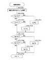
まず、コントローラ14は、車両の走行時に図3に示すように、車輪毎の減衰力制御処理を実行する。即ち、図3中のステップ1では初期設定を行い、次のステップ2で時間管理を行って、ステップ3以降の制御処理を行う制御サイクルを例えば数ms程度の値に調整する。そして、ステップ3ではセンサ入力を行い、ばね上加速度センサ10、ばね下加速度センサ11、横加速度センサ12および前後加速度センサ13等からの信号を読込む。 First, the
次のステップ4では、車輪毎のピストン加速度afr,arrおよび相対速度を演算して求める。この場合、ばね下加速度センサ11によるばね下側の加速度信号とばね上加速度センサ10によるばね上側の加速度信号とを減算処理することにより、ばね上,ばね下間のピストン加速度afr,arrが算出される。また、ピストン加速度afr,arrを積分することにより、各前輪2、各後輪3と車体1との間の上,下方向の相対速度が算出される。ピストン加速度afr,arrおよび相対速度は、ダンパの伸び側を正とし、縮み側を負として示す。In the
次のステップ5では、これらの演算結果に従った減衰力指令信号を入力する。また、次のステップ6では、横加速度センサ12からの横加速度信号に基づいて、車両の横加速度Ayの絶対値が変化しているか否か、即ち車両の横加速度Ayの絶対値が増加中または減少中のいずれかの状態か否かを判別するための制御判別係数ψを演算する。具体的には、図4に示す制御判別処理を行い、横加速度Ayから制御判別係数ψを算出する。そして、ステップ7では、制御判別係数ψに基づいて、輪荷重制御を実行するか否かを判定する。横加速度Ayは、車両の左側を正とし、右側を負として示す。In the
ステップ7で「YES」と判定するときには、車両の横加速度Ayの絶対値が増加中または減少中であるから、次のステップ8に移って輪荷重制御を行い、後述の図5に示すように、横加速度Ayおよびピストン加速度afr,arrに応じた車輪毎の減衰力指令信号IFR,IRRを演算する。そして、次のステップ9で車輪毎に減衰力指令信号(目標減衰力信号)を出力し、車輪毎の輪荷重を可変に制御するために減衰力の可変制御を行い、その後は、ステップ2以降の処理を繰返すようにする。If “YES” is determined in
また、ステップ7で「NO」と判定するときには、車両の横加速度Ayの絶対値が変化せずに一定となった状態であるから、ステップ10に移って車輪毎の減衰力指令信号の演算処理を、通常制御として実行する。通常制御としては、スカイフック制御等の制振制御や悪路走行中の悪路制御、ロールやアンチダイブ、スクオット制御等が行われる。そして、次のステップ9では、ステップ10で演算した各車輪の減衰力指令信号(目標減衰力信号)を出力して減衰力を可変に制御する。Further, when “NO” is determined in
なお、図3中のステップ7で、制御判別係数ψが零(ψ=0)と判別したときに通常制御を行う構成としたが、このときにも輪荷重制御を行う構成としてもよい。この場合、例えば制御判別係数ψが零(ψ=0)となったとき、制御判別係数ψを1サンプル遅延させて、零が算出される前の制御判別係数ψの値に変更し、減衰力指令信号IFR,IRRを演算してもよく、減衰力指令信号IFR,IRRを1サンプル遅延させて、前回の減衰力指令信号IFR,IRRを出力する構成としてもよい。また、図3中のステップ6とステップ7の間にカウンタを設け、制御判別係数ψが零(ψ=0)となる状態が所定時間だけ継続したときに、通常制御を行う構成としてもよい。In addition, although it was set as the structure which performs normal control when the control discrimination coefficient (psi) is discriminate | determined to zero ((psi) = 0) in
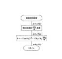
次に、図3中の制御判別処理について、図4を参照しつつ説明する。まず、ステップ11では、横加速度Ayを時間微分して横加加速度(dAy/dt)を演算する。次に、ステップ12では、以下の数1の式に示すように、横加速度Ayと横加加速度(dAy/dt)との積を用いて制御判別係数ψを演算した後、ステップ13に移ってリターンする。Next, the control determination process in FIG. 3 will be described with reference to FIG. First, in
次に、図5に示す輪荷重制御について説明する。まず、ステップ21では、以下の数2の式に基づいて、ピストン加速度afrから前輪側の指令電流値となる減衰力指令信号IFRを演算する。これに加えて、以下の数3の式に基づいて、ピストン加速度arrから後輪側の指令電流値となる減衰力指令信号IRRを演算する。Next, wheel load control shown in FIG. 5 will be described. First, at step 21, a damping force command signal IFR that is a front wheel side command current value is calculated from the piston acceleration afr based on the following equation (2). In addition, a damping force command signal IRR that is a rear wheel command current value is calculated from the piston acceleration arr based on the following equation (3).
ここで、符号関数sgn(ψ)は、数4の式に示すように、制御判別係数ψが正(ψ>0)のときに1を出力し、負(ψ<0)のときに−1を出力し、零(ψ=0)のときに零を出力するものである。また、制御ゲインKFR,KRR,I0FR,I0RRは、一定値でもよく、可変な値でもよい。制御ゲインKFR,KRR,I0FR,I0RRを一定値とする場合には、予めチューニングによって決められた一定値をステップ1の初期設定で読込む構成としてもよい。一方、制御ゲインKFR,KRR,I0FR,I0RRを可変に設定する場合には、例えば横加速度Ay、前後加速度Ax、車速vx、操舵角速度等を利用してドライバ操作状況や車両状況に応じて変化させる構成としてもよい。Here, the sign function sgn (ψ) outputs 1 when the control discrimination coefficient ψ is positive (ψ> 0) and −1 when negative (ψ <0), as shown in the equation (4). And zero is output when zero (ψ = 0). Further, the control gains KFR , KRR , I 0FR and I 0RR may be constant values or variable values. When the control gains KFR , KRR , I 0FR and I 0RR are set to constant values, a constant value determined in advance by tuning may be read by the initial setting in
数2の式に示すように、前輪側の減衰力指令信号IFRはピストン加速度afrに応じて変化し、車両の横加速度Ayの絶対値が増加中の場合は、前後加速度Axによらず前輪2の輪荷重をアップする、またはダウンさせにくくする。この場合、後輪側の減衰力指令信号IRRは、同様な作用が生じるように、減衰力指令信号IFRに対して符号関数の符号が逆になっている。このため、ピストン加速度afr,arrが同じ値であれば、後輪側の減衰力指令信号IRRは、前輪側の減衰力指令信号IFRと逆位相で変化する。As shown in the equation (2), the front wheel side damping force command signal IFR changes in accordance with the piston acceleration afr , and when the absolute value of the lateral acceleration Ay of the vehicle is increasing, the front accelerationAx is Regardless of this, the wheel load of the
また、数3の式に示すように、後輪側の減衰力指令信号IRRはピストン加速度arrに応じて変化し、車両の横加速度Ayの絶対値が減少中の場合は、前後加速度Axによらず後輪3の輪荷重をアップする、またはダウンさせにくくする。この場合、前輪側の減衰力指令信号IRRは、同様な作用が生じるように、後輪側の減衰力指令信号IRRに対して符号関数の符号が逆になっている。Further, as shown in
そして、減衰力指令信号IFR,IRRは、ピストン加速度afr,arrに比例してハード指令信号IHからソフト指令信号IS(IS>IH)まで増加する信号として演算される。The damping force command signals IFR and IRR are calculated as signals that increase from the hard command signal IH to the soft command signal IS (IS > IH ) in proportion to the piston accelerations afr and arr. .
次に、ステップ22〜25では、前輪側の減衰力指令信号IFRがハード指令信号IHとソフト指令信号ISとの間の範囲内の値となるように、前輪側の減衰力指令信号IFRの飽和処理を行う。具体的には、ステップ22では、ステップ21による前輪側の減衰力指令信号IFRがソフト指令信号ISより大きな値(IFR>IS)であるか否かを判定し、「YES」と判定したときには、次のステップ23に移って飽和処理を行い、減衰力指令信号IFRをソフト指令信号ISに設定する(IFR=IS)。Next, in step 22 to 25, so that the damping force command signal IFR of the front wheel side becomes a value within the range between the hard command signal IH and the soft command signal IS, front-wheel-side damping force command signalIFR saturation processing is performed. Specifically, in step 22, the damping force command signal IFR of the front wheel side is equal to or large than the soft command signalI S (I FR> I S ) in step 21, "YES" When the determination is made, the process proceeds to the next step 23, where saturation processing is performed, and the damping force command signal IFR is set to the soft command signal IS (IFR = IS ).
また、ステップ22で「NO」と判定するときには、減衰力指令信号IFRがソフト指令信号ISよりも小さいと判定できるので、次のステップ24に移って減衰力指令信号IFRがハード指令信号IHより小さい値(IFR<IH)であるか否かを判定する。そして、ステップ24で「YES」と判定したときには、次のステップ25に移って飽和処理を行い、減衰力指令信号IFRをハード指令信号IHに設定する(IFR=IH)。Further, when the CPU 51 determines "NO" in the step 22, since the damping force command signal IFR can be determined to be smaller than the soft command signal IS, proceeds to the next step 24 the damping force command signal IFR hard command signal It is determined whether or not the value is smaller than IH (IFR <IH ). If “YES” is determined in the step 24, the process proceeds to the next step 25, where saturation processing is performed, and the damping force command signal IFR is set to the hard command signal IH (IFR = IH ).
一方、ステップ24で「NO」と判定したときには、減衰力指令信号IFRがハード指令信号IHとソフト指令信号ISとの間の範囲内の値になっている(IH≦IFR≦IS)。このため、減衰力指令信号IFRはそのままの値に保持し、ステップ26に移行する。On the other hand, if “NO” is determined in step 24, the damping force command signal IFR is a value within the range between the hard command signal IH and the soft command signal IS (IH ≦ IFR ≦ IS ). For this reason, the damping force command signal IFR is held at the same value, and the routine proceeds to step 26.
次に、ステップ26〜29では、後輪側の減衰力指令信号IRRがハード指令信号IHとソフト指令信号ISとの間の範囲内の値となるように、前記ステップ22〜25とほぼ同様な飽和処理を行う。これにより、後輪側の減衰力指令信号IRRも、前輪側の減衰力指令信号IFRと同様に、ハード指令信号IHとソフト指令信号ISとの間の範囲内の値に設定される(IH≦IRR≦IS)。そして、ステップ26〜29による後輪側の減衰力指令信号IRRの飽和処理が終了すると、ステップ30に移ってリターンする。Next, in steps 26 to 29, the steps 22 to 25 are performed so that the damping force command signal IRR on the rear wheel side is a value within the range between the hard command signal IH and the soft command signal IS. Perform almost the same saturation treatment. As a result, the rear wheel side damping force command signal IRR is also set to a value within the range between the hard command signal IH and the soft command signal IS , similarly to the front wheel side damping force command signal IFR. (IH ≦ IRR ≦ IS ). Then, when the saturation processing of the damping force command signal IRR on the rear wheel side in steps 26 to 29 is completed, the routine proceeds to step 30 and returns.
なお、ソフト指令信号ISは、前回の減衰力指令信号IFR,IRRよりも予め決められた値分だけ指令信号を相対的にソフト側に変更するための信号であり、ソフトとハードの2段切替え信号を必ずしも意味するものではない。また、ソフト指令信号ISは、車速などの他の条件によって、変更してもよい。The soft command signal IS is a signal for changing the command signal to the soft side relatively by a predetermined value from the previous damping force command signals IFR and IRR . It does not necessarily mean a two-stage switching signal. Further, the soft command signal IS is by other conditions such as vehicle speed, may be changed.
本実施の形態によるサスペンション制御装置は、上述のような制御処理を実行するもので、次に、車両の走行時における減衰力指令信号IFR,IRRおよび輪荷重の特性について説明する。The suspension control apparatus according to the present embodiment executes the control process as described above. Next, characteristics of damping force command signals IFR and IRR and wheel load when the vehicle is traveling will be described.
まず、コントローラ14には、車両の走行時にばね上加速度センサ10、ばね下加速度センサ11からの加速度信号が入力されると共に、横加速度センサ12からの横加速度信号が入力される。このとき、コントローラ14は、ばね上加速度センサ10およびばね下加速度センサ11の加速度信号の差に基づいて、車輪毎のピストン加速度afr,arrを演算する。また、コントローラ14は、横加速度Ayを時間微分して横加加速度(dAy/dt)を演算すると共に、横加速度Ayおよび横加加速度(dAy/dt)の積によって制御判別係数ψを演算する。そして、コントローラ14は、制御判別係数ψおよびピストン加速度afr,arrを用いて減衰力指令信号IFR,IRRを演算する。First, the acceleration signal from the sprung
ここで、制御判別係数ψは、横加速度Ayに基づいて算出されるから、車両の前後加速度Axには無関係に決まり、横加速度Ayと横加加速度(dAy/dt)のいずれかが零のときに零となる。そして、減衰力指令信号IFR,IRRは、制御判別係数ψが正または負の値となるときに、ピストン加速度afr,arrに比例した値となる。Here, since the control discrimination coefficient ψ is calculated based on the lateral acceleration Ay , it is determined regardless of the longitudinal acceleration Ax of the vehicle, and either the lateral acceleration Ay or the lateral jerk (dAy / dt) is determined. It becomes zero when zero. The damping force command signals IFR and IRR are values proportional to the piston accelerations afr and arr when the control discrimination coefficient ψ is a positive or negative value.
従って、横加速度Ayの絶対値が増加中の場合には、前輪側の減衰力指令信号IFRは、前輪の輪荷重を増加させる、または前輪の輪荷重を減少させにくくする値に設定される。この前輪の輪荷重の変化に伴って、後輪の輪荷重は減少し、または増加しにくくなる。一方、横加速度Ayの絶対値が減少中の場合には、前輪側の減衰力指令信号IFRは、前輪の輪荷重を減少させる、または増加させにくくする値に設定される。この前輪の輪荷重の変化に伴って、後輪の輪荷重は増加し、または減少しにくくなる。Accordingly, when the absolute value of the lateral accelerationAy is increasing, the front wheel side damping force command signalIFR is set to a value that makes it difficult to increase the wheel load of the front wheel or to decrease the wheel load of the front wheel. The With the change in the wheel load of the front wheel, the wheel load of the rear wheel decreases or becomes difficult to increase. On the other hand, the absolute value of the lateral acceleration Ay is the case in the reduction, damping force command signal IFR of the front wheels is set to a value less likely to reduce the front wheel wheel load, or increase. With the change in the wheel load of the front wheel, the wheel load of the rear wheel increases or becomes difficult to decrease.
同様に、横加速度Ayの絶対値が増加中の場合には、後輪側の減衰力指令信号IRRは、後輪の輪荷重を減少させる、または後輪の輪荷重を増加させにくくする値に設定される。この後輪の輪荷重の変化に伴って、前輪の輪荷重は増加し、または減少しにくくなる。一方、横加速度Ayの絶対値が減少中の場合には、後輪側の減衰力指令信号IRRは、後輪の輪荷重を増加させる、または後輪の輪荷重を減少させにくくする値に設定される。この後輪の輪荷重の変化に伴って、前輪の輪荷重は減少し、または増加しにくくなる。Similarly, when the absolute value of the lateral accelerationAy is increasing, the damping force command signalIRR on the rear wheel side reduces the wheel load on the rear wheel or makes it difficult to increase the wheel load on the rear wheel. Set to a value. With the change in the wheel load of the rear wheel, the wheel load of the front wheel increases or becomes difficult to decrease. On the other hand, when the absolute value of the lateral accelerationAy is decreasing, the rear wheel side damping force command signalIRR increases the wheel load of the rear wheel or makes it difficult to decrease the wheel load of the rear wheel. Set to Along with the change in the wheel load of the rear wheel, the wheel load of the front wheel decreases or becomes difficult to increase.
即ち、本実施の形態では、例えば車両の旋回時のように、横加速度Ayの絶対値が変化するときに、上述のような輪荷重制御を行う。以上の輪荷重制御による効果を、図6を用いて具体的に説明する。図6は、車両の走行時における前輪1輪の減衰力指令信号IFR等の時間変化を模式的に示したものである。That is, in the present embodiment, the wheel load control as described above is performed when the absolute value of the lateral accelerationAy changes, for example, when the vehicle turns. The effect of the wheel load control described above will be specifically described with reference to FIG. FIG. 6 schematically shows temporal changes of the damping force command signalIFR and the like for one front wheel when the vehicle is traveling.
なお、図6では、前輪1輪だけの減衰力指令信号IFRだけを示したが、後輪側の減衰力指令信号IRRは、数3の式に基づいて、同様に求めることができる。例えば図6に示す前後加速度Axおよび横加速度Ayが発生し、後輪1輪のピストン加速度arrが図6に示す前輪のピストン加速度afrと同じ変化をする場合には、この後輪1輪の減衰力指令信号IRRは、図6に示す前輪1輪の減衰力指令信号IFRと逆位相になる。In FIG. 6, only the damping force command signal IFR for only one front wheel is shown, but the rear wheel damping force command signal IRR can be obtained in the same manner based on the equation (3). If the acceleration Ax and the lateral acceleration Ay is generated before and after 6, the piston acceleration arr of the rear wheels one wheel to the same change the front wheel of the piston acceleration afr shown in FIG. 6, for example, wheels thereafter damping force command signal IRR of one wheel will damping force command signal IFR and opposite phase of the
但し、前輪2と後輪3のそれぞれのピストン加速度afr,arrに対する減衰力指令信号IFR,IRRは、制御ゲインKFR,KRR,I0FR,I0RRのパラメータチューニングに依存する。このため、ピストン加速度afr,arrの大きさが同じ状態であっても、前輪2と後輪3の減衰力指令信号IFR,IRRは互いに同じ値が出力されるとは限らない。また、減衰力指令信号IFR,IRRに対する減衰力可変ダンパ6,9の減衰力は、前輪2と後輪3のそれぞれの状況および減衰力可変ダンパ6,9の仕様に依存する。このため、減衰力指令信号IFR,IRRが同じ値となっても、減衰力可変ダンパ6,9が同じ減衰力を発生するとは限らない。However, the damping force command signals IFR and IRR for the piston accelerations afr and arr of the
図6に示すように、例えば車両が直線運動した状態で加速や減速した場合には、前後加速度Axは変化するものの、横加速度Ayは変化しない。このため、前後加速度Axに拘らず、制御判別係数ψは零となり、減衰力指令信号IFRは一定値に保持される。As shown in FIG. 6, for example, when the vehicle is accelerated or decelerated in a linear motion state, the longitudinal acceleration Ax changes, but the lateral acceleration Ay does not change. Therefore, regardless of the longitudinal acceleration Ax , the control discrimination coefficient ψ is zero, and the damping force command signal IFR is held at a constant value.
一方、車両の旋回時のように、横加速度Ayの絶対値が変化するときには、減衰力指令信号IFRは、ピストン加速度afrに応じて変化する。具体的には、横加速度Ayが立上り区間では、減衰力指令信号IFRは、前輪2の輪荷重を減少させ、または増加しにくくするように、ハード側の特性となる。これにより、後輪3の輪荷重は増加し、または減少しにくくなる。また、横加速度Ayが立下り区間では、減衰力指令信号IFRは、前輪2の輪荷重を増加させ、または減少しにくくするように、ソフト側の特性となる。これにより、後輪3の輪荷重は減少し、または増加しにくくなる。On the other hand, when the absolute value of the lateral accelerationAy changes, such as when the vehicle turns, the damping force command signalIFR changes according to the piston accelerationafr . Specifically, in the period in which the lateral accelerationAy rises, the damping force command signalIFR has a hard-side characteristic so that the wheel load of the
この結果、本実施の形態では、横加速度Ayの増加と減少に応じて前輪2と後輪3の輪荷重を制御し、旋回時における操舵安定性と安定性を高めることができる。この理由は、次の通りである。As a result, in the present embodiment, the wheel load of the
熟練ドライバは、横加速度Ayが立上るときに減速し、横加速度Ayが立下るときに加速を行うことで、車両の操舵応答性と安定性を向上し、素早く安定したコーナリングを実現していることが分かっている。このとき、熟練ドライバは、横加速度Ayと前後加速度Axの関係が円を描くように、ハンドルの切り増し時にブレーキを操作して減速し、ハンドルの切り戻し時にアクセルを操作して加速する。即ち、熟練ドライバは、横加速度Ayの立上り時に前後加速度Axが減少し、横加速度Ayの立下り時に前後加速度Axが増加するように制御している。The skilled driver decelerates when the lateral accelerationAy rises and accelerates when the lateral accelerationAy falls, improving the steering response and stability of the vehicle and realizing quick and stable cornering I know that At this time, the skilled driver operates the brake when the steering wheel is turned up and decelerates and accelerates the accelerator when the steering wheel is turned back so that the relationship between the lateral acceleration Ay and the longitudinal acceleration Ax draws a circle. . In other words, a skilled driver, the acceleration Ax is reduced before and after the rising edge of the lateral acceleration Ay, lateral acceleration A longitudinal acceleration Ax during the fall ofy is controlled so as to increase.
非特許文献1のG-Vectoring制御では、ドライバの運転によって発生した横加速度Ayに応じて、熟練ドライバのような前後加速度Axを制動力制御を行うことによって発生させる。これにより、熟練ドライバのような旋回を実現している。In the G-Vectoring control of
このような熟練ドライバによる前後加速度Axの制御を、輪荷重の観点で考えると、減速することは、前輪側に荷重移動を発生させることであり、前輪2の輪荷重は増加し、後輪3の輪荷重は減少する。一方、加速することは、後輪側に荷重移動を発生させることであり、前輪2の輪荷重は減少し、後輪3の輪荷重は増加する。Such control of the front and rear by a skilled driver acceleration Ax, considering in terms of wheel load, the deceleration is to generate a load transfer to the front wheel side, the wheel loads of the
つまり、熟練ドライバであれば、加速または減速するような横加速度Ayの状況では、制御サスペンションが前輪2ないし後輪3の輪荷重を増加または減少させるように制御すれば、輪荷重制御によって操舵応答性と安定性を両立した旋回を実現することができる。本実施の形態では、上述のような観点に基づいて、前後加速度Axに関係なく、横加速度Ayの変化に応じた減衰力指令信号IFR,IRRを出力し、前輪と後輪の輪荷重を制御している。In other words, if the driver is a skilled driver, in the situation of the lateral accelerationAy that accelerates or decelerates, if the control suspension is controlled so as to increase or decrease the wheel load of the
これは車両運動に応じたサスペンション制御であるため、横滑り防止装置の非作動時から、車両運動状態に応じた的確な輪荷重制御を行うことができる。このため、横滑り防止装置が作動するような不安定な走行状態に対する陥り易さを低減することができる。また、車両運動状態に応じた輪荷重制御であるため、例えば横滑り防止装置が作動するときにダンパ6,9が伸び切っている状態、または縮み切っている状態であっても、その状態になる以前から輪荷重を制御することができる。このため、横滑り防止装置の作動時に輪荷重の制御ができない状態であっても、この状態も考慮された輪荷重を事前に車両に付与することができる。 Since this is suspension control according to the vehicle motion, accurate wheel load control according to the vehicle motion state can be performed from when the skid prevention device is not operated. For this reason, the ease of falling into an unstable traveling state in which the skid prevention device operates can be reduced. In addition, since the wheel load control is performed according to the vehicle motion state, for example, even when the
このような本実施の形態の有効性を検証するために、フルビークルシミュレーションによる走行実験を行った。そのときの右前輪の輪荷重の時間変化を図7に示す。図7中で、実線は通常制御と輪荷重制御を行う本実施の形態を示し、破線は通常制御だけを行う比較例を示している。図7に示すように、横加速度Ayの立上りと立下りで制御判別係数ψの符号が反転しており、本実施の形態では、比較例に比べて、制御判別係数ψが正となって前輪の輪荷重を増加させる(後輪3の輪荷重を減少させる)区間では、前輪2の輪荷重の抜けを小さくし、かつ前輪2の輪荷重の増加を大きくしていることが分かる。逆に、本実施の形態では、比較例に比べて、制御判別係数ψが負となって前輪2の輪荷重を減少させる(後輪3の輪荷重を増加させる)区間では、前輪2の輪荷重の抜けを大きくし、かつ前輪2の輪荷重の増加を小さくしていることが分かる。In order to verify the effectiveness of the present embodiment, a running experiment using a full vehicle simulation was performed. The time change of the wheel load of the right front wheel at that time is shown in FIG. In FIG. 7, the solid line indicates the present embodiment in which normal control and wheel load control are performed, and the broken line indicates a comparative example in which only normal control is performed. As shown in FIG. 7, the sign of the control discrimination coefficient ψ is inverted between the rise and fall of the lateral acceleration Ay , and in this embodiment, the control discrimination coefficient ψ is positive compared to the comparative example. It can be seen that in the section where the wheel load of the front wheel is increased (the wheel load of the
かくして、第1の実施の形態では、横加速度Ayの増加中または減少中にピストン加速度afr,arrに応じた減衰力指令信号IFR,IRRを出力するから、ドライバのハンドル操作および車両状態に応じた輪荷重制御を行うことができる。このため、横滑り防止装置の作動によらず車両運転性能を向上することができ、例えば旋回時における車両の限界性能を高めることができる。また、ドライバのハンドル操作に応じて横滑り防止装置が作動する前から車両状態に適した的確な輪荷重制御を行うことができるから、車両の安定性を高めて横滑り防止装置が作動しにくくなると共に、通常時の運転感覚が向上する。Thus, in the first embodiment, the damping force command signals IFR and IRR corresponding to the piston accelerations afr and arr are output while the lateral acceleration Ay is increasing or decreasing. Wheel load control according to the vehicle state can be performed. For this reason, the vehicle driving performance can be improved regardless of the operation of the skid prevention device, and for example, the limit performance of the vehicle during turning can be increased. In addition, since it is possible to perform precise wheel load control suitable for the vehicle state before the skid prevention device is activated according to the driver's steering operation, the stability of the vehicle is improved and the skid prevention device is difficult to operate. The driving feeling during normal operation is improved.
さらに、特許文献1に記載の横滑り防止装置では、複雑な場合分けと演算によって制動輪の判別を行い、制動輪の輪荷重を増加し、非制動輪の輪荷重を減少させる。これに対し、第1の実施の形態では、横加速度Ayの情報のみで輪荷重を増減させる車輪を判別するから、複雑な場合分けや演算を必要とせず、判別処理を簡略化することができる。Further, in the skid prevention device described in
また、非特許文献1のG-Vectoring制御では、車両の横運動に応じて車両の減速制御を行うから、例えば車線変更時に減速制御が作動し、ドライバの意図しない速度変化が生じる可能性がある。これに対し、第1の実施の形態では、横加速度Ayに応じて前輪または後輪の輪荷重を制御するだけであり、車両の加減速を制御することはない。このため、車線変更時でも速度を一定に保つことできると共に、ドライバのアクセルやブレーキ操作に合わせて車両を速やかに加速および減速することができ、素早く安定したコーナリングを実現することができる。Further, in the G-Vectoring control of
次に、図8および図9は本発明の第2の実施の形態を示している。第2の実施の形態の特徴は、横加速度の増加および減少がないときには、前後加速度に応じて前輪と後輪の輪荷重を制御する構成としたことにある。なお、第2の実施の形態では、前述した第1の実施の形態と同一の構成要素に同一の符号を付し、その説明を省略するものとする。 Next, FIG. 8 and FIG. 9 show a second embodiment of the present invention. The feature of the second embodiment resides in that the wheel loads of the front wheels and the rear wheels are controlled according to the longitudinal acceleration when there is no increase or decrease in lateral acceleration. In the second embodiment, the same components as those in the first embodiment are denoted by the same reference numerals, and the description thereof is omitted.
第2の実施の形態によるコントローラ21も、第1の実施の形態によるコントローラ14とほぼ同様に構成され、図3に示す車輪毎の減衰力制御処理を実行すると共に、図5に示す輪荷重制御を実行する。但し、図3中の制御判別処理が第1の実施の形態と異なり、横加速度Ayの絶対値の増加および減少がないときには、前後加速度Axに応じた制御判別係数ψを出力する構成となっている。The controller 21 according to the second embodiment is configured in substantially the same manner as the
そこで、第2の実施の形態による制御判別処理について、図8を参照しつつ説明する。まず、ステップ31では、横加速度Ayを時間微分して横加加速度(dAy/dt)を演算する。次に、ステップ32では、以下の数5の式に示すように、横加速度Ayおよび前後加速度Axに基づいて制御判別係数ψを演算する。具体的に説明すると、数5の式のうち前後加速度Axに比例する項は、横加速度Ayが零以外(Ay≠0)のときには符号関数の二乗部分が1となるから、零が算出される。一方、前後加速度Axに比例する項は、横加速度Ayが零のときには、前後加速度Axがそのまま算出される。これにより、数5の式のうち前後加速度Axに比例する項は、横加速度Ayと前後加速度Axとを用いて横加速度Ayが変化しないときの成分を演算する。Therefore, the control determination process according to the second embodiment will be described with reference to FIG. First, in step 31, the lateral acceleration Ay time differentiation on calculating the lateral jerk (dAy / dt). Next, in step 32, a control discrimination coefficient ψ is calculated based on the lateral acceleration Ay and the longitudinal acceleration Ax as shown in the following equation (5). More specifically, the term proportional to the longitudinal acceleration Ax in the
また、数5の式のうち横加速度Ayに比例する項は、第1の実施の形態による制御判別処理と同様に、横加速度Ayと横加加速度(dAy/dt)との積が算出される。これにより、横加速度Ayに比例する項は、横加速度Ayが変化するときの成分を演算する。そして、数5の式は、前後加速度Axに比例する項と横加速度Ayに比例する項とを加算することによって、制御判別係数ψを算出する。ステップ32でこのような演算が終了すると、ステップ33に移ってリターンする。Also, term proportional to the lateral acceleration Ay of the
第2の実施の形態によるサスペンション制御装置は、上述のような制御処理を実行するもので、次に、車両の走行時における減衰力指令信号IFR,IRRの特性について図9を参照しつつ説明する。図9は、車両の走行時における前輪1輪の減衰力指令信号IFR等の時間変化を模式的に示したものである。The suspension control apparatus according to the second embodiment executes the control process as described above. Next, referring to FIG. 9, the characteristics of the damping force command signals IFR and IRR when the vehicle is traveling are described. explain. FIG. 9 schematically shows changes over time in the damping force command signalIFR and the like for one front wheel when the vehicle is traveling.
図9に示すように、車両の旋回時のように、横加速度Ayの絶対値が変化するときには、減衰力指令信号IFRは、ピストン加速度afrに応じて変化する。具体的には、横加速度Ayの立上り区間では、減衰力指令信号IFRは、前輪の輪荷重を減少させ、または増加しにくくするように、ハード側の特性となる。これにより、後輪の輪荷重は増加し、または減少しにくくなる。また、横加速度Ayの立下り区間では、減衰力指令信号IFRは、前輪の輪荷重を増加させ、または減少しにくくするように、ソフト側の特性となる。これにより、後輪の輪荷重は減少し、または増加しにくくなる。この点は、第1の実施の形態と同様である。As shown in FIG. 9, when the absolute value of the lateral accelerationAy changes, such as when the vehicle turns, the damping force command signalIFR changes according to the piston accelerationafr . Specifically, in the rising section of the lateral accelerationAy , the damping force command signalIFR has a hard-side characteristic so that the wheel load of the front wheels is reduced or hardly increased. As a result, the wheel load of the rear wheel is unlikely to increase or decrease. Further, in the falling section of the lateral accelerationAy , the damping force command signalIFR has a soft characteristic so that the wheel load of the front wheels is increased or is less likely to decrease. Thereby, the wheel load of the rear wheel is reduced or hardly increased. This point is the same as in the first embodiment.
一方、車両が直線運動した状態で加速や減速した場合には、前後加速度Axは変化するものの、横加速度Ayは変化しない。しかし、第2の実施の形態では、前後加速度Axだけが変化する場合でも、減衰力指令信号IFR,IFRは、ピストン加速度afrに応じて変化する。具体的には、前後加速度Ax(加速または減速)の立上り区間では、減衰力指令信号IFRは、前輪の輪荷重を減少させ、または増加しにくくするように、ハード側の特性となる。これにより、後輪の輪荷重は増加し、または減少しにくくなる。また、横加速度Ayの立下り区間では、減衰力指令信号IFRは、前輪の輪荷重を増加させ、または減少しにくくするように、ソフト側の特性となる。これにより、後輪の輪荷重は減少し、または増加しにくくなる。この結果、第2の実施の形態では、輪荷重をアップさせる割合は、前後加速度Axに応じて可変に設定される。On the other hand, when the vehicle accelerates or decelerates in a linear motion, the longitudinal acceleration Ax changes, but the lateral acceleration Ay does not change. However, in the second embodiment, even when only the longitudinal acceleration Ax changes, the damping force command signals IFR and IFR change according to the piston acceleration afr . Specifically, in the rising section of the longitudinal acceleration Ax (acceleration or deceleration), the damping force command signal IFR has a hard-side characteristic so that the wheel load of the front wheels is reduced or hardly increased. As a result, the wheel load of the rear wheel is unlikely to increase or decrease. Further, in the falling section of the lateral accelerationAy , the damping force command signalIFR has a soft characteristic so that the wheel load of the front wheels is increased or is less likely to decrease. Thereby, the wheel load of the rear wheel is reduced or hardly increased. As a result, in the second embodiment, the proportion for up wheel load is variably set in accordance with the longitudinal acceleration Ax.
かくして、第2の実施の形態でも、第1の実施の形態とほぼ同様の作用効果を得ることができる。特に、第2の実施の形態では、横加速度Ayが増加および減少するときに輪荷重制御を行うのに加えて、横加速度Ayの増加および減少がないときにも前後加速度Axに応じて輪荷重制御を行う構成とした。このため、車両の旋回と直進の両方の場合に、車両状態に応じた輪荷重制御を行うことができ、操舵応答性および安定性からなる旋回性能を高めることができるのに加え、直進制動時および駆動時の応答性および安定性からなる直進制駆動性能を高めることができる。この結果、車両の旋回性能と直進制駆動性能を両立させることができる。Thus, in the second embodiment, it is possible to obtain substantially the same operational effects as those in the first embodiment. In particular, in the second embodiment, in addition to performing wheel load control when the lateral acceleration Ay increases and decreases, depending on the lateral acceleration Ay longitudinal increase and when there is no decrease even acceleration Ax Wheel load control. For this reason, it is possible to perform wheel load control according to the vehicle state in both cases of turning and straight traveling of the vehicle, and it is possible to improve the turning performance consisting of steering response and stability, and at the time of straight braking. Further, it is possible to improve the straight driving control performance including the response and stability during driving. As a result, both the turning performance of the vehicle and the straight drive control performance can be achieved.
次に、図10は本発明の第3の実施の形態を示している。第3の実施の形態の特徴は、前後加速度Axを用いて制御ゲインKFR,KRRを可変に設定する構成としたことにある。なお、第3の実施の形態では、前述した第1の実施の形態と同一の構成要素に同一の符号を付し、その説明を省略するものとする。Next, FIG. 10 shows a third embodiment of the present invention. The feature of the third embodiment is that the control gains KFR and KRR are variably set using the longitudinal acceleration Ax . Note that in the third embodiment, the same components as those in the first embodiment described above are denoted by the same reference numerals, and description thereof is omitted.
第3の実施の形態によるコントローラ31も、第1,第2の実施の形態によるコントローラ14,21とほぼ同様に構成され、図3に示す車輪毎の減衰力制御処理を実行すると共に、図4に示す制御判別処理、または図8に示す制御判別処理を実行する。但し、図3中の輪荷重制御が第1の実施の形態と異なり、制御ゲインKFR,KRRが前後加速度Axを用いて可変に設定されると共に、この制御ゲインKFR,KRRを用いて減衰力指令信号IFR,IRRを演算する構成となっている。The controller 31 according to the third embodiment is configured in substantially the same manner as the
このため、第3の実施の形態による輪荷重制御では、図10に示すように、まずステップ41で、以下の数6および数7の式に示すように、前後加速度Axおよび横加速度Ayに基づいて制御ゲインKFR,KRRを演算する。但し、数6および数7の式中でCFR,CRR,C0FR,C0RRは予め設定された定数である。その後、第1の実施の形態と同様に、ステップ21以降の処理を行い、制御ゲインKFR,KRRを用いて減衰力指令信号IFR,IRRを演算する。Therefore, in the wheel load control according to the third embodiment, as shown in FIG. 10, first, in step 41, as shown in the following
ここで、第3の実施の形態による制御ゲインKFR,KRRを演算処理について具体的に説明する。数6および数7の式に示すように、前後加速度Ax、横加速度Ayおよび横加加速度(dAy/dt)の積が正のときには、前後加速度Axの大きさに応じて制御ゲインKFR,KRRを大きくする。一方、前後加速度Ax、横加速度Ayおよび横加加速度(dAy/dt)の積が負のときには、前後加速度Axの大きさに応じて制御ゲインKFR,KRRを小さくする。このような演算を行うのは、次の理由によるものである。Here, the processing for calculating the control gains KFR and KRR according to the third embodiment will be specifically described. As shown in the equations (6) and (7), when the product of the longitudinal acceleration Ax , the lateral acceleration Ay and the lateral jerk (dAy / dt) is positive, the control gain K depends on the magnitude of the longitudinal acceleration Ax.Increase FR andKRR . On the other hand, when the product of the longitudinal acceleration Ax , the lateral acceleration Ay and the lateral jerk (dAy / dt) is negative, the control gains KFR and KRR are reduced according to the magnitude of the longitudinal acceleration Ax . Such an operation is performed for the following reason.
G-Vectoring制御では、横加速度Ayと横加加速度(dAy/dt)との積が正となって減速を行うときにドライバが加速(Ax>0)を行ったり、横加速度Ayと横加加速度(dAy/dt)との積が負となって加速を行うときにドライバが減速(Ax<0)を行ったりすると、車両はドライバの操舵に応答しにくくなり、車両の操舵応答性および安定性は低下する傾向がある。In G-Vectoring control, the driver performs acceleration (Ax > 0) when the product of the lateral acceleration Ay and the lateral jerk (dAy / dt) is positive and decelerates, or the lateral acceleration Ay If the driver decelerates (Ax <0) when accelerating when the product of the lateral jerk (dAy / dt) is negative, the vehicle becomes difficult to respond to the steering of the driver, and the steering response of the vehicle Tend to decline.
このため、本実施の形態では、G-Vectoring制御で減速を行うときにドライバが加速操作を行ったとき、またはG-Vectoring制御で加速を行うときにドライバが減速操作を行ったときには、制御ゲインKFR,KRRを大きくする。これにより、輪荷重制御によって輪荷重の増加または減少の効果を大きくし、ドライバの誤った運転操作による操舵応答性および安定性の低下を抑制することができる。For this reason, in this embodiment, when the driver performs an acceleration operation when performing deceleration with G-Vectoring control, or when the driver performs a deceleration operation when performing acceleration with G-Vectoring control, the control gainIncrease KFR and KRR . As a result, the effect of increasing or decreasing the wheel load can be increased by the wheel load control, and the deterioration of the steering response and stability due to an erroneous driving operation of the driver can be suppressed.
一方、本実施の形態では、G-Vectoring制御で減速を行うときにドライバが減速操作を行ったとき、またはG-Vectoring制御で加速を行うときにドライバが加速操作を行ったときには、制御ゲインKFR,KRRを小さくする。この場合、ドライバの運転操作による前後加速度Axによって輪荷重の移動を作り出すことができるから、輪荷重制御の効果が小さくても、ドライバの運転操作によって操舵応答性および安定性を向上することができる。On the other hand, in this embodiment, when the driver performs a deceleration operation when performing deceleration with G-Vectoring control, or when the driver performs an acceleration operation when performing acceleration with G-Vectoring control, the control gain KReduce FR andKRR . In this case, since the wheel load can be moved by the longitudinal accelerationAx caused by the driving operation of the driver, the steering response and stability can be improved by the driving operation of the driver even if the effect of the wheel load control is small. it can.
以上の点を考慮して、本実施の形態では、前後加速度Ax、横加速度Ayおよび横加加速度(dAy/dt)の積が正のときには、前後加速度Axの大きさに応じて制御ゲインKFR,KRRを大きくし、輪荷重制御の効果を大きくしている。一方、前後加速度Ax、横加速度Ayおよび横加加速度(dAy/dt)の積が負のときには、前後加速度Axの大きさに応じて制御ゲインKFR,KRRが小さくなるから、輪荷重制御の効果は小さくなっている。Considering the above points, in this embodiment, when the product of the longitudinal acceleration Ax , the lateral acceleration Ay and the lateral jerk (dAy / dt) is positive, the control is performed according to the magnitude of the longitudinal acceleration Ax. The gains KFR and KRR are increased to increase the effect of wheel load control. On the other hand, when the product of the longitudinal acceleration Ax , the lateral acceleration Ay and the lateral jerk (dAy / dt) is negative, the control gains KFR and KRR are reduced according to the magnitude of the longitudinal acceleration Ax. The effect of load control is small.
かくして、第3の実施の形態でも、第1の実施の形態とほぼ同様の作用効果を得ることができる。特に、第3の実施の形態では、前後加速度Axに応じて制御ゲインKFR,KRRを可変に設定するから、例えばドライバの誤った運転操作の影響を抑制し、車両の操舵応答性および安定性をさらに高めることができる。Thus, in the third embodiment, substantially the same operational effects as in the first embodiment can be obtained. In particular, in the third embodiment, since the control gains KFR and KRR are variably set according to the longitudinal acceleration Ax , for example, the influence of the driver's erroneous driving operation is suppressed, and the vehicle steering response and Stability can be further increased.
なお、第3の実施の形態では、前後加速度Ax等に基づいて制御ゲインKFR,KRRを可変に設定する構成とした。しかし、本発明はこれに限らず、例えば以下の数8および数9の式に示すように、車速vxと操舵角θに基づいて制御ゲインKFR,KRRを可変に設定する構成としてもよい。In the third embodiment, the control gains KFR and KRR are variably set based on the longitudinal acceleration Ax and the like. However, the present invention is not limited to this. For example, as shown in the following equations (8) and (9), the control gains KFR and KRR may be variably set based on the vehicle speed vx and the steering angle θ. Good.
車速vxに対して操舵角θが大きい、または操舵角θに対して車速vxが大きいと、車両は限界走行に陥り易くなる。従って、数8および数9の式では、制御ゲインKFR,KRRを車速vxと操舵角θとの積に比例させて大きくする。これにより、限界走行に近付くに従って制御ゲインKFR,KRRを大きくして、輪荷重制御の効果を大きくすることができ、車両の操舵応答性および安定性を高めることができる。Vehicle speed v is greater steering angle theta with respect tox, or when the vehicle speed vx is larger than the steering angle theta, the vehicle tends to fall into maximal running. Therefore, in the equations (8) and (9), the control gains KFR and KRR are increased in proportion to the product of the vehicle speed vx and the steering angle θ. As a result, the control gains KFR and KRR can be increased as the vehicle approaches the limit running, so that the effect of wheel load control can be increased, and the steering response and stability of the vehicle can be improved.
なお、前記各実施の形態では、サスペンション装置4,7は、所謂セミアクティブダンパと呼ばれる減衰力調整式の油圧緩衝器からなる減衰力可変ダンパ6,9を備える構成とした。しかし、本発明はこれに限らず、例えば空圧や油圧のアクティブサスペンションのように、流体を供給または排出して内部の圧力を増減させることによって輪荷重を調整可能な圧力シリンダを用いる構成としてもよい。また、流体を利用するサスペンション装置に限らず、ボールネジ式や電磁式のアクティブサスペンション等にも適用することができる。 In each of the above-described embodiments, the
また、前記各実施の形態では、横加速度Ayの絶対値が増加中および減少中の場合は、前輪側と後輪側の輪荷重(減衰力指令信号IFR,IRR)を両方とも制御する構成としたが、前輪側と後輪側のうちいずれか一方のみの輪荷重を制御する構成としてもよい。In each of the above embodiments, when the absolute value of the lateral accelerationAy is increasing or decreasing, both wheel loads (damping force command signalsIFR andIRR ) on the front wheel side and the rear wheel side are controlled. However, the wheel load on only one of the front wheel side and the rear wheel side may be controlled.
また、前記各実施の形態では、横加速度Ayの絶対値が増加中および減少中の両方の場合に、輪荷重制御を行う構成としたが、横加速度Ayの絶対値が増加中および減少中のうちいずれか一方の場合にのみ、輪荷重制御を行う構成としてもよい。In each of the above embodiments, the wheel load control is performed when the absolute value of the lateral accelerationAy is both increasing and decreasing. However, the absolute value of the lateral accelerationAy is increasing and decreasing. It is good also as a structure which performs wheel load control only in one of the cases.
また、前記各実施の形態では、前後加速度センサ13を設ける構成としたが、第1の実施の形態のように、減衰力指令信号IFR,IRRの演算に前後加速度Axを使用しないときには、前後加速度センサ13を省く構成としてもよい。Further, in each embodiment, although a configuration in which the
また、前記各実施の形態では、ばね上加速度センサ10とばね下加速度センサ11を用いて、ピストン加速度afr,arrを演算により求める構成とした。しかし、本発明はこれに限るものではなく、例えば車体1の高さを検出する車高センサからの信号を用いてピストン加速度afr,arrを演算により求める構成としてもよい。In each of the above embodiments, the piston accelerations afr and arr are obtained by calculation using the sprung
また、前記各実施の形態では、制御判別係数ψの符号反転によって、減衰力指令信号IFR,IRRが急激に切り替わり輪荷重が振動することがあるので、制御判別係数ψや減衰力指令信号IFR,IRRに、低域通過型フィルタを付加する構成としてもよい。In each of the above embodiments, the damping force command signals IFR and IRR are suddenly switched by the sign inversion of the control discrimination coefficient ψ, and the wheel load may vibrate. Therefore, the control discrimination coefficient ψ and the damping force command signal A low pass filter may be added to IFR and IRR .
さらに、前記各実施の形態では、横加速度センサ12と前後加速度センサ13を用いて横加速度Ayと前後加速度Axを検出する構成としたが、横加速度Ayと前後加速度Axが検出可能であれば、これら以外のセンサを用いる構成としてもよい。Furthermore, in each embodiment, a configuration for detecting a lateral acceleration Ay and the longitudinal acceleration Ax using the lateral acceleration sensor 12 a
1 車体
2 前輪
3 後輪
4,7 サスペンション装置
5,8 ばね
6,9 減衰力可変ダンパ(減衰力調整式緩衝器)
10 ばね上加速度センサ
11 ばね下加速度センサ
12 横加速度センサ
13 前後加速度センサ
14,21,31 コントローラ(制御手段)DESCRIPTION OF
DESCRIPTION OF
Claims (7)
Translated fromJapanese前記制御手段は、
前記車両の横加速度の絶対値が増加中の場合は、前記上下方向加速度に応じて前輪の輪荷重を前記横加速度の絶対値の増加前に比べアップする、またはダウンさせにくくし、
および/または、
前記車両の横加速度の絶対値が減少中の場合は、前記上下方向加速度に応じて後輪の輪荷重を前記横加速度の絶対値の減少前に比べアップする、またはダウンさせにくくするように、前記輪荷重調整機構を制御する構成としたことを特徴とするサスペンション制御装置。Provided interposed between a vehicle body and a wheel of a vehicle, and wheel load adjustment mechanism capable of adjusting the wheel load of the wheel by adjusting the force generated in the direction of distance between the vehicle body andthe wheel, Control means for controlling the wheel load adjustment mechanism,and detection means for detecting lateral acceleration of the vehicle and vertical acceleration between the vehicle body and the wheel ,
The control means includes
When the absolute value of the lateral acceleration of the vehicle is increasing, the wheel load ofthe front wheelis increased orreducedaccording to thevertical acceleration compared tobefore the increase of the absolute value of the lateral acceleration ,
And / or
When the absolute value of the lateral acceleration of the vehicle is decreasing, the wheel load of the rear wheel is increased ordecreasedaccording to the vertical accelerationcompared tobefore the absolute value of the lateral acceleration is decreased . A suspension control device characterized by controlling the wheel load adjusting mechanism.
前記車両の横加速度の絶対値が増加中の場合は、前記上下方向加速度に応じて後輪の輪荷重を前記横加速度の絶対値の増加前に比べダウンする、またはアップさせにくくし、When the absolute value of the lateral acceleration of the vehicle is increasing, the wheel load of the rear wheel is lowered or made difficult to increase compared to before the increase of the absolute value of the lateral acceleration according to the vertical acceleration,
および/または、And / or
前記車両の横加速度の絶対値が減少中の場合は、前記上下方向加速度に応じて前輪の輪荷重を前記横加速度の絶対値の減少前に比べダウンする、またはアップさせにくくするように、前記輪荷重調整機構を制御する構成とした請求項1ないし4のいずれかに記載のサスペンション制御装置。When the absolute value of the lateral acceleration of the vehicle is decreasing, the wheel load of the front wheels is reduced or made difficult to increase compared to before the decrease of the absolute value of the lateral acceleration according to the vertical acceleration. The suspension control device according to claim 1, wherein the suspension control device is configured to control a wheel load adjustment mechanism.
前記輪荷重調整機構は、指令電流値に従って前記輪荷重を増減させるように前記車体と前記車輪との間の距離方向に生じる力を調整し、
前記制御手段は、前記横加速度Ay、横加加速度dAy/dt、前輪側と後輪側の前記上下方向加速度afr,arr、チューニング制御ゲインKFR,KRR,I0FR,I0RRおよび符号関数sgnを用いて、前輪側の指令電流値IFRおよび/または後輪側の指令電流値IRRが
The wheel load adjusting mechanism adjusts the forces occurring distance direction between the vehicle body andthe wheel so as to increaseor decrease the thus the wheel loadon the command currentvalue,
The control means,the lateral acceleration Ay, lateral jerk dAy / dt,the vertical acceleration afr of the front wheel side and rear wheel side, arr, tuning control gainsK FR, K RR, I0 FR , I0 RR and Using the sign function sgn, the front wheel side command current value IFR and / or the rear wheel side command current value IRR
前記車体と前記車輪との間の上下方向加速度を検出する検出手段は、少なくとも1つのばね上加速度センサと、前記各前輪側および前記各後輪側にそれぞれ設けられたばね下加速度センサとを有する請求項1ないし6のいずれかに記載のサスペンション制御装置。The detection means for detecting the vertical acceleration between the vehicle body and the wheel includes at least one sprung acceleration sensor, and unsprung acceleration sensors respectively provided on the front wheel side and the rear wheel side. Item 7. The suspension control device according to any one of Items 1 to 6.
Priority Applications (5)
| Application Number | Priority Date | Filing Date | Title |
|---|---|---|---|
| JP2010194247AJP5572485B2 (en) | 2010-08-31 | 2010-08-31 | Suspension control device |
| KR1020110087176AKR101826356B1 (en) | 2010-08-31 | 2011-08-30 | Suspension control apparatus |
| US13/221,175US9211875B2 (en) | 2010-08-31 | 2011-08-30 | Suspension control apparatus |
| CN201110280591.9ACN102381152B (en) | 2010-08-31 | 2011-08-31 | Suspension control apparatus |
| DE102011081866ADE102011081866A1 (en) | 2010-08-31 | 2011-08-31 | Suspension control device |
Applications Claiming Priority (1)
| Application Number | Priority Date | Filing Date | Title |
|---|---|---|---|
| JP2010194247AJP5572485B2 (en) | 2010-08-31 | 2010-08-31 | Suspension control device |
Publications (2)
| Publication Number | Publication Date |
|---|---|
| JP2012051433A JP2012051433A (en) | 2012-03-15 |
| JP5572485B2true JP5572485B2 (en) | 2014-08-13 |
Family
ID=45566398
Family Applications (1)
| Application Number | Title | Priority Date | Filing Date |
|---|---|---|---|
| JP2010194247AExpired - Fee RelatedJP5572485B2 (en) | 2010-08-31 | 2010-08-31 | Suspension control device |
Country Status (5)
| Country | Link |
|---|---|
| US (1) | US9211875B2 (en) |
| JP (1) | JP5572485B2 (en) |
| KR (1) | KR101826356B1 (en) |
| CN (1) | CN102381152B (en) |
| DE (1) | DE102011081866A1 (en) |
Families Citing this family (43)
| Publication number | Priority date | Publication date | Assignee | Title |
|---|---|---|---|---|
| JP5143103B2 (en)* | 2009-09-30 | 2013-02-13 | 日立オートモティブシステムズ株式会社 | Vehicle motion control device |
| DE102010003205B4 (en)* | 2010-03-24 | 2020-01-16 | Ford Global Technologies, Llc | Method for determining the vertical acceleration, the longitudinal angular acceleration and the transverse angular acceleration of a body, in particular a motor vehicle |
| US9162573B2 (en) | 2010-06-03 | 2015-10-20 | Polaris Industries Inc. | Electronic throttle control |
| JP5671306B2 (en)* | 2010-11-10 | 2015-02-18 | カヤバ工業株式会社 | Suspension device |
| WO2013100121A1 (en)* | 2011-12-28 | 2013-07-04 | 日産自動車株式会社 | Vehicle control device |
| EP2712782B1 (en)* | 2012-09-28 | 2018-01-31 | Hitachi, Ltd. | Method and apparatus for performing driving assistance |
| EP2917054B1 (en) | 2012-11-07 | 2018-09-05 | Polaris Industries Inc. | Vehicle having suspension with continuous damping control |
| US9205717B2 (en) | 2012-11-07 | 2015-12-08 | Polaris Industries Inc. | Vehicle having suspension with continuous damping control |
| US20140257627A1 (en)* | 2013-03-11 | 2014-09-11 | Ford Global Technologies, Llc | Potential chassis damage identification and notification system |
| JP6275416B2 (en)* | 2013-08-30 | 2018-02-07 | 日立オートモティブシステムズ株式会社 | Vehicle behavior control device |
| SE540723C2 (en)* | 2013-11-29 | 2018-10-23 | Bae Systems Haegglunds Ab | Tilt reduction spring lock for motor vehicles |
| CN107406094B (en) | 2014-10-31 | 2020-04-14 | 北极星工业有限公司 | System and method for controlling a vehicle |
| DE102014226490A1 (en)* | 2014-12-18 | 2016-06-23 | Volkswagen Aktiengesellschaft | Device and method for reporting an extraordinary stress on a chassis of a means of transportation |
| MX2017014403A (en) | 2015-05-15 | 2018-04-11 | Polaris Inc | UTILITY VEHICLE. |
| DE102015011517B3 (en)* | 2015-09-03 | 2016-09-08 | Audi Ag | Method for determining a current level position of a vehicle |
| JP6198181B2 (en) | 2015-11-06 | 2017-09-20 | マツダ株式会社 | Vehicle behavior control device |
| JP6252993B2 (en) | 2015-11-06 | 2017-12-27 | マツダ株式会社 | Vehicle behavior control device |
| JP6252992B2 (en) | 2015-11-06 | 2017-12-27 | マツダ株式会社 | Vehicle behavior control device |
| JP6194940B2 (en) | 2015-11-06 | 2017-09-13 | マツダ株式会社 | Vehicle behavior control device |
| JP6252994B2 (en) | 2015-12-22 | 2017-12-27 | マツダ株式会社 | Vehicle behavior control device |
| US10290159B2 (en) | 2016-02-11 | 2019-05-14 | Ford Global Technologies, Llc | Potential chassis damage identification, validation, and notification |
| JP6213904B1 (en) | 2016-06-30 | 2017-10-18 | マツダ株式会社 | Vehicle behavior control device |
| CN110121438B (en) | 2016-11-18 | 2023-01-31 | 北极星工业有限公司 | vehicles with adjustable suspension |
| KR101997323B1 (en)* | 2016-12-15 | 2019-07-05 | 현대자동차주식회사 | Method of controlling quick-braking for vehicle |
| US10406884B2 (en) | 2017-06-09 | 2019-09-10 | Polaris Industries Inc. | Adjustable vehicle suspension system |
| JP6426794B1 (en)* | 2017-06-16 | 2018-11-21 | 本田技研工業株式会社 | Electromagnetic suspension device |
| JP6254323B1 (en)* | 2017-07-05 | 2017-12-27 | 株式会社ショーワ | Suspension device and recording medium |
| JP6638703B2 (en)* | 2017-07-06 | 2020-01-29 | トヨタ自動車株式会社 | Suspension control system |
| JP6976142B2 (en)* | 2017-11-09 | 2021-12-08 | 日立Astemo株式会社 | Vehicle motion control device, method, program, and system, and target trajectory generator, method, program, and system. |
| US10946736B2 (en) | 2018-06-05 | 2021-03-16 | Polaris Industries Inc. | All-terrain vehicle |
| KR102448779B1 (en)* | 2018-10-12 | 2022-09-28 | 히다치 아스테모 가부시키가이샤 | suspension control unit |
| US10987987B2 (en) | 2018-11-21 | 2021-04-27 | Polaris Industries Inc. | Vehicle having adjustable compression and rebound damping |
| MX2021012802A (en) | 2019-04-30 | 2021-11-12 | Polaris Inc | VEHICLE. |
| JP7275847B2 (en)* | 2019-05-21 | 2023-05-18 | 株式会社アイシン | vehicle controller |
| US11568687B2 (en) | 2019-10-31 | 2023-01-31 | Pony Ai Inc. | Automated vehicular damage detection |
| US12187127B2 (en) | 2020-05-15 | 2025-01-07 | Polaris Industries Inc. | Off-road vehicle |
| US11691674B2 (en) | 2020-05-15 | 2023-07-04 | Polaris Industries Inc. | Off-road vehicle |
| US12397878B2 (en) | 2020-05-20 | 2025-08-26 | Polaris Industries Inc. | Systems and methods of adjustable suspensions for off-road recreational vehicles |
| MX2022015902A (en) | 2020-07-17 | 2023-01-24 | Polaris Inc | Adjustable suspensions and vehicle operation for off-road recreational vehicles. |
| DE102022112714A1 (en) | 2022-05-20 | 2023-11-23 | Dr. Ing. H.C. F. Porsche Aktiengesellschaft | Method for optimizing the traction of a motor vehicle when starting off |
| MX2023006716A (en) | 2022-06-13 | 2023-12-14 | Polaris Inc | POWER TRAIN FOR UTILITY VEHICLE. |
| CN119116614A (en)* | 2023-06-12 | 2024-12-13 | 本田技研工业株式会社 | Control device and method of variable damping force damper |
| CN116691260B (en)* | 2023-07-12 | 2025-03-21 | 岚图汽车科技有限公司 | Method and system for controlling effectiveness of sealing system of shock absorber |
Family Cites Families (23)
| Publication number | Priority date | Publication date | Assignee | Title |
|---|---|---|---|---|
| DE2048323A1 (en)* | 1970-10-01 | 1972-04-06 | Daimler Benz Ag, 7000 Stuttgart | Device for stabilizing the vehicle superstructure against inclination in curves |
| JPH0717135B2 (en)* | 1986-06-12 | 1995-03-01 | 日産自動車株式会社 | Suspension for vehicles |
| JP2509298B2 (en)* | 1988-06-10 | 1996-06-19 | 日産自動車株式会社 | Positioning method of active suspension and lateral acceleration sensor |
| US6470248B2 (en)* | 1989-01-11 | 2002-10-22 | Narton Corporation | Vehicle suspension control system |
| US5104143A (en)* | 1989-09-27 | 1992-04-14 | Toyota Jidosha Kabushiki Kaisha | Vehicle suspension system with roll control variable according to vehicle speed |
| JP2623861B2 (en)* | 1989-09-29 | 1997-06-25 | 日産自動車株式会社 | Active suspension |
| JPH04133811A (en)* | 1990-09-27 | 1992-05-07 | Fuji Heavy Ind Ltd | Control of active suspension for automobile |
| JPH04231206A (en)* | 1990-12-27 | 1992-08-20 | Toyota Motor Corp | Fluid pressure type active suspension |
| JP2768015B2 (en)* | 1991-01-29 | 1998-06-25 | 日産自動車株式会社 | Active suspension |
| JP2757579B2 (en)* | 1991-04-10 | 1998-05-25 | 日産自動車株式会社 | Active suspension |
| JP3194451B2 (en)* | 1993-02-24 | 2001-07-30 | 株式会社ユニシアジェックス | Vehicle suspension system |
| JPH08238917A (en)* | 1995-03-02 | 1996-09-17 | Nissan Diesel Motor Co Ltd | Vehicle suspension controller |
| JP4596112B2 (en) | 2001-04-27 | 2010-12-08 | 日立オートモティブシステムズ株式会社 | Vehicle integrated control device |
| US7311314B2 (en)* | 2003-03-12 | 2007-12-25 | Toyota Jidosha Kabushiki Kaisha | Vehicular suspension system |
| JP4285343B2 (en)* | 2004-07-07 | 2009-06-24 | トヨタ自動車株式会社 | Roll stiffness control device for vehicle |
| JP4506522B2 (en)* | 2005-03-16 | 2010-07-21 | トヨタ自動車株式会社 | Suspension system |
| JP4114679B2 (en)* | 2005-05-24 | 2008-07-09 | トヨタ自動車株式会社 | Vehicle damping force control device |
| JP4648125B2 (en)* | 2005-08-05 | 2011-03-09 | 本田技研工業株式会社 | Control device for variable damping force damper |
| JP4670800B2 (en)* | 2006-11-30 | 2011-04-13 | トヨタ自動車株式会社 | Roll stiffness control device for vehicle |
| US8855856B2 (en)* | 2007-05-08 | 2014-10-07 | GM Global Technology Operations LLC | Vehicle roll control method using controllable friction force of MR dampers |
| US8744689B2 (en)* | 2007-07-26 | 2014-06-03 | Hitachi, Ltd. | Drive controlling apparatus for a vehicle |
| JP2010194247A (en) | 2009-02-27 | 2010-09-09 | Moriso:Kk | Game board device for game machine |
| US8744681B2 (en)* | 2010-02-17 | 2014-06-03 | Toyota Jidosha Kabushiki Kaisha | Damping force control device for vehicle |
- 2010
- 2010-08-31JPJP2010194247Apatent/JP5572485B2/ennot_activeExpired - Fee Related
- 2011
- 2011-08-30KRKR1020110087176Apatent/KR101826356B1/ennot_activeExpired - Fee Related
- 2011-08-30USUS13/221,175patent/US9211875B2/ennot_activeExpired - Fee Related
- 2011-08-31DEDE102011081866Apatent/DE102011081866A1/ennot_activeCeased
- 2011-08-31CNCN201110280591.9Apatent/CN102381152B/ennot_activeExpired - Fee Related
Also Published As
| Publication number | Publication date |
|---|---|
| CN102381152B (en) | 2015-11-25 |
| JP2012051433A (en) | 2012-03-15 |
| CN102381152A (en) | 2012-03-21 |
| KR101826356B1 (en) | 2018-02-06 |
| US9211875B2 (en) | 2015-12-15 |
| DE102011081866A1 (en) | 2012-03-01 |
| US20120053791A1 (en) | 2012-03-01 |
| KR20120021259A (en) | 2012-03-08 |
Similar Documents
| Publication | Publication Date | Title |
|---|---|---|
| JP5572485B2 (en) | Suspension control device | |
| US8348283B2 (en) | Suspension control apparatus and vehicle control apparatus | |
| JP5809474B2 (en) | Body posture control device | |
| US9440507B2 (en) | Context aware active suspension control system | |
| US12083845B2 (en) | Suspension control apparatus | |
| US9114683B2 (en) | Vehicle control device and method | |
| JP2005153875A (en) | Electronic control suspension device and damping force control method | |
| CN111263702B (en) | Controlling damper friction effects in a suspension | |
| US12403740B2 (en) | Active suspension damping | |
| CN114450206A (en) | vehicle motion control | |
| JP5398581B2 (en) | Suspension control device | |
| JP5808615B2 (en) | Suspension control device | |
| JP7369879B2 (en) | Slip condition detection device and suspension control device | |
| JP2010195232A (en) | Damping force control device and damping force control method | |
| JP2008189008A (en) | Vehicle integrated control device | |
| US20220297495A1 (en) | Suspension system with jump control and/or whoop detection | |
| JP5571515B2 (en) | Suspension control device | |
| JP4648055B2 (en) | Control device for variable damping force damper in vehicle | |
| KR102779820B1 (en) | Vehicle and method for controlling thereof | |
| JP4546323B2 (en) | Variable damping force damper | |
| JP7723589B2 (en) | Vehicle control system and vehicle control device | |
| JP5571510B2 (en) | Suspension control device | |
| JP5519373B2 (en) | Suspension control device and vehicle control device | |
| JP2015067163A (en) | Suspension control device | |
| WO2024195493A1 (en) | Vehicle behavior estimation method and vehicle behavior estimation device |
Legal Events
| Date | Code | Title | Description |
|---|---|---|---|
| A621 | Written request for application examination | Free format text:JAPANESE INTERMEDIATE CODE: A621 Effective date:20130624 | |
| A977 | Report on retrieval | Free format text:JAPANESE INTERMEDIATE CODE: A971007 Effective date:20140123 | |
| A131 | Notification of reasons for refusal | Free format text:JAPANESE INTERMEDIATE CODE: A131 Effective date:20140204 | |
| A521 | Request for written amendment filed | Free format text:JAPANESE INTERMEDIATE CODE: A523 Effective date:20140404 | |
| TRDD | Decision of grant or rejection written | ||
| A01 | Written decision to grant a patent or to grant a registration (utility model) | Free format text:JAPANESE INTERMEDIATE CODE: A01 Effective date:20140624 | |
| A61 | First payment of annual fees (during grant procedure) | Free format text:JAPANESE INTERMEDIATE CODE: A61 Effective date:20140630 | |
| R150 | Certificate of patent or registration of utility model | Ref document number:5572485 Country of ref document:JP Free format text:JAPANESE INTERMEDIATE CODE: R150 | |
| LAPS | Cancellation because of no payment of annual fees |