JP5570963B2 - Optical measuring device - Google Patents
Optical measuring deviceDownload PDFInfo
- Publication number
- JP5570963B2 JP5570963B2JP2010281102AJP2010281102AJP5570963B2JP 5570963 B2JP5570963 B2JP 5570963B2JP 2010281102 AJP2010281102 AJP 2010281102AJP 2010281102 AJP2010281102 AJP 2010281102AJP 5570963 B2JP5570963 B2JP 5570963B2
- Authority
- JP
- Japan
- Prior art keywords
- light
- filter
- light source
- special
- white light
- Prior art date
- Legal status (The legal status is an assumption and is not a legal conclusion. Google has not performed a legal analysis and makes no representation as to the accuracy of the status listed.)
- Active
Links
- 230000003287optical effectEffects0.000titleclaimsdescription64
- 230000005284excitationEffects0.000claimsdescription114
- 238000005259measurementMethods0.000claimsdescription60
- 230000000007visual effectEffects0.000claimsdescription11
- OAICVXFJPJFONN-UHFFFAOYSA-NPhosphorusChemical compound[P]OAICVXFJPJFONN-UHFFFAOYSA-N0.000description13
- 238000007689inspectionMethods0.000description10
- 238000010586diagramMethods0.000description9
- 239000000463materialSubstances0.000description7
- 229910052710siliconInorganic materials0.000description7
- 239000010703siliconSubstances0.000description7
- 229910052736halogenInorganic materials0.000description6
- 150000002367halogensChemical class0.000description6
- 235000012431wafersNutrition0.000description6
- 239000007850fluorescent dyeSubstances0.000description5
- 229910000679solderInorganic materials0.000description5
- 210000003462veinAnatomy0.000description5
- 238000003384imaging methodMethods0.000description3
- 238000000034methodMethods0.000description3
- 230000004048modificationEffects0.000description3
- 238000012986modificationMethods0.000description3
- 239000000126substanceSubstances0.000description2
- 230000001678irradiating effectEffects0.000description1
- 239000000049pigmentSubstances0.000description1
- 239000011347resinSubstances0.000description1
- 229920005989resinPolymers0.000description1
Images


Classifications
- G—PHYSICS
- G01—MEASURING; TESTING
- G01N—INVESTIGATING OR ANALYSING MATERIALS BY DETERMINING THEIR CHEMICAL OR PHYSICAL PROPERTIES
- G01N21/00—Investigating or analysing materials by the use of optical means, i.e. using sub-millimetre waves, infrared, visible or ultraviolet light
- G01N21/84—Systems specially adapted for particular applications
- G01N21/88—Investigating the presence of flaws or contamination
- G01N21/95—Investigating the presence of flaws or contamination characterised by the material or shape of the object to be examined
- G01N21/956—Inspecting patterns on the surface of objects
- G—PHYSICS
- G01—MEASURING; TESTING
- G01N—INVESTIGATING OR ANALYSING MATERIALS BY DETERMINING THEIR CHEMICAL OR PHYSICAL PROPERTIES
- G01N21/00—Investigating or analysing materials by the use of optical means, i.e. using sub-millimetre waves, infrared, visible or ultraviolet light
- G01N21/62—Systems in which the material investigated is excited whereby it emits light or causes a change in wavelength of the incident light
- G01N21/63—Systems in which the material investigated is excited whereby it emits light or causes a change in wavelength of the incident light optically excited
- G01N21/64—Fluorescence; Phosphorescence
- G—PHYSICS
- G02—OPTICS
- G02B—OPTICAL ELEMENTS, SYSTEMS OR APPARATUS
- G02B21/00—Microscopes
- G02B21/24—Base structure
- G02B21/248—Base structure objective (or ocular) turrets
- G—PHYSICS
- G01—MEASURING; TESTING
- G01B—MEASURING LENGTH, THICKNESS OR SIMILAR LINEAR DIMENSIONS; MEASURING ANGLES; MEASURING AREAS; MEASURING IRREGULARITIES OF SURFACES OR CONTOURS
- G01B11/00—Measuring arrangements characterised by the use of optical techniques
- G01B11/30—Measuring arrangements characterised by the use of optical techniques for measuring roughness or irregularity of surfaces
- G—PHYSICS
- G01—MEASURING; TESTING
- G01N—INVESTIGATING OR ANALYSING MATERIALS BY DETERMINING THEIR CHEMICAL OR PHYSICAL PROPERTIES
- G01N21/00—Investigating or analysing materials by the use of optical means, i.e. using sub-millimetre waves, infrared, visible or ultraviolet light
- G01N21/17—Systems in which incident light is modified in accordance with the properties of the material investigated
- G01N21/25—Colour; Spectral properties, i.e. comparison of effect of material on the light at two or more different wavelengths or wavelength bands
Landscapes
- Physics & Mathematics (AREA)
- General Physics & Mathematics (AREA)
- Chemical & Material Sciences (AREA)
- Analytical Chemistry (AREA)
- Health & Medical Sciences (AREA)
- Pathology (AREA)
- Biochemistry (AREA)
- General Health & Medical Sciences (AREA)
- Life Sciences & Earth Sciences (AREA)
- Immunology (AREA)
- Optics & Photonics (AREA)
- Nuclear Medicine, Radiotherapy & Molecular Imaging (AREA)
- Spectroscopy & Molecular Physics (AREA)
- Investigating, Analyzing Materials By Fluorescence Or Luminescence (AREA)
- Microscoopes, Condenser (AREA)
- Investigating Or Analysing Materials By Optical Means (AREA)
- Investigating Materials By The Use Of Optical Means Adapted For Particular Applications (AREA)
- Studio Devices (AREA)
- Length Measuring Devices By Optical Means (AREA)
Description
Translated fromJapanese本発明は、光学式測定装置に関する。 The present invention relates to an optical measurement apparatus.
従来、倍率の異なる複数のチューブレンズのうち一のチューブレンズを選択的に切り替え可能なパワーターレットを備えることにより、容易に変倍を可能としたことで、様々な測定対象物(ワーク)の可視観察に対応した光学式測定装置が知られている(例えば、特許文献1参照)。 Conventionally, by providing a power turret that can selectively switch one tube lens among a plurality of tube lenses with different magnifications, it is possible to easily change the magnification so that various measurement objects (workpieces) are visible. An optical measuring device corresponding to observation is known (for example, see Patent Document 1).
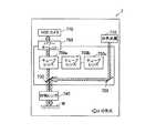
従来の光学式測定装置7においては、例えば、図7に示すように、白色光源710から出射された白色光が、ミラー720及びビームスプリッタ730を介して対物レンズ740を通過し、ワークWに照射される。ワークWに照射された白色光は、ワークWの表面で反射され、対物レンズ740及びビームスプリッタ730を介して、複数のチューブレンズ750(750a、750b、750c)のうちパワーターレット760により選択的に切り替えられた一のチューブレンズ(図中ではチューブレンズ750a)を通過し、CCDカメラ770に入射される。従来の光学式測定装置7は、上記構成を具備したことにより、ワークWの像を観察できるようになっている。 In the conventional optical measurement apparatus 7, for example, as shown in FIG. 7, white light emitted from the
ところで、近年、シリコンやフィルム等の素材に覆われた配線の観察や、ICウエハ上に形成されるソルダーレジストのような樹脂膜に覆われた配線の観察といった多種多様な観察及び測定への要望が高まっているが、上記の光学式測定装置では、照射光がワークWの表面部分(即ち、配線に到達する前)で反射されてしまうため、配線を観察することが困難であるという課題があった。 By the way, in recent years, various observation and measurement requests such as observation of wiring covered with a material such as silicon or film, and observation of wiring covered with a resin film such as a solder resist formed on an IC wafer are required. However, in the above optical measuring apparatus, the irradiation light is reflected on the surface portion of the workpiece W (that is, before reaching the wiring), so that it is difficult to observe the wiring. there were.
上記の課題に対応したものとして、例えば、近赤外観察や蛍光観察といった特殊観察を可能とした装置が知られている。
近赤外観察とは、近赤外光の性質、即ち、可視光よりも波長が長く、肉眼では見ることができない光であり、可視光とは異なり、シリコンやフィルム等の薄い素材や皮膚組織を透過する性質を利用して、近赤外光が透過する物質越しに行われる観察である。
近赤外観察の主な用途としては、シリコンやフィルム等の薄い素材を使用した回路基盤の検査、セキュリティに利用される静脈認証等が挙げられる。As a device corresponding to the above problem, for example, an apparatus capable of special observation such as near-infrared observation or fluorescence observation is known.
Near-infrared observation is the nature of near-infrared light, that is, light that has a longer wavelength than visible light and cannot be seen with the naked eye. Unlike visible light, it is a thin material such as silicon or film, or skin tissue. This observation is performed through a substance that transmits near-infrared light using the property of transmitting light.
Major applications of near-infrared observation include inspection of circuit boards using thin materials such as silicon and film, and vein authentication used for security.
従来の近赤外観察用光学式測定装置8は、図8に示すように、近赤外LED光源等の近赤外光のみを出射する特殊光源810を使用し、特殊光源810から出射された近赤外光を、ミラー820及びビームスプリッタ830を介して対物レンズ840を通過させ、ワークWに照射させる。ワークWに照射された近赤外光は、ワークWの表面を透過して図示しない配線で反射され、対物レンズ840及びビームスプリッタ830を介してチューブレンズ850を通過し、CCDカメラ860に入射される。従来の近赤外観察用光学式測定装置8は、上記構成を具備したことにより、ワークW内部の配線の像を観察できるようになっている。 As shown in FIG. 8, the conventional
一方、蛍光観察とは、ワークに対応した励起光を照射し、ワークから放射された蛍光を観察するものである。具体的には、ワークに当てた光(励起光)が、ワークの表面に形成された蛍光体の色素分子に吸収された後、蛍光体が厚みに応じて光(蛍光)を放射する現象を利用して、ワーク内部の配線を観察するものである。配線の構造により配線を覆う蛍光体の厚みが変わるため、蛍光体から放射された蛍光の強弱を観察することで、配線の構造を知ることができる。ここで、蛍光体とは、蛍光を発光する物質のことであり、多種多様な種類があるため、各蛍光体に対応する励起光、及び各蛍光体から放射される蛍光の波長も様々である。
蛍光観察の主な用途としては、ソルダーレジストが用いられたICウエハの検査、蛍光色素で染色された生物組織や細胞の観察等が挙げられる。On the other hand, fluorescence observation refers to irradiating excitation light corresponding to a workpiece and observing fluorescence emitted from the workpiece. Specifically, after the light (excitation light) applied to the workpiece is absorbed by the phosphor pigment molecules formed on the surface of the workpiece, the phosphor emits light (fluorescence) according to the thickness. This is used to observe the wiring inside the workpiece. Since the thickness of the phosphor covering the wiring changes depending on the structure of the wiring, the structure of the wiring can be known by observing the intensity of the fluorescence emitted from the phosphor. Here, the phosphor is a substance that emits fluorescence, and since there are various types, the excitation light corresponding to each phosphor and the wavelength of the fluorescence emitted from each phosphor also vary. .
Main applications of fluorescence observation include inspection of IC wafers using solder resist, observation of biological tissues and cells stained with fluorescent dyes, and the like.
従来の蛍光観察用光学式測定装置9は、図9に示すように、励起光のみを出射する特殊光源910を使用し、特殊光源910から出射された励起光の光軸上に、ワークWに対応した波長の励起光のみを透過する励起フィルタ920を設けることで、ワークWに対応した励起光を得、当該得られた励起光を、ミラー930及びダイクロイックミラー940を介して対物レンズ950を通過させ、ワークWに照射させる。励起光が照射されたワークWにおいては、ワークWの表面に形成された蛍光体から厚みに応じた蛍光が放射されるとともに、照射された励起光が反射される。ワークWからの蛍光及び励起光は、対物レンズ950及びダイクロイックミラー940を介して、蛍光のみを透過する蛍光フィルタ970を透過する。蛍光フィルタ970を透過した蛍光は、チューブレンズ960を通過し、CCDカメラ980に入射される。従来の蛍光観察用光学式測定装置9は、上記構成を具備したことにより、ワークW内部の配線の像を観察できるようになっている。 As shown in FIG. 9, the conventional optical measuring apparatus 9 for fluorescence observation uses a
しかしながら、上記の近赤外観察用光学式測定装置のように、ワークに近赤外光のみを照射する構成の場合、ワークを白色光で照明する必要がある通常の可視観察を行うことができない。
同様に、上記の蛍光観察用光学式測定装置のように、ワークに対応した励起光のみをワークに照射する構成の場合、ワークを白色光で照明する必要がある通常の可視観察を行うことができない。However, in the case where the workpiece is irradiated with only near infrared light as in the above-described optical measurement apparatus for near infrared observation, it is not possible to perform normal visible observation in which the workpiece needs to be illuminated with white light. .
Similarly, in the case of a configuration in which only the excitation light corresponding to the workpiece is irradiated onto the workpiece as in the above-described optical measurement apparatus for fluorescence observation, normal visible observation that requires the workpiece to be illuminated with white light can be performed. Can not.
本発明は、測定対象物に対して、可視観察のみならず、近赤外観察や蛍光観察といった特殊観察を行うことを可能とした光学式測定装置を提供することを目的とする。 An object of the present invention is to provide an optical measurement apparatus that can perform not only visible observation but also special observation such as near-infrared observation and fluorescence observation on a measurement object.
請求項1に記載の発明は、上記目的を達成するためになされたものであり、光学式測定装置において、測定対象物の可視観察を行う可視観察部と、
前記測定対象物の特殊観察を行う特殊観察部と、を備え、
前記可視観察部は、
白色光を出射する白色光源と、
前記白色光源と前記測定対象物との間に配され、前記白色光源から出射された白色光と、前記測定対象物からの戻り光と、を通過させる第1対物レンズと、
前記第1対物レンズを通過した前記戻り光を所定の倍率に変倍する複数のチューブレンズと、
前記複数のチューブレンズのうち前記戻り光上に配置させる一のチューブレンズを選択的に切り替え可能なレンズ切替機構と、を備え、
前記特殊観察部は、
特殊光を出射する特殊光源と、
前記特殊光源と前記測定対象物との間に配され、前記特殊光源から出射された特殊光と、前記測定対象物からの戻り光と、を通過させる第2対物レンズと、を備えることを特徴とする。Invention of Claim 1 was made | formed in order to achieve the said objective, In the optical measurement apparatus, The visual observation part which performs visual observation of a measuring object,
A special observation unit for performing special observation of the measurement object,
The visible observation part is
A white light source that emits white light;
A first objective lens that is arranged between the white light source and the measurement object and passes white light emitted from the white light source and return light from the measurement object;
A plurality of tube lenses for scaling the return light having passed through the first objective lens to a predetermined magnification;
A lens switching mechanism capable of selectively switching one tube lens arranged on the return light among the plurality of tube lenses,
The special observation part is
A special light source that emits special light;
A second objective lens that is disposed between the special light source and the measurement object and that passes special light emitted from the special light source and return light from the measurement object; And
請求項2に記載の発明は、請求項1に記載の光学式測定装置において、前記特殊光は、近赤外光であることを特徴とする。 According to a second aspect of the present invention, in the optical measurement apparatus according to the first aspect, the special light is near-infrared light.
請求項3に記載の発明は、請求項1に記載の光学式測定装置において、前記特殊光源と前記第2対物レンズとの間に配され、前記測定対象物から蛍光を放射させる波長の励起光のみを透過する励起フィルタと、
前記第2対物レンズを通過した戻り光のうち前記測定対象物から放射された蛍光のみを透過する蛍光フィルタと、を更に備え、
前記特殊光は、励起光であり、
前記第2対物レンズは、前記特殊光源から出射された励起光のうち前記励起フィルタを透過した励起光を通過させることを特徴とする。According to a third aspect of the present invention, in the optical measurement apparatus according to the first aspect, excitation light having a wavelength that is arranged between the special light source and the second objective lens and emits fluorescence from the measurement object. An excitation filter that only passes through,
A fluorescence filter that transmits only the fluorescence emitted from the measurement object among the return light that has passed through the second objective lens,
The special light is excitation light,
The second objective lens may pass the excitation light transmitted through the excitation filter out of the excitation light emitted from the special light source.
請求項4に記載の発明は、光学式測定装置において、特殊光を含む白色光を出射する白色光源と、
前記白色光源と測定対象物との間に配され、前記白色光源から出射された白色光と、前記測定対象物からの戻り光と、を通過させる対物レンズと、
前記対物レンズを通過した戻り光を所定の倍率に変倍する複数のチューブレンズと、
前記複数のチューブレンズのうち一のチューブレンズに設けられ、所定の光のみを透過する特殊フィルタと、
前記複数のチューブレンズのうち前記戻り光上に配置させる一のチューブレンズを選択的に切り替え可能なレンズ切替機構と、
前記白色光源と前記対物レンズとの間に配され、前記測定対象物から蛍光を放射させる波長の励起光のみを透過する励起フィルタを、前記白色光源から出射された白色光上に配置するか否かを選択的に切り替え可能なフィルタ切替機構と、
を備え、
前記特殊光は、励起光であり、
前記対物レンズは、前記白色光源から出射された白色光のうち前記フィルタ切替機構を通過した白色光又は励起光を通過させ、
前記特殊フィルタは、前記戻り光のうち前記測定対象物から放射された蛍光のみを透過する蛍光フィルタであることを特徴とする。According to a fourth aspect of the present invention, in the optical measurement apparatus, a white light source that emits white light including special light;
An objective lens that is arranged between the white light source and the measurement object, and passes white light emitted from the white light source and return light from the measurement object;
A plurality of tube lenses that scale the return light that has passed through the objective lens to a predetermined magnification;
A special filter that is provided in one tube lens among the plurality of tube lenses and transmits only predetermined light;
A lens switching mechanism capable of selectively switching one tube lens arranged on the return light among the plurality of tube lenses;
Whether or not an excitation filter that is disposed between the white light source and the objective lens and transmits only excitation light having a wavelength that emits fluorescence from the measurement object is disposed on the white light emitted from the white light source. A filter switching mechanism capable of selectively switching between,
Equipped witha,
The special light is excitation light,
The objective lens passes white light or excitation light that has passed through the filter switching mechanism among white light emitted from the white light source,
The special filter is characterizedfluorescence filter der Rukotowhich transmits only fluorescence emitted from the measurement object of the returning light.
請求項5に記載の発明は、請求項4に記載の光学式測定装置において、前記特殊光は、近赤外光を含み、
前記フィルタ切替機構は、前記励起フィルタ及び前記近赤外光のみを透過する近赤外光フィルタのうちいずれか一のフィルタを前記白色光源から出射された白色光上に配置するか、又は双方とも配置しないか、を選択的に切り替え可能であり、
前記対物レンズは、前記白色光源から出射された白色光のうち前記フィルタ切替機構を通過した白色光、近赤外光又は励起光を通過させることを特徴とする。The invention according to
The filter switching mechanism arranges either one of the excitation filter and the near-infrared light filter that transmits only the near-infrared light on the white light emitted from the white light source, or both. It is possible to selectively switch between not placing and
The objective lens may pass white light, near-infrared light, or excitation light that has passed through the filter switching mechanism among white light emitted from the white light source.
請求項6に記載の発明は、請求項4に記載の光学式測定装置において、前記特殊光は、近赤外光を含み、
前記複数のチューブレンズは、少なくとも3つ以上であり、前記蛍光フィルタが設けられていないチューブレンズのうち一のチューブレンズに前記近赤外光のみを透過する近赤外光フィルタが設けられていることを特徴とする。The invention according to
The plurality of tube lenses is at least three or more, and one of the tube lenses not provided with the fluorescent filter is provided with a near-infrared light filter that transmits only the near-infrared light. It is characterized by that.
本発明によれば、測定対象物の可視観察を行う可視観察部と、測定対象物の特殊観察を行う特殊観察部と、を備えるので、測定対象物に対して、可視観察のみならず、近赤外観察や蛍光観察といった特殊観察を行うことができる。 According to the present invention, a visual observation unit that performs visual observation of a measurement object and a special observation unit that performs special observation of the measurement object are provided. Special observations such as infrared observation and fluorescence observation can be performed.
以下、図を参照して、本発明に係る光学式測定装置について、詳細に説明する。本発明の光学式測定装置は、例えば、顕微鏡、画像測定機などの光学装置に搭載されるものである。 Hereinafter, an optical measuring device according to the present invention will be described in detail with reference to the drawings. The optical measuring device of the present invention is mounted on an optical device such as a microscope or an image measuring machine, for example.
(第1実施形態)
まず、構成について説明する。
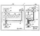
第1実施形態に係る光学式測定装置1は、図1に示すように、ワークWの可視観察を行う可視観察部100と、ワークWの蛍光観察を行う特殊観察部としての蛍光観察部200と、を備えて構成されている。(First embodiment)
First, the configuration will be described.
As shown in FIG. 1, the optical measurement apparatus 1 according to the first embodiment includes a
可視観察部100は、白色光源10と、ミラー20と、ビームスプリッタ30と、対物レンズ40と、チューブレンズ50a、50b、50cと、パワーターレット60と、CCDカメラ70と、を備えて構成されている。 The
白色光源10は、例えば、ハロゲン、放電灯、発光ダイオード等で構成され、白色光を発生させて出射する。白色光源10から出射された白色光は、白色光源10の鉛直下方に配置されたミラー20に照射される。 The
ミラー20は、白色光源10から照射された白色光を、水平方向左側に配置されたビームスプリッタ30に向かって反射させる。ミラー20により反射された白色光は、水平方向右側からビームスプリッタ30に照射される。 The
ビームスプリッタ30は、ミラー20から照射された白色光を、鉛直下方に配置された対物レンズ40に向かって反射させる。ビームスプリッタ30により反射された白色光は、鉛直上方から対物レンズ40に入射する。
また、ビームスプリッタ30は、ワークWの表面にて反射され、鉛直下方から対物レンズ40を透過して進んできた戻り光を透過する。ビームスプリッタ30を透過した戻り光は、鉛直上方に配置されたチューブレンズ50(図中ではチューブレンズ50a)に入射する。The
Further, the
対物レンズ40は、ワークWに対向するように設けられ、ビームスプリッタ30から入射した白色光を透過する。対物レンズ40を透過した白色光は、鉛直上方からワークWに向かって照射される。
また、対物レンズ40は、ワークWの表面(内面)にて反射された戻り光を透過する。対物レンズ40を透過した戻り光は、鉛直上方に配置されたビームスプリッタ30に照射される。
即ち、対物レンズ40は、白色光源10とワークWとの間に配され、白色光源10から出射された白色光と、ワークWからの戻り光と、を通過させる。The
The
In other words, the
チューブレンズ50(50a、50b、50c)は、例えば、各々倍率が異なる3つの光学レンズであり、ビームスプリッタ30から入射した戻り光上に一のチューブレンズ50(図中ではチューブレンズ50a)が配置され、当該戻り光を所定の倍率に変倍するとともに透過する。チューブレンズ50を透過した戻り光は、パワーターレット60を介して、鉛直上方に配置されたCCDカメラ70に入射する。
なお、チューブレンズ50の数は3つに限らず、2つ以上であれば任意の数とすることができる。The tube lenses 50 (50a, 50b, 50c) are, for example, three optical lenses having different magnifications, and one tube lens 50 (the
Note that the number of tube lenses 50 is not limited to three, and may be any number as long as it is two or more.
パワーターレット60は、例えば、ワークWからの戻り光と異なる位置にその戻り光と平行な軸を中心として回転可能に設けられ、かつその軸から戻り光までの距離を半径とする円周上に3つのチューブレンズ50a、50b、50cを等間隔(120度間隔)で取り付けたターレットである。
即ち、パワーターレット60は、複数のチューブレンズ50(50a、50b、50c)のうち戻り光上に配置させる一のチューブレンズ50を選択的に切り替え可能なレンズ切替機構として機能する。For example, the
That is, the
CCDカメラ70は、ワークWからの戻り光に基づいてワークWの画像を撮像し、画像データを取得する撮像素子であり、取得した画像データを、各種画像処理を行うための図示しない制御部等に出力する。 The
蛍光観察部200は、特殊光源110と、励起フィルタ120と、ミラー130と、ダイクロイックミラー140と、対物レンズ150と、チューブレンズ160と、蛍光フィルタ170と、CCDカメラ180と、を備えて構成されている。 The
特殊光源110は、例えば、ハロゲン、放電灯、発光ダイオード等で構成され、励起光を発生させて出射する。特殊光源110から出射された励起光は、特殊光源110の鉛直下方に配置された励起フィルタ120に照射される。 The special
励起フィルタ120は、ワークWから蛍光を放射させる波長の励起光のみを透過するフィルタである。
即ち、励起フィルタ120は、特殊光源110とワークWとの間に配され、特殊光源110から入射された励起光のうちワークWから蛍光を放射させる波長の励起光のみを透過し、鉛直下方に配置されたミラー130に照射させる。The
That is, the
ミラー130は、励起フィルタ120を透過した励起光を、水平方向左側に配置されたダイクロイックミラー140に向かって反射させる。ミラー130により反射された励起光は、水平方向右側からダイクロイックミラー140に照射される。 The
ダイクロイックミラー140は、ミラー130から照射された励起光を、鉛直下方に配置された対物レンズ150に向かって反射させる。ダイクロイックミラー140により反射された励起光は、鉛直上方から対物レンズ150に入射する。
また、ダイクロイックミラー140は、鉛直下方から対物レンズ150を透過して進んできた戻り光を透過する。ダイクロイックミラー140を透過した戻り光は、鉛直上方に配置された蛍光フィルタ170に照射される。The
Further, the
対物レンズ150は、ワークWに対向するように設けられ、ダイクロイックミラー140から入射した励起光を透過する。対物レンズ150を透過した励起光は、鉛直上方からワークWに向かって照射される。
また、対物レンズ150は、ワークWにて反射された励起光及びワークWに形成された蛍光体から放射された蛍光から成る戻り光を透過する。対物レンズ150を透過した戻り光は、鉛直上方に配置されたダイクロイックミラー140に照射される。
即ち、対物レンズ150は、特殊光源110とワークWとの間に配され、特殊光源110から出射された励起光のうち励起フィルタ120を透過した励起光と、ワークWからの戻り光と、を通過させる。The
Further, the
In other words, the
蛍光フィルタ170は、蛍光のみを透過するフィルタである。
即ち、蛍光フィルタ170は、ダイクロイックミラー140を透過した戻り光のうちワークWから放射された蛍光のみを透過する。The
That is, the
チューブレンズ160は、蛍光フィルタ170を透過した蛍光を所定の倍率に変倍するとともに透過する。チューブレンズ160を透過した蛍光は、鉛直上方に配置されたCCDカメラ180に入射する。 The
CCDカメラ180は、ワークWからの戻り光に基づいてワークWの画像を撮像し、画像データを取得する撮像素子であり、取得した画像データを、各種画像処理を行うための図示しない制御部等に出力する。 The
次に、作用について説明する。
光学式測定装置1では、可視観察部100において、白色光源10から出射された白色光が、ミラー20及びビームスプリッタ30を介して対物レンズ40を通過し、ワークWに照射される。ワークWに照射された白色光は、ワークWの表面で反射され、対物レンズ40及びビームスプリッタ30を介して、複数のチューブレンズ50(50a、50b、50c)のうちパワーターレット60により選択的に切り替えられた一のチューブレンズ(図中ではチューブレンズ50a)を通過し、CCDカメラ70に入射される。Next, the operation will be described.
In the optical measuring device 1, in the
また、光学式測定装置1では、蛍光観察部200において、励起光のみを出射する特殊光源110を使用し、特殊光源110から出射された励起光の光軸上に、ワークWに対応した波長の励起光のみを透過する励起フィルタ120を設けることで、ワークWに対応した励起光を得、当該得られた励起光を、ミラー130及びダイクロイックミラー140を介して対物レンズ150を通過させ、ワークWに照射させる。励起光が照射されたワークWにおいては、ワークWに形成された蛍光体から厚みに応じた蛍光が放射されるとともに、照射された励起光が反射される。ワークWからの蛍光及び励起光から成る戻り光は、対物レンズ150及びダイクロイックミラー140を介して、蛍光のみを透過する蛍光フィルタ170を透過する。蛍光フィルタ170を透過した蛍光は、チューブレンズ160を通過し、CCDカメラ180に入射される。 In the optical measurement apparatus 1, the
なお、対物レンズ40及び対物レンズ150は、一体的に水平方向に移動させることができるので、用途に応じて一方をワークWに対向させることができる。
即ち、可視観察を行う際には対物レンズ40を、蛍光観察を行う際には対物レンズ150を、ワークWに対向させる位置に移動させることで、容易に観察方法を変更することができる。In addition, since the
That is, the observation method can be easily changed by moving the
以上のように、第1実施形態に係る光学式測定装置1は、ワークWの可視観察を行う可視観察部100と、ワークWの特殊観察を行う特殊観察部(蛍光観察部200)と、を備え、可視観察部100は、白色光を出射する白色光源10と、白色光源10とワークWとの間に配され、白色光源10から出射された白色光と、ワークWからの戻り光と、を通過させる対物レンズ40と、対物レンズ40を通過した戻り光を所定の倍率に変倍する複数のチューブレンズ50(50a、50b、50c)と、複数のチューブレンズ50のうち戻り光上に配置させる一のチューブレンズ50を選択的に切り替え可能なパワーターレット60と、を備え、特殊観察部は、特殊光を出射する特殊光源110と、特殊光源110とワークWとの間に配され、特殊光源110から出射された特殊光と、ワークWからの戻り光と、を通過させる対物レンズ150と、を備える。
このため、ワークWに対して、可視観察と特殊観察を行うことができることとなって、使用者の用途に応じて容易に観察方法を変更することができる。As described above, the optical measurement apparatus 1 according to the first embodiment includes the
For this reason, visible observation and special observation can be performed on the workpiece W, and the observation method can be easily changed according to the use of the user.
特に、第1実施形態に係る光学式測定装置1は、特殊光源110と対物レンズ150との間に配され、ワークWから蛍光を放射させる波長の励起光のみを透過する励起フィルタ120と、対物レンズ150を通過した戻り光のうちワークWから放射された蛍光のみを透過する蛍光フィルタ170と、を更に備え、特殊光は、励起光であり、対物レンズ150は、特殊光源110から出射された励起光のうち励起フィルタ120を透過した励起光を通過させる。
このため、ワークWに対して、可視観察のみならず、蛍光観察を行うことができることとなって、例えば、ソルダーレジストが用いられたICウエハの検査、蛍光色素で染色された生物組織や細胞の観察等を行うことができる。In particular, the optical measurement apparatus 1 according to the first embodiment is arranged between the special
For this reason, not only visible observation but also fluorescence observation can be performed on the workpiece W. For example, inspection of an IC wafer using a solder resist, biological tissue or cells stained with a fluorescent dye, Observation can be performed.
(第2実施形態)
まず、構成について説明する。なお、説明の簡略化のため、第1実施形態と同様の構成については、同一の符号を付して、その詳細な説明を省略する。
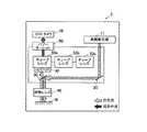
第2実施形態に係る光学式測定装置2は、図2に示すように、ワークWの可視観察を行う可視観察部100と、ワークWの近赤外観察を行う特殊観察部としての近赤外観察部300と、を備えて構成されている。(Second Embodiment)
First, the configuration will be described. For simplification of description, the same reference numerals are given to the same configurations as those in the first embodiment, and detailed description thereof is omitted.
As shown in FIG. 2, the
近赤外観察部300は、特殊光源210と、ミラー220と、ビームスプリッタ230と、対物レンズ240と、チューブレンズ250と、CCDカメラ260と、を備えて構成されている。 The near
特殊光源210は、例えば、ハロゲン、放電灯、発光ダイオード等で構成され、近赤外光を発生させて出射する。特殊光源210から出射された近赤外光は、特殊光源210の鉛直下方に配置されたミラー220に照射される。 The special
ミラー220は、特殊光源210から照射された近赤外光を、水平方向左側に配置されたビームスプリッタ230に向かって反射させる。ミラー220により反射された近赤外光は、水平方向右側からビームスプリッタ230に照射される。 The
ビームスプリッタ230は、ミラー220から照射された近赤外光を、鉛直下方に配置された対物レンズ240に向かって反射させる。ビームスプリッタ230により反射された近赤外光は、鉛直上方から対物レンズ240に入射する。
また、ビームスプリッタ230は、ワークWの表面を透過して図示しない配線で反射され、鉛直下方から対物レンズ240を透過して進んできた戻り光を透過する。ビームスプリッタ230を透過した戻り光は、鉛直上方に配置されたチューブレンズ250に入射する。The
The
対物レンズ240は、ワークWに対向するように設けられ、ビームスプリッタ230から入射した近赤外光を透過する。対物レンズ240を透過した近赤外光は、鉛直上方からワークWに向かって照射される。
また、対物レンズ240は、ワークWの表面を透過して図示しない配線で反射された戻り光を透過する。対物レンズ240を透過した戻り光は、鉛直上方に配置されたビームスプリッタ230に照射される。
即ち、対物レンズ240は、特殊光源210とワークWとの間に配され、特殊光源210から出射された近赤外光と、ワークWからの戻り光と、を通過させる。The
The
That is, the
チューブレンズ250は、ビームスプリッタ230から入射した戻り光を所定の倍率に変倍するとともに透過する。チューブレンズ250を透過した戻り光は、鉛直上方に配置されたCCDカメラ260に入射する。 The
CCDカメラ260は、ワークWからの戻り光に基づいてワークWの画像を撮像し、画像データを取得する撮像素子であり、取得した画像データを、各種画像処理を行うための図示しない制御部等に出力する。 The
次に、作用について説明する。
光学式測定装置2では、可視観察部100において、白色光源10から出射された白色光が、ミラー20及びビームスプリッタ30を介して対物レンズ40を通過し、ワークWに照射される。ワークWに照射された白色光は、ワークWの表面で反射され、対物レンズ40及びビームスプリッタ30を介して、複数のチューブレンズ50(50a、50b、50c)のうちパワーターレット60により選択的に切り替えられた一のチューブレンズ(図中ではチューブレンズ50a)を通過し、CCDカメラ70に入射される。Next, the operation will be described.
In the
また、光学式測定装置2では、近赤外観察部300において、近赤外光のみを出射する特殊光源210を使用し、特殊光源210から出射された近赤外光を、ミラー220及びビームスプリッタ230を介して対物レンズ240を通過させ、ワークWに照射させる。ワークWに照射された近赤外光は、ワークWの表面を透過して図示しない配線で反射され、対物レンズ240及びビームスプリッタ230を介してチューブレンズ250を通過し、CCDカメラ260に入射される。 In the
なお、対物レンズ40及び対物レンズ240は、一体的に水平方向に移動させることができるので、用途に応じて一方をワークWに対向させることができる。
即ち、可視観察を行う際には対物レンズ40を、近赤外観察を行う際には対物レンズ240を、ワークWに対向させる位置に移動させることで、容易に観察方法を変更することができる。In addition, since the
That is, the observation method can be easily changed by moving the
以上のように、第2実施形態に係る光学式測定装置2は、特殊光源210として近赤外光を出射する光源を使用しているので、可視観察部100における可視観察のみならず、特殊観察部(近赤外観察部300)における近赤外観察を行うことができることとなって、例えば、シリコンやフィルム等の薄い素材を使用した回路基盤の検査、セキュリティに利用される静脈認証等を行うことができる。 As described above, the
(第3実施形態)
まず、構成について説明する。なお、説明の簡略化のため、第1、第2実施形態と同様の構成については、同一の符号を付して、その詳細な説明を省略する。
第3実施形態に係る光学式測定装置3は、図3に示すように、高輝度光源11と、ミラー20と、ビームスプリッタ30と、対物レンズ40と、チューブレンズ50a、50b、50cと、ハイパスフィルタ80と、パワーターレット60と、CCDカメラ70と、を備えて構成されている。(Third embodiment)
First, the configuration will be described. For simplification of description, the same reference numerals are given to the same configurations as those in the first and second embodiments, and detailed description thereof is omitted.
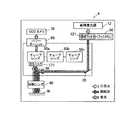
As shown in FIG. 3, the optical measurement device 3 according to the third embodiment includes a high-
高輝度光源11は、例えば、ハロゲン、放電灯、発光ダイオード等で構成される広帯域の光源であり、近赤外光を含む高輝度の白色光を発生させて出射する。高輝度光源11から出射された白色光は、高輝度光源11の鉛直下方に配置されたミラー20に照射される。 The high-
ハイパスフィルタ80は、近赤外光のみを透過するフィルタである。
即ち、ハイパスフィルタ80は、ビームスプリッタ30を透過した戻り光(近赤外光を含む白色光)のうち近赤外光のみを透過する。
このハイパスフィルタ80は、複数のチューブレンズ50(50a、50b、50c)のうち一のチューブレンズ50(図中ではチューブレンズ50a)と一体となるように設けられており、パワーターレット60によるチューブレンズ50の切替操作に付随して移動するようになっている。The
That is, the high-
The high-
次に、作用について説明する。
光学式測定装置3では、高輝度光源11から出射された近赤外光を含む高輝度の白色光が、ミラー20及びビームスプリッタ30を介して対物レンズ40を通過し、ワークWに照射される。ワークWに照射された白色光に含まれる近赤外光は、ワークWの表面を透過して図示しない配線で反射される。ワークWからの戻り光は、対物レンズ40及びビームスプリッタ30を介して、近赤外光のみを透過するハイパスフィルタ80を透過する。ハイパスフィルタ80を透過した近赤外光は、チューブレンズ50aを通過し、CCDカメラ70に照射される。Next, the operation will be described.
In the optical measurement device 3, high-intensity white light including near-infrared light emitted from the high-
一方、パワーターレット60によるチューブレンズ50の切替操作により、ハイパスフィルタ80が設けられていないチューブレンズ50(例えばチューブレンズ50b)を戻り光上に配置させた場合、戻り光上にハイパスフィルタ80が存在しないこととなるため、ワークWからの戻り光は、そのままチューブレンズ50bを通過してCCDカメラ70に入射される。 On the other hand, when the tube lens 50 (for example, the
以上のように、第3実施形態に係る光学式測定装置3は、特殊光を含む白色光を出射する白色光源(高輝度光源11)と、高輝度光源11とワークWとの間に配され、高輝度光源11から出射された白色光と、ワークWからの戻り光と、を通過させる対物レンズ40と、対物レンズ40を通過した戻り光を所定の倍率に変倍する複数のチューブレンズ50(50a、50b、50c)と、複数のチューブレンズ50のうち一のチューブレンズ50(例えば、チューブレンズ50a)に設けられ、所定の光のみを透過する特殊フィルタ(ハイパスフィルタ80)と、複数のチューブレンズ50のうち戻り光上に配置させる一のチューブレンズ50を選択的に切り替え可能なパワーターレット60と、を備える。
このため、パワーターレット60によるチューブレンズ50の切替操作により、ワークWからの戻り光上に特殊フィルタを配置するか否かを選択することができることとなって、使用者は容易に可視観察と特殊観察とを切り替えることができる。As described above, the optical measurement device 3 according to the third embodiment is arranged between the white light source (high luminance light source 11) that emits white light including special light, and the high
For this reason, by switching the tube lens 50 with the
特に、第3実施形態に係る光学式測定装置3は、白色光源として近赤外光を含む白色光を出射する光源を、特殊フィルタとして近赤外光のみを透過するハイパスフィルタ80を、それぞれ使用しているので、パワーターレット60によるチューブレンズ50の切替操作により、可視観察のみならず、近赤外観察を行うことができることとなって、例えば、シリコンやフィルム等の薄い素材を使用した回路基盤の検査、セキュリティに利用される静脈認証等を行うことができる。 In particular, the optical measuring device 3 according to the third embodiment uses a light source that emits white light including near infrared light as a white light source, and a high-
(第4実施形態)
まず、構成について説明する。なお、説明の簡略化のため、第1〜3実施形態と同様の構成については、同一の符号を付して、その詳細な説明を省略する。
第4実施形態に係る光学式測定装置4は、図4に示すように、高輝度光源12と、フィルタ切替ターレット90と、ミラー20と、ビームスプリッタ30と、対物レンズ40と、チューブレンズ50a、50b、50cと、蛍光フィルタ171と、パワーターレット60と、CCDカメラ70と、を備えて構成されている。(Fourth embodiment)
First, the configuration will be described. For simplification of description, the same reference numerals are given to the same configurations as those in the first to third embodiments, and detailed description thereof is omitted.
As shown in FIG. 4, the
高輝度光源12は、例えば、ハロゲン、放電灯、発光ダイオード等で構成される広帯域の光源であり、励起光を含む高輝度の白色光を発生させて出射する。高輝度光源12から出射された白色光は、高輝度光源12の鉛直下方に配置されたフィルタ切替ターレット90に照射される。 The high-
フィルタ切替ターレット90は、高輝度光源12から出射された白色光上に、ワークWから蛍光を放射させる波長の励起光のみを透過する励起フィルタ121を配置するか否かを選択的に切り替え可能なターレットであり、フィルタ切替機構として機能する。 The
蛍光フィルタ171は、蛍光のみを透過するフィルタである。
即ち、蛍光フィルタ171は、ビームスプリッタ30を透過した戻り光のうちワークWから放射された蛍光のみを透過する。
この蛍光フィルタ171は、複数のチューブレンズ50(50a、50b、50c)のうち一のチューブレンズ50(図中ではチューブレンズ50a)と一体となるように設けられており、パワーターレット60によるチューブレンズ50の切替操作に付随して移動するようになっている。The
In other words, the
The
次に、作用について説明する。
光学式測定装置4は、高輝度光源12から出射された白色光上に励起フィルタ121を配置するか否かを選択的に切り替え可能なフィルタ切替ターレット90を設けている。
このフィルタ切替ターレット90を操作して白色光上に励起フィルタ121を配置し、かつパワーターレット60を操作して蛍光フィルタ171が設けられたチューブレンズ50aを戻り光上に配置させた場合(図4参照)、励起フィルタ121を透過したことで得られた励起光が、ミラー20及びビームスプリッタ30を介して対物レンズ40を通過し、ワークWに照射される。励起光が照射されたワークWにおいては、ワークWに形成された蛍光体から厚みに応じた蛍光が放射されるとともに、照射された励起光が反射される。ワークWからの蛍光及び励起光から成る戻り光は、対物レンズ40及びビームスプリッタ30を介して、蛍光のみを透過する蛍光フィルタ171を透過する。蛍光フィルタ171を透過した蛍光は、チューブレンズ50aを通過し、CCDカメラ70に入射される。Next, the operation will be described.
The
When the
一方、フィルタ切替ターレット90を操作して白色光上に励起フィルタ121を配置しない状態とし、かつパワーターレット60を操作して蛍光フィルタ171が設けられていないチューブレンズ50(例えばチューブレンズ50b)を戻り光上に配置させた場合、ワークWに対して高輝度光源12から出射された白色光がそのまま照射されるうえ、ワークWからの戻り光上に蛍光フィルタ171が存在しないこととなるため、ワークWからの戻り光は、そのままチューブレンズ50bを通過してCCDカメラ70に入射される。 On the other hand, the
以上のように、第4実施形態に係る光学式測定装置4は、白色光源(高輝度光源12)と対物レンズ40との間に配され、ワークWから蛍光を放射させる波長の励起光のみを透過する励起フィルタ121を、高輝度光源12から出射された白色光上に配置するか否かを選択的に切り替え可能なフィルタ切替ターレット90を更に備え、白色光源として励起光を含む白色光を出射する光源を、特殊フィルタとして戻り光のうちワークWから放射された蛍光のみを透過する蛍光フィルタ171を、それぞれ使用し、対物レンズ40は、高輝度光源12から出射された白色光のうちフィルタ切替ターレット90を通過した白色光又は励起光を通過させる。
このため、フィルタ切替ターレット90による励起フィルタ121の切替操作及びパワーターレット60によるチューブレンズ50の切替操作により、可視観察のみならず、蛍光観察を行うことができることとなって、例えば、ソルダーレジストが用いられたICウエハの検査、蛍光色素で染色された生物組織や細胞の観察等を行うことができる。As described above, the
For this reason, not only visible observation but also fluorescence observation can be performed by the switching operation of the
(第5実施形態)
まず、構成について説明する。なお、説明の簡略化のため、第1〜4実施形態と同様の構成については、同一の符号を付して、その詳細な説明を省略する。
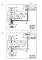
第5実施形態に係る光学式測定装置5は、図5(a)、(b)に示すように、高輝度光源13と、フィルタ切替ターレット91と、ミラー20と、ビームスプリッタ30と、対物レンズ40と、チューブレンズ50a、50b、50cと、蛍光フィルタ171と、パワーターレット60と、CCDカメラ70と、を備えて構成されている。(Fifth embodiment)
First, the configuration will be described. For simplification of description, the same reference numerals are given to the same configurations as those in the first to fourth embodiments, and detailed description thereof is omitted.
As shown in FIGS. 5A and 5B, the
高輝度光源13は、例えば、ハロゲン、放電灯、発光ダイオード等で構成される広帯域の光源であり、近赤外光及び励起光を含む高輝度の白色光を発生させて出射する。高輝度光源13から出射された白色光は、高輝度光源13の鉛直下方に配置されたフィルタ切替ターレット91に照射される。 The high-
フィルタ切替ターレット91は、高輝度光源13から出射された白色光上に、ワークWから蛍光を放射させる波長の励起光のみを透過する励起フィルタ121及び近赤外光のみを透過するハイパスフィルタ81のうちいずれか一のフィルタを配置するか、又は双方とも配置しないか、を選択的に切り替え可能なターレットであり、フィルタ切替機構として機能する。 The
次に、作用について説明する。
光学式測定装置5は、高輝度光源13から出射された白色光上に、励起フィルタ121及びハイパスフィルタ81のうちいずれか一のフィルタを配置するか、又は双方とも配置しないか、を選択的に切り替え可能なフィルタ切替ターレット91を設けている。
このフィルタ切替ターレット91を操作して白色光上に励起フィルタ121を配置し、かつパワーターレット60を操作して蛍光フィルタ171が設けられたチューブレンズ50aを戻り光上に配置させた場合(図5(a)参照)、励起フィルタ121を透過したことで得られた励起光が、ミラー20及びビームスプリッタ30を介して対物レンズ40を通過し、ワークWに照射される。励起光が照射されたワークWにおいては、ワークWに形成された蛍光体から厚みに応じた蛍光が放射されるとともに、照射された励起光が反射される。ワークWからの蛍光及び励起光から成る戻り光は、対物レンズ40及びビームスプリッタ30を介して、蛍光のみを透過する蛍光フィルタ171を透過する。蛍光フィルタ171を透過した蛍光は、チューブレンズ50aを通過し、CCDカメラ70に入射される。Next, the operation will be described.
The
When the
また、フィルタ切替ターレット91を操作して白色光上にハイパスフィルタ81を配置し、かつパワーターレット60を操作して蛍光フィルタ171が設けられていないチューブレンズ50(例えばチューブレンズ50b)を戻り光上に配置させた場合(図5(b)参照)、ハイパスフィルタ81を透過したことで得られた近赤外光が、ミラー20及びビームスプリッタ30を介して対物レンズ40を通過し、ワークWに照射される。ワークWに照射された近赤外光は、ワークWの表面を透過して図示しない配線で反射され、対物レンズ40及びビームスプリッタ30を介して、チューブレンズ50bを通過し、CCDカメラ70に入射される。 Further, the high-
一方、フィルタ切替ターレット91を操作して白色光上に励起フィルタ121及びハイパスフィルタ81を配置しない状態とし、かつパワーターレット60を操作して蛍光フィルタ171が設けられていないチューブレンズ50(例えばチューブレンズ50b)を戻り光上に配置させた場合、ワークWに対して高輝度光源13から出射された白色光がそのまま照射されるうえ、ワークWからの戻り光上に蛍光フィルタ171が存在しないこととなるため、ワークWからの戻り光は、そのままチューブレンズ50bを通過してCCDカメラ70に入射される。 On the other hand, the tube lens 50 (for example, a tube lens) in which the
第5実施形態に係る光学式測定装置5は、白色光源(高輝度光源13)として励起光及び近赤外光を含む白色光を出射する光源を使用し、フィルタ切替ターレット91は、励起フィルタ121及び近赤外光のみを透過するハイパスフィルタ81のうちいずれか一のフィルタを高輝度光源13から出射された白色光上に配置するか、又は双方とも配置しないか、を選択的に切り替え可能であり、対物レンズ40は、高輝度光源13から出射された白色光のうちフィルタ切替ターレット91を通過した白色光、近赤外光又は励起光を通過させる。
このため、フィルタ切替ターレット91によるフィルタの切替操作及びパワーターレット60によるチューブレンズ50の切替操作により、可視観察のみならず、蛍光観察や近赤外観察を行うことができることとなって、例えば、ソルダーレジストが用いられたICウエハの検査、蛍光色素で染色された生物組織や細胞の観察や、シリコンやフィルム等の薄い素材を使用した回路基盤の検査、セキュリティに利用される静脈認証等を行うことができる。The
For this reason, not only visible observation but also fluorescence observation and near-infrared observation can be performed by the switching operation of the filter by the
(第5実施形態の変形例)
まず、構成について説明する。なお、説明の簡略化のため、第1〜5実施形態と同様の構成については、同一の符号を付して、その詳細な説明を省略する。
第5実施形態の変形例に係る光学式測定装置6は、図6(a)、(b)に示すように、高輝度光源13と、フィルタ切替ターレット90と、ミラー20と、ビームスプリッタ30と、対物レンズ40と、チューブレンズ50a、50b、50cと、蛍光フィルタ171と、ハイパスフィルタ80と、パワーターレット60と、CCDカメラ70と、を備えて構成されている。(Modification of the fifth embodiment)
First, the configuration will be described. For simplification of description, the same reference numerals are given to the same configurations as those in the first to fifth embodiments, and detailed description thereof is omitted.
As shown in FIGS. 6A and 6B, the
即ち、第5実施形態と比較し、ハイパスフィルタ80を、フィルタ切替ターレット90内ではなく、チューブレンズ50bに設けた点において異なる。 That is, it differs from the fifth embodiment in that the high-
次に、作用について説明する。
光学式測定装置6は、高輝度光源13から出射された白色光上に励起フィルタ121を配置するか否かを選択的に切り替え可能なフィルタ切替ターレット90を設けている。
このフィルタ切替ターレット90を操作して白色光上に励起フィルタ121を配置し、かつパワーターレット60を操作して蛍光フィルタ171が設けられたチューブレンズ50aを戻り光上に配置させた場合(図6(a)参照)、励起フィルタ121を透過したことで得られた励起光が、ミラー20及びビームスプリッタ30を介して対物レンズ40を通過し、ワークWに照射される。励起光が照射されたワークWにおいては、ワークWに形成された蛍光体から厚みに応じた蛍光が放射されるとともに、照射された励起光が反射される。ワークWからの蛍光及び励起光から成る戻り光は、対物レンズ40及びビームスプリッタ30を介して、蛍光のみを透過する蛍光フィルタ171を透過する。蛍光フィルタ171を透過した蛍光は、チューブレンズ50aを通過し、CCDカメラ70に入射される。Next, the operation will be described.
The
When the
また、フィルタ切替ターレット90を操作して白色光上に励起フィルタ121を配置しない状態とし、かつパワーターレット60を操作してハイパスフィルタ80が設けられたチューブレンズ50bを戻り光上に配置させた場合(図6(b)参照)、高輝度光源13から出射された近赤外光を含む高輝度の白色光が、ミラー20及びビームスプリッタ30を介して対物レンズ40を通過し、ワークWに照射される。ワークWに照射された白色光に含まれる近赤外光は、ワークWの表面を透過して図示しない配線で反射される。ワークWからの戻り光は、対物レンズ40及びビームスプリッタ30を介して、近赤外光のみを透過するハイパスフィルタ80を透過する。ハイパスフィルタ80を透過した近赤外光は、チューブレンズ50bを通過し、CCDカメラ70に入射される。 Further, when the
一方、フィルタ切替ターレット90を操作して白色光上に励起フィルタ121を配置しない状態とし、かつパワーターレット60を操作して蛍光フィルタ171及びハイパスフィルタ80が設けられていないチューブレンズ50(例えばチューブレンズ50c)を戻り光上に配置させた場合、ワークWに対して高輝度光源13から出射された白色光がそのまま照射されるうえ、ワークWからの戻り光上に蛍光フィルタ171及びハイパスフィルタ80が存在しないこととなるため、ワークWからの戻り光は、そのままチューブレンズ50cを通過してCCDカメラ70に入射される。 On the other hand, a tube lens 50 (for example, a tube lens) in which the
第5実施形態の変形例に係る光学式測定装置6は、白色光源(高輝度光源13)として励起光及び近赤外光を含む白色光を出射する光源を使用し、複数のチューブレンズ50は、少なくとも3つ以上であり、蛍光フィルタ171が設けられていないチューブレンズ50のうち一のチューブレンズ50(例えば、チューブレンズ50b)に近赤外光のみを透過するハイパスフィルタ80が設けられている。
このため、フィルタ切替ターレット90による励起フィルタ121の切替操作及びパワーターレット60によるチューブレンズ50の切替操作により、可視観察のみならず、蛍光観察や近赤外観察を行うことができることとなって、例えば、ソルダーレジストが用いられたICウエハの検査、蛍光色素で染色された生物組織や細胞の観察や、シリコンやフィルム等の薄い素材を使用した回路基盤の検査、セキュリティに利用される静脈認証等を行うことができる。The
For this reason, not only visible observation but also fluorescence observation and near infrared observation can be performed by the switching operation of the
以上、本発明に係る実施形態に基づいて具体的に説明したが、本発明は上記実施形態に限定されるものではなく、その要旨を逸脱しない範囲で変更可能である。 As mentioned above, although concretely demonstrated based on embodiment which concerns on this invention, this invention is not limited to the said embodiment, It can change in the range which does not deviate from the summary.
例えば、上記実施形態では、蛍光フィルタやハイパスフィルタをチューブレンズと対物レンズの間に設けるようにしているが、これに限定されるものではなく、例えば、チューブレンズとCCDカメラの間に設けるようにしてもよい。 For example, in the above embodiment, the fluorescent filter and the high-pass filter are provided between the tube lens and the objective lens. However, the present invention is not limited to this. For example, the fluorescent filter or the high-pass filter is provided between the tube lens and the CCD camera. May be.
その他、光学式測定装置を構成する各装置の細部構成及び細部動作に関しても、本発明の趣旨を逸脱することのない範囲で適宜変更可能である In addition, the detailed configuration and detailed operation of each apparatus constituting the optical measurement apparatus can be changed as appropriate without departing from the spirit of the present invention.
1〜6 光学式測定装置
100 可視観察部
200 蛍光観察部(特殊観察部)
300 近赤外観察部(特殊観察部)
10 白色光源
11、12、13 高輝度光源(白色光源)
20、130、220 ミラー
30、230 ビームスプリッタ
40 対物レンズ(第1対物レンズ)
50(50a、50b、50c)、160、250 チューブレンズ
60 パワーターレット(レンズ切替機構)
70、180、260 CCDカメラ
80 ハイパスフィルタ(近赤外光フィルタ;特殊フィルタ)
90、91 フィルタ切替ターレット(フィルタ切替機構)
110、210 特殊光源
120、121 励起フィルタ
140 ダイクロイックミラー
150、240 対物レンズ(第2対物レンズ)
170、171 蛍光フィルタ(特殊フィルタ)1-6
300 Near-infrared observation part (special observation part)
10
20, 130, 220
50 (50a, 50b, 50c), 160, 250
70, 180, 260
90, 91 Filter switching turret (filter switching mechanism)
110, 210 Special
170, 171 Fluorescent filter (special filter)
Claims (6)
Translated fromJapanese前記測定対象物の特殊観察を行う特殊観察部と、を備え、
前記可視観察部は、
白色光を出射する白色光源と、
前記白色光源と前記測定対象物との間に配され、前記白色光源から出射された白色光と、前記測定対象物からの戻り光と、を通過させる第1対物レンズと、
前記第1対物レンズを通過した前記戻り光を所定の倍率に変倍する複数のチューブレンズと、
前記複数のチューブレンズのうち前記戻り光上に配置させる一のチューブレンズを選択的に切り替え可能なレンズ切替機構と、を備え、
前記特殊観察部は、
特殊光を出射する特殊光源と、
前記特殊光源と前記測定対象物との間に配され、前記特殊光源から出射された特殊光と、前記測定対象物からの戻り光と、を通過させる第2対物レンズと、を備えることを特徴とする光学式測定装置。A visual observation unit for visual observation of the measurement object;
A special observation unit for performing special observation of the measurement object,
The visible observation part is
A white light source that emits white light;
A first objective lens that is arranged between the white light source and the measurement object and passes white light emitted from the white light source and return light from the measurement object;
A plurality of tube lenses for scaling the return light having passed through the first objective lens to a predetermined magnification;
A lens switching mechanism capable of selectively switching one tube lens arranged on the return light among the plurality of tube lenses,
The special observation part is
A special light source that emits special light;
A second objective lens that is disposed between the special light source and the measurement object and that passes special light emitted from the special light source and return light from the measurement object; An optical measuring device.
前記第2対物レンズを通過した戻り光のうち前記測定対象物から放射された蛍光のみを透過する蛍光フィルタと、を更に備え、
前記特殊光は、励起光であり、
前記第2対物レンズは、前記特殊光源から出射された励起光のうち前記励起フィルタを透過した励起光を通過させることを特徴とする請求項1に記載の光学式測定装置。An excitation filter that is disposed between the special light source and the second objective lens and transmits only excitation light having a wavelength for emitting fluorescence from the measurement object;
A fluorescence filter that transmits only the fluorescence emitted from the measurement object among the return light that has passed through the second objective lens,
The special light is excitation light,
2. The optical measurement apparatus according to claim 1, wherein the second objective lens passes excitation light transmitted through the excitation filter among excitation light emitted from the special light source.
前記白色光源と測定対象物との間に配され、前記白色光源から出射された白色光と、前記測定対象物からの戻り光と、を通過させる対物レンズと、
前記対物レンズを通過した戻り光を所定の倍率に変倍する複数のチューブレンズと、
前記複数のチューブレンズのうち一のチューブレンズに設けられ、所定の光のみを透過する特殊フィルタと、
前記複数のチューブレンズのうち前記戻り光上に配置させる一のチューブレンズを選択的に切り替え可能なレンズ切替機構と、
前記白色光源と前記対物レンズとの間に配され、前記測定対象物から蛍光を放射させる波長の励起光のみを透過する励起フィルタを、前記白色光源から出射された白色光上に配置するか否かを選択的に切り替え可能なフィルタ切替機構と、
を備え、
前記特殊光は、励起光であり、
前記対物レンズは、前記白色光源から出射された白色光のうち前記フィルタ切替機構を通過した白色光又は励起光を通過させ、
前記特殊フィルタは、前記戻り光のうち前記測定対象物から放射された蛍光のみを透過する蛍光フィルタであることを特徴とする光学式測定装置。A white light source that emits white light including special light;
An objective lens that is arranged between the white light source and the measurement object, and passes white light emitted from the white light source and return light from the measurement object;
A plurality of tube lenses that scale the return light that has passed through the objective lens to a predetermined magnification;
A special filter that is provided in one tube lens among the plurality of tube lenses and transmits only predetermined light;
A lens switching mechanism capable of selectively switching one tube lens arranged on the return light among the plurality of tube lenses;
Whether or not an excitation filter that is disposed between the white light source and the objective lens and transmits only excitation light having a wavelength that emits fluorescence from the measurement object is disposed on the white light emitted from the white light source. A filter switching mechanism capable of selectively switching between,
Equipped witha,
The special light is excitation light,
The objective lens passes white light or excitation light that has passed through the filter switching mechanism among white light emitted from the white light source,
The special filter, an optical measuring device according to claimfluorescence filter der Rukotowhich transmits only fluorescence emitted from the measurement object of the returning light.
前記フィルタ切替機構は、前記励起フィルタ及び前記近赤外光のみを透過する近赤外光フィルタのうちいずれか一のフィルタを前記白色光源から出射された白色光上に配置するか、又は双方とも配置しないか、を選択的に切り替え可能であり、
前記対物レンズは、前記白色光源から出射された白色光のうち前記フィルタ切替機構を通過した白色光、近赤外光又は励起光を通過させることを特徴とする請求項4に記載の光学式測定装置。The special light includes near infrared light,
The filter switching mechanism arranges either one of the excitation filter and the near-infrared light filter that transmits only the near-infrared light on the white light emitted from the white light source, or both. It is possible to selectively switch between not placing and
The optical measurement according to claim4 , wherein the objective lens passes white light, near infrared light, or excitation light that has passed through the filter switching mechanism among white light emitted from the white light source. apparatus.
前記複数のチューブレンズは、少なくとも3つ以上であり、前記蛍光フィルタが設けられていないチューブレンズのうち一のチューブレンズに前記近赤外光のみを透過する近赤外光フィルタが設けられていることを特徴とする請求項4に記載の光学式測定装置。The special light includes near infrared light,
The plurality of tube lenses is at least three or more, and one of the tube lenses not provided with the fluorescent filter is provided with a near-infrared light filter that transmits only the near-infrared light. The optical measuring device according to claim4 .
Priority Applications (6)
| Application Number | Priority Date | Filing Date | Title |
|---|---|---|---|
| JP2010281102AJP5570963B2 (en) | 2010-12-17 | 2010-12-17 | Optical measuring device |
| US13/305,038US9006657B2 (en) | 2010-12-17 | 2011-11-28 | Optical measuring device |
| KR20110135683AKR101441441B1 (en) | 2010-12-17 | 2011-12-15 | Optical measuring device |
| EP20110194131EP2466293B1 (en) | 2010-12-17 | 2011-12-16 | Optical measuring device |
| CN201110423282.2ACN102539432B (en) | 2010-12-17 | 2011-12-16 | Optical measuring device |
| US14/167,562US9170196B2 (en) | 2010-12-17 | 2014-01-29 | Optical measuring device |
Applications Claiming Priority (1)
| Application Number | Priority Date | Filing Date | Title |
|---|---|---|---|
| JP2010281102AJP5570963B2 (en) | 2010-12-17 | 2010-12-17 | Optical measuring device |
Publications (2)
| Publication Number | Publication Date |
|---|---|
| JP2012128295A JP2012128295A (en) | 2012-07-05 |
| JP5570963B2true JP5570963B2 (en) | 2014-08-13 |
Family
ID=45442870
Family Applications (1)
| Application Number | Title | Priority Date | Filing Date |
|---|---|---|---|
| JP2010281102AActiveJP5570963B2 (en) | 2010-12-17 | 2010-12-17 | Optical measuring device |
Country Status (5)
| Country | Link |
|---|---|
| US (2) | US9006657B2 (en) |
| EP (1) | EP2466293B1 (en) |
| JP (1) | JP5570963B2 (en) |
| KR (1) | KR101441441B1 (en) |
| CN (1) | CN102539432B (en) |
Families Citing this family (11)
| Publication number | Priority date | Publication date | Assignee | Title |
|---|---|---|---|---|
| CN104378538A (en)* | 2014-11-27 | 2015-02-25 | 杭州艾比希科技有限公司 | Intelligent-capture dimming camera |
| CN104713850B (en)* | 2015-02-09 | 2017-06-23 | 上海安允科技有限公司 | It is inflammable and explosive to wait the motor-driven carrying detection means of gas hazard scene |
| WO2016157416A1 (en)* | 2015-03-31 | 2016-10-06 | 公立大学法人大阪市立大学 | Endoscope, attachment for endoscope, and endoscope system |
| CN105487218B (en)* | 2015-12-28 | 2019-02-19 | 宁波舜宇仪器有限公司 | Micro- scanner and micro- scan method |
| JP6746376B2 (en)* | 2016-05-23 | 2020-08-26 | 株式会社ミツトヨ | Switching method of measurement system and setting value for adjustment |
| CN110031411A (en)* | 2019-04-17 | 2019-07-19 | 南京邮电大学 | A kind of spectrum imaging system |
| DE102019117858B3 (en) | 2019-07-02 | 2020-07-02 | diemietwaesche.de gmbh + co. kg | Test device and method for testing the retroreflection and / or fluorescence of an object |
| CN112629827A (en)* | 2019-09-24 | 2021-04-09 | 成都辰显光电有限公司 | LED chip detection device and LED chip detection method |
| JP7699755B2 (en)* | 2021-01-13 | 2025-06-30 | 住友ゴム工業株式会社 | Topping rubber sheet rubber attachment defect detection device |
| KR102549436B1 (en)* | 2021-04-01 | 2023-06-30 | 롭틱스(주) | Semiconductor circuit pattern inspection device using reflected light and fluorescence |
| KR102712716B1 (en)* | 2021-11-05 | 2024-10-02 | 주식회사 위브 | Inspection device using both white light and excitation light |
Family Cites Families (16)
| Publication number | Priority date | Publication date | Assignee | Title |
|---|---|---|---|---|
| DE4245060B4 (en) | 1992-09-19 | 2007-12-06 | Leica Microsystems Cms Gmbh | Modular microscope system |
| US5590660A (en) | 1994-03-28 | 1997-01-07 | Xillix Technologies Corp. | Apparatus and method for imaging diseased tissue using integrated autofluorescence |
| JP3363703B2 (en) | 1996-05-16 | 2003-01-08 | 株式会社ミツトヨ | Optical measuring device |
| US6650357B1 (en) | 1997-04-09 | 2003-11-18 | Richardson Technologies, Inc. | Color translating UV microscope |
| EP1403675B1 (en) | 1997-04-09 | 2006-06-14 | 1192062 Alberta Limited | Colour translating UV microscope |
| US6400395B1 (en) | 1999-09-08 | 2002-06-04 | Rex A. Hoover | Computerized video microscopy system |
| JP4642178B2 (en)* | 2000-01-18 | 2011-03-02 | オリンパス株式会社 | Infrared microscope and observation tube used therefor |
| EP1207387A1 (en) | 2000-11-20 | 2002-05-22 | Institut Curie | Multi-photon imaging installation. |
| KR100411631B1 (en) | 2001-10-18 | 2003-12-18 | 주식회사 메디미르 | Fluorescence endoscope apparatus and a method for imaging tissue within a body using the same |
| US7075714B2 (en)* | 2002-02-26 | 2006-07-11 | Olympus Corporation | Anti-reflection film and microscope having optical element with the same anti-reflection film applied thereto |
| CN100557419C (en) | 2005-07-12 | 2009-11-04 | 东华大学 | Fluorescence detection optical device with microflow control chip |
| DE102005054184B4 (en)* | 2005-11-14 | 2020-10-29 | Carl Zeiss Microscopy Gmbh | Multispectral lighting device and measuring method |
| CN101401722B (en) | 2008-11-07 | 2012-07-25 | 上海奥通激光技术有限公司 | Multi-mode co-focusing imaging method and apparatus |
| JP5189966B2 (en) | 2008-11-28 | 2013-04-24 | 株式会社ミツトヨ | Autofocus device |
| JP2010190776A (en)* | 2009-02-19 | 2010-09-02 | Nikon Corp | Imaging device and surface inspection device |
| EP2615967B1 (en)* | 2010-09-17 | 2017-08-16 | LLtech Management | Optical tissue sectioning using full field optical coherence tomography |
- 2010
- 2010-12-17JPJP2010281102Apatent/JP5570963B2/enactiveActive
- 2011
- 2011-11-28USUS13/305,038patent/US9006657B2/enactiveActive
- 2011-12-15KRKR20110135683Apatent/KR101441441B1/enactiveActive
- 2011-12-16EPEP20110194131patent/EP2466293B1/enactiveActive
- 2011-12-16CNCN201110423282.2Apatent/CN102539432B/enactiveActive
- 2014
- 2014-01-29USUS14/167,562patent/US9170196B2/enactiveActive
Also Published As
| Publication number | Publication date |
|---|---|
| CN102539432B (en) | 2015-04-29 |
| EP2466293B1 (en) | 2014-02-12 |
| KR101441441B1 (en) | 2014-09-17 |
| US9170196B2 (en) | 2015-10-27 |
| US20140145084A1 (en) | 2014-05-29 |
| US9006657B2 (en) | 2015-04-14 |
| JP2012128295A (en) | 2012-07-05 |
| CN102539432A (en) | 2012-07-04 |
| US20120153152A1 (en) | 2012-06-21 |
| KR20120068725A (en) | 2012-06-27 |
| EP2466293A1 (en) | 2012-06-20 |
Similar Documents
| Publication | Publication Date | Title |
|---|---|---|
| JP5570963B2 (en) | Optical measuring device | |
| JP7055793B2 (en) | Brightfield microscope with selective planar illumination | |
| JP6560694B2 (en) | microscope | |
| US11137588B2 (en) | Observation apparatus which illuminates and observes a specimen from below | |
| JP2008502929A (en) | Inspection apparatus or inspection method for fine structure by reflected or transmitted infrared light | |
| TWI476395B (en) | Fluorescence imaging module | |
| CN110967821B (en) | Microscope device | |
| US20090108187A1 (en) | Laser scanning microscope | |
| JP5492409B2 (en) | Electron microscope equipment | |
| JP7008029B2 (en) | Scattered imaging systems and methods to reduce source autofluorescence and improve uniformity | |
| US8208202B2 (en) | Focus detection apparatus, microscope | |
| US20160018631A1 (en) | High versatile combinable microscope base and microscope having the same | |
| TWI407093B (en) | Method and system of controlling the illumination angle onto a target, and illumination device for illuminating a target | |
| JP2010256623A (en) | Microscope observation apparatus | |
| JP2009009139A (en) | Wavelength-specific phase microscopy | |
| JP6888779B2 (en) | Multi-faceted image acquisition system, observation device, observation method, screening method, and stereoscopic reconstruction method of the subject | |
| US20160320601A1 (en) | Microscope, sheet-illumination microscope, and microscope-image acquiring method | |
| JP2013109205A (en) | Image detection device | |
| JP6552881B2 (en) | Microscope and microscope image acquisition method | |
| KR20130109057A (en) | microscope | |
| JP5969803B2 (en) | Microscope equipment | |
| JP2019078866A (en) | Microscope system, observation method, and observation program | |
| JP2009075448A (en) | Light detection unit, microscope device | |
| JP2018205655A (en) | Microscope system | |
| JP6733268B2 (en) | Electron beam application device |
Legal Events
| Date | Code | Title | Description |
|---|---|---|---|
| A621 | Written request for application examination | Free format text:JAPANESE INTERMEDIATE CODE: A621 Effective date:20131105 | |
| A977 | Report on retrieval | Free format text:JAPANESE INTERMEDIATE CODE: A971007 Effective date:20140319 | |
| A131 | Notification of reasons for refusal | Free format text:JAPANESE INTERMEDIATE CODE: A131 Effective date:20140408 | |
| A521 | Request for written amendment filed | Free format text:JAPANESE INTERMEDIATE CODE: A523 Effective date:20140604 | |
| TRDD | Decision of grant or rejection written | ||
| A01 | Written decision to grant a patent or to grant a registration (utility model) | Free format text:JAPANESE INTERMEDIATE CODE: A01 Effective date:20140624 | |
| A61 | First payment of annual fees (during grant procedure) | Free format text:JAPANESE INTERMEDIATE CODE: A61 Effective date:20140625 | |
| R150 | Certificate of patent or registration of utility model | Ref document number:5570963 Country of ref document:JP Free format text:JAPANESE INTERMEDIATE CODE: R150 | |
| R250 | Receipt of annual fees | Free format text:JAPANESE INTERMEDIATE CODE: R250 | |
| R250 | Receipt of annual fees | Free format text:JAPANESE INTERMEDIATE CODE: R250 | |
| R250 | Receipt of annual fees | Free format text:JAPANESE INTERMEDIATE CODE: R250 |