JP5570798B2 - Optical scanning endoscope device - Google Patents
Optical scanning endoscope deviceDownload PDFInfo
- Publication number
- JP5570798B2 JP5570798B2JP2009284472AJP2009284472AJP5570798B2JP 5570798 B2JP5570798 B2JP 5570798B2JP 2009284472 AJP2009284472 AJP 2009284472AJP 2009284472 AJP2009284472 AJP 2009284472AJP 5570798 B2JP5570798 B2JP 5570798B2
- Authority
- JP
- Japan
- Prior art keywords
- light
- image
- wavelength band
- unit
- spectral data
- Prior art date
- Legal status (The legal status is an assumption and is not a legal conclusion. Google has not performed a legal analysis and makes no representation as to the accuracy of the status listed.)
- Active
Links
Images


Classifications
- G—PHYSICS
- G01—MEASURING; TESTING
- G01N—INVESTIGATING OR ANALYSING MATERIALS BY DETERMINING THEIR CHEMICAL OR PHYSICAL PROPERTIES
- G01N21/00—Investigating or analysing materials by the use of optical means, i.e. using sub-millimetre waves, infrared, visible or ultraviolet light
- G01N21/62—Systems in which the material investigated is excited whereby it emits light or causes a change in wavelength of the incident light
- G01N21/63—Systems in which the material investigated is excited whereby it emits light or causes a change in wavelength of the incident light optically excited
- G01N21/64—Fluorescence; Phosphorescence
- G01N21/645—Specially adapted constructive features of fluorimeters
- G01N21/6456—Spatial resolved fluorescence measurements; Imaging
- A—HUMAN NECESSITIES
- A61—MEDICAL OR VETERINARY SCIENCE; HYGIENE
- A61B—DIAGNOSIS; SURGERY; IDENTIFICATION
- A61B1/00—Instruments for performing medical examinations of the interior of cavities or tubes of the body by visual or photographical inspection, e.g. endoscopes; Illuminating arrangements therefor
- A61B1/00112—Connection or coupling means
- A61B1/00121—Connectors, fasteners and adapters, e.g. on the endoscope handle
- A61B1/00126—Connectors, fasteners and adapters, e.g. on the endoscope handle optical, e.g. for light supply cables
- A—HUMAN NECESSITIES
- A61—MEDICAL OR VETERINARY SCIENCE; HYGIENE
- A61B—DIAGNOSIS; SURGERY; IDENTIFICATION
- A61B1/00—Instruments for performing medical examinations of the interior of cavities or tubes of the body by visual or photographical inspection, e.g. endoscopes; Illuminating arrangements therefor
- A61B1/00163—Optical arrangements
- A61B1/00165—Optical arrangements with light-conductive means, e.g. fibre optics
- A—HUMAN NECESSITIES
- A61—MEDICAL OR VETERINARY SCIENCE; HYGIENE
- A61B—DIAGNOSIS; SURGERY; IDENTIFICATION
- A61B1/00—Instruments for performing medical examinations of the interior of cavities or tubes of the body by visual or photographical inspection, e.g. endoscopes; Illuminating arrangements therefor
- A61B1/00163—Optical arrangements
- A61B1/00172—Optical arrangements with means for scanning
- A—HUMAN NECESSITIES
- A61—MEDICAL OR VETERINARY SCIENCE; HYGIENE
- A61B—DIAGNOSIS; SURGERY; IDENTIFICATION
- A61B1/00—Instruments for performing medical examinations of the interior of cavities or tubes of the body by visual or photographical inspection, e.g. endoscopes; Illuminating arrangements therefor
- A61B1/04—Instruments for performing medical examinations of the interior of cavities or tubes of the body by visual or photographical inspection, e.g. endoscopes; Illuminating arrangements therefor combined with photographic or television appliances
- A61B1/043—Instruments for performing medical examinations of the interior of cavities or tubes of the body by visual or photographical inspection, e.g. endoscopes; Illuminating arrangements therefor combined with photographic or television appliances for fluorescence imaging
- A—HUMAN NECESSITIES
- A61—MEDICAL OR VETERINARY SCIENCE; HYGIENE
- A61B—DIAGNOSIS; SURGERY; IDENTIFICATION
- A61B1/00—Instruments for performing medical examinations of the interior of cavities or tubes of the body by visual or photographical inspection, e.g. endoscopes; Illuminating arrangements therefor
- A61B1/06—Instruments for performing medical examinations of the interior of cavities or tubes of the body by visual or photographical inspection, e.g. endoscopes; Illuminating arrangements therefor with illuminating arrangements
- A61B1/0638—Instruments for performing medical examinations of the interior of cavities or tubes of the body by visual or photographical inspection, e.g. endoscopes; Illuminating arrangements therefor with illuminating arrangements providing two or more wavelengths
- A—HUMAN NECESSITIES
- A61—MEDICAL OR VETERINARY SCIENCE; HYGIENE
- A61B—DIAGNOSIS; SURGERY; IDENTIFICATION
- A61B1/00—Instruments for performing medical examinations of the interior of cavities or tubes of the body by visual or photographical inspection, e.g. endoscopes; Illuminating arrangements therefor
- A61B1/06—Instruments for performing medical examinations of the interior of cavities or tubes of the body by visual or photographical inspection, e.g. endoscopes; Illuminating arrangements therefor with illuminating arrangements
- A61B1/0646—Instruments for performing medical examinations of the interior of cavities or tubes of the body by visual or photographical inspection, e.g. endoscopes; Illuminating arrangements therefor with illuminating arrangements with illumination filters
- A—HUMAN NECESSITIES
- A61—MEDICAL OR VETERINARY SCIENCE; HYGIENE
- A61B—DIAGNOSIS; SURGERY; IDENTIFICATION
- A61B1/00—Instruments for performing medical examinations of the interior of cavities or tubes of the body by visual or photographical inspection, e.g. endoscopes; Illuminating arrangements therefor
- A61B1/06—Instruments for performing medical examinations of the interior of cavities or tubes of the body by visual or photographical inspection, e.g. endoscopes; Illuminating arrangements therefor with illuminating arrangements
- A61B1/0655—Control therefor
- A—HUMAN NECESSITIES
- A61—MEDICAL OR VETERINARY SCIENCE; HYGIENE
- A61B—DIAGNOSIS; SURGERY; IDENTIFICATION
- A61B1/00—Instruments for performing medical examinations of the interior of cavities or tubes of the body by visual or photographical inspection, e.g. endoscopes; Illuminating arrangements therefor
- A61B1/06—Instruments for performing medical examinations of the interior of cavities or tubes of the body by visual or photographical inspection, e.g. endoscopes; Illuminating arrangements therefor with illuminating arrangements
- A61B1/0661—Endoscope light sources
- A61B1/0669—Endoscope light sources at proximal end of an endoscope
- A—HUMAN NECESSITIES
- A61—MEDICAL OR VETERINARY SCIENCE; HYGIENE
- A61B—DIAGNOSIS; SURGERY; IDENTIFICATION
- A61B1/00—Instruments for performing medical examinations of the interior of cavities or tubes of the body by visual or photographical inspection, e.g. endoscopes; Illuminating arrangements therefor
- A61B1/06—Instruments for performing medical examinations of the interior of cavities or tubes of the body by visual or photographical inspection, e.g. endoscopes; Illuminating arrangements therefor with illuminating arrangements
- A61B1/07—Instruments for performing medical examinations of the interior of cavities or tubes of the body by visual or photographical inspection, e.g. endoscopes; Illuminating arrangements therefor with illuminating arrangements using light-conductive means, e.g. optical fibres
- A—HUMAN NECESSITIES
- A61—MEDICAL OR VETERINARY SCIENCE; HYGIENE
- A61B—DIAGNOSIS; SURGERY; IDENTIFICATION
- A61B5/00—Measuring for diagnostic purposes; Identification of persons
- A61B5/0059—Measuring for diagnostic purposes; Identification of persons using light, e.g. diagnosis by transillumination, diascopy, fluorescence
- A61B5/0071—Measuring for diagnostic purposes; Identification of persons using light, e.g. diagnosis by transillumination, diascopy, fluorescence by measuring fluorescence emission
- A—HUMAN NECESSITIES
- A61—MEDICAL OR VETERINARY SCIENCE; HYGIENE
- A61B—DIAGNOSIS; SURGERY; IDENTIFICATION
- A61B5/00—Measuring for diagnostic purposes; Identification of persons
- A61B5/0059—Measuring for diagnostic purposes; Identification of persons using light, e.g. diagnosis by transillumination, diascopy, fluorescence
- A61B5/0082—Measuring for diagnostic purposes; Identification of persons using light, e.g. diagnosis by transillumination, diascopy, fluorescence adapted for particular medical purposes
- A61B5/0084—Measuring for diagnostic purposes; Identification of persons using light, e.g. diagnosis by transillumination, diascopy, fluorescence adapted for particular medical purposes for introduction into the body, e.g. by catheters
- A—HUMAN NECESSITIES
- A61—MEDICAL OR VETERINARY SCIENCE; HYGIENE
- A61B—DIAGNOSIS; SURGERY; IDENTIFICATION
- A61B1/00—Instruments for performing medical examinations of the interior of cavities or tubes of the body by visual or photographical inspection, e.g. endoscopes; Illuminating arrangements therefor
- A61B1/00002—Operational features of endoscopes
- A61B1/00004—Operational features of endoscopes characterised by electronic signal processing
- A61B1/00009—Operational features of endoscopes characterised by electronic signal processing of image signals during a use of endoscope
- A61B1/000094—Operational features of endoscopes characterised by electronic signal processing of image signals during a use of endoscope extracting biological structures
Landscapes
- Health & Medical Sciences (AREA)
- Life Sciences & Earth Sciences (AREA)
- Surgery (AREA)
- Physics & Mathematics (AREA)
- Pathology (AREA)
- General Health & Medical Sciences (AREA)
- Medical Informatics (AREA)
- Engineering & Computer Science (AREA)
- Biomedical Technology (AREA)
- Heart & Thoracic Surgery (AREA)
- Veterinary Medicine (AREA)
- Molecular Biology (AREA)
- Animal Behavior & Ethology (AREA)
- Biophysics (AREA)
- Public Health (AREA)
- Optics & Photonics (AREA)
- Nuclear Medicine, Radiotherapy & Molecular Imaging (AREA)
- Radiology & Medical Imaging (AREA)
- Chemical & Material Sciences (AREA)
- Analytical Chemistry (AREA)
- Biochemistry (AREA)
- General Physics & Mathematics (AREA)
- Immunology (AREA)
- Endoscopes (AREA)
- Investigating Or Analysing Materials By Optical Means (AREA)
- Instruments For Viewing The Inside Of Hollow Bodies (AREA)
- Mechanical Optical Scanning Systems (AREA)
- Investigating, Analyzing Materials By Fluorescence Or Luminescence (AREA)
Description
Translated fromJapanese 本発明は、光走査型内視鏡装置等に関する。
The present invention relates to anoptical scanning endoscope apparatus and the like.
従来より、体腔内の組織に対して回転フィルタを用いてR,G,Bの3色の光を順次照射し、それらの反射光画像から作成した画像(通常光画像)を用いて診断を行う面順次式の内視鏡システムが広く使用されている。さらに、体腔内の組織に対して前述の3色の光とは特性が異なる2種類の狭帯域光G2とB2を順次照射し、それらの反射光画像から作成した狭帯域画像を用いて診断を行う内視鏡システムが提案されている(例えば特許文献1)。また、体腔内の組織に対して狭帯域の励起光を照射し、励起光により組織から発生する自家蛍光もしくは薬剤蛍光を取得して作成した蛍光画像を用いて診断を行う内視鏡システムが提案されている(例えば特許文献2)。 Conventionally, a tissue in a body cavity is sequentially irradiated with light of three colors R, G, and B using a rotation filter, and a diagnosis is performed using an image (normal light image) created from the reflected light images. Frame sequential endoscope systems are widely used. Furthermore, the tissue in the body cavity is sequentially irradiated with two types of narrowband light G2 and B2 having different characteristics from the light of the three colors described above, and diagnosis is performed using the narrowband images created from the reflected light images. An endoscope system to perform is proposed (for example, Patent Document 1). Also proposed is an endoscope system that uses a fluorescent image created by irradiating tissue in the body cavity with narrow-band excitation light and acquiring autofluorescence or drug fluorescence generated from the tissue by the excitation light. (For example, Patent Document 2).
上記従来技術の撮像方式は面順次であるが、この面順次方式とは異なり、高速に走査する光ファイバから体腔内の組織にUV、可視、IR波長を含むスポット光を照射し、その反射光を受けて画像を形成する点順次式の走査型内視鏡システムも提案されている。この走査型内視鏡システムは受光素子を体外に設けることが可能なため、大きさ、個数等に基本的な制約は無く、戻り光と受光素子の間に分光器を設ける事で上記スポット光の領域に対する分光特性の取得も可能である。また取得した分光特性をもとに通常画像、及び蛍光画像等を生成できることが記載されている(例えば特許文献3)。 The imaging method of the above prior art is plane sequential, but unlike this plane sequential scheme, spot light including UV, visible, and IR wavelengths is irradiated to tissue in a body cavity from an optical fiber that scans at high speed, and the reflected light In response, a dot-sequential scanning endoscope system that forms an image has also been proposed. In this scanning endoscope system, since the light receiving element can be provided outside the body, there are no basic restrictions on the size, number, etc., and the above spot light can be obtained by providing a spectroscope between the return light and the light receiving element. It is also possible to acquire the spectral characteristics for this region. Further, it is described that a normal image, a fluorescence image, and the like can be generated based on the acquired spectral characteristics (for example, Patent Document 3).
上述の特許文献1のような狭帯域画像を取得する内視鏡システムを用いて診断を行うことで、例えば通常光観察による視認が困難な扁平上皮癌等の病変部が、正常部とは異なる褐色の領域として描出されるため、その発見が容易になることが知られている。 By performing a diagnosis using an endoscope system that acquires a narrow-band image as in Patent Document 1 described above, for example, a lesion such as squamous cell carcinoma that is difficult to visually recognize by normal light observation is different from a normal part. It is known that it is easy to find because it is depicted as a brown area.
また、上述の特許文献2のような蛍光画像を取得する内視鏡システムを用いて診断を行う場合は、腫瘍等の病変部に特異的に集積する性質を持つ蛍光薬剤を使用することで、腫瘍等の病変部だけが蛍光を発生することでその発見が容易になる。 In addition, when making a diagnosis using an endoscope system that acquires a fluorescent image as in Patent Document 2 described above, by using a fluorescent agent that specifically accumulates in a lesion such as a tumor, Only a lesion such as a tumor emits fluorescence, which facilitates the discovery.
しかしこれらの狭帯域画像や蛍光画像(これらを合わせて特殊光画像と呼ぶ)は、一般的に通常光画像と比較して照明光が不足するため非常に暗くノイズが多い画像となるため、病変部の微細構造をクリアに画像化できない場合がある。更に特殊光の性質上、基本的に病変部のみが強調された画像となるため、特殊光画像だけでは生体内の何処に病変部があるのかを把握しづらい。このため、特殊光画像のみを用いて診断を行うことは難しい。 However, these narrow-band images and fluorescent images (collectively referred to as special light images) are generally very dark and noisy because of the lack of illumination light compared to normal light images. In some cases, the fine structure of the portion cannot be clearly imaged. Furthermore, because of the nature of special light, the image is basically an image in which only the lesioned part is emphasized. Therefore, it is difficult to grasp where the lesioned part exists in the living body with the special light image alone. For this reason, it is difficult to make a diagnosis using only the special light image.
このような理由から、ドクターの診断精度を向上するために、例えば通常光画像と特殊光画像を同時に取得し、これら2種類の同時表示を工夫することが考えられる。特に上述の特許文献3では通常光画像と特殊光画像を同時に取得可能な事が開示されているが、同時に取得する場合に通常光画像に対する特殊光画像の照明不足を解消する点については、何ら開示されていない。 For this reason, in order to improve the diagnostic accuracy of the doctor, for example, it is conceivable to obtain a normal light image and a special light image at the same time and devise these two types of simultaneous display. In particular, the above-mentioned Patent Document 3 discloses that a normal light image and a special light image can be simultaneously acquired. However, in the case of simultaneous acquisition, there is no point in solving the lack of illumination of the special light image with respect to the normal light image. Not disclosed.
本発明の幾つかの態様によれば、特定波長帯域に対応する画像の照明不足を解消し、クリアな画像を生成できる光制御装置、制御装置、光学スコープ及び光走査型光学装置等を提供できる。また本発明の幾つかの態様によれば、強力なスポット光を生体に照射する事により与える影響を最小限に抑えつつ(つまり単位面積当たりの照射エネルギーを最小限に抑えつつ)、通常光画像と特殊光画像を同時に取得し、特殊光画像の照明不足を解消しノイズの少ないクリアな特殊光画像を取得できる光制御装置、制御装置、光学スコープ及び光走査型光学装置等を提供できる。 According to some aspects of the present invention, it is possible to provide a light control device, a control device, an optical scope, an optical scanning optical device, and the like that can solve a lack of illumination of an image corresponding to a specific wavelength band and generate a clear image. . In addition, according to some aspects of the present invention, the normal light image is obtained while minimizing the influence of irradiating the living body with a strong spot light (that is, while minimizing the irradiation energy per unit area). And a special light image can be obtained at the same time, and a light control device, a control device, an optical scope, a light scanning optical device, and the like can be provided that can solve a lack of illumination of the special light image and obtain a clear special light image with less noise.
本発明の一態様は、光源からの光をスポット状に被検体に対して照射し、スポット状に照射された光であるスポット光を走査しながら、その戻り光を検出する光走査型光学装置に搭載される光制御装置であって、白色光光源からの白色光の波長帯域のうち特定の波長帯域内の光量を増加させる光量増加部と、前記特定の波長帯域の光量が増加された白色光である特定波長帯域増強白色光を、前記被検体に照射する光照射部と、前記特定波長帯域増強白色光の照射による、前記被検体からの戻り光を検出する光検出部と、を含む光制御装置に関係する。 One embodiment of the present invention is an optical scanning optical device that irradiates a subject with light from a light source in a spot shape, and detects the return light while scanning the spot light that is the light irradiated in the spot shape. A light control device mounted on the white light source, a light amount increasing unit that increases a light amount in a specific wavelength band of a white light wavelength band from a white light source, and a white light in which the light amount in the specific wavelength band is increased A light irradiation unit that irradiates the subject with specific wavelength band-enhanced white light that is light, and a light detection unit that detects return light from the subject due to irradiation of the specific wavelength band-enhanced white light Related to light control device.
本発明の一態様では、特定の波長帯域の光量が増加された特定波長帯域増強白色光を取得して照射する。そしてその戻り光を検出するため、特定波長帯域に対応する画像の照明不足を解消し、クリアな画像を取得できる。 In one embodiment of the present invention, specific wavelength band-enhanced white light with an increased amount of light in a specific wavelength band is acquired and irradiated. And since the return light is detected, the lack of illumination of the image corresponding to the specific wavelength band can be resolved, and a clear image can be acquired.
本発明の他の態様は、光源からの光をスポット状に被検体に対して照射し、スポット状に照射された光であるスポット光を走査しながら、その戻り光を検出する光走査型光学装置であって、白色光光源からの白色光の波長帯域のうち特定の波長帯域内の光量を増加させる光量増加部と、前記特定の波長帯域の光量が増加された白色光である特定波長帯域増強白色光を前記被検体に照射する光照射部と、前記特定波長帯域増強白色光の照射による、前記被検体からの戻り光を検出する光検出部と、を含み、前記光照射部は、前記白色光光源から前記白色光を取得して照射する光走査型光学装置に関係する。 Another aspect of the present invention is an optical scanning type optical system that irradiates a subject with light from a light source in a spot shape and detects the return light while scanning the spot light that is the light irradiated in the spot shape. A light amount increasing unit for increasing a light amount in a specific wavelength band in a wavelength band of white light from a white light source, and a specific wavelength band that is white light in which the light amount in the specific wavelength band is increased A light irradiation unit that irradiates the subject with enhanced white light, and a light detection unit that detects return light from the subject by irradiation with the specific wavelength band enhanced white light, the light irradiation unit, The present invention relates to an optical scanning optical device that acquires and irradiates the white light from the white light source.
本発明の他の態様によれば、特定の波長帯域の光量が増加された特定波長帯域増強白色光を取得して照射する。そしてその戻り光を検出するため、特定波長帯域に対応する画像の照明不足を解消し、クリアな画像を取得できる光走査型光学装置を実現できる。 According to another aspect of the present invention, specific wavelength band-enhanced white light with an increased amount of light in a specific wavelength band is acquired and irradiated. And since the return light is detected, it is possible to realize an optical scanning optical device that can solve the shortage of illumination of an image corresponding to a specific wavelength band and can obtain a clear image.
以下、本実施形態について説明する。なお、以下に説明する本実施形態は、特許請求の範囲に記載された本発明の内容を不当に限定するものではない。また本実施形態で説明される構成の全てが、本発明の必須構成要件であるとは限らない。 Hereinafter, this embodiment will be described. In addition, this embodiment demonstrated below does not unduly limit the content of this invention described in the claim. In addition, all the configurations described in the present embodiment are not necessarily essential configuration requirements of the present invention.
1.第1の実施形態
まず本実施形態の手法の概要について説明する。通常光画像と同時に特殊光画像を取得し、病変部を観察する手法において、特殊光画像は病変部が周囲とは異なった色味で表示されるため(例えば狭帯域光観察において扁平上皮癌等の病変が褐色で表示される)、通常光による観察に比べて病変部の視認性が高い。しかし通常光による観察に比べて照射する光の波長帯域が狭く、光量が少ないため、全体には暗く見づらい画像になってしまう。1. First Embodiment First, an overview of the technique of this embodiment will be described. In the method of acquiring a special light image at the same time as a normal light image and observing a lesion, the special light image is displayed in a color different from the surrounding area (for example, squamous cell carcinoma in narrowband light observation The lesion is displayed in brown), and the lesion is more visible than normal light observation. However, since the wavelength band of the irradiated light is narrow and the amount of light is small compared to the observation with normal light, the entire image becomes dark and difficult to see.
そこで本出願人は特殊光に対応する波長帯域の光量を増加させ、明るくノイズの少ない特殊光画像を取得する手法を提案している。具体的には、例えば後述する図2に示すように、特定の波長帯域を有する光(図2では白色光源501から照射され、フィルタ508を透過した光)と白色光(図2では白色光源503から照射された光)とを合成する。 In view of this, the present applicant has proposed a technique for increasing the amount of light in a wavelength band corresponding to special light and acquiring a special light image that is bright and has little noise. Specifically, for example, as shown in FIG. 2 described later, light having a specific wavelength band (light emitted from the
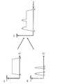
合成処理を模式的に表したのが図10(A)〜図10(C)である。図10(A)はカットフィルタ(バリアフィルタ)504の特性を示しており、白色光源503から照射されカットフィルタ504を透過した光の光強度は図10(A)の相似形となる。また、図10(B)はフィルタ508の特性を示しており、白色光源501から照射されフィルタ508を透過した光の光強度は図10(B)の相似形となる。
ここで前記相似形となるのは、白色光源501から放射される光強度は波長によらず一定という理想光源を仮定した場合に成り立つものである。以降、発明をより明確化する為に光源は前記理想光源として記述する。現実の光源の分光放射特性は均一ではなく、フィルタ508を通過した光強度は前記フィルタ504の特性と光源の分光放射特性のかけ算となるので厳密には相似形とはならない。FIGS. 10A to 10C schematically show the synthesis process. FIG. 10A shows the characteristics of the cut filter (barrier filter) 504, and the light intensity of the light emitted from the
Here, the similar shape is established when an ideal light source is assumed in which the light intensity emitted from the
図10(A)の白色光と、図10(B)の特定の波長帯域を有する光とを、図2のハーフミラー510の位置で合成することにより、図10(C)に示すような、特定の波長帯域が増強された白色光を取得することができる。取得した特定の波長帯域が増強された白色光を照射することで、全体の照射エネルギーを小さく抑えながら、明るくノイズの少ない特殊光画像を取得することが可能になる。詳細については第1の実施形態において説明する。 By combining the white light of FIG. 10A and the light having a specific wavelength band of FIG. 10B at the position of the
なお特定の波長帯域が増強された白色光を取得する方法は上記に限られず、光源部等は他の構成を取ることも可能である。変形例を第2の実施形態及び第3の実施形態において詳細に説明する。 Note that the method of acquiring white light with an enhanced specific wavelength band is not limited to the above, and the light source unit and the like can have other configurations. Modifications will be described in detail in the second embodiment and the third embodiment.
図1に、以上の本実施形態の手法を実現する光走査型光学装置の構成例を示す。この光走査型光学装置は、光制御部100、挿入部200、画像処理部300、表示部400、外部I/F部500を含む。光制御部100が本実施形態の光制御装置に対応し、光制御部100及び画像処理部300により本実施形態の制御装置が構成される。 FIG. 1 shows a configuration example of an optical scanning optical device that realizes the method of the present embodiment. The optical scanning optical device includes a
光制御部100は、光源部101、ハーフミラー102、光検出部103、テーパーロッド107、光コネクタ108、制御部109を含む。なお光制御部100の構成はこれに限定されず、これらの構成要素の一部を省略するなどの種々の変形実施が可能である。 The
挿入部200は例えば体腔への挿入を可能にするため細長くかつ湾曲可能に形成されている。挿入部200は、光ファイバー201と、光ファイバー201の光射出端部203を振動させるためのアクチュエータ202と、湾曲可能な先端部を自由にユーザーが操作制御するための操作部204により構成されている。アクチュエータ202としては、圧電素子、磁歪素子、或いは電磁誘導等を用いることが考えられる。 The
画像処理部300は、分類部301、スキャン変換部302、通常光画像生成部303、特殊光画像生成部304、出力画像生成部305を含む。なお画像処理部300の構成はこれに限定されず、これらの構成要素の一部を省略するなどの種々の変形実施が可能である。 The
表示部400はCRTや液晶モニタ等の動画表示可能な表示装置である。 The
外部I/F部500は、この光走査型光学装置に対するユーザーからの入力等を行うためのインターフェースであり、電源のオン/オフを行うための電源スイッチ、撮影モードやその他各種のモードを切り換えるためのモード切換ボタンなどを含んで構成されている。そして、この外部I/F部500は、入力された情報を、制御部109へ出力する。 The external I /
以下に光制御部100(光制御装置)の詳細を説明する。 Details of the light control unit 100 (light control device) will be described below.
光制御部100を構成する光源部101(光量増加部、光照射部を含む)からは特定波長光が増強された白色照明光(以下適宜、特定波長帯域増強白色光と呼ぶ)が射出される。光源部101からの特定波長帯域増強白色光はハーフミラー102を経由してテーパーロッド107の太端部に入射される。テーパーロッド107の細端部には光コネクタ108が設けられており、光ファイバー201の照明光の入力端にテーパーロッド107からの射出光である特定波長帯域増強白色光を送り込むようになっている。特定波長帯域増強白色光は光ファイバーの光射出端部203から被検体10に微小なスポット光として照射され、被検体10からの戻り光が再び光射出端部203に戻ってくる。 White illumination light with enhanced specific wavelength light (hereinafter, referred to as specific wavelength band enhanced white light as appropriate) is emitted from the light source unit 101 (including the light amount increasing unit and the light irradiating unit) constituting the
被検体10からの戻り光は光射出端部203から光ファイバー201に取り込まれ、光コネクタ108を経由してテーパーロッド107に戻り、ハーフミラー102で反射されて光検出部103に入射される。 Return light from the subject 10 is taken into the
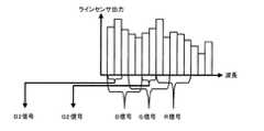
光検出部103に入射した光は、プリズム、或いは回折格子からなる分光器104にて分光され、この分光光(スペクトル光)が分光(拡散)する方向に沿って列状に配列されている光センサー105に照射される。光センサー105は光電変換可能なフォトダイオードやフォトトランジスタから構成されるラインセンサや、複数のフォトマル等を配置して構成したものであり、分光光の所定波長帯域単位(例えば10nm単位)に1つの光電変換素子が対応するような位置関係で配置されている。戻り光の分光光は光センサー105にて所定波長間隔でサンプリングして電気信号に変換された後、アナログ分光データとしてA/D変換部106に出力される。 The light incident on the
A/D変換部106は、サンプリングされたアナログ分光データを所定ビット数(例えば16ビット)で量子化し、デジタルデータに変換する。A/D変換部106からのデジタル分光データは画像処理部300へ出力される。 The A /
続いて第1実施形態の光源部101の詳細を図2に基づいて説明する。 Next, details of the
光源部101は、白色光源501、503と、カットフィルタ502、504と、フィルタ506〜508と、全反射ミラー509と、ハーフミラー510と、集光レンズ511から構成される。白色光源501、503はハロゲンやキセノンランプ、白色LED等により実現される。カットフィルタ502、504は白色光源の紫外域と赤外域をカットするUV・IRカットフィルタである。フィルタ506〜508はそれぞれ異なる分光透過率特性をもつフィルタであり、自動或いは手動で移動可能なフォルダ505に収められている。 The
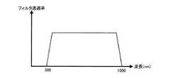
白色光源501、503から射出された平行光(略平行光を含む)は、図3或いは図4のフィルタ透過率を持つカットフィルタ502、504で不要な波長帯域をカットした白色光となる。ここで図3と図4の違いは近赤外域の波長をカットするかどうかであり、赤外域の蛍光を観察するモードを持つ光走査型光学装置(画像処理装置)においては図4の特性を、赤外域の蛍光を観察するモードを持たない場合は図3の特性を有する。或いは、このフィルタ502、504を不図示のターレットに収め、上記観察モードの選択により切り替えられる構成としても良い。カットフィルタの詳細については後述する。 Parallel light (including substantially parallel light) emitted from the
フォルダ505は、制御部109からの観察モードの指定により、自動的に白色光の光路に対応するフィルタ(506、507、508)が位置するように移動可能な構成となっている。 The
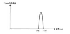
以下に3つの観察モード(NBIモード、蛍光観察モード、IRIモード)と一対一で対応するフィルタ(508、507、506)の関係を示す。ここでフィルタ508は図5の分光透過率特性を、フィルタ507は図6の分光透過率特性を、フィルタ506は図7の分光透過率特性を持つものとする。 The relationship between the three observation modes (NBI mode, fluorescence observation mode, IRI mode) and the filters (508, 507, 506) that correspond one-to-one is shown below. Here, it is assumed that the
図5の分光透過率特性は、B2が390〜445nm、G2が530〜550nmの範囲で透過し、それ以外は阻止域となる特性であり、特許文献1に記載されている2つの透過光の反射光画像から血管と粘膜表層の微細構造を観察するNBIモード時のものである。図6の分光透過率特性は、R2が600〜650nmで透過し、それ以外は阻止域となる特性であり、例えば透過光を励起光として赤外域の薬剤蛍光の蛍光画像観察モード時のものである。図7の分光透過率特性は、IR2が790〜820nm、IR3が905〜970nmの近赤外域の範囲で透過し、それ以外は阻止域となる特性であり、これら2つの近赤外域の透過光の反射光画像を観察するIRIモード時のものである。 The spectral transmittance characteristics of FIG. 5 are characteristics in which B2 is transmitted in the range of 390 to 445 nm and G2 is in the range of 530 to 550 nm, and the other is a blocking region. This is in the NBI mode in which the fine structure of the blood vessel and the mucous membrane surface layer is observed from the reflected light image. The spectral transmittance characteristics in FIG. 6 are characteristics in which R2 is transmitted at 600 to 650 nm, and other than that is a blocking area. For example, in the fluorescence image observation mode of drug fluorescence in the infrared region using transmitted light as excitation light. is there. The spectral transmittance characteristic of FIG. 7 is a characteristic that transmits in the near infrared region where IR2 is 790 to 820 nm and IR3 is 905 to 970 nm, and other than that is a blocking region. Transmitted light in these two near infrared regions In the IRI mode for observing the reflected light image.
NBIモードにおいては、白色光源501から射出され、フィルタ502(図3の特性)により不要な波長帯域をカットした白色光は、フォルダ505内のフィルタ508を通る。フィルタ508は図5の透過率特性を持つので、フィルタ508を透過した光として、図8(B)に示すように、B2が390〜445nm、G2が530〜550nmのみの波長からなる特殊光が得られる。この特殊光は全反射ミラー509で反射され、ハーフミラー510へ入射される。一方、白色光源503とフィルタ504(図3の特性)により不要な波長帯域をカットした白色光(図8(A)の特性)がハーフミラー510に入射される。ハーフミラー510に入射される2つの入射光は特殊光波長帯域が増強された白色光となり、集光レンズ511に入射される。この特殊光波長帯域増強白色光は集光レンズ511により光線が絞られ、ハーフミラー102を経由してテーパーロッド107の太端面に入射される。以上のように光源部101からは、結果として図8(C)に示すように、特定の波長帯域(NBIモードにおいてはB2、G2)が増強された白色光が照射されることになる。 In the NBI mode, white light emitted from the
蛍光観察モードにおいては、フィルタ502、504は図4の特性を有する。よってフィルタ507を透過した光は図9(B)に示すように、600〜650nm(R2)のみの波長からなる特殊光が得られ、ハーフミラー510へ入射される。一方、フィルタ504を透過した光は図9(A)に示すような波長帯域を持ち、同様にハーフミラー510に入射される。結果として光源部101から出力される白色光の分光放射特性は図9(C)に示すような特性を有する。 In the fluorescence observation mode, the
IRIモードにおいては、フィルタ502、504は図3の特性を有する。よってフィルタ506を透過した光は図10(B)に示すように、IR2が790〜820nm、IR3が905〜970nmのみの波長からなる特殊光が得られ、ハーフミラー510へ入射される。一方、フィルタ504を透過した光は図10(A)に示すような波長帯域を持ち、同様にハーフミラー510に入射される。結果として光源部101から出力される白色光の分光放射特性は図10(C)に示すような特性を有する。 In the IRI mode, the
以上に示したように、蛍光観察モード用のフィルタ507を用いる場合と、IRIモード用のフィルタ506を用いる場合では、カットフィルタ502、504の特性を切り替える必要がある。以下その理由について図を用いて説明する。 As described above, it is necessary to switch the characteristics of the cut filters 502 and 504 when using the
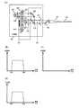
図11(A)〜図11(E)は、蛍光観察モード用フィルタ507の使用時に、図3の特性のカットフィルタ502、504を用いた場合に生じる不具合について説明する図である。 FIG. 11A to FIG. 11E are diagrams for explaining problems that occur when the cut filters 502 and 504 having the characteristics shown in FIG. 3 are used when the fluorescence
図11(A)において、(B)の位置の光はカットフィルタ502、504を通過した光であるため、図11(B)の特性を有する。また(C)の位置の光は(B)の光が蛍光観察モード用フィルタ507を通過した光であるため、図11(C)の特性を有する。(B)の光と(C)の光が合成された(D)の位置の光は図11(D)の特性を有する。図11(D)の光を被検体に照射した場合、600〜650nmの励起光の照射により、650nm〜の波長帯域を有する蛍光が発生する。しかし蛍光の光強度は照射光の反射光に比べて非常に弱いため、図11(E)に示すように、反射光に埋もれて蛍光の観察は困難である。よって本実施形態の蛍光観察を行うためには、照射光の反射光と、蛍光の波長帯域が重複しないように設定する必要があることがわかる。つまりカットフィルタ502、504は図3の特性ではなく、図4の特性のものを用い、照射光として図9(C)に示すような特定波長帯域増強白色光を採用する必要がある。 In FIG. 11A, the light at the position (B) is light that has passed through the cut filters 502 and 504, and thus has the characteristics shown in FIG. The light at the position (C) has the characteristics shown in FIG. 11C because the light at (B) has passed through the fluorescence
また、図12(A)〜図12(D)はIRIモード用フィルタ506の使用時に、図4の特性のカットフィルタ502、504を用いた場合に生じる不具合について説明する図である。 FIGS. 12A to 12D are diagrams for explaining problems that occur when the cut filters 502 and 504 having the characteristics shown in FIG. 4 are used when the
図12(A)において、(B)の位置の光はカットフィルタ502、504を通過した光であるため、図12(B)の特性を有する。また(C)の位置の光は(B)の光がIRIモード用フィルタ506を通過した光であるため、図12(C)の特性を有する。(B)の光と(C)の光が合成された(D)の位置の光は図12(D)の特性を有する。図から明らかなように、フィルタ506を通過させることで380〜650nmの光は全て遮断されてしまう。そのため(D)の位置においても特定波長帯域増強白色光を取得することができない。つまりカットフィルタ502、504は図4の特性ではなく、図3の特性のものを用いる必要がある。 In FIG. 12A, the light at the position (B) is light that has passed through the cut filters 502 and 504, and thus has the characteristics shown in FIG. The light at the position (C) has the characteristics shown in FIG. 12C because the light (B) has passed through the
以上の理由により、カットフィルタ502、504の特性は使用するモードにあわせて適切に選択されなくてはならない。なおNBIモードにおいては、蛍光観察モードやIRIモードのような制約はなく、カットフィルタ502、504は図3及び図4のどちらの特性を有していてもよい。 For the above reasons, the characteristics of the cut filters 502 and 504 must be appropriately selected according to the mode to be used. In the NBI mode, there is no restriction like the fluorescence observation mode and the IRI mode, and the cut filters 502 and 504 may have any of the characteristics shown in FIGS.
続いて挿入部200について詳細に説明する。 Next, the
挿入部200は光コネクタ108と接続されており、テーパーロッド107を通して光ファイバー201に光源部101から射出された特定波長帯域増強白色光が入射される。挿入部200のアクチュエータ202は光ファイバー201を同心円状に覆うように設置されており、光ファイバー201が通る軸に対して直交する2軸方向に所定周波数で振動する事で、アクチュエータ202に覆われていない光ファイバー201の光射出端部203までの間の部分を共振させる。その振動制御は制御部109からの制御信号で行なう。特に制御部109はアクチュエータ202に2軸方向に対する振動振幅を可変制御する事で光射出端部203を例えば図20のようならせん状の軌跡を周期的に繰り返し描くように制御する。アクチュエータ202に対する上記制御情報と光射出端部203の軌跡位置の対応関係を表す軌跡位置情報は予めテーブル化、或いは関数化されており、制御部109に格納されている。 The
このような軌跡を描きながら光射出端部203からは特定波長帯域増強白色光が被検体10に対して小さなスポット光として照射される。このスポット光からの戻り光が撮像画像の画素情報に相当する。スポット光の戻り光は光射出端部203から光ファイバー201に戻りテーパーロッド107を経由してハーフミラー102にて戻り光が反射されて光検出部103に入射される。 The specific wavelength band-enhanced white light is emitted as a small spot light to the subject 10 from the
続いて画像処理部300について詳細を説明する。 Next, details of the
光検出部103に入射した戻り光が光検出部103からデジタル分光データとして分類部301に出力される。分類部301には、光検出部103からデジタル分光データが入力され、制御部109から観察モードに対応する各色信号の分光データ重み係数が入力される。分類部301(色信号生成部)は、各波長に対するデジタル分光データと各色信号に対する所定の重みを乗算した後、重み付き分光データを積和演算する事により色信号を算出する。算出された色信号はスキャン変換部302へ出力される。 The return light incident on the
例えばNBIモードであれば、分類部301はR信号、G信号、B信号、G2信号(NBI−G信号)、B2信号(NBI−B信号)を生成する。 For example, in the NBI mode, the
スキャン変換部302には、分類部301からの色信号と、制御部109から光ファイバー201の光射出端部203の軌跡位置情報とが入力される。入力された色信号はメモリに格納される。一画面分の軌跡に対応する色信号(ここではまだらせん状)と、対応する軌跡位置情報に基づいて、通常の表示装置のラスタスキャン形式となるように一画面分の画像に変換する。単純な画素データの並び替えではラスタスキャン形式での所定サンプリング位置にサンプリングされていない場合があるので、その場合はその周辺画素を用いて補間処理を行い、画素を生成する。スキャン変換部302では入力される複数の色信号(例えばR信号、G信号、B信号、G2信号、B2信号)に対してそれぞれ一画面分の画像を生成する。生成した一画面分の画像のうち、通常光画像に対応する色信号(R信号、G信号、B信号)は通常光画像生成部303に、特殊光画像に対応する色信号(例えばG2信号、B2信号)は特殊光画像生成部304に出力される。 The
通常光画像生成部303及び特殊光画像生成部304は、それぞれ対応するノイズ低減処理、色補正処理、階調変換処理、強調処理等の画像処理を施し、通常光画像及び特殊光画像を出力画像生成部305に出力する。 The normal light
出力画像生成部305は、入力される特殊光画像から例えば扁平上皮癌等の病変部である褐色の領域を検出する。具体的には所定色相の領域が所定面積以上あると判定された場合は、通常光画像のその同一領域に特殊光画像をオーバーラップした出力画像を生成する。生成した出力画像は表示部400に出力される。 The output
表示部400(表示装置)は、出力画像生成部305から入力された出力画像を表示する。 The display unit 400 (display device) displays the output image input from the output
続いて分類部301、スキャン変換部302、出力画像生成部305の詳細を図13と図14に基づき説明する。 Next, details of the
図13に示すように、分類部301は、分光データ格納メモリ401、分類ユニット402〜406、分光分類係数設定部421を含む。なお分類部301の構成はこれに限定されず、これらの構成要素の一部を省略するなどの種々の変形実施が可能である。 As illustrated in FIG. 13, the
分類部301には光検出部103からデジタル分光データが入力され、分光データ格納メモリ401に一時的に格納される。分光データ格納メモリ401に格納されるデジタル分光データは、例えば400nm〜1000nmの範囲で10nm刻みの60個のデータとする。この60個のデジタル分光データは分類ユニット402〜406に出力される。 Digital spectral data is input to the
分光分類係数設定部421には、制御部109から選択した観察モードに対応する各色信号(NBIモードの場合はR,G,B,B2,G2)のそれぞれに対して60個の分光データ重み係数が入力され、各色信号に対応する分類ユニット402〜406にそれぞれ対応する重み係数がセットされる。 The spectral classification
図14は分類ユニット402〜406の詳細な構成例である。分類ユニット402〜406には、分光分類係数設定部421からの重み係数が入力され、入力された重み係数は、図14の重み係数格納メモリ702に格納される。分光データ格納メモリ401に格納されているデジタル分光データと、重み係数格納メモリ702に格納されている重み係数が、乗算器703_1〜703_N(ここでNは60)において乗算され、重み付分光データが積算器704にて積算されることで、色信号が生成される。FIG. 14 is a detailed configuration example of the
ここでデジタル分光データに対する重み係数について説明する。 Here, the weighting coefficient for the digital spectral data will be described.
NBIモードでは、分類ユニット402〜406に入力されるデジタル分光データは、図8(C)に示すように特定の波長帯域に対応する部分が増強された状態となっている。ここで分類ユニット402は通常光のR信号を、分類ユニット403は通常光のG信号を、分類ユニット404は通常光のB信号を生成する。分類ユニット405は特殊光のB2信号を、分類ユニット406は特殊光のG2信号を生成する。なお蛍光観察モードであれば信号はR信号、G信号、B信号、R2信号の4つであるため、分類ユニットも4つ使うだけで良いことは言うまでもない。 In the NBI mode, the digital spectroscopic data input to the
通常光用のR信号、G信号、B信号の3原色信号については特殊光のために増強された波長域(B2とG2に対応)を、それ以外の波長域と同等の重みになるように修正する必要がある。つまり、G信号とB信号を生成する分類ユニット403、404における重み係数は、図15に示すように増強されている波長域の重み係数が小さくなるように設定する必要がある。同様に蛍光観察モードでは図16に示すように、R2に対応する波長帯域の重み係数を小さく設定する必要がある。なおIRIモードにおいては、増強した波長帯域(IR2、IR3)とR信号、G信号、B信号の波長帯域とは重複しないため、通常光用の信号を作るに当たって重み係数を小さく設定する必要はない。 For the three primary color signals of R signal, G signal, and B signal for normal light, the wavelength range enhanced for special light (corresponding to B2 and G2) is set to have the same weight as other wavelength ranges. It needs to be corrected. In other words, the weighting factors in the
以下、特に断りがない場合はNBIモードを例にとって説明する。蛍光観察モード、IRIモードにおいても同様に処理されることは当業者には容易に理解可能であろう。 Hereinafter, the NBI mode will be described as an example unless otherwise specified. Those skilled in the art can easily understand that the same processing is performed in the fluorescence observation mode and the IRI mode.
特殊光用の重み係数は図5のフィルタ透過率のB2とG2の相似形となり、B2信号とG2信号を生成する分類ユニット405、406にセットされる。 The weighting factor for special light is similar to the filter transmittances B2 and G2 in FIG. 5, and is set in the
当然、重み係数は図15や図5に示しているように不必要な波長域については0を指定できるので、デジタル分光データを部分的に使用/不使用として選択できるようになっているのは言うまでも無い。 Naturally, as shown in FIG. 15 and FIG. 5, the weighting coefficient can be designated as 0 for an unnecessary wavelength region, so that digital spectral data can be partially selected as used / not used. Needless to say.
図17に観察モードがNBIモード時の5つの信号を生成するのに使用するデジタル分光データのグループ分類を模式的に示す。この図ではデジタル分光データの数は15個で40nm毎に分割したものであり、各色信号で使用するデジタル分光データの範囲を括弧で示している。同様に図18、図19は、各々、蛍光観察モード、IRIモードでのグループ分類を模式的に示す図である。 FIG. 17 schematically shows group classification of digital spectral data used to generate five signals when the observation mode is the NBI mode. In this figure, the number of digital spectral data is 15, which is divided every 40 nm, and the range of digital spectral data used for each color signal is shown in parentheses. Similarly, FIGS. 18 and 19 are diagrams schematically showing group classification in the fluorescence observation mode and the IRI mode, respectively.
スキャン変換部302は、通常光用色信号値格納メモリ407、特殊光用色信号値格納メモリ408、サンプリング位置情報格納メモリ409、補間処理部410〜411から構成される。 The
サンプリング位置情報格納メモリ409には制御部109から光ファイバー201の光射出端部203の軌跡位置情報がスキャン順に入力され、格納される。軌跡位置情報は2次元座標となる。 In the sampling position
通常光用色信号値格納メモリ407には分類ユニット402、403、404からのR、G、B信号が入力されスキャン順に格納される。 The normal light color signal
特殊光用色信号値格納メモリ408には分類ユニット405、406からのG2、B2信号が入力されスキャン順に格納される。 The special light color signal
補間処理部410には通常光用色信号値格納メモリ407からのR、G、B信号とサンプリング位置情報格納メモリ409からの軌跡位置情報が入力される。対応する軌跡位置情報に基づき、入力されたR、G、B信号を補間処理部410が有するラスタスキャン用メモリに格納する。この際、R,G,B信号は図20に示すように、2次元らせん状になっているため、各画素は本来の位置からずれる。この場合の2次元らせんスキャンをラスタスキャンに変換する一例を以下に示す。 The
まずラスタスキャンのサンプリング位置の画素値をR(x,y)と2次元らせんスキャンのサンプリング位置の画素値をS(u,v)とする。ここでx及びuは水平方向の座標、y及びvは垂直方向の座標であり、2つの座標間のスケールは表示倍率に合わせた状態とする。そしてラスタスキャンのサンプリング位置(x,y)を囲み、且つ距離が近い3つの2次元らせんスキャンのサンプリング位置(u1,v1)、(u2,v2)、(u3,v3)を検索する。前記3つのサンプリング位置(u1,v1)、(u2,v2)、(u3,v3)と前記(x,y)との距離D1,D2,D3を算出し、以下の式(1)に基づきR(x,y)を算出する。First, let R (x, y) be the pixel value at the sampling position of the raster scan and S (u, v) be the pixel value at the sampling position of the two-dimensional spiral scan. Here, x and u are horizontal coordinates, y and v are vertical coordinates, and the scale between the two coordinates is in a state matched to the display magnification. Then, the sampling positions (u1, v1), (u2 , v2), (u3, v3) of three two-dimensional helical scans that surround the raster scanning sampling position (x, y) and are close to each other are searched. The distances D1, D2, D3 between the three sampling positions (u1, v1), (u2 , v2), (u3, v3) and (x, y) are calculated, and R is calculated based on the following equation (1). Calculate (x, y).
R(x,y)=S(u1,v1)α+S(u2,v2)β+S(u3,v3)γ
α=(D2+D3)/{2(D1+D2+D3)}
β=(D1+D3)/{2(D1+D2+D3)}
γ=(D1+D2)/{2(D1+D2+D3)} ・・・・・(1)R (x, y) = S (u1, v1) α + S (u2, v2) β + S (u3, v3) γ
α = (D2 + D3) / {2 (D1 + D2 + D3)}
β = (D1 + D3) / {2 (D1 + D2 + D3)}
γ = (D1 + D2) / {2 (D1 + D2 + D3)} (1)
上記処理の後にラスタスキャンのサンプリング位置に欠落がある場合には、その周辺の隣接画素で線形補間、或はメディアン値(メディアンフィルタ)を使ってその欠落画素の画素値を決定する。 When there is a missing raster scan sampling position after the above processing, the pixel value of the missing pixel is determined using linear interpolation or a median value (median filter) in neighboring neighboring pixels.
上記の補間処理により、図21に示すような2次元ラスタスキャン形式の画像に変換される。スキャン変換が終了した通常光画像は通常光画像生成部303へ出力される。 By the above-described interpolation processing, the image is converted into a two-dimensional raster scan format image as shown in FIG. The normal light image that has undergone the scan conversion is output to the normal light
補間処理部411には特殊光用色信号値格納メモリ407からのG2、B2信号とサンプリング位置情報格納メモリ409からの軌跡位置情報が入力される。対応する軌跡位置情報に基づき、入力されたG2、B2信号を補間処理部411が有するラスタスキャン用メモリに格納する。格納位置については通常光時と同様に上式(1)を用いてラスタスキャン形式に変換される。スキャン変換が終了した特殊光画像は特殊光画像生成部304へ出力される。特殊光画像生成部304では入力されるG2、B2信号の2チャンネルを擬似的に3チャンネル化した特殊光画像を生成し、病変検出部412と合成処理部413へ出力される。 The
出力画像生成部305は病変検出部412と合成処理部413から構成される。 The output
病変検出部412には特殊光画像生成部304にて生成された特殊光画像が入力され、所定色相の領域を抽出する。前記抽出領域で連結する領域をグルーピングしグルーピング後の面積が所定閾値以上か判定を行なう。面積が所定閾値以上と判定された場合には、グルーピング領域を囲む矩形、或いは円形領域を設定し、合成処理部413に出力される。 The
合成処理部413には、病変検出部412からの病変検出領域と、通常光画像生成部303からの通常光画像と、特殊光画像生成部304からの特殊光画像とが入力される。病変検出領域に基づき通常光画像の一部領域をカットし、その位置に対する特殊光画像から病変検出領域を抽出して通常光画像に貼り付け、得られた画像が表示部400に出力されて表示される。 The
以上の本実施形態は、スポット光を被検体に対して照射し、スポット光を走査しながら、その戻り光を検出する光走査型光学装置(狭義には例えば内視鏡装置)に搭載される光制御装置に適用できる。光制御装置とは本実施形態における光制御部100に対応し、光制御部100は、光量増加部と、光照射部と、光検出部103を含む。光量増加部と光照射部は例えば光源部101により実現され、光量増加部は白色光光源から特定波長帯域増強白色光を取得し、光照射部は光量増加部で取得した特定波長帯域増強白色光を照射する。また光検出部103は特定波長帯域増強白色光の照射による被検体からの戻り光を検出する。 The present embodiment described above is mounted on an optical scanning optical apparatus (for example, an endoscope apparatus in a narrow sense) that irradiates a subject with spot light and scans the spot light while detecting the return light. Applicable to light control devices. The light control device corresponds to the
ここで、スポット光とはスポット状に被検体に対して照射される光のことである。また、特定波長帯域増強白色光とは特定の波長帯域(狭義には蛍光を発生させるための励起光や、狭帯域光等の波長帯域)の光強度が、白色光の他の帯域の光強度に比べ大きくなっている白色光のことであり、具体的には図8(C)、図9(C)、図10(C)に示すような特性を有する。 Here, the spot light is light irradiated to the subject in a spot shape. The specific wavelength band-enhanced white light means that the light intensity of a specific wavelength band (in the narrow sense, excitation light for generating fluorescence, wavelength band of narrow band light, etc.) is the light intensity of other bands of white light. The white light is larger than that of FIG. 8, and specifically has the characteristics shown in FIGS. 8C, 9C, and 10C.
これにより、白色光を照明光としてスポット状に集中した場合でも全体のエネルギーを抑えつつ特殊光のみの波長帯域のエネルギーを大きくできるので、照射される生体に与えるダメージを抑えながら、通常光画像と特殊光画像の同時撮影が可能となる。よって特殊光の波長光をより明るい照明光とする事ができ、その反射光で得られる特殊光画像において低ノイズでクリアな画像を生成できる。 As a result, even when white light is concentrated in the spot shape as illumination light, the energy in the wavelength band of only special light can be increased while suppressing the overall energy. Special light images can be taken simultaneously. Therefore, the wavelength light of the special light can be made brighter illumination light, and a clear image with low noise can be generated in the special light image obtained from the reflected light.
また、光量増加部は特定の波長帯域の光量を増加させることで、特定波長帯域増強白色光を取得する。 In addition, the light amount increasing unit increases the light amount in the specific wavelength band to acquire the specific wavelength band enhanced white light.
これにより、白色光光源は波長帯域全体にわたって光強度が強いものを使わなくとも、特定波長帯域増強白色光を取得することができる。ここで光強度が強いとは、第3の実施形態で使用される白色光光源と比べた場合の強弱を表す。後述するように第3の実施形態では、特定の波長帯域以外の波長帯域の光をフィルタで遮断することで特定波長帯域増強白色光を取得する。そのため、本実施形態と同等の光強度を持つ特定波長帯域増強白色光を取得するためには元の白色光光源の光強度を、本実施形態に比べて強くする必要があり、その点で本実施形態は利点を有する。 As a result, it is possible to acquire specific wavelength band-enhanced white light without using a white light source having a high light intensity over the entire wavelength band. Here, the high light intensity represents the strength when compared with the white light source used in the third embodiment. As will be described later, in the third embodiment, specific wavelength band enhanced white light is obtained by blocking light in a wavelength band other than the specific wavelength band with a filter. Therefore, in order to acquire specific wavelength band enhanced white light having the same light intensity as that of the present embodiment, it is necessary to increase the light intensity of the original white light source as compared with the present embodiment. Embodiments have advantages.
また、光量増加部は白色光光源から第1の白色光と第2の白色光を取得する。そして第1の白色光から特定の波長帯域を有する光を取得し、取得した特定の波長帯域を有する光と第2の白色光を合成することで、特定波長帯域増強白色光を取得する。 Further, the light quantity increasing unit obtains the first white light and the second white light from the white light source. Then, light having a specific wavelength band is acquired from the first white light, and the specific wavelength band-enhanced white light is acquired by combining the acquired light having the specific wavelength band and the second white light.
これにより、白色光源から特定波長の光を取得するのに、任意の波長帯域フィルタを設計するだけで済むので低コストに特定波長帯域増強白色光を取得することが可能となる。 As a result, in order to acquire light of a specific wavelength from a white light source, it is only necessary to design an arbitrary wavelength band filter, so that it is possible to acquire specific wavelength band-enhanced white light at a low cost.
また、白色光光源として、第1の白色光光源と第2の白色光光源が設けられてもよい。そして光量増加部は、第1の白色光光源から第1の白色光を取得し、第2の白色光光源から第2の白色光を取得しても良い。一例としては図2の構成がある。 In addition, as the white light source, a first white light source and a second white light source may be provided. The light amount increasing unit may acquire the first white light from the first white light source and acquire the second white light from the second white light source. An example is the configuration of FIG.
これにより、第1の白色光と第2の白色光の合成という手法に際して、それぞれの光を取得するための白色光光源を別々に用意することで大光量の特定波長帯域増強白色光を取得することが可能となる。 Thereby, in the method of combining the first white light and the second white light, a white light source for acquiring the respective lights is separately prepared to acquire a large amount of specific wavelength band enhanced white light. It becomes possible.
また、光量増加部は、特定の波長帯域を透過するフィルタ(具体的には図2におけるフィルタ506、507、508等。特性については図5、図6、図7に示す)を用いることで、特定の波長帯域を有する光を取得する。 Further, the light quantity increasing unit uses a filter that transmits a specific wavelength band (specifically, filters 506, 507, 508, etc. in FIG. 2; the characteristics are shown in FIGS. 5, 6, and 7). Light having a specific wavelength band is acquired.
これにより、光源自体に特殊光を発生させるようなものを採用する必要がなくなり、光源としては白色光光源のみから特定波長帯域増強白色光を取得することが可能となる。そのためコストの削減にもつながる。 Thereby, it is not necessary to employ a light source that generates special light, and it is possible to acquire specific wavelength band-enhanced white light only from a white light source as the light source. This leads to cost reduction.
また、フィルタとして、第1〜第Nのフィルタ(例えば図2におけるフィルタ506、507、508等。特性については図5、図6、図7に示す)が設けられ、第1〜第Nのフィルタのうちの第iのフィルタを用いることで、第iの特定の波長帯域(例えば図8(B)に示すような390〜445nm、530〜550nmという波長帯域)を有する光を取得する。具体的には、NBIモード用・蛍光観察モード用・IRIモード用の3つのフィルタを用意して、必要に応じて切り替えることで、取得する特定の波長帯域を有する光も切り替える。 Further, as the filters, first to Nth filters (for example, filters 506, 507, and 508 in FIG. 2 and the like, whose characteristics are shown in FIGS. 5, 6, and 7) are provided, and the first to Nth filters are provided. By using the i-th filter, light having an i-th specific wavelength band (for example, wavelength bands of 390 to 445 nm and 530 to 550 nm as shown in FIG. 8B) is acquired. Specifically, three filters for NBI mode, fluorescence observation mode, and IRI mode are prepared, and the light having a specific wavelength band to be acquired is switched by switching as necessary.
これにより、フィルタを適宜切り替えることで、例えばNBIモード・蛍光観察モード・IRIモードの3つのように異なるモードを自由に選択することが可能になる。 Thereby, it is possible to freely select different modes such as NBI mode, fluorescence observation mode, and IRI mode by appropriately switching the filters.
また、光量増加部は白色光光源からの白色光に対して、赤外光及び紫外光を遮断するカットフィルタを適用する。ここでカットフィルタとして第1のカットフィルタと第2のカットフィルタが設けられ、第1のカットフィルタは第2のカットフィルタに比べて、長波長帯域側のカットオフ波長が大きい特性を有する。具体的には例えば、第1のカットフィルタは図3に示す特性を有し、第2のカットフィルタは図4に示す特性を有することが考えられる。さらに第1のカットフィルタと第2のカットフィルタのどちらが適用されるかは、前述した第1〜第Nのフィルタのうち、どのフィルタが用いられたかに応じて決定される。具体的には前述したように蛍光観察モード用のフィルタ507が用いられた場合には第2のカットフィルタが、IRIモード用のフィルタ506が用いられた場合には第1のカットフィルタが採用される。 The light quantity increasing unit applies a cut filter that blocks infrared light and ultraviolet light with respect to white light from the white light source. Here, a first cut filter and a second cut filter are provided as the cut filters, and the first cut filter has a characteristic that the cutoff wavelength on the long wavelength band side is larger than that of the second cut filter. Specifically, for example, it is conceivable that the first cut filter has the characteristics shown in FIG. 3, and the second cut filter has the characteristics shown in FIG. Further, which of the first cut filter and the second cut filter is applied is determined according to which of the first to Nth filters described above is used. Specifically, as described above, when the
ここで、蛍光観察モード用フィルタ507が用いられた場合に第1のカットフィルタ(図3の特性)を採用した時や、IRIモード用フィルタ506が用いられた場合に第2のカットフィルタ(図4の特性)を採用した時には不具合が生じる。具体的には図11(A)〜図11(E)及び図12(A)〜図12(D)を用いて前述した通りである。蛍光観察モードにおいては、図11(E)に示すように照射光の反射光と蛍光の波長帯域が重複してしまい、蛍光の観察が困難になる。IRIモードにおいては、図12(D)に示すように、そもそも特定波長帯域増強白色光を取得することができない。以上の理由から第1〜第Nのフィルタのうち、どのフィルタが用いられたかによって、適用するカットフィルタの特性も変化させる必要がある。 Here, when the first cut filter (characteristic of FIG. 3) is adopted when the fluorescence
適用するカットフィルタの特性を適切に選択することで、使用するモードに応じた波長帯域を有する白色光を取得することが可能になる。 By appropriately selecting the characteristics of the cut filter to be applied, white light having a wavelength band corresponding to the mode to be used can be acquired.
また、第2のカットフィルタは、使用するフィルタに対応する特定の波長帯域の光は透過させたうえで、特定の波長帯域を有する光を照射することで発生する蛍光に対応する波長帯域の光は遮断する特性を有する。具体的には例えば、蛍光観察モード用のフィルタを使用する場合において、特定の波長帯域に対応する600〜650nmの光は透過させるが、発生する蛍光に対応する650nm〜の光(650nmよりも長波長帯域の光)は遮断する。 The second cut filter transmits light having a specific wavelength band corresponding to the filter to be used, and then irradiates light having a specific wavelength band with light having a wavelength band corresponding to fluorescence generated. Has a blocking property. Specifically, for example, when a filter for a fluorescence observation mode is used, light of 600 to 650 nm corresponding to a specific wavelength band is transmitted, but light of 650 nm to corresponding to generated fluorescence (longer than 650 nm) is transmitted. Light in the wavelength band) is blocked.
これにより、照射光としての特定波長帯域増強白色光を適切に取得した上で、発生する蛍光に対応する波長帯域の光は照射しないことになる。つまり照射による反射光と、発生する蛍光の波長帯域が重複することを抑止することが可能になり、反射光により蛍光の観察が阻害されることを抑止することができる。なお蛍光は反射光に比べて、光量が非常に少ないため、反射光と波長帯域が重複してしまった場合には観察は困難である。 As a result, the specific wavelength band-enhanced white light as the irradiation light is appropriately acquired, and light in the wavelength band corresponding to the generated fluorescence is not irradiated. In other words, it is possible to prevent the reflected light due to irradiation and the wavelength band of the generated fluorescence from overlapping, and it is possible to suppress the observation of fluorescence from being inhibited by the reflected light. In addition, since the amount of light of fluorescence is much smaller than that of reflected light, observation is difficult when the reflected light and the wavelength band overlap.
また、特定の波長帯域とは、白色光の波長帯域よりも狭い帯域である。具体的には特定の波長帯域とは、血液中のヘモグロビンに吸収される波長の波長帯域である。さらに具体的には、390nm〜445nmまたは530nm〜550nmの波長帯域である。 The specific wavelength band is a band narrower than the wavelength band of white light. Specifically, the specific wavelength band is a wavelength band of a wavelength that is absorbed by hemoglobin in blood. More specifically, the wavelength band is 390 nm to 445 nm or 530 nm to 550 nm.
これにより、NBIと呼ばれる狭帯域光観察が可能になる。NBIでは生体の表層部及び、深部に位置する血管の構造を観察することができる。また得られた信号を特定のチャンネル(R,G,B)に入力することで、扁平上皮癌等の通常光では視認が難しい病変などを褐色等で表示することができ、病変部の見落としを抑止することができる。なお、390nm〜445nmまたは530nm〜550nmとはヘモグロビンに吸収されるという特性及び、それぞれ生体の表層部または深部まで到達するという特性から得られた波長帯域である。ただし、この場合の波長帯域はこれに限定されず、例えばヘモグロビンによる吸収と生体の表層部又は深部への到達に関する実験結果等の変動要因により、波長帯域の下限値が5%程度減少し、上限値が5%程度上昇することも考えられる。 Thereby, narrow-band light observation called NBI becomes possible. In NBI, it is possible to observe the structure of a blood vessel located in the surface layer part and deep part of a living body. In addition, by inputting the obtained signals to specific channels (R, G, B), lesions that are difficult to see with normal light such as squamous cell carcinoma can be displayed in brown, etc. Can be deterred. Note that 390 nm to 445 nm or 530 nm to 550 nm are wavelength bands obtained from the characteristic of being absorbed by hemoglobin and the characteristic of reaching the surface layer or deep part of the living body, respectively. However, the wavelength band in this case is not limited to this, and the lower limit of the wavelength band is reduced by about 5% due to factors such as absorption by hemoglobin and experimental results related to the arrival of the living body on the surface layer or the deep part. It is conceivable that the value increases by about 5%.
また、特定の波長帯域とは、蛍光物質に蛍光を発生させるための励起光の波長帯域であってもよい。 The specific wavelength band may be a wavelength band of excitation light for generating fluorescence in the fluorescent material.
これにより、蛍光観察が可能となる。励起光を照射することで、コラーゲンなどの蛍光物質からの自家蛍光や、蛍光薬剤を用いた薬剤蛍光を観察することができる。このような観察では病変を正常粘膜とは異なった色調で強調表示することができ、病変部の見落としを抑止すること等が可能になる。 Thereby, fluorescence observation becomes possible. By irradiating with excitation light, autofluorescence from a fluorescent substance such as collagen or drug fluorescence using a fluorescent drug can be observed. In such observation, the lesion can be highlighted with a color tone different from that of the normal mucous membrane, and the oversight of the lesion can be suppressed.
また、特定の波長帯域とは、赤外光の波長帯域であってもよい。具体的には790nm〜820nmまたは905nm〜970nmの波長帯域である。 Further, the specific wavelength band may be a wavelength band of infrared light. Specifically, the wavelength band is 790 nm to 820 nm or 905 nm to 970 nm.
これにより、IRIと呼ばれる赤外光観察が可能となる。赤外光が吸収されやすい赤外指標薬剤であるICG(インドシアニングリーン)を静脈注射した上で、上記波長帯域の赤外光を照射することで、人間の目では視認が難しい粘膜深部の血管や血流情報を強調表示することができ、胃癌の深達度診断や治療方針の判定などが可能になる。なお790nm〜820nmという波長帯域は赤外指標薬剤の吸収がもっとも強いという特性から、905nm〜970nmという波長帯域は赤外指標薬剤の吸収がもっとも弱いという特性から求められたものである。ただし、この場合の波長帯域はこれに限定されず、例えば赤外指標薬剤の吸収に関する実験結果等の変動要因により、波長帯域の下限値が5%程度減少し、上限値が5%程度上昇することも考えられる。 Thereby, infrared light observation called IRI becomes possible. Intravenous injection of ICG (Indocyanine Green), an infrared index drug that easily absorbs infrared light, and then irradiating with infrared light in the above wavelength band, it is difficult to visually recognize the blood vessels in the deep mucosa And blood flow information can be highlighted, making it possible to diagnose the depth of gastric cancer and determine the treatment policy. The wavelength band of 790 nm to 820 nm is obtained from the characteristic that the absorption of the infrared index drug is the strongest, and the wavelength band of 905 nm to 970 nm is determined from the characteristic that the absorption of the infrared index drug is the weakest. However, the wavelength band in this case is not limited to this. For example, the lower limit value of the wavelength band is decreased by about 5% and the upper limit value is increased by about 5% due to a variation factor such as an experimental result related to absorption of the infrared index drug. It is also possible.
また、本実施形態における光走査型光学装置は光走査型内視鏡であっても良い。 Further, the optical scanning optical device in the present embodiment may be an optical scanning endoscope.
これにより、本実施形態で示された光制御装置を搭載した光走査型内視鏡を実現することが可能になる。 This makes it possible to realize an optical scanning endoscope equipped with the light control device shown in the present embodiment.
また、本実施形態は前述してきた光制御装置である光制御部100と、画像処理部300とを含む制御装置にも適用できる。画像処理部300は白色光に対応する第1の画像と、特定の波長帯域に対応する第2の画像を生成し、第1の画像と第2の画像から出力画像を生成する。 The present embodiment can also be applied to a control device including the
これにより、まず光制御部において、光信号を取得し電気信号に変換した上でA/D変換をしてデジタル信号を取得することができる。そして画像処理部により、取得したデジタル信号に画像処理を施すことにより、適切な形式で画像を表示することが可能になる。具体的には、特定の波長帯域を増強したことにより白色光画像の色味が変化してしまうことを抑止したり、特定の領域(例えば内視鏡観察における病変部等)の色を変更することで、見落としを抑止する等の処理が考えられる。 Thereby, first, in the light control unit, an optical signal is acquired and converted into an electrical signal, and then A / D conversion is performed to acquire a digital signal. Then, by performing image processing on the acquired digital signal by the image processing unit, it is possible to display an image in an appropriate format. Specifically, the color of the white light image is prevented from changing due to enhancement of a specific wavelength band, or the color of a specific region (for example, a lesioned part in endoscopic observation) is changed. Thus, processing such as deterring oversight can be considered.
また、画像処理部300は分類部301と画像生成部306を含む。分類部301は戻り光に含まれる光信号を波長に応じて複数種類のグループに分類し、画像生成部306は分類部により分類されたグループに属する光信号に基づいて、被検体の画像を生成する。 The
これにより、戻り光から得た信号を、生成する画像の特性に合わせて、複数のグループに分類することが可能になる。 This makes it possible to classify the signals obtained from the return light into a plurality of groups according to the characteristics of the image to be generated.
また、分類部301は、白色光の波長帯域を有する光信号を含む第1のグループと、特定の波長帯域を有する特殊光の光信号を含む第2のグループとに分類する。 Further, the
これにより、白色光に対応する第1のグループと、特殊光に対応する第2のグループに分類することが可能になる。具体的には、NBIモードにおいてはR,G,B信号は第1のグループ(狭義には通常光グループ)に、B2,G2信号は第2のグループ(狭義には特殊光グループ)に分類され、適切に通常光画像と特殊光画像とを生成することができる。 Thereby, it becomes possible to classify | categorize into the 1st group corresponding to white light, and the 2nd group corresponding to special light. Specifically, in the NBI mode, the R, G, and B signals are classified into the first group (normal light group in the narrow sense), and the B2 and G2 signals are classified into the second group (special light group in the narrow sense). The normal light image and the special light image can be appropriately generated.
また、光検出部103は分光器104を用いて分光スペクトルを取得する。そして分類部301は取得した分光スペクトルに基づいて、第1のグループと第2のグループに分類する。 In addition, the
これにより、分光器という光学的にわかりやすい装置を用いてシステムを構成することが可能になる。分光器により、例えば10nm刻みに光信号を取得することができるため、光源として特殊なもの(例えば狭帯域光のB2信号に対応する光を照射する光源等)を用いる必要がなく、通常の白色光光源とハーフミラー、フィルタ等の組み合わせのみで、光源部を構成することが可能になる。また例えば10nm刻みの高精度で等間隔の信号を取得できるため、その後の分類部301による分類が容易になるという利点がある。 This makes it possible to configure the system using an optically understandable device called a spectroscope. Since a spectroscope can acquire an optical signal in increments of 10 nm, for example, it is not necessary to use a special light source (for example, a light source that emits light corresponding to the B2 signal of narrowband light), and ordinary white A light source unit can be configured only by a combination of a light source, a half mirror, a filter, and the like. Further, for example, since signals at equal intervals can be obtained with high accuracy in increments of 10 nm, there is an advantage that classification by the
また、画像生成部306は第1のグループに属する光信号に基づいて、第1の画像を生成し、第2のグループに属する光信号に基づいて、第2の画像を生成する。ここで第1の画像とは狭義には通常光画像のことであり、白色光の波長帯域における情報を含む画像である。また第2の画像とは狭義には特殊光画像のことであり、特殊光の波長帯域(具体的には例えば狭帯域光B2,G2の波長帯域)の情報を含む画像である。 The
これにより、分類部301の分類に基づいて、適切に通常光画像と特殊光画像を生成することが可能になる。 Accordingly, it is possible to appropriately generate the normal light image and the special light image based on the classification of the
また、第1のグループは白色光の波長帯域を構成する第1〜第Pの波長帯域を有する光信号を含む。そして画像生成部306は第1〜第Pの光信号に基づいて、第1の画像を構成する第1〜第Pの構成画像を生成する。ここで第1〜第Pの光信号とは具体的には、R色の光信号、G色の光信号及びB色の光信号であってもよい。また、ここでの構成画像とは、通常光画像を生成するために必要な各色の画像のことであり、具体的には画像領域全体にわたりR信号を有するR画像、全体にわたりG信号を有するG画像、全体にわたりB信号を有するB画像のことである。R画像をRチャンネルに、G画像をGチャンネルに、B画像をBチャンネルに入力することで通常光画像が得られることになる。 The first group includes optical signals having first to Pth wavelength bands constituting the wavelength band of white light. Then, the
これにより、白色光の波長帯域を構成する各光信号から、各色の構成画像を生成することが可能になる。具体的には例えばR色の光信号からR画像を取得し、同様にG画像及びB画像を取得することができる。これらの構成画像から通常光画像を生成する。なお白色光の波長帯域を構成する光信号としてR,G,Bの各光信号を例に挙げたが、光信号がこれに限定されないことは言うまでもない。 As a result, it is possible to generate a component image of each color from each optical signal constituting the wavelength band of white light. Specifically, for example, an R image can be acquired from an R color optical signal, and similarly, a G image and a B image can be acquired. A normal light image is generated from these constituent images. Note that although R, G, and B optical signals are taken as an example of the optical signal constituting the wavelength band of white light, it goes without saying that the optical signal is not limited to this.
また、第2のグループは特定の波長帯域を構成する第1〜第Q(Qは1以上の整数)の波長帯域(例えばNBIモードにおいては、B2に対応する390〜445nmの波長帯域が第1の波長帯域であり、G2に対応する530〜550nmの波長帯域が第2の波長帯域である)を有する光信号を含む。そして画像生成部は第1〜第Qの光信号に基づいて、第2の画像を構成する第1〜第Qの構成画像(例えばNBIモードにおいてはB2画像とG2画像)を生成する。 The second group is a first to Qth wavelength band (Q is an integer of 1 or more) constituting a specific wavelength band (for example, in the NBI mode, a wavelength band of 390 to 445 nm corresponding to B2 is the first wavelength band. And a wavelength band of 530 to 550 nm corresponding to G2 is a second wavelength band). Then, the image generation unit generates first to Qth component images (for example, a B2 image and a G2 image in the NBI mode) that constitute the second image based on the first to Qth optical signals.
これにより、特定の波長帯域を構成する各光信号から、各色の構成画像を生成することが可能になる。これらの構成画像から特殊光画像を生成する。具体的には例えば狭帯域光B2,G2の波長帯域を有する光信号に基づく構成画像であってもよいし、IRIモードのIR2、IR3の波長帯域を有する光信号に基づく構成画像であってもよい。また、光信号がこれらに限定されないことは言うまでもない。 Thereby, it is possible to generate a constituent image of each color from each optical signal constituting a specific wavelength band. A special light image is generated from these constituent images. Specifically, for example, a configuration image based on an optical signal having a wavelength band of narrowband light B2 or G2 may be used, or a configuration image based on an optical signal having a wavelength band of IR2 or IR3 in the IRI mode. Good. Needless to say, the optical signal is not limited to these.
また、光照射部はスポット光をらせん状に照射する。画像処理部300はスポット光の位置情報を取得するスキャン変換部302を含み、スキャン変換部302はさらに第1補間処理部410と第2補間処理部411を含む。第1補間処理部410は分類部301で分類された第1のグループに対応する第1の画像信号の配置態様を、位置情報に基づいてラスタスキャン形式に変換する。同様に第2補間処理部411は第2のグループに対応する第2の画像信号の配置態様を、ラスタスキャン形式に変換する。そして画像処理部300はラスタスキャン形式に変換された第1の画像信号に基づいて第1の画像を生成し、第2の画像信号に基づいて第2の画像を生成する。 Further, the light irradiation unit irradiates the spot light in a spiral shape. The
これにより、らせん状の走査により得られた画像(自然な画像ではなく、被検体が歪んで見える)を図21に示すようなラスタスキャン形式に変換することが可能になる。また前記スキャン形式を変換しただけでは、情報が格納されない画素が出てくるため、例えば線形補間やメディアンフィルタ等で補間値を算出する。そして得られたラスタスキャン形式の画像信号に基づいて画像を生成することができる。 This makes it possible to convert an image obtained by spiral scanning (not a natural image, but the subject appears distorted) into a raster scan format as shown in FIG. In addition, since only the scan format is converted, pixels in which information is not stored are generated. For example, an interpolation value is calculated by linear interpolation, a median filter, or the like. An image can be generated based on the obtained raster scan format image signal.
また、本実施形態は、本実施形態の光制御装置内の光照射部により照射された白色光を通過させ、被検体からの戻り光を光検出部に返す光学スコープにも適用できる。 The present embodiment can also be applied to an optical scope that passes white light irradiated by the light irradiation unit in the light control apparatus of the present embodiment and returns the return light from the subject to the light detection unit.
ここで光学スコープとは、図1における挿入部200に対応するもので、具体的には上部消化器用スコープや下部消化器用スコープ等がある。本実施形態のスコープでは、照明部と受光部を共通化できるので細径化が可能となる。 Here, the optical scope corresponds to the
また、本実施形態は、光量増加部と光照射部と光検出部とを含む光走査型光学装置にも適用できる。光量増加部と光照射部は光源部101により実現され、光量増加部は白色光光源から特定波長帯域増強白色光を取得し、光照射部は光量増加部で取得した特定波長帯域増強白色光を照射する。また光検出部103は特定波長帯域増強白色光の照射による被検体からの戻り光を検出する。 The present embodiment can also be applied to an optical scanning optical device including a light quantity increasing unit, a light irradiation unit, and a light detection unit. The light quantity increasing part and the light irradiating part are realized by the
これにより、白色光を照明光としてスポット状に集中した場合でも全体のエネルギーを抑えつつ特殊光のみの波長帯域のエネルギーを大きくできるので、照射される生体に与えるダメージを抑えながら、通常光画像と特殊光画像の同時撮影が可能となる。よって特殊光の波長光をより明るい照明光とする事ができ、その反射光で得られる特殊光画像において低ノイズでクリアな画像を生成できる光走査型光学装置(狭義には例えば光走査型内視鏡)を実現することが可能になる。 As a result, even when white light is concentrated in the spot shape as illumination light, the energy in the wavelength band of only special light can be increased while suppressing the overall energy. Special light images can be taken simultaneously. Therefore, the special wavelength light can be made brighter illumination light, and the optical scanning type optical device capable of generating a clear image with low noise in the special light image obtained by the reflected light (in the narrow sense, for example, in the optical scanning type). (Scope) can be realized.
また、光走査型光学装置は分類部を含んでも良い。 The optical scanning optical device may include a classification unit.
これにより、戻り光から得た信号を、生成する画像の特性に合わせて、複数のグループに分類することが可能になる。 This makes it possible to classify the signals obtained from the return light into a plurality of groups according to the characteristics of the image to be generated.
2.第2の実施形態
続いて第2実施形態について説明する。なお光源部101以外の構成は第1の実施形態と同様であるため、詳細な説明は省略する。光源部101の詳細を図22に示す。2. Second Embodiment Subsequently, a second embodiment will be described. Since the configuration other than the
光源部101は、第1実施形態に比べて高輝度が得られる白色光源601と、白色光源の紫外域と赤外域をカットするUV・IRカットフィルタ502と、複数の分光透過率特性を持つフィルタ(508、507)を収めた自動或いは手動で移動可能なフォルダ514と、全反射ミラー509、513と、ハーフミラー510、512と、集光レンズ511から構成される。 The
白色光源601から射出された平行光(略平行光を含む)は図4のフィルタ透過率を持つUV・IRカットフィルタ502で不要な波長帯域をカットした白色光となる。 The parallel light (including substantially parallel light) emitted from the
フォルダ514は制御部109からの観察モードにより、自動的に白色光の光路に対応するフィルタ(508、507)が位置するように移動可能な構成となっている。 The
白色光源601から射出されフィルタ502により不要な波長帯域をカットした白色光は、ハーフミラー512を透過してフォルダ514内のフィルタ507もしくは508に入射される。フィルタを透過させることで特定の波長帯域を有する光が取得される。取得された特定の波長帯域を有する光は全反射ミラー509で反射され、ハーフミラー510へ入射される。一方、ハーフミラー512を反射した白色光は全反射ミラー513で反射され、ハーフミラー510に入射される。ハーフミラー510に入射される2つの入射光が合成された光は特定波長帯域増強白色光となり、集光レンズ511に入射される。集光レンズ511により特定波長帯域増強白色光の光線が絞られ、ハーフミラー102を経由してテーパーロッド107の太端面に入射される。 White light emitted from the
特定波長帯域増強白色光が得られた後の処理は第1の実施形態と同様である。 The processing after the specific wavelength band enhanced white light is obtained is the same as that in the first embodiment.
なお第2の実施形態において、フィルタが508及び507(NBIモード、蛍光観察モード)の2種類のみとなっているのは、このような構成にすればカットフィルタ502の特性を切り替える必要がないからである。カットフィルタ502のフィルタ特性の切り替えも考慮するならば、第1の実施形態と同様に3種類(もしくはそれ以上)のフィルタを使用することができるのは言うまでもない。 In the second embodiment, there are only two types of filters, 508 and 507 (NBI mode and fluorescence observation mode), because it is not necessary to switch the characteristics of the
以上の本実施形態では、白色光光源として、単一の白色光光源601が設けられる。そして光量増加部は、単一の白色光光源601から第1の白色光と第2の白色光の両方を取得する。その際には例えばハーフミラーを用いることなどが考えられ、一例としては図22に示す構成がある。図22においては第1の白色光とは、ハーフミラー512を透過する(直進する)光であり、フィルタ(507、508)を透過することで特定の波長帯域を有する光となり、全反射ミラー509によって反射される。また、第2の白色光とは、ハーフミラー512で反射される光であり、全反射ミラー513によって反射される。 In the above embodiment, a single
これにより、白色光光源1つのみで光源部を構成することが可能となり、構成を簡単にすることができるとともに、コスト削減にもつながる。 This makes it possible to configure the light source unit with only one white light source, simplifying the configuration and reducing the cost.
3.第3の実施形態
続いて第3実施形態について説明する。なお光源部101以外の構成は第1の実施形態と同様であるため、詳細な説明は省略する。光源部101の詳細を図23に示す。3. Third Embodiment Subsequently, a third embodiment will be described. Since the configuration other than the
光源部101は、第1実施形態に対してより高輝度が得られる白色光源601と、白色光源の紫外域と赤外域をカットするUV・IRカットフィルタ502と、複数の分光透過率特性を持つフィルタ(602、603、604)を収めた自動或いは手動で移動可能なフォルダ505と、集光レンズ511から構成される。 The
白色光源601から射出された略平行光は図3のフィルタ透過率を持つUV・IRカットフィルタ502で不要な波長帯域をカットした白色光となる。 The substantially parallel light emitted from the
フォルダ505は制御部109からの観察モードにより、自動的に白色光の光路に対応するフィルタ(602、603、604)が位置するように移動可能な構成となっている。 The
白色光源601から射出されフィルタ502により不要な波長帯域をカットした白色光(図3の特性)はフォルダ505内のフィルタ602、603、604に入射される。フィルタ602は図24(図27(A))の特性を持つので、フィルタ602を透過した光は図27(B)に示すように、G2、B2の波長の光量が多く、それ以外の波長の光量が低減された白色光が得られる。同様にフィルタ603は図25(図28(A))の特性を持つので、フィルタ603を透過した光は図28(B)に示すように、R2の波長の光量が多く、それ以外の波長の光量が低減された白色光が得られる。フィルタ604は図26(図29(A))の透過率特性を持つのでフィルタ604を透過した光は図29(B)に示すように、IR2、IR3の波長の光量が多く、それ以外の波長の光量が低減された白色光が得られる。 White light (characteristics in FIG. 3) emitted from the
得られた白色光は集光レンズ511に入射される。集光レンズ511により白色光の光線が絞られ、ハーフミラー102を経由してテーパーロッド107の太端面に入射される。 The obtained white light is incident on the
特定波長帯域増強白色光が得られた後の処理は、第1の実施形態と同様である。 The processing after the specific wavelength band enhanced white light is obtained is the same as that in the first embodiment.
以上の本実施形態では、光量増加部は特定の波長帯域以外の波長帯域の光量を減少させることで、特定波長帯域増強白色光を取得する。 In the present embodiment described above, the light amount increasing unit acquires the specific wavelength band-enhanced white light by decreasing the light amount in the wavelength band other than the specific wavelength band.
これにより、2つ以上の光を合成するような処理を行う必要がなくなるため、光源部の構成を簡略化することが可能になり、コスト削減につながる。 As a result, it is not necessary to perform a process of combining two or more lights, so that the configuration of the light source unit can be simplified, leading to cost reduction.
また、光量増加部は、特定の波長帯域を透過するフィルタ(具体的には図23におけるフィルタ602、603、604等。特性については図24、図25、図26に示す)を用いることで、特定波長帯域増強白色光を取得する。 In addition, the light quantity increasing unit uses a filter that transmits a specific wavelength band (specifically, filters 602, 603, 604, etc. in FIG. 23; the characteristics are shown in FIGS. 24, 25, and 26). Acquire specific wavelength band enhanced white light.
これにより、光源自体に特殊光を発生させるようなものを採用する必要がなくなり、光源としては白色光光源のみから特定波長帯域増強白色光を取得することが可能となる。さらにフィルタを一つ適用するだけで特定波長帯域増強白色光を取得できるため、複数の光源やハーフミラー等が必要なくなり、コストの削減にもつながる。 Thereby, it is not necessary to employ a light source that generates special light, and it is possible to acquire specific wavelength band-enhanced white light only from a white light source as the light source. Furthermore, the specific wavelength band-enhanced white light can be acquired by applying only one filter, which eliminates the need for a plurality of light sources, half mirrors, and the like, leading to cost reduction.
また、フィルタとして、第1〜第Mのフィルタ(例えば図23における、フィルタ602〜604。特性は図24〜図26に示す)が設けられ、第1〜第Mのフィルタのうちの第jのフィルタを用いることで、第jの特定波長帯域増強白色光(例えばNBIモードならば、図27(B)に示す特性を有する光)を取得する。具体的には例えば、NBIモード用・蛍光観察モード用・IRIモード用の3つのフィルタを用意して、必要に応じて切り替えることで、取得する特定波長帯域増強白色光も切り替える。 Further, as the filters, first to Mth filters (for example, filters 602 to 604 in FIG. 23, the characteristics are shown in FIGS. 24 to 26) are provided, and the jth of the first to Mth filters is provided. By using the filter, the jth specific wavelength band enhanced white light (for example, light having the characteristics shown in FIG. 27B in the NBI mode) is acquired. Specifically, for example, three filters for NBI mode, fluorescence observation mode, and IRI mode are prepared and switched as necessary to switch the acquired specific wavelength band-enhanced white light.
これにより、フィルタを適宜切り替えることで、例えばNBIモード・蛍光観察モード・IRIモードの3つのように異なるモードを自由に選択することが可能になる。更に白色光源を1つで構成することができるので、コスト削減が可能となる。またカットフィルタ502の特性を切り替える必要がないという利点もある。 Thereby, it is possible to freely select different modes such as NBI mode, fluorescence observation mode, and IRI mode by appropriately switching the filters. Furthermore, since a single white light source can be configured, cost can be reduced. There is also an advantage that it is not necessary to switch the characteristics of the
以上、本発明を適用した3つの実施の形態1〜3およびその変形例について説明したが、本発明は、各実施の形態1〜3やその変形例そのままに限定されるものではなく、実施段階では、発明の要旨を逸脱しない範囲内で構成要素を変形して具体化することができる。また、上記した各実施の形態1〜3や変形例に開示されている複数の構成要素を適宜組み合わせることによって、種々の発明を形成することができる。例えば、各実施の形態1〜3や変形例に記載した全構成要素からいくつかの構成要素を削除してもよい。さらに、異なる実施の形態や変形例で説明した構成要素を適宜組み合わせてもよい。このように、発明の主旨を逸脱しない範囲内において種々の変形や応用が可能である。 The three embodiments 1 to 3 to which the present invention is applied and the modifications thereof have been described above, but the present invention is not limited to the embodiments 1 to 3 and the modifications as they are, The constituent elements can be modified and embodied without departing from the spirit of the invention. Moreover, various inventions can be formed by appropriately combining a plurality of constituent elements disclosed in the above-described first to third embodiments and modifications. For example, some constituent elements may be deleted from all the constituent elements described in the first to third embodiments and the modifications. Furthermore, you may combine suitably the component demonstrated in different embodiment and modification. Thus, various modifications and applications are possible without departing from the spirit of the invention.
また、明細書又は図面において、少なくとも一度、より広義または同義な異なる用語(例えば第1の画像、第2の画像等)と共に記載された用語(例えば通常光画像、特殊光画像等)は、明細書又は図面のいかなる箇所においても、その異なる用語に置き換えることができる。 In the specification or drawings, terms (for example, a normal light image, a special light image, etc.) described together with different terms having a broader meaning or the same meaning (for example, the first image, the second image, etc.) at least once The different terms can be used anywhere in the book or drawing.
10 被検体、100 光制御部、101 光源部、102 ハーフミラー、
103 光検出部、104 分光器、105 光センサー、106 A/D変換部、
107 テーパーロッド、108 光コネクタ、109 制御部、
200 挿入部、201 光ファイバー、202 アクチュエータ、
203 光射出端部、204 操作部、300 画像処理部、301 分類部、
302 スキャン変換部、303 通常光画像生成部、304 特殊光画像生成部、
305 出力画像生成部、400 表示部、401 分光データ格納メモリ、
402〜406 分類ユニット、407 通常光用色信号値格納メモリ、
408 特殊光用色信号値格納メモリ、409 サンプリング位置情報格納メモリ、
410 第1補間処理部、411 第2補間処理部、412 病変検出部、
413 合成処理部、421 分光分類係数設定部、500 外部I/F部、
501 白色光源、502 カットフィルタ、503 白色光源、
504 カットフィルタ、505 フォルダ、506 IRIモード用フィルタ、
507 蛍光観察モード用フィルタ、508 NBIモード用フィルタ、
509 全反射ミラー、510 ハーフミラー、511 集光レンズ、
512 ハーフミラー、513 全反射ミラー、514 フォルダ、601 白色光源、
602 NBIモード用フィルタ、603 蛍光観察モード用フィルタ、
604 IRIモード用フィルタ、702 重み係数格納メモリ、704 積算器、
702_1〜702_N 乗算器10 subject, 100 light control unit, 101 light source unit, 102 half mirror,
103 photodetection unit, 104 spectrometer, 105 optical sensor, 106 A / D conversion unit,
107 taper rod, 108 optical connector, 109 control unit,
200 insertion part, 201 optical fiber, 202 actuator,
203 light exit end, 204 operation unit, 300 image processing unit, 301 classification unit,
302 scan conversion unit, 303 normal light image generation unit, 304 special light image generation unit,
305 output image generation unit, 400 display unit, 401 spectral data storage memory,
402 to 406 Classification unit, 407 Normal light color signal value storage memory,
408 Special light color signal value storage memory, 409 Sampling position information storage memory,
410 first interpolation processing unit, 411 second interpolation processing unit, 412 lesion detection unit,
413 synthesis processing unit, 421 spectral classification coefficient setting unit, 500 external I / F unit,
501 white light source, 502 cut filter, 503 white light source,
504 cut filter, 505 folder, 506 IRI mode filter,
507 Fluorescence observation mode filter, 508 NBI mode filter,
509 total reflection mirror, 510 half mirror, 511 condenser lens,
512 half mirror, 513 total reflection mirror, 514 folder, 601 white light source,
602 NBI mode filter, 603 Fluorescence observation mode filter,
604 IRI mode filter, 702 weight coefficient storage memory, 704 accumulator,
702_1 to 702_N multiplier
Claims (11)
Translated fromJapanese前記光制御部によって検出された反射光に基づいて、白色光に対応する第1の画像と、特定の波長帯域に対応する第2の画像とを生成する画像処理部と、
を備え、
前記光制御部は、
白色光光源からの白色光の波長帯域のうち、前記第2の画像に対応する前記特定の波長帯域内の光量を増加させる光量増加部と、
前記特定の波長帯域の光量が増加された白色光である特定波長帯域増強白色光を、前記被検体に照射する光照射部と、
前記特定波長帯域増強白色光の照射による、前記被検体からの反射光を検出し、分光データを生成する光検出部と、
を含み、
前記画像処理部は、
光量が増加された前記特定の波長帯域に対応する前記分光データによって前記第2の画像を生成し、
光量が増加された前記特定の波長帯域に対応する前記分光データに対する重みを、前記特定の波長帯域以外の波長帯域に対応する前記分光データに対する重みよりも小さくして算出した、前記特定の波長帯域に対応する前記分光データと前記特定の波長帯域以外の波長帯域に対応する前記分光データとの重み付け分光データにより、前記第1の画像を生成することを特徴とする光走査型内視鏡装置。A light control unit that irradiates the subject with light from a light source in a spot shape and detects the reflected light while scanning the spot light that is the light irradiated in the spot shape;
An image processing unit that generates a first image corresponding to white light and a second image corresponding to a specific wavelength band based on the reflected light detected by the light control unit;
With
The light control unit
A light amount increasing unit that increases a light amount in the specific wavelength band corresponding to the second image out of a wavelength band of white light from a white light source;
A light irradiation unit that irradiates the subject with specific wavelength band-enhanced white light that is white light in which the amount of light in the specific wavelength band is increased; and
A light detection unit that detects reflected light from the subject by irradiation with the specific wavelength band-enhanced white light,and generates spectral data ;
Including
The image processing unit
Wherein generatingthe second image bythe spectral data corresponding to the specific wavelengthband light amount is increased,
Weights for the spectral data corresponding to the specific wavelengthband light amount is increased,it is calculated to be smaller than the weight for the spectral data corresponding to the wavelength band other than the specific wavelengthband, the particular wavelength An optical scanning endoscope apparatusthat generatesthe first image by weighted spectral data of the spectral data corresponding to a band and the spectral data corresponding to a wavelength band other than the specific wavelength band .
前記特定の波長帯域は、前記白色光の波長帯域よりも狭い帯域であることを特徴とする光走査型内視鏡装置。In claim 1,
The optical scanning endoscope apparatus, wherein the specific wavelength band is a band narrower than the wavelength band of the white light.
前記画像処理部は、
前記第1の画像と前記第2の画像から出力画像を生成することを特徴とする光走査型内視鏡装置。In claim 1,
The image processing unit
An optical scanning endoscope apparatus, wherein an output image is generated from the first image and the second image.
前記分光データを、前記分光データに対応する波長に応じて、複数の種類のグループに分類する分類部と、
を備え、
前記画像処理部は、
前記分類部により分類されたグループに属する分光データに基づいて、前記第1の画像と前記第2の画像とを生成することを特徴とする光走査型内視鏡装置。In claim 1,
Thespectroscopic data, in accordance with the wavelengthcorresponding to the spectral data, a classification unit for classifying a plurality of kinds of groups,
With
The image processing unit
An optical scanning endoscope apparatus that generates the first image and the second image based onspectral data belonging to a group classified by the classification unit.
前記分類部は、
少なくとも、前記白色光の波長帯域に対応する分光データを含む第1のグループと、前記特定の波長帯域に対応する分光データを含む第2のグループとに分類することを特徴とする光走査型内視鏡装置。In claim 4,
The classification unit includes:
The optical scanning type is classified into at least a first group includingspectral data corresponding to the wavelength bandof the white light and a second group includingspectral data corresponding to the specific wavelength band. Endoscopic device.
前記光検出部は、
分光器を用いて分光スペクトルを取得し、
前記分類部は、
取得した前記分光スペクトルに基づいて、前記第1のグループと、前記第2のグループとに分類することを特徴とする光走査型内視鏡装置。In claim 5,
The light detection unit is
Use a spectroscope to acquire a spectral spectrum,
The classification unit includes:
An optical scanning endoscope apparatus that is classified into the first group and the second group based on the acquired spectrum.
前記画像処理部は、
前記第1のグループに属する分光データに基づいて、前記白色光の波長帯域における情報を含む前記第1の画像を生成し、前記第2のグループに属する分光データに基づいて、前記特殊光の波長帯域における情報を含む前記第2の画像を生成することを特徴とする光走査型内視鏡装置。In claim 5,
The image processing unit
Based on thespectral data belonging to the first group, the first image including information in the wavelength band of the white light is generated, and based on thespectral data belonging to the second group, the wavelength of the special light An optical scanning endoscope apparatus that generates the second image including information in a band.
前記第1のグループは、前記白色光の波長帯域を構成する第1〜第P(Pは2以上の整数)の波長帯域に対応する分光データを含み、
前記画像処理部は、
前記第1〜第Pの波長帯域に対応する分光データに基づいて、前記第1の画像を構成する第1〜第Pの構成画像を生成することを特徴とする光走査型内視鏡装置。In claim 7,
The first group includesspectral data corresponding to wavelength bandsof first to Pth (P is an integer of 2 or more) constituting the wavelength band of the white light,
The image processing unit
An optical scanning endoscope apparatus that generates first to P-th constituent images constituting the first image based onspectral data corresponding to the first to P-th wavelength bands.
前記第1〜第Pの波長帯域に対応する分光データは、R色に対応する分光データ、G色に対応する分光データおよびB色に対応する分光データであることを特徴とする光走査型内視鏡装置。In claim 8,
Thespectral data corresponding to the wavelength band of the first to P isthe spectral data corresponding to the R color, the optical scanning, characterized in that thespectral data corresponding to thespectral data, and B colorscorresponding to the G color Endoscopic device.
前記第2のグループは、前記特定の波長帯域を構成する第1〜第Q(Qは1以上の整数)の波長帯域に対応する分光データを含み、
前記画像処理部は、
前記第1〜第Qの波長帯域に対応する分光データに基づいて、前記第2の画像を構成する第1〜第Qの構成画像を生成することを特徴とする光走査型内視鏡装置。In claim 7,
The second group includesspectral data corresponding to the first to Qth wavelength bands (Q is an integer of 1 or more) constituting the specific wavelength band,
The image processing unit
An optical scanning endoscope apparatus that generates first to Q-th constituent images constituting the second image based onspectral data corresponding to the first to Q-th wavelength bands.
前記光照射部は、
前記スポット光を前記被検体にらせん状に照射し、
前記画像処理部は、
前記スポット光の位置情報を取得するスキャン変換部を含み、
前記スキャン変換部は、
分類された前記第1のグループに対応する第1の画像信号の配置態様を、前記スポット光の位置情報に基づいて、ラスタスキャン形式に変換する第1補間処理部と、
分類された前記第2のグループに対応する第2の画像信号の配置態様を、前記スポット光の位置情報に基づいて、ラスタスキャン形式に変換する第2補間処理部と、
を含み、
前記画像処理部は、
ラスタスキャン形式に変換された前記第1の画像信号に基づいて前記第1の画像を生成し、ラスタスキャン形式に変換された前記第2の画像信号に基づいて前記第2の画像を生成することを特徴とする光走査型内視鏡装置。
In claim 5,
The light irradiator is
Irradiating the spot light in a spiral to the subject,
The image processing unit
A scan conversion unit for acquiring the position information of the spot light;
The scan converter is
A first interpolation processing unit that converts an arrangement mode of the first image signals corresponding to the classified first group into a raster scan format based on the position information of the spot light;
A second interpolation processing unit that converts an arrangement mode of the second image signals corresponding to the classified second group into a raster scan format based on the position information of the spot light;
Including
The image processing unit
Generating the first image based on the first image signal converted into the raster scan format, and generating the second image based on the second image signal converted into the raster scan format. An optical scanning endoscope apparatus characterized by the above.
Priority Applications (3)
| Application Number | Priority Date | Filing Date | Title |
|---|---|---|---|
| JP2009284472AJP5570798B2 (en) | 2009-12-15 | 2009-12-15 | Optical scanning endoscope device |
| PCT/JP2010/071962WO2011074448A1 (en) | 2009-12-15 | 2010-12-08 | Light control device, control device, optical scope and optical scanning device |
| US13/488,633US9335269B2 (en) | 2009-12-15 | 2012-06-05 | Optical control device, control device, optical scope, and scanning optical device |
Applications Claiming Priority (1)
| Application Number | Priority Date | Filing Date | Title |
|---|---|---|---|
| JP2009284472AJP5570798B2 (en) | 2009-12-15 | 2009-12-15 | Optical scanning endoscope device |
Publications (3)
| Publication Number | Publication Date |
|---|---|
| JP2011127933A JP2011127933A (en) | 2011-06-30 |
| JP2011127933A5 JP2011127933A5 (en) | 2013-02-07 |
| JP5570798B2true JP5570798B2 (en) | 2014-08-13 |
Family
ID=44167205
Family Applications (1)
| Application Number | Title | Priority Date | Filing Date |
|---|---|---|---|
| JP2009284472AActiveJP5570798B2 (en) | 2009-12-15 | 2009-12-15 | Optical scanning endoscope device |
Country Status (3)
| Country | Link |
|---|---|
| US (1) | US9335269B2 (en) |
| JP (1) | JP5570798B2 (en) |
| WO (1) | WO2011074448A1 (en) |
Families Citing this family (24)
| Publication number | Priority date | Publication date | Assignee | Title |
|---|---|---|---|---|
| DE102011111315A1 (en)* | 2011-08-26 | 2013-02-28 | Bundesrepublik Deutschland, vertreten durch das Bundesministerium für Wirtschaft und Technologie, dieses vertreten durch den Präsidenten der Physikalisch-Technischen Bundesanstalt | Method for fluorescence measurement |
| KR101238765B1 (en)* | 2011-09-22 | 2013-03-04 | 주식회사 옵티메드 | Disposable endoscope |
| DE102011122602A1 (en)* | 2011-12-30 | 2013-07-04 | Karl Storz Gmbh & Co. Kg | Apparatus and method for endoscopic fluorescence detection |
| JP5571272B2 (en)* | 2012-08-07 | 2014-08-13 | オリンパスメディカルシステムズ株式会社 | Scanning endoscope device |
| CN102872689B (en)* | 2012-08-20 | 2014-07-09 | 中国计量学院 | Infrared differential spectroscopy-based biogas detection and purification control system |
| JP6300781B2 (en)* | 2013-02-13 | 2018-03-28 | オリンパス株式会社 | Fluorescence observation equipment |
| WO2014188719A1 (en)* | 2013-05-21 | 2014-11-27 | オリンパス株式会社 | Optical scanning unit, optical scanning observation device, and optical fiber scanning device |
| JP5925169B2 (en) | 2013-09-27 | 2016-05-25 | 富士フイルム株式会社 | Endoscope system, operating method thereof, and light source device for endoscope |
| WO2015080215A1 (en)* | 2013-11-28 | 2015-06-04 | オリンパス株式会社 | Fluorescent observation device |
| JP5865562B1 (en)* | 2014-03-28 | 2016-02-17 | オリンパス株式会社 | Image processing apparatus for scanning endoscope |
| JP6429507B2 (en)* | 2014-06-23 | 2018-11-28 | オリンパス株式会社 | Optical scanning observation system |
| JP6465436B2 (en)* | 2015-03-23 | 2019-02-06 | オリンパス株式会社 | Scanning endoscope system |
| WO2018117299A1 (en)* | 2016-12-22 | 2018-06-28 | 주식회사 메이트닥터 | Light source device |
| WO2019012623A1 (en)* | 2017-07-12 | 2019-01-17 | オリンパス株式会社 | Image processing device, optical scanning-type observation system, and image processing method |
| WO2020095671A1 (en)* | 2018-11-07 | 2020-05-14 | ソニー株式会社 | Image acquisition system and image acquisition method |
| CN111505603B (en)* | 2019-01-31 | 2025-05-20 | 深圳市速腾聚创科技有限公司 | Laser radar system and laser radar control method |
| JP7404906B2 (en)* | 2019-03-04 | 2023-12-26 | ソニーグループ株式会社 | Information processing equipment and microscope system |
| WO2020179586A1 (en)* | 2019-03-04 | 2020-09-10 | ソニー株式会社 | Information processing device and microscope system |
| AU2020281945B2 (en)* | 2019-05-31 | 2025-06-05 | Cytognos, S.L. | Hyperspectral quantitative imaging cytometry system |
| JP7393647B2 (en)* | 2020-03-04 | 2023-12-07 | 日本製鉄株式会社 | Temperature measuring device and temperature measuring method |
| US20230217118A1 (en)* | 2021-12-30 | 2023-07-06 | Karl Storz Imaging, Inc. | Systems and methods for generating metamerically matched illumination |
| DE102022117580A1 (en)* | 2022-07-27 | 2024-02-01 | Karl Storz Se & Co. Kg | Medical imaging device, medical imaging system and method for operating a medical imaging device |
| US12337190B2 (en)* | 2022-10-06 | 2025-06-24 | Olympus Medical Systems Corp. | Endoscope system and phototherapy method having a correction operation when an observation mode is set to a thermal suppression mode |
| US20240231072A9 (en)* | 2022-10-21 | 2024-07-11 | Karl Storz Imaging, Inc. | Imaging Device Including Two Image Sensors Enabling Multiple Imaging Modes and Associated Imaging Systems |
Family Cites Families (16)
| Publication number | Priority date | Publication date | Assignee | Title |
|---|---|---|---|---|
| JP3560671B2 (en)* | 1995-02-23 | 2004-09-02 | オリンパス株式会社 | Fluorescence observation device |
| JP3718024B2 (en)* | 1996-03-19 | 2005-11-16 | 松下電器産業株式会社 | Fluorescence diagnostic equipment |
| US20020138008A1 (en)* | 2000-01-13 | 2002-09-26 | Kazuhiro Tsujita | Method and apparatus for displaying fluorescence images and method and apparatus for acquiring endoscope images |
| US6975898B2 (en) | 2000-06-19 | 2005-12-13 | University Of Washington | Medical imaging, diagnosis, and therapy using a scanning single optical fiber system |
| JP4031824B2 (en)* | 2001-05-22 | 2008-01-09 | ゼロックス コーポレイション | Color correction system for color printing and spectrophotometer |
| JP4554944B2 (en)* | 2004-01-15 | 2010-09-29 | Hoya株式会社 | Endoscope device |
| JP4025764B2 (en) | 2004-08-31 | 2007-12-26 | オリンパス株式会社 | Endoscope device |
| EP1787577B1 (en)* | 2004-08-30 | 2011-03-09 | Olympus Corporation | Endoscope |
| JP4579645B2 (en)* | 2004-10-27 | 2010-11-10 | オリンパス株式会社 | Fluorescence observation endoscope device |
| US7798955B2 (en) | 2004-10-26 | 2010-09-21 | Olympus Corporation | Image generating device for generating a fluorescence image |
| JP4818753B2 (en) | 2006-02-28 | 2011-11-16 | オリンパス株式会社 | Endoscope system |
| JP2007313169A (en) | 2006-05-29 | 2007-12-06 | Olympus Corp | Lesion extractor and lesion extraction method |
| US20080058629A1 (en)* | 2006-08-21 | 2008-03-06 | University Of Washington | Optical fiber scope with both non-resonant illumination and resonant collection/imaging for multiple modes of operation |
| JP5267143B2 (en)* | 2008-03-27 | 2013-08-21 | 富士フイルム株式会社 | Imaging apparatus and program |
| JP2009240635A (en)* | 2008-03-31 | 2009-10-22 | Hoya Corp | Fibre scanning electronic endoscope system |
| DE602009001103D1 (en)* | 2008-06-04 | 2011-06-01 | Fujifilm Corp | Lighting device for use in endoscopes |
- 2009
- 2009-12-15JPJP2009284472Apatent/JP5570798B2/enactiveActive
- 2010
- 2010-12-08WOPCT/JP2010/071962patent/WO2011074448A1/enactiveApplication Filing
- 2012
- 2012-06-05USUS13/488,633patent/US9335269B2/ennot_activeExpired - Fee Related
Also Published As
| Publication number | Publication date |
|---|---|
| JP2011127933A (en) | 2011-06-30 |
| US20120242859A1 (en) | 2012-09-27 |
| US9335269B2 (en) | 2016-05-10 |
| WO2011074448A1 (en) | 2011-06-23 |
Similar Documents
| Publication | Publication Date | Title |
|---|---|---|
| JP5570798B2 (en) | Optical scanning endoscope device | |
| US11900623B2 (en) | Hyperspectral imaging with tool tracking in a light deficient environment | |
| WO2011074447A1 (en) | Light control device, control device, optical scope and optical scanning device | |
| CN114008419A (en) | Pulsed illumination in hyperspectral imaging systems | |
| JP2013521900A (en) | High-speed multispectral imaging method and apparatus and application to cancer detection and localization | |
| JP2010022700A (en) | Endoscope system |
Legal Events
| Date | Code | Title | Description |
|---|---|---|---|
| A521 | Request for written amendment filed | Free format text:JAPANESE INTERMEDIATE CODE: A523 Effective date:20121214 | |
| A621 | Written request for application examination | Free format text:JAPANESE INTERMEDIATE CODE: A621 Effective date:20121214 | |
| A131 | Notification of reasons for refusal | Free format text:JAPANESE INTERMEDIATE CODE: A131 Effective date:20131112 | |
| A521 | Request for written amendment filed | Free format text:JAPANESE INTERMEDIATE CODE: A523 Effective date:20131227 | |
| A131 | Notification of reasons for refusal | Free format text:JAPANESE INTERMEDIATE CODE: A131 Effective date:20140401 | |
| A521 | Request for written amendment filed | Free format text:JAPANESE INTERMEDIATE CODE: A523 Effective date:20140530 | |
| TRDD | Decision of grant or rejection written | ||
| A01 | Written decision to grant a patent or to grant a registration (utility model) | Free format text:JAPANESE INTERMEDIATE CODE: A01 Effective date:20140617 | |
| A61 | First payment of annual fees (during grant procedure) | Free format text:JAPANESE INTERMEDIATE CODE: A61 Effective date:20140625 | |
| R151 | Written notification of patent or utility model registration | Ref document number:5570798 Country of ref document:JP Free format text:JAPANESE INTERMEDIATE CODE: R151 | |
| S531 | Written request for registration of change of domicile | Free format text:JAPANESE INTERMEDIATE CODE: R313531 | |
| R350 | Written notification of registration of transfer | Free format text:JAPANESE INTERMEDIATE CODE: R350 | |
| R250 | Receipt of annual fees | Free format text:JAPANESE INTERMEDIATE CODE: R250 | |
| R250 | Receipt of annual fees | Free format text:JAPANESE INTERMEDIATE CODE: R250 | |
| R250 | Receipt of annual fees | Free format text:JAPANESE INTERMEDIATE CODE: R250 | |
| R250 | Receipt of annual fees | Free format text:JAPANESE INTERMEDIATE CODE: R250 | |
| R250 | Receipt of annual fees | Free format text:JAPANESE INTERMEDIATE CODE: R250 | |
| R250 | Receipt of annual fees | Free format text:JAPANESE INTERMEDIATE CODE: R250 | |
| R250 | Receipt of annual fees | Free format text:JAPANESE INTERMEDIATE CODE: R250 |