JP5570534B2 - Syringe, self-injection device, and set of self-injection device and syringe - Google Patents
Syringe, self-injection device, and set of self-injection device and syringeDownload PDFInfo
- Publication number
- JP5570534B2 JP5570534B2JP2011552458AJP2011552458AJP5570534B2JP 5570534 B2JP5570534 B2JP 5570534B2JP 2011552458 AJP2011552458 AJP 2011552458AJP 2011552458 AJP2011552458 AJP 2011552458AJP 5570534 B2JP5570534 B2JP 5570534B2
- Authority
- JP
- Japan
- Prior art keywords
- syringe
- self
- coding mechanism
- injection device
- coding
- Prior art date
- Legal status (The legal status is an assumption and is not a legal conclusion. Google has not performed a legal analysis and makes no representation as to the accuracy of the status listed.)
- Expired - Fee Related
Links
- 238000002347injectionMethods0.000titleclaimsdescription105
- 239000007924injectionSubstances0.000titleclaimsdescription105
- 230000007246mechanismEffects0.000claimsdescription178
- 239000003814drugSubstances0.000claimsdescription32
- 229940079593drugDrugs0.000claimsdescription30
- 230000003993interactionEffects0.000claimsdescription11
- 238000004873anchoringMethods0.000claims1
- JUFFVKRROAPVBI-PVOYSMBESA-Nchembl1210015Chemical compoundC([C@@H](C(=O)N[C@@H]([C@@H](C)CC)C(=O)N[C@@H](CCC(O)=O)C(=O)N[C@@H](CC=1C2=CC=CC=C2NC=1)C(=O)N[C@@H](CC(C)C)C(=O)N[C@@H](CCCCN)C(=O)N[C@@H](CC(=O)N[C@H]1[C@@H]([C@@H](O)[C@H](O[C@H]2[C@@H]([C@@H](O)[C@@H](O)[C@@H](CO[C@]3(O[C@@H](C[C@H](O)[C@H](O)CO)[C@H](NC(C)=O)[C@@H](O)C3)C(O)=O)O2)O)[C@@H](CO)O1)NC(C)=O)C(=O)NCC(=O)NCC(=O)N1[C@@H](CCC1)C(=O)N[C@@H](CO)C(=O)N[C@@H](CO)C(=O)NCC(=O)N[C@@H](C)C(=O)N1[C@@H](CCC1)C(=O)N1[C@@H](CCC1)C(=O)N1[C@@H](CCC1)C(=O)N[C@@H](CO)C(N)=O)NC(=O)[C@H](CC(C)C)NC(=O)[C@H](CCCNC(N)=N)NC(=O)[C@@H](NC(=O)[C@H](C)NC(=O)[C@H](CCC(O)=O)NC(=O)[C@H](CCC(O)=O)NC(=O)[C@H](CCC(O)=O)NC(=O)[C@H](CCSC)NC(=O)[C@H](CCC(N)=O)NC(=O)[C@H](CCCCN)NC(=O)[C@H](CO)NC(=O)[C@H](CC(C)C)NC(=O)[C@H](CC(O)=O)NC(=O)[C@H](CO)NC(=O)[C@@H](NC(=O)[C@H](CC=1C=CC=CC=1)NC(=O)[C@@H](NC(=O)CNC(=O)[C@H](CCC(O)=O)NC(=O)CNC(=O)[C@@H](N)CC=1NC=NC=1)[C@@H](C)O)[C@@H](C)O)C(C)C)C1=CC=CC=C1JUFFVKRROAPVBI-PVOYSMBESA-N0.000description82
- 210000003811fingerAnatomy0.000description66
- 108010011459ExenatideProteins0.000description44
- 229960001519exenatideDrugs0.000description44
- 101000976075Homo sapiens InsulinProteins0.000description22
- PBGKTOXHQIOBKM-FHFVDXKLSA-Ninsulin (human)Chemical compoundC([C@@H](C(=O)N[C@@H](CC(C)C)C(=O)N[C@H]1CSSC[C@H]2C(=O)N[C@H](C(=O)N[C@@H](CO)C(=O)N[C@H](C(=O)N[C@H](C(N[C@@H](CO)C(=O)N[C@@H](CC(C)C)C(=O)N[C@@H](CC=3C=CC(O)=CC=3)C(=O)N[C@@H](CCC(N)=O)C(=O)N[C@@H](CC(C)C)C(=O)N[C@@H](CCC(O)=O)C(=O)N[C@@H](CC(N)=O)C(=O)N[C@@H](CC=3C=CC(O)=CC=3)C(=O)N[C@@H](CSSC[C@H](NC(=O)[C@H](C(C)C)NC(=O)[C@H](CC(C)C)NC(=O)[C@H](CC=3C=CC(O)=CC=3)NC(=O)[C@H](CC(C)C)NC(=O)[C@H](C)NC(=O)[C@H](CCC(O)=O)NC(=O)[C@H](C(C)C)NC(=O)[C@H](CC(C)C)NC(=O)[C@H](CC=3NC=NC=3)NC(=O)[C@H](CO)NC(=O)CNC1=O)C(=O)NCC(=O)N[C@@H](CCC(O)=O)C(=O)N[C@@H](CCCNC(N)=N)C(=O)NCC(=O)N[C@@H](CC=1C=CC=CC=1)C(=O)N[C@@H](CC=1C=CC=CC=1)C(=O)N[C@@H](CC=1C=CC(O)=CC=1)C(=O)N[C@@H]([C@@H](C)O)C(=O)N1[C@@H](CCC1)C(=O)N[C@@H](CCCCN)C(=O)N[C@@H]([C@@H](C)O)C(O)=O)C(=O)N[C@@H](CC(N)=O)C(O)=O)=O)CSSC[C@@H](C(N2)=O)NC(=O)[C@H](CCC(N)=O)NC(=O)[C@H](CCC(O)=O)NC(=O)[C@H](C(C)C)NC(=O)[C@@H](NC(=O)CN)[C@@H](C)CC)[C@@H](C)CC)[C@@H](C)O)NC(=O)[C@H](CCC(N)=O)NC(=O)[C@H](CC(N)=O)NC(=O)[C@@H](NC(=O)[C@@H](N)CC=1C=CC=CC=1)C(C)C)C1=CN=CN1PBGKTOXHQIOBKM-FHFVDXKLSA-N0.000description21
- 150000003839saltsChemical class0.000description9
- 238000009826distributionMethods0.000description8
- 229940126534drug productDrugs0.000description8
- 239000000825pharmaceutical preparationSubstances0.000description8
- 150000001875compoundsChemical class0.000description7
- 230000004913activationEffects0.000description5
- 238000003780insertionMethods0.000description4
- 230000037431insertionEffects0.000description4
- 108090000765processed proteins & peptidesProteins0.000description4
- -1antibodyProteins0.000description3
- 230000000881depressing effectEffects0.000description3
- 206010012601diabetes mellitusDiseases0.000description3
- 150000004676glycansChemical class0.000description3
- 239000003055low molecular weight heparinSubstances0.000description3
- 229940127215low-molecular weight heparinDrugs0.000description3
- 239000004033plasticSubstances0.000description3
- 229920001282polysaccharidePolymers0.000description3
- 239000005017polysaccharideSubstances0.000description3
- 229940071643prefilled syringeDrugs0.000description3
- 210000003813thumbAnatomy0.000description3
- 208000004476Acute Coronary SyndromeDiseases0.000description2
- 206010012689Diabetic retinopathyDiseases0.000description2
- 108010088406Glucagon-Like PeptidesProteins0.000description2
- HTTJABKRGRZYRN-UHFFFAOYSA-NHeparinChemical compoundOC1C(NC(=O)C)C(O)OC(COS(O)(=O)=O)C1OC1C(OS(O)(=O)=O)C(O)C(OC2C(C(OS(O)(=O)=O)C(OC3C(C(O)C(O)C(O3)C(O)=O)OS(O)(=O)=O)C(CO)O2)NS(O)(=O)=O)C(C(O)=O)O1HTTJABKRGRZYRN-UHFFFAOYSA-N0.000description2
- 102000002265Human Growth HormoneHuman genes0.000description2
- 108010000521Human Growth HormoneProteins0.000description2
- 239000000854Human Growth HormoneSubstances0.000description2
- 239000002253acidSubstances0.000description2
- 229910052784alkaline earth metalInorganic materials0.000description2
- 239000002585baseChemical class0.000description2
- 238000010586diagramMethods0.000description2
- 238000012377drug deliveryMethods0.000description2
- 239000011521glassSubstances0.000description2
- 229960002897heparinDrugs0.000description2
- 229920000669heparinPolymers0.000description2
- 229940088597hormoneDrugs0.000description2
- 239000005556hormoneSubstances0.000description2
- NOESYZHRGYRDHS-UHFFFAOYSA-NinsulinChemical classN1C(=O)C(NC(=O)C(CCC(N)=O)NC(=O)C(CCC(O)=O)NC(=O)C(C(C)C)NC(=O)C(NC(=O)CN)C(C)CC)CSSCC(C(NC(CO)C(=O)NC(CC(C)C)C(=O)NC(CC=2C=CC(O)=CC=2)C(=O)NC(CCC(N)=O)C(=O)NC(CC(C)C)C(=O)NC(CCC(O)=O)C(=O)NC(CC(N)=O)C(=O)NC(CC=2C=CC(O)=CC=2)C(=O)NC(CSSCC(NC(=O)C(C(C)C)NC(=O)C(CC(C)C)NC(=O)C(CC=2C=CC(O)=CC=2)NC(=O)C(CC(C)C)NC(=O)C(C)NC(=O)C(CCC(O)=O)NC(=O)C(C(C)C)NC(=O)C(CC(C)C)NC(=O)C(CC=2NC=NC=2)NC(=O)C(CO)NC(=O)CNC2=O)C(=O)NCC(=O)NC(CCC(O)=O)C(=O)NC(CCCNC(N)=N)C(=O)NCC(=O)NC(CC=3C=CC=CC=3)C(=O)NC(CC=3C=CC=CC=3)C(=O)NC(CC=3C=CC(O)=CC=3)C(=O)NC(C(C)O)C(=O)N3C(CCC3)C(=O)NC(CCCCN)C(=O)NC(C)C(O)=O)C(=O)NC(CC(N)=O)C(O)=O)=O)NC(=O)C(C(C)CC)NC(=O)C(CO)NC(=O)C(C(C)O)NC(=O)C1CSSCC2NC(=O)C(CC(C)C)NC(=O)C(NC(=O)C(CCC(N)=O)NC(=O)C(CC(N)=O)NC(=O)C(NC(=O)C(N)CC=1C=CC=CC=1)C(C)C)CC1=CN=CN1NOESYZHRGYRDHS-UHFFFAOYSA-N0.000description2
- 238000004519manufacturing processMethods0.000description2
- 239000000463materialSubstances0.000description2
- 230000013011matingEffects0.000description2
- 239000012528membraneSubstances0.000description2
- 238000000034methodMethods0.000description2
- 239000000203mixtureSubstances0.000description2
- 239000002991molded plasticSubstances0.000description2
- 230000000149penetrating effectEffects0.000description2
- 230000002265preventionEffects0.000description2
- 239000012453solvateSubstances0.000description2
- 229960004532somatropinDrugs0.000description2
- 230000001960triggered effectEffects0.000description2
- KIUKXJAPPMFGSW-DNGZLQJQSA-N(2S,3S,4S,5R,6R)-6-[(2S,3R,4R,5S,6R)-3-Acetamido-2-[(2S,3S,4R,5R,6R)-6-[(2R,3R,4R,5S,6R)-3-acetamido-2,5-dihydroxy-6-(hydroxymethyl)oxan-4-yl]oxy-2-carboxy-4,5-dihydroxyoxan-3-yl]oxy-5-hydroxy-6-(hydroxymethyl)oxan-4-yl]oxy-3,4,5-trihydroxyoxane-2-carboxylic acidChemical compoundCC(=O)N[C@H]1[C@H](O)O[C@H](CO)[C@@H](O)[C@@H]1O[C@H]1[C@H](O)[C@@H](O)[C@H](O[C@H]2[C@@H]([C@@H](O[C@H]3[C@@H]([C@@H](O)[C@H](O)[C@H](O3)C(O)=O)O)[C@H](O)[C@@H](CO)O2)NC(C)=O)[C@@H](C(O)=O)O1KIUKXJAPPMFGSW-DNGZLQJQSA-N0.000description1
- 125000004169(C1-C6) alkyl groupChemical group0.000description1
- 125000001831(C6-C10) heteroaryl groupChemical group0.000description1
- 208000035285Allergic Seasonal RhinitisDiseases0.000description1
- QGZKDVFQNNGYKY-UHFFFAOYSA-OAmmoniumChemical compound[NH4+]QGZKDVFQNNGYKY-UHFFFAOYSA-O0.000description1
- 206010002383Angina PectorisDiseases0.000description1
- 201000001320AtherosclerosisDiseases0.000description1
- 206010063659AversionDiseases0.000description1
- 108010037003BuserelinProteins0.000description1
- 125000000882C2-C6 alkenyl groupChemical group0.000description1
- 102000011022Chorionic GonadotropinHuman genes0.000description1
- 108010062540Chorionic GonadotropinProteins0.000description1
- 108010041986DNA VaccinesProteins0.000description1
- 108010000437Deamino Arginine VasopressinProteins0.000description1
- 208000002249Diabetes ComplicationsDiseases0.000description1
- 206010012655Diabetic complicationsDiseases0.000description1
- 208000005189EmbolismDiseases0.000description1
- 102000004190EnzymesHuman genes0.000description1
- 108090000790EnzymesProteins0.000description1
- 102400000932Gonadoliberin-1Human genes0.000description1
- 102000006771GonadotropinsHuman genes0.000description1
- 108010086677GonadotropinsProteins0.000description1
- 108010069236GoserelinProteins0.000description1
- BLCLNMBMMGCOAS-URPVMXJPSA-NGoserelinChemical compoundC([C@@H](C(=O)N[C@H](COC(C)(C)C)C(=O)N[C@@H](CC(C)C)C(=O)N[C@@H](CCCN=C(N)N)C(=O)N1[C@@H](CCC1)C(=O)NNC(N)=O)NC(=O)[C@H](CO)NC(=O)[C@H](CC=1C2=CC=CC=C2NC=1)NC(=O)[C@H](CC=1NC=NC=1)NC(=O)[C@H]1NC(=O)CC1)C1=CC=C(O)C=C1BLCLNMBMMGCOAS-URPVMXJPSA-N0.000description1
- 101500026183Homo sapiens Gonadoliberin-1Proteins0.000description1
- UFHFLCQGNIYNRP-UHFFFAOYSA-NHydrogenChemical compound[H][H]UFHFLCQGNIYNRP-UHFFFAOYSA-N0.000description1
- 108010024118Hypothalamic HormonesProteins0.000description1
- 102000015611Hypothalamic HormonesHuman genes0.000description1
- 206010061218InflammationDiseases0.000description1
- 125000002066L-histidyl groupChemical group[H]N1C([H])=NC(C([H])([H])[C@](C(=O)[*])([H])N([H])[H])=C1[H]0.000description1
- 108010000817LeuprolideProteins0.000description1
- 102000009151Luteinizing HormoneHuman genes0.000description1
- 108010073521Luteinizing HormoneProteins0.000description1
- 108010021717NafarelinProteins0.000description1
- 206010028980NeoplasmDiseases0.000description1
- 108091034117OligonucleotideProteins0.000description1
- 108010047386Pituitary HormonesProteins0.000description1
- 102000006877Pituitary HormonesHuman genes0.000description1
- ONIBWKKTOPOVIA-UHFFFAOYSA-NProlineNatural productsOC(=O)C1CCCN1ONIBWKKTOPOVIA-UHFFFAOYSA-N0.000description1
- 208000010378Pulmonary EmbolismDiseases0.000description1
- 101700004678SLIT3Proteins0.000description1
- 102100027339Slit homolog 3 proteinHuman genes0.000description1
- 208000001435ThromboembolismDiseases0.000description1
- 108010050144Triptorelin PamoateProteins0.000description1
- 230000003213activating effectEffects0.000description1
- 239000003513alkaliSubstances0.000description1
- 150000001342alkaline earth metalsChemical class0.000description1
- 239000005557antagonistSubstances0.000description1
- 125000003118aryl groupChemical group0.000description1
- 229960002719buserelinDrugs0.000description1
- CUWODFFVMXJOKD-UVLQAERKSA-NbuserelinChemical compoundCCNC(=O)[C@@H]1CCCN1C(=O)[C@H](CCCN=C(N)N)NC(=O)[C@H](CC(C)C)NC(=O)[C@@H](COC(C)(C)C)NC(=O)[C@@H](NC(=O)[C@H](CO)NC(=O)[C@H](CC=1C2=CC=CC=C2NC=1)NC(=O)[C@H](CC=1NC=NC=1)NC(=O)[C@H]1NC(=O)CC1)CC1=CC=C(O)C=C1CUWODFFVMXJOKD-UVLQAERKSA-N0.000description1
- 201000011510cancerDiseases0.000description1
- 150000001768cationsChemical class0.000description1
- 229940015047chorionic gonadotropinDrugs0.000description1
- 230000000994depressogenic effectEffects0.000description1
- 229960004281desmopressinDrugs0.000description1
- NFLWUMRGJYTJIN-NXBWRCJVSA-NdesmopressinChemical compoundC([C@H]1C(=O)N[C@H](C(N[C@@H](CC(N)=O)C(=O)N[C@@H](CSSCCC(=O)N[C@@H](CC=2C=CC(O)=CC=2)C(=O)N1)C(=O)N1[C@@H](CCC1)C(=O)N[C@@H](CCCNC(N)=N)C(=O)NCC(N)=O)=O)CCC(=O)N)C1=CC=CC=C1NFLWUMRGJYTJIN-NXBWRCJVSA-N0.000description1
- 230000009977dual effectEffects0.000description1
- 230000005489elastic deformationEffects0.000description1
- 229960001442gonadorelinDrugs0.000description1
- XLXSAKCOAKORKW-AQJXLSMYSA-NgonadorelinChemical compoundC([C@@H](C(=O)NCC(=O)N[C@@H](CC(C)C)C(=O)N[C@@H](CCCNC(N)=N)C(=O)N1[C@@H](CCC1)C(=O)NCC(N)=O)NC(=O)[C@H](CO)NC(=O)[C@H](CC=1C2=CC=CC=C2NC=1)NC(=O)[C@H](CC=1N=CNC=1)NC(=O)[C@H]1NC(=O)CC1)C1=CC=C(O)C=C1XLXSAKCOAKORKW-AQJXLSMYSA-N0.000description1
- 239000002622gonadotropinSubstances0.000description1
- 229960002913goserelinDrugs0.000description1
- 229920002674hyaluronanPolymers0.000description1
- 229960003160hyaluronic acidDrugs0.000description1
- 150000004677hydratesChemical class0.000description1
- 229910052739hydrogenInorganic materials0.000description1
- 239000001257hydrogenSubstances0.000description1
- 239000000960hypophysis hormoneSubstances0.000description1
- 229940043650hypothalamic hormoneDrugs0.000description1
- 239000000601hypothalamic hormoneSubstances0.000description1
- 230000004054inflammatory processEffects0.000description1
- 238000009434installationMethods0.000description1
- 239000004026insulin derivativeSubstances0.000description1
- GFIJNRVAKGFPGQ-LIJARHBVSA-NleuprolideChemical compoundCCNC(=O)[C@@H]1CCCN1C(=O)[C@H](CCCNC(N)=N)NC(=O)[C@H](CC(C)C)NC(=O)[C@@H](CC(C)C)NC(=O)[C@@H](NC(=O)[C@H](CO)NC(=O)[C@H](CC=1C2=CC=CC=C2NC=1)NC(=O)[C@H](CC=1N=CNC=1)NC(=O)[C@H]1NC(=O)CC1)CC1=CC=C(O)C=C1GFIJNRVAKGFPGQ-LIJARHBVSA-N0.000description1
- 229960004338leuprorelinDrugs0.000description1
- 239000007788liquidSubstances0.000description1
- 208000002780macular degenerationDiseases0.000description1
- 238000013507mappingMethods0.000description1
- 238000002483medicationMethods0.000description1
- 208000010125myocardial infarctionDiseases0.000description1
- RWHUEXWOYVBUCI-ITQXDASVSA-NnafarelinChemical compoundC([C@@H](C(=O)N[C@H](CC=1C=C2C=CC=CC2=CC=1)C(=O)N[C@@H](CC(C)C)C(=O)N[C@@H](CCCN=C(N)N)C(=O)N1[C@@H](CCC1)C(=O)NCC(N)=O)NC(=O)[C@H](CO)NC(=O)[C@H](CC=1C2=CC=CC=C2NC=1)NC(=O)[C@H](CC=1NC=NC=1)NC(=O)[C@H]1NC(=O)CC1)C1=CC=C(O)C=C1RWHUEXWOYVBUCI-ITQXDASVSA-N0.000description1
- 229960002333nafarelinDrugs0.000description1
- 239000008194pharmaceutical compositionSubstances0.000description1
- 238000003825pressingMethods0.000description1
- 102000004196processed proteins & peptidesHuman genes0.000description1
- 125000001500prolyl groupChemical group[H]N1C([H])(C(=O)[*])C([H])([H])C([H])([H])C1([H])[H]0.000description1
- 102000004169proteins and genesHuman genes0.000description1
- 108090000623proteins and genesProteins0.000description1
- 206010039073rheumatoid arthritisDiseases0.000description1
- 239000011734sodiumSubstances0.000description1
- CIJQTPFWFXOSEO-NDMITSJXSA-Jtetrasodium;(2r,3r,4s)-2-[(2r,3s,4r,5r,6s)-5-acetamido-6-[(1r,2r,3r,4r)-4-[(2r,3s,4r,5r,6r)-5-acetamido-6-[(4r,5r,6r)-2-carboxylato-4,5-dihydroxy-6-[[(1r,3r,4r,5r)-3-hydroxy-4-(sulfonatoamino)-6,8-dioxabicyclo[3.2.1]octan-2-yl]oxy]oxan-3-yl]oxy-2-(hydroxyChemical class[Na+].[Na+].[Na+].[Na+].O([C@@H]1[C@@H](COS(O)(=O)=O)O[C@@H]([C@@H]([C@H]1O)NC(C)=O)O[C@@H]1C(C[C@H]([C@@H]([C@H]1O)O)O[C@@H]1[C@@H](CO)O[C@H](OC2C(O[C@@H](OC3[C@@H]([C@@H](NS([O-])(=O)=O)[C@@H]4OC[C@H]3O4)O)[C@H](O)[C@H]2O)C([O-])=O)[C@H](NC(C)=O)[C@H]1C)C([O-])=O)[C@@H]1OC(C([O-])=O)=C[C@H](O)[C@H]1OCIJQTPFWFXOSEO-NDMITSJXSA-J0.000description1
- 229960004824triptorelinDrugs0.000description1
- VXKHXGOKWPXYNA-PGBVPBMZSA-NtriptorelinChemical compoundC([C@@H](C(=O)N[C@H](CC=1C2=CC=CC=C2NC=1)C(=O)N[C@@H](CC(C)C)C(=O)N[C@@H](CCCNC(N)=N)C(=O)N1[C@@H](CCC1)C(=O)NCC(N)=O)NC(=O)[C@H](CO)NC(=O)[C@H](CC=1C2=CC=CC=C2NC=1)NC(=O)[C@H](CC=1N=CNC=1)NC(=O)[C@H]1NC(=O)CC1)C1=CC=C(O)C=C1VXKHXGOKWPXYNA-PGBVPBMZSA-N0.000description1
- 210000003462veinAnatomy0.000description1
Images


Classifications
- A—HUMAN NECESSITIES
- A61—MEDICAL OR VETERINARY SCIENCE; HYGIENE
- A61M—DEVICES FOR INTRODUCING MEDIA INTO, OR ONTO, THE BODY; DEVICES FOR TRANSDUCING BODY MEDIA OR FOR TAKING MEDIA FROM THE BODY; DEVICES FOR PRODUCING OR ENDING SLEEP OR STUPOR
- A61M5/00—Devices for bringing media into the body in a subcutaneous, intra-vascular or intramuscular way; Accessories therefor, e.g. filling or cleaning devices, arm-rests
- A61M5/178—Syringes
- A61M5/20—Automatic syringes, e.g. with automatically actuated piston rod, with automatic needle injection, filling automatically
- A61M5/2033—Spring-loaded one-shot injectors with or without automatic needle insertion
- A—HUMAN NECESSITIES
- A61—MEDICAL OR VETERINARY SCIENCE; HYGIENE
- A61M—DEVICES FOR INTRODUCING MEDIA INTO, OR ONTO, THE BODY; DEVICES FOR TRANSDUCING BODY MEDIA OR FOR TAKING MEDIA FROM THE BODY; DEVICES FOR PRODUCING OR ENDING SLEEP OR STUPOR
- A61M5/00—Devices for bringing media into the body in a subcutaneous, intra-vascular or intramuscular way; Accessories therefor, e.g. filling or cleaning devices, arm-rests
- A61M5/178—Syringes
- A61M5/20—Automatic syringes, e.g. with automatically actuated piston rod, with automatic needle injection, filling automatically
- A—HUMAN NECESSITIES
- A61—MEDICAL OR VETERINARY SCIENCE; HYGIENE
- A61M—DEVICES FOR INTRODUCING MEDIA INTO, OR ONTO, THE BODY; DEVICES FOR TRANSDUCING BODY MEDIA OR FOR TAKING MEDIA FROM THE BODY; DEVICES FOR PRODUCING OR ENDING SLEEP OR STUPOR
- A61M5/00—Devices for bringing media into the body in a subcutaneous, intra-vascular or intramuscular way; Accessories therefor, e.g. filling or cleaning devices, arm-rests
- A61M5/178—Syringes
- A61M5/31—Details
- A61M5/3129—Syringe barrels
- A61M5/3135—Syringe barrels characterised by constructional features of the proximal end
- A—HUMAN NECESSITIES
- A61—MEDICAL OR VETERINARY SCIENCE; HYGIENE
- A61M—DEVICES FOR INTRODUCING MEDIA INTO, OR ONTO, THE BODY; DEVICES FOR TRANSDUCING BODY MEDIA OR FOR TAKING MEDIA FROM THE BODY; DEVICES FOR PRODUCING OR ENDING SLEEP OR STUPOR
- A61M5/00—Devices for bringing media into the body in a subcutaneous, intra-vascular or intramuscular way; Accessories therefor, e.g. filling or cleaning devices, arm-rests
- A61M5/178—Syringes
- A61M5/31—Details
- A61M5/3129—Syringe barrels
- A61M5/3137—Specially designed finger grip means, e.g. for easy manipulation of the syringe rod
- A—HUMAN NECESSITIES
- A61—MEDICAL OR VETERINARY SCIENCE; HYGIENE
- A61M—DEVICES FOR INTRODUCING MEDIA INTO, OR ONTO, THE BODY; DEVICES FOR TRANSDUCING BODY MEDIA OR FOR TAKING MEDIA FROM THE BODY; DEVICES FOR PRODUCING OR ENDING SLEEP OR STUPOR
- A61M5/00—Devices for bringing media into the body in a subcutaneous, intra-vascular or intramuscular way; Accessories therefor, e.g. filling or cleaning devices, arm-rests
- A61M5/178—Syringes
- A61M5/20—Automatic syringes, e.g. with automatically actuated piston rod, with automatic needle injection, filling automatically
- A61M2005/206—With automatic needle insertion
- A—HUMAN NECESSITIES
- A61—MEDICAL OR VETERINARY SCIENCE; HYGIENE
- A61M—DEVICES FOR INTRODUCING MEDIA INTO, OR ONTO, THE BODY; DEVICES FOR TRANSDUCING BODY MEDIA OR FOR TAKING MEDIA FROM THE BODY; DEVICES FOR PRODUCING OR ENDING SLEEP OR STUPOR
- A61M2205/00—General characteristics of the apparatus
- A61M2205/60—General characteristics of the apparatus with identification means
- A61M2205/6045—General characteristics of the apparatus with identification means having complementary physical shapes for indexing or registration purposes
Landscapes
- Health & Medical Sciences (AREA)
- Vascular Medicine (AREA)
- Engineering & Computer Science (AREA)
- Anesthesiology (AREA)
- Biomedical Technology (AREA)
- Heart & Thoracic Surgery (AREA)
- Hematology (AREA)
- Life Sciences & Earth Sciences (AREA)
- Animal Behavior & Ethology (AREA)
- General Health & Medical Sciences (AREA)
- Public Health (AREA)
- Veterinary Medicine (AREA)
- Infusion, Injection, And Reservoir Apparatuses (AREA)
Description
Translated fromJapanese自己注射デバイスは、シリンジの手動使用に慣れていない、又は針で自らの皮膚を貫入することに嫌悪感を有する患者にとって、特に有用であり得る。自己注射デバイスを使用することにより、そのような課題が回避され得る。ここで、使用者は、皮膚内に針を駆動するための、そして薬剤を投与するための力を与えることが必要とされない。多くの自己注射デバイスにおいて、使用者は針を見る必要さえないであろう。 Self-injection devices can be particularly useful for patients who are not accustomed to manual use of syringes or who have aversion to penetrating their skin with a needle. By using a self-injection device, such challenges can be avoided. Here, the user is not required to provide force to drive the needle into the skin and to administer the drug. In many self-injection devices, the user will not even need to look at the needle.
本開示は、自己注射デバイス中に取付けすることができるシリンジ、及び薬剤で事前に充填されたシリンジを取付けすることによって装填することができる再装填可能な自己注射デバイスに関する。薬剤が投与された後、シリンジは除くことができ、そして自己注射デバイスは新しいシリンジで装填することができる。 The present disclosure relates to a syringe that can be mounted in a self-injection device and a reloadable self-injection device that can be loaded by mounting a pre-filled syringe with a drug. After the drug is administered, the syringe can be removed and the self-injection device can be loaded with a new syringe.
特許文献1及び特許文献2は自己注射デバイスを開示する。特許文献3及び特許文献4は再装填可能な自己注射デバイスを開示する。
特許文献5は、後退可能な針を有する事前に充填されたシリンジを開示する。 U.S. Patent No. 6,057,031 discloses a prefilled syringe with a retractable needle.
本発明の目的は自己注射デバイス中に取付けすることができるシリンジを供することであり、ここで間違ったシリンジが自己注射デバイス内に挿入されるリスクが最小化される。 The object of the present invention is to provide a syringe that can be mounted in a self-injection device, where the risk of an incorrect syringe being inserted into the self-injection device is minimized.
この開示の第一の態様によると、自己注射デバイスの第二のコーディング機構との機械的相互作用のための第一のコーディング機構を含むシリンジが供される。第一のコーディング機構は、もし、第一の及び第二のコーディング機構が整合する(match)ならば、第二のコーディング機構のみを有する自己注射デバイス中にシリンジが取付け可能であるように設計される。 According to a first aspect of this disclosure, a syringe is provided that includes a first coding mechanism for mechanical interaction with a second coding mechanism of a self-injection device. The first coding mechanism is designed so that the syringe can be mounted in a self-injection device having only the second coding mechanism if the first and second coding mechanisms match. The
第一の及び第二のコーディング機構が整合するとき、第一の及び第二のコーディング機構の間の機械的相互作用によって、自己注射デバイス内へのシリンジの完全な取付けが可能になる。第一のコーディング機構と第二のコーディング機構の間の機械的相互作用の種類はコーディング機構の特定の設計に依存する。例として、自己注射デバイス中へシリンジを挿入する際、第一のコーディング機構は第二のコーディング機構内に確動的に嵌合し得る。他の実施態様において、第一のコーディング機構は第二のコーディング機構内に嵌合(fit)し得て、ここで第一のと第二のコーディング機構の間にギャップが存在する。 When the first and second coding mechanisms are aligned, the mechanical interaction between the first and second coding mechanisms allows for complete attachment of the syringe within the self-injection device. The type of mechanical interaction between the first coding mechanism and the second coding mechanism depends on the particular design of the coding mechanism. As an example, when inserting a syringe into a self-injection device, the first coding mechanism may positively fit within the second coding mechanism. In other embodiments, the first coding mechanism may fit within the second coding mechanism, where a gap exists between the first and second coding mechanisms.
好ましい実施態様において、シリンジは薬剤を含有しているバレルを含む。好ましくは、シリンジは、それが使用者に手渡されるとき、薬剤で事前に充填される。そうすることによって、使用者がシリンジ内に薬剤を引き込むことを要求されないので、シリンジは使用するのが非常に簡単である。 In a preferred embodiment, the syringe includes a barrel containing the drug. Preferably, the syringe is pre-filled with drug when it is handed to the user. By doing so, the syringe is very easy to use because the user is not required to draw the drug into the syringe.
バレルは、針が置かれる遠位端、及びプランジャーがバレル内に部分的に挿入される近位端を含み得る。薬剤はプランジャーをシリンジの遠位端に向かって動かすことによって投与することができて、それによって、薬剤がバレルから押し出される。 The barrel may include a distal end where the needle is placed and a proximal end where the plunger is partially inserted into the barrel. The drug can be dispensed by moving the plunger toward the distal end of the syringe, thereby pushing the drug out of the barrel.
好ましくは、開示されたシリンジは、自己注射デバイスで使用することができるのみならず手動でも操作することができる。本明細書において、使用者は針で自らの皮膚を突き通し、そしてプランジャーの端部にあるボタンをシリンジの遠位端に向かって押し下げることによってプランジャーを動かす。好ましくは、使用者は自らの親指をプランジャーボタンの上に置き、そして力を行使する。行使された力に耐えるカウンターを有するために、そして使用者に投与手順の良好な制御を与えるために、シリンジはフィンガーフランジを有し得る。フィンガーフランジはシリンジでの襟状の突起であり得て、ここで使用者は、例えば、自らの人差し指及び中指を置くことができ、そうすることによって反力を作用させる。そのようなフィンガーフランジはシリンジバレルの近位端に置かれ得る。 Preferably, the disclosed syringe can be used with a self-injection device as well as operated manually. Herein, the user moves the plunger by piercing his or her skin with a needle and depressing a button at the end of the plunger toward the distal end of the syringe. Preferably, the user places his thumb on the plunger button and exercises the force. To have a counter that can withstand the force exerted and to give the user good control of the dosing procedure, the syringe can have a finger flange. The finger flange can be a collar-like protrusion on the syringe, where the user can place, for example, his / her index and middle fingers, thereby exerting a reaction force. Such a finger flange can be placed at the proximal end of the syringe barrel.
好ましい実施態様において、第一のコーディング機構は、それがシリンジの手動操作を邪魔しないように、シリンジの上に置かれる。そうすることによって、開示されたシリンジは、手動操作のための及び自己注射デバイスを用いた操作のための両方で使用することができる。従って、シリンジの一つのタイプしか生産される必要がないので、製造コストが非常に低く保たれる。 In a preferred embodiment, the first coding mechanism is placed on the syringe so that it does not interfere with the manual operation of the syringe. By doing so, the disclosed syringe can be used both for manual operation and for operation with a self-injection device. Therefore, since only one type of syringe needs to be produced, the manufacturing cost is kept very low.
一つの実施態様において、第一のコーディング機構は、薬剤を含有しているバレルに対して固定される。 In one embodiment, the first coding mechanism is fixed relative to the barrel containing the drug.
好ましくは、バレルは、例えば、ガラス又はプラスチックのような硬い材料で作られる。この場合、バレルに固定された硬い第一のコーディング機構によって、非常に堅固で、従って信頼できるコーディングが達成され得る。バレル及びコーディング機構の剛直性故に、シリンジは、バレル又はコーディング機構の弾性変形によって、はめ込まない(non-mating)自己注射デバイス内に無理に押し込められ得ない。 Preferably, the barrel is made of a hard material, for example glass or plastic. In this case, a very robust and therefore reliable coding can be achieved with a hard first coding mechanism fixed to the barrel. Because of the rigidity of the barrel and coding mechanism, the syringe cannot be forced into a non-mating self-injection device due to elastic deformation of the barrel or coding mechanism.
第一のコーディング機構はバレルの一体部分であり得る。 The first coding mechanism may be an integral part of the barrel.
好ましい実施態様において、第一のコーディング機構はバレルに取り付けられたエレメント上に置かれる。 In a preferred embodiment, the first coding mechanism is placed on an element attached to the barrel.
本エレメントはプラッスチック材料で成形され得て、例えば、バレルに接着され得る。成形されたプラスチックエレメントにおいて、第一のコーディング機構は非常に容易に導入することができて、そのため安価なコーディング方法が達成することができる。 The element can be molded from a plastic material, for example glued to a barrel. In molded plastic elements, the first coding mechanism can be introduced very easily, so that an inexpensive coding method can be achieved.
好ましい実施態様において、バレルに取り付けられたエレメントは、既に一定の機能を果たしているか、又は製造プロセス故に、手動で操作されるシリンジ中に存在する。この場合、追加のエレメントはシリンジに取り付けられる必要が全くない。 In a preferred embodiment, the element attached to the barrel is already in a syringe that has already performed a certain function or is manually operated due to the manufacturing process. In this case, no additional elements need to be attached to the syringe.
そのようなエレメントは、バレルの近位端近くに置かれたフィンガーフランジであり得る。第一のコーディング機構は、バレルの如何なる他の場所、例えば、バレルの遠位端に置いてもよい。特に、第一のコーディング機構は、シリンジを自己注射デバイス中に固定することを助けるエレメントに置いてもよい。また第一のコーディング機構はシリンジの長手方向軸に沿っても伸び得る。 Such an element can be a finger flange placed near the proximal end of the barrel. The first coding mechanism may be placed at any other location on the barrel, for example, at the distal end of the barrel. In particular, the first coding mechanism may be placed on an element that helps secure the syringe in the self-injection device. The first coding mechanism can also extend along the longitudinal axis of the syringe.
第一のコーディング機構は、シリンジの異なる場所に置かれる幾つかのコーディング場所を含み得る。本明細書において、コーディングは全てのコーディング部分の協働によって達成され得る。 The first coding mechanism may include several coding locations that are placed at different locations on the syringe. In this specification, coding can be achieved by cooperation of all coding parts.
好ましくは、第一のコーディング機構は、シリンジを手動で操作するとき、使用者が気を散らされないように、又は邪魔さえされないように置かれ、そして設計される。 Preferably, the first coding mechanism is placed and designed so that the user is not distracted or even disturbed when manually operating the syringe.
好ましくは、コーディング機構は、複数の薬物製品に対する個々のコードを供するための多くの可能なコーディング並べ換え(permutation)を提供する。 Preferably, the coding mechanism provides many possible coding permutations to provide individual codes for multiple drug products.
第一の態様において、第一のコーディング機構は、バレルに取り付けられたエレメント、又はバレルの一体部分であるエレメントの外寸によって簡単に供され得る。本明細書において、例えば、バレルに取り付けられた襟状のフィンガーフランジの外径は、第一のコーディング機構として働き得る。各々が異なる直径を有する複数のフィンガーフランジを供することにより、複数の薬物がコード化され得る。 In the first aspect, the first coding mechanism can be provided simply by the external dimensions of the element attached to the barrel or an integral part of the barrel. Herein, for example, the outer diameter of a collar-like finger flange attached to the barrel can serve as the first coding mechanism. Multiple drugs may be encoded by providing multiple finger flanges, each having a different diameter.
好ましい実施態様において、第一のコーディング機構は、リブ、バー、ピン、突起、溝、ぎざぎざ、キー溝(castellation)、段付直径及び角度が付いた平面のグループから選ばれた少なくとも一つの付属品(attribute)を含む。付属品はシリンジの一体部分であり得るか又はシリンジに取り付けられたエレメントに置かれ得る。第一のコーディング機構は、数個の付属品、例えば、複数のリブ、又は、付属品の混合品、例えば、複数のリブ及びピンを含み得る。 In a preferred embodiment, the first coding mechanism comprises at least one accessory selected from the group of ribs, bars, pins, protrusions, grooves, jagged edges, keyellations, stepped diameters and angled planes. (Attribute) is included. The accessory can be an integral part of the syringe or placed on an element attached to the syringe. The first coding mechanism may include several accessories, such as a plurality of ribs, or a mixture of accessories, such as a plurality of ribs and pins.
自己注射デバイスの第二のコーディング機構は、シリンジが自己注射デバイス中に取付けされ得るとき、それが第一のコーディング機構と整合するように設計される。例として、もし第一のコーディング機構が、シリンジの特定の位置に置かれた複数のリブを含むならば、第二のコーディング機構は、自己注射デバイスでの対応する位置に複数の溝を含む。 The second coding mechanism of the self-injection device is designed so that it aligns with the first coding mechanism when the syringe can be mounted in the self-injection device. As an example, if the first coding mechanism includes a plurality of ribs placed at specific locations on the syringe, the second coding mechanism includes a plurality of grooves at corresponding locations on the self-injection device.
一つの実施態様において、シリンジは長手方向軸を有し、ここで第一のコーディング機構は、長手方向軸に向かって伸びている複数のリブを含む。これは、シリンジが自己注射デバイスの前方端部又は後方端部から、そしてシリンジの長手方向軸に沿って自己注射デバイス内に挿入されるときに、特に有用であり得る。本明細書において、長手方向軸に沿って伸びている第一のコーディング機構及び第二のコーディング機構は、自己注射デバイス内へのシリンジの挿入を妨害しない。 In one embodiment, the syringe has a longitudinal axis, wherein the first coding mechanism includes a plurality of ribs extending toward the longitudinal axis. This can be particularly useful when the syringe is inserted into the self-injection device from the front or rear end of the self-injection device and along the longitudinal axis of the syringe. Herein, the first and second coding mechanisms extending along the longitudinal axis do not interfere with the insertion of the syringe into the self-injection device.
他の実施態様において、シリンジは、自己注射デバイスの上側又は底側から、長手方向軸に対して直角な方向に沿って自己注射デバイス内に挿入され得る。そのような実施態様において、長手方向軸に対して直角に伸びているリブを含む第一のコーディング機構が有用であり得る。 In other embodiments, the syringe can be inserted into the self-injection device along the direction perpendicular to the longitudinal axis from the top or bottom side of the self-injection device. In such an embodiment, a first coding mechanism that includes ribs extending perpendicular to the longitudinal axis may be useful.
一つの実施態様において、シリンジは、自己注射デバイス内へのシリンジの取付け中に、シリンジの配向を画成する配向機構を含む。 In one embodiment, the syringe includes an orientation mechanism that defines the orientation of the syringe during installation of the syringe within the self-injection device.
好ましくは、配向機構は、使用者がシリンジを自己注射デバイス中に正しい向きに挿入するために誘導されるように設計される。このように、使用者は、シリンジが或る自己注射デバイス内に取付け可能であるか又は取付け不可能であるかを自ら認識するまで、シリンジを捩じりそして幾つかの配向を試す必要はない。配向機構は、配向及びコーディングの二重の機能も有し得る。配向機構は第一のコーディング機構の部分又はそれと同じであり得る。 Preferably, the orientation mechanism is designed such that the user is guided to insert the syringe into the self-injection device in the correct orientation. In this way, the user does not have to twist the syringe and try several orientations until he / she recognizes whether the syringe can or cannot be installed in a self-injection device. . The orientation mechanism may also have a dual function of orientation and coding. The orientation mechanism can be part of or the same as the first coding mechanism.
本開示の第二の態様によると、自己注射デバイスは、シリンジを取付けすることができるハウジング、及びシリンジの第一のコーディング機構との機械的相互作用のための第二のコーディング機構、を含む。 According to a second aspect of the present disclosure, a self-injection device includes a housing to which a syringe can be attached and a second coding mechanism for mechanical interaction with the first coding mechanism of the syringe.
自己注射デバイスは、使用者が、薬剤を注射するための力を供する必要がないような注射機構を含む。本明細書において、自己注射デバイスの全ての可能な実施態様が使用され得る。例として、シリンジは自己注射デバイスの前側又は上側から取付けされ得る。自己注射デバイスは皮膚内に針を突き通して、そして薬剤を投与することをもたらす起動手段を有する。そのような起動手段は、シリンジの遠位端に向かってプランジャーを動かす、ばねであり得る。起動手段は、例えば、自己注射デバイスの後方端部でボタンを押し下げることによって、又は皮膚上に自己注射デバイスの前方端部を押しつけることによってトリガーされ得る。 Self-injection devices include an injection mechanism that does not require the user to provide force to inject the drug. In this specification, all possible embodiments of self-injection devices may be used. As an example, the syringe can be attached from the front or top side of the self-injection device. The self-injection device has an activation means that results in penetrating the needle into the skin and administering the drug. Such activation means may be a spring that moves the plunger toward the distal end of the syringe. The activation means can be triggered, for example, by depressing a button at the rear end of the self-injection device or by pressing the front end of the self-injection device onto the skin.
好ましい実施態様において、第二のコーディング機構は、一致している第一のコーディング機構を有するシリンジのみが自己注射デバイスと完全に組立てることができるように定義(define)される。 In a preferred embodiment, the second coding mechanism is defined such that only syringes having a matching first coding mechanism can be fully assembled with the self-injection device.
第二のコーディング機構が第一のコーディング機構と一致しない場合、シリンジは、自己注射デバイス中に固定されることから防がれ得る。他の実施態様において、一致しない第二のコーディング機構は、間違ったシリンジが自己注射デバイス中に挿入された後、自己注射デバイスのハウジングが閉じられることを防ぎ得る。 If the second coding mechanism does not match the first coding mechanism, the syringe can be prevented from being secured in the self-injection device. In other embodiments, the mismatched second coding mechanism may prevent the self-injection device housing from being closed after the wrong syringe is inserted into the self-injection device.
第二のコーディング機構はシリンジ固定エレメントに置かれ得る。 The second coding mechanism can be placed on the syringe securing element.
そのようなエレメントは、ハウジングの内部部分での突起、例えば、戻り止めであり得る。本明細書において、第二のコーディング機構及び一致しない第一のコーディング機構の機械的相互作用によって、ハウジング内への部分的又は完全な挿入は防がれ得ない。しかしながら、機械的相互作用によって、ハウジング中のシリンジの固定が防がれる。シリンジの挿入又は固定を防ぐ代わりに、自己注射デバイスは機能することをロックアウトしそして拒否し得て、又は間違ったシリンジが挿入されたことを使用者に告げる伝言を表示し得る。 Such an element may be a protrusion on the inner part of the housing, for example a detent. As used herein, partial or complete insertion into the housing cannot be prevented by the mechanical interaction of the second coding mechanism and the inconsistent first coding mechanism. However, mechanical interaction prevents the syringe in the housing from being fixed. Instead of preventing the syringe from being inserted or secured, the self-injection device may lock out and refuse to function, or display a message telling the user that the wrong syringe has been inserted.
更なる実施態様において、第二のコーディング機構は、第二のコーディング機構と一致している第一のコーディング機構を有するシリンジのみがハウジング内に挿入することができるように設計され得る。 In further embodiments, the second coding mechanism may be designed such that only a syringe having a first coding mechanism that is coincident with the second coding mechanism can be inserted into the housing.
本明細書において、第一のコーディング機構及び一致しない第二のコーディング機構の機械的相互作用によって、シリンジがハウジング内に部分的にさえ挿入されることが防がれ得る。 Herein, the mechanical interaction of the first coding mechanism and the non-matching second coding mechanism may prevent the syringe from being even partially inserted into the housing.
第二のコーディング機構はハウジングの前方端部近くに位置する。 The second coding mechanism is located near the front end of the housing.
この場合、事前に充填されたシリンジと共に前方端部から装填することができる自己注射デバイスに対して、シリンジの部分的挿入が防ぐことができる。他の実施態様において、例えば、自己注射デバイスがハウジングの後方端部から装填されるとき、第二のコーディング機構はハウジングの後方端部に置かれ得る。 In this case, partial insertion of the syringe can be prevented for a self-injection device that can be loaded from the front end with a pre-filled syringe. In other embodiments, for example, when the self-injection device is loaded from the rear end of the housing, the second coding mechanism can be placed at the rear end of the housing.
好ましくは、自己注射デバイスは、シリンジが交換可能であるように設計される。 Preferably, the self-injection device is designed such that the syringe is replaceable.
そのような再装填可能な自己注射デバイスは数回使用することができて、そして一回のみの使用後に、処置される必要はない。これは高品質で高価な自己注射デバイスに対して特に有用であり得る。 Such a reloadable self-injection device can be used several times and need not be treated after a single use. This can be particularly useful for high quality and expensive self-injection devices.
更なる態様において、少なくとも二つの自己注射デバイス、及び少なくとも二つのシリンジのセットが供され、ここで自己注射デバイスのそれぞれの第二のコーディング機構との機械的相互作用の故に、各シリンジが自己注射デバイスの一方のみに取付け可能なように、各シリンジに対して第一のコーディング機構が設計される。 In a further aspect, at least two self-injection devices and a set of at least two syringes are provided, wherein each syringe is self-injected due to mechanical interaction with the respective second coding mechanism of the self-injection device. A first coding mechanism is designed for each syringe so that it can be attached to only one of the devices.
そうすることによって、特定の自己注射デバイスによって各々投与される数種の薬剤を必要としている使用者は、特定の薬剤を含有しているシリンジを正しい自己注射デバイス内に取付けするよう誘導される。各自己注射デバイスは、或る薬剤又は薬物の強度を投与するために専ら使用され得て、かつそれに従ってコーディングされ得る。例として、特定の薬剤をコード化している薬剤の名前又は色を自己注射デバイスで見ることができる。 By doing so, a user in need of several medications each administered by a particular self-injection device is guided to install a syringe containing the particular medication within the correct self-injection device. Each self-injection device can be used exclusively to administer the strength of a drug or drug and can be coded accordingly. As an example, the name or color of the drug encoding a particular drug can be viewed on the self-injection device.
好ましくは、各シリンジに対して、第一のコーディング機構は、シリンジ中に含有された特定の薬剤をコード化する。 Preferably, for each syringe, the first coding mechanism encodes a particular drug contained in the syringe.
例として、メーカーは、複数の薬剤から選択された薬剤で充填され得るシリンジを生産し得る。従って、各シリンジは、特別な薬剤に対して専ら使用される、そして複数の第一のコーディング機構から選択される第一のコーディング機構を含み得る。 As an example, a manufacturer may produce a syringe that can be filled with a drug selected from a plurality of drugs. Thus, each syringe may include a first coding mechanism that is used exclusively for a particular drug and selected from a plurality of first coding mechanisms.
別の実施態様において、薬物送達デバイスは薬剤を含む。薬剤はカートリッジ中に事前に充填され、又はもし薬物送達デバイスがシリンジとして設計されるならば、シリンジ中に事前に充填され得るであろう。 In another embodiment, the drug delivery device comprises a drug. The drug could be prefilled in the cartridge, or if the drug delivery device was designed as a syringe, it could be prefilled in the syringe.
本明細書で使用する用語「薬剤」は、少なくとも1つの薬学的に活性な化合物を含む薬学的処方品を意味し、
ここで一実施態様において、薬学的に活性な化合物は、最大1500Daの分子量を有し、及び/又は、ペプチド、蛋白質、多糖類、ワクチン、DNA、RNA、抗体、酵素、抗体、ホルモン若しくはオリゴヌクレオチド、又は上述の薬学的に活性な化合物の混合物であり、
ここで、更なる実施態様において、薬学的に活性な化合物は、糖尿病、又は糖尿病性網膜症などの糖尿病関連の合併症、深部静脈又は肺血栓塞栓症、急性冠症候群(ACS)、狭心症、心筋梗塞、癌、黄斑変性症、炎症、枯草熱、アテローム性動脈硬化症、及び/又は、リューマチ性関節炎などの血栓塞栓症の処置、及び/又は、予防に有用であり、
ここで、更なる実施態様において、薬学的に活性な化合物は、糖尿病、又は糖尿病性網膜症などの糖尿病に関連する合併症の処置、及び/又は、予防のため、少なくとも1つのペプチドを含み、
ここで、更なる実施態様において、薬学的に活性な化合物は、少なくとも1つのヒトインスリン、又はヒトインスリン類似体若しくは誘導体、グルカゴン様ペプチド(GLP−1)、又はその類似体若しくは誘導体、又はエキセジン−3又はエキセジン−4、若しくはエキセジン−3又はエキセジン−4の類似体若しくは誘導体を含む。The term “drug” as used herein means a pharmaceutical formulation comprising at least one pharmaceutically active compound,
In one embodiment here, the pharmaceutically active compound has a molecular weight of up to 1500 Da and / or is a peptide, protein, polysaccharide, vaccine, DNA, RNA, antibody, enzyme, antibody, hormone or oligonucleotide. Or a mixture of the pharmaceutically active compounds described above,
Here, in a further embodiment, the pharmaceutically active compound is diabetic or diabetic complications such as diabetic retinopathy, deep vein or pulmonary thromboembolism, acute coronary syndrome (ACS), angina Useful for the treatment and / or prevention of thromboembolism such as myocardial infarction, cancer, macular degeneration, inflammation, hay fever, atherosclerosis, and / or rheumatoid arthritis,
Here, in a further embodiment, the pharmaceutically active compound comprises at least one peptide for the treatment and / or prevention of complications associated with diabetes, such as diabetes or diabetic retinopathy,
Here, in a further embodiment, the pharmaceutically active compound comprises at least one human insulin, or a human insulin analog or derivative, glucagon-like peptide (GLP-1), or an analog or derivative thereof, or exedin- 3 or exedin-4, or an analog or derivative of exedin-3 or exedin-4.
インスリン類似体は、例えば、Gly(A21)、Arg(B31)、Arg(B32)ヒトインスリン;Lys(B3)、Glu(B29)ヒトインスリン;Lys(B28)、Pro(B29)ヒトインスリン;Asp(B28)ヒトインスリン;ヒトインスリンであり、ここで、B28位におけるプロリンは、Asp、Lys、Leu、Val又はAlaで代替され、そして、B29位において、Lysは、Proで代替されてもよく;Ala(B26)ヒトインスリン;Des(B28−B30)ヒトインスリン;Des(B27)ヒトインスリン、及びDes(B30)ヒトインスリンである。 Insulin analogues include, for example, Gly (A21), Arg (B31), Arg (B32) human insulin; Lys (B3), Glu (B29) human insulin; Lys (B28), Pro (B29) human insulin; B28) Human insulin; human insulin, wherein proline at position B28 is replaced with Asp, Lys, Leu, Val or Ala, and at position B29, Lys may be replaced with Pro; Ala (B26) human insulin; Des (B28-B30) human insulin; Des (B27) human insulin, and Des (B30) human insulin.
インスリン誘導体は、例えば、B29−N−ミリストイル−des(B30)ヒトインスリン;B29−N−パルミトイル−des(B30)ヒトインスリン;B29−N−ミリストイルヒトインスリン;B29−N−パルミトイル ヒトインスリン;B28−N−ミリストイルLysB28ProB29ヒトインスリン;B28−N−パルミトイル−LysB28ProB29ヒトインスリン;B30−N−ミリストイル−ThrB29LysB30ヒトインスリン; B30−N−パルミトイル−ThrB29LysB30ヒトインスリン;B29−N−(N−パルミトイル−γ−グルタミル)−des(B30)ヒトインスリン;B29−N−(N−リトコリル−γ−グルタミル)−des(B30)ヒトインスリン;B29−N−(ω−カルボキシヘプタデカノイル)−des(B30)ヒトインスリン、及びB29−N−(ω−カルボキシヘプタデカノイル) ヒトインスリンである。 Insulin derivatives include, for example, B29-N-myristoyl-des (B30) human insulin; B29-N-palmitoyl-des (B30) human insulin; B29-N-myristoyl human insulin; B29-N-palmitoyl human insulin; B28- N-myristoyl LysB28ProB29 human insulin; B28-N-palmitoyl-LysB28ProB29 human insulin; B30-N-myristoyl-ThrB29LysB30 human insulin; B30-N-palmitoyl-ThrB29LysB30 human insulin; B29-N- (N-palmitoyl) -Des (B30) human insulin; B29-N- (N-ritocryl-γ-glutamyl) -des (B30) human insulin; B29-N- (ω- Carboxymethyl hepta decanoyl) -des (B30) human insulin, and B29-N- (ω- carboxyheptadecanoyl) human insulin.
エキセンジン−4は、例えば、エキセンジン−4(1−39)、配列HHis−Gly−Glu−Gly−Thr−Phe−Thr−Ser−Asp−Leu−Ser−Lys−Gln−Met−Glu−Glu−Glu−Ala−Val−Arg−Leu−Phe−Ile−Glu−Trp−Leu−Lys−Asn−Gly−Gly−Pro−Ser−Ser−Gly−Ala−Pro−Pro−Pro−Ser−NH2のペプチドを意味する。Exendin-4 is, for example, exendin-4 (1-39), sequence HHis-Gly-Glu-Gly-Thr-Phe-Thr-Ser-Asp-Leu-Ser-Lys-Gln-Met-Glu-Glu-Glu -Ala-Val-Arg-Leu-Phe-Ile-Glu-Trp-Leu-Lys-Asn-Gly-Gly-Pro-Ser-Ser-Gly-Ala-Pro-Pro-Pro-Pro-Ser-NH2 peptide means.
エキセンジン−4誘導体は、例えば、以下のリストの化合物:
H−(Lys)4−desPro36,desPro37エキセンジン−4(1−39)−NH2、
H−(Lys)5−desPro36,desPro37エキセンジン−4(1−39)−NH2、
desPro36[Asp28]エキセンジン−4(1−39)、
desPro36[IsoAsp28]エキセンジン−4(1−39)、
desPro36[Met(O)14,Asp28]エキセンジン−4(1−39)、
desPro36[Met(O)14,IsoAsp28]エキセンジン−4(1−39)、
desPro36[Trp(O2)25,Asp28]エキセンジン−4(1−39)、desPro36[Trp(O2)25,IsoAsp28]エキセンジン−4(1−39)、
desPro36[Met(O)14Trp(O2)25,Asp28]エキセンジン−4(1−39)、
desPro36[Met(O)14Trp(O2)25,IsoAsp28]エキセンジン−4(1−39);又は
desPro36[Asp28]エキセンジン−4(1−39)、
desPro36[IsoAsp28]エキセンジン−4(1−39)、
desPro36[Met(O)14,Asp28]エキセンジン−4(1−39)、
desPro36[Met(O)14,IsoAsp28]エキセンジン−(1−39)、
desPro36[Trp(O2)25,Asp28]エキセンジン−4(1−39)、desPro36[Trp(O2)25,IsoAsp28]エキセンジン−4(1−39)、
desPro36[Met(O)14,Trp(O2)25,Asp28]エキセンジン−4(1−39)、
desPro36[Met(O)14,Trp(O2)25,IsoAsp28]エキセンジン−4(1−39)、
ここで、基−Lys6−NH2は、エキセンジン−4誘導体のC−末端と結合してもよく;Exendin-4 derivatives are, for example, compounds of the following list:
H- (Lys) 4-desPro36, desPro37 exendin -4 (1-39) -NH2,
H- (Lys) 5-desPro36, desPro37 exendin -4 (1-39) -NH2,
desPro36 [Asp28] exendin-4 (1-39),
desPro36 [IsoAsp28] exendin-4 (1-39),
desPro36 [Met (O) 14, Asp28] exendin-4 (1-39),
desPro36 [Met (O) 14, IsoAsp28] Exendin-4 (1-39),
desPro36 [Trp (O2) 25, Asp28] Exendin-4 (1-39), desPro36 [Trp (O2) 25, IsoAsp28] Exendin-4 (1-39),
desPro36 [Met (O) 14Trp (O2) 25, Asp28] exendin-4 (1-39),
desPro36 [Met (O) 14Trp (O2) 25, IsoAsp28] Exendin-4 (1-39); or desPro36 [Asp28] Exendin-4 (1-39),
desPro36 [IsoAsp28] exendin-4 (1-39),
desPro36 [Met (O) 14, Asp28] exendin-4 (1-39),
desPro36 [Met (O) 14, IsoAsp28] Exendin- (1-39),
desPro36 [Trp (O2) 25, Asp28] Exendin-4 (1-39), desPro36 [Trp (O2) 25, IsoAsp28] Exendin-4 (1-39),
desPro36 [Met (O) 14, Trp (O2) 25, Asp28] exendin-4 (1-39),
desPro36 [Met (O) 14, Trp (O 2) 25, IsoAsp 28] Exendin-4 (1-39),
Here, group -Lys6-NH2 may be combined with C- terminus of exendin-4 derivatives;
又は以下の配列のエキセンジン−4誘導体;
H−(Lys)6−desPro36[Asp28]エキセンジン−4(1−39)−Lys6−NH2、
desAsp28,Pro36,Pro37,Pro38エキセンジン−4(1−39)−NH2、
H−(Lys)6−desPro36,Pro38[Asp28]エキセンジン−4(1−39)−NH2、
H−Asn−(Glu)5desPro36,Pro37,Pro38[Asp28]エキセンジン−4(1−39)−NH2、
desPro36,Pro37,Pro38[Asp28]エキセンジン−4(1−39)−(Lys)6−NH2、
H−(Lys)6−desPro36,Pro37,Pro38[Asp28]エキセンジン−4(1−39)−(Lys)6−NH2、
H−Asn−(Glu)5−desPro36,Pro37,Pro38[Asp28]エキセンジン−4(1−39)−(Lys)6−NH2、
H−(Lys)6−desPro36[Trp(O2)25,Asp28]エキセンジン−4(1−39)−Lys6−NH2、
H−desAsp28 Pro36,Pro37,Pro38[Trp(O2)25]エキセンジン−4(1−39)−NH2、
H−(Lys)6−desPro36,Pro37,Pro38[Trp(O2)25,Asp28]エキセンジン−4(1−39)−NH2、
H−Asn−(Glu)5−desPro36,Pro37,Pro38[Trp(O2)25,Asp28]エキセンジン−4(1−39)−NH2、
desPro36,Pro37,Pro38[Trp(O2)25,Asp28]エキセンジン−4(1−39)−(Lys)6−NH2、
H−(Lys)6−des Pro36,Pro37,Pro38[Trp(O2)25,Asp28]エキセンジン−4(1−39)−(Lys)6−NH2、
H−Asn−(Glu)5−desPro36,Pro37,Pro38[Trp(O2)25,Asp28]エキセンジン−4(1−39)−(Lys)6−NH2、
H−(Lys)6−desPro36[Met(O)14,Asp28]エキセンジン−4(1−39)−Lys6−NH2、
desMet(O)14,Asp28,Pro36,Pro37,Pro38 エキセンジン−4(1−39)−NH2、
H−(Lys)6−desPro36,Pro37,Pro38[Met(O)14,Asp28]エキセンジン−4(1−39)−NH2、
H−Asn−(Glu)5−desPro36,Pro37,Pro38[Met(O)14,Asp28]エキセンジン−4(1−39)−NH2、
desPro36,Pro37,Pro38[Met(O)14,Asp28]エキセンジン−4(1−39)−(Lys)6−NH2、
H−(Lys)6−desPro36,Pro37,Pro38[Met(O)14,Asp28]エキセンジン−4(1−39)−(Lys)6−NH2、
H−Asn−(Glu)5,desPro36,Pro37,Pro38[Met(O)14,Asp28]エキセンジン−4(1−39)−(Lys)6−NH2、
H−Lys6−desPro36[Met(O)14,Trp(O2)25, Asp28]エキセンジン−4(1−39)−Lys6−NH2、
H−desAsp28,Pro36,Pro37,Pro38[Met(O)14,Trp(O2)25]エキセンジン−4(1−39)−NH2、
H−(Lys)6−des Pro36,Pro37,Pro38[Met(O)14,Asp28]エキセンジン−4(1−39)−NH2、
H−Asn−(Glu)5−desPro36,Pro37,Pro38[Met(O)14,Trp(O2)25,Asp28]エキセンジン−4(1−39)−NH2、
desPro36,Pro37,Pro38[Met(O)14,Trp(O2)25,Asp28]エキセンジン−4(1−39)−(Lys)6−NH2、
H−(Lys)6−desPro36,Pro37,Pro38[Met(O)14,Trp(O2)25,Asp28]エキセンジン−4(S1−39)−(Lys)6−NH2、
H−Asn−(Glu)5−desPro36,Pro37,Pro38[Met(O)14,Trp(O2)25,Asp28]エキセンジン−4(1−39)−(Lys)6−NH2;
又は前述のエキセンジン−4誘導体のいずれか1つの薬学的に許容される塩若しくは溶媒和物;
から選択される。Or an exendin-4 derivative of the following sequence;
H- (Lys) 6-desPro36 [ Asp28] Exendin-4 (1-39) -Lys6-NH 2 ,
desAsp28, Pro36, Pro37, Pro38 exendin -4 (1-39) -NH2,
H- (Lys) 6-desPro36, Pro38 [Asp28] Exendin -4 (1-39) -NH2,
H-Asn- (Glu) 5desPro36, Pro37, Pro38 [Asp28] exendin-4 (1-39) -NH2 ,
desPro36, Pro37, Pro38 [Asp28] Exendin -4 (1-39) - (Lys) 6-
H- (Lys) 6-desPro36, Pro37, Pro38 [Asp28] Exendin -4 (1-39) - (Lys) 6-
H-Asn- (Glu) 5- desPro36, Pro37, Pro38 [Asp28] Exendin -4 (1-39) - (Lys) 6-
H- (Lys) 6-desPro36 [ Trp (O2) 25, Asp28] Exendin-4 (1-39) -Lys6-NH 2 ,
H-desAsp28 Pro36, Pro37, Pro38 [Trp (O2) 25] Exendin -4 (1-39) -NH2,
H- (Lys) 6-desPro36, Pro37, Pro38 [Trp (O2) 25, Asp28] Exendin -4 (1-39) -NH2,
H-Asn- (Glu) 5- desPro36, Pro37, Pro38 [Trp (O2) 25, Asp28] Exendin -4 (1-39) -NH2,
desPro36, Pro37, Pro38 [Trp ( O2) 25, Asp28] Exendin -4 (1-39) - (Lys) 6-
H- (Lys) 6-des Pro36 , Pro37, Pro38 [Trp (O2) 25, Asp28] Exendin -4 (1-39) - (Lys) 6-
H-Asn- (Glu) 5- desPro36, Pro37, Pro38 [Trp (O2) 25, Asp28] Exendin -4 (1-39) - (Lys) 6-
H- (Lys) 6-desPro36 [Met (O) 14, Asp28] exendin-4 (1-39) -Lys6-NH2 ,
desMet (O) 14, Asp28, Pro36, Pro37, Pro38 Exendin-4 (1-39) -NH2 ,
H- (Lys) 6-desPro36, Pro37, Pro38 [Met (O) 14, Asp28] Exendin -4 (1-39) -NH2,
H-Asn- (Glu) 5- desPro36, Pro37, Pro38 [Met (O) 14, Asp28] Exendin -4 (1-39) -NH2,
desPro36, Pro37, Pro38 [Met (O) 14, Asp28] exendin-4 (1-39)-(Lys) 6-NH2 ,
H- (Lys) 6-desPro36, Pro37, Pro38 [Met (O) 14, Asp28] Exendin -4 (1-39) - (Lys) 6-
H-Asn- (Glu) 5, desPro36, Pro37, Pro38 [Met (O) 14, Asp28] Exendin -4 (1-39) - (Lys) 6-
H-Lys6-desPro36 [Met ( O) 14, Trp (O2) 25, Asp28] Exendin-4 (1-39) -Lys6-NH 2 ,
H-desAsp28, Pro36, Pro37, Pro38 [Met (O) 14, Trp (O2) 25] Exendin -4 (1-39) -NH2,
H- (Lys) 6-des Pro36 , Pro37, Pro38 [Met (O) 14, Asp28] Exendin -4 (1-39) -NH2,
H-Asn- (Glu) 5- desPro36, Pro37, Pro38 [Met (O) 14, Trp (O2) 25, Asp28] Exendin -4 (1-39) -NH2,
desPro36, Pro37, Pro38 [Met ( O) 14, Trp (O2) 25, Asp28] Exendin -4 (1-39) - (Lys) 6-
H- (Lys) 6-desPro36, Pro37, Pro38 [Met (O) 14, Trp (O2) 25, Asp28] Exendin -4 (S1-39) - (Lys) 6-
H-Asn- (Glu) 5- desPro36, Pro37, Pro38 [Met (O) 14, Trp (O2) 25, Asp28] Exendin -4 (1-39) - (Lys) 6-
Or a pharmaceutically acceptable salt or solvate of any one of the aforementioned exendin-4 derivatives;
Selected from.
ホルモンは、例えば、ゴナドトロピン(フォリトロピン、ルトロピン、、絨毛性ゴナドトロピン、メノトロピン)、ソマトロピン (ソマトロピン)、デスモプレッシン、テルリプレッシン、ゴナドレリン、トリプトレリン、ロイプロレリン、ブセレリン、ナファレリン、ゴセレリンなどの、Rote Liste、2008年版、50章に表示されているような脳下垂体ホルモン又は視床下部ホルモン又は調整活性ペプチド及びそれらのアンタゴニストである。 Hormones include, for example, gonadotropin (folytropin, lutropin, chorionic gonadotropin, menotropin), somatropin (somatropin), desmopressin, telluripressin, gonadorelin, triptorelin, leuprorelin, buserelin, nafarelin, goserelin, etc. , Pituitary hormones or hypothalamic hormones or modulating active peptides and their antagonists as displayed in chapter 50.
多糖類としては、例えば、ヒアルロン酸、ヘパリン、低分子量ヘパリン、又は超低分子量ヘパリン、若しくはそれらの誘導体などのグルコアミノグリカン、又は上述の多糖類のスルホン化された、例えば、ポリスルホン化形態、及び/又は、薬学的に許容可能なそれらの塩がある。ポリスルホン化低分子量ヘパリンの薬学的に許容される塩の例としては、エノキサパリンナトリウム塩がある。 Polysaccharides include, for example, glucoaminoglycans such as hyaluronic acid, heparin, low molecular weight heparin, or ultra low molecular weight heparin, or derivatives thereof, or sulfonated, for example, polysulfonated forms of the aforementioned polysaccharides, and Or a pharmaceutically acceptable salt thereof. An example of a pharmaceutically acceptable salt of polysulfonated low molecular weight heparin is enoxaparin sodium salt.
薬学的に許容される塩は、例えば、酸付加塩及び塩基塩がある。酸付加塩としては、例えば、HCl又はHBr塩がある。塩基塩は、例えば、アルカリ又はアルカリ土類金属、例えば、Na+、又は、K+、又は、Ca2+から選択されるカチオン、又は、アンモニウムイオンN+(R1)(R2)(R3)(R4)を有する塩であり、ここで、R1〜R4は互いに独立に、水素;場合により置換されたC1−C6アルキル基;場合により置換されたC2−C6アルケニル基;場合により置換されたC6−C10アリール基、又は場合により置換されたC6−C10ヘテロアリール基である。薬学的に許容される塩の更なる例は、“Remington's Pharmaceutical Sciences”17編、Alfonso R.Gennaro(編集),Mark
Publishing社,Easton, Pa., U.S.A.,1985 及び Encyclopedia of Pharmaceutical Technologyに記載されている。Pharmaceutically acceptable salts include, for example, acid addition salts and base salts. Examples of acid addition salts include HCl or HBr salts. The base salt is, for example, a cation selected from an alkali or alkaline earth metal, such as Na+ , K+ , or Ca2+ , or an ammonium ion N+ (R1) (R2) (R3) ( R4), wherein R1 to R4 are, independently of one another, hydrogen; an optionally substituted C1-C6 alkyl group; an optionally substituted C2-C6 alkenyl group; an optionally substituted C6- A C10 aryl group or an optionally substituted C6-C10 heteroaryl group. Additional examples of pharmaceutically acceptable salts can be found in “Remington's Pharmaceutical Sciences”, 17th edition, Alfonso R. Gennaro (Editor), Mark.
Publishing, Easton, Pa., USA, 1985 and Encyclopedia of Pharmaceutical Technology.
薬学的に許容可能な溶媒和は、例えば、水和物である。 Pharmaceutically acceptable solvates are, for example, hydrates.
他の特長は、添付図面と関連して考慮されたとき、以下の詳細な記述から明らかになるであろう: Other features will become apparent from the following detailed description when considered in conjunction with the accompanying drawings:
図1において、液体薬剤、例えば、ヘパリンで事前に充填されたシリンジ1が示される。シリンジ1は、薬剤が保持されるバレル10を含む。バレル10は、シリンジ1の近位端12から遠位端11に伸びている長手方向軸lを有するガラスバレルである。その遠位端11に、シリンジ1は針4を有する。その近位端12に、シリンジ1は、バレル10中に部分的に挿入されるプランジャー5を含む。プランジャー5はバレル10の内部に配置されるプランジャー52に固定される。 In FIG. 1, a
シリンジ1の手動操作において、プランジャー5は、ボタン51を、例えば親指で押し下げることによって、シリンジの遠位端11に向かってに向かって移動する。それにより、プランジャーシール52はバレル10の遠位端11に向かって動き、それによって薬剤がバレル10から押し出される。フィンガーフランジ30はバレルに取り付けられ、その結果、使用者によってプランジャー5上にかけられた力に耐えるカウンターが与えられる。プランジャー51を使用者の親指で押し下げるとき、使用者はバレル10がこれらの指の間に置かれ、そして反力を発揮するように、使用者の人差し指及び中指をフィンガーフランジ30の底面32に置くことができる。 In the manual operation of the
フィンガーフランジ30はバレル10に取り付けられるエレメント3である。それはバレル10に接着された又はクリップされた成形されたプラスチックエレメントであり得る。そのようなエレメント3は、更なる機能、例えば、特許文献5において述べられた通り、薬剤が投与された後に針の後退をトリガーする開放リングの機能も有し得る。シリンジはフィンガーフランジ30に置かれる第一のコーディング機構2を含む。 The
図2は、図1に置いて示された通りのシリンジ1が取付けされる自己注射デバイス6を示す。自己注射デバイス6は、シリンジ1が保持されるハウジング60を含む。シリンジ1は自己注射デバイス6中の固定エレメント8によって固定される。使用者が用量を投与することを望むとき、使用者は自らの皮膚上に自己注射デバイス6を押し付け、そして場合により(本明細書には示されていない)ボタンを押し下げ、そのことによって起動手段64がトリガーされる。起動手段64によって、針4は前方に動かされ、そして自己注射デバイス6の前方端部61で膜63に穴をあける。更に、起動手段64によって、プランジャー5はシリンジ1の遠位端11に向かって動かされ、そうすることによって薬剤がバレル10から押し出される。簡明を期すために、起動手段64及び固定エレメント8の更なる詳細は本図には示されない。 FIG. 2 shows a self-injection device 6 to which a
自己注射デバイス6は固定手段8の近くに位置する第二のコーディング機構7を含む。そうすることによって、シリンジ1は、もし第二のコーディング機構7が第一のコーディング機構2と整合するならば、自己注射デバイス6中にのみ固定することができる。第二のコーディング機構7が第一のコーディング機構2と一致しない場合、シリンジ1及び自己注射デバイス6の完全組立は防がれるであろう。 The self-injection device 6 includes a
コーディングのタイプは、本明細書に示されたようなシリンジ及び自己注射デバイスに限定されない。例として、シリンジは二重チャンバーを有し得る。更に、注射針はキャップされ得て、そしてキャップ外しデバイスが自己注射デバイス内に構築され得る。これは再使用可能な自己注射器において特に有用であり得る。 The type of coding is not limited to syringes and self-injection devices as shown herein. As an example, the syringe may have a double chamber. In addition, the injection needle can be capped and an uncapping device can be constructed within the self-injection device. This can be particularly useful in reusable self-injectors.
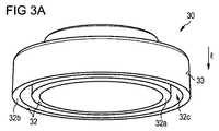
図3A及び3Bは、図1及び2において示された通りのシリンジ1の近位端12に取り付けられたフィンガーフランジの斜視図を示す。本図において、第一のコーディング機構2に適する面が確認される。フィンガーフランジ30が特許文献5において示された通りの開放リングとしても働く場合、フィンガーフランジ30の幾つかの外面はプランジャー5の部分によって覆われ得て、そのようにして外側から必ずしもアクセス可能ではない。フィンガーフランジ30は、同心円的に配置される内部円筒状セクション32a及び外部円筒状セクション32bを含む。内部円筒状セクション32aは外部円筒状セクション32bより小さな直径を有し、そしてスペース32cは、内部円筒状セクション32aと外部円筒状セクション32bの間のフィンガーフランジ30の底面32からアクセスできる。 3A and 3B show perspective views of a finger flange attached to the
好ましくは、第一のコーディング機構2は、外側から常にアクセス可能で、そしてシリンジ1を手動で操作するとき、使用者を邪魔したり気を散らさせたりしないフィンガーフランジ30の一部に置かれる。そのような適当な面は、例えば、シリンジの長手方向軸lから離れて面している側面33である。更に、フィンガーフランジ30の上面31の部分も第一のコーディング機構2に対して好適であり得る。それに加えて、第一のコーディング機構2は内部円筒状セクション32aと外部円筒状セクション32bの間のスペース32c中に置かれ得る。そのような第一のコーディング機構2は、内部円筒状セクション32aから外部円筒状セクション32bに伸びていて、幅と高さが変えられるプラスチックウエブであり得る。第一のコーディング機構2のその付属品の代わりに又はそれに加えて、フィンガーフランジ30の底面32に、例えば、突起又はぎざぎざが置かれ得る。 Preferably, the
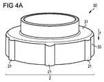
図4Aは、フィンガーフランジ30の側面33に置かれた幾つかのリブ21を含む第一のコーディング機構2を有するフィンガーフランジ30を示す。リブ21はバレル10の長手方向軸lに沿って伸び、そして長手方向軸lの周りの特定の角度を有するスペースに配置される。 FIG. 4A shows a
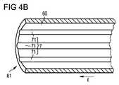
図4Bは、図4において示された通りの第一のコーディング機構に整合する第二のコーディング機構7を有する自己注射デバイス6のハウジング60の内部部分を示す。コーディング機構7は、第一のコーディング機構2の位置に対応する位置に配置される幾つかの溝71を含む。第二のコーディング機構7は、第一のコーディング機構2が第二のコーディング機構7と整合するとき、シリンジ1がハウジング60内にのみ挿入することができるように、ハウジング60の前方端部61から伸びる。そうすることによって、間違ったシリンジ1の挿入が防がれる。 FIG. 4B shows the internal portion of the
別の実施態様において、フィンガーフランジ30及びハウジング60の周辺の周りの変化し得る角度の位置で、多くのリブ21及び溝71が供される。そうすることによって、利用可能なコーディング並べ換えの数を著しく増やすことができる。 In another embodiment, a number of
図5Aは、フィンガーフランジ30の上面31に置かれたリブ21を含む第一のコーディング機構2を有するフィンガーフランジ30の第二の実施態様を示す。 FIG. 5A shows a second embodiment of the
図5Bは、シリンジ固定エレメント8に置かれたスリット72を含むはめ込み(mating)第二のコーディング機構7を有するハウジング60の内部部分を示す。そのような第二のコーディング機構7によって、はめ込まれていない第一のコーディング機構2を有するシリンジ1の完全な組立を防ぐことができて、一方、自己注射デバイス6中へのそのようなシリンジ1の部分的な挿入が可能になる。 FIG. 5B shows the inner part of the
図6Aは、各々第一のコーディング機構2a、2bを含むフィンガーフランジ30a、30bのセットを示す。各第一のコーディング機構2a、2bはフィンガーフランジ30a、30bの側面33a、33bに置かれたリブ21a、21bを含む。リブ21a、21bの配置はフィンガーフランジ30a、30bの間で異なり、それによって第一のコーディング機構2a、2bのコーディング機能が達成される。第一のフィンガーフランジ30aにおいて、リブ21aの角度スペースは第二のフィンガーフランジ30bのリブ21bに対するものより小さい。更に、各フィンガーフランジ30a、30bは第一の配向機構4a、4bを含み、それによって使用者は容易に、シリンジ1を自己注射デバイス6中に挿入するとき、自己注射デバイス6に対するシリンジ1の正しい配向を認識する。第一の配向機構4a、4bは、第一のコーディング機構2a、2bのリブ21a、21bより大きな断面を有するリブである。 FIG. 6A shows a set of
図6Bは、自己注射デバイス6a、6bのハウジング60a、60bの内部部分に置かれた第二のコーディング機構7a、7bのセットを示す。本明細書において、第一の自己注射デバイス6aの第二のコーディング機構7aは、図6Aにおいて示された第一のフィンガーフランジ30aの第一のコーディング機構7aに一致している溝71aを含む。第二の自己注射デバイス6bの第二のコーディング機構7bは、図6Aにおいて示された第二のフィンガーフランジ30bの第一のコーディング機構2bに一致している溝71bを含む。ハウジング60a、bは、図6Aにおいて示された第一の配向機構4a、4bに整合する第二の配向機構9a、9bを含む。 FIG. 6B shows a set of
自己注射デバイス6a、6bの一つにおいて、図6Aにおいて示されたフィンガーフランジ30a、30bの一つを有するシリンジ1を挿入しようとするとき、使用者は最初に第一の配向機構4a、4b及び第二の配向機構9a、9bを並べるであろう。次いで、使用者は即座に第一のコーディング機構2a、2bが第二のコーディング機構9a、9bと整合するか否かを認識し、その結果、シリンジ1が或る自己注射デバイス6a、6bに取付け可能であるか否かを認識する。 In one of the self-
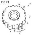
図7Aは第一のコーディング機構2及び第一の配向機構4を有するフィンガーフランジ30の更なる実施態様を示す。第一のコーディング機構2は、フィンガーフランジ30の側面33に置かれた溝24を含む。コーディング機能は溝24の数及び角度分布によって供される。更に、フィンガーフランジ30の側面33に、長手方向軸lに沿って伸びているリブの形態の第一の配向機構4が置かれる。 FIG. 7A shows a further embodiment of a
溝24の数及び角度分布を変えることによって、各々が特定の薬物製品に対する特定のコードを有する複数のフィンガーフランジ30を供することができる。薬物製品で事前に充填されたシリンジにコード化されたフィンガーフランジ30を取り付けることによって、シリンジのコーディングを達成することができる。 By varying the number and angular distribution of
図7Bは、図7Aに記載のフィンガーフランジ30の第一のコーディング機構2に整合する、第二のコーディング機構7を有する自己注射デバイス6のハウジング60を示す。第二のコーディング機構7は、ハウジング60の内部部分の前方端部61からその後方端部62に向かって伸びている複数のリブ76を含む。更に、ハウジング6は、フィンガーフランジ30の第一の配向機構4と整合する第二の配向機構9を含む。第二の配向機構9は溝の形態を有し、その中に第一の配向機構4のリブを収容することができる。 FIG. 7B shows a
図7Cは、図7Bに記載の自己注射デバイスのハウジング中に挿入された、図7Aに記載のフィンガーフランジ30を示す。フィンガーフランジ30はシリンジバレル10の近位端12に取り付けられる。簡明を期すために、本図においてシリンジ1は示されない。 FIG. 7C shows the
図8は、第一のコーディング機構2及び第一の配向機構4を有するフィンガーフランジ30の更なる実施態様を示す。第一のコーディング機構2は、フィンガーフランジ30の最上面31に置かれた幾つかの溝24を含む。コーディング機能は溝24の数及び角度分布によって供される。更に、フィンガーフランジ30の側面33に、長手方向軸lに沿って伸びているリブの形態の第一の配向機構4が置かれる。 FIG. 8 shows a further embodiment of a
好ましくは、溝24の角度分布又は数が異なっている複数のフィンガーフランジ30が供され、それによって各第一のコーディング機構2は特定の薬物製品をコード化する。 Preferably, a plurality of
図9は、第一のコーディング機構2及び第一の配向機構4を有するフィンガーフランジ30の更なる実施態様を示す。第一のコーディング機構2は、内部円筒状セクション32aと外部円筒状セクション32bの間のスペース32cに置かれた幾つかのバー25を含む。バー25は内部円筒状セクション32aから外部円筒状セクション32bに向かって伸びる。コーディング機能はバー25の数及び角度分布によって供される。更に、フィンガーフランジ30の側面33に、長手方向軸lに沿って伸びているリブの形態の第一の配向機構4が置かれる。 FIG. 9 shows a further embodiment of a
好ましくは、バー25の角度分布又は数が異なっている複数のフィンガーフランジ30が供され、それによって各第一のコーディング機構2は特定の薬物製品をコード化する。同様に、第二のコーディング機構7を有する複数の自己注射デバイス6が供され、それによって各第二のコーディング機構7は特定の薬物製品をコード化する。特定の薬物製品を含有するシリンジ1にフィンガーフランジ30を取り付けることによって、もし第一のコーディング機構2及び第二のコーディング機構7が整合する場合にのみシリンジ1が自己注射デバイス6中に取付け可能であるように、シリンジ1と自己注射デバイス6の間のマッピングが達成することができる。 Preferably, a plurality of
図10は、第一のコーディング機構2及び第一の配向機構4を有するフィンガーフランジ30の更なる実施態様示す。第一のコーディング機構2は外部円筒状セクション32bの底面32に置かれた幾つかのスリット26を含む。コーディング機能はスリット26の数及び角度分布によって供される。更に、フィンガーフランジ30の側面33に、長手方向軸lに沿って伸びているリブの形態の第一の配向機構4が置かれる。 FIG. 10 shows a further embodiment of a
好ましくは、スリット26の角度分布又は数が異なっている複数のフィンガーフランジ30が供され、それによって各第一のコーディング機構2は特定の薬物製品をコード化する。 Preferably, a plurality of
1シリンジ
10バレル
11遠位端
12近位端
13針
2、2a、2b第一のコーディング機構
21、21a、21bリブ
24溝
25バー
26スリット
3エレメント
30フィンガーフランジ
31上面
32底面
32a内部円筒状セクション
32b外部円筒状セクション
32c円筒状セクションの間のスペース
33、33a、33b、33b側面
4、4a、4b第一の配向機構
5プランジャー
51ボタン
52プランジャーシール
6、6a、6b自己注射デバイス
60、60a、60bハウジング
61前方端部
62後方端部
63膜
64起動手段
7、7a、7b第二のコーディング機構
71、71a、71b溝
72スリット
76リブ
8固定エレメント
9、9a、9b第二の配向機構
l 長手方向軸1
Claims (12)
Translated fromJapaneseバレル(10)の近位端(12)近くに位置するフィンガーフランジ(30)、及び
自己注射デバイス(6)の第二のコーディング機構(7、7a、7b)との機械的相互作用のための第一のコーディング機構(2、2a、2b)、その第一コーディング機構(2,2a,2b)がフィンガーフランジ(30)に位置している、
を含むシリンジであって、
ここで、第一のコーディング機構(2、2a、2b)は、第一(2、2a、2b)及び第二のコーディング機構(7、7a、7b)が整合する場合にのみ、シリンジ(1)が第二のコーディング機構(7、7a、7b)を有する自己注射デバイス(6)中に取付け可能であるように設計される、上記シリンジ。Barrel (10) containing the drug,
For mechanical interaction with thefinger flange (30) located near the proximal end (12) of the barrel (10) and the second coding mechanism (7, 7a, 7b) of the self-injection device (6) The first coding mechanism (2, 2a, 2b), the first coding mechanism (2, 2a, 2b) is located on the finger flange (30),
A syringe comprising
Here, the first coding mechanism (2, 2a, 2b) is the syringe (1) only when the first (2, 2a, 2b) and the second coding mechanism (7, 7a, 7b) are aligned. Said syringe designed to be attachable in a self-injection device (6) having a second coding mechanism (7, 7a, 7b).
第一のコーディング機構(2、2a、2b)が、リブ(21、21a、21b)、バー(25)、ピン、突起、溝(24)、スリット(26)、ぎざぎざ、キー溝、段付直径及び角を成す平面のグループから選ばれる少なくとも一つの付属物を含む、上記シリンジ。The syringe accordingto claim1 ,
The first coding mechanism (2, 2a, 2b) has ribs (21, 21a, 21b), bars (25), pins, protrusions, grooves (24), slits (26), jagged edges, key grooves, stepped diameters. And at least one appendage selected from the group of angular planes.
長手方向軸(l)を有し、
ここで第一のコーディング機構(2、2a、2b)が、長手方向軸に向かって伸びる複数のリブ(21、21a、21b)を含む、上記シリンジ。The syringe according to claim 1or 2 ,
Having a longitudinal axis (l),
The syringe, wherein the first coding mechanism (2, 2a, 2b) includes a plurality of ribs (21, 21a, 21b) extending toward the longitudinal axis.
シリンジ(1)が、自己注射デバイス(6)内へのシリンジ(1)の取付け中に、シリンジ(1)の配向を規定する第一の配向機構(4a、4b)を含む、上記シリンジ。The syringe according to claim3 , wherein
Said syringe, wherein the syringe (1) comprises a first orientation mechanism (4a, 4b) that defines the orientation of the syringe (1) during attachment of the syringe (1) into the self-injection device (6).
請求項1〜4の何れか1項に記載のシリンジ(1)を取付けすることができるハウジング(60、60a、60b);及び
シリンジ(1)の第一のコーディング機構(2、2a、2b)との機械的相互作用のための第二のコーディング機構(7、7a、7b);
を含む、上記自己注射デバイス。Self-injection device:
A housing (60, 60a, 60b) to which the syringe (1) according to any one of claims 1 to4 can be mounted; and a first coding mechanism (2, 2a, 2b) of the syringe (1) A second coding mechanism for mechanical interaction with (7, 7a, 7b);
Including the self-injection device.
第二のコーディング機構(7、7a、7b)が、第二のコーディング機構(2、2a、2b)と嵌め合う第一のコーディング機構を有するシリンジ(1)のみが自己注射デバイス(6)で完全に組立てられ得るように設計される、上記自己注射デバイス。A self-injection device according to claim5 ,
Only the syringe (1) with the first coding mechanism where the second coding mechanism (7, 7a, 7b) mates with the second coding mechanism (2, 2a, 2b) is complete with the self-injection device (6) A self-injection device as described above, designed to be assembled into.
第二のコーディング機構(7、7a、7b)がシリンジ固定エレメント(8)の近くに位置する、上記自己注射デバイス。The self-injection device according to claim6 ,
Said self-injection device, wherein the second coding mechanism (7, 7a, 7b) is located near the syringe anchoring element (8).
第二のコーディング機構(7、7a、7b)が、第二のコーディング機構(7、7a、7b)と嵌め合う第一のコーディング機構(2、2a、2b)を有するシリンジ(1)のみがハウジング(60、60a、60b)内に挿入され得るように設計される、上記自己注射デバイス。The self-injection device according to any one of claims5 to 7 ,
Only the syringe (1) having the first coding mechanism (2, 2a, 2b) in which the second coding mechanism (7, 7a, 7b) is fitted with the second coding mechanism (7, 7a, 7b) is a housing. The self-injection device designed to be inserted into (60, 60a, 60b).
第二のコーディング機構(7、7a、7b)がハウジング(60、60a、60b)の前端部(61)近くに位置する、上記自己注射デバイス。A self-injection device according to claim8 ,
Said self-injection device, wherein the second coding mechanism (7, 7a, 7b) is located near the front end (61) of the housing (60, 60a, 60b).
シリンジ(1)が交換可能である、上記自己注射デバイス。A self-injection device according to claim9 ,
Said self-injection device, wherein the syringe (1) is replaceable.
それぞれの第二のコーディング機構(7、7a、7b)との機械的相互作用の故に、各シリンジ(1)が自己注射デバイス(6)の一方のみに取付け可能であるように、各シリンジ(1)に対して第一のコーディング機構(2、2a、2b)が設計される、上記セット。A set of at least two self-injection devices according to any one of claims5 to 10 , and at least two syringes according to any one of claims1-4 .
Each syringe (1) so that, due to mechanical interaction with the respective second coding mechanism (7, 7a, 7b), each syringe (1) can only be attached to one of the self-injection devices (6). ) For which the first coding mechanism (2, 2a, 2b) is designed.
各シリンジ(1)に対して、第一のコーディング機構(2、2a、2b)が、シリンジ(1)中に含有された特定の薬剤をコード化する、上記セット。The set according to claim11 , wherein
The above set, wherein for each syringe (1), the first coding mechanism (2, 2a, 2b) encodes the particular drug contained in the syringe (1).
Applications Claiming Priority (3)
| Application Number | Priority Date | Filing Date | Title |
|---|---|---|---|
| EP09003281 | 2009-03-06 | ||
| EP09003281.4 | 2009-03-06 | ||
| PCT/EP2010/052791WO2010100246A1 (en) | 2009-03-06 | 2010-03-04 | Syringe, auto-injector device and set of auto-injector devices and syringes |
Publications (2)
| Publication Number | Publication Date |
|---|---|
| JP2012519514A JP2012519514A (en) | 2012-08-30 |
| JP5570534B2true JP5570534B2 (en) | 2014-08-13 |
Family
ID=40785510
Family Applications (1)
| Application Number | Title | Priority Date | Filing Date |
|---|---|---|---|
| JP2011552458AExpired - Fee RelatedJP5570534B2 (en) | 2009-03-06 | 2010-03-04 | Syringe, self-injection device, and set of self-injection device and syringe |
Country Status (7)
| Country | Link |
|---|---|
| US (1) | US8708975B2 (en) |
| EP (1) | EP2403561B1 (en) |
| JP (1) | JP5570534B2 (en) |
| AU (1) | AU2010220260B2 (en) |
| CA (1) | CA2753959A1 (en) |
| DK (1) | DK2403561T3 (en) |
| WO (1) | WO2010100246A1 (en) |
Families Citing this family (30)
| Publication number | Priority date | Publication date | Assignee | Title |
|---|---|---|---|---|
| WO2003068290A2 (en) | 2002-02-11 | 2003-08-21 | Antares Pharma, Inc. | Intradermal injector |
| HUE042286T2 (en) | 2005-01-24 | 2019-06-28 | Antares Pharma Inc | Needle-filled pre-filled syringe |
| WO2007131013A1 (en) | 2006-05-03 | 2007-11-15 | Antares Pharma, Inc. | Two-stage reconstituting injector |
| WO2007131025A1 (en) | 2006-05-03 | 2007-11-15 | Antares Pharma, Inc. | Injector with adjustable dosing |
| EP3636301A1 (en) | 2008-03-10 | 2020-04-15 | Antares Pharma, Inc. | Injector safety device |
| US8376993B2 (en) | 2008-08-05 | 2013-02-19 | Antares Pharma, Inc. | Multiple dosage injector |
| CA2807216A1 (en)* | 2010-08-13 | 2012-02-16 | Sanofi-Aventis Deutschland Gmbh | Coding system for a drug delivery device and drug delivery system |
| WO2012020088A2 (en)* | 2010-08-13 | 2012-02-16 | Sanofi-Aventis Deutschland Gmbh | Coded cartridge assembly |
| US9173999B2 (en) | 2011-01-26 | 2015-11-03 | Kaleo, Inc. | Devices and methods for delivering medicaments from a multi-chamber container |
| US8496619B2 (en) | 2011-07-15 | 2013-07-30 | Antares Pharma, Inc. | Injection device with cammed ram assembly |
| US9220660B2 (en) | 2011-07-15 | 2015-12-29 | Antares Pharma, Inc. | Liquid-transfer adapter beveled spike |
| US9486583B2 (en) | 2012-03-06 | 2016-11-08 | Antares Pharma, Inc. | Prefilled syringe with breakaway force feature |
| EP4186545A1 (en) | 2012-04-06 | 2023-05-31 | Antares Pharma, Inc. | Needle assisted jet injection administration of testosterone compositions |
| US9364610B2 (en) | 2012-05-07 | 2016-06-14 | Antares Pharma, Inc. | Injection device with cammed ram assembly |
| US9227019B2 (en) | 2012-08-29 | 2016-01-05 | Amgen Inc. | Pre-filled syringe identification tag |
| BR112015010607A2 (en) | 2012-11-09 | 2017-12-05 | Iinjec Tech Inc | fluid delivery injector, retractable needle assembly, and method for injecting at least one dose of a transcutaneously fluid medication into the body. |
| USD749211S1 (en)* | 2012-12-14 | 2016-02-09 | Conmed Corporation | Keyway portion |
| FI3659647T3 (en) | 2013-02-11 | 2024-03-28 | Antares Pharma Inc | NEEDLE-ASSISTED SPRAY INJECTOR WITH REDUCED TRIGGER FORCE |
| CA2905031C (en) | 2013-03-11 | 2018-01-23 | Hans PFLAUMER | Dosage injector with pinion system |
| EP2902062A1 (en)* | 2014-01-30 | 2015-08-05 | Sanofi-Aventis Deutschland GmbH | Medicament delivery device |
| US9517307B2 (en) | 2014-07-18 | 2016-12-13 | Kaleo, Inc. | Devices and methods for delivering opioid antagonists including formulations for naloxone |
| CA2990950A1 (en) | 2015-06-30 | 2017-01-05 | Kaleo, Inc. | Auto-injectors for administration of a medicament within a prefilled syringe |
| US11083837B2 (en) | 2016-03-22 | 2021-08-10 | International Business Machines Corporation | Secure medication delivery |
| US10376444B2 (en) | 2016-03-22 | 2019-08-13 | International Business Machines Corporation | Secure medication delivery |
| US20170274145A1 (en)* | 2016-03-22 | 2017-09-28 | International Business Machines Corporation | Secure medication delivery |
| WO2018119218A1 (en) | 2016-12-23 | 2018-06-28 | Kaleo, Inc. | Medicament delivery device and methods for delivering drugs to infants and children |
| CA3145580A1 (en) | 2019-08-09 | 2021-02-18 | Kaleo, Inc. | Devices and methods for delivery of substances within a prefilled syringe |
| AU2019466785A1 (en)* | 2019-09-19 | 2022-03-31 | Cc Biotechnology Corporation | Common injection device |
| AU2020399217A1 (en)* | 2019-12-11 | 2022-07-28 | Sanofi | Electronic module and modular system for a drug delivery device |
| US12268847B1 (en) | 2021-02-10 | 2025-04-08 | Kaleo, Inc. | Devices and methods for delivery of substances within a medicament container |
Family Cites Families (16)
| Publication number | Priority date | Publication date | Assignee | Title |
|---|---|---|---|---|
| US5336200A (en)* | 1992-03-10 | 1994-08-09 | Injectimed, Inc. | Retractable sleeve-protection for injection apparatus employing carpules |
| FR2733155B1 (en) | 1995-04-18 | 1997-09-19 | Tebro | RECHARGEABLE SELF-INJECTOR |
| JP4593714B2 (en)* | 2000-02-10 | 2010-12-08 | 株式会社根本杏林堂 | Syringe outer cylinder, syringe holder, syringe piston and piston holder |
| WO2002081011A1 (en)* | 2001-04-03 | 2002-10-17 | Medrad, Inc. | Encoding and sensing of syringe information |
| JP2005000203A (en) | 2003-06-09 | 2005-01-06 | Nemoto Kyorindo:Kk | Liquid medication injection system |
| DE102004009434A1 (en)* | 2004-02-24 | 2005-12-15 | Boehringer Ingelheim International Gmbh | atomizer |
| US7297136B2 (en) | 2004-12-06 | 2007-11-20 | Wyrick Ronald E | Medicine injection devices and methods |
| EP1912135B1 (en) | 2005-04-06 | 2010-09-15 | Mallinckrodt, Inc. | System and methods for managing information relating to medical fluids and containers therefor |
| US20070197978A1 (en)* | 2006-02-17 | 2007-08-23 | Leon Wortham | Drug Delivery Device |
| US8257286B2 (en) | 2006-09-21 | 2012-09-04 | Tyco Healthcare Group Lp | Safety connector apparatus |
| EP2083888A1 (en)* | 2006-11-17 | 2009-08-05 | Novo Nordisk A/S | A medical delivery system comprising a coding mechanism between dosing assembly and medicament container |
| ES2365931T3 (en) | 2006-12-13 | 2011-10-13 | Shl Group Ab | AUTOMATIC INJECTOR |
| EP2091598B1 (en)* | 2006-12-15 | 2012-07-11 | Novo Nordisk A/S | A medical delivery system comprising a container and a dosing assembly with radially moving fastening means |
| WO2008074897A1 (en)* | 2006-12-21 | 2008-06-26 | Novo Nordisk A/S | A syringe device |
| GB0704351D0 (en) | 2007-03-07 | 2007-04-11 | Medical House Plc The | Improved autoinjector |
| NZ595031A (en) | 2007-07-02 | 2012-02-24 | Unitract Syringe Pty Ltd | Automatically retracting syringe with spring based mechanisim |
- 2010
- 2010-03-04JPJP2011552458Apatent/JP5570534B2/ennot_activeExpired - Fee Related
- 2010-03-04WOPCT/EP2010/052791patent/WO2010100246A1/enactiveApplication Filing
- 2010-03-04DKDK10707024.5Tpatent/DK2403561T3/enactive
- 2010-03-04EPEP10707024.5Apatent/EP2403561B1/enactiveActive
- 2010-03-04AUAU2010220260Apatent/AU2010220260B2/ennot_activeCeased
- 2010-03-04CACA2753959Apatent/CA2753959A1/ennot_activeAbandoned
- 2010-03-04USUS13/202,441patent/US8708975B2/ennot_activeExpired - Fee Related
Also Published As
| Publication number | Publication date |
|---|---|
| WO2010100246A1 (en) | 2010-09-10 |
| US20120101446A1 (en) | 2012-04-26 |
| JP2012519514A (en) | 2012-08-30 |
| EP2403561B1 (en) | 2017-10-18 |
| DK2403561T3 (en) | 2018-01-22 |
| US8708975B2 (en) | 2014-04-29 |
| CA2753959A1 (en) | 2010-09-10 |
| AU2010220260A1 (en) | 2011-09-22 |
| EP2403561A1 (en) | 2012-01-11 |
| AU2010220260B2 (en) | 2014-07-24 |
Similar Documents
| Publication | Publication Date | Title |
|---|---|---|
| JP5570534B2 (en) | Syringe, self-injection device, and set of self-injection device and syringe | |
| JP5828886B2 (en) | Coded cap for use with drug delivery devices | |
| JP5956978B2 (en) | Coded connecting element with bendable locking element for drug reservoir | |
| JP5674770B2 (en) | Drive mechanism for a drug delivery device | |
| JP5968869B2 (en) | Encoded drug reservoir connection element with hinged flange | |
| JP5782432B2 (en) | Biasing mechanism for a cartridge of a drug delivery device | |
| JP5659231B2 (en) | Reminder device for drug delivery device | |
| JP5820808B2 (en) | Dose setting mechanism for priming drug delivery devices | |
| US8911402B2 (en) | Drug delivery device | |
| JP5744013B2 (en) | Dose setting mechanism for drug delivery devices | |
| JP5718341B2 (en) | Arrangement for use in a drug delivery device | |
| JP6177686B2 (en) | Cartridge assembly and drug delivery device having shared fastening means | |
| JP5813097B2 (en) | Coded cartridge holder system for fluid delivery devices | |
| JP5784702B2 (en) | Coded keying insert for drug cartridge | |
| CN102573961B (en) | Drive mechanism for drug delivery device | |
| JP5814244B2 (en) | Drug delivery device | |
| JP6200326B2 (en) | Mechanisms to prevent dose selection | |
| JP2013533078A (en) | Identification for drug delivery devices | |
| JP2014502872A (en) | Drug delivery device with housing comprising a fragile zone |
Legal Events
| Date | Code | Title | Description |
|---|---|---|---|
| A621 | Written request for application examination | Free format text:JAPANESE INTERMEDIATE CODE: A621 Effective date:20130221 | |
| A131 | Notification of reasons for refusal | Free format text:JAPANESE INTERMEDIATE CODE: A131 Effective date:20140128 | |
| A521 | Request for written amendment filed | Free format text:JAPANESE INTERMEDIATE CODE: A523 Effective date:20140425 | |
| TRDD | Decision of grant or rejection written | ||
| A01 | Written decision to grant a patent or to grant a registration (utility model) | Free format text:JAPANESE INTERMEDIATE CODE: A01 Effective date:20140527 | |
| A61 | First payment of annual fees (during grant procedure) | Free format text:JAPANESE INTERMEDIATE CODE: A61 Effective date:20140624 | |
| R150 | Certificate of patent or registration of utility model | Ref document number:5570534 Country of ref document:JP Free format text:JAPANESE INTERMEDIATE CODE: R150 | |
| LAPS | Cancellation because of no payment of annual fees |