JP5570533B2 - Needle unit - Google Patents
Needle unitDownload PDFInfo
- Publication number
- JP5570533B2 JP5570533B2JP2011552455AJP2011552455AJP5570533B2JP 5570533 B2JP5570533 B2JP 5570533B2JP 2011552455 AJP2011552455 AJP 2011552455AJP 2011552455 AJP2011552455 AJP 2011552455AJP 5570533 B2JP5570533 B2JP 5570533B2
- Authority
- JP
- Japan
- Prior art keywords
- needle
- stop member
- drug delivery
- delivery device
- unit
- Prior art date
- Legal status (The legal status is an assumption and is not a legal conclusion. Google has not performed a legal analysis and makes no representation as to the accuracy of the status listed.)
- Expired - Fee Related
Links
- 238000012377drug deliveryMethods0.000claimsdescription71
- 239000003814drugSubstances0.000claimsdescription27
- 239000006223plastic coatingSubstances0.000claimsdescription2
- 229940090048pen injectorDrugs0.000claims1
- JUFFVKRROAPVBI-PVOYSMBESA-Nchembl1210015Chemical compoundC([C@@H](C(=O)N[C@@H]([C@@H](C)CC)C(=O)N[C@@H](CCC(O)=O)C(=O)N[C@@H](CC=1C2=CC=CC=C2NC=1)C(=O)N[C@@H](CC(C)C)C(=O)N[C@@H](CCCCN)C(=O)N[C@@H](CC(=O)N[C@H]1[C@@H]([C@@H](O)[C@H](O[C@H]2[C@@H]([C@@H](O)[C@@H](O)[C@@H](CO[C@]3(O[C@@H](C[C@H](O)[C@H](O)CO)[C@H](NC(C)=O)[C@@H](O)C3)C(O)=O)O2)O)[C@@H](CO)O1)NC(C)=O)C(=O)NCC(=O)NCC(=O)N1[C@@H](CCC1)C(=O)N[C@@H](CO)C(=O)N[C@@H](CO)C(=O)NCC(=O)N[C@@H](C)C(=O)N1[C@@H](CCC1)C(=O)N1[C@@H](CCC1)C(=O)N1[C@@H](CCC1)C(=O)N[C@@H](CO)C(N)=O)NC(=O)[C@H](CC(C)C)NC(=O)[C@H](CCCNC(N)=N)NC(=O)[C@@H](NC(=O)[C@H](C)NC(=O)[C@H](CCC(O)=O)NC(=O)[C@H](CCC(O)=O)NC(=O)[C@H](CCC(O)=O)NC(=O)[C@H](CCSC)NC(=O)[C@H](CCC(N)=O)NC(=O)[C@H](CCCCN)NC(=O)[C@H](CO)NC(=O)[C@H](CC(C)C)NC(=O)[C@H](CC(O)=O)NC(=O)[C@H](CO)NC(=O)[C@@H](NC(=O)[C@H](CC=1C=CC=CC=1)NC(=O)[C@@H](NC(=O)CNC(=O)[C@H](CCC(O)=O)NC(=O)CNC(=O)[C@@H](N)CC=1NC=NC=1)[C@@H](C)O)[C@@H](C)O)C(C)C)C1=CC=CC=C1JUFFVKRROAPVBI-PVOYSMBESA-N0.000description82
- 230000000712assemblyEffects0.000description49
- 238000000429assemblyMethods0.000description49
- 108010011459ExenatideProteins0.000description44
- 229960001519exenatideDrugs0.000description44
- 229940079593drugDrugs0.000description26
- 101000976075Homo sapiens InsulinProteins0.000description22
- PBGKTOXHQIOBKM-FHFVDXKLSA-Ninsulin (human)Chemical compoundC([C@@H](C(=O)N[C@@H](CC(C)C)C(=O)N[C@H]1CSSC[C@H]2C(=O)N[C@H](C(=O)N[C@@H](CO)C(=O)N[C@H](C(=O)N[C@H](C(N[C@@H](CO)C(=O)N[C@@H](CC(C)C)C(=O)N[C@@H](CC=3C=CC(O)=CC=3)C(=O)N[C@@H](CCC(N)=O)C(=O)N[C@@H](CC(C)C)C(=O)N[C@@H](CCC(O)=O)C(=O)N[C@@H](CC(N)=O)C(=O)N[C@@H](CC=3C=CC(O)=CC=3)C(=O)N[C@@H](CSSC[C@H](NC(=O)[C@H](C(C)C)NC(=O)[C@H](CC(C)C)NC(=O)[C@H](CC=3C=CC(O)=CC=3)NC(=O)[C@H](CC(C)C)NC(=O)[C@H](C)NC(=O)[C@H](CCC(O)=O)NC(=O)[C@H](C(C)C)NC(=O)[C@H](CC(C)C)NC(=O)[C@H](CC=3NC=NC=3)NC(=O)[C@H](CO)NC(=O)CNC1=O)C(=O)NCC(=O)N[C@@H](CCC(O)=O)C(=O)N[C@@H](CCCNC(N)=N)C(=O)NCC(=O)N[C@@H](CC=1C=CC=CC=1)C(=O)N[C@@H](CC=1C=CC=CC=1)C(=O)N[C@@H](CC=1C=CC(O)=CC=1)C(=O)N[C@@H]([C@@H](C)O)C(=O)N1[C@@H](CCC1)C(=O)N[C@@H](CCCCN)C(=O)N[C@@H]([C@@H](C)O)C(O)=O)C(=O)N[C@@H](CC(N)=O)C(O)=O)=O)CSSC[C@@H](C(N2)=O)NC(=O)[C@H](CCC(N)=O)NC(=O)[C@H](CCC(O)=O)NC(=O)[C@H](C(C)C)NC(=O)[C@@H](NC(=O)CN)[C@@H](C)CC)[C@@H](C)CC)[C@@H](C)O)NC(=O)[C@H](CCC(N)=O)NC(=O)[C@H](CC(N)=O)NC(=O)[C@@H](NC(=O)[C@@H](N)CC=1C=CC=CC=1)C(C)C)C1=CN=CN1PBGKTOXHQIOBKM-FHFVDXKLSA-N0.000description22
- 150000003839saltsChemical class0.000description9
- 150000001875compoundsChemical class0.000description7
- 238000002347injectionMethods0.000description5
- 239000007924injectionSubstances0.000description5
- -1antibodyProteins0.000description4
- 229920001971elastomerPolymers0.000description4
- 239000012530fluidSubstances0.000description4
- 238000004519manufacturing processMethods0.000description4
- 108090000765processed proteins & peptidesProteins0.000description4
- 230000000903blocking effectEffects0.000description3
- 206010012601diabetes mellitusDiseases0.000description3
- 150000004676glycansChemical class0.000description3
- 239000003055low molecular weight heparinSubstances0.000description3
- 229940127215low-molecular weight heparinDrugs0.000description3
- 230000007246mechanismEffects0.000description3
- 229920001282polysaccharidePolymers0.000description3
- 239000005017polysaccharideSubstances0.000description3
- 208000004476Acute Coronary SyndromeDiseases0.000description2
- 206010012689Diabetic retinopathyDiseases0.000description2
- 108010088406Glucagon-Like PeptidesProteins0.000description2
- 102000006771GonadotropinsHuman genes0.000description2
- 108010086677GonadotropinsProteins0.000description2
- 102000002265Human Growth HormoneHuman genes0.000description2
- 108010000521Human Growth HormoneProteins0.000description2
- 239000000854Human Growth HormoneSubstances0.000description2
- 239000002253acidSubstances0.000description2
- 229910052784alkaline earth metalInorganic materials0.000description2
- 239000002585baseChemical class0.000description2
- 239000000806elastomerSubstances0.000description2
- 239000002622gonadotropinSubstances0.000description2
- 229940088597hormoneDrugs0.000description2
- 239000005556hormoneSubstances0.000description2
- 239000000463materialSubstances0.000description2
- 230000013011matingEffects0.000description2
- 230000002265preventionEffects0.000description2
- 239000007787solidSubstances0.000description2
- 239000012453solvateSubstances0.000description2
- 229960004532somatropinDrugs0.000description2
- KIUKXJAPPMFGSW-DNGZLQJQSA-N(2S,3S,4S,5R,6R)-6-[(2S,3R,4R,5S,6R)-3-Acetamido-2-[(2S,3S,4R,5R,6R)-6-[(2R,3R,4R,5S,6R)-3-acetamido-2,5-dihydroxy-6-(hydroxymethyl)oxan-4-yl]oxy-2-carboxy-4,5-dihydroxyoxan-3-yl]oxy-5-hydroxy-6-(hydroxymethyl)oxan-4-yl]oxy-3,4,5-trihydroxyoxane-2-carboxylic acidChemical compoundCC(=O)N[C@H]1[C@H](O)O[C@H](CO)[C@@H](O)[C@@H]1O[C@H]1[C@H](O)[C@@H](O)[C@H](O[C@H]2[C@@H]([C@@H](O[C@H]3[C@@H]([C@@H](O)[C@H](O)[C@H](O3)C(O)=O)O)[C@H](O)[C@@H](CO)O2)NC(C)=O)[C@@H](C(O)=O)O1KIUKXJAPPMFGSW-DNGZLQJQSA-N0.000description1
- 125000004169(C1-C6) alkyl groupChemical group0.000description1
- 125000001831(C6-C10) heteroaryl groupChemical group0.000description1
- 208000030507AIDSDiseases0.000description1
- 208000035285Allergic Seasonal RhinitisDiseases0.000description1
- QGZKDVFQNNGYKY-UHFFFAOYSA-OAmmoniumChemical compound[NH4+]QGZKDVFQNNGYKY-UHFFFAOYSA-O0.000description1
- 206010002383Angina PectorisDiseases0.000description1
- 201000001320AtherosclerosisDiseases0.000description1
- 108010037003BuserelinProteins0.000description1
- 125000000882C2-C6 alkenyl groupChemical group0.000description1
- 108010041986DNA VaccinesProteins0.000description1
- 108010000437Deamino Arginine VasopressinProteins0.000description1
- 208000002249Diabetes ComplicationsDiseases0.000description1
- 206010012655Diabetic complicationsDiseases0.000description1
- 208000005189EmbolismDiseases0.000description1
- 102000004190EnzymesHuman genes0.000description1
- 108090000790EnzymesProteins0.000description1
- 102400000932Gonadoliberin-1Human genes0.000description1
- 108010069236GoserelinProteins0.000description1
- BLCLNMBMMGCOAS-URPVMXJPSA-NGoserelinChemical compoundC([C@@H](C(=O)N[C@H](COC(C)(C)C)C(=O)N[C@@H](CC(C)C)C(=O)N[C@@H](CCCN=C(N)N)C(=O)N1[C@@H](CCC1)C(=O)NNC(N)=O)NC(=O)[C@H](CO)NC(=O)[C@H](CC=1C2=CC=CC=C2NC=1)NC(=O)[C@H](CC=1NC=NC=1)NC(=O)[C@H]1NC(=O)CC1)C1=CC=C(O)C=C1BLCLNMBMMGCOAS-URPVMXJPSA-N0.000description1
- HTTJABKRGRZYRN-UHFFFAOYSA-NHeparinChemical compoundOC1C(NC(=O)C)C(O)OC(COS(O)(=O)=O)C1OC1C(OS(O)(=O)=O)C(O)C(OC2C(C(OS(O)(=O)=O)C(OC3C(C(O)C(O)C(O3)C(O)=O)OS(O)(=O)=O)C(CO)O2)NS(O)(=O)=O)C(C(O)=O)O1HTTJABKRGRZYRN-UHFFFAOYSA-N0.000description1
- 101500026183Homo sapiens Gonadoliberin-1Proteins0.000description1
- UFHFLCQGNIYNRP-UHFFFAOYSA-NHydrogenChemical compound[H][H]UFHFLCQGNIYNRP-UHFFFAOYSA-N0.000description1
- 108010024118Hypothalamic HormonesProteins0.000description1
- 102000015611Hypothalamic HormonesHuman genes0.000description1
- 206010061218InflammationDiseases0.000description1
- 206010069803Injury associated with deviceDiseases0.000description1
- 108010000817LeuprolideProteins0.000description1
- 102000009151Luteinizing HormoneHuman genes0.000description1
- 108010073521Luteinizing HormoneProteins0.000description1
- 108010021717NafarelinProteins0.000description1
- 206010028980NeoplasmDiseases0.000description1
- 108091034117OligonucleotideProteins0.000description1
- 108010047386Pituitary HormonesProteins0.000description1
- 102000006877Pituitary HormonesHuman genes0.000description1
- ONIBWKKTOPOVIA-UHFFFAOYSA-NProlineNatural productsOC(=O)C1CCCN1ONIBWKKTOPOVIA-UHFFFAOYSA-N0.000description1
- 208000010378Pulmonary EmbolismDiseases0.000description1
- 208000001435ThromboembolismDiseases0.000description1
- 108010050144Triptorelin PamoateProteins0.000description1
- 208000027418Wounds and injuryDiseases0.000description1
- 239000003513alkaliSubstances0.000description1
- 150000001342alkaline earth metalsChemical class0.000description1
- 239000005557antagonistSubstances0.000description1
- 125000003118aryl groupChemical group0.000description1
- 229960002719buserelinDrugs0.000description1
- CUWODFFVMXJOKD-UVLQAERKSA-NbuserelinChemical compoundCCNC(=O)[C@@H]1CCCN1C(=O)[C@H](CCCN=C(N)N)NC(=O)[C@H](CC(C)C)NC(=O)[C@@H](COC(C)(C)C)NC(=O)[C@@H](NC(=O)[C@H](CO)NC(=O)[C@H](CC=1C2=CC=CC=C2NC=1)NC(=O)[C@H](CC=1NC=NC=1)NC(=O)[C@H]1NC(=O)CC1)CC1=CC=C(O)C=C1CUWODFFVMXJOKD-UVLQAERKSA-N0.000description1
- 201000011510cancerDiseases0.000description1
- 150000001768cationsChemical class0.000description1
- 230000006378damageEffects0.000description1
- 230000001419dependent effectEffects0.000description1
- 229960004281desmopressinDrugs0.000description1
- NFLWUMRGJYTJIN-NXBWRCJVSA-NdesmopressinChemical compoundC([C@H]1C(=O)N[C@H](C(N[C@@H](CC(N)=O)C(=O)N[C@@H](CSSCCC(=O)N[C@@H](CC=2C=CC(O)=CC=2)C(=O)N1)C(=O)N1[C@@H](CCC1)C(=O)N[C@@H](CCCNC(N)=N)C(=O)NCC(N)=O)=O)CCC(=O)N)C1=CC=CC=C1NFLWUMRGJYTJIN-NXBWRCJVSA-N0.000description1
- 201000010099diseaseDiseases0.000description1
- 208000037265diseases, disorders, signs and symptomsDiseases0.000description1
- 239000013013elastic materialSubstances0.000description1
- 239000013536elastomeric materialSubstances0.000description1
- 239000011521glassSubstances0.000description1
- 229960001442gonadorelinDrugs0.000description1
- XLXSAKCOAKORKW-AQJXLSMYSA-NgonadorelinChemical compoundC([C@@H](C(=O)NCC(=O)N[C@@H](CC(C)C)C(=O)N[C@@H](CCCNC(N)=N)C(=O)N1[C@@H](CCC1)C(=O)NCC(N)=O)NC(=O)[C@H](CO)NC(=O)[C@H](CC=1C2=CC=CC=C2NC=1)NC(=O)[C@H](CC=1N=CNC=1)NC(=O)[C@H]1NC(=O)CC1)C1=CC=C(O)C=C1XLXSAKCOAKORKW-AQJXLSMYSA-N0.000description1
- 229960002913goserelinDrugs0.000description1
- 229960002897heparinDrugs0.000description1
- 229920000669heparinPolymers0.000description1
- 208000006454hepatitisDiseases0.000description1
- 231100000283hepatitisToxicity0.000description1
- 229920002674hyaluronanPolymers0.000description1
- 229960003160hyaluronic acidDrugs0.000description1
- 150000004677hydratesChemical class0.000description1
- 229910052739hydrogenInorganic materials0.000description1
- 239000001257hydrogenSubstances0.000description1
- 239000000960hypophysis hormoneSubstances0.000description1
- 229940043650hypothalamic hormoneDrugs0.000description1
- 239000000601hypothalamic hormoneSubstances0.000description1
- 230000004054inflammatory processEffects0.000description1
- 208000014674injuryDiseases0.000description1
- NOESYZHRGYRDHS-UHFFFAOYSA-NinsulinChemical classN1C(=O)C(NC(=O)C(CCC(N)=O)NC(=O)C(CCC(O)=O)NC(=O)C(C(C)C)NC(=O)C(NC(=O)CN)C(C)CC)CSSCC(C(NC(CO)C(=O)NC(CC(C)C)C(=O)NC(CC=2C=CC(O)=CC=2)C(=O)NC(CCC(N)=O)C(=O)NC(CC(C)C)C(=O)NC(CCC(O)=O)C(=O)NC(CC(N)=O)C(=O)NC(CC=2C=CC(O)=CC=2)C(=O)NC(CSSCC(NC(=O)C(C(C)C)NC(=O)C(CC(C)C)NC(=O)C(CC=2C=CC(O)=CC=2)NC(=O)C(CC(C)C)NC(=O)C(C)NC(=O)C(CCC(O)=O)NC(=O)C(C(C)C)NC(=O)C(CC(C)C)NC(=O)C(CC=2NC=NC=2)NC(=O)C(CO)NC(=O)CNC2=O)C(=O)NCC(=O)NC(CCC(O)=O)C(=O)NC(CCCNC(N)=N)C(=O)NCC(=O)NC(CC=3C=CC=CC=3)C(=O)NC(CC=3C=CC=CC=3)C(=O)NC(CC=3C=CC(O)=CC=3)C(=O)NC(C(C)O)C(=O)N3C(CCC3)C(=O)NC(CCCCN)C(=O)NC(C)C(O)=O)C(=O)NC(CC(N)=O)C(O)=O)=O)NC(=O)C(C(C)CC)NC(=O)C(CO)NC(=O)C(C(C)O)NC(=O)C1CSSCC2NC(=O)C(CC(C)C)NC(=O)C(NC(=O)C(CCC(N)=O)NC(=O)C(CC(N)=O)NC(=O)C(NC(=O)C(N)CC=1C=CC=CC=1)C(C)C)CC1=CN=CN1NOESYZHRGYRDHS-UHFFFAOYSA-N0.000description1
- 239000004026insulin derivativeSubstances0.000description1
- 230000003993interactionEffects0.000description1
- GFIJNRVAKGFPGQ-LIJARHBVSA-NleuprolideChemical compoundCCNC(=O)[C@@H]1CCCN1C(=O)[C@H](CCCNC(N)=N)NC(=O)[C@H](CC(C)C)NC(=O)[C@@H](CC(C)C)NC(=O)[C@@H](NC(=O)[C@H](CO)NC(=O)[C@H](CC=1C2=CC=CC=C2NC=1)NC(=O)[C@H](CC=1N=CNC=1)NC(=O)[C@H]1NC(=O)CC1)CC1=CC=C(O)C=C1GFIJNRVAKGFPGQ-LIJARHBVSA-N0.000description1
- 229960004338leuprorelinDrugs0.000description1
- 208000002780macular degenerationDiseases0.000description1
- 239000000203mixtureSubstances0.000description1
- 208000010125myocardial infarctionDiseases0.000description1
- RWHUEXWOYVBUCI-ITQXDASVSA-NnafarelinChemical compoundC([C@@H](C(=O)N[C@H](CC=1C=C2C=CC=CC2=CC=1)C(=O)N[C@@H](CC(C)C)C(=O)N[C@@H](CCCN=C(N)N)C(=O)N1[C@@H](CCC1)C(=O)NCC(N)=O)NC(=O)[C@H](CO)NC(=O)[C@H](CC=1C2=CC=CC=C2NC=1)NC(=O)[C@H](CC=1NC=NC=1)NC(=O)[C@H]1NC(=O)CC1)C1=CC=C(O)C=C1RWHUEXWOYVBUCI-ITQXDASVSA-N0.000description1
- 229960002333nafarelinDrugs0.000description1
- 230000002093peripheral effectEffects0.000description1
- 239000008194pharmaceutical compositionSubstances0.000description1
- 239000004033plasticSubstances0.000description1
- 102000004196processed proteins & peptidesHuman genes0.000description1
- 125000001500prolyl groupChemical group[H]N1C([H])(C(=O)[*])C([H])([H])C([H])([H])C1([H])[H]0.000description1
- 102000004169proteins and genesHuman genes0.000description1
- 108090000623proteins and genesProteins0.000description1
- 230000001105regulatory effectEffects0.000description1
- 206010039073rheumatoid arthritisDiseases0.000description1
- 239000011734sodiumSubstances0.000description1
- CIJQTPFWFXOSEO-NDMITSJXSA-Jtetrasodium;(2r,3r,4s)-2-[(2r,3s,4r,5r,6s)-5-acetamido-6-[(1r,2r,3r,4r)-4-[(2r,3s,4r,5r,6r)-5-acetamido-6-[(4r,5r,6r)-2-carboxylato-4,5-dihydroxy-6-[[(1r,3r,4r,5r)-3-hydroxy-4-(sulfonatoamino)-6,8-dioxabicyclo[3.2.1]octan-2-yl]oxy]oxan-3-yl]oxy-2-(hydroxyChemical class[Na+].[Na+].[Na+].[Na+].O([C@@H]1[C@@H](COS(O)(=O)=O)O[C@@H]([C@@H]([C@H]1O)NC(C)=O)O[C@@H]1C(C[C@H]([C@@H]([C@H]1O)O)O[C@@H]1[C@@H](CO)O[C@H](OC2C(O[C@@H](OC3[C@@H]([C@@H](NS([O-])(=O)=O)[C@@H]4OC[C@H]3O4)O)[C@H](O)[C@H]2O)C([O-])=O)[C@H](NC(C)=O)[C@H]1C)C([O-])=O)[C@@H]1OC(C([O-])=O)=C[C@H](O)[C@H]1OCIJQTPFWFXOSEO-NDMITSJXSA-J0.000description1
- 229960004824triptorelinDrugs0.000description1
- VXKHXGOKWPXYNA-PGBVPBMZSA-NtriptorelinChemical compoundC([C@@H](C(=O)N[C@H](CC=1C2=CC=CC=C2NC=1)C(=O)N[C@@H](CC(C)C)C(=O)N[C@@H](CCCNC(N)=N)C(=O)N1[C@@H](CCC1)C(=O)NCC(N)=O)NC(=O)[C@H](CO)NC(=O)[C@H](CC=1C2=CC=CC=C2NC=1)NC(=O)[C@H](CC=1N=CNC=1)NC(=O)[C@H]1NC(=O)CC1)C1=CC=C(O)C=C1VXKHXGOKWPXYNA-PGBVPBMZSA-N0.000description1
- 210000003462veinAnatomy0.000description1
Images


Classifications
- A—HUMAN NECESSITIES
- A61—MEDICAL OR VETERINARY SCIENCE; HYGIENE
- A61M—DEVICES FOR INTRODUCING MEDIA INTO, OR ONTO, THE BODY; DEVICES FOR TRANSDUCING BODY MEDIA OR FOR TAKING MEDIA FROM THE BODY; DEVICES FOR PRODUCING OR ENDING SLEEP OR STUPOR
- A61M5/00—Devices for bringing media into the body in a subcutaneous, intra-vascular or intramuscular way; Accessories therefor, e.g. filling or cleaning devices, arm-rests
- A61M5/178—Syringes
- A61M5/31—Details
- A61M5/32—Needles; Details of needles pertaining to their connection with syringe or hub; Accessories for bringing the needle into, or holding the needle on, the body; Devices for protection of needles
- A61M5/3205—Apparatus for removing or disposing of used needles or syringes, e.g. containers; Means for protection against accidental injuries from used needles
- A61M5/321—Means for protection against accidental injuries by used needles
- A61M5/322—Retractable needles, i.e. disconnected from and withdrawn into the syringe barrel by the piston
- A61M5/3221—Constructional features thereof, e.g. to improve manipulation or functioning
- A61M2005/3223—Means impeding or disabling repositioning of used needles at the syringe nozzle
- A61M2005/3226—Means impeding or disabling repositioning of used needles at the syringe nozzle with means obstructing or blocking the needle mounting opening
Landscapes
- Health & Medical Sciences (AREA)
- Engineering & Computer Science (AREA)
- Heart & Thoracic Surgery (AREA)
- Vascular Medicine (AREA)
- Anesthesiology (AREA)
- Biomedical Technology (AREA)
- Environmental & Geological Engineering (AREA)
- Hematology (AREA)
- Life Sciences & Earth Sciences (AREA)
- Animal Behavior & Ethology (AREA)
- General Health & Medical Sciences (AREA)
- Public Health (AREA)
- Veterinary Medicine (AREA)
- Infusion, Injection, And Reservoir Apparatuses (AREA)
Description
Translated fromJapanese本開示は、出発位置から終了位置まで薬物送達デバイス内に後退可能な針を含む薬物送達デバイス用のニードルユニット、及び停止部材を有する針保持体に関する。 The present disclosure relates to a needle unit for a drug delivery device including a needle that can be retracted into the drug delivery device from a start position to an end position, and a needle holder having a stop member.
手動の注射器、自己注射器、及びペン型注入器などの中空針を利用する薬物送達デバイスは、使用された、その結果、肝炎及びHIV/AIDSなどの有害な疾病の転移を導くかもしれない潜在的に汚染された針からの偶発的針刺し傷害のリスクを招来する。従って、使用後、例えば、汚染された針をデバイス内に後退させることにより、針が安全に使用することができる使い捨て薬物送達デバイスを提供する必要性がある。 Drug delivery devices that utilize hollow needles, such as manual syringes, self-injectors, and pen injectors, have been used and potentially have the potential to lead to the transfer of harmful diseases such as hepatitis and HIV / AIDS Risk of accidental needlestick injury from contaminated needles. Thus, there is a need to provide a disposable drug delivery device that can be used safely after use, for example, by retracting a contaminated needle into the device.
特許文献1は、後退可能な針、ニードルシール、保持部材、及び保持部材から後退可能な針を取り出す働きをする排出部材を含む、針保持システムを備えた針を示している。更にその上、注射器は、後退可能な針と係合できるプランジャシール及び針が後退した後、注射器の再使用を阻止するロックシステムを含み、ここで、ロックシステムは、後退した針を摘出するために、プランジャの引き抜きを阻止する。 U.S. Patent No. 6,057,049 shows a needle with a needle holding system that includes a retractable needle, a needle seal, a holding member, and a discharge member that serves to remove the retractable needle from the holding member. Furthermore, the syringe includes a plunger seal that can engage the retractable needle and a locking system that prevents reuse of the syringe after the needle is retracted, where the locking system is for extracting the retracted needle. In addition, the plunger is prevented from being pulled out.
特許文献2は、プランジャ、及び後退可能な針取付具(needle mount)を装備した針を含む注射器を示している。針取付具は、針取付具を後退させ、その結果、針取付具を装着した針を注射器内に後退させるプランジャと係合することができる。 U.S. Patent No. 6,057,056 shows a syringe including a plunger and a needle equipped with a retractable needle mount. The needle mount can engage with a plunger that retracts the needle mount so that the needle with the needle mount is retracted into the syringe.
本発明の目的は、使用者に対する安全を強化する薬物送達デバイス用のニードルユニットを提供することである。 An object of the present invention is to provide a needle unit for a drug delivery device that enhances safety for the user.
本目的は、独立請求項に記載のニードルユニットにより達成し得る。更なる特徴は、従属項の主題である。 This object can be achieved by a needle unit according to the independent claims. Further features are the subject of the dependent claims.
1つの態様によると、出発位置から終了位置まで薬物送達デバイス内に後退可能な針及び停止部材を有する針保持体を含む薬物送達デバイス用のニードルユニットが提供される。停止部材は、針が薬物送達デバイス内に後退したとき、針の再露出を阻止するように構成されている。 According to one aspect, a needle unit for a drug delivery device is provided that includes a needle holder having a needle and a stop member that can be retracted into the drug delivery device from a starting position to an ending position. The stop member is configured to prevent re-exposure of the needle when the needle is retracted into the drug delivery device.
好ましくは、針は、針取付具を有する針として形成されているニードルアセンブリの一部である。針取付具は、針の近位端を覆うプラスチックコーティングであってもよい。 Preferably, the needle is part of a needle assembly that is formed as a needle with a needle fitting. The needle attachment may be a plastic coating that covers the proximal end of the needle.
薬物送達デバイスは薬物を送達するのに好適であり、一実施態様において、薬物は針を経由して排出される。薬物送達デバイスの例としては、ペン型注射デバイス、自己注射器又は注射器、例えば、事前充填型注射器がある。 The drug delivery device is suitable for delivering the drug, and in one embodiment, the drug is expelled via the needle. Examples of drug delivery devices include pen-type injection devices, self-injectors or syringes, such as pre-filled syringes.
薬物送達デバイスは針保持体を含んでもよい。針保持体は、例えば、機械的摩擦、又はスナップ手段により、ハウジングに対してその位置で固定される。あるいは、針保持体は、ハウジングに対して接着されてもよい。針保持体は、薬物の用量を送達するとき、針保持体に対して事前に決定された位置に、取り外し可能なように針と係合するように構成されている。用量を送達した後、針保持体は、後退手段により後退することができるように、針を当初のロックされた、拘束された状態から、ロック解除された状態に開放する。 The drug delivery device may include a needle holder. The needle holder is fixed in position with respect to the housing, for example by mechanical friction or snap means. Alternatively, the needle holder may be bonded to the housing. The needle holder is configured to removably engage the needle in a predetermined position relative to the needle holder when delivering a dose of drug. After delivering the dose, the needle holder opens the needle from its original locked, restrained state to the unlocked state so that it can be retracted by the retracting means.
本明細書で記載した注射デバイスにおいて、薬物送達中、出発位置で針は針保持体に固定される。針を針保持体からロック解除し、その後、完全に薬物送達デバイス内に後退させた後、(使用済の)針は、デバイスのハウジング内の終了位置に置かれる。針は実質的に縦方向の軸に沿って後退する。 In the injection devices described herein, the needle is secured to the needle holder at the starting position during drug delivery. After the needle is unlocked from the needle holder and then fully retracted into the drug delivery device, the (used) needle is placed in an end position within the device housing. The needle is retracted along a substantially longitudinal axis.
針保持体は、ブロック機構、即ち、針の引き取りの際、針がそれを通して突き出る開口部が、その後の再露出を阻止して閉じられる停止部材を含む。 The needle holder includes a blocking mechanism, i.e., a stop member upon opening of the needle, through which the opening through which the needle protrudes is closed to prevent subsequent re-exposure.
好ましくは、停止部材は針保持体の一部である。一実施態様において、停止部材は、縦軸に沿った針の再移動を、針の遠位的再移動をブロックすることにより制限する。別の実施態様において、一旦針がデバイス内に後退すると、停止部材は、終了位置から出発位置へ、即ち、薬物送達デバイスに対して遠位方向へのいかなる針の移動も阻止する。それ故、後退した針の再露出は阻止される。 Preferably, the stop member is a part of the needle holder. In one embodiment, the stop member limits needle re-movement along the longitudinal axis by blocking distal re-movement of the needle. In another embodiment, once the needle is retracted into the device, the stop member prevents any needle movement from the end position to the starting position, ie, distally relative to the drug delivery device. Therefore, re-exposure of the retracted needle is prevented.
一実施態様によると、針の出発位置は、針が露出する位置であり、そして、終了位置は針が後退する位置である。 According to one embodiment, the starting position of the needle is the position where the needle is exposed and the end position is the position where the needle is retracted.
一実施態様において、出発位置に位置する針は、停止部材を上記の針に対して半径方向の外側に力を加えるように構成されている。 In one embodiment, the needle located in the starting position is configured to apply a force on the stop member radially outward relative to the needle.
針が出発位置に位置する限り、即ち、薬物の用量が送達されるとき、針が針保持体に固定され、針は停止部材を半径方向の外側へ押す。好ましくは、停止部材は、針により外側方向に押されるように、付勢部材、例えば、スプリングを含んでもよい。 As long as the needle is in the starting position, i.e. when the drug dose is delivered, the needle is fixed to the needle holder and the needle pushes the stop member radially outward. Preferably, the stop member may include a biasing member, such as a spring, so as to be pushed outward by the needle.
本発明の一実施態様によると、停止部材は、針がそれを通じて薬物送達デバイスに後退可能な開口部をブロックする位置まで移動するように構成されている。 According to one embodiment of the invention, the stop member is configured to move to a position through which the needle blocks the opening through which the needle can be retracted to the drug delivery device.
一実施態様において、開口部は針保持体内の軸孔として形成され、それは、出発位置から終了位置まで針を導くよう設計されている。一実施態様において、開口部は、また、針を終了位置から出発位置まで、即ち、薬物送達デバイスの製造中、及び組立中、針を薬物送達デバイスと初めに係合するとき、導き得る。 In one embodiment, the opening is formed as a shaft hole in the needle holder, which is designed to guide the needle from the starting position to the ending position. In one embodiment, the opening may also be led when the needle is first engaged with the drug delivery device from the end position to the starting position, ie during manufacture and assembly of the drug delivery device.
薬物の用量を送達した後、及び針を薬物送達デバイス内に針を後退させた後、停止部材は、もはや、針の存在により、その半径方向の外側の位置に維持することができない。従って、針が薬物送達デバイスに対して遠位方向に、針保持体の開口部を通して、もはや、移動できなくなるので、停止部材は、針により空けられた位置の方向に向かって半径方向に移動し、その結果、針保持体の開口部をブロックし、後退した針の再露出を阻止する。 After delivering the drug dose and after retracting the needle into the drug delivery device, the stop member can no longer be maintained in its radially outer position due to the presence of the needle. Thus, the stop member moves radially towards the position vacated by the needle, since the needle can no longer move through the opening of the needle holder in the distal direction relative to the drug delivery device. As a result, the opening of the needle holder is blocked and re-exposure of the retracted needle is prevented.
薬物の用量を送達する前に、針は出発位置に配置されていなければならず、それ故、それは、針保持体に固定されなければならない。従って、一実施態様において、停止部材は、用量が送達される前に、即ち、薬物送達アセンブリを、例えば、その製造中に組立てるとき、針保持体中へ針を固定するために、終了位置から出発位置まで針の移動を可能とするように構成されるべきである。 Prior to delivering a dose of drug, the needle must be in the starting position and therefore it must be secured to the needle holder. Thus, in one embodiment, the stop member is removed from the end position to secure the needle into the needle holder before the dose is delivered, ie when the drug delivery assembly is assembled, eg, during its manufacture. Should be configured to allow movement of the needle to the starting position.
一実施態様において、停止部材は、針を前記の薬物送達デバイスと係合している間、例えば、薬物送達デバイスの製造中、及び組立中に、開口部に対して遠位方向への針の移動を出発位置にすることを可能とするように構成されている。 In one embodiment, the stop member is disposed distally with respect to the opening during engagement of the needle with the drug delivery device, eg, during manufacture and assembly of the drug delivery device. It is configured to allow movement to be the starting position.
別の好ましい実施態様によると、停止部材は、針に対して半径方向の外側に押すのに適したスプリングアームを含む。 According to another preferred embodiment, the stop member comprises a spring arm suitable for pushing radially outward against the needle.
一実施態様において、停止部材は、針が出発位置に位置するとき、針に対して半径方向の外側に押すことができるように、付勢部材を有する。 In one embodiment, the stop member has a biasing member so that it can be pushed radially outward relative to the needle when the needle is in the starting position.
別の実施態様において、付勢部材はスプリングエレメントであり、それは、針が出発位置に位置するとき、圧力を受け、そして針が薬物送達デバイス内に後退するとき、圧力が低下する。 In another embodiment, the biasing member is a spring element that receives pressure when the needle is in the starting position and the pressure is reduced when the needle is retracted into the drug delivery device.
一実施態様において、停止部材はクリップを含む。停止部材は、針が出発位置にあるとき、針がそれを半径方向の外側に押すことができるように、可撓性、又は付勢部材を含んでもよい。可撓性、又は付勢部材が、可撓性のクリップ又はクランプとして形成されてもよく、それは、針が停止部材を半径方向の外側に押すとき、座屈するか又は湾曲するようになる。針が後退するとき、前記クリップ又はクランプは緩和する。結果として、停止部材は、(後退した)針に対して、半径方向の内側に移動し、それ故、停止部材は、針が再露出できないように、針保持体の開口部をブロックする。 In one embodiment, the stop member includes a clip. The stop member may include a flexible or biasing member so that when the needle is in the starting position, the needle can push it radially outward. The flexible or biasing member may be formed as a flexible clip or clamp that becomes buckled or curved when the needle pushes the stop member radially outward. When the needle is retracted, the clip or clamp relaxes. As a result, the stop member moves radially inward relative to the (retracted) needle, and therefore the stop member blocks the opening of the needle holder so that the needle cannot be re-exposed.
一実施態様によると、薬物送達デバイスは注射器である。 According to one embodiment, the drug delivery device is a syringe.
一実施態様によると、薬物送達デバイスはペン型注射デバイスである。 According to one embodiment, the drug delivery device is a pen injection device.
別の態様によると、デバイスはペン型注入安全針である。 According to another aspect, the device is a pen-type injection safety needle.
別の実施態様によると、ハウジング、針保持体、針後退手段、及びニードルアセンブリを含む薬物送達デバイスが提供され、ここで、ニードルアセンブリは、ハウジング内の針が露出される出発位置から、針が露出されない終了位置へ後退可能である。針保持体は、ニードルアセンブリを、初期のロック、拘束された状態から、針後退手段によって後退することができる自由状態まで解放し、そして、また、針の後退時に、針が突出する開口部が閉鎖され、針のその後の再露出を阻止する停止部材が提供される。 According to another embodiment, a drug delivery device is provided that includes a housing, a needle holder, a needle retraction means, and a needle assembly, wherein the needle assembly is disposed from a starting position where the needle in the housing is exposed. It is possible to retreat to an end position that is not exposed. The needle holder releases the needle assembly from an initial locked, constrained state to a free state where it can be retracted by the needle retracting means, and an opening through which the needle protrudes when the needle is retracted. A stop member is provided that is closed and prevents subsequent re-exposure of the needle.
一実施態様において、薬物送達デバイスは薬剤を含む。薬剤はカートリッジ内に、又は、薬物送達デバイスが注射器として設計されていれば、注射器内に事前充填することもできる。 In one embodiment, the drug delivery device includes a drug. The drug can be pre-filled in a cartridge or in a syringe if the drug delivery device is designed as a syringe.
本明細書で使用する用語「薬剤」は、少なくとも1つの薬学的に活性な化合物を含む薬学的処方品を意味し、
ここで一実施態様において、薬学的に活性な化合物は、最大1500Daの分子量を有し、及び/又は、ペプチド、蛋白質、多糖類、ワクチン、DNA、RNA、抗体、酵素、抗体、ホルモン若しくはオリゴヌクレオチド、又は上述の薬学的に活性な化合物の混合物であり、
ここで、更なる実施態様において、薬学的に活性な化合物は、糖尿病、又は糖尿病性網膜症などの糖尿病関連の合併症、深部静脈又は肺血栓塞栓症、急性冠症候群(ACS)、狭心症、心筋梗塞、癌、黄斑変性症、炎症、枯草熱、アテローム性動脈硬化症、及び/又は、リューマチ性関節炎などの血栓塞栓症の処置、及び/又は、予防に有用であり、
ここで、更なる実施態様において、薬学的に活性な化合物は、糖尿病、又は糖尿病性網膜症などの糖尿病に関連する合併症の処置、及び/又は、予防のため、少なくとも1つのペプチドを含み、
ここで、更なる実施態様において、薬学的に活性な化合物は、少なくとも1つのヒトインスリン、又はヒトインスリン類似体若しくは誘導体、グルカゴン様ペプチド(GLP−1)、又はその類似体若しくは誘導体、又はエキセジン−3又はエキセジン−4、若しくはエキセジン−3又はエキセジン−4の類似体若しくは誘導体を含む。The term “drug” as used herein means a pharmaceutical formulation comprising at least one pharmaceutically active compound,
In one embodiment here, the pharmaceutically active compound has a molecular weight of up to 1500 Da and / or is a peptide, protein, polysaccharide, vaccine, DNA, RNA, antibody, enzyme, antibody, hormone or oligonucleotide. Or a mixture of the pharmaceutically active compounds described above,
Here, in a further embodiment, the pharmaceutically active compound is diabetic or diabetic complications such as diabetic retinopathy, deep vein or pulmonary thromboembolism, acute coronary syndrome (ACS), angina Useful for the treatment and / or prevention of thromboembolism such as myocardial infarction, cancer, macular degeneration, inflammation, hay fever, atherosclerosis, and / or rheumatoid arthritis,
Here, in a further embodiment, the pharmaceutically active compound comprises at least one peptide for the treatment and / or prevention of complications associated with diabetes, such as diabetes or diabetic retinopathy,
Here, in a further embodiment, the pharmaceutically active compound comprises at least one human insulin, or a human insulin analog or derivative, glucagon-like peptide (GLP-1), or an analog or derivative thereof, or exedin- 3 or exedin-4, or an analog or derivative of exedin-3 or exedin-4.
インスリン類似体は、例えば、Gly(A21)、Arg(B31)、Arg(B32)ヒトインスリン;Lys(B3)、Glu(B29)ヒトインスリン;Lys(B28)、Pro(B29)ヒトインスリン;Asp(B28)ヒトインスリン;ヒトインスリンであり、ここで、B28位におけるプロリンは、Asp、Lys、Leu、Val又はAlaで代替され、そして、B29位において、Lysは、Proで代替されてもよく;Ala(B26)ヒトインスリン;Des(B28−B30)ヒトインスリン;Des(B27)ヒトインスリン、及びDes(B30)ヒトインスリンである。 Insulin analogues include, for example, Gly (A21), Arg (B31), Arg (B32) human insulin; Lys (B3), Glu (B29) human insulin; Lys (B28), Pro (B29) human insulin; B28) Human insulin; human insulin, wherein proline at position B28 is replaced with Asp, Lys, Leu, Val or Ala, and at position B29, Lys may be replaced with Pro; Ala (B26) human insulin; Des (B28-B30) human insulin; Des (B27) human insulin, and Des (B30) human insulin.
ヒトインスリン誘導体は、例えば、B29−N−ミリストイル−des(B30)ヒトインスリン;B29−N−パルミトイル−des(B30)ヒトインスリン;B29−N−ミリストイルヒトインスリン;B29−N−パルミトイル ヒトインスリン;B28−N−ミリストイルLysB28ProB29ヒトインスリン;B28−N−パルミトイル−LysB28ProB29ヒトインスリン;B30−N−ミリストイル−ThrB29LysB30ヒトインスリン; B30−N−パルミトイル−ThrB29LysB30ヒトインスリン;B29−N−(N−パルミトイル−γ−グルタミル)−des(B30)ヒトインスリン;B29−N−(N−リトコリル−γ−グルタミル)−des(B30)ヒトインスリン;B29−N−(ω−カルボキシヘプタデカノイル)−des(B30)ヒトインスリン、及びB29−N−(ω−カルボキシヘプタデカノイル) ヒトインスリンである。 Human insulin derivatives include, for example, B29-N-myristoyl-des (B30) human insulin; B29-N-palmitoyl-des (B30) human insulin; B29-N-myristoyl human insulin; B29-N-palmitoyl human insulin; B28 -N-myristoyl LysB28ProB29 human insulin; B28-N-palmitoyl-LysB28ProB29 human insulin; B30-N-myristoyl-ThrB29LysB30 human insulin; B30-N-palmitoyl-ThrB29LysB30 human insulin; B29-N- (N-palmitoyl ) -Des (B30) human insulin; B29-N- (N-ritocryl-γ-glutamyl) -des (B30) human insulin; B29-N- ( ω-carboxyheptadecanoyl) -des (B30) human insulin and B29-N- (ω-carboxyheptadecanoyl) human insulin.
エキセンジン−4は、例えば、エキセンジン−4(1−39)、配列HHis−Gly−Glu−Gly−Thr−Phe−Thr−Ser−Asp−Leu−Ser−Lys−Gln−Met−Glu−Glu−Glu−Ala−Val−Arg−Leu−Phe−Ile−Glu−Trp−Leu−Lys−Asn−Gly−Gly−Pro−Ser−Ser−Gly−Ala−Pro−Pro−Pro−Ser−NH2のペプチドを意味する。Exendin-4 is, for example, exendin-4 (1-39), sequence HHis-Gly-Glu-Gly-Thr-Phe-Thr-Ser-Asp-Leu-Ser-Lys-Gln-Met-Glu-Glu-Glu -Ala-Val-Arg-Leu-Phe-Ile-Glu-Trp-Leu-Lys-Asn-Gly-Gly-Pro-Ser-Ser-Gly-Ala-Pro-Pro-Pro-Pro-Ser-NH2 peptide means.
エキセンジン−4誘導体は、例えば、以下のリストの化合物:
H−(Lys)4−desPro36,desPro37エキセンジン−4(1−39)−NH2、
H−(Lys)5−desPro36,desPro37エキセンジン−4(1−39)−NH2、
desPro36[Asp28]エキセンジン−4(1−39)、
desPro36[IsoAsp28]エキセンジン−4(1−39)、
desPro36[Met(O)14,Asp28]エキセンジン−4(1−39)、
desPro36[Met(O)14,IsoAsp28]エキセンジン−4(1−39)、
desPro36[Trp(O2)25,Asp28]エキセンジン−4(1−39)、desPro36[Trp(O2)25,IsoAsp28]エキセンジン−4(1−39)、
desPro36[Met(O)14Trp(O2)25,Asp28]エキセンジン−4(1−39)、
desPro36[Met(O)14Trp(O2)25,IsoAsp28]エキセンジン−4(1−39);又は
desPro36[Asp28]エキセンジン−4(1−39)、
desPro36[IsoAsp28]エキセンジン−4(1−39)、
desPro36[Met(O)14,Asp28]エキセンジン−4(1−39)、
desPro36[Met(O)14,IsoAsp28]エキセンジン−(1−39)、
desPro36[Trp(O2)25,Asp28]エキセンジン−4(1−39)、desPro36[Trp(O2)25,IsoAsp28]エキセンジン−4(1−39)、
desPro36[Met(O)14,Trp(O2)25,Asp28]エキセンジン−4(1−39)、
desPro36[Met(O)14,Trp(O2)25,IsoAsp28]エキセンジン−4(1−39)、
ここで、基−Lys6−NH2は、エキセンジン−4誘導体のC−末端と結合してもよく;Exendin-4 derivatives are, for example, compounds of the following list:
H- (Lys) 4-desPro36, desPro37 exendin -4 (1-39) -NH2,
H- (Lys) 5-desPro36, desPro37 exendin -4 (1-39) -NH2,
desPro36 [Asp28] exendin-4 (1-39),
desPro36 [IsoAsp28] exendin-4 (1-39),
desPro36 [Met (O) 14, Asp28] exendin-4 (1-39),
desPro36 [Met (O) 14, IsoAsp28] Exendin-4 (1-39),
desPro36 [Trp (O2) 25, Asp28] Exendin-4 (1-39), desPro36 [Trp (O2) 25, IsoAsp28] Exendin-4 (1-39),
desPro36 [Met (O) 14Trp (O2) 25, Asp28] exendin-4 (1-39),
desPro36 [Met (O) 14Trp (O2) 25, IsoAsp28] Exendin-4 (1-39); or desPro36 [Asp28] Exendin-4 (1-39),
desPro36 [IsoAsp28] exendin-4 (1-39),
desPro36 [Met (O) 14, Asp28] exendin-4 (1-39),
desPro36 [Met (O) 14, IsoAsp28] Exendin- (1-39),
desPro36 [Trp (O2) 25, Asp28] Exendin-4 (1-39), desPro36 [Trp (O2) 25, IsoAsp28] Exendin-4 (1-39),
desPro36 [Met (O) 14, Trp (O2) 25, Asp28] exendin-4 (1-39),
desPro36 [Met (O) 14, Trp (O 2) 25, IsoAsp 28] Exendin-4 (1-39),
Here, group -Lys6-NH2 may be combined with C- terminus of exendin-4 derivatives;
又は以下の配列のエキセンジン−4誘導体;
H−(Lys)6−desPro36[Asp28]エキセンジン−4(1−39)−Lys6−NH2、
desAsp28,Pro36,Pro37,Pro38エキセンジン−4(1−39)−NH2、
H−(Lys)6−desPro36,Pro38[Asp28]エキセンジン−4(1−39)−NH2、
H−Asn−(Glu)5desPro36,Pro37,Pro38[Asp28]エキセンジン−4(1−39)−NH2、
desPro36,Pro37,Pro38[Asp28]エキセンジン−4(1−39)−(Lys)6−NH2、
H−(Lys)6−desPro36,Pro37,Pro38[Asp28]エキセンジン−4(1−39)−(Lys)6−NH2、
H−Asn−(Glu)5−desPro36,Pro37,Pro38[Asp28]エキセンジン−4(1−39)−(Lys)6−NH2、
H−(Lys)6−desPro36[Trp(O2)25,Asp28] エキセンジン−4(1−39)−Lys6−NH2、
H−desAsp28 Pro36,Pro37,Pro38[Trp(O2)25]エキセンジン−4(1−39)−NH2、
H−(Lys)6−desPro36,Pro37,Pro38[Trp(O2)25,Asp28]エキセンジン−4(1−39)−NH2、
H−Asn−(Glu)5−desPro36,Pro37,Pro38[Trp(O2)25,Asp28]エキセンジン−4(1−39)−NH2、
desPro36,Pro37,Pro38[Trp(O2)25,Asp28]エキセンジン−4(1−39)−(Lys)6−NH2、
H−(Lys)6−des Pro36,Pro37,Pro38[Trp(O2)25,Asp28]エキセンジン−4(1−39)−(Lys)6−NH2、
H−Asn−(Glu)5−desPro36,Pro37,Pro38[Trp(O2)25,Asp28]エキセンジン−4(1−39)−(Lys)6−NH2、
H−(Lys)6−desPro36[Met(O)14,Asp28]エキセンジン−4(1−39)−Lys6−NH2、
desMet(O)14,Asp28,Pro36,Pro37,Pro38 エキセンジン−4(1−39)−NH2、
H−(Lys)6−desPro36,Pro37,Pro38[Met(O)14,Asp28]エキセンジン−4(1−39)−NH2、
H−Asn−(Glu)5−desPro36,Pro37,Pro38[Met(O)14,Asp28]エキセンジン−4(1−39)−NH2、
desPro36,Pro37,Pro38[Met(O)14,Asp28]エキセンジン−4(1−39)−(Lys)6−NH2、
H−(Lys)6−desPro36,Pro37,Pro38[Met(O)14,Asp28]エキセンジン−4(1−39)−(Lys)6−NH2、
H−Asn−(Glu)5,desPro36,Pro37,Pro38[Met(O)14,Asp28]エキセンジン−4(1−39)−(Lys)6−NH2、
H−Lys6−desPro36[Met(O)14,Trp(O2)25, Asp28]エキセンジン−4(1−39)−Lys6−NH2、
H−desAsp28,Pro36,Pro37,Pro38[Met(O)14,Trp(O2)25]エキセンジン−4(1−39)−NH2、
H−(Lys)6−des Pro36,Pro37,Pro38[Met(O)14,Asp28]エキセンジン−4(1−39)−NH2、
H−Asn−(Glu)5−desPro36,Pro37,Pro38[Met(O)14,Trp(O2)25,Asp28]エキセンジン−4(1−39)−NH2、
desPro36,Pro37,Pro38[Met(O)14,Trp(O2)25,Asp28]エキセンジン−4(1−39)−(Lys)6−NH2、
H−(Lys)6−desPro36,Pro37,Pro38[Met(O)14,Trp(O2)25,Asp28]エキセンジン−4(S1−39)−(Lys)6−NH2、
H−Asn−(Glu)5−desPro36,Pro37,Pro38 [Met(O)14,Trp(O2)25,Asp28]エキセンジン−4(1−39)−(Lys)6−NH2;
又は前述のエキセンジン−4誘導体のいずれか1つの薬学的に許容される塩若しくは溶媒和物;
から選択される。Or an exendin-4 derivative of the following sequence;
H- (Lys) 6-desPro36 [ Asp28] Exendin-4 (1-39) -Lys6-NH 2 ,
desAsp28, Pro36, Pro37, Pro38 exendin -4 (1-39) -NH2,
H- (Lys) 6-desPro36, Pro38 [Asp28] Exendin -4 (1-39) -NH2,
H-Asn- (Glu) 5desPro36, Pro37, Pro38 [Asp28] exendin-4 (1-39) -NH2 ,
desPro36, Pro37, Pro38 [Asp28] Exendin -4 (1-39) - (Lys) 6-
H- (Lys) 6-desPro36, Pro37, Pro38 [Asp28] Exendin -4 (1-39) - (Lys) 6-
H-Asn- (Glu) 5- desPro36, Pro37, Pro38 [Asp28] Exendin -4 (1-39) - (Lys) 6-
H- (Lys) 6-desPro36 [ Trp (O2) 25, Asp28] Exendin-4 (1-39) -Lys6-NH 2 ,
H-desAsp28 Pro36, Pro37, Pro38 [Trp (O2) 25] Exendin -4 (1-39) -NH2,
H- (Lys) 6-desPro36, Pro37, Pro38 [Trp (O2) 25, Asp28] Exendin -4 (1-39) -NH2,
H-Asn- (Glu) 5- desPro36, Pro37, Pro38 [Trp (O2) 25, Asp28] Exendin -4 (1-39) -NH2,
desPro36, Pro37, Pro38 [Trp ( O2) 25, Asp28] Exendin -4 (1-39) - (Lys) 6-
H- (Lys) 6-des Pro36 , Pro37, Pro38 [Trp (O2) 25, Asp28] Exendin -4 (1-39) - (Lys) 6-
H-Asn- (Glu) 5- desPro36, Pro37, Pro38 [Trp (O2) 25, Asp28] Exendin -4 (1-39) - (Lys) 6-
H- (Lys) 6-desPro36 [Met (O) 14, Asp28] exendin-4 (1-39) -Lys6-NH2 ,
desMet (O) 14, Asp28, Pro36, Pro37, Pro38 Exendin-4 (1-39) -NH2 ,
H- (Lys) 6-desPro36, Pro37, Pro38 [Met (O) 14, Asp28] Exendin -4 (1-39) -NH2,
H-Asn- (Glu) 5- desPro36, Pro37, Pro38 [Met (O) 14, Asp28] Exendin -4 (1-39) -NH2,
desPro36, Pro37, Pro38 [Met (O) 14, Asp28] exendin-4 (1-39)-(Lys) 6-NH2 ,
H- (Lys) 6-desPro36, Pro37, Pro38 [Met (O) 14, Asp28] Exendin -4 (1-39) - (Lys) 6-
H-Asn- (Glu) 5, desPro36, Pro37, Pro38 [Met (O) 14, Asp28] Exendin -4 (1-39) - (Lys) 6-
H-Lys6-desPro36 [Met ( O) 14, Trp (O2) 25, Asp28] Exendin-4 (1-39) -Lys6-NH 2 ,
H-desAsp28, Pro36, Pro37, Pro38 [Met (O) 14, Trp (O2) 25] Exendin -4 (1-39) -NH2,
H- (Lys) 6-des Pro36 , Pro37, Pro38 [Met (O) 14, Asp28] Exendin -4 (1-39) -NH2,
H-Asn- (Glu) 5- desPro36, Pro37, Pro38 [Met (O) 14, Trp (O2) 25, Asp28] Exendin -4 (1-39) -NH2,
desPro36, Pro37, Pro38 [Met ( O) 14, Trp (O2) 25, Asp28] Exendin -4 (1-39) - (Lys) 6-
H- (Lys) 6-desPro36, Pro37, Pro38 [Met (O) 14, Trp (O2) 25, Asp28] Exendin -4 (S1-39) - (Lys) 6-
H-Asn- (Glu) 5- desPro36, Pro37, Pro38 [Met (O) 14, Trp (O2) 25, Asp28] Exendin -4 (1-39) - (Lys) 6-
Or a pharmaceutically acceptable salt or solvate of any one of the aforementioned exendin-4 derivatives;
Selected from.
ホルモンは、例えば、ゴナドトロピン(ホリトロピン、ルトロピン、コリオンゴナドトロピン、メノトロピン)、ソマトロピン (ソマトロピン)、デスモプレッシン、テルリプレッシン、ゴナドレリン、トリプトレリン、ロイプロレリン、ブセレリン、ナファレリン、ゴセレリンなどの、Rote Liste、2008年版、50章に表示されているような脳下垂体ホルモン又は視床下部ホルモン又は規制活性ペプチド及びそれらのアンタゴニストである。 Hormones include, for example, gonadotropin (holitropin, lutropin, corion gonadotropin, menotropin), somatropin (somatropin), desmopressin, telluripressin, gonadorelin, triptorelin, leuprorelin, buserelin, nafarelin, goserelin, etc., Rote Liste, 2008 edition Pituitary hormones or hypothalamic hormones or regulatory active peptides and their antagonists as indicated in the chapter.
多糖類としては、例えば、ヒアルロン酸、ヘパリン、低分子量ヘパリン、又は超低分子量ヘパリン、若しくはそれらの誘導体などのグルコアミノグリカン、又は上述の多糖類のスルホン化された、例えば、ポリスルホン化形態、及び/又は、薬学的に許容可能なそれらの塩がある。ポリスルホン化低分子量ヘパリンの薬学的に許容される塩の例としては、エノキサパリンナトリウム塩がある。 Polysaccharides include, for example, glucoaminoglycans such as hyaluronic acid, heparin, low molecular weight heparin, or ultra low molecular weight heparin, or derivatives thereof, or sulfonated, for example, polysulfonated forms of the aforementioned polysaccharides, and Or a pharmaceutically acceptable salt thereof. An example of a pharmaceutically acceptable salt of polysulfonated low molecular weight heparin is enoxaparin sodium salt.
薬学的に許容される塩は、例えば、酸付加塩及び塩基塩がある。酸付加塩としては、例えば、HCl又はHBr塩がある。塩基塩は、例えば、アルカリ又はアルカリ土類金属、例えば、Na+、又は、K+、又は、Ca2+から選択されるカチオン、又は、アンモニウムイオンN+(R1)(R2)(R3)(R4)を有する塩であり、ここで、R1〜R4は互いに独立に、水素;場合により置換されたC1−C6アルキル基;場合により置換されたC2−C6アルケニル基;場合により置換されたC6−C10アリール基、又は場合により置換されたC6−C10ヘテロアリール基である。薬学的に許容される塩の更なる例は、“Remington's Pharmaceutical Sciences”17編、Alfonso R.Gennaro(編集),Mark
Publishing社,Easton, Pa., U.S.A.,1985 及び Encyclopedia of Pharmaceutical Technologyに記載されている。Pharmaceutically acceptable salts include, for example, acid addition salts and base salts. Examples of acid addition salts include HCl or HBr salts. The base salt is, for example, a cation selected from an alkali or alkaline earth metal, such as Na+ , K+ , or Ca2+ , or an ammonium ion N+ (R1) (R2) (R3) ( R4), wherein R1 to R4 are, independently of one another, hydrogen; an optionally substituted C1-C6 alkyl group; an optionally substituted C2-C6 alkenyl group; an optionally substituted C6- A C10 aryl group or an optionally substituted C6-C10 heteroaryl group. Additional examples of pharmaceutically acceptable salts can be found in “Remington's Pharmaceutical Sciences”, 17th edition, Alfonso R. Gennaro (Editor), Mark.
Publishing, Easton, Pa., USA, 1985 and Encyclopedia of Pharmaceutical Technology.
薬学的に許容可能な溶媒和は、例えば、水和物である。 Pharmaceutically acceptable solvates are, for example, hydrates.
更なる特長及び改善は、添付図面と関連して、次の例示的な実施態様の記載より明白になるであろう。 Further features and improvements will become apparent from the following description of exemplary embodiments in connection with the accompanying drawings.
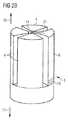
図1はニードルユニット2を含む薬物送達デバイス1を示す。ニードルアセンブリ5、16は、針5、及び針5の近位端に位置する針取付具16を含み、針5は針取付具16に固定されている。針保持体3は、針保持体アーム4及び停止部材6を含む。薬物送達デバイス1は、更に、ハウジング7、プランジャ8及びプランジャシール9を含む。プランジャシール9は、係合手段10を含む。デバイス1は、更にその上、ニードルシール11、後退手段12、プランジャシール9の係合手段10と係合するよう構成されている係合手段13、並びに排出部材15を含む。 FIG. 1 shows a drug delivery device 1 including a
薬物送達デバイス1は、方向矢印17(遠位)及び18(近位)でそれぞれ示す遠位端及び近位端を有する。遠位端は、薬物送達デバイス1の投与端に最も近い薬物送達デバイス1のその端部を参照する。近位端は投与端に対して反対側の薬物送達デバイス1のその端部である。 The drug delivery device 1 has a distal end and a proximal end indicated by directional arrows 17 (distal) and 18 (proximal), respectively. The distal end refers to that end of the drug delivery device 1 that is closest to the administration end of the drug delivery device 1. The proximal end is that end of the drug delivery device 1 opposite the administration end.
薬物送達デバイス1は、使い捨ての事前充填された安全注射器として設計されている。薬物送達デバイス1は、薬物の固定用量又は変更可能な(好ましくは、使用者が設定可能な)用量を投与することを意図し得る。 The drug delivery device 1 is designed as a disposable pre-filled safety syringe. The drug delivery device 1 may be intended to administer a fixed dose or a variable (preferably user configurable) dose of the drug.
薬物送達デバイス1は、ハウジング7を含む。薬物送達デバイス1が図1で示すような注射器である場合、ハウジング7は、バレル状に形成される。薬物送達デバイス1がペン型注射デバイス(図示されていないが)である場合、ハウジング7は、更なるエレメント、例えば、薬剤又は薬物容器、例えば、薬物の用量が貯蔵されるカートリッジを含む保持部材(図1では示されていないが)を含んでもよい。 The drug delivery device 1 includes a
バレルはガラス又はプラスチックから作ることができる。プランジャ8及びプランジャシール9は、実質的に縦軸に沿ってバレル内に移動することができる。 The barrel can be made from glass or plastic. The
針保持体3は、例えば、機械的摩擦によって、又は係合クリップで、ハウジング7に対して固定される。針保持体3は、また、ハウジング7に接着されてもよい。針保持体3は、薬物の用量送達の前及び送達時に針保持体3に対して移動に抗して針取付具16を固定することにより、ニードルアセンブリ5、16を固定する。針保持体3は、2つ又はそれ以上の針保持体アーム4を有する。 The
針5の近位部分は、針取付具16で支持され、それは摩擦を増加させ得て、そして、ニードルアセンブリ5、16を、後程説明する通り、薬物送達デバイス1内に後退させるために、ニードルアセンブリ5、16とプランジャシール9の係合を容易にする。ニードルアセンブリ5、16は、好ましくは、機械的摩擦、又は適切な機械的位置機能により針保持体3内に固定される。それにより針保持体アーム4は、針5を支持する針取付具16を経由して、ニードルアセンブリ5、16と係合する。針保持体アーム4は、また、係合手段、例えば、針取付具16と係合するためのニブを含んでもよい。針保持体アーム4は、可撓性材料で作られてもよい。 The proximal portion of the
ニードルアセンブリ5、16が針保持体3に固定されるとき、それは出発位置に位置する。薬物の用量が送達された後、ニードルアセンブリ5、16が完全に薬物送達デバイス1内に後退するとき、それは終了位置に移動した。 When the
ニードルシール11は、ニードルユニット2の近位端に置かれる。ハウジング7、ニードルシール11、及びプランジャシール9は、薬物用の流体気密容器を形成する。ニードルシール11は弾性材料、例えば、ゴムなどのエラストマーで作られてもよく、そして、ハウジング7の内部表面と針保持体3の間での流体シール、従って、ハウジング7の遠位開口部を提供し、それは、薬物が針5の内部孔を経由しないならば、ハウジング7とニードルアセンブリ5、16間を移動することができなくなることを意味する。 The
ニードルシール11は、ハウジング7に対して移動に抗して、解除可能なように固定され、そして、薬物の用量が送達された後、ハウジング7に対して遠位方向に移動するように意図されている。ニードルシール11は、機械的摩擦により、係合クリップにより、又はフランジにより、ハウジング7と解除可能なように係合し得る。 The
プランジャシール9は、好ましくは、エラストマー例えば、ゴムなどの弾性材料で作られ、ハウジング7の内部表面とプランジャ8の間での流体気密シール、従って、ハウジング7の遠位開口部を提供し、それは、薬物がハウジング7とプランジャ8の間を移動することができなくなることを意味する。プランジャシール9は、プランジャ8と一体的に形成し得る。しかし、プランジャシール9及びプランジャ8は、また、別々に形成され、即ち、プランジャシール9はプランジャ8に接続し得る。 The plunger seal 9 is preferably made of an elastomeric material such as an elastomer, for example rubber, and provides a fluid tight seal between the inner surface of the
ハウジング7、プランジャシール9及びニードルシール11は、流体気密薬剤容器を形成する。 The
この実施態様において、停止部材6は、図1で示される通り、針保持体3の一部である。それにより、停止部材6は、また、針保持体3を越えて半径方向の外側に広がる。 In this embodiment, the
停止部材は、好ましくは、可撓性又は付勢部材を含む(図2A及び2B参照)。好ましくは、可撓性又は付勢部材はスプリングアームであり、それは、ニードルアセンブリ5、16が出発位置にあるとき、事前に応力を受け、そして、ニードルアセンブリ5、16が薬物送達デバイス内に後退するとき、緩和される。可撓性又は付勢部材は、また、可撓性クリップ又はクランプであってもよく、それは、ニードルアセンブリ5、16が出発位置にあるとき、ゆがむか、又は湾曲する。 ニードルアセンブリ5、16が後退するとき、クリップ又はクランプは緩和する。 The stop member preferably includes a flexible or biasing member (see FIGS. 2A and 2B). Preferably, the flexible or biasing member is a spring arm that is pre-stressed when the
薬物の用量を送達するために、使用者は、プランジャ8を押し、それに応えて、プランジャ8は、ハウジング7に対して遠位方向に移動する。プランジャシール9は、また、ハウジング7に対して遠位的に、ニードルアセンブリ5、16及び針保持体3方向に押される。これは、薬剤又は医薬品容器、例えば、カートリッジから医薬品を押し出し、そして、薬物送達デバイス1の内容物を完全に投与した後、用量投与の終了時点で、プランジャシール9の遠位端はニードルシール11の近位端に隣接する。使用者はプランジャ8を押し続け、その結果、プランジャシール9、ニードルシール11を押し、そして、結果として、排出部材15をハウジング7に対して遠位方向に、ニードルアセンブリ5、16、及び針保持体3に向かって押す。 In order to deliver the dose of drug, the user pushes the
排出部材15は針保持体3の方向に向かって移動可能なように配置され、そして、接触及びその後の相互作用で、一実施態様においては、ニードルアセンブリ5、16に対して半径方向の外側に針保持体アーム4を移動する。その結果、ニードルアセンブリ5、16は、針保持体3、即ち、針保持体アーム4から固定を解除され、そして次の段階で、ニードルアセンブリ5、16は薬物送達デバイス1内に後退することができる。 The
一実施態様において、排出部材15は、針保持体アーム4並びに停止部材6を移動させ、ニードルアセンブリ5、16を針保持体3からロック解除する。別の実施態様において、事前に説明した通り、排出部材15は、針保持体アーム4のみを移動させ、そして、ニードルアセンブリ5、16は、一旦針保持体アーム4からロック解除され後退させられると、ハウジング7に対して近位方向に停止部材6に沿って摺動し得る。 In one embodiment, the
ニードルアセンブリ5、16を薬物送達デバイス1内に後退させるために、プランジャシール9は、ニードルアセンブリ5、16の嵌め合い係合手段13、即ち、針取付具16の近位端と係合するのに適した係合手段10を含む。それにより、係合手段10は、つまみ(lug)を含んでもよく、そして、嵌め合い係合手段13はノッチをふくんでもよく、逆もまた同様である。 In order to retract the
この実施態様において、係合手段10はノッチを含む。針取付具16の近位端が、もはや、ニードルシール11により覆われないとき、即ち、ニードルシール11がプランジャ9により遠位方向に押されるとき、針取付具16の近位端が機械的摩擦によりノッチと係合するために、ノッチはニードルアセンブリ5、16の嵌め合い係合手段13にぴったりと合う。 In this embodiment, the engagement means 10 includes a notch. When the proximal end of the
ニードルアセンブリ5、16が出発位置に位置するとき、それは、半径方向に外側に向く力を停止部材に与える。それ故、停止部材6の付勢又は可撓性部品は、事前に応力を受けた状態であり、そして、停止部材6は、ニードルアセンブリ5、16に対して半径方向の外側位置に維持される。 When the
組立てのため、例えば、薬物送達デバイス1を製造中に、ニードルアセンブリ5、16は、開口部を通して出発位置へ、ハウジング7に対して軸方向で遠位方向に移動できる。開口部14は、図2B〜5Bにおいてはっきりと示されている。開口部14は、針保持体3内で軸孔として形成し得て、そして、ニードルアセンブリ5、16を、例えば、出発位置から終了位置まで導くように設計されている。一実施態様において、初期には、組立中、ニードルアセンブリ5、16を、物送達デバイス1と係合しながら、停止部材6は、針保持体3に対して遠位方向に、ニードルアセンブリ5、16の出発位置へニードルアセンブリ5、16を移動することを可能とする。この実施態様において、ニードルアセンブリ5、16は、デバイス1の組立中、薬物送達デバイス1内に挿入され、デバイス1に対して遠位方向に動かされ、そして最終的に針保持体3内に、即ち針保持体アーム4の間に固定される。それにより、ニードルアセンブリ5、16の出発位置への遠位移動は、薬物送達デバイス1の組立中、一度のみ許される。 For assembly, for example during manufacture of the drug delivery device 1, the
用量が送達されたとき、ニードルアセンブリ5、16は、ハウジング7内に後退する。ニードルアセンブリ5、16の後退は、後程、より詳細に説明する。ニードルアセンブリ5、16が後退するとき、ニードルアセンブリ5、16が、もはや、ニードルアセンブリ5、16に対して、半径方向の外側位置に停止部材6を維持できなくなるので、停止部材6は針保持体3の開口部14をブロックする位置に緩和する。それ故、停止部材6は、(後退した)ニードルアセンブリ5、16に対して半径方向の内側に移動し、そして開口部14をブロックする。結果として、ニードルアセンブリ5、16を、開口部14を通じて遠位方向に移動させるその後の如何なる試みも、停止部材6によって制限され、それ故、後退したニードルアセンブリ5、16の再露出を阻止する。 When the dose is delivered, the
ニードルアセンブリ5、16を後退させるために、薬物送達デバイス1は、スプリング又はクリップを含んでもよい後退手段12を含む。ニードルアセンブリ5、16を針保持体3、即ち、針保持体アーム4からロック解除した後、後退手段12は、プランジャ8、プランジャシール9、及びプランジャシール9と係合するニードルアセンブリ5、16を、ハウジング7内に近位的に自動的に引っ張り得る。 In order to retract the
この目的のため、初期に圧縮した後退手段12は、プランジャ8がハウジング7に対して近位方向に移動するように、圧力を減らさなければならない。プランジャ8の係合アームがハウジング7の近位端に到達するとき、近位移動は、後退手段12、例えば、スプリングの圧力低下により達成し得る。圧力低下のため、プランジャ8は、ハウジング7に対して近位方向に動かされ、それにより、プランジャシール9及びそれに近位的に連結したニードルアセンブリ5、16を後退させる。従って、薬物送達デバイス1の再使用が阻止され、そして、デバイス1の安全な廃棄が可能となる。後退手段12の一実施態様は、例えば、特許文献1に記載されている。 For this purpose, the initially compressed retracting means 12 must reduce the pressure so that the
替わりの実施態様において、使用者は、ニードルアセンブリ5、16を、薬物を投与するためにプランジャ8を遠位的に押した後、プランジャ8を近位的に引くことにより手動で後退させる。 In an alternative embodiment, the user manually retracts the
図2Aは、図1のニードルユニットの透視図を概略的に示す。同じ参照番号が、図1の説明に対するものと同様に図2Aの説明に対して適用される。 FIG. 2A schematically shows a perspective view of the needle unit of FIG. The same reference numbers apply to the description of FIG. 2A as for the description of FIG.
図2Aは3つの針保持体アーム4を備えた針保持体3を示す。ニードルアセンブリ5、16は、針保持体3のアーム4内に、好ましくは、機械的摩擦により固定される。しかし、それは、また、針保持体アーム4の間で、つまみ、又はニードルアセンブリ5、16の針取付具16(図2Aでは図示されていないが)と係合する突起によって固定することができる。ニードルアセンブリ5、16は、出発位置に位置する。針保持体3は停止部材6を含む。停止部材6は付勢部材19(図2Aではドットで示される)を含む。停止部材6は図2Aで示す通り、角のある形状を有してもよい。 FIG. 2A shows a
ニードルアセンブリ5、16は、半径方向の力を停止部材6に与える。力は矢印20で示される。従って、停止部材6、特に、停止部材6の付勢部材19は、停止部材6がニードルアセンブリ5、16に対して半径方向の外側の位置に保持されるように、一旦ニードルアセンブリ5、16が針保持体3からロック解除されると、ニードルアセンブリ5、16は、ハウジング7に対して(図2Aにおいてニードルアセンブリ5、16により占有されている開口部14を通じて)軸方向に移動できるように、事前に応力を受ける。これにより、次の段階におけるニードルアセンブリ5、16の薬物送達デバイス1内にの後退が可能となる。 The
既に説明した通り、停止部材6は、それがニードルアセンブリ5、16により、半径方向の外側に押すことができるように、付勢部材19、例えば、スプリング又はクリップを含み得る。停止部材6の一実施態様は、停止部材が開口部14をブロックするように構成されたヒンジを含む。このヒンジは、停止部材6と一体的に形成することができる。一実施態様において、停止部材6は、停止部材6が開口部14をブロックするように構成された可撓性材料で作られている。停止部材6は、ニードルアセンブリ5、16により押されるとき、半径方向の外側に押される。 As already described, the
一実施態様において、停止部材6は、図2Aで示された通り、針保持体3の一部であってもよい。しかし、停止部材6は、また、針保持体3に接続できる。 In one embodiment, the
図2Bは、ニードルアセンブリが後退されている、図2Aのニードルユニットを概略的に示す。従って、ニードルアセンブリは図2Bにおいては示されていない。図2Bは針保持体3の開口部14を示す。 FIG. 2B schematically illustrates the needle unit of FIG. 2A with the needle assembly retracted. Accordingly, the needle assembly is not shown in FIG. 2B. FIG. 2B shows the
図2Bにおいて、ニードルアセンブリ5、16は、薬物送達デバイス1(図示されていないが)内に後退する。例えば、ニードルアセンブリ5.16は、終了位置まで後退する。一旦ニードルアセンブリ5、16が後退すると、それは、もはや、停止部材6が矢印21で示されるニードルアセンブリ5、16に対して半径方向の内側に移動できるように、停止部材6、特に、停止部材6の付勢部材19に圧力を低下させる力を停止部材6に与えることができない。それ故、停止部材6は開口部14をブロックし、そして、その結果、ハウジング7に対して遠位方向における開口部14を通したニードルアセンブリ5、16のその後の移動を阻止する。 In FIG. 2B, the
図3Aは、出発位置においてニードルアセンブリを備えた、図1〜2Bのニードルユニットの近位端図を概略的に示す。同じ参照番号は、図3Aの説明に対して、図1、2A及び2Bの説明と同様に適用される。 FIG. 3A schematically shows a proximal end view of the needle unit of FIGS. 1-2B with the needle assembly in a starting position. The same reference numbers apply to the description of FIG. 3A as in the description of FIGS. 1, 2A and 2B.
図3Aは、3つの針保持体アーム4を備えた針保持体3、及びニードルアセンブリ5、16を含むニードルユニット2の近位端の平面図を示す。ニードルアセンブリ5、16は、針取付具16により覆われる針5を含む。針保持体3は、停止部材6を含む。更に、図3Aは、ニードルアセンブリ5、16により充填されている針保持体3の開口部14を示す。図3Aは、また、薬物送達デバイス1(図3Aにおいては外周円で提示されている)のハウジング7を示す。 FIG. 3A shows a top view of the proximal end of the
針保持体3は、種々の方法で固定できよう。針保持体3は、ハウジング7に対して、例えば、機械的摩擦によって固定される。 The
図3Aは、薬物の用量を投与する前の出発位置におけるニードルアセンブリ5、16を示す。ニードルアセンブリ5、16は、針保持体アーム4と、針保持体3に対してニードルアセンブリ5、16の移動を阻止する停止部材6の間で固定されている。ニードルアセンブリ5、16は、種々の方法で針保持体内に保持できよう。ニードルアセンブリ5、16は、機械的摩擦によって針保持体アーム4内に保持し得る。ニードルアセンブリ5、16は、針保持体3の開口部14に位置する。 FIG. 3A shows the
停止部材6は、好ましくは、付勢又は可撓性部品(図2A及び2B参照)を含み、例えば、停止部材は、既に以前に説明した通り、スプリングアーム又はクリップを含む。好ましくは、停止部材6は針保持体3の一部であってもよく、又は針保持体3と接続してもよい。 The
ニードルアセンブリ5、16は、停止部材6に力を与える。それにより、停止部材6の付勢又は可撓性部品は、事前に応力を受けるようになり、そして、停止部材6は、半径方向の外側に押され、ハウジング7に対してニードルアセンブリ5、16の軸方向の移動を可能とし、その結果、開口部14が停止材6から自由に維持できるので、一旦ニードルアセンブリ5、16が、針保持体3から固定解除されると、薬物送達デバイス1内にのニードルアセンブリ5、16の後退も可能となる。 The
図3Bは図3Aのニードルユニットの側面図を概略的に示す。 FIG. 3B schematically shows a side view of the needle unit of FIG. 3A.
図3Bは左側面から見られる図3Aのニードルユニット2の側面図を表す。それにより、図3Bは、再度出発位置にあるニードルアセンブリ5、16を係合する針保持体アーム4を備えた針保持体3を示す。ニードルアセンブリ5、16は、針保持体3の開口部14を完全にブロックする。従って、停止部材6(図示されていないが)は、ニードルアセンブリ5、16により、半径方向の外側に押される。 FIG. 3B represents a side view of the
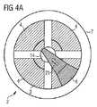
図4Aは、終了位置におけるニードルアセンブリを備えた図1〜3Aのニードルユニットの近位端図を概略的に示す。図3Aと対比して、ニードルアセンブリ5、16は、図4Aにおいては後退し、その結果、図4Aはニードルアセンブリ5、16を示さない。 FIG. 4A schematically shows a proximal end view of the needle unit of FIGS. 1-3A with the needle assembly in an end position. In contrast to FIG. 3A, the
図4Aは3つの針保持体アーム4を備えた針保持体3を示す。針保持体3は停止部材6を含む。図4Aは、また、針保持体3の開口部14を示し、そして、薬物送達デバイスのハウジング7(図4Aにおける外周円)を示す。 FIG. 4A shows a
ニードルアセンブリ5、16が、後退位置、例えば、終了位置にあるので、図4Aは、ニードルアセンブリ5、16を示さない。ニードルアセンブリ5、16を後退させるとき、ニードルアセンブリ5、16は、針保持体3の開口部14から解放される(set free)。結果として、ニードルアセンブリ5、16は、もはや、停止部材6に力を与えることができない。それ故、停止部材6の可撓性又は付勢部材19(図2A及び2B参照)は、圧力を低下し、そして、停止部材6は、実線矢印21で示す通り、針保持体3の開口部14をロックする位置に対して、半径方向の内側に緩和する。ニードルアセンブリ5、16は、その出発位置に配置されるために、デバイス1に対して遠位方向に、針保持体3の開口部14を通じて移動しなければならないので、ニードルアセンブリ5、16の再露出は結果として阻止される。 FIG. 4A does not show the
図4Bは、図4Aのニードルユニットの側面図を概略的に示す。 FIG. 4B schematically shows a side view of the needle unit of FIG. 4A.
図4Bは、左側から見た図4Aのニードルユニット2の側面図を表す。図4Bは針保持体アーム4を備えた針保持体3を示す。また、図4Aは、実線矢印21で示すように、(後退した)ニードルアセンブリ5、16に対して半径方向の内側に移動した停止部材6を示す。(後退した)ニードルアセンブリ5、16に対して半径方向の内側への移動の故に、停止部材6は、針保持体3の開口部14をブロックし、そして、後退したニードルアセンブリ5、16の再露出を阻止する。 4B represents a side view of the
図5A及び5Bで示された更なる実施態様において、針保持体3は遠位方向に向く追加のアーム有し、それはニードルアセンブリ5、16の存在によって半径方向の外側に強制される。ニードルアセンブリ5、16の除去に際し、即ち、デバイス1のハウジング7内にの近位後退に際し、付勢を受けたアームは、半径方向の内側に緩和して、針保持体の開口部14をブロックし、そして、その後のハウジング7に対して再露出する位置へのニードルアセンブリ5、16の通過を阻止する。遠位的に面する針保持体アーム4の最遠位端での逆止め機構は、更に、その後のニードルアセンブリ5、16の遠位走行をブロックすることを支援する。 In a further embodiment shown in FIGS. 5A and 5B, the
図5Aはニードルユニットの更なる実施態様を概略的に示す。 FIG. 5A schematically shows a further embodiment of the needle unit.
図5Aは、この実施態様において、針保持体3の近位端に位置する4つの針保持体アーム4(明確にするため、2つの針保持体4のみが図5Aで示されている)を含む針保持体3を示す。ニードルアセンブリ5、16は、種々の方法で、例えば、機械的位置づけ又はスナップフィットによって固定し得るが、ニードルアセンブリ5、16、即ち、針取付具16に支持されている針5は、針保持体アーム4の間で、好ましくは、機械的摩擦によって固定される。それ故、ニードルアセンブリ5、16は、出発位置にある。ニードルアセンブリ5、16は、針保持体3の開口部を占有する。 FIG. 5A shows that in this embodiment four needle holder arms 4 (only two
針保持体3は停止部材6を含む。停止部材6は、この実施態様において、4つのアームを含むが、理由を明確にするため、停止部材6の2つのアームのみが図5Aにおいて示されている。この実施態様において、停止部材6は、針保持体3の遠位端で配置されている。停止部材6は、遠位端で、連結手段22を、この実施態様においては、爪を含み、それは、ニードルアセンブリ5、16に対して、半径方向の内側に配置され、そして、ニードルアセンブリ5、16が薬物送達デバイス1(図5Aに示されていないが)内に後退した後、互いに係合するよう構成されている。針保持体アーム4の最遠位端でのこれらの逆止め機構、即ち、連結手段22は、更に、ニードルアセンブリ5、16のその後の遠位走行のロックを支援する(図5B参照)。 The
図1〜4Bに関連して既に説明した通り、停止部材6は、好ましくは、可撓性、又は付勢部材、例えば、スプリングアーム又はクリップを含む(図2A及び2B参照)。図5Aにおいて、ニードルアセンブリ5、16は、出発位置において、停止部材6、特に、停止部材6の付勢部材を、ニードルアセンブリ5、16に対して半径方向の外側に押している。 As already described in connection with FIGS. 1-4B, the
図5Aは、また、排出部材15を示し、それは、針保持体3の近位端で配置され、そして、以前に説明した通り、薬物送達デバイスの内容物が送達された後、針保持体3、即ち、針保持体アーム4から後退可能なニードルアセンブリ5、16を解除する働きをする。 FIG. 5A also shows a draining
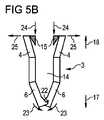
図5Bは、ニードルアセンブリが後退されている図5Aのニードルユニットを示す。 FIG. 5B shows the needle unit of FIG. 5A with the needle assembly retracted.
用量が完全送達された後、ニードルシール11(図5Aでは示されていないが)は、排出部材15に押し付け、それは、その後、矢印24で示す通り、近位方向で、針保持体3に向かって移動し、針保持体アーム4を半径方向の外側に(矢印25)移動させる。その結果、ニードルアセンブリ5、16を、針保持体3、即ち、針保持アーム4から固定を解除し、そして、図1の説明との関連で説明した通り、薬物送達デバイス内に後退することができる。 After the dose has been fully delivered, the needle seal 11 (not shown in FIG. 5A) presses against the
図5Bは、ニードルアセンブリ5、16がデバイス内に後退した後のニードルユニット2を示し、従って、ニードルアセンブリ5、16は、図5Bでは示されない。ニードルアセンブリ5、16が後退するにつれて、それは、もはや、停止部材6に力を与えることができない。結果として、停止部材6、特に、停止部材6の付勢部材は圧力を下げ、(後退した)ニードルアセンブリ5、16に対して矢印23で示される通り半径方向の内側に移動する。それにより、停止部材6の連結手段22は、互いに係合し、(後退した)ニードルアセンブリ5、16に対して、半径方向の外側への、停止部材6の更なる移動を阻止する。それ故、停止部材6は効率的に開口部14をブロックし、ニードルアセンブリ5、16の遠位方向における開口部14を経由した移動を阻止する。 FIG. 5B shows the
他の実行態様(implementation)は本請求項の範囲内にある。異なる実行態様の要素は組み合されて本明細書に特別に述べられていない実行態様を形成し得る。 Other implementations are within the scope of the claims. The elements of the different implementations may be combined to form an implementation that is not specifically described herein.
参照数字
1:薬物送達デバイス;
2:ニードルユニット;
3:針保持体;
4:針保持体アーム;
5:針;
6:停止部材;
7:ハウジング;
8:プランジャ;
9:プランジャシール;
10:係合手段;
11:ニードルシール;
12:後退手段;
13:係合手段;
14:開口部;
15:排出部材;
16:針取付具;
17:遠位端;
18:近位端;
19:付勢部材;
20:矢印;
21:矢印;
22:連結手段;
23:矢印;
24:矢印;
25:矢印;Reference number 1: drug delivery device;
2: Needle unit;
3: Needle holder;
4: Needle holder arm;
5: Needle;
6: Stop member;
7: Housing;
8: Plunger;
9: Plunger seal;
10: engagement means;
11: Needle seal;
12: Retreat means;
13: engagement means;
14: Opening;
15: discharge member;
16: Needle fitting;
17: distal end;
18: proximal end;
19: biasing member;
20: arrow;
21: Arrow;
22: connection means;
23: arrow;
24: Arrow;
25: Arrow;
Claims (18)
Translated fromJapanese薬物送達デバイス(1)内に出発位置から終了位置まで後退可能である針(5)、及び停止部材(6)を有する針保持体(3)を含み、ここで、その針(5)は針取付具(16)を有する針として形成されたニードルアセンブリ(5、16)の一部である、その針保持体(3)は、薬物の用量を送達する前又は送達するとき、針保持体(3)に対して移動に抗して針取付具(16)を固定することによりニードルアセンブリ(5、16)を固定する、その針保持体(3)は針保持体アーム((4)を含み、針保持体アーム(4)は針を支持する針取付具(16)を介してニードルアセンブリ(5,16)と係合する、停止部材(6)は、針(5)が薬物送達デバイス(1)内に後退したとき、針(5)の再露出を阻止するように構成されている、上記ニードルユニット(2)。A needle unit (2) for a drug delivery device (1) comprising:
The drug delivery device (1) includes a needle (5) that is retractable from a starting position to an ending position and a needle holder (3) having a stop member (6), wherethe needle (5) is a needle The needle holder (3), which is part of the needle assembly (5, 16) formed as a needle with a fitting (16), is provided with a needle holder ( 3) Fix the needle assembly (5, 16) by fixing the needle fixture (16) against movement relative to the movement, the needle holder (3) includes a needle holder arm ((4)) The needle holder arm (4) engages the needle assembly (5, 16) via a needle fixture (16) that supports the needle, the stop member (6), the needle (5) is connected to the drug delivery device ( 1) configured to prevent re-exposure of needle (5) when retracted into , The needle unit (2).
薬物送達デバイス(1)。17. A needle assembly (5, comprisinga needle unit according to any one of claims 1 to 16 and further comprising a housing (7), a needle holder (3), a needle retraction means (12) and a needle (5). 16)a including drug delivery device, wherein the needle assembly (5,16) is in a housing (7), from a starting position in which the needle of the needle assembly (5,16) (5) is exposed, The needle (5) can be retracted to an end position where the needle (5) is not exposed, and the needle holder (3) is then moved from the initiallocked state by the needle retracting means (12). The opening (14) from which the needle (5) protrudes is at least partially closed when the needle (5) is retracted, and is configured to release into an unlockedstate so that it can be retracted. , Needle (5 Of comprising a stop member for preventing the next re-exposure (6);
Drug delivery device (1).
Applications Claiming Priority (3)
| Application Number | Priority Date | Filing Date | Title |
|---|---|---|---|
| EP09003178.2 | 2009-03-05 | ||
| EP09003178 | 2009-03-05 | ||
| PCT/EP2010/052788WO2010100243A1 (en) | 2009-03-05 | 2010-03-04 | Needle unit |
Publications (2)
| Publication Number | Publication Date |
|---|---|
| JP2012519511A JP2012519511A (en) | 2012-08-30 |
| JP5570533B2true JP5570533B2 (en) | 2014-08-13 |
Family
ID=40902035
Family Applications (1)
| Application Number | Title | Priority Date | Filing Date |
|---|---|---|---|
| JP2011552455AExpired - Fee RelatedJP5570533B2 (en) | 2009-03-05 | 2010-03-04 | Needle unit |
Country Status (7)
| Country | Link |
|---|---|
| US (1) | US20120116306A1 (en) |
| EP (1) | EP2403568B1 (en) |
| JP (1) | JP5570533B2 (en) |
| AU (1) | AU2010220257B2 (en) |
| CA (1) | CA2753982A1 (en) |
| DK (1) | DK2403568T3 (en) |
| WO (1) | WO2010100243A1 (en) |
Families Citing this family (29)
| Publication number | Priority date | Publication date | Assignee | Title |
|---|---|---|---|---|
| WO2003068290A2 (en) | 2002-02-11 | 2003-08-21 | Antares Pharma, Inc. | Intradermal injector |
| HUE042286T2 (en) | 2005-01-24 | 2019-06-28 | Antares Pharma Inc | Needle-filled pre-filled syringe |
| US20070202186A1 (en) | 2006-02-22 | 2007-08-30 | Iscience Interventional Corporation | Apparatus and formulations for suprachoroidal drug delivery |
| US8197435B2 (en) | 2006-05-02 | 2012-06-12 | Emory University | Methods and devices for drug delivery to ocular tissue using microneedle |
| WO2007131025A1 (en) | 2006-05-03 | 2007-11-15 | Antares Pharma, Inc. | Injector with adjustable dosing |
| WO2007131013A1 (en) | 2006-05-03 | 2007-11-15 | Antares Pharma, Inc. | Two-stage reconstituting injector |
| EP3636301A1 (en) | 2008-03-10 | 2020-04-15 | Antares Pharma, Inc. | Injector safety device |
| US8376993B2 (en) | 2008-08-05 | 2013-02-19 | Antares Pharma, Inc. | Multiple dosage injector |
| JP5996544B2 (en) | 2010-10-15 | 2016-09-21 | クリアサイド・バイオメディカル・インコーポレーテッドClearside Biomedical Incorporated | Eye access device |
| US8496619B2 (en) | 2011-07-15 | 2013-07-30 | Antares Pharma, Inc. | Injection device with cammed ram assembly |
| US9220660B2 (en) | 2011-07-15 | 2015-12-29 | Antares Pharma, Inc. | Liquid-transfer adapter beveled spike |
| US9486583B2 (en) | 2012-03-06 | 2016-11-08 | Antares Pharma, Inc. | Prefilled syringe with breakaway force feature |
| EP4186545A1 (en) | 2012-04-06 | 2023-05-31 | Antares Pharma, Inc. | Needle assisted jet injection administration of testosterone compositions |
| US9364610B2 (en) | 2012-05-07 | 2016-06-14 | Antares Pharma, Inc. | Injection device with cammed ram assembly |
| KR20210133321A (en) | 2012-11-08 | 2021-11-05 | 클리어사이드 바이오메디컬, 인코포레이드 | Methods and devices for the treatment of ocular disease in human subjects |
| FI3659647T3 (en) | 2013-02-11 | 2024-03-28 | Antares Pharma Inc | NEEDLE-ASSISTED SPRAY INJECTOR WITH REDUCED TRIGGER FORCE |
| CA2905031C (en) | 2013-03-11 | 2018-01-23 | Hans PFLAUMER | Dosage injector with pinion system |
| CA2911290C (en) | 2013-05-03 | 2021-07-27 | Clearside Biomedical, Inc. | Apparatus and methods for ocular injection |
| EP3003454B1 (en) | 2013-06-03 | 2020-01-08 | Clearside Biomedical, Inc. | Apparatus for drug delivery using multiple reservoirs |
| US9861763B2 (en)* | 2013-07-01 | 2018-01-09 | Credence Medsystems, Inc. | Safety syringe |
| US10300217B2 (en) | 2013-11-15 | 2019-05-28 | Credence Medsystems, Inc. | System and method for drug delivery with a safety syringe |
| PL3134152T3 (en) | 2014-04-24 | 2021-12-20 | Credence Medsystems Inc. | System for safety syringe |
| RU2710491C2 (en) | 2014-06-20 | 2019-12-26 | Клиасайд Байомедикал, Инк. | Device for drug injection into ocular tissue and method for drug injection into ocular tissue |
| USD750223S1 (en) | 2014-10-14 | 2016-02-23 | Clearside Biomedical, Inc. | Medical injector for ocular injection |
| JP6099612B2 (en)* | 2014-10-22 | 2017-03-22 | 日出夫 文山 | Puncture needle unit, puncture needle device and safety tube for them |
| EP3413851B1 (en) | 2016-02-10 | 2023-09-27 | Clearside Biomedical, Inc. | Packaging |
| WO2017192565A1 (en) | 2016-05-02 | 2017-11-09 | Clearside Biomedical, Inc. | Systems and methods for ocular drug delivery |
| US10973681B2 (en) | 2016-08-12 | 2021-04-13 | Clearside Biomedical, Inc. | Devices and methods for adjusting the insertion depth of a needle for medicament delivery |
| US12090294B2 (en) | 2017-05-02 | 2024-09-17 | Georgia Tech Research Corporation | Targeted drug delivery methods using a microneedle |
Family Cites Families (13)
| Publication number | Priority date | Publication date | Assignee | Title |
|---|---|---|---|---|
| US4935014A (en)* | 1988-06-24 | 1990-06-19 | Habley Medical Technology Corporation | Combination retractable needle cannual and cannual lock for a medication carpule |
| US5578015A (en)* | 1989-09-18 | 1996-11-26 | Robb Pascal Patent Limited | Safety syringe incorporating automatic needle holder release |
| US5344408A (en)* | 1993-08-06 | 1994-09-06 | Becton, Dickinson And Company | Break-away safety shield for needle cannula |
| US5836917A (en)* | 1995-01-10 | 1998-11-17 | Specialized Health Products, Inc. | Self retracting medical needle apparatus and methods |
| US5582597A (en)* | 1995-07-11 | 1996-12-10 | Becton Dickinson And Company | Rotary ram collet lock needle point guard |
| US6569115B1 (en)* | 1997-08-28 | 2003-05-27 | Mdc Investment Holdings, Inc. | Pre-filled retractable needle injection device |
| US5971964A (en)* | 1999-01-14 | 1999-10-26 | Donaldson; Neil | Retractable syringe |
| US20030105430A1 (en)* | 2001-11-30 | 2003-06-05 | Elan Pharma International Limited Wil House | Automatic injector |
| US20040186426A1 (en)* | 2003-03-20 | 2004-09-23 | Allard Edward F. | Blood collecting syringe with retractable needle |
| CN100382856C (en)* | 2003-12-22 | 2008-04-23 | 王治明 | safety syringe |
| CA2604322C (en)* | 2005-04-15 | 2016-05-24 | Unitract Syringe Pty Ltd | Controlled retraction syringe and plunger therefor |
| JP4723419B2 (en)* | 2006-05-24 | 2011-07-13 | テルモ株式会社 | Indwelling needle assembly |
| WO2009148969A1 (en)* | 2008-06-02 | 2009-12-10 | Sta-Med, Llc | Needle cover assembly for a syringe |
- 2010
- 2010-03-04JPJP2011552455Apatent/JP5570533B2/ennot_activeExpired - Fee Related
- 2010-03-04AUAU2010220257Apatent/AU2010220257B2/ennot_activeCeased
- 2010-03-04USUS13/202,438patent/US20120116306A1/ennot_activeAbandoned
- 2010-03-04CACA2753982Apatent/CA2753982A1/ennot_activeAbandoned
- 2010-03-04DKDK10706266Tpatent/DK2403568T3/enactive
- 2010-03-04WOPCT/EP2010/052788patent/WO2010100243A1/enactiveApplication Filing
- 2010-03-04EPEP10706266.3Apatent/EP2403568B1/enactiveActive
Also Published As
| Publication number | Publication date |
|---|---|
| AU2010220257A1 (en) | 2011-09-22 |
| EP2403568B1 (en) | 2014-12-17 |
| US20120116306A1 (en) | 2012-05-10 |
| EP2403568A1 (en) | 2012-01-11 |
| AU2010220257B2 (en) | 2015-01-15 |
| JP2012519511A (en) | 2012-08-30 |
| CA2753982A1 (en) | 2010-09-10 |
| WO2010100243A1 (en) | 2010-09-10 |
| DK2403568T3 (en) | 2015-03-23 |
Similar Documents
| Publication | Publication Date | Title |
|---|---|---|
| JP5570533B2 (en) | Needle unit | |
| US11730888B2 (en) | Auto-injector | |
| JP5756469B2 (en) | Drug delivery device | |
| JP5791637B2 (en) | Finger protection for injection devices | |
| JP5797209B2 (en) | Automatic syringe | |
| TWI597084B (en) | Automatic syringe (5) | |
| JP5756468B2 (en) | Assembly for use in a drug delivery device | |
| JP5794992B2 (en) | Drug delivery device with clearance compensation means | |
| TW201302258A (en) | Auto-injector |
Legal Events
| Date | Code | Title | Description |
|---|---|---|---|
| A621 | Written request for application examination | Free format text:JAPANESE INTERMEDIATE CODE: A621 Effective date:20130221 | |
| A131 | Notification of reasons for refusal | Free format text:JAPANESE INTERMEDIATE CODE: A131 Effective date:20140128 | |
| A521 | Request for written amendment filed | Free format text:JAPANESE INTERMEDIATE CODE: A523 Effective date:20140428 | |
| TRDD | Decision of grant or rejection written | ||
| A01 | Written decision to grant a patent or to grant a registration (utility model) | Free format text:JAPANESE INTERMEDIATE CODE: A01 Effective date:20140527 | |
| A61 | First payment of annual fees (during grant procedure) | Free format text:JAPANESE INTERMEDIATE CODE: A61 Effective date:20140624 | |
| R150 | Certificate of patent or registration of utility model | Ref document number:5570533 Country of ref document:JP Free format text:JAPANESE INTERMEDIATE CODE: R150 | |
| LAPS | Cancellation because of no payment of annual fees |