JP5569297B2 - Waterproof connector - Google Patents
Waterproof connectorDownload PDFInfo
- Publication number
- JP5569297B2 JP5569297B2JP2010214310AJP2010214310AJP5569297B2JP 5569297 B2JP5569297 B2JP 5569297B2JP 2010214310 AJP2010214310 AJP 2010214310AJP 2010214310 AJP2010214310 AJP 2010214310AJP 5569297 B2JP5569297 B2JP 5569297B2
- Authority
- JP
- Japan
- Prior art keywords
- rubber plug
- housing
- positioning
- holder
- wire insertion
- Prior art date
- Legal status (The legal status is an assumption and is not a legal conclusion. Google has not performed a legal analysis and makes no representation as to the accuracy of the status listed.)
- Expired - Fee Related
Links
- 229920001971elastomerPolymers0.000claimsdescription142
- 238000003780insertionMethods0.000claimsdescription30
- 230000037431insertionEffects0.000claimsdescription30
- 230000002093peripheral effectEffects0.000claimsdescription24
- 239000002184metalSubstances0.000description3
- 210000000078clawAnatomy0.000description2
- 238000005520cutting processMethods0.000description2
- 230000013011matingEffects0.000description2
- 238000000034methodMethods0.000description2
- 238000000465mouldingMethods0.000description2
- 230000004308accommodationEffects0.000description1
- 238000013459approachMethods0.000description1
- 238000005452bendingMethods0.000description1
- 238000004519manufacturing processMethods0.000description1
- 239000000463materialSubstances0.000description1
- 238000004080punchingMethods0.000description1
- 229920005989resinPolymers0.000description1
- 239000011347resinSubstances0.000description1
- 230000000717retained effectEffects0.000description1
- 229920002379silicone rubberPolymers0.000description1
- 238000003860storageMethods0.000description1
- 229920003002synthetic resinPolymers0.000description1
- 239000000057synthetic resinSubstances0.000description1
Images


Classifications
- H—ELECTRICITY
- H01—ELECTRIC ELEMENTS
- H01R—ELECTRICALLY-CONDUCTIVE CONNECTIONS; STRUCTURAL ASSOCIATIONS OF A PLURALITY OF MUTUALLY-INSULATED ELECTRICAL CONNECTING ELEMENTS; COUPLING DEVICES; CURRENT COLLECTORS
- H01R13/00—Details of coupling devices of the kinds covered by groups H01R12/70 or H01R24/00 - H01R33/00
- H01R13/46—Bases; Cases
- H01R13/52—Dustproof, splashproof, drip-proof, waterproof, or flameproof cases
- H01R13/5205—Sealing means between cable and housing, e.g. grommet
- H01R13/5208—Sealing means between cable and housing, e.g. grommet having at least two cable receiving openings
- B—PERFORMING OPERATIONS; TRANSPORTING
- B29—WORKING OF PLASTICS; WORKING OF SUBSTANCES IN A PLASTIC STATE IN GENERAL
- B29C—SHAPING OR JOINING OF PLASTICS; SHAPING OF MATERIAL IN A PLASTIC STATE, NOT OTHERWISE PROVIDED FOR; AFTER-TREATMENT OF THE SHAPED PRODUCTS, e.g. REPAIRING
- B29C45/00—Injection moulding, i.e. forcing the required volume of moulding material through a nozzle into a closed mould; Apparatus therefor
- B29C45/17—Component parts, details or accessories; Auxiliary operations
- B29C45/26—Moulds
- B29C45/2628—Moulds with mould parts forming holes in or through the moulded article, e.g. for bearing cages
- B—PERFORMING OPERATIONS; TRANSPORTING
- B29—WORKING OF PLASTICS; WORKING OF SUBSTANCES IN A PLASTIC STATE IN GENERAL
- B29C—SHAPING OR JOINING OF PLASTICS; SHAPING OF MATERIAL IN A PLASTIC STATE, NOT OTHERWISE PROVIDED FOR; AFTER-TREATMENT OF THE SHAPED PRODUCTS, e.g. REPAIRING
- B29C45/00—Injection moulding, i.e. forcing the required volume of moulding material through a nozzle into a closed mould; Apparatus therefor
- B29C45/17—Component parts, details or accessories; Auxiliary operations
- B29C45/40—Removing or ejecting moulded articles
- B29C45/44—Removing or ejecting moulded articles for undercut articles
Landscapes
- Engineering & Computer Science (AREA)
- Manufacturing & Machinery (AREA)
- Mechanical Engineering (AREA)
- Connector Housings Or Holding Contact Members (AREA)
Description
Translated fromJapanese本発明は、防水コネクタに関する。The present invention also relatesto a waterproofconnector.
防水コネクタは、複数のキャビティを有するとともに、後面にゴム栓収容部が開口して形成されたハウジングと、ゴム栓収容部に収容され、各キャビティと連通する複数の電線挿通孔を有するゴム栓と、ハウジングに装着され、ゴム栓の抜け止めを行うホルダとを備えている(例えば、特許文献1を参照)。 The waterproof connector has a plurality of cavities, a housing formed by opening a rubber plug housing portion on the rear surface, a rubber plug having a plurality of wire insertion holes housed in the rubber plug housing portion and communicating with the cavities. And a holder that is attached to the housing and prevents the rubber stopper from coming off (see, for example, Patent Document 1).
ゴム栓は、所定の肉厚をもったマット状であって、前方及び後方から見ると四隅に丸みのついた矩形状をなしている。 The rubber plug has a mat shape with a predetermined thickness, and has a rectangular shape with rounded corners when viewed from the front and rear.
ところで、従来のゴム栓は、例えば、表裏反転の姿勢をとった状態で、ゴム栓収容部に収容されることがあった。しかし、ゴム栓の表裏面のそれぞれで構造の識別を行う必要がある場合に、ゴム栓がその表裏面を誤ってゴム栓収容部に収容されると、改めてゴム栓の収容作業をやり直さねばならず、作業負担が大きいという事情があった。 By the way, the conventional rubber stopper may be accommodated in the rubber stopper accommodating portion, for example, in a state where the front and back are reversed. However, when it is necessary to identify the structure on the front and back surfaces of the rubber plug, if the rubber plug is mistakenly stored in the rubber plug housing part, the rubber plug must be re-stored. However, there was a situation that the work burden was heavy.
本発明は上記のような事情に基づいて完成されたものであって、ゴム栓の装着が適正になされるようにすることを目的とする。 The present invention has been completed on the basis of the above-described circumstances, and an object thereof is to appropriately attach a rubber stopper.
上記の目的を達成するための手段として、請求項1の発明は、端子金具を収容可能なキャビティを有するとともに、後面にゴム栓収容部が開口して形成されたハウジングと、前記ゴム栓収容部に収容され、前記各キャビティと連通する電線挿通孔を有するゴム栓と、前記ハウジングに装着され、前記ゴム栓の抜け止めを行うホルダとを備えた防水コネクタであって、前記ゴム栓には、位置決め部が形成され、前記ゴム栓収容部又は前記ホルダには、前記ゴム栓が、前記ゴム栓収容部又は前記ホルダに対し、正規の姿勢をとる場合には前記位置決め部と嵌合して装着される一方、不正な姿勢をとる場合には前記位置決め部と干渉して前記ゴム栓の装着を不能とする位置決め受け部が形成され、前記ゴム栓の周縁部には、共に全周に沿った2条のリップが厚み方向に並んで形成され、前記位置決め部が、前記両リップの間の谷部においてその深さ方向に凹み形成される凹部を含み、前記凹部が、前記ゴム栓の成形時にこのゴム栓の平面方向に沿う方向へ進退可能なスライド型によって形成されているところに特徴を有する。As means for achieving the above-mentioned object, the invention of claim 1 includes a housing having a cavity capable of accommodating a terminal fitting and having a rubber plug accommodating portion opened on the rear surface, and the rubber plug accommodating portion. Is a waterproof connector provided with a rubber plug having a wire insertion hole that communicates with each of the cavities, and a holder that is attached to the housing and prevents the rubber plug from being detached. A positioning part is formed, and the rubber plug receiving part or the holder is fitted with the positioning part when the rubber plug takes a normal posture with respect to the rubber plug receiving part or the holder. On the other hand, if the posture is incorrect, a positioning receiving portion is formed which interferes with the positioning portion and makes it impossible to attach therubber plug. Both peripheral edges of the rubber plug are along the entire circumference.
請求項2の発明は、請求項1に記載のものにおいて、前記キャビティが、複数種の前記端子金具を収容可能な複数種によって構成され、かつ、前記ゴム栓収容部を後方から見た場合に、前記各キャビティが点対称の位置に配置されており、前記位置決め部が、前記ゴム栓の周縁部における点対称の位置において内方へ全肉厚範囲に亘って凹み形成され、前記位置決め受け部が、前記ゴム栓収容部の周壁内面又は前記ホルダの周壁内面における前記位置決め部と対応する点対称の位置に配置されているところに特徴を有する。 According to a second aspect of the present invention, the cavity according to the first aspect is configured by a plurality of types capable of accommodating a plurality of types of the terminal fittings, and the rubber plug housing portion is viewed from the rear. Each of the cavities is disposed at a point-symmetrical position, and the positioning portion is recessed inwardly over the entire thickness range at a point-symmetrical position at the peripheral edge of the rubber plug, and the positioning receiving portion However, it is characterized in that it is arranged at a point-symmetrical position corresponding to the positioning portion on the inner surface of the peripheral wall of the rubber stopper housing portion or the inner surface of the peripheral wall of the holder.
請求項3の発明は、請求項1又は2に記載のものにおいて、前記凹部が、複数の前記電線挿通孔のうち前記ゴム栓の周縁部寄りに配置された端部側の電線挿通孔を挟んだ一方の側に形成され、他方の側には、前記両リップの間の谷部においてその深さ方向に凹み形成された切除部が配置され、これにより、前記端部側の電線挿通孔の周りで前記ゴム栓の端部寄りのほぼ半周領域の径方向に関する寸法がほぼ等しくなっているところに特徴を有する。According to a third aspect of the present invention, in theone according to the first or second aspect, theconcave portion sandwiches the wire insertion hole on the end portion side disposed near the peripheral edge of the rubber plug among the plurality of the wire insertion holes. On the other side, the other side is provided with a cut portion that is recessed in the depth direction at the valley between the two lips, so that the wire insertion hole on the end side is arranged. It is characterized in that thedimensions in the radial direction of the substantially half-circumferential region around the end of the rubber plug are substantially equal around .
<請求項1の発明>
ゴム栓がゴム栓収容部又はホルダに対し正規の姿勢をとる場合には、位置決め受け部が位置決め部と嵌合してゴム栓の装着が許容される一方、ゴム栓が不正な姿勢をとる場合には、位置決め受け部が位置決め部と干渉してゴム栓の装着が不能とされるため、ゴム栓が不正な姿勢をとったままゴム栓収容部又はホルダに装着される事態が回避される。その結果、ゴム栓の装着が適正になされる。また、例えば、一対の金型でゴム栓の表裏面を成形する際、ゴム栓が可動型に付着した状態で型開きされることがある。しかし、本発明によれば、スライド型が引っ掛かりとなることにより、ゴム栓が可動型に付着して型開きされるのが防止される。しかも、スライド型によって位置決め部の凹部が形成されるため、金型の構成が複雑になるのが回避される。<Invention of Claim 1>
When the rubber plug takes a proper posture with respect to the rubber plug housing or holder, the positioning receptacle is fitted with the positioning portion and the rubber plug is allowed to be attached, while the rubber plug takes an incorrect posture. In this case, since the positioning receiving part interferes with the positioning part and the rubber plug cannot be attached, it is possible to avoid a situation where the rubber plug is attached to the rubber plug housing part or the holder in an illegal posture. As a result, the rubber plug is properly attached.For example, when the front and back surfaces of the rubber plug are molded with a pair of molds, the mold may be opened with the rubber plug attached to the movable mold. However, according to the present invention, since the slide mold is caught, the rubber plug is prevented from adhering to the movable mold and being opened. And since the recessed part of a positioning part is formed with a slide type | mold, it is avoided that the structure of a metal mold | die becomes complicated.
<請求項2の発明>
各キャビティが点対称の位置に配置され、位置決め部がゴム栓の周縁部における点対称の位置において内方へ全肉厚範囲に亘って凹み形成され、位置決め受け部が位置決め部と対応する点対称の位置に配置されているため、ゴム栓がゴム栓収容部又はホルダに対して180度回転した状態でも装着される。その結果、ゴム栓の装着時に、ゴム栓の上下の向き等を区別する必要がなく、作業負担が軽減される。<Invention of
Each cavity is arranged at a point-symmetrical position, the positioning part is recessed inward over the entire thickness range at the point-symmetrical position at the peripheral part of the rubber plug, and the positioning receiving part is point-symmetrical corresponding to the positioning part Therefore, the rubber plug is mounted even when the rubber plug is rotated 180 degrees with respect to the rubber plug housing portion or the holder. As a result, when the rubber plug is attached, it is not necessary to distinguish the vertical direction of the rubber plug, and the work load is reduced.
<請求項3の発明>
ゴム栓の端部側の電線挿通孔が凹部と切除部の間に位置することにより、端部側の電線挿通孔の周りでゴム栓の端部寄りのほぼ半周領域の径方向に関する寸法がほぼ等しくなっているため、端部側の電線挿通孔に通された電線に対して半周領域に亘ってほぼ均一な弾性反力が付与される。したがって、電線の周りがバランス良くシールされる。<Invention of Claim 3>
Since the wire insertion hole on the end side of the rubber plug is located between the recess and the cutout portion, the dimension in the radial direction of the substantially half-circumferential region near the end of the rubber plug around the wire insertion hole on the end side is approximately Since they are equal, a substantially uniform elastic reaction force is applied to the electric wire passed through the electric wire insertion hole on the end side over the half circumference region. Therefore, the periphery of the electric wire is sealed with a good balance.
<実施形態1>
本発明の実施形態1を図1ないし図9によって説明する。実施形態1に係る防水コネクタは、ハウジング10と、ゴム栓50と、ホルダ70と、端子金具80とを備えている。ハウジング10は、図示しない相手ハウジングに嵌合可能とされている。なお、以下の説明において前後方向については、相手ハウジングへの嵌合面側を前方とする。<Embodiment 1>
A first embodiment of the present invention will be described with reference to FIGS. The waterproof connector according to the first embodiment includes a
ハウジング10は、図4及び図5に示すように、高さ方向に長いブロック状のハウジング本体11と、ハウジング本体11の前端周縁部から前方に突出する筒状のフード部12とを備えている。ハウジング本体11には、高さ方向及び幅方向に複数のキャビティ13が貫通して形成されている。各キャビティ13の内壁には、撓み可能なランス14が前方に突出して形成されている。各キャビティ13内には後方から端子金具80が挿入され、正規挿入された端子金具80はランス14によって弾性的に抜け止めされる。 As shown in FIGS. 4 and 5, the
端子金具80は導電性の金属板を打ち抜いた後、曲げ加工等して一体に成形される。この端子金具80は、前方にタブ81を突成させた端子本体82と、端子本体82の後方に位置するバレル部83とを有している。各キャビティ13内に端子金具80が正規挿入された状態では、タブ81がフード部12内に突出状態で配置される。また、バレル部83には、電線90の端末部がかしめによって接続されている。
なお、端子金具80は、大型から小型の複数種で構成され、キャビティ13は、端子金具80のサイズに応じて、大型から小型の複数種で構成されている。この場合、大型のキャビティ13は、ハウジング本体11の高さ方向中央部に配置され、小型のキャビティ13は、ハウジング本体11の高さ方向両端部に配置されている。そして、各キャビティ13は、ハウジング本体11の中央部を中心とする点対称の位置に配置されている。The
The
ハウジング本体11の外周面には、撓み可能な複数のパネルロック部15が形成されている。パネルロック部15の外面には、ロック爪16が外側に突出して形成され、パネルロック部15の後端部には、解除操作部17が後方へ延出して形成されている。また、ハウジング本体11の外周面の後端部には、フランジ部18が全周に亘って張り出し形成されている。フランジ部18には、解除操作部17が貫通する逃がし孔19が開口して形成されている。パネルロック部15の撓み動作を伴った後、ロック爪16とフランジ部18との間に図示しないパネルがその板厚方向に挟持されることにより、ハウジング10がパネルに保持される。 A plurality of deflectable
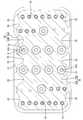
また、ハウジング本体11の後面には、ゴム栓収容部20が開口して形成されている。ゴム栓収容部20の周囲は、ハウジング本体11の後端部に突成された薄肉の周壁21によって取り囲まれている。周壁21は、図2に示すように、高さ方向に沿って延びる互いにほぼ平行な一対の縦板22と、幅方向に沿って延びる互いにほぼ平行な一対の横板23と、両縦板22と両横板23の端部同士をつなぎつつ4隅に位置する円弧状の曲板24とからなる。両横板23の外側には、パネルロック部15の解除操作部17が配置されている。また、両縦板22の外面には、高さ方向に一対ずつのホルダロック受け部25が突出して形成されている。 Further, a rubber
そして、両縦板22のそれぞれの内面には、位置決め受け部26が形成されている。位置決め受け部26は、ゴム栓収容部20内に円弧状に膨出する形態をなし、その内部に空間部27を保有している。この場合、後方から見て右側の位置決め受け部26は、周壁21の高さ方向中央よりも上方に位置し、後方から見て左側の位置決め受け部26は、周壁21の高さ方向中央よりも下方に位置している。そして、両位置決め受け部26は、各キャビティ13と同様、ハウジング本体11の中央部を中心とする点対称の位置に配置されている。 A
続いて、ゴム栓50について説明すると、ゴム栓50はシリコンゴム等のゴム製であって、図6ないし図8に示すように、高さ方向に長いマット状のゴム栓本体51を有している。ゴム栓本体51は、ゴム栓収容部20に挿入されるものであって、ゴム栓収容部20に適合して嵌合可能な大きさを有している。そして、ゴム栓本体51には、ゴム栓50がゴム栓収容部20に収容された状態で、各キャビティ13と連通する複数の電線挿通孔52が形成されている。各電線挿通孔52は、各キャビティ13と対応して配置され、大型から小型の複数種によって構成されている。そして、各電線挿通孔52の内周には、複数条の内周リップ53が周回して形成されている。ゴム栓本体51の裏面には、各電線挿通孔52の孔周りに、端子金具80を案内可能な誘い込み面54がラッパ状に拡開して形成されている。 Next, the
ゴム栓本体51の周縁部には、厚み方向(前後方向)に2条のリップ55が並んで形成されている。両リップ55は、ゴム栓本体51の周縁部に全周に亘って周回して形成されている。両リップ55の間には、断面ほぼU字状の谷部56が形成されている。また、ゴム栓本体51の周縁部における両リップ55の前後両外側には、両リップ55に段差状に連なるフラット面57が前後方向に沿って形成されている。谷部56の底部は、ゴム栓本体51においてフラット面57よりも内側の位置まで深く切り込まれている。 Two
また、ゴム栓本体51の周縁部には、位置決め部58が凹み形成されている。位置決め部58は、ゴム栓本体51の高さ方向に延びる両側縁のそれぞれに配置され、後方から見て右側の位置決め部58は、ゴム栓本体51の高さ方向中央よりも上方に位置し、後方から見て左側の位置決め部58は、ゴム栓本体51の高さ方向中央よりも下方に位置している。両位置決め部58は、ゴム栓本体51の中央部を中心として互いに点対称の位置に配置されている。 In addition, a
そして、位置決め部58は、位置決め本体部58Aと、凹部58Bとで構成されている。位置決め本体部58Aは、後方及び前方から見てほぼU字状をなし、ゴム栓本体51の全肉厚範囲に亘って切り欠かれている。両リップ55は、位置決め本体部58Aとともにゴム栓本体51の内方に凹む部分を有している。 And the
凹部58Bは、位置決め本体部58Aに連なる谷部56の部分と、その底部からゴム栓本体51の内側に深く凹む部分とで構成されている。また、谷部56の底部には、高さ方向に間隔をあけて複数の切除部59が凹み形成されている。切除部59は、凹部58Bと同様、ゴム栓本体51の内側に深く凹む形態であって、凹部58Bと高さ方向に並んで配置されている。切除部59及び凹部58Bは、ゴム栓本体51の両側縁寄りに配置された端部側の電線挿通孔52Aを取り囲むように形成されている。 The
具体的には、ゴム栓本体51の両側縁部には、大型の端部側の電線挿通孔52Aを高さ方向に挟んだ一方の側に、凹部58Bが形成され、他方の側に、切除部59が形成されている。この端部側の電線挿通孔52Aを挟んだ両側の切除部59及び凹部58Bは、互いに同じ深さ位置に底面を有している。端部側の電線挿通孔52Aの周りにおけるゴム栓50の両側縁寄りのほぼ半周部分は、切除部59及び凹部58Bで取り囲まれることにより、周方向にほぼ一定の径寸法Rを有することとなる。なお、本実施形態に係るゴム栓50は、全体として、その中央部を中心として点対称な形状をなしている。 Specifically, at both side edges of the
ホルダ70は合成樹脂製であって、図3及び図4に示すように、全体として高さ方向に長い板状をなしている。ホルダ70には、各電線挿通孔52と対応する位置に、複数の電線通し孔72が貫通して形成されている。各電線通し孔72は、端子本体82の断面外形と対応する略矩形状をなし、電線90を遊挿可能な大きさを有している。また、ホルダ70の両側縁には、高さ方向に一対ずつのホルダロック部73が後方へ突出して形成されている。ホルダ70の幅方向に延びる上下両端縁には、パネルロック部15の解除操作部17が進入する逃がし凹部74が切り欠いて形成されている。かかるホルダ70は、ゴム栓収容部20に挿入されたゴム栓50を後方から覆うようにハウジング10に装着され、正規装着時に、各ホルダロック部73が対応するホルダロック受け部25を弾性的に係止することにより、ハウジング10に保持されるようになっている。 The
本実施形態に係る防水コネクタの構成は上述の通りであり、次に、ゴム栓50の製造方法について説明する。
ゴム栓50を成形するにあたり、図9に示すように、一対の金型100と、スライド型200とが用いられる。両金型100は、ゴム栓50の表裏両面、各電線挿通孔52、位置決め本体部58A、及びフラット面57等を成形するためのものであって、両金型100のうちの少なくとも一方が可動型102とされ、この可動型102が固定型101に対して接近・離間する前後方向に移動可能とされている。これに対し、スライド型200は、凹部58B、切除部59、及び谷部56を成形するためのものであって、両金型100の移動方向となる前後方向とほぼ直交する方向に移動可能とされている。The structure of the waterproof connector according to the present embodiment is as described above. Next, a method for manufacturing the
In forming the
まず、両金型100及びスライド型200が閉じられ、その内部空間にゴム材からなる樹脂が充填硬化される。このとき、両金型100によってゴム栓50の表裏両面、各電線挿通孔52、及びフラット面57が成形され、スライド型200によって凹部58B、切除部59、及び谷部56が成形される。次いで、ゴム栓の成形後、可動型102が固定型101から離間する方向に移動させられ、ゴム栓50の表裏両面等が露出される。このとき、スライド型200は、凹部58B、切除部59、及び谷部56に入り込んだままの状態に保たれ、可動型102にゴム栓50が付着して追従するのが回避される。両金型100の移動後、スライド型200がゴム栓50の平面方向に沿う方向に移動させられ、谷部56等が露出される。かくして、両金型100及びスライド型200が脱型され、ゴム栓50が成形される。 First, both the
次に、防水コネクタの組み付け方法について説明する。
まず、図1に示すように、ハウジング10のゴム栓収容部20に後方からゴム栓50を嵌入させる。このとき、位置決め受け部26に位置決め部58の位置決め本体部58Aが適合して嵌入され、正規深さで嵌入されるに伴い、ゴム栓50の両リップ55がゴム栓収容部20の周壁21内面に弾性的に密着される。次いで、図4に示すように、ゴム栓50を後方から覆うようにして、ハウジング10にホルダ70を装着させる。ホルダ70がホルダロック部73とホルダロック受け部25との係止によってハウジング10に保持されることにより、ゴム栓50のハウジング10からの抜け止めがなされる。続いて、図5に示すように、ハウジング10のキャビティ13内に電線90付きの端子金具80を挿入する。端子金具80は、電線通し孔72から電線挿通孔52を経てキャビティ13内に挿入される。端子金具80がキャビティ13内に正規挿入されると、ゴム栓50の内周リップ53が電線90の外周面に弾性的に密着される。これにより、ゴム栓50と電線90との間が液密にシールされ、さらにゴム栓50を介して電線90とハウジング10との間が液密にシールされる。Next, a method for assembling the waterproof connector will be described.
First, as shown in FIG. 1, the
上記の場合において、仮に、ゴム栓50が表裏反転の姿勢をとってゴム栓収容部20に挿入されようとすると、位置決め受け部26が位置決め部58に対応せずにゴム栓本体51の両側縁に干渉し、もってゴム栓50のゴム栓収容部20への挿入が規制される。このため、ゴム栓50がその表裏面を誤ってゴム栓収容部20に挿入されることがなく、ゴム栓50の装着が適正になされる。 In the above case, if the
また、本実施形態の場合、ゴム栓50が点対称の形状とされ、ゴム栓50がその中央部を中心として180後回転しても、回転前と同じ形態となり、かつハウジング10の位置決め受け部26が位置決め部58と対応する位置に配置されているため、ゴム栓50の上下の向き等を気にすることなく、ゴム栓50の装着を行える。したがって、ゴム栓50装着時の作業負担が軽減される。 Further, in the case of this embodiment, the
また、ゴム栓50の成形後、スライド型200が両リップ55間の谷部56に入り込んだままの状態で金型100の型開きがなされるから、スライド型200の引っ掛かりにより、ゴム栓50が可動型102に付着するのが確実に防止される。 Further, after the
この場合、位置決め部58の凹部58Bがスライド型200によって成形されるため、凹部58Bを成形するための専用型が不要となり、金型100の構成が複雑になるのが回避される。さらに、切除部59がスライド型200によって成形されるため、切除部59を成形するための専用型が不要となり、金型100の構成が複雑になるのが回避される。 In this case, since the
また、ゴム栓50の端部側の電線挿通孔52Aが凹部58Bと切除部59との間に位置することにより、端部側の電線挿通孔52Aの周りでゴム栓50の端部寄りのほぼ半周領域の径方向に関する寸法Rがほぼ等しくなっているため、端部側の電線挿通孔52Aに通された電線90の半周領域に対してゴム栓50からほぼ均一な弾性反力が付与される。したがって、電線90の周りがバランス良くシールされる。 Further, since the
<他の実施形態>
本発明は上記記述及び図面によって説明した実施形態に限定されるものではなく、例えば次のような実施形態も本発明の技術的範囲に含まれる。
(1)ホルダの前面にゴム栓の収容領域が凹み形成され、その周壁内面に位置決め受け部が形成されるものであってもよい。
(2)切除部が凹部よりも深く凹み形成されるものであってもよい。これによれば、切除部を成形するスライド型の部分が凹部を成形するスライド型の部分よりも深い引っ掛かりとなるため、ゴム栓が可動型に付着したまま型開きされるのがより確実に回避される。
(3)空きキャビティと対応する電線挿通孔の内部がホルダから突出する突起によって閉塞される構成であってもよい。
(4)ハウジングは、タブを有さない雌端子金具を収容可能なキャビティを有する雌型ハウジングであってもよい。<Other embodiments>
The present invention is not limited to the embodiments described with reference to the above description and drawings. For example, the following embodiments are also included in the technical scope of the present invention.
(1) A rubber stopper accommodation region may be formed in a recess on the front surface of the holder, and a positioning receiving portion may be formed on the inner surface of the peripheral wall.
(2) The cut portion may be formed deeper than the recess. According to this, since the portion of the slide mold that molds the cut portion is caught deeper than the portion of the slide mold that molds the recess, it is more reliably avoided that the rubber stopper remains attached to the movable mold and the mold is opened. Is done.
(3) The inside of the electric wire insertion hole corresponding to the empty cavity may be closed by a protrusion protruding from the holder.
(4) The housing may be a female housing having a cavity that can accommodate a female terminal fitting having no tab.
10…ハウジング
13…キャビティ
20…ゴム栓収容部
26…位置決め受け部
50…ゴム栓
52…電線挿通孔
55…リップ
56…谷部
58…位置決め部
58B…凹部
59…切除部
70…ホルダ
80…端子金具
90…電線
100…金型
200…スライド型DESCRIPTION OF
Claims (3)
Translated fromJapanese前記ゴム栓収容部に収容され、前記各キャビティと連通する電線挿通孔を有するゴム栓と、
前記ハウジングに装着され、前記ゴム栓の抜け止めを行うホルダとを備えた防水コネクタであって、
前記ゴム栓には、位置決め部が形成され、
前記ゴム栓収容部又は前記ホルダには、前記ゴム栓が、前記ゴム栓収容部又は前記ホルダに対し、正規の姿勢をとる場合には前記位置決め部と嵌合して装着される一方、不正な姿勢をとる場合には前記位置決め部と干渉して前記ゴム栓の装着を不能とする位置決め受け部が形成され、
前記ゴム栓の周縁部には、共に全周に沿った2条のリップが厚み方向に並んで形成され、前記位置決め部が、前記両リップの間の谷部においてその深さ方向に凹み形成される凹部を含み、前記凹部が、前記ゴム栓の成形時にこのゴム栓の平面方向に沿う方向へ進退可能なスライド型によって形成されていることを特徴とする防水コネクタ。A housing having a cavity capable of accommodating a terminal fitting and having a rubber plug accommodating portion opened on the rear surface;
A rubber plug that is housed in the rubber plug housing portion and has a wire insertion hole that communicates with each of the cavities;
A waterproof connector provided with a holder that is attached to the housing and prevents the rubber stopper from being detached,
The rubber plug has a positioning portion,
The rubber plug housing portion or the holder is fitted with the positioning portion when the rubber plug takes a normal posture with respect to the rubber plug housing portion or the holder. When taking a posture, a positioning receiving portion is formed which interferes with the positioning portion and makes it impossible to attach the rubber plug,
Two lips along the entire circumference are formed side by side in the thickness direction on the peripheral edge of the rubber plug, and the positioning portion is recessed in the depth direction at the valley between the two lips. The waterproof connector is characterized in that therecess is formed by a slide mold capable of moving back and forth in a direction along a plane direction of the rubber plug when the rubber plug is molded .
前記位置決め部が、前記ゴム栓の周縁部における点対称の位置において内方へ全肉厚範囲に亘って凹み形成され、
前記位置決め受け部が、前記ゴム栓収容部の周壁内面又は前記ホルダの周壁内面における前記位置決め部と対応する点対称の位置に配置されている請求項1記載の防水コネクタ。The cavity is constituted by a plurality of types capable of accommodating a plurality of types of terminal fittings, and when the rubber plug accommodating portion is viewed from the rear, the cavities are arranged at point-symmetric positions,
The positioning portion is formed in a concave shape over the entire thickness range inward at a point-symmetrical position in the peripheral portion of the rubber plug,
The waterproof connector according to claim 1, wherein the positioning receiving portion is disposed at a point-symmetrical position corresponding to the positioning portion on the inner surface of the peripheral wall of the rubber plug housing portion or the inner surface of the peripheral wall of the holder.
Priority Applications (4)
| Application Number | Priority Date | Filing Date | Title |
|---|---|---|---|
| JP2010214310AJP5569297B2 (en) | 2010-09-24 | 2010-09-24 | Waterproof connector |
| KR1020110094099AKR20120031443A (en) | 2010-09-24 | 2011-09-19 | Waterproof connector and method of producing rubber stopper |
| US13/235,827US8568168B2 (en) | 2010-09-24 | 2011-09-19 | Waterproof connector and method of producing rubber stopper |
| CN201110285209.3ACN102544867B (en) | 2010-09-24 | 2011-09-19 | Waterproof connector and method of producing rubber stopper |
Applications Claiming Priority (1)
| Application Number | Priority Date | Filing Date | Title |
|---|---|---|---|
| JP2010214310AJP5569297B2 (en) | 2010-09-24 | 2010-09-24 | Waterproof connector |
Publications (2)
| Publication Number | Publication Date |
|---|---|
| JP2012069426A JP2012069426A (en) | 2012-04-05 |
| JP5569297B2true JP5569297B2 (en) | 2014-08-13 |
Family
ID=45871099
Family Applications (1)
| Application Number | Title | Priority Date | Filing Date |
|---|---|---|---|
| JP2010214310AExpired - Fee RelatedJP5569297B2 (en) | 2010-09-24 | 2010-09-24 | Waterproof connector |
Country Status (4)
| Country | Link |
|---|---|
| US (1) | US8568168B2 (en) |
| JP (1) | JP5569297B2 (en) |
| KR (1) | KR20120031443A (en) |
| CN (1) | CN102544867B (en) |
Families Citing this family (16)
| Publication number | Priority date | Publication date | Assignee | Title |
|---|---|---|---|---|
| JP5704031B2 (en)* | 2011-09-24 | 2015-04-22 | 住友電装株式会社 | connector |
| JP6292468B2 (en)* | 2014-01-31 | 2018-03-14 | 住友電装株式会社 | connector |
| ES2768272T3 (en)* | 2014-03-05 | 2020-06-22 | Yazaki Europe Ltd | Molding tool |
| CN103887647B (en)* | 2014-03-21 | 2017-05-03 | 深圳君泽电子有限公司 | Earphone connector, manufacturing method thereof and mobile terminal with earphone connector |
| CN107925188B (en)* | 2015-07-29 | 2020-09-15 | 莫列斯有限公司 | Connector and frame thereof |
| DK3151582T3 (en) | 2015-09-30 | 2020-10-12 | Apple Inc | HEADPHONE WITH CHARGING SYSTEM CASE |
| JP6453747B2 (en)* | 2015-12-02 | 2019-01-16 | 矢崎総業株式会社 | Elastic seal member and connector |
| JP2018120666A (en)* | 2017-01-23 | 2018-08-02 | 住友電装株式会社 | Waterproof connector |
| JP6939612B2 (en)* | 2018-02-01 | 2021-09-22 | 住友電装株式会社 | Waterproof connector |
| KR20200008269A (en) | 2018-07-16 | 2020-01-28 | 한국단자공업 주식회사 | Waterproof connector |
| US11172101B1 (en) | 2018-09-20 | 2021-11-09 | Apple Inc. | Multifunction accessory case |
| EP3629426A1 (en)* | 2018-09-27 | 2020-04-01 | Tyco Electronics Japan G.K. | Seal member and connector assembly |
| US11171440B2 (en)* | 2019-03-20 | 2021-11-09 | Aptiv Technologies Limited | Backing plate for mounting and sealing an electrical connector to an intermediate surface |
| JP2021131994A (en)* | 2020-02-20 | 2021-09-09 | 住友電装株式会社 | connector |
| US11735858B2 (en)* | 2020-07-14 | 2023-08-22 | J.S.T. Corporation | Elastomer seal spring |
| CN115143305B (en)* | 2021-03-31 | 2023-12-26 | 浙江三花汽车零部件有限公司 | Fluid control assembly and method of making the same |
Family Cites Families (23)
| Publication number | Priority date | Publication date | Assignee | Title |
|---|---|---|---|---|
| JPH02119371U (en)* | 1989-03-13 | 1990-09-26 | ||
| US4998896A (en)* | 1989-09-25 | 1991-03-12 | Amp Incorporated | Sealed stamped and formed pin |
| US4944688A (en)* | 1989-09-25 | 1990-07-31 | Amp Incorporated | Programmable sealed connector |
| US5145410A (en)* | 1990-08-06 | 1992-09-08 | Yazaki Corporation | Waterproof connector |
| US5266045A (en)* | 1991-10-28 | 1993-11-30 | Yazaki Corporation | Waterproof connector |
| JPH08180928A (en)* | 1994-10-24 | 1996-07-12 | Yazaki Corp | Waterproof connector |
| JPH08298151A (en)* | 1995-04-26 | 1996-11-12 | Sumitomo Wiring Syst Ltd | Tube unit holding structure |
| JP4064537B2 (en)* | 1998-06-30 | 2008-03-19 | 矢崎総業株式会社 | Rear cover and method for forming elastic seal member in rear cover |
| US6193549B1 (en)* | 1999-04-13 | 2001-02-27 | Sumitomo Wiring Systems, Ltd. | Waterproof connector for electrical terminals |
| US6447331B1 (en)* | 1999-05-19 | 2002-09-10 | Sumitomo Wiring Systems, Ltd. | Joint connector and method of producing joint connector |
| JP2000353567A (en)* | 1999-06-10 | 2000-12-19 | Yazaki Corp | Waterproof connector |
| US6341983B1 (en)* | 2000-04-05 | 2002-01-29 | Delphi Technologies, Inc. | Co-molded seal and strain relief for automotive electrical connections |
| JP3646867B2 (en)* | 2000-09-29 | 2005-05-11 | 住友電装株式会社 | connector |
| JP4214898B2 (en)* | 2003-11-27 | 2009-01-28 | 住友電装株式会社 | Waterproof connector |
| JP2005317385A (en) | 2004-04-28 | 2005-11-10 | Tyco Electronics Amp Kk | Waterproof connector and sealing member therefor |
| US7351102B2 (en)* | 2004-05-21 | 2008-04-01 | Delphi Technologies, Inc. | Electrical connector with terminal position assurance |
| JP2006059595A (en)* | 2004-08-18 | 2006-03-02 | Sumitomo Wiring Syst Ltd | Water-proof connector |
| JP2006140019A (en)* | 2004-11-11 | 2006-06-01 | Tyco Electronics Amp Kk | Waterproof connector and seal member |
| US7371115B1 (en)* | 2006-12-15 | 2008-05-13 | Delphi Technologies, Inc. | Mat seal device |
| JP5056404B2 (en)* | 2007-12-26 | 2012-10-24 | 住友電装株式会社 | connector |
| JP5083012B2 (en)* | 2008-04-18 | 2012-11-28 | 住友電装株式会社 | Waterproof connector |
| CN102257681B (en)* | 2008-11-07 | 2013-09-04 | 富加宜汽车控股公司 | Sealed electrical connector |
| US8257111B1 (en)* | 2011-03-03 | 2012-09-04 | Delphi Technologies, Inc. | Sealed electrical splice assembly |
- 2010
- 2010-09-24JPJP2010214310Apatent/JP5569297B2/ennot_activeExpired - Fee Related
- 2011
- 2011-09-19KRKR1020110094099Apatent/KR20120031443A/ennot_activeAbandoned
- 2011-09-19CNCN201110285209.3Apatent/CN102544867B/ennot_activeExpired - Fee Related
- 2011-09-19USUS13/235,827patent/US8568168B2/enactiveActive
Also Published As
| Publication number | Publication date |
|---|---|
| CN102544867B (en) | 2014-10-08 |
| CN102544867A (en) | 2012-07-04 |
| JP2012069426A (en) | 2012-04-05 |
| KR20120031443A (en) | 2012-04-03 |
| US20120077377A1 (en) | 2012-03-29 |
| US8568168B2 (en) | 2013-10-29 |
Similar Documents
| Publication | Publication Date | Title |
|---|---|---|
| JP5569297B2 (en) | Waterproof connector | |
| JP4849109B2 (en) | Receptacle connector and manufacturing method thereof | |
| JP5972766B2 (en) | Hinge structure | |
| CN110098527B (en) | Wire cover and connector | |
| CN104103942B (en) | Connector | |
| JP5454445B2 (en) | connector | |
| CN110073553A (en) | Connector with serum cap | |
| AU2015401870A1 (en) | Wire housing protector | |
| TW201637293A (en) | Socket connector | |
| JP5136861B2 (en) | Shield connector | |
| JP2016219235A (en) | connector | |
| CN110165501B (en) | Connector and connector device | |
| CN103384908A (en) | Fuse box | |
| CN109863648B (en) | male connector | |
| JP7513955B2 (en) | connector | |
| CN110165477B (en) | Connector with a locking member | |
| CN103682790B (en) | Connector | |
| JP6720236B2 (en) | Connecting terminal | |
| EP2795737B1 (en) | Connector assembly with seal protection cap | |
| JP6358102B2 (en) | connector | |
| JP2007165191A (en) | Connector | |
| JP2015141859A (en) | card edge connector | |
| JP2016006725A (en) | Lever type connector | |
| JP5257347B2 (en) | connector | |
| JP6490726B2 (en) | Vehicle side connector |
Legal Events
| Date | Code | Title | Description |
|---|---|---|---|
| A621 | Written request for application examination | Free format text:JAPANESE INTERMEDIATE CODE: A621 Effective date:20121225 | |
| A977 | Report on retrieval | Free format text:JAPANESE INTERMEDIATE CODE: A971007 Effective date:20131126 | |
| A131 | Notification of reasons for refusal | Free format text:JAPANESE INTERMEDIATE CODE: A131 Effective date:20140107 | |
| A521 | Written amendment | Free format text:JAPANESE INTERMEDIATE CODE: A523 Effective date:20140228 | |
| TRDD | Decision of grant or rejection written | ||
| A01 | Written decision to grant a patent or to grant a registration (utility model) | Free format text:JAPANESE INTERMEDIATE CODE: A01 Effective date:20140527 | |
| A61 | First payment of annual fees (during grant procedure) | Free format text:JAPANESE INTERMEDIATE CODE: A61 Effective date:20140609 | |
| R150 | Certificate of patent or registration of utility model | Ref document number:5569297 Country of ref document:JP Free format text:JAPANESE INTERMEDIATE CODE: R150 | |
| LAPS | Cancellation because of no payment of annual fees |