JP5565398B2 - Inspection target - Google Patents
Inspection targetDownload PDFInfo
- Publication number
- JP5565398B2 JP5565398B2JP2011218510AJP2011218510AJP5565398B2JP 5565398 B2JP5565398 B2JP 5565398B2JP 2011218510 AJP2011218510 AJP 2011218510AJP 2011218510 AJP2011218510 AJP 2011218510AJP 5565398 B2JP5565398 B2JP 5565398B2
- Authority
- JP
- Japan
- Prior art keywords
- separation
- component
- flow path
- liquid
- centrifugal force
- Prior art date
- Legal status (The legal status is an assumption and is not a legal conclusion. Google has not performed a legal analysis and makes no representation as to the accuracy of the status listed.)
- Expired - Fee Related
Links
Images


Classifications
- B—PERFORMING OPERATIONS; TRANSPORTING
- B01—PHYSICAL OR CHEMICAL PROCESSES OR APPARATUS IN GENERAL
- B01L—CHEMICAL OR PHYSICAL LABORATORY APPARATUS FOR GENERAL USE
- B01L3/00—Containers or dishes for laboratory use, e.g. laboratory glassware; Droppers
- B01L3/50—Containers for the purpose of retaining a material to be analysed, e.g. test tubes
- B01L3/502—Containers for the purpose of retaining a material to be analysed, e.g. test tubes with fluid transport, e.g. in multi-compartment structures
- B01L3/5027—Containers for the purpose of retaining a material to be analysed, e.g. test tubes with fluid transport, e.g. in multi-compartment structures by integrated microfluidic structures, i.e. dimensions of channels and chambers are such that surface tension forces are important, e.g. lab-on-a-chip
- B01L3/502753—Containers for the purpose of retaining a material to be analysed, e.g. test tubes with fluid transport, e.g. in multi-compartment structures by integrated microfluidic structures, i.e. dimensions of channels and chambers are such that surface tension forces are important, e.g. lab-on-a-chip characterised by bulk separation arrangements on lab-on-a-chip devices, e.g. for filtration or centrifugation
- B—PERFORMING OPERATIONS; TRANSPORTING
- B01—PHYSICAL OR CHEMICAL PROCESSES OR APPARATUS IN GENERAL
- B01L—CHEMICAL OR PHYSICAL LABORATORY APPARATUS FOR GENERAL USE
- B01L3/00—Containers or dishes for laboratory use, e.g. laboratory glassware; Droppers
- B01L3/50—Containers for the purpose of retaining a material to be analysed, e.g. test tubes
- B01L3/502—Containers for the purpose of retaining a material to be analysed, e.g. test tubes with fluid transport, e.g. in multi-compartment structures
- B01L3/5027—Containers for the purpose of retaining a material to be analysed, e.g. test tubes with fluid transport, e.g. in multi-compartment structures by integrated microfluidic structures, i.e. dimensions of channels and chambers are such that surface tension forces are important, e.g. lab-on-a-chip
- B01L3/50273—Containers for the purpose of retaining a material to be analysed, e.g. test tubes with fluid transport, e.g. in multi-compartment structures by integrated microfluidic structures, i.e. dimensions of channels and chambers are such that surface tension forces are important, e.g. lab-on-a-chip characterised by the means or forces applied to move the fluids
- B—PERFORMING OPERATIONS; TRANSPORTING
- B01—PHYSICAL OR CHEMICAL PROCESSES OR APPARATUS IN GENERAL
- B01L—CHEMICAL OR PHYSICAL LABORATORY APPARATUS FOR GENERAL USE
- B01L2200/00—Solutions for specific problems relating to chemical or physical laboratory apparatus
- B01L2200/06—Fluid handling related problems
- B01L2200/0605—Metering of fluids
- B—PERFORMING OPERATIONS; TRANSPORTING
- B01—PHYSICAL OR CHEMICAL PROCESSES OR APPARATUS IN GENERAL
- B01L—CHEMICAL OR PHYSICAL LABORATORY APPARATUS FOR GENERAL USE
- B01L2200/00—Solutions for specific problems relating to chemical or physical laboratory apparatus
- B01L2200/06—Fluid handling related problems
- B01L2200/0621—Control of the sequence of chambers filled or emptied
- B—PERFORMING OPERATIONS; TRANSPORTING
- B01—PHYSICAL OR CHEMICAL PROCESSES OR APPARATUS IN GENERAL
- B01L—CHEMICAL OR PHYSICAL LABORATORY APPARATUS FOR GENERAL USE
- B01L2300/00—Additional constructional details
- B01L2300/08—Geometry, shape and general structure
- B01L2300/0809—Geometry, shape and general structure rectangular shaped
- B01L2300/0816—Cards, e.g. flat sample carriers usually with flow in two horizontal directions
- B—PERFORMING OPERATIONS; TRANSPORTING
- B01—PHYSICAL OR CHEMICAL PROCESSES OR APPARATUS IN GENERAL
- B01L—CHEMICAL OR PHYSICAL LABORATORY APPARATUS FOR GENERAL USE
- B01L2300/00—Additional constructional details
- B01L2300/08—Geometry, shape and general structure
- B01L2300/0861—Configuration of multiple channels and/or chambers in a single devices
- B01L2300/0864—Configuration of multiple channels and/or chambers in a single devices comprising only one inlet and multiple receiving wells, e.g. for separation, splitting
- B—PERFORMING OPERATIONS; TRANSPORTING
- B01—PHYSICAL OR CHEMICAL PROCESSES OR APPARATUS IN GENERAL
- B01L—CHEMICAL OR PHYSICAL LABORATORY APPARATUS FOR GENERAL USE
- B01L2400/00—Moving or stopping fluids
- B01L2400/04—Moving fluids with specific forces or mechanical means
- B01L2400/0403—Moving fluids with specific forces or mechanical means specific forces
- B01L2400/0409—Moving fluids with specific forces or mechanical means specific forces centrifugal forces
- B—PERFORMING OPERATIONS; TRANSPORTING
- B01—PHYSICAL OR CHEMICAL PROCESSES OR APPARATUS IN GENERAL
- B01L—CHEMICAL OR PHYSICAL LABORATORY APPARATUS FOR GENERAL USE
- B01L2400/00—Moving or stopping fluids
- B01L2400/06—Valves, specific forms thereof
- B01L2400/0688—Valves, specific forms thereof surface tension valves, capillary stop, capillary break
Landscapes
- Chemical & Material Sciences (AREA)
- Health & Medical Sciences (AREA)
- Dispersion Chemistry (AREA)
- Analytical Chemistry (AREA)
- General Health & Medical Sciences (AREA)
- Hematology (AREA)
- Clinical Laboratory Science (AREA)
- Chemical Kinetics & Catalysis (AREA)
- Life Sciences & Earth Sciences (AREA)
- Molecular Biology (AREA)
- Automatic Analysis And Handling Materials Therefor (AREA)
Description
Translated fromJapanese本発明は、検査対象受体に関し、詳細には、比重の異なる成分を含んだ液体を分離して、例えば、化学的、医学的、生物学的な検査を行うための検査対象受体に関する。 The present invention relates to a test subject receiver, and in particular, to a test subject receiver for separating liquids containing components having different specific gravities and performing, for example, chemical, medical, and biological tests.
従来、化学的、医学的、生物学的な検査の分野で、DNA(Deoxyribo Nucleic Acid)や酵素、抗原、抗体、タンパク質、ウィルス、細胞などの生体物質、及び化学物質等を検知、定量する場合に使用するマイクロチップ又は検査チップと呼ばれる検査対象受体が提案されている。この検査対象受体では、内部の液体供給路に検査対象の液体を注入して、当該検査対象受体を水平に保持して公転させて、当該公転により生じる遠心力を利用して、検査対象受体内に形成された流路内の複数の混合槽に液体を移動させ検査を行うようになっている(例えば、特許文献1参照)。この検査対象受体では、血液に遠心力付加し、分離部で血漿(第一成分)と血球(第二成分)と分離し、血漿の一部を取り出すようになっている。この検査対象受体では、血漿の分離後、血球を含まない血漿のみを取り出すために、分離部を屈曲させて変形している。 Conventionally, in the field of chemical, medical, and biological examinations, when detecting and quantifying DNA (Deoxyribo Nucleic Acid), enzymes, antigens, antibodies, proteins, viruses, cells and other biological materials, and chemical substances An inspection object receiver called a microchip or an inspection chip used for the above has been proposed. In this inspection object receptacle, the liquid to be inspected is injected into the internal liquid supply path, the inspection object receiver is held horizontally and revolved, and the centrifugal force generated by the revolution is used to inspect the inspection object. The inspection is performed by moving the liquid to a plurality of mixing tanks in the flow path formed in the receiver (for example, see Patent Document 1). In this test subject receiver, centrifugal force is applied to blood, and plasma (first component) and blood cells (second component) are separated by a separation unit, and a part of plasma is taken out. In this test subject receiver, after separating the plasma, the separating portion is bent and deformed in order to take out only the plasma not containing blood cells.
しかしながら、特許文献1に記載の発明の検査対象受体は、血漿の分離後に、血漿の取り出し方向と同じ方向に遠心力が掛かった場合に、分離部に残留した血球等の残留成分が次工程に流れ出すという問題点があった。この場合には、血漿に残留成分が混ざり、検査の精度が下がるという問題点があった。 However, in the test subject receptor of the invention described in
本発明は、上記課題を解決するためになされたものであり、分離部で分離した残留成分が次工程に流れ出すことを防止できる検査対象受体を実現することを目的とする。 The present invention has been made to solve the above-described problems, and an object of the present invention is to realize an inspection target receptacle that can prevent a residual component separated by a separation unit from flowing to the next process.
上記目的を達成するために、本発明の第1の態様の検査対象受体では、少なくとも、液体の流路が表面に形成された基板と前記流路を覆う蓋部とを備え、前記流路と前記蓋部の裏面とから構成された流体回路を内部に備えた検査対象受体であって、前記流体回路は、少なくとも、遠心力により前記液体の成分を分離成分と当該分離成分より比重の大きい残留成分とに分離する分離部と、前記分離部から次工程へ前記分離成分を導く第一流路と、前記分離部で分離された前記分離成分が前記第一流路により前記分離部から前記次工程へ移行する際に前記分離部から流れ出る前記液体の一部を保持する保持部と、前記分離部から前記保持部へ前記残留成分を導く第二流路と、を備え、前記第二流路は前記分離部の前記第一流路側の側壁部に接続され、前記側壁部は、前記分離部において前記分離成分と前記残留成分とに分離される際の遠心力の方向と、前記分離成分を前記第一流路を介して前記次工程へ導く際の遠心力の方向との間の方向に延設されていることを特徴とする。
In order to achieve the above object, the inspection object receiver according to the first aspect of the present invention includes at least a substrate having a liquid flow channel formed on a surface thereof and a lid that covers the flow channel. And a back surface of the lid, the test subject receiving body having a fluid circuit formed therein, wherein the fluid circuit has at least a separation component and a specific gravity greater than the separation component by centrifugal force. A separation part that separates into large residual components; a first channel that guides the separation component from the separation part to the next process; and the separation component separated in the separation part is separated from the separation part by the first channel from the separation part. A holding part that holds a part of the liquid flowing out from the separation part when the process proceeds to a process; and asecond flow path that guides the residual component from the separation part to the holding part, andthe second flow path Is connected to the side wall portion on the first flow path side of the separation portion. The side wall portion has a centrifugal force direction when the separation component is separated into the separation component and the residual component in the separation portion, and a centrifugal force when the separation component is guided to the next step through the first flow path. It is characterized byextending ina direction between the two directions .
この構成の検査対象受体では、分離部から分離成分次工程へ分離成分を移行する際に前記分離部から流れ出る液体の一部であり分離成分より比重の大きい残留成分を保持部にトラップすることができる。従って、分離部で分離した残留成分が次工程に流れ出すことを防止でき、検査の精度を高めることができる。 In the inspection target receiver having this configuration, when the separated component is transferred from the separation unit to the separated component next process, a residual component that is a part of the liquid flowing out of the separation unit and has a higher specific gravity than the separated component is trapped in the holding unit. Can do. Therefore, it is possible to prevent the residual component separated by the separation unit from flowing out to the next process, and to increase the accuracy of the inspection.
また、遠心力の付与による検査対象の液体を溜める液溜部から前記分離部へ前記液体の導入時及び前記分離部での前記分離成分と前記残留成分の分離時において、前記側壁部と前記第二流路の接続部から前記遠心力の方向に伸ばした延長線と前記第二流路の延設方向との成す角度は、90度以上であるようにしても良い。この場合には、遠心力により分離部に液体を流し込むときに、液体が第二流路に流れ込むことを防止できる。
Further, at the time of separation of the separated components and the residual components of the introduction time and the separation portion of the liquid to the separating portion from the liquid reservoir for storing the inspected liquid by thecentrifugal force applied, the said side wall first The angle formed by the extension line extending inthe direction of the centrifugal force from the connecting portion of the two flow paths and the extending direction of the second flow path may be 90 degrees or more. In this case, it is possible to prevent the liquid from flowing into the second flow path when the liquid is poured into the separation portion by centrifugal force.
また、前記分離部と前記第二流路との接続部の位置は、前記分離部での前記分離成分と前記残留成分との分離時の遠心力の方向において、前記分離部の中央よりも上流側になるようにしても良い。この場合には、第二流路の入り口は分離成分側に位置するので、残留成分による第二流路の詰まりを防止することができる。
On addition, the position of the connection portion between the separating portion and said second flow path,in the direction of the centrifugal force upon separation of the separated components and the residual components in the separationsection,thanthe center of the separating portion You may make it the flow side. In this case, since the entrance of the second flow path is located on the separation component side, the clogging of the second flow path due to residual components can be prevented.
また、前記分離部での前記分離成分と前記残留成分との分離後に前記分離成分が溜まる側の前記分離部の側壁部に前記第二流路が接続されても良い。この場合には、第二流路の入り口は分離成分側に位置するので、残留成分による第二流路の詰まりを防止することができる。 Further, the second flow path may be connected to a side wall portion of the separation portion on a side where the separation component is accumulated after the separation component and the residual component are separated in the separation portion. In this case, since the entrance of the second flow path is located on the separation component side, the clogging of the second flow path due to residual components can be prevented.
また、前記第二流路は前記第一流路に向かって延設されても良い。この場合には、分離成分が第一流路に流れる前に、第二流路を介して保持部に分離成分が流れ込むことを防止できる。
Further, the second flow path may be extended toward the first flow path . In this case, it is possible to prevent the separation component from flowing into the holding portion via the second flow path before the separation component flows into the first flow path.
前記液溜部から前記分離部へ前記液体の導入時に前記分離部から溢れた液体を溜める余剰部を設け、前記保持部と当該余剰部とが前記残留成分が流入可能に接続されても良い。この場合には、保持部と余剰部とを一体に形成することができ形成が容易になる。また、保持部の容積を増やすことができる。
A surplus part for accumulating the liquid overflowing from the separation part when the liquid is introduced from the liquid reservoir to the separation part may be provided, and the holding part and the surplus part may be connected so that the residual component can flow in. In this case, the holding part and the surplus part can be formed integrally, and the formation becomes easy. Moreover, the volume of the holding part can be increased.
少なくとも、液体の流路が表面に形成された基板と前記流路を覆う蓋部とを備え、前記流路と前記蓋部の裏面とから構成された流体回路を内部に備えた検査対象受体であって、前記流体回路は、少なくとも、遠心力により前記液体の成分を分離成分と当該分離成分より比重の大きい残留成分とに分離する分離部と、前記分離部から次工程へ前記分離成分を導く第一流路と、前記分離部で分離された前記分離成分が前記第一流路により前記分離部から前記次工程へ移行する際に前記分離部から流れ出る前記液体の一部を保持する保持部と、を備え、前記保持部は、前記第一流路の前記分離部に接続する壁面に設けられ、且つ、前記分離成分を前記第一流路を介して前記次工程へ導く際の遠心力の方向に対向して開口されていても良い。この場合には、第一流路に流れ出した残留成分を保持部にトラップすることができる。
A test object receiver including at least a substrate having a liquid flow channel formed on a surface thereof and a lid portion covering the flow channel, and a fluid circuit including the flow channel and a back surface of the lid portion. The fluid circuit includes at least a separation unit that separates the liquid component into a separation component and a residual component having a specific gravity greater than that of the separation component by centrifugal force, and the separation component from the separation unit to the next step. A first flow path for guiding, and a holding section for holding a part of the liquid flowing out from the separation section when the separation component separated in the separation section is transferred from the separation section to the next process by the first flow path. , wherein the holding portionis provided on thewall surface to be connected to the separation portion of the firstchannel, and, in the direction of the centrifugal force when guiding the separated components into the first passage of the next process via You may open facing . In this case, the residual component that has flowed out to the first flow path can be trapped in the holding unit.
前記保持部に保持された前記残留成分を溜める第二保持部と、前記保持部と当該第二保持部とを接続する第三流路とを備えても良い。この場合には、保持部に溜まった残留成分を第三流路を介して第二保持部に流すことができる。保持部から次工程に残留成分が流れることを防止できる。 You may provide the 2nd holding | maintenance part which accumulates the said residual component hold | maintained at the said holding | maintenance part, and the 3rd flow path which connects the said holding | maintenance part and the said 2nd holding | maintenance part. In this case, the residual component accumulated in the holding part can be flowed to the second holding part via the third channel. It is possible to prevent residual components from flowing from the holding part to the next process.
前記分離部の容積の半分より前記保持部の容積が小さいようにしても良い。この場合には、分離成分が全て保持部にトラップされてしまうことを防止できる。
You may make it the volume of the said holding | maintenance part smaller thanthe half of the volume of the said isolation| separation part. In this case, it is possible to prevent all the separated components from being trapped in the holding unit.
前記保持部の開口部は、前記第一流路の延設方向上に開口しても良い。この場合には、第一流路に流れ出した残留成分を確実に保持部にトラップすることができる。 The opening of the holding part may open in the extending direction of the first flow path. In this case, the residual component that has flowed out to the first flow path can be reliably trapped in the holding portion.
遠心力により前記分離部から前記次工程へ前記分離成分を移行する状態時の当該遠心力の方向と前記第三流路の前記保持部から前記第二保持部への延設方向との成す角度は90度以下であるようにしても良い。この場合には、第二保持部に溜まった残留成分が遠心力で第三流路を逆流することを防止できる。
Angle formed between the direction of the centrifugal force when the separation component is transferred from the separation unit to the next step by centrifugal force andthe direction in which the third flow path extends from the holding unit to the second holding unit May be 90 degrees or less. In this case, it is possible to prevent the residual components accumulated in the second holding part from flowing back through the third flow path due to centrifugal force.
前記第三流路と前記第二保持部が接する位置より、遠心力により前記分離部から前記次工程へ前記分離成分を移行する状態時の当該遠心力の方向に前記第二保持部が延設されていても良い。この場合には、第二保持部の奥部が遠心力方向に延設されるので、容積を確保すると共に、第二保持部に溜まった残留成分が第三流路を逆流することを防止できる。From the position where the third flow path and the second holding part are in contact, the second holding part extends inthe direction of the centrifugal force when the separation component is transferred from the separation part to the next process by centrifugal force. May be. In this case, since the inner part of the second holding part extends in the centrifugal force direction, it is possible to secure the volume and to prevent the residual components accumulated in the second holding part from flowing back through the third flow path. .
検査対象の液体を溜める液溜部から前記分離部へ前記液体の導入時に前記分離部から溢れた液体を溜める余剰部を設け、前記第二保持部と当該余剰部とが前記残留成分が流入可能に接続されていても良い。この場合には、第二保持部と余剰部とを一体に形成することができ形成が容易になる。また、保持部の容積を増やすことができる。 A surplus part for accumulating the liquid overflowing from the separation part when the liquid is introduced from the liquid reservoir part for accumulating the liquid to be inspected to the separation part, and the residual component can flow into the second holding part and the surplus part. It may be connected to. In this case, the second holding part and the surplus part can be formed integrally, and the formation becomes easy. Moreover, the volume of the holding part can be increased.
以下、本発明の第一実施形態について説明する。本実施の形態では、検査対象受体1は、図1に示す検査装置100に当該検査対象受体1の底面が重力方向(図1の紙面方向)と平行にして装着されて公転されて遠心力が付加される。検査対象受体1では、検査対象の液体(一例として血液)から、遠心力により比重の異なる分離成分(第一成分)(一例として、血漿)と、残留成分(第二成分)(一例として血球)とを分離して、分離成分を分離工程の次工程である検査工程に送る場合に、残留成分の次工程への流出を防止するものである。 Hereinafter, a first embodiment of the present invention will be described. In the present embodiment, the
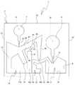
先ず、図1を参照して、検査装置100の構造を簡単に説明する。図1に示すように、検査装置100の上板102上には、回転する円盤状のターンテーブル103が設けられている。また、当該ターンテーブル103上には、ホルダ角度変更機構104が設けられている。ホルダ角度変更機構104には、検査対象受体1が挿入され固定されて、所定角度自転するホルダ107が一対設けられている。また、上板102の下方には、図示外のモータが設けられ、ターンテーブル103を回転駆動するようになっている。ターンテーブル103がその中心部分105を軸心として回転することにより各ホルダ107に各々挿入された検査対象受体1には、矢印A方向に遠心力が各々働くようになっている。また、ホルダ角度変更機構104の動作によりホルダ107が自転されて、検査対象受体1に働く遠心力の方向を変化させることができるようになっている。 First, the structure of the
ここで、図2の状態の検査対象受体1を初期状態という。図2では、重力方向は下方である。例えば、図5に示すように、検査対象受体1が初期状態から90度反時計回りに自転された状態で公転されると、検査対象受体1には図5に示す矢印A方向に重力よりも大きな力で遠心力が付与される。その遠心力により、検査対象受体1内に注入された検査対象の液体が移動する。 Here, the
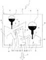
まず、検査対象受体1の構造について図2及び図3を参照して説明する。図2は、検査対象受体1を検査装置100に装着する場合の正面図であり、カバー部材3を取り去った状態の板状部材2の正面図を示している。図2及び図3に示すように、検査対象受体1は、所定の厚みを有する板状部材2から構成され、下端部22、上端部25、左端部23及び右端部24から構成される正面視長方形の板状の部材である。板状部材2の材質としては、一例として合成樹脂を用いることができる。 First, the structure of the
図2及び図3に示すように、検査対象受体1の板状部材2には、所定深さに掘り下げられた凹部からなる第一液溜め部5、当該第一液溜め部5から流出する液体を所定量受け分離する分離部14、第一液溜め部5から分離部14に液体を流す導入路20が設けられている。分離部14は、所定量計り取った液体を検査対象受体1に付加される遠心力により比重の小さい成分(以下、「分離成分」とも言う。)と、当該分離成分より比重の大きい成分(以下、「残留成分」とも言う。)とに分離する。また、検査対象受体1の板状部材2には、所定深さに掘り下げられた凹部からなり、分離部14で計り取った残りの余剰液体が流れる第六流路11、第六流路11の下流側に設けられ余剰液体が溜まる第一余剰部10が設けられている。 As shown in FIGS. 2 and 3, the plate-
また、板状部材2には、所定深さに掘り下げられた凹部からなり、分離部14で計量され分離された分離成分の液体が流れる第一流路40、第一流路40の下流側に接続された第四流路41、第四流路41の下流側に設けられ分離成分の液体を所定量計り取る計量部42及び計量部42で計り取った残りの余剰液体が溜まる第二余剰部43が設けられている。また、板状部材2には、計量部42が計り取った液体が流れる第五流路44と、第五流路44の下流側に設けられ、計量部42が計り取った液体が流れ込む受け部17とが設けられている。また、板状部材2には、所定深さに掘り下げられた凹部からなり、受け部17に注入する試薬や液体等が溜まる第二液溜め部6と、第二液溜め部6から受け部17に液体を流す導入路21とが形成されている。 Further, the plate-
また、分離部14の第一流路40側の側壁部141には、所定深さに掘り下げられた凹部からなり、分離部14で分離した残留成分が第一流路40へ流れ出すのを防止するためのトラップである保持部30が第二流路31により接続されている。 Further, the
また、図2及び図3に示すように、検査対象受体1には、その表面側に検査対象受体1の表面を覆うカバー部材3が貼り付けられている。このカバー部材3が第一液溜め部5、第二液溜め部6、分離部14、第一余剰部10、計量部42、第二余剰部43、受け部17、第一流路40、第二流路31、第六流路11、第四流路41、導入路20、及び導入路21等を封止する。カバー部材3は、正面視、板状部材2と同一形状の長方形の合成樹脂の透明の薄板から構成されている。また、カバー部材3には、第一液溜め部5に検査対象の液体や試薬等を注入する注入口15及び第二液溜め部6に試薬や液体等を注入する注入口16が形成されている。 Moreover, as shown in FIG.2 and FIG.3, the
以下、各部の構成の詳細を説明する。図2及び図3に示すように、第一液溜め部5は、注入口15から注入された検査対象の液体や試薬を溜める部分であり、板状部材2に対して、正面視円形に所定深さ掘り下げられている。また、第二液溜め部6は、注入口16から注入された検査対象の液体や試薬を溜める部分であり、板状部材2に対して、正面視円形に所定深さ掘り下げられている。 Details of the configuration of each unit will be described below. As shown in FIG. 2 and FIG. 3, the first
図2に於ける第一液溜め部5の下方には、分離部14が設けられている。分離部14は板状部材2に対して、所定深さ、所定幅及び所定長さを有する凹部であり、図2に示すように、底部側が検査対象受体1の次工程である受け部17方向に傾斜して延設されている。 A
図2に示すように、保持部30は正面視、矩形の凹部である。第二流路31の一端部が保持部30の上部に接続され、第二流路31の他端部が分離部14の側壁部141に接続されている。分離部14で分離した分離成分を次工程側の第一流路40に流す場合に、残留成分が第二流路31から保持部30に流れ込む。従って、残留成分が第一流路40に流れ込むことを防止できる。 As shown in FIG. 2, the holding
第六流路11は、板状部材2に形成された所定幅、所定深さ及び所定長さを有する凹部であり、図2に示すように第一余剰部10に向けて形成されている。また、第六流路11の下流側には、第一液溜め部5から流れ出し、分離部14で所定量計り取られた残りの液体が溜まる第一余剰部10が設けられている。第一余剰部10は、所定深さ、所定幅及び所定長さを有する凹部であり、検査対象受体1の下端部22と平行に延設される正面視長方形の凹部となっている。また、図2に示すように、第一余剰部10の奥部110は、分離部14の下方まで延設されている。 The
また、図2に示すように、第一流路40は、分離部14の上部の開口部から第二液溜め部6方向に向けて斜め右上方向に延設されている所定深さ、所定幅及び所定長さを有する凹部である。第一流路40の下流端部からは検査対象受体1の下端部22に向けて、所定深さ、所定幅及び所定長さを有する凹部である第四流路41が延設されている。第四流路41の下流側には、分離部14で分離された分離成分を所定量計り取る計量部42が形成されている。計量部42は正面視V字型に形成された所定深さ、所定幅及び所定長さを有する凹部である。計量部42の下流側(図2に於ける右端部24側)には、受け部17が形成されている。計量部42と受け部17とは第五流路44で接続されている。 In addition, as shown in FIG. 2, the
受け部17は、板状部材2に対して所定深さ掘り下げられた凹部である。この受け部17には、計量部42で所定量計り取られた分離成分が流入して、第二液溜め部6から流入する試薬や液体と混合される。また、図2に於ける計量部42の左側には、計量部42から溢れた余剰な分離成分が流入する第二余剰部43が形成されている。第二余剰部43は所定深さ掘り下げられた凹部であり、第二余剰部43の奥部143は、受け部17方向に延設されている。 The receiving
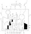
次に、図4から図11を参照して、上記検査対象受体1の使用方法について説明する。まず、図4に示すように、注入口15から検査対象の液体が第一液溜め部5に注入され、注入口16から試薬が第二液溜め部6に注入される。次いで、検査対象受体1は、左端部23及び右端部24を重力方向(矢印B方向)と平行にし、上端部25及び下端部22を重量方向と直交する状態で、図1に示す検査装置100のターンテーブル103のホルダ107に保持される。次いで、この状態から検査対象受体1が反時計回りに90度自転されると図5に示す状態になる。この時、検査対象受体1の左端部23及び右端部24が、図1に示す検査装置100のターンテーブル103の直径方向と平行になっている。 Next, with reference to FIG. 4 to FIG. 11, a method of using the
この状態で、検査対象受体1が検査装置100により公転されると、図5の矢印A方向に遠心力が働く。すると、第一液溜め部5に溜まっていた検査対象の液体70は、遠心力方向に流れ出し、分離部14に流れ込み、溢れた分は第六流路11を流れて第一余剰部10に入るが遠心力により、図5に示すように、検査対象受体1の下端部22側に引きつけられる。ここで、図5に示す分離部14の側壁部141と第二流路31の接続部から遠心力方向(矢印A方向)に伸ばした延長線と第二流路31の延設方向との成す角度θ1は90度以上になるようにする。これは、90度以上あれば、第一液溜め部5から分離部14に液体を流し込むときに、第二流路31に流れ込むことを防止できるからである。尚、角度θ1の最大値は、第二流路31が側壁部141に接続できる最大角度までである。 In this state, when the
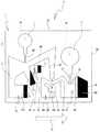
また、第二液溜め部6に溜まっていた試薬80は、遠心力方向に流れ出し、受け部17に流れ込む。ここで、図5に示すように、遠心力が矢印A方向に働いているので、受け部17内の試薬80は底部18側に引きつけられる。この状態で検査対象受体1が検査装置100により公転され続けると、分離部14に流れ込んだ検査対象の液体70が比重の異なる成分の混合液の場合には、図6に示すように、比重の小さい分離成分72と当該分離成分72より比重の大きい残留成分71とに遠心分離される。ここで、液体70の一例として血液を用いると、血漿(分離成分72)と血球(残留成分71)とに、ほぼ1対1の容積で分離される。従って、図6に示すように分離成分72と残留成分71との境界面Cが分離部14の中央部に出来る。ここで、分離部14の側壁部141と第二流路31の接続部は、境界面Cよりも遠心力方向の上流側になるように設けられている。この場合には、第二流路31の入り口が分離成分72側に位置するので、第二流路31の血球(残留成分71)による詰まりを防止することができる。 Further, the
次いで、図6に示す状態から、検査対象受体1が時計回りに90度自転されると図7に示す状態になる。この時、検査対象受体1の下端部22及び上端部25が、検査装置100のターンテーブル103の直径方向と平行になっている。この状態で、検査対象受体1が検査装置100により公転されると、図7の矢印A方向に遠心力が働く。すると、分離部14で分離された分離成分72(一例として血漿)は、遠心力の分力により分離部14の傾斜した側壁部141を登り第一流路40を流れ、第四流路41の右側に溜まる。残留成分71(一例として、血球)は、図7に示すように、分離部14にとどまる。尚、第一余剰部10の液体70は、奥部110側に溜まり、受け部17の試薬80は、受け部17の右壁19側に溜まる。ここで、図7に示すように、遠心力方向(矢印A方向)と第二流路31の延設方向が成す角度θ2は、当該遠心力方向と第一流路40の延設方向とが成す角度θ3より大きく構成されている。これにより、遠心力の付加された場合に、分離成分は第一流路40に流れ易く、分離成分が第二流路31に流れ込むことを防止できる。 Next, from the state shown in FIG. 6, when the
この状態で、検査対象受体1が検査装置100により公転されると、図8に示すように、分離部14の残留成分71(一例として、血球)は、第二流路31から保持部30に流れ込む。従って、分離部14の残留成分71が第一流路40に流れ込むことを防止できる。ここで、保持部30の容積は、残留成分71の容積を考慮し、溢れることの無い容積に形成されている。 In this state, when the
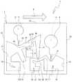
次いで、この状態から検査対象受体1が反時計回りに90度自転されると図9に示す状態になる。この時、検査対象受体1の左端部23及び右端部24が、図1に示す検査装置100のターンテーブル103の直径方向と平行になっている。この状態で、検査対象受体1が検査装置100により公転されると、図9の矢印A方向に遠心力が働く。すると、第四流路41に溜まっていた分離成分72(一例として血漿)は、計量部42に流れ込み、正面視三角形の凹部の容積だけ所定量が計り取られる。溢れた余剰の分離成分72は第二余剰部43に流れ込む。このとき、受け部17の試薬80は、受け部17の底部18側に溜まる。また、保持部30に溜まった残留成分71は、保持部30の内から逆流することなく保持される。 Next, when the
次いで、図9に示す状態から、検査対象受体1が時計回りに90度自転されると図10に示す状態になる。この時、検査対象受体1の下端部22及び上端部25が、検査装置100のターンテーブル103の直径方向と平行になっている。この状態で、検査対象受体1が検査装置100により公転されると、図10の矢印A方向に遠心力が働く。すると、計量部42で計量された分離成分72(一例として血漿)は、遠心力の分力により計量部42の傾斜した壁部を登り第五流路44から受け部17に流れ込む。このとき、第二余剰部43内の余剰の分離成分72は、第二余剰部43の奥部143に溜まり逆流しない。また、保持部30に溜まった残留成分71は、保持部30の内から逆流することなく保持される。 Next, from the state shown in FIG. 9, when the
次いで、図10に示す状態で、検査装置100のターンテーブル103の回転を止めると、図11に示すように、受け部17に流れ込んだ試薬80と計量部42から受け部17に流れ込んだ分離成分72とが混合され、混合液81となる。この状態で、第二余剰部43の底部には余剰の分離成分72が溜まり、第一余剰部10の底部には検査対象の液体70が溜まる。また、保持部30の底部には残留成分71が溜まり、分離部14の底部には残留成分71が溜まる。この後、受け部17で混合された混合液81に光をあてて調べる光学検査等の方法で測定する。尚、本第一実施の形態では、保持部30及び第二流路31を設けたので、次工程である第一流路40側に、残留成分71が流れ込み、受け部17で試薬80と混ざることを防止できる。 Next, when the rotation of the
(第二実施形態)
次に、図12を参照して、第二実施の形態について説明する。第二実施形態の検査対象受体1では、第一実施の形態と異なるのは、残留成分をトラップする保持部30が第一余剰部10と接続部32により接続されている点である。他の構造は、第一実施の形態の検査対象受体1と同じ構造である。この第二実施の形態では、保持部30を大きくする必要が無くスペースの確保が容易になる。また、第一余剰部10と保持部30とを一体に加工でき、加工が容易になる。また、残留成分をトラップする保持部30の容量を十分確保できる。(Second embodiment)
Next, a second embodiment will be described with reference to FIG. The
(第三実施形態)
次に、図13を参照して、第三実施の形態について説明する。第三実施形態の検査対象受体1では、第一実施の形態と異なるのは、残留成分をトラップする保持部30を分離部14に設けず、第一流路40の下流側に分離部14から流れ出た残留成分をトラップする所定深さの凹部である保持部50を設けた点である。他の構造は、第一実施の形態の検査対象受体1と同じ構造である。第三実施の形態の検査対象受体1では、第一流路40の底壁45の遠心力方向(矢印A方向)に対する傾斜角度を第一流路40の底壁46の遠心力方向(矢印A方向)に対する傾斜角度及び第一流路40の上壁47の遠心力方向(矢印A方向)に対する傾斜角度より小さくして、第一流路40の延設方向上に保持部50が開口している。従って、分離部14から第一流路40に残留成分が流れ出ても保持部50に確実にトラップすることができる。(Third embodiment)
Next, a third embodiment will be described with reference to FIG. In the
また、図13に示すように、分離部14で分離され取り出される分離成分の容積14A(ハッチング部)よりも保持部50の容積50A(ハッチング部)が小さくなるように構成されている。これにより、分離部14で分離され取り出される分離成分が全て保持部50にトラップされてしまうことを防止できる。 Further, as shown in FIG. 13, the
(第四実施形態)
次に、図14を参照して、第四実施の形態について説明する。第四実施形態の検査対象受体1では、第一実施の形態と異なるのは、残留成分をトラップする保持部30を分離部14に設けず、第一流路40の下流側に分離部14から流れ出た残留成分をトラップする保持部50と当該保持部50に正面視矩形の所定深さの凹部である第二保持部51を所定深さで所定幅かつ所定長さの凹部である第三流路52により接続した点である。この構成により、保持部50にトラップされた残留成分等は第三流路52から第二保持部51に流れ込むことができる。また、図14に示すように第三流路52は第二保持部51の上方に接続されているので、遠心力(矢印A)が付加されても、第二保持部51から残留成分が第三流路52を介して保持部50に逆流することがない。(Fourth embodiment)
Next, a fourth embodiment will be described with reference to FIG. In the
(第五実施形態)
次に、図15を参照して、第五実施の形態について説明する。第五実施形態の検査対象受体1では、第四実施の形態と異なるのは、保持部50に対する第三流路52の接続角度と、第三流路52の第二保持部51への接続位置である。即ち、第三流路52の延設方向と遠心力方向(矢印A方向)との成す角度θ4は、90度以下となっている。また、第三流路52は、第二保持部51の上部の遠心力方向(矢印A方向)と反対側(壁部151側)の端部に接続されている。従って、遠心力(矢印A)が付加されても、第二保持部51から残留成分が第三流路52を介して保持部50に逆流することがない。(Fifth embodiment)
Next, a fifth embodiment will be described with reference to FIG. In the
(第六実施形態)
次に、図16を参照して、第六実施の形態について説明する。第六実施形態の検査対象受体1では、第四実施の形態と異なるのは、保持部50に対する第三流路52の接続位置と、第二保持部51の延設方向である。即ち、第三流路52は、第二保持部51の上部の遠心力方向(矢印A方向)と反対側(壁部151側)の端部に接続されている。また、第二保持部51の奥部152は、第三流路52と第二保持部51が接する位置より、遠心力により分離部14から次工程へ分離成分を移行する状態時の遠心力方向(矢印A方向)に延設されている。従って、遠心力(矢印A)が付加されても、第二保持部51から残留成分が第三流路52を介して保持部50に逆流することがない。(Sixth embodiment)
Next, a sixth embodiment will be described with reference to FIG. In the
(第七実施形態)
次に、図17を参照して、第七実施の形態について説明する。第七実施形態の検査対象受体1では、第四実施の形態と異なるのは、残留成分を溜める第二保持部51が第一余剰部10と接続部153により接続されている点である。他の構造は、第四実施の形態の検査対象受体1と同じ構造である。この第七実施の形態では、第二保持部51を大きくする必要が無くスペースの確保が容易になる。また、第一余剰部10と第二保持部51とを一体に加工でき、加工が容易になる。また、残留成分をトラップする第二保持部51の容量を十分確保できる。(Seventh embodiment)
Next, a seventh embodiment will be described with reference to FIG. The
尚、上記の実施の形態は、分離部14が「分離部」の一例であり、カバー部材3が「蓋部」の一例である。他は、請求項の構成の名称と実施の形態の構成の名称は一致しているので、対応関係の説明は省略する。 In the above-described embodiment, the
尚、本発明は、上記実施形態に限られず、各種の変形ができる。例えば、検査対象受体1の材質は特に制限されず、ポリエチレンテレフタレート(PET)、ポリブチレンテレフタレート(PBT)、ポリメチルメタクリレート(PMMA)、ポリカーボネート(PC)、ポリスチレン(PS)、ポリプロピレン(PP)、ポリエチレン(PE)、ポリエチレンナフタレート(PEN)、ポリアリレート樹脂(PAR)、アクリロニトリル・ブタジエン・スチレン樹脂(ABS)、塩化ビニル樹脂(PVC)、ポリメチルペンテン樹脂(PMP)、ポリブタジエン樹脂(PBD)、生分解性ポリマー(BP)、シクロオレフィンポリマー(COP)、ポリジメチルシロキサン(PDMS)などの有機材料を用いることができる。また、シリコン、ガラス、石英等の無機材料を用いても良い。 The present invention is not limited to the above embodiment, and various modifications can be made. For example, the material of the
また、検査対象受体1では、液体の注入口は2つ設けているが、1つ、3つ、4つ等適宜設けても良い。また、検査対象の液体は、血液に限られず、比重の異なる成分が混合した液体であれば各種の液体を計量し、遠心分離して検査することができる。 In addition, in the
また、検査対象受体1では、分離部14に保持部30を設け、第一流路40に保持部50を設けても良い。また、分離部14に保持部30を設け、第一流路40に保持部50を設け、保持部50に第二保持部51を第三流路52により接続しても良い。 Further, in the
1 検査対象受体
2 板状部材
3 カバー部材
5 第一液溜め部
6 第二液溜め部
10 第一余剰部
11 第六流路
14 分離部
15 注入口
16 注入口
17 受け部
30 保持部
31 第二流路
40 第一流路
41 第四流路
42 計量部
43 第二余剰部
44 第五流路
50 保持部
51 第二保持部
52 第三流路
70 液体
71 残留成分
72 分離成分
100 検査装置
102 上板
103 ターンテーブル
104 ホルダ角度変更機構
105 中心部分
107 ホルダDESCRIPTION OF
103
Claims (13)
Translated fromJapanese前記流体回路は、少なくとも、遠心力により前記液体の成分を分離成分と当該分離成分より比重の大きい残留成分とに分離する分離部と、
前記分離部から次工程へ前記分離成分を導く第一流路と、
前記分離部で分離された前記分離成分が前記第一流路により前記分離部から前記次工程へ移行する際に前記分離部から流れ出る前記液体の一部を保持する保持部と、
前記分離部から前記保持部へ前記残留成分を導く第二流路と、を備え、
前記第二流路は前記分離部の前記第一流路側の側壁部に接続され、
前記側壁部は、前記分離部において前記分離成分と前記残留成分とに分離される際の遠心力の方向と、前記分離成分を前記第一流路を介して前記次工程へ導く際の遠心力の方向との間の方向に延設されていることを特徴とする検査対象受体。A test object receiver including at least a substrate having a liquid flow channel formed on a surface thereof and a lid portion covering the flow channel, and a fluid circuit including the flow channel and a back surface of the lid portion. Because
The fluid circuit includes at least a separation unit that separates the liquid component into a separated component and a residual component having a specific gravity greater than the separated component by centrifugal force;
A first flow path for guiding the separation component from the separation section to the next process;
A holding unit for holding a part of the liquid flowing out from the separation unit when the separation component separated in the separation unit is transferred from the separation unit to the next step by the first flow path;
A second flow path for guiding the residual component from the separation unit to the holding unit ,
The second channel is connected to the side wall of the separation unit on the first channel side,
The side wall portion has a centrifugal force direction when the separation component is separated into the separation component and the residual component in the separation portion, and a centrifugal force when the separation component is guided to the next step through the first flow path. A test object receptacle characterized by beingextended ina direction between the directions .
前記保持部と当該余剰部とが前記残留成分が流入可能に接続されていることを特徴とする請求項2に記載の検査対象受体。The surplus portion for storing the liquid overflowing from the separation unit at the time of introduction of the liquid fromthe liquid reservoir to the separator unit is provided,
The test object receptacle according to claim2 , wherein the holding part and the surplus part are connected to allow the residual component to flow in.
前記流体回路は、少なくとも、遠心力により前記液体の成分を分離成分と当該分離成分より比重の大きい残留成分とに分離する分離部と、
前記分離部から次工程へ前記分離成分を導く第一流路と、
前記分離部で分離された前記分離成分が前記第一流路により前記分離部から前記次工程へ移行する際に前記分離部から流れ出る前記液体の一部を保持する保持部と、
を備え、
前記保持部は前記第一流路の前記分離部に接続する壁面に設けられ、且つ、前記分離成分を前記第一流路を介して前記次工程へ導く際の遠心力の方向に対向して開口していることを特徴とする検査対象受体。A test object receiver including at least a substrate having a liquid flow channel formed on a surface thereof and a lid portion covering the flow channel, and a fluid circuit including the flow channel and a back surface of the lid portion. Because
The fluid circuit includes at least a separation unit that separates the liquid component into a separated component and a residual component having a specific gravity greater than the separated component by centrifugal force;
A first flow path for guiding the separation component from the separation section to the next process;
A holding unit for holding a part of the liquid flowing out from the separation unit when the separation component separated in the separation unit is transferred from the separation unit to the next step by the first flow path;
With
The holding portion is provided ona wall surface connected to the separation portion ofthe first flow path, and opens in opposition to a centrifugal force direction when the separation component is guided to the next process through the first flow path.it characterized in that it isinspection object receptacle.
前記保持部と当該第二保持部とを接続する第三流路とを備えたことを特徴とする請求項7に記載の検査対象受体。A second holding part for storing the residual component held in the holding part;
The test object receptacle according to claim 7, further comprising a third flow path connecting the holding part and the second holding part.
前記第二保持部と当該余剰部とが前記残留成分が流入可能に接続されていることを特徴とする請求項8に記載の検査対象受体。
Providing a surplus part for storing liquid overflowing from the separation part when the liquid is introduced into the separation part from a liquid storage part for storing a liquid to be inspected;
9. The inspection object receptacle according to claim 8, wherein the second holding part and the surplus part are connected so that the residual component can flow in.
Priority Applications (4)
| Application Number | Priority Date | Filing Date | Title |
|---|---|---|---|
| JP2011218510AJP5565398B2 (en) | 2011-09-30 | 2011-09-30 | Inspection target |
| EP12834966.9AEP2762888A4 (en) | 2011-09-30 | 2012-06-28 | TEST OBJECT ACCEPTOR |
| PCT/JP2012/066504WO2013046835A1 (en) | 2011-09-30 | 2012-06-28 | Test object acceptor |
| US14/224,521US9199235B2 (en) | 2011-09-30 | 2014-03-25 | Test chip |
Applications Claiming Priority (1)
| Application Number | Priority Date | Filing Date | Title |
|---|---|---|---|
| JP2011218510AJP5565398B2 (en) | 2011-09-30 | 2011-09-30 | Inspection target |
Publications (2)
| Publication Number | Publication Date |
|---|---|
| JP2013079812A JP2013079812A (en) | 2013-05-02 |
| JP5565398B2true JP5565398B2 (en) | 2014-08-06 |
Family
ID=47994895
Family Applications (1)
| Application Number | Title | Priority Date | Filing Date |
|---|---|---|---|
| JP2011218510AExpired - Fee RelatedJP5565398B2 (en) | 2011-09-30 | 2011-09-30 | Inspection target |
Country Status (4)
| Country | Link |
|---|---|
| US (1) | US9199235B2 (en) |
| EP (1) | EP2762888A4 (en) |
| JP (1) | JP5565398B2 (en) |
| WO (1) | WO2013046835A1 (en) |
Families Citing this family (12)
| Publication number | Priority date | Publication date | Assignee | Title |
|---|---|---|---|---|
| JP5958451B2 (en)* | 2013-11-29 | 2016-08-02 | ブラザー工業株式会社 | Inspection chip, liquid feeding method, and liquid feeding program |
| JP5915686B2 (en)* | 2014-03-31 | 2016-05-11 | ブラザー工業株式会社 | Inspection chip |
| JP2015197351A (en)* | 2014-03-31 | 2015-11-09 | ブラザー工業株式会社 | inspection chip |
| JP2015197352A (en)* | 2014-03-31 | 2015-11-09 | ブラザー工業株式会社 | Inspection chip |
| JP5910657B2 (en)* | 2014-03-31 | 2016-04-27 | ブラザー工業株式会社 | Inspection chip and inspection system |
| JP6588908B2 (en) | 2014-06-30 | 2019-10-09 | Phcホールディングス株式会社 | Sample analysis substrate, sample analysis apparatus, sample analysis system, and program for sample analysis system |
| WO2016002728A1 (en) | 2014-06-30 | 2016-01-07 | パナソニックヘルスケアホールディングス株式会社 | Substrate for sample analysis, sample analysis device, sample analysis system, and method for removing liquid from liquid that contains magnetic particles |
| US10539560B2 (en) | 2014-06-30 | 2020-01-21 | Phc Holdings Corporation | Substrate for sample analysis, and sample analysis apparatus |
| US10520521B2 (en) | 2014-06-30 | 2019-12-31 | Phc Holdings Corporation | Substrate for sample analysis, sample analysis device, sample analysis system, and program for sample analysis system |
| US10539583B2 (en) | 2014-12-12 | 2020-01-21 | Phc Holdings Corporation | Substrate for sample analysis, sample analysis device, sample analysis system, and program for sample analysis system |
| GB201620320D0 (en)* | 2016-11-30 | 2017-01-11 | Univ Dublin City | A fluidic device for aliquoting and combinatorial mixing of liquids |
| US20210001344A1 (en)* | 2019-07-03 | 2021-01-07 | Shimadzu Corporation | Sample holding disc for centrifugation |
Family Cites Families (15)
| Publication number | Priority date | Publication date | Assignee | Title |
|---|---|---|---|---|
| US5089417A (en) | 1987-07-01 | 1992-02-18 | Miles Inc. | Fluid separation and processing device |
| US4892708A (en) | 1987-07-01 | 1990-01-09 | Miles Inc. | Fluid separation and processing device |
| WO2006038682A1 (en)* | 2004-10-01 | 2006-04-13 | Kabushiki Kaisya Advance | Solid-liquid separation/measuring structure and method of solid-liquid separation/measuring |
| JP4973800B2 (en)* | 2005-08-19 | 2012-07-11 | パナソニック株式会社 | Analytical device and analytical apparatus using the same |
| KR101292536B1 (en)* | 2005-12-21 | 2013-08-07 | 삼성전자주식회사 | Bio memory disc and bio memory disc drive apparatus, and assay method using the same |
| JP2010503171A (en) | 2006-09-07 | 2010-01-28 | コーニンクレッカ フィリップス エレクトロニクス エヌ ヴィ | Lamp drive circuit and discharge lamp drive method |
| JP5254751B2 (en) | 2007-11-16 | 2013-08-07 | ローム株式会社 | Microchip |
| US8075853B2 (en) | 2007-11-16 | 2011-12-13 | Rohm Co., Ltd. | Microchip |
| JP5636629B2 (en)* | 2007-11-20 | 2014-12-10 | 東レ株式会社 | Liquid feeding chip and analysis method |
| WO2009096391A1 (en)* | 2008-01-28 | 2009-08-06 | Toray Industries, Inc. | Separating chip, and separating method |
| TWI385383B (en)* | 2008-05-28 | 2013-02-11 | Ind Tech Res Inst | Analytical system, and analytical method and flowing structure thereof |
| JP5298718B2 (en)* | 2008-09-12 | 2013-09-25 | セイコーエプソン株式会社 | Centrifugal device for filling biological sample reaction chip with reaction solution |
| EP2329276A4 (en)* | 2008-10-01 | 2012-07-04 | Samsung Electronics Co Ltd | CENTRIFUGAL MICROFLUIDIC APPARATUS, METHOD FOR MANUFACTURING SAME, AND METHOD FOR TESTING SAMPLES USING THE MICROFLUIDIC APPARATUS |
| JP2010145314A (en)* | 2008-12-22 | 2010-07-01 | Rohm Co Ltd | Microchip |
| TWI360438B (en)* | 2009-08-25 | 2012-03-21 | Ind Tech Res Inst | Analytical system, analytical method and flow-path |
- 2011
- 2011-09-30JPJP2011218510Apatent/JP5565398B2/ennot_activeExpired - Fee Related
- 2012
- 2012-06-28WOPCT/JP2012/066504patent/WO2013046835A1/enactiveApplication Filing
- 2012-06-28EPEP12834966.9Apatent/EP2762888A4/ennot_activeWithdrawn
- 2014
- 2014-03-25USUS14/224,521patent/US9199235B2/ennot_activeExpired - Fee Related
Also Published As
| Publication number | Publication date |
|---|---|
| US9199235B2 (en) | 2015-12-01 |
| WO2013046835A1 (en) | 2013-04-04 |
| EP2762888A4 (en) | 2015-06-17 |
| EP2762888A1 (en) | 2014-08-06 |
| US20140234184A1 (en) | 2014-08-21 |
| JP2013079812A (en) | 2013-05-02 |
Similar Documents
| Publication | Publication Date | Title |
|---|---|---|
| JP5565398B2 (en) | Inspection target | |
| RU2555049C2 (en) | Specimen processing cartridge and method of processing and/or analysis of specimen under action of centrifugal force | |
| CN102472739B (en) | Centrifugal microfluidic devices and the method for detecting the analysis thing from liquid sample | |
| CN102981004B (en) | Analytical device and analytical method using the analytical device | |
| US8075853B2 (en) | Microchip | |
| KR101930610B1 (en) | Rotatable cartridge for analyzing a biological sample | |
| WO2011001646A1 (en) | Magnetic particle transfer device and magnetic particle transfer method | |
| CN108020676A (en) | Hydraulic seal box body and liquid transporting method | |
| JP5359987B2 (en) | Inspection target | |
| JP2009300433A5 (en) | ||
| US8409447B2 (en) | Separation chip and separation method | |
| CN106489072A (en) | The rotating cylinder for analyzing biological sample with measuring room | |
| JP4391790B2 (en) | Chip usage and inspection chip | |
| JP5359964B2 (en) | Inspection object receiver, inspection apparatus and inspection method | |
| JP2012078115A (en) | Inspection object acceptor | |
| JP5736230B2 (en) | Microchip | |
| US20060204403A1 (en) | Micro-fluidic fluid separation device and method | |
| JP2012078094A (en) | Inspection object acceptor | |
| US20200230600A1 (en) | Apparatus and methods for handling liquid | |
| JP5408094B2 (en) | Inspection target | |
| JP2009276143A (en) | Microchip | |
| JP2012078102A (en) | Inspection object acceptor | |
| JP2009156683A (en) | Microchip | |
| JP4815368B2 (en) | Hemagglutination determination container | |
| JP2014134393A (en) | Microchip |
Legal Events
| Date | Code | Title | Description |
|---|---|---|---|
| A131 | Notification of reasons for refusal | Free format text:JAPANESE INTERMEDIATE CODE: A131 Effective date:20140114 | |
| A521 | Written amendment | Free format text:JAPANESE INTERMEDIATE CODE: A523 Effective date:20140317 | |
| TRDD | Decision of grant or rejection written | ||
| A01 | Written decision to grant a patent or to grant a registration (utility model) | Free format text:JAPANESE INTERMEDIATE CODE: A01 Effective date:20140520 | |
| A61 | First payment of annual fees (during grant procedure) | Free format text:JAPANESE INTERMEDIATE CODE: A61 Effective date:20140602 | |
| R150 | Certificate of patent or registration of utility model | Ref document number:5565398 Country of ref document:JP Free format text:JAPANESE INTERMEDIATE CODE: R150 | |
| LAPS | Cancellation because of no payment of annual fees |