JP5562598B2 - Image display apparatus, image display method, and magnetic resonance imaging apparatus - Google Patents
Image display apparatus, image display method, and magnetic resonance imaging apparatusDownload PDFInfo
- Publication number
- JP5562598B2 JP5562598B2JP2009208519AJP2009208519AJP5562598B2JP 5562598 B2JP5562598 B2JP 5562598B2JP 2009208519 AJP2009208519 AJP 2009208519AJP 2009208519 AJP2009208519 AJP 2009208519AJP 5562598 B2JP5562598 B2JP 5562598B2
- Authority
- JP
- Japan
- Prior art keywords
- image
- images
- region
- unit
- display
- Prior art date
- Legal status (The legal status is an assumption and is not a legal conclusion. Google has not performed a legal analysis and makes no representation as to the accuracy of the status listed.)
- Active
Links
Images


Classifications
- A—HUMAN NECESSITIES
- A61—MEDICAL OR VETERINARY SCIENCE; HYGIENE
- A61B—DIAGNOSIS; SURGERY; IDENTIFICATION
- A61B5/00—Measuring for diagnostic purposes; Identification of persons
- A61B5/05—Detecting, measuring or recording for diagnosis by means of electric currents or magnetic fields; Measuring using microwaves or radio waves
- A61B5/055—Detecting, measuring or recording for diagnosis by means of electric currents or magnetic fields; Measuring using microwaves or radio waves involving electronic [EMR] or nuclear [NMR] magnetic resonance, e.g. magnetic resonance imaging
- A—HUMAN NECESSITIES
- A61—MEDICAL OR VETERINARY SCIENCE; HYGIENE
- A61B—DIAGNOSIS; SURGERY; IDENTIFICATION
- A61B5/00—Measuring for diagnostic purposes; Identification of persons
- A61B5/40—Detecting, measuring or recording for evaluating the nervous system
- A61B5/4058—Detecting, measuring or recording for evaluating the nervous system for evaluating the central nervous system
- A61B5/4064—Evaluating the brain
- A—HUMAN NECESSITIES
- A61—MEDICAL OR VETERINARY SCIENCE; HYGIENE
- A61B—DIAGNOSIS; SURGERY; IDENTIFICATION
- A61B6/00—Apparatus or devices for radiation diagnosis; Apparatus or devices for radiation diagnosis combined with radiation therapy equipment
- A61B6/02—Arrangements for diagnosis sequentially in different planes; Stereoscopic radiation diagnosis
- A61B6/03—Computed tomography [CT]
- A61B6/032—Transmission computed tomography [CT]
- A—HUMAN NECESSITIES
- A61—MEDICAL OR VETERINARY SCIENCE; HYGIENE
- A61B—DIAGNOSIS; SURGERY; IDENTIFICATION
- A61B6/00—Apparatus or devices for radiation diagnosis; Apparatus or devices for radiation diagnosis combined with radiation therapy equipment
- A61B6/46—Arrangements for interfacing with the operator or the patient
- A61B6/461—Displaying means of special interest
- A61B6/463—Displaying means of special interest characterised by displaying multiple images or images and diagnostic data on one display
- A—HUMAN NECESSITIES
- A61—MEDICAL OR VETERINARY SCIENCE; HYGIENE
- A61B—DIAGNOSIS; SURGERY; IDENTIFICATION
- A61B6/00—Apparatus or devices for radiation diagnosis; Apparatus or devices for radiation diagnosis combined with radiation therapy equipment
- A61B6/46—Arrangements for interfacing with the operator or the patient
- A61B6/467—Arrangements for interfacing with the operator or the patient characterised by special input means
- A61B6/469—Arrangements for interfacing with the operator or the patient characterised by special input means for selecting a region of interest [ROI]
- G—PHYSICS
- G01—MEASURING; TESTING
- G01R—MEASURING ELECTRIC VARIABLES; MEASURING MAGNETIC VARIABLES
- G01R33/00—Arrangements or instruments for measuring magnetic variables
- G01R33/20—Arrangements or instruments for measuring magnetic variables involving magnetic resonance
- G01R33/44—Arrangements or instruments for measuring magnetic variables involving magnetic resonance using nuclear magnetic resonance [NMR]
- G01R33/48—NMR imaging systems
- G01R33/483—NMR imaging systems with selection of signals or spectra from particular regions of the volume, e.g. in vivo spectroscopy
- G—PHYSICS
- G01—MEASURING; TESTING
- G01R—MEASURING ELECTRIC VARIABLES; MEASURING MAGNETIC VARIABLES
- G01R33/00—Arrangements or instruments for measuring magnetic variables
- G01R33/20—Arrangements or instruments for measuring magnetic variables involving magnetic resonance
- G01R33/44—Arrangements or instruments for measuring magnetic variables involving magnetic resonance using nuclear magnetic resonance [NMR]
- G01R33/48—NMR imaging systems
- G01R33/54—Signal processing systems, e.g. using pulse sequences ; Generation or control of pulse sequences; Operator console
- G01R33/56—Image enhancement or correction, e.g. subtraction or averaging techniques, e.g. improvement of signal-to-noise ratio and resolution
- G01R33/563—Image enhancement or correction, e.g. subtraction or averaging techniques, e.g. improvement of signal-to-noise ratio and resolution of moving material, e.g. flow contrast angiography
- G01R33/56366—Perfusion imaging
- G—PHYSICS
- G06—COMPUTING OR CALCULATING; COUNTING
- G06T—IMAGE DATA PROCESSING OR GENERATION, IN GENERAL
- G06T7/00—Image analysis
- G06T7/0002—Inspection of images, e.g. flaw detection
- G06T7/0012—Biomedical image inspection
- G—PHYSICS
- G06—COMPUTING OR CALCULATING; COUNTING
- G06T—IMAGE DATA PROCESSING OR GENERATION, IN GENERAL
- G06T7/00—Image analysis
- G06T7/30—Determination of transform parameters for the alignment of images, i.e. image registration
- G—PHYSICS
- G06—COMPUTING OR CALCULATING; COUNTING
- G06T—IMAGE DATA PROCESSING OR GENERATION, IN GENERAL
- G06T9/00—Image coding
- G06T9/20—Contour coding, e.g. using detection of edges
- A—HUMAN NECESSITIES
- A61—MEDICAL OR VETERINARY SCIENCE; HYGIENE
- A61B—DIAGNOSIS; SURGERY; IDENTIFICATION
- A61B5/00—Measuring for diagnostic purposes; Identification of persons
- A61B5/74—Details of notification to user or communication with user or patient; User input means
- A61B5/742—Details of notification to user or communication with user or patient; User input means using visual displays
- A61B5/7425—Displaying combinations of multiple images regardless of image source, e.g. displaying a reference anatomical image with a live image
- A—HUMAN NECESSITIES
- A61—MEDICAL OR VETERINARY SCIENCE; HYGIENE
- A61B—DIAGNOSIS; SURGERY; IDENTIFICATION
- A61B6/00—Apparatus or devices for radiation diagnosis; Apparatus or devices for radiation diagnosis combined with radiation therapy equipment
- A61B6/48—Diagnostic techniques
- A61B6/481—Diagnostic techniques involving the use of contrast agents
- A—HUMAN NECESSITIES
- A61—MEDICAL OR VETERINARY SCIENCE; HYGIENE
- A61B—DIAGNOSIS; SURGERY; IDENTIFICATION
- A61B6/00—Apparatus or devices for radiation diagnosis; Apparatus or devices for radiation diagnosis combined with radiation therapy equipment
- A61B6/50—Apparatus or devices for radiation diagnosis; Apparatus or devices for radiation diagnosis combined with radiation therapy equipment specially adapted for specific body parts; specially adapted for specific clinical applications
- A61B6/507—Apparatus or devices for radiation diagnosis; Apparatus or devices for radiation diagnosis combined with radiation therapy equipment specially adapted for specific body parts; specially adapted for specific clinical applications for determination of haemodynamic parameters, e.g. perfusion CT
- A—HUMAN NECESSITIES
- A61—MEDICAL OR VETERINARY SCIENCE; HYGIENE
- A61B—DIAGNOSIS; SURGERY; IDENTIFICATION
- A61B8/00—Diagnosis using ultrasonic, sonic or infrasonic waves
- A61B8/08—Clinical applications
- A61B8/0808—Clinical applications for diagnosis of the brain
- G—PHYSICS
- G01—MEASURING; TESTING
- G01R—MEASURING ELECTRIC VARIABLES; MEASURING MAGNETIC VARIABLES
- G01R33/00—Arrangements or instruments for measuring magnetic variables
- G01R33/20—Arrangements or instruments for measuring magnetic variables involving magnetic resonance
- G—PHYSICS
- G01—MEASURING; TESTING
- G01R—MEASURING ELECTRIC VARIABLES; MEASURING MAGNETIC VARIABLES
- G01R33/00—Arrangements or instruments for measuring magnetic variables
- G01R33/20—Arrangements or instruments for measuring magnetic variables involving magnetic resonance
- G01R33/28—Details of apparatus provided for in groups G01R33/44 - G01R33/64
- G01R33/285—Invasive instruments, e.g. catheters or biopsy needles, specially adapted for tracking, guiding or visualization by NMR
- G—PHYSICS
- G01—MEASURING; TESTING
- G01R—MEASURING ELECTRIC VARIABLES; MEASURING MAGNETIC VARIABLES
- G01R33/00—Arrangements or instruments for measuring magnetic variables
- G01R33/20—Arrangements or instruments for measuring magnetic variables involving magnetic resonance
- G01R33/44—Arrangements or instruments for measuring magnetic variables involving magnetic resonance using nuclear magnetic resonance [NMR]
- G01R33/48—NMR imaging systems
- G01R33/4806—Functional imaging of brain activation
- G—PHYSICS
- G01—MEASURING; TESTING
- G01R—MEASURING ELECTRIC VARIABLES; MEASURING MAGNETIC VARIABLES
- G01R33/00—Arrangements or instruments for measuring magnetic variables
- G01R33/20—Arrangements or instruments for measuring magnetic variables involving magnetic resonance
- G01R33/44—Arrangements or instruments for measuring magnetic variables involving magnetic resonance using nuclear magnetic resonance [NMR]
- G01R33/48—NMR imaging systems
- G01R33/54—Signal processing systems, e.g. using pulse sequences ; Generation or control of pulse sequences; Operator console
- G01R33/56—Image enhancement or correction, e.g. subtraction or averaging techniques, e.g. improvement of signal-to-noise ratio and resolution
- G01R33/5602—Image enhancement or correction, e.g. subtraction or averaging techniques, e.g. improvement of signal-to-noise ratio and resolution by filtering or weighting based on different relaxation times within the sample, e.g. T1 weighting using an inversion pulse
- G—PHYSICS
- G01—MEASURING; TESTING
- G01R—MEASURING ELECTRIC VARIABLES; MEASURING MAGNETIC VARIABLES
- G01R33/00—Arrangements or instruments for measuring magnetic variables
- G01R33/20—Arrangements or instruments for measuring magnetic variables involving magnetic resonance
- G01R33/44—Arrangements or instruments for measuring magnetic variables involving magnetic resonance using nuclear magnetic resonance [NMR]
- G01R33/48—NMR imaging systems
- G01R33/54—Signal processing systems, e.g. using pulse sequences ; Generation or control of pulse sequences; Operator console
- G01R33/56—Image enhancement or correction, e.g. subtraction or averaging techniques, e.g. improvement of signal-to-noise ratio and resolution
- G01R33/5608—Data processing and visualization specially adapted for MR, e.g. for feature analysis and pattern recognition on the basis of measured MR data, segmentation of measured MR data, edge contour detection on the basis of measured MR data, for enhancing measured MR data in terms of signal-to-noise ratio by means of noise filtering or apodization, for enhancing measured MR data in terms of resolution by means for deblurring, windowing, zero filling, or generation of gray-scaled images, colour-coded images or images displaying vectors instead of pixels
- G—PHYSICS
- G01—MEASURING; TESTING
- G01R—MEASURING ELECTRIC VARIABLES; MEASURING MAGNETIC VARIABLES
- G01R33/00—Arrangements or instruments for measuring magnetic variables
- G01R33/20—Arrangements or instruments for measuring magnetic variables involving magnetic resonance
- G01R33/44—Arrangements or instruments for measuring magnetic variables involving magnetic resonance using nuclear magnetic resonance [NMR]
- G01R33/48—NMR imaging systems
- G01R33/54—Signal processing systems, e.g. using pulse sequences ; Generation or control of pulse sequences; Operator console
- G01R33/56—Image enhancement or correction, e.g. subtraction or averaging techniques, e.g. improvement of signal-to-noise ratio and resolution
- G01R33/563—Image enhancement or correction, e.g. subtraction or averaging techniques, e.g. improvement of signal-to-noise ratio and resolution of moving material, e.g. flow contrast angiography
- G01R33/56341—Diffusion imaging
- G—PHYSICS
- G01—MEASURING; TESTING
- G01R—MEASURING ELECTRIC VARIABLES; MEASURING MAGNETIC VARIABLES
- G01R33/00—Arrangements or instruments for measuring magnetic variables
- G01R33/20—Arrangements or instruments for measuring magnetic variables involving magnetic resonance
- G01R33/44—Arrangements or instruments for measuring magnetic variables involving magnetic resonance using nuclear magnetic resonance [NMR]
- G01R33/48—NMR imaging systems
- G01R33/54—Signal processing systems, e.g. using pulse sequences ; Generation or control of pulse sequences; Operator console
- G01R33/56—Image enhancement or correction, e.g. subtraction or averaging techniques, e.g. improvement of signal-to-noise ratio and resolution
- G01R33/563—Image enhancement or correction, e.g. subtraction or averaging techniques, e.g. improvement of signal-to-noise ratio and resolution of moving material, e.g. flow contrast angiography
- G01R33/5635—Angiography, e.g. contrast-enhanced angiography [CE-MRA] or time-of-flight angiography [TOF-MRA]
Landscapes
- Health & Medical Sciences (AREA)
- Engineering & Computer Science (AREA)
- Physics & Mathematics (AREA)
- Life Sciences & Earth Sciences (AREA)
- Nuclear Medicine, Radiotherapy & Molecular Imaging (AREA)
- Medical Informatics (AREA)
- General Health & Medical Sciences (AREA)
- Radiology & Medical Imaging (AREA)
- High Energy & Nuclear Physics (AREA)
- General Physics & Mathematics (AREA)
- Biomedical Technology (AREA)
- Animal Behavior & Ethology (AREA)
- Veterinary Medicine (AREA)
- Public Health (AREA)
- Surgery (AREA)
- Molecular Biology (AREA)
- Biophysics (AREA)
- Pathology (AREA)
- Heart & Thoracic Surgery (AREA)
- Optics & Photonics (AREA)
- Theoretical Computer Science (AREA)
- Condensed Matter Physics & Semiconductors (AREA)
- Neurology (AREA)
- Signal Processing (AREA)
- Human Computer Interaction (AREA)
- Computer Vision & Pattern Recognition (AREA)
- Pulmonology (AREA)
- Vascular Medicine (AREA)
- Psychology (AREA)
- Quality & Reliability (AREA)
- Multimedia (AREA)
- Physiology (AREA)
- Spectroscopy & Molecular Physics (AREA)
- Neurosurgery (AREA)
- Magnetic Resonance Imaging Apparatus (AREA)
- Measuring And Recording Apparatus For Diagnosis (AREA)
- Apparatus For Radiation Diagnosis (AREA)
Description
Translated fromJapanese本発明は、画像表示装置、画像表示方法および磁気共鳴イメージング装置に関し、特に、画像間での視点の移動をともなうことなく、撮像手法の違いによる細部の変化を容易に観察することができる画像表示装置、画像表示方法および磁気共鳴イメージング装置に関する。 The present invention relates to an image display device, an image display method, and a magnetic resonance imaging apparatus, and in particular, an image display that can easily observe a change in details due to a difference in imaging method without moving a viewpoint between images. The present invention relates to an apparatus, an image display method, and a magnetic resonance imaging apparatus.
従来、医療の現場では、各種の画像診断装置を用いて撮像された各種の画像を用いて、さまざまな診断や治療が行われている。例えば、磁気共鳴イメージング(MRI:Magnetic Resonance Imaging)装置を用いた場合、縦緩和強調画像(T1W画像)や横緩和強調画像(T2W画像)、プロトン密度画像、Flair画像、脂肪抑制画像、Diffusion画像、Perfusion画像、f−MRI画像、MRスペクトロスコピー(MRS:MR Spectroscopy)など、枚挙にいとまがないほどの多様な画像を撮像することができる。また、X線コンピュータ断層撮影装置(X線CT(Computed Tomography)装置)を用いた場合でも、通常のCT値の解剖画像のみならず、血流などの機能画像を撮像することができる。Conventionally, in the medical field, various diagnoses and treatments have been performed using various images captured using various image diagnostic apparatuses. For example, when a magnetic resonance imaging (MRI) apparatus is used, a longitudinal relaxation enhanced image (T1 W image), a lateral relaxation enhanced image (T2 W image), a proton density image, a Flair image, and a fat suppression image A variety of images such as diffusion images, perfusion images, f-MRI images, MR spectroscopy (MRS) can be taken. Even when an X-ray computed tomography apparatus (X-ray CT (Computed Tomography) apparatus) is used, not only an anatomical image having a normal CT value but also a functional image such as a blood flow can be captured.
そして、通常、複数の異なる画像を読影する場合には、シャーカステンにフィルムを並べたりモニター上で画像を並べたりして、それぞれの画像の間で同一解剖部位に相当する箇所に視線を移動させながら診断が行われている。このような診断では、並べられた数種類の画像間でそれぞれの関心領域に視点を移動させながら読影するため、読影に時間を要する。また、各画像の解剖学的な細部を比較しながらの診断は、視線移動がともなうため非常に困難であった。 Usually, when interpreting a plurality of different images, films are arranged on the schacus ten or images are arranged on the monitor, and the line of sight is moved to a position corresponding to the same anatomical site between the images. A diagnosis has been made. In such a diagnosis, since the interpretation is performed while moving the viewpoint to each region of interest between several types of images arranged, it takes time to interpret. In addition, the diagnosis while comparing the anatomical details of each image is very difficult because the eye movement is accompanied.
そこで、例えば、超音波診断装置等では、フュージョン法と呼ばれる、同一部位が撮像されたモノクロ画像とカラー画像とを重ねて表示する方法が用いられている。また、同一部位を撮像した複数の画像がある場合に、それらの画像を一枚ずつ次々と切り替えながら画面上の略同一位置に表示することによって、視線移動をともなわない比較読影を可能にする方法も考案されている(例えば、特許文献1参照)。 Therefore, for example, an ultrasonic diagnostic apparatus or the like uses a method called a fusion method, in which a monochrome image obtained by imaging the same part and a color image are displayed in an overlapping manner. In addition, when there are a plurality of images obtained by imaging the same part, a method of enabling comparative interpretation without moving the line of sight by displaying the images at substantially the same position on the screen while switching one by one. Has also been devised (see, for example, Patent Document 1).
しかしながら、従来の技術では、撮像手法の違いによる細部の変化を容易に観察することが困難であった。例えば、フュージョン法による表示では、少なくとも2つの画像を重ねるため、重ねられる画像の一方はモノクロ画像などの空間分解能が小さいものや局所性があるものに限られてしまう。また、画像を略同一位置で切り替えながら表示する方法では、視点移動を少なくすることは考慮されているものの、撮像手法の違いによる細部の変化を観察することは考慮されていない。 However, with the conventional technology, it has been difficult to easily observe changes in details due to differences in imaging methods. For example, in the display by the fusion method, since at least two images are superimposed, one of the images to be superimposed is limited to one having a small spatial resolution such as a monochrome image or having locality. Further, in the method of displaying images while switching at substantially the same position, it is considered that the movement of the viewpoint is reduced, but it is not considered that the change in detail due to the difference in the imaging method is observed.
本発明は、上述した従来技術による課題を解決するためになされたものであり、画像間での視点の移動をともなうことなく、撮像手法の違いによる細部の変化を容易に観察することができる画像表示装置、画像表示方法および磁気共鳴イメージング装置を提供することを目的とする。 The present invention has been made to solve the above-described problems caused by the prior art, and can easily observe changes in details due to differences in imaging methods without moving the viewpoint between images. An object is to provide a display device, an image display method, and a magnetic resonance imaging apparatus.
本発明の一態様にかかる画像表示装置は、画像診断装置によって撮像された被検体の同一部位を含む種類の異なる複数の画像それぞれについて、各画像に含まれる同一部位に共通して関心領域を設定する関心領域設定部と、前記複数の画像それぞれについて、前記関心領域設定部によって設定された前記関心領域に含まれる画素の画素値をもとに特徴解析を行う特徴解析部と、表示部が有する表示領域の略同一位置に前記複数の画像を所定の順序で切り替えながら表示させるとともに、前記複数の画像の表示の切り替えに連動して、前記特徴解析部によって画像ごとに得られた複数の前記特徴解析の結果を前記表示領域の略同一位置に切り替えながら表示させる表示制御部と、を備える。The image display apparatus according to an aspect of the present invention,with the respective pluralityof different kinds of images including the same region of the subject taken by the imagingdevice, a region of interestin common to the same site contained in each image A region-of-interest setting unit to be set, a feature analysis unit that performs feature analysis on each of the plurality of images based on pixel values of pixels included in the region of interest set by the region-of-interest setting unit, and a display unit It causes the plurality of images in substantially the same position of the display area is displayed by switching in a predetermined order with,in conjunction with the switching of the display of the plurality of images,a plurality of obtained per Therefore image on the feature analyzing unit And a display control unit that displays the result of the feature analysiswhile switching to substantially the same position in the display area .
また、本発明の他の態様にかかる画像表示装置は、画像診断装置によって撮像された被検体の同一部位を含む種類の異なる複数の画像それぞれについて、所定の領域抽出処理を行うことによってセグメンテーション領域を抽出する関心領域設定部と、前記複数の画像それぞれについて、前記関心領域設定部によって抽出されたセグメンテーション領域の境界を抽出する特徴解析を行う特徴解析部と、表示部が有する表示領域の略同一位置に前記複数の画像を所定の順序で切り替えながら表示させるとともに、前記複数の画像の表示の切り替えに連動して、前記特徴解析部によって画像ごとに抽出された複数のセグメンテーション領域の境界を同時に各画像に重畳して表示させる表示制御部と、を備える。また、本発明の他の態様にかかる画像表示装置は、画像診断装置によって時系列に撮像された被検体の同一部位を含む時相の異なる複数の画像それぞれに関心領域を設定する関心領域設定部と、前記関心領域設定部によって前記複数の画像それぞれに設定された前記関心領域に含まれる画素の画素値をもとにTDC(Time Density Curve)を算出する特徴解析を行う特徴解析部と、表示部が有する表示領域の略同一位置に前記複数の画像を所定の順序で切り替えながら表示させるとともに、前記特徴解析部によって算出されたTDCを表示させ、さらに、前記複数の画像の表示の切り替えに連動して、前記関心領域設定部によって設定された関心領域と前記TDCとの対応を示す情報を各画像に重畳して表示させる表示制御部と、を備える。The image display device according to another aspect of the present inventionperforms a predetermined region extraction process on each of a plurality of different types of images including the same part of the subject imaged by the image diagnostic device, thereby obtaining a segmentation region. A region-of-interest setting unit to be extracted, a feature analysis unit that performs a feature analysis that extracts a boundary of the segmentation region extracted by the region-of-interest setting unit for each of the plurality of images, and substantially the same position of the display region that the display unit has The plurality of images are displayed while being switched in a predetermined order, and at the same time, the boundaries of the plurality of segmentation regions extracted for each image by the feature analysis unit are simultaneously linked to the switching of the display of the plurality of images. And a display control unit that displays the image superimposed on the display .In addition, an image display device according to another aspect of the present invention includes a region-of-interest setting unit that sets a region of interest in each of a plurality of images having different time phases including the same part of the subject imaged in time series by the image diagnostic device. A feature analysis unit that performs a feature analysis that calculates a TDC (Time Density Curve) based on pixel values of pixels included in the region of interest set in each of the plurality of images by the region of interest setting unit, and a display The plurality of images are displayed while switching in a predetermined order at substantially the same position in the display area of the unit, and the TDC calculated by the feature analysis unit is displayed, and further linked to the switching of the display of the plurality of images. And a display control unit that superimposes and displays information indicating the correspondence between the region of interest set by the region of interest setting unit and the TDC on each image.
また、本発明の他の態様にかかる画像表示方法は、画像診断装置によって撮像された被検体の同一部位を含む種類の異なる複数の画像それぞれについて、各画像に含まれる同一部位に共通して関心領域を設定し、前記複数の画像それぞれについて、前記関心領域に含まれる画素の画素値をもとに特徴解析を行い、表示部が有する表示領域の略同一位置に前記複数の画像を所定の順序で切り替えながら表示させるとともに、前記複数の画像の表示の切り替えに連動して、画像ごとに得られた複数の前記特徴解析の結果を前記表示領域の略同一位置に切り替えながら表示させる、ことを含む。The image display method according to another aspect of the present invention,with the respective pluralityof different kinds of images including the same region of the subject taken by the image diagnosticapparatus, in common with the same site contained in each image A region of interest is set, and for each of the plurality of images, feature analysis is performed based on pixel values of pixels included in the region of interest, and the plurality of images are set at substantially the same position in the display region of the display unit. The display is performed while switching in order,and the plurality of feature analysis resultsobtained for each image aredisplayed while being switched to substantially the same position in the display areain conjunction with the switching of the display of the plurality of images. Including.
また、本発明の他の態様にかかる画像表示方法は、画像診断装置によって撮像された被検体の同一部位を含む種類の異なる複数の画像それぞれについて、所定の領域抽出処理を行うことによってセグメンテーション領域を抽出し、前記複数の画像それぞれについて、前記セグメンテーション領域の境界を抽出する特徴解析を行い、表示部が有する表示領域の略同一位置に前記複数の画像を所定の順序で切り替えながら表示させるとともに、前記複数の画像の表示の切り替えに連動して、画像ごとに抽出された複数のセグメンテーション領域の境界を同時に各画像に重畳して表示させる、ことを含む。また、本発明の他の態様にかかる画像表示方法は、画像診断装置によって時系列に撮像された被検体の同一部位を含む時相の異なる複数の画像それぞれに関心領域を設定し、前記複数の画像それぞれに設定された前記関心領域に含まれる画素の画素値をもとにTDC(Time Density Curve)を算出する特徴解析を行い、表示部が有する表示領域の略同一位置に前記複数の画像を所定の順序で切り替えながら表示させるとともに、前記TDCを表示させ、さらに、前記複数の画像の表示の切り替えに連動して、前記関心領域と前記TDCとの対応を示す情報を各画像に重畳して表示させる、ことを含む。In addition, an image display method according to another aspect of the present inventionprovides a segmentation region by performing a predetermined region extraction process on each of a plurality of different types of images including the same part of a subject imaged by animage diagnostic apparatus. Extracting, performing a feature analysis for extracting a boundary of the segmentation region for each of the plurality of images, displaying the plurality of images while switching in a predetermined order at substantially the same position in the display region of the display unit, and In conjunction with the switching of the display of the plurality of images, the boundaries of the plurality of segmentation regions extracted for each image are simultaneously superimposed on each image and displayed .The image display method according to another aspect of the present invention sets a region of interest in each of a plurality of images having different time phases including the same part of the subject imaged in time series by the image diagnostic apparatus, A feature analysis is performed to calculate a TDC (Time Density Curve) based on pixel values of pixels included in the region of interest set for each image, and the plurality of images are placed at substantially the same position in the display region of the display unit. In addition to displaying the TDC while switching in a predetermined order, the information indicating the correspondence between the region of interest and the TDC is superimposed on each image in conjunction with the display switching of the plurality of images. Including displaying.
また、本発明の他の態様にかかる磁気共鳴イメージング装置は、被検体の同一部位を含む種類の異なる複数の画像を撮像する撮像部と、前記撮像部によって撮像された前記複数の画像それぞれについて、各画像に含まれる同一部位に共通して関心領域を設定する関心領域設定部と、前記複数の画像それぞれについて、前記関心領域設定部によって設定された前記関心領域に含まれる画素の画素値をもとに特徴解析を行う特徴解析部と、表示部が有する表示領域の略同一位置に前記複数の画像を所定の順序で切り替えながら表示させるとともに、前記複数の画像の表示の切り替えに連動して、前記特徴解析部によって画像ごとに得られた複数の前記特徴解析の結果を前記表示領域の略同一位置に切り替えながら表示させる表示制御部と、を備える。The magnetic resonance imaging apparatus according to another aspect of the present invention includes an imaging unit for imaging a pluralityof different kinds of images including the same region of the object,with each of the plurality of images captured by the imaging unitA region-of-interest setting unit that sets a region of interestin common to the same part included in each image, and a pixel value of a pixel included in the region of interest set by the region-of-interest setting unit for each of the plurality of images The feature analysis unit that performs the feature analysis and the plurality of images are displayed while switching in a predetermined order at substantially the same position in the display area of the display unit,and in conjunction with the switching of the display of the plurality of images , and a display control unit for displayingwhile switching results ofa plurality of the feature analysisobtained for each result image to the feature analysis unitat substantially the same position of the display region .
また、本発明の他の態様にかかる磁気共鳴イメージング装置は、被検体の同一部位を含む種類の異なる複数の画像を撮像する撮像部と、前記撮像部によって撮像された前記複数の画像それぞれについて、所定の領域抽出処理を行うことによってセグメンテーション領域を抽出する関心領域設定部と、前記複数の画像それぞれについて、前記関心領域設定部によって抽出されたセグメンテーション領域の境界を抽出する特徴解析を行う特徴解析部と、表示部が有する表示領域の略同一位置に前記複数の画像を所定の順序で切り替えながら表示させるとともに、前記複数の画像の表示の切り替えに連動して、前記特徴解析部によって画像ごとに抽出された複数のセグメンテーション領域の境界を同時に各画像に重畳して表示させる表示制御部と、を備える。また、本発明の他の態様にかかる磁気共鳴イメージング装置は、被検体の同一部位を含む時相の異なる複数の画像を時系列に撮像する撮像部と、前記撮像部によって撮像された前記複数の画像それぞれに関心領域を設定する関心領域設定部と、前記関心領域設定部によって前記複数の画像それぞれに設定された前記関心領域に含まれる画素の画素値をもとにTDC(Time Density Curve)を算出する特徴解析を行う特徴解析部と、表示部が有する表示領域の略同一位置に前記複数の画像を所定の順序で切り替えながら表示させるとともに、前記特徴解析部によって算出されたTDCを表示させ、さらに、前記複数の画像の表示の切り替えに連動して、前記関心領域設定部によって設定された関心領域と前記TDCとの対応を示す情報を各画像に重畳して表示させる表示制御部と、を備える。In addition, a magnetic resonance imaging apparatus according to another aspect of the present inventionincludes an imaging unit that captures a plurality of different types of images including the same part of asubject, and each of the plurality of images captured by the imaging unit. A region-of-interest setting unit that extracts a segmentation region by performing a predetermined region extraction process, and a feature analysis unit that performs a feature analysis that extracts a boundary of the segmentation region extracted by the region-of-interest setting unit for each of the plurality of images And displaying the plurality of images while switching in a predetermined order at substantially the same position in the display area of the display unit, and extracting each image by the feature analysis unit in conjunction with the switching of the display of the plurality of images. a display control unit for displaying by superimposing a plurality of boundary segmentation region simultaneously each image, Provided.In addition, a magnetic resonance imaging apparatus according to another aspect of the present invention includes an imaging unit that images a plurality of images having different time phases including the same part of a subject in time series, and the plurality of images captured by the imaging unit. A region-of-interest setting unit that sets a region of interest in each image, and a TDC (Time Density Curve) based on pixel values of pixels included in the region of interest set in each of the plurality of images by the region-of-interest setting unit A feature analysis unit that performs feature analysis to be calculated, and the plurality of images are displayed while switching in a predetermined order at substantially the same position in a display area of the display unit, and the TDC calculated by the feature analysis unit is displayed, Further, in conjunction with the switching of the display of the plurality of images, information indicating the correspondence between the region of interest set by the region of interest setting unit and the TDC is superimposed on each image. And a display control unit for displaying Te.
本発明によれば、画像間での視点の移動をともなうことなく、撮像手法の違いによる細部の変化を容易に観察することができるという効果を奏する。 According to the present invention, there is an effect that a change in details due to a difference in imaging method can be easily observed without moving a viewpoint between images.
以下に添付図面を参照して、本発明に係る画像表示装置、画像表示方法および磁気共鳴イメージング装置の好適な実施例を詳細に説明する。なお、以下では、磁気共鳴イメージング装置を「MRI装置」と呼ぶ。 Exemplary embodiments of an image display apparatus, an image display method, and a magnetic resonance imaging apparatus according to the present invention will be described below in detail with reference to the accompanying drawings. Hereinafter, the magnetic resonance imaging apparatus is referred to as an “MRI apparatus”.
実施例1では、本発明を適用したMRI装置について説明する。まず、図1を用いて、本実施例1に係るMRI装置100の全体構成について説明する。図1は、本実施例1に係るMRI装置100の全体構成を示す図である。図1に示すように、このMRI装置100は、静磁場磁石1、傾斜磁場コイル2、傾斜磁場電源3、寝台4、寝台制御部5、送信RFコイル6、送信部7、受信RFコイル8、受信部9、シーケンス制御部10および計算機システム20を備える。 In the first embodiment, an MRI apparatus to which the present invention is applied will be described. First, the overall configuration of the
静磁場磁石1は、中空の円筒形状に形成された磁石であり、内部の空間に一様な静磁場を発生する。この静磁場磁石1としては、例えば永久磁石、超伝導磁石等が使用される。 The static magnetic field magnet 1 is a magnet formed in a hollow cylindrical shape, and generates a uniform static magnetic field in an internal space. As the static magnetic field magnet 1, for example, a permanent magnet, a superconducting magnet or the like is used.
傾斜磁場コイル2は、中空の円筒形状に形成されたコイルであり、静磁場磁石1の内側に配置される。この傾斜磁場コイル2は、互いに直交するX,Y,Zの各軸に対応する3つのコイルが組み合わされて形成されており、これら3つのコイルは、後述する傾斜磁場電源3から個別に電流供給を受けて、X,Y,Zの各軸に沿って磁場強度が変化する傾斜磁場を発生させる。なお、Z軸方向は、静磁場と同方向とする。傾斜磁場電源3は、傾斜磁場コイル2に電流を供給する装置である。 The gradient magnetic field coil 2 is a coil formed in a hollow cylindrical shape, and is disposed inside the static magnetic field magnet 1. The gradient magnetic field coil 2 is formed by combining three coils corresponding to the X, Y, and Z axes orthogonal to each other, and these three coils are individually supplied with current from a gradient magnetic field power source 3 to be described later. In response, a gradient magnetic field whose magnetic field strength changes along the X, Y, and Z axes is generated. The Z-axis direction is the same direction as the static magnetic field. The gradient magnetic field power supply 3 is a device that supplies current to the gradient magnetic field coil 2.
ここで、傾斜磁場コイル2によって発生するX,Y,Z各軸の傾斜磁場は、例えば、スライス選択用傾斜磁場Gs、位相エンコード用傾斜磁場Geおよびリードアウト用傾斜磁場Grにそれぞれ対応している。スライス選択用傾斜磁場Gsは、任意に撮像断面を決めるために利用される。位相エンコード用傾斜磁場Geは、空間的位置に応じて磁気共鳴信号の位相を変化させるために利用される。リードアウト用傾斜磁場Grは、空間的位置に応じて磁気共鳴信号の周波数を変化させるために利用される。 Here, the gradient magnetic fields of the X, Y, and Z axes generated by the gradient magnetic field coil 2 correspond to, for example, the slice selection gradient magnetic field Gs, the phase encoding gradient magnetic field Ge, and the readout gradient magnetic field Gr, respectively. . The slice selection gradient magnetic field Gs is used to arbitrarily determine an imaging section. The phase encoding gradient magnetic field Ge is used to change the phase of the magnetic resonance signal in accordance with the spatial position. The readout gradient magnetic field Gr is used for changing the frequency of the magnetic resonance signal in accordance with the spatial position.
寝台4は、被検体Pが載置される天板4aを備えた装置であり、後述する寝台制御部5による制御のもと、被検体Pが載置された状態で、天板4aを傾斜磁場コイル2の空洞(撮像口)内へ挿入する。通常、この寝台4は、長手方向が静磁場磁石1の中心軸と平行になるように設置される。寝台制御部5は、制御部26による制御のもと、寝台4を制御する装置であり、寝台4を駆動して、天板4aを長手方向および上下方向へ移動する。 The couch 4 is a device including a
送信RFコイル6は、傾斜磁場コイル2の内側に配置されたコイルであり、送信部7から高周波パルスの供給を受けて高周波磁場を発生する。送信部7は、ラーモア周波数に対応する高周波パルスを送信RFコイル6に送信する装置である。 The transmission RF coil 6 is a coil disposed inside the gradient magnetic field coil 2 and receives a high frequency pulse from the transmission unit 7 to generate a high frequency magnetic field. The transmission unit 7 is a device that transmits a high-frequency pulse corresponding to the Larmor frequency to the transmission RF coil 6.
受信RFコイル8は、傾斜磁場コイル2の内側に配置されたコイルであり、上記の高周波磁場の影響によって被検体Pから放射される磁気共鳴信号を受信する。この受信RFコイル8は、磁気共鳴信号を受信すると、その磁気共鳴信号を受信部9へ出力する。 The reception RF coil 8 is a coil disposed inside the gradient magnetic field coil 2 and receives a magnetic resonance signal radiated from the subject P due to the influence of the high-frequency magnetic field. When receiving the magnetic resonance signal, the reception RF coil 8 outputs the magnetic resonance signal to the receiving
受信部9は、受信RFコイル8から出力される磁気共鳴信号に基づいてk空間データを生成する。具体的には、この受信部9は、受信RFコイル8から出力される磁気共鳴信号をデジタル変換することによってk空間データを生成する。このk空間データには、前述したスライス選択用傾斜磁場Gs、位相エンコード用傾斜磁場Geおよびリードアウト用傾斜磁場Grによって、PE方向、RO方向、SE方向の空間周波数の情報が対応付けられている。そして、k空間データを生成すると、受信部9は、そのk空間データをシーケンス制御部10へ送信する。 The receiving
シーケンス制御部10は、計算機システム20から送信されるシーケンス情報に基づいて、傾斜磁場電源3、送信部7および受信部9を駆動することによって、被検体Pのスキャンを行う。ここで、シーケンス情報とは、傾斜磁場電源3が傾斜磁場コイル2に供給する電源の強さや電源を供給するタイミング、送信部7がRFコイル6に送信するRF信号の強さやRF信号を送信するタイミング、受信部9が磁気共鳴信号を検出するタイミングなど、スキャンを行うための手順を定義した情報である。 The
なお、シーケンス制御部10は、傾斜磁場電源3、送信部7および受信部9を駆動して被検体Pをスキャンした結果、受信部9からk空間データが送信されると、そのk空間データを計算機システム20へ転送する。 The
計算機システム20は、MRI装置100の全体制御や、データ収集、画像再構成などを行う。この計算機システム20は、特に、インタフェース部21、画像再構成部22、記憶部23、入力部24、表示部25および制御部26を有している。 The
インタフェース部21は、シーケンス制御部10との間で授受される各種信号の入出力を制御する。例えば、このインタフェース部21は、シーケンス制御部10に対してシーケンス情報を送信し、シーケンス制御部10からk空間データを受信する。k空間データを受信すると、インタフェース部21は、各k空間データを被検体Pごとに記憶部23に格納する。 The
画像再構成部22は、記憶部23によって記憶されたk空間データに対して、後処理、すなわちフーリエ変換等の再構成処理を施すことによって、被検体P内における所望核スピンのスペクトラムデータあるいは画像データを生成する。 The
記憶部23は、インタフェース部21によって受信されたk空間データと、画像再構成部22によって生成された画像データなどを、被検体Pごとに記憶する。 The
入力部24は、操作者からの各種指示や情報入力を受け付ける。この入力部24としては、マウスやトラックボールなどのポインティングデバイス、モード切替スイッチ等の選択デバイス、あるいはキーボード等の入力デバイスを適宜に利用可能である。 The
表示部25は、制御部26による制御のもと、スペクトラムデータあるいは画像データ等の各種の情報を表示する。この表示部25としては、液晶表示器などの表示デバイスを利用可能である。 The display unit 25 displays various types of information such as spectrum data or image data under the control of the
制御部26は、図示していないCPUやメモリ等を有し、MRI装置100の全体制御を行う。具体的には、この制御部26は、入力部24を介して操作者から入力される撮像条件に基づいてシーケンス情報を生成し、生成したシーケンス情報をシーケンス制御部10に送信することによってスキャンを制御したり、スキャンの結果としてシーケンス制御部10から送られるk空間データに基づいて行われる画像の再構成を制御したりする。 The
MR撮像は複数の異なるシーケンスを組み合わせたプロトコルと呼ばれるものを用いて撮像するので、一撮影で異なる複数種類の画像が得られる事が一般的である。パフュージョンの撮像プロトコルの例としては、T1W画像撮像シーケンス、T2W画像撮像シーケンス、Flair画像撮像シーケンスとDynamic画像撮像シーケンスとを組み合わせたプロトコル等が挙げられる。Since MR imaging is performed using what is called a protocol in which a plurality of different sequences are combined, it is general that a plurality of different types of images can be obtained by one imaging. Examples of the perfusion imaging protocol include a T1 W image capturing sequence, a T2 W image capturing sequence, a protocol combining a Flair image capturing sequence and a Dynamic image capturing sequence.
以上、本実施例1に係るMRI装置100の全体構成について説明した。そして、このような構成のもと、本実施例1では、制御部26が、被検体の同一部位を含む複数の画像それぞれに関心領域を設定し、各画像について、設定した関心領域に含まれる画素の画素値をもとに特徴解析を行う。そして、表示部25が有する表示領域の略同一位置に各画像を所定の順序で切り替えながら表示させるとともに、特徴解析の結果を同じ表示領域に表示させる。これにより、本実施例1では、画像間での視点の移動をともなうことなく、撮像手法の違いによる細部の変化を容易に観察することができるようにしている。 The overall configuration of the
以下、本実施例1に係る制御部26の詳細について説明する。まず、図2を用いて、本実施例1に係る制御部26の構成について説明する。図2は、本実施例1に係る制御部26の構成を示す機能ブロック図である。図2に示すように、制御部26は、特に、位置合せ処理部26a、画像補正処理部26b、関心領域設定部26c、特徴解析処理部26dおよび表示制御部26eを有する。 Details of the
位置合せ処理部26aは、検査対象の被検体の部位が撮像された複数の画像間の位置合せを行う。具体的には、位置合せ処理部26aは、検査対象の被険体の同一部位が撮像された複数の画像を記憶部23から読み出し、読み出した各画像の大きさや位置を合わせる。ここで行われる画像の位置合せには、例えば、解剖学的な情報に基づいた位置合せなど、一般的に知られた各種の画像位置合せ手法を用いることが可能である。 The
なお、位置合せ処理部26aは、例えば、同一種類の画像診断装置によって異なる撮像方法により撮像された異なる種類の画像や、異なる時系列の画像、あるいは、異なる画像診断装置によって撮像された画像などの複数の医用画像を読み出して位置合せを行う。例えば、位置合せ処理部26aは、T1W画像やT2W画像、プロトン密度画像、Flair画像、脂肪抑制画像、Diffusion画像、Perfusion画像、f−MRI画像、MRスペクトロスコピーなど、異なる撮像方法により撮像された画像を読み出して位置合せを行う。The
また、例えば、位置合せ処理部26aは、撮像パラメータの設定値が異なる撮像条件で撮像された画像を読み出して位置合せを行う。ここでいう撮像パラメータとは、例えば、エコー時間(echo time:TE)や繰り返し時間(repetition time:TR)、MPG(Motion Probing Gradient)パルスの強さを示すb値(b factor)などである。 In addition, for example, the
ここで、一般的に、MRI装置は、3次元方向における任意の方向で被検体の断面を撮像することが可能である。そのため、MRI装置によって撮像される画像の位置情報は患者の撮影時の姿勢に基づいて一意に決められる座標系で表される。この座標系は「患者座標系」と呼ばれ、撮影ごとに、患者の体位(背臥位(仰向け)、腹臥位(うつ伏せ)、右側臥位、左側臥位)および装置への挿入方向(頭から、足から)に基づいて決められる。なお、これに対し、磁場中心を原点とし、装置における上下、左右、前後の3方向にそれぞれ沿った3つの座標軸で表される装置固有の座標系は「装置座標系」と呼ばれる。 Here, generally, the MRI apparatus can image a cross section of a subject in an arbitrary direction in a three-dimensional direction. Therefore, the position information of the image captured by the MRI apparatus is represented by a coordinate system that is uniquely determined based on the posture at the time of imaging of the patient. This coordinate system is called the “patient coordinate system”, and for each radiograph, the patient's body position (back-up position (back), prone position, prone position, right-side position) and the insertion direction into the device ( From the head and feet). On the other hand, a device-specific coordinate system represented by three coordinate axes along the three directions of up / down, left / right, and front / rear in the device with the magnetic field center as the origin is called an “device coordinate system”.
そして、例えば、T1W画像やT2W画像などの形態画像は、同じ検査で同じ範囲を撮像する場合が多い。したがって、T1W画像やT2W画像などの形態画像は、同一の患者座標系で位置が表される。そのため、形態画像については、一般的に画像に付帯される患者座標系の位置情報を用いることで、容易に位置合せを行うことができる。For example, morphological images such as T1 W images and T2 W images often image the same range in the same examination. Therefore, the positions of morphological images such as T1 W images and T2 W images are represented in the same patient coordinate system. Therefore, the morphological image can be easily aligned by using position information of a patient coordinate system generally attached to the image.
一方、例えば、Diffusion画像やPerfusion画像などの機能画像は、一般的に画像にひずみが生じるため、単純に患者座標に基づいて位置合せを行うのは難しい。そこで、例えば、位置合せ処理部26aは、各画像から特徴的な部位を示す領域を抽出し、抽出した領域を基準にして位置合せを行う。図3−1〜3−5は、本実施例1に係る位置合せ処理部26aによる画像位置合せ手法の一例を説明するための図である。なお、ここでは、DWI(Diffusion Weighted Imaging)画像とPWI(Perfusion Weighted Imaging)画像とを位置合せする場合について説明する。 On the other hand, for example, functional images such as diffusion images and perfusion images are generally distorted, and it is difficult to simply perform alignment based on patient coordinates. Therefore, for example, the
例えば、位置合せ処理部26aは、まず、DWI画像およびPWI画像それぞれから位置合せの対象となる部位の領域を抽出する。具体的には、位置合せ処理部26aは、一般的に知られたセグメンテーション処理を行うことで、DWI画像およびPWI画像それぞれに含まれるボクセルの中から位置合せの対象となる部位の領域を抽出する。そして、位置合せ処理部26aは、図3−1に示すように、抽出した領域の境界に位置するボクセルを境界ボクセル31として抽出する。なお、図3−1では、複数の境界ボクセル31のうちの一部を示している。 For example, the
さらに、位置合せ処理部26aは、DWI画像およびPWI画像から抽出した領域の形状を表す形状ボクセルを抽出する。具体的には、位置合せ処理部26aは、図3−2に示すように、DWI画像およびPWI画像それぞれに含まれる境界ボクセルの中から、所定数のボクセルを形状ボクセル32として選択する。例えば、位置合せ処理部26aは、領域の境界に沿って並ぶ複数の境界ボクセルの中から、所定の間隔で形状ボクセル32を選択する。 Further, the
続いて、位置合せ処理部26aは、DWI画像とPWI画像との間で形状ボクセルを対応付ける。具体的には、位置合せ処理部26aは、図3−3に示すように、DWI画像とPWI画像との間で形状ボクセル32を総当りで組み合せながら、組み合わせたボクセル間の距離を算出する。そして、位置合せ処理部26aは、ボクセル間の距離の合計が最小となる形状ボクセル32の組み合わせを特定する。なお、このとき、位置合せ処理部26aは、例えば、各画像に付帯されている付帯情報に含まれる患者座標に基づいて各ボクセルの位置を算出し、算出した位置に基づいてボクセル間の距離を算出する。 Subsequently, the
そして、位置合せ処理部26aは、対応付けた形状ボクセルごとにボクセルの位置を合わせる。具体的には、位置合せ処理部26aは、図3−4に示すように、ボクセル間の距離の合計が最小となる形状ボクセル32の組み合わせにおいて、組になっている形状ボクセル32ごとに、PWI画像の形状ボクセル32の位置をDWI画像の形状ボクセル32の位置に一致するように移動する。 Then, the
その後、位置合せ処理部26aは、形状ボクセルの移動量に基づいて、位置合せの対象となる部位の領域に含まれるボクセルの位置を合わせる。具体的には、位置合せ処理部26aは、PWI画像から抽出した領域内にあるボクセル33および境界ボクセル31それぞれについて、近い位置にあった形状ボクセルの移動量に重みを付けることで、各ボクセルの移動量を算出する。そして、位置合せ処理部26aは、図3−5に示すように、算出した移動量に応じて各ボクセルを移動する。 Thereafter, the
このように、位置合せ処理部26aが、位置合せの対象となる画像に含まれる部位について、大きさや形状などの態様を変更することで、Diffusion画像やPerfusion画像などのひずみが生じる画像についても精度よく位置合せを行うことができる。 As described above, the
なお、画像の位置合せを行う方法は、これに限られるものではない。例えば、位置合せの対象となる各画像上に任意の数の基準点を設定する操作を操作者から受け付け、操作者によって設定された基準点を対応付けることで、各画像の位置合せを行ってもよい。これにより、例えば、操作者が各画像に描出されている同一部位の輪郭に沿って基準点を設定することで、その部位の位置が合うように各画像の位置合せを行うことができる。 Note that the method of aligning images is not limited to this. For example, an operation for setting an arbitrary number of reference points on each image to be aligned is accepted from the operator, and the images are aligned by associating the reference points set by the operator. Good. Thereby, for example, by setting a reference point along the contour of the same part depicted in each image, the operator can align each image so that the position of the part matches.
また、画像の位置合せは2次元方向に限られるものではなく、3次元方向に行ってもよい。図4は、本実施例1に係る位置合せ処理部26aによる画像位置合せ手法の他の一例を説明するための図である。例えば、図4に示すように、同一部位について、6枚のT1W画像I11〜I16と5枚のT2W画像I21〜I25とが撮像されていたとする。ここで、T1W画像I11〜I16とT2W画像I21〜I25とは、それぞれ異なるスライス間隔で撮像されていたとする。また、スライス方向において、T1W画像I11の位置とT2W画像I21の位置、および、T1W画像I16の位置とT2W画像I24の位置がそれぞれ一致していたとする。Further, the alignment of the images is not limited to the two-dimensional direction, and may be performed in the three-dimensional direction. FIG. 4 is a diagram for explaining another example of the image alignment method performed by the
このような場合に、例えば、T1W画像I13とT2W画像I23との位置合せを行おうとすると、両画像はスライス方向における位置が異なる。そこで、このような場合には、位置合せ処理部26aは、例えば、T2W画像I23の両側にあるT2W画像I22とT2W画像I24とを用いて、スライス方向の位置がT1W画像I13と同じになる補間画像I33を作成する。その後、位置合せ処理部26aは、必要に応じて、スライス方向に直交する方向で補間画像I33とT1W画像I13との位置合せを行う。なお、補間画像I33を作成する方法としては、公知の技術を用いることができる。In such a case, for example, if an attempt is made to align the T1 W image I13 and the T2 W image I23 , the positions of the two images differ in the slice direction. Therefore, in such a case, the
画像補正処理部26bは、位置合せ処理部26aによって位置合せされた画像の補正を行う。例えば、画像補正処理部26bは、位置合せ処理部26aによって位置合せされた画像に対して、歪み補正や、ノイズを除去するための補正を行う。ここで行われる画像の補正には、一般的に知られた各種の画像補正手法を用いることができる。 The image
なお、画像補正処理部26bは、補正処理を行うことで、各画像の表示態様を変更してもよい。例えば、画像補正処理部26bは、各画像の大きさを変更したり、各画像の形状を変更する。 Note that the image
関心領域設定部26cは、画像補正処理部26bによって補正された各画像に関心領域を設定する。例えば、関心領域設定部26cは、まず、入力部24を介して、表示部25に表示された複数の画像のうちいずれか一つに対して注視点を指定する操作を操作者から受け付ける。そして、関心領域設定部26cは、受け付けた注視点を中心とする所定の大きさの関心領域を当該画像に設定するとともに、同じ関心領域を他の画像それぞれにも適用する。 The region-of-interest setting unit 26c sets a region of interest for each image corrected by the image
または、関心領域設定部26cは、入力部24を介して、表示部25に表示された複数の画像のうちいずれか一つに対して領域(例えば、矩形状や円形状の領域)を指定する操作を受け付ける。そして、関心領域設定部26cは、受け付けた領域を関心領域として当該画像に設定するとともに、同じ関心領域を他の画像それぞれにも適用する。 Alternatively, the region-of-interest setting unit 26c designates a region (for example, a rectangular or circular region) for any one of a plurality of images displayed on the display unit 25 via the
このように、関心領域設定部26cが、複数の画像のうち一つの画像に関心領域を設定した場合に、他の画像についても同様の関心領域を設定することによって、複数の画像それぞれに注視点や関心領域を設定する手間を省くことができる。 As described above, when the region-of-interest setting unit 26c sets a region of interest in one image among a plurality of images, by setting the same region of interest for other images, it is possible to focus on each of the plurality of images. And the trouble of setting the region of interest can be saved.
特徴解析処理部26dは、画像補正処理部26bによって補正された各画像について、関心領域設定部26cによって設定された関心領域に含まれる画素の画素値をもとに特徴解析を行う。例えば、特徴解析処理部26dは、画素値の平均値や標準偏差など、画素値に関する統計値を算出することによって特徴解析を行う。 The feature
表示制御部26eは、表示部25が有する表示領域の略同一位置に、画像補正処理部26bによって補正された各画像を、ページをめくるように所定の順序で切り替えながら表示させるとともに、特徴解析処理部26dによる特徴解析の結果を同じ表示領域に表示させる。 The
このとき、例えば、表示制御部26eは、関心領域設定部26cによって関心領域が設定された部分の画像を所定の拡大率で拡大して表示してもよい。これにより、診断の対象となる領域をより正確に観察することができるようになる。 At this time, for example, the
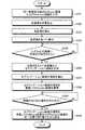
次に、図5および6を用いて、本実施例1に係る制御部26による画像表示の流れについて説明する。図5は、本実施例1に係る制御部26による画像表示の処理手順を示すフローチャートである。また、図6は、本実施例1に係る制御部26による画像表示の流れを示す図である。なお、ここでは、脳のT1W画像、T2W画像およびFlair画像を表示する場合の処理の一例を説明する。Next, the flow of image display by the
図5に示すように、本実施例1に係る制御部26では、まず、位置合せ処理部26aが、同一被検体の脳のT1W画像、T2W画像およびFlair画像を入力し(ステップS101)、入力した各画像を位置合せする(ステップS102)。そして、画像補正処理部26bが、位置合せ処理部26aによって位置合せされた各画像を補正する(ステップS103)。As shown in FIG. 5, in the
このとき、位置合せ処理部26aは、例えば、画像に付帯される患者座標系の位置情報に基づいて、画像の位置合せを行う。そして、位置合せを行った際に、位置合せ処理部26aは、位置合せによって生じた座標の移動量を内部メモリなどの記憶部に画像ごとに記憶させておく。また、画像補正処理部26bは、補正処理によって画像の大きさや形状などの態様を変更した場合には、変更後の画像の大きさや形状などを示す情報を画像ごとに記憶部に記憶させておく。 At this time, the
続いて、表示制御部26eが、画像補正処理部26bによって補正された各画像のうちいずれか一つの画像、例えば、T1W画像を、表示部25が有する表示領域に表示させる(ステップS104)。なお、ここで表示される画像を、以下では「基準画像」と呼ぶ。この基準画像としては、疾患の種類ごとに異なる画像が設定され、操作者による指定に応じて任意に変更することができる。Subsequently, the
そして、図6に示すように、操作者によって、表示されているT1W画像の基準画像41に対して注視点が指定されると(ステップS105,Yes)、関心領域設定部26cが、その注視点をもとに各画像に関心領域を設定する(ステップS106)。なお、図6に示す例は、解剖上の「上前頭回」に関心領域が設定された場合を示している。Then, as shown in FIG. 6, when the operator designates a gazing point with respect to the
ここで、関心領域を設定した際に、関心領域設定部26cは、設定した関心領域の位置を示す位置情報を画像ごとに記憶部に記憶させておく。さらに、関心領域設定部26cは、画像ごとに、設定した関心領域の画像を拡大表示用の所定の大きさに拡大する場合の拡大率を算出し、算出した拡大率を記憶部に記憶させておく。 Here, when the region of interest is set, the region-of-interest setting unit 26c stores position information indicating the position of the set region of interest in the storage unit for each image. Further, the region-of-interest setting unit 26c calculates, for each image, an enlargement ratio when enlarging the set image of the region of interest to a predetermined size for enlargement display, and stores the calculated enlargement ratio in the storage unit. deep.
続いて、特徴解析処理部26dが、特徴解析として、関心領域内の画素値のヒストグラムを作成する。例えば、特徴解析処理部26dは、画素値の平均値や積算値など、統計データのヒストグラムを作成する(ステップS107)。 Subsequently, the feature
その後、表示制御部26eが、画像ごとに関心領域の拡大画像を生成し(ステップS108)、さらに、図6に示すように、特徴解析処理部26dによって作成されたヒストグラムを重畳したT1W画像の拡大画像42を、表示部25が有する表示領域に表示させる。(ステップS109)。Thereafter, the
ここで、拡大画像を生成する際には、表示制御部26eは、記憶部に記憶されている座標の移動量、補正処理によって変更された画像の大きさや形状などを示す情報、関心領域の位置情報に基づいて、画像ごとに関心領域の位置および大きさを特定する。また、表示制御部26eは、記憶部に記憶しておいた拡大率に基づいて、画像ごとに、位置および大きさを特定した関心領域の画像を拡大することで拡大画像を生成する。 Here, when generating the enlarged image, the
そして、操作者によって、表示されている拡大画像42に対して入力部24のキーボードやマウスなどによる所定の画像切り替え操作が行われると(ステップS110,Yes)、表示制御部26eは、図6に示すように、表示部25が有する表示領域の略同一位置に、特徴解析処理部26dによって作成されたヒストグラムをそれぞれ重畳したT1W画像の拡大画像42、T2W画像の拡大画像43、および、Flair画像の拡大画像44を切り替えながら表示させる(ステップS111)。When the operator performs a predetermined image switching operation with the keyboard or mouse of the
なお、図6に示す例は、各画像の画素値から作成したヒストグラムを各画像上に並べて表示する場合を示している。このような場合、例えば、表示制御部26eが、画像のフレームの色とヒストグラムの色とを画像の種類ごとに同じ色で表示するようにしてもよい。その場合、例えば、表示制御部26eは、T1W画像については、フレームおよびヒストグラムを赤色で表示し、T2W画像については、それぞれを緑色で表示し、Flair画像については、それぞれを青色で表示する。これにより、操作者が、各ヒストグラムと各画像との対応付けを容易に行うことができるようになる。The example shown in FIG. 6 shows a case where histograms created from the pixel values of each image are displayed side by side on each image. In such a case, for example, the
上述してきたように、本実施例1では、MRI装置100において、制御部26が有する関心領域設定部26cが、被検体Pの脳のT1W画像、T2W画像およびFlair画像それぞれに関心領域を設定する。また、特徴解析処理部26dが、複数の画像それぞれについて、関心領域設定部26cによって設定された関心領域に含まれる画素の画素値をもとに統計データのヒストグラムを作成する。そして、表示制御部26eが、表示部25が有する表示領域の略同一位置に複数の画像を所定の順序で切り替えながら表示させるとともに、特徴解析処理部26dによって作成されたヒストグラムを同じ表示領域に表示させる。したがって、本実施例1によれば、画像間での視点の移動をともなうことなく、撮像手法の違いによる細部の変化を容易に観察することができる。具体的には、画像とともに統計データのヒストグラムを表示することによって、定性的ではなく定量的な診断を行うことが可能になる。As described above, in the first embodiment, in the
なお、本実施例1では、関心領域が設定された後は拡大画像のみを表示する場合について説明した。しかしながら、本発明はこれに限られるわけではなく、例えば、拡大画像に並べて基準画像を表示するようにしてもよい。図7は、本実施例1に係る制御部26による他の画像表示の流れを示す図である。 In the first embodiment, the case where only the enlarged image is displayed after the region of interest is set has been described. However, the present invention is not limited to this. For example, the reference image may be displayed side by side on the enlarged image. FIG. 7 is a diagram illustrating another flow of image display by the
この場合には、表示制御部26eが、例えば図7に示すように、関心領域を示す基準画像41を拡大画像42〜44に並べて表示する。これにより、検査対象の部位の中で拡大表示されている領域の位置を容易に把握することができるようになる。例えば、脳領域における関心領域の相対的な位置を容易に把握することができるようになる。 In this case, the
また、本実施例1では、図6に示したように、各画像の画素値から作成したヒストグラムを各画像上に並べて表示する場合を説明した。しかしながら、本発明はこれに限られるわけではなく、例えば、表示制御部26eが、画像ごとに、対応する特徴解析の結果(ヒストグラムなど)を表示するようにしてもよい。その場合、表示制御部26eは、複数の画像に関する表示の切り替えに合わせて、画像ごとに特徴解析の結果を切り替えながら表示する。これにより、各画像の特徴量を画像に対応付けて容易に把握することができるようになる。 Further, in the first embodiment, as illustrated in FIG. 6, the case where the histograms created from the pixel values of each image are displayed side by side on each image has been described. However, the present invention is not limited to this. For example, the
また、ここでは、表示制御部26eが、操作者によるキーボードやマウスなどを用いた操作に応じて画像を切り替える場合について説明したが、例えば、一定の時間間隔で自動的に画像を切り替えるようにしてもよい。これにより、キーボードやマウスを操作することができないような状況であっても、複数の画像を切り替えて比較読影を行うことができる。 Further, here, a case has been described in which the
また、表示制御部26eが、操作者からの指定に応じて、画像を切り替える順序を変更してもよい。これにより、操作者は、比較読影する画像の種類に応じて、比較読影が行いやすいように画像表示の順序を変えることができる。 Further, the
ところで、上記実施例1では、脳のT1W画像、T2W画像およびFlair画像を表示する場合について説明した。しかしながら、本発明はこれに限られるわけではなく、他の種類の画像を表示する場合にも同様に適用することが可能である。By the way, in the first embodiment, the case where the T1 W image, T2 W image, and Flair image of the brain are displayed has been described. However, the present invention is not limited to this, and can be similarly applied when displaying other types of images.
従来、特に脳梗塞の検査では、MRI装置によって撮像されたDiffusion画像とPerfusion画像とを組み合わせた評価の有用性が認められている。具体的には、Diffusion画像とPerfusion画像とを用いた脳梗塞の検査では、Diffusion画像およびPerfusion画像それぞれから脳梗塞が疑われる部分を含むセグメンテーション領域を抽出し、抽出したセグメンテーション領域とを重ねた場合に一致しない領域(以下、「ミスマッチエリア」と呼ぶ)を特定する。ここで特定された領域は「可逆性虚血領域」と呼ばれ、早期の血流再開によって救済が可能な領域とみなされる。そのため、この可逆性虚血領域を正確に特定することは、脳梗塞の診断・治療を行ううえで非常に重要である。 Conventionally, particularly in the examination of cerebral infarction, the usefulness of evaluation combining a diffusion image and a perfusion image taken by an MRI apparatus has been recognized. Specifically, in the examination of cerebral infarction using a diffusion image and a perfusion image, when a segmentation region including a portion suspected of cerebral infarction is extracted from each of the diffusion image and the perfusion image, and the extracted segmentation region is overlaid An area that does not match (hereinafter referred to as “mismatch area”) is identified. The region specified here is called a “reversible ischemic region” and is considered as a region that can be relieved by early resumption of blood flow. Therefore, accurately identifying this reversible ischemic region is very important for diagnosis and treatment of cerebral infarction.
そこで、以下では、脳のDiffusion画像とPerfusion画像とを表示する場合を実施例2として説明する。本実施例2では、セグメンテーション領域の境界を常に重畳したまま、Diffusion画像とPerfusion画像とを切り替え表示する。これにより、可逆性虚血領域を正確かつ容易に特定することができるようになり、脳梗塞の診断・治療を迅速に行うことができるようになる。 Therefore, in the following, a case where a brain diffusion image and a perfusion image are displayed will be described as a second embodiment. In the second embodiment, the Diffusion image and the Perfusion image are switched and displayed while the boundary of the segmentation region is always superimposed. As a result, the reversible ischemic region can be identified accurately and easily, and cerebral infarction can be diagnosed and treated quickly.
なお、本実施例2に係るMRI装置は、基本的には、図1および2に示したものと同様の構成を有し、制御部26によって行われる処理が異なるのみであるので、ここでは、図8および9を用いて、制御部26による画像表示の流れについて説明する。 Note that the MRI apparatus according to the second embodiment basically has the same configuration as that shown in FIGS. 1 and 2, and only the processing performed by the
図8は、本実施例2に係る制御部26による画像表示の処理手順を示すフローチャートである。また、図9は、本実施例2に係る制御部26による画像表示の流れを示す図である。なお、ここでは、発症4時間後の脳のDiffusion画像およびPerfusion画像をそれぞれ表示する場合の処理の一例について説明する。 FIG. 8 is a flowchart of the image display processing procedure performed by the
図8に示すように、本実施例2に係る制御部26では、まず、位置合せ処理部26aが、同一被検体の発症4時間後の脳のDiffusion画像およびPerfusion画像をそれぞれ入力し(ステップS201)、入力した各画像を位置合せする(ステップS202)。そして、画像補正処理部26bが、位置合せ処理部26aによって位置合せされた各画像を補正する(ステップS203)。 As shown in FIG. 8, in the
このとき、位置合せ処理部26aは、例えば、画像に付帯される患者座標系の位置情報に基づいて、画像の位置合せを行う。そして、位置合せを行った際に、位置合せ処理部26aは、位置合せによって生じた座標の移動量を内部メモリなどの記憶部に画像ごとに記憶させておく。また、画像補正処理部26bは、補正処理によって画像の大きさや形状などの態様を変更した場合には、変更後の画像の大きさや形状などを示す情報を画像ごとに記憶部に記憶させておく。 At this time, the
続いて、表示制御部26eが、画像補正処理部26bによって補正された各画像を並べて、表示部25が有する表示領域に表示させる(ステップS204)。そして、図9に示すように、操作者によって、表示されているDiffusion画像41およびPerfusion画像52のうち、いずれかの画像に対して注視点が指定されると(ステップS205,Yes)、関心領域設定部26cが、注視点が指定されなかった画像にも同じ位置に注視点を設定する。 Subsequently, the
さらに、関心領域設定部26cは、関心領域として、各注視点における画素を基準にして各画像からセグメンテーション領域を抽出する(ステップS206)。ここで行われるセグメンテーション領域の抽出には、例えば、Region Growing法など、一般的に知られた各種の領域抽出手法を用いることが可能である。 Further, the region-of-interest setting unit 26c extracts a segmentation region from each image as a region of interest based on the pixel at each gazing point (step S206). For the segmentation region extraction performed here, various generally known region extraction methods such as the Region Growing method can be used.
ここで、セグメンテーション領域を抽出した際に、関心領域設定部26cは、抽出したセグメンテーション領域の位置を示す位置情報を画像ごとに記憶部に記憶させておく。 Here, when the segmentation region is extracted, the region-of-interest setting unit 26c stores position information indicating the position of the extracted segmentation region in the storage unit for each image.
続いて、特徴解析処理部26dが、特徴解析として、関心領域設定部26cによって生成されたセグメンテーション領域の境界を各画像から抽出する(ステップS207)。 Subsequently, the feature
その後、表示制御部26eが、図9に示すように、各画像から抽出されたセグメンテーション領域を重畳したPerfusion画像52を表示する(ステップS208)。なお、ここで、表示制御部26eは、Perfusion画像ではなく、各画像から抽出されたセグメンテーション領域を重畳したDiffusion画像を表示してもよい。 Thereafter, as shown in FIG. 9, the
ここで、セグメンテーション領域を重畳する際に、表示制御部26eは、記憶部に記憶されている座標の移動量、補正処理によって変更された画像の大きさや形状などを示す情報、セグメンテーション領域の位置情報に基づいて、画像ごとにセグメンテーション領域の位置を特定したうえで、各セグメンテーション領域を重畳する。 Here, when superimposing the segmentation area, the
そして、操作者によって、表示されている画像に対する入力部24のキーボードやマウスなどによる所定の画像切り替え操作が行われると(ステップS209,Yes)、表示制御部26eは、表示部25が有する表示領域の略同一位置に、特徴解析処理部26dによって各画像から抽出されたセグメンテーション領域を重畳したDiffusion画像51およびPerfusion画像52を切り替えながら表示させる(ステップS210)。なお、図9では、セグメンテーション領域が重畳されたPerfusion画像52を一例として示している。 When the operator performs a predetermined image switching operation on the displayed image using the keyboard or mouse of the input unit 24 (step S209, Yes), the
上述してきたように、本実施例2では、MRI装置100において、制御部26が有する関心領域設定部26cが、関心領域として、所定の領域抽出処理を行うことによって脳のDiffusion画像およびPerfusion画像からセグメンテーション領域を生成し、特徴解析処理部26dが、特徴解析として、関心領域設定部26cによって生成されたセグメンテーション領域の境界を複数の画像ごとに抽出する。そして、表示制御部26eが、特徴解析処理部26dによって抽出された各画像のセグメンテーション領域の境界をそれぞれ重畳し、重畳した各境界を画像に重ねて表示させる。したがって、本実施例2によれば、例えば脳における可逆性虚血領域など、複数の画像におけるセグメンテーション領域を用いて示される領域を正確かつ容易に特定することができるので、診断・治療を迅速かつ効果的に行うことができるようになる。 As described above, in the second embodiment, in the
なお、本実施例2では、同じタイミング(発症4時間後)で撮像されたDiffusion画像およびPerfusion画像を表示する場合について説明した。しかしながら、本発明はこれに限られるわけではなく、例えば、異なるタイミングで撮像された複数の画像を表示する場合にも同様に適用することができる。図10は、本実施例2に係る制御部26による他の画像表示の流れを示す図である。 In addition, the present Example 2 demonstrated the case where the Diffusion image and Perfusion image imaged at the same timing (4 hours after onset) are displayed. However, the present invention is not limited to this. For example, the present invention can be similarly applied to a case where a plurality of images captured at different timings are displayed. FIG. 10 is a diagram illustrating another image display flow by the
例えば、図10に示すように、発症4時間後のDiffusion画像61、発症4時間後のPerfusion画像62、発症14日後のT2W画像63を表示する場合には、表示制御部26eが、Diffusion画像61から抽出されたセグメンテーション領域の境界Aと、Perfusion画像62から抽出されたセグメンテーション領域の境界Bと、T2W画像63から抽出されたセグメンテーション領域の境界Cとをそれぞれ重畳したうえで、各画像を切り替え表示する。ここで、境界Cは、組織が壊死している領域を示すことになる。なお、図10では、境界A〜Cが重畳された発症14日後のT2W画像63を一例として示している。For example, as shown in FIG. 10, when displaying a diffusion image 61 4 hours after the onset, a
このように、発症してから時間が経過した組織画像(例えば、T2W画像)のセグメンテーション領域の境界を常に表示し、さらに、発症直後の機能画像(例えば、Diffusion画像やPerfusion画像)のセグメンテーション領域の境界を重畳表示させることによって、病変部位について発症直後からの症状の経過を効率よく観察することができる。Thus, onset time after elapse tissue image (e.g., T 2W image) always show the boundaries of the segmentation region of the further segmentation immediately after onset functional image (e.g., Diffusion image and Perfusion Image) By displaying the boundary of the region in a superimposed manner, it is possible to efficiently observe the progress of the symptom immediately after the onset of the lesion site.
さらに、表示制御部26eが、各境界を重畳表示させる際に、それぞれの境界の色を変えるようにしてもよい。これにより、それぞれの領域を容易に識別することができるようになる。 Furthermore, when the
また、実施例1および2では、本発明をMRI装置に適用した場合について説明したが、本発明はこれに限られるわけではなく、他の画像診断装置にも同様に適用することができる。例えば、X線診断装置やX線CT装置、超音波診断装置、SPECT(Single Photon Emission Computed Tomography)装置、PET(Positron Emission Tomography)装置などにも本発明を同様に適用することができる。 In the first and second embodiments, the case where the present invention is applied to an MRI apparatus has been described. However, the present invention is not limited to this, and can be similarly applied to other diagnostic imaging apparatuses. For example, the present invention can be similarly applied to an X-ray diagnostic apparatus, an X-ray CT apparatus, an ultrasonic diagnostic apparatus, a SPECT (Single Photon Emission Computed Tomography) apparatus, a PET (Positron Emission Tomography) apparatus, and the like.
また、実施例1および2では、複数の画像を位置合せしたうえで、各画像からセグメンテーション領域を抽出し、抽出したセグメンテーション領域を各画像上で重ねて表示する場合について説明した。この一方で、例えば、各画像を位置合せする前に、それぞれの画像からセグメンテーション領域を抽出し、抽出したセグメンテーション領域のみを位置合せしてもよい。 In the first and second embodiments, a case has been described in which a plurality of images are aligned, a segmentation region is extracted from each image, and the extracted segmentation regions are displayed over each image. On the other hand, for example, before aligning each image, a segmentation region may be extracted from each image, and only the extracted segmentation region may be aligned.
その場合には、例えば、表示制御部26eが、まず、特徴解析処理部26dによって抽出された各画像のセグメンテーション領域をそれぞれ位置合せしたうえで重畳する。そして、表示制御部26eは、重畳したセグメンテーション領域と表示対象の画像との位置合せを行った後に、それぞれを重ねて表示させる。これにより、複数の画像それぞれについて画像全体を位置合せする必要がなくなるので、位置合せに関する処理の負荷を軽減することができる。 In that case, for example, the
また、実施例1および2では、本発明をMRI装置に適用した場合について説明したが、本発明はこれに限られるわけではなく、MRI装置やX線診断装置、X線CT装置、超音波診断装置、SPECT装置、PET装置、内視鏡等の各種画像診断装置によって撮像された画像を表示する画像表示装置(「ビューワ」とも呼ばれる)に適用することもできる。 In the first and second embodiments, the case where the present invention is applied to the MRI apparatus has been described. However, the present invention is not limited to this, and the MRI apparatus, the X-ray diagnostic apparatus, the X-ray CT apparatus, and the ultrasonic diagnosis are used. The present invention can also be applied to an image display device (also referred to as “viewer”) that displays an image captured by various image diagnostic devices such as a device, a SPECT device, a PET device, and an endoscope.
そこで、以下では、本発明を画像表示装置に適用した場合を実施例3として説明する。まず、図11を用いて、本実施例3に係る画像表示装置の構成について説明する。図11は、本実施例3に係る画像表示装置200の構成を示す機能ブロック図である。図11に示すように、本実施例3に係る画像表示装置200は、通信部210、記憶部220、入力部230、表示部240および制御部250を有する。 Therefore, hereinafter, a case where the present invention is applied to an image display device will be described as a third embodiment. First, the configuration of the image display apparatus according to the third embodiment will be described with reference to FIG. FIG. 11 is a functional block diagram illustrating the configuration of the image display apparatus 200 according to the third embodiment. As illustrated in FIG. 11, the image display apparatus 200 according to the third embodiment includes a
通信部210は、ネットワークを介してPACS(Picture Archiving and Communication System)や画像データベース等との間でやり取りされる情報の送受信を制御する。ここで、PACSとは、ネットワークを介して接続された各種画像診断装置や画像保管装置などが有する画像管理システムである。また、画像データベースとは、各種画像診断装置によって撮像された各種画像を保管するデータベースである。 The
かかるPACSまたは画像データベースから送信される画像データは、典型的には断層画像または投影画像であるが、例えば、多断面の断層画像や、ボクセル表現されたボリュームデータなども含まれる。または、送信される画像データは画像生成前のデータであってもよい。例えば、MRI装置では、周波数空間のデータの相関を測ることで移動量を算出し、位置あわせが行われる場合がある。さらに、これらの画像データには、撮影パラメータやスライス(撮像)位置、撮影時刻、撮像条件等の情報が付帯されている。 The image data transmitted from the PACS or the image database is typically a tomographic image or a projection image, but includes, for example, a multi-section tomographic image, volume data represented by voxels, and the like. Alternatively, the transmitted image data may be data before image generation. For example, in an MRI apparatus, the amount of movement may be calculated by measuring the correlation of data in the frequency space, and alignment may be performed. Furthermore, information such as imaging parameters, slice (imaging) positions, imaging times, imaging conditions, and the like are attached to these image data.
記憶部220は、通信部210を介してPACSや画像データベース等から受信した画像や、制御部250によって実行される各種プログラムなどの各種情報を記憶する。 The
入力部230は、操作者からの各種指示や情報入力を受け付ける。この入力部230としては、マウスやトラックボールなどのポインティングデバイスやキーボード等の入力デバイスを適宜に利用可能である。 The
表示部240は、画像診断装置によって撮像された画像などの各種情報を表示する。この表示部240としては、液晶表示器などの表示デバイスを適宜に利用可能である。 The
制御部250は、図示していないCPUやメモリ等を有し、画像表示装置200の全体制御を行う。本実施例3では、この制御部250が、被検体の同一部位を含む複数の画像それぞれに関心領域を設定し、各画像について、設定した関心領域に含まれる画素の画素値をもとに特徴解析を行う。そして、表示部240が有する表示領域の略同一位置に各画像を所定の順序で切り替えながら表示させるとともに、特徴解析の結果を同じ表示領域に表示させる。これにより、本実施例3では、画像間での視点の移動をともなうことなく、撮像手法の違いによる細部の変化を容易に観察することができるようにしている。 The
具体的には、制御部250は、特に、位置合せ処理部250a、画像補正処理部250b、関心領域設定部250c、特徴解析処理部250dおよび表示制御部250eを有する。これら各部が有する機能は、基本的には、それぞれ、図2に示した位置合せ処理部26a、画像補正処理部26b、関心領域設定部26c、特徴解析処理部26dおよび表示制御部26eと同様であるので、ここでは詳細な説明を省略する。 Specifically, the
次に、図12および13を用いて、本実施例3に係る制御部250による画像表示の流れについて説明する。図12は、本実施例3に係る制御部250による画像表示の処理手順を示すフローチャートである。また、図13は、本実施例3に係る制御部250による画像表示の流れを示す図である。なお、ここでは、X線CT装置を用いたダイナミック撮像(以下、「ダイナミックCT撮像」と呼ぶ)によって時系列的に撮像された肝臓の画像を表示する場合の処理の一例について説明する。 Next, the flow of image display by the
肝臓のダイナミック撮像では、被検体に造影剤が注入された後に、複数の異なるタイミングで撮像が行われる。このタイミングとしては、例えば、動脈優位相、門脈相、平衡相があり、これら各相における造影剤の残留濃度が重要な情報である。そこで、本実施例3では、ダイナミックCT撮像によって得られた肝臓の動脈優位相、門脈相、平衡相における画像を表示する場合について説明する。 In dynamic imaging of the liver, imaging is performed at a plurality of different timings after the contrast medium is injected into the subject. The timing includes, for example, an arterial dominant phase, a portal vein phase, and an equilibrium phase, and the residual concentration of the contrast agent in each phase is important information. Therefore, in the third embodiment, a case will be described in which images in the arterial dominant phase, portal phase, and equilibrium phase of the liver obtained by dynamic CT imaging are displayed.
図12に示すように、本実施例3に係る制御部250では、まず、位置合せ処理部250aが、ダイナミックCT撮像によって得られた同一被検体の肝臓の動脈優位相、門脈相、平衡相における画像をそれぞれ入力し(ステップS301)、入力した各画像を位置合せする(ステップS302)。なお、ここで行われる画像の位置合せ処理は、省略することも可能である。それにより、計算の処理時間を短縮することができる。 As shown in FIG. 12, in the
そして、画像補正処理部250bが、位置合せ処理部250aによって位置合せされた各画像を補正する(ステップS303)。 Then, the image
続いて、表示制御部250eが、図13に示すように、画像補正処理部250bによってそれぞれ補正された肝臓の動脈優位相の画像71、門脈相の画像72、平衡相の画像73を並べて、表示部240が有する表示領域に表示させる(ステップS304)。 Subsequently, as shown in FIG. 13, the display control unit 250e arranges the
そして、図13に示すように、操作者によって、表示されている動脈優位相の画像71、門脈相の画像72、平衡相の画像73のうち、いずれかの画像に対して関心領域(画像71におけるD、画像72におけるE、または、画像73におけるF)が指定されると(ステップS305,Yes)、関心領域設定部250cが、関心領域が指定されなかった相の画像にも、それぞれ同じ位置に同様の関心領域を設定する。 Then, as shown in FIG. 13, a region of interest (image) is displayed on any one of the displayed arterial
続いて、特徴解析処理部250dが、関心領域設定部250cによって設定された関心領域をもとに各画像に異常領域および正常領域を設定する(ステップS306)。具体的には、特徴解析処理部250dは、図13に示すように、関心領域設定部250cによって設定された関心領域を異常領域として設定し、その異常領域を所定量だけ拡げた拡張領域を正常領域として設定する。 Subsequently, the feature analysis processing unit 250d sets an abnormal region and a normal region in each image based on the region of interest set by the region of interest setting unit 250c (step S306). Specifically, as shown in FIG. 13, the feature analysis processing unit 250d sets the region of interest set by the region-of-interest setting unit 250c as an abnormal region, and normalizes an expanded region obtained by expanding the abnormal region by a predetermined amount. Set as area.
そして、特徴解析処理部250dは、特徴解析として、各画像の画素値をもとに異常領域および正常領域のTDC(Time Density Curve)を算出する(ステップS307)。なお、このとき、特徴解析処理部250dは、画素値を表すTDCを算出してもよいが、例えば、造影剤が流入する前に撮像された画像の画素値を基準とし、その画素値との差分を表すTDCを算出してもよい。 Then, the feature analysis processing unit 250d calculates TDC (Time Density Curve) of the abnormal region and the normal region based on the pixel value of each image as the feature analysis (step S307). At this time, the feature analysis processing unit 250d may calculate the TDC representing the pixel value. For example, the feature analysis processing unit 250d uses the pixel value of the image captured before the contrast agent flows in as a reference, A TDC representing the difference may be calculated.
その後、表示制御部250eが、図13に示すように、特徴解析処理部250dによって生成されたTDCのグラフ75を表示部240が有する表示領域に表示させる(ステップS308)。なお、グラフ75において、Hは正常領域のTDCを示し、Gは異常領域のTDCを示している。 Thereafter, as shown in FIG. 13, the display control unit 250e displays the
なお、このとき、表示制御部250eは、図13に示すように、動脈優位相の画像71、門脈相の画像72、平衡相の画像73それぞれに設定された関心領域(画像71〜73におけるD、E、F)と、TDCのグラフ75において動脈優位相、門脈相、平衡相を示す線(グラフ75におけるD、E、Fの線)とを相ごとに同じ色に表示してもよい。これにより、各相の画像と各相における濃度(画素値の大きさに対応する)とを容易に対応付けて観察することができる。 At this time, as shown in FIG. 13, the display control unit 250e displays the region of interest set in each of the arterial
続いて、表示制御部250eは、動脈優位相の画像71、門脈相の画像72および平衡相の画像73それぞれから異常領域および正常領域を包含する部分の拡大画像を生成した後に(ステップS309)、関心領域設定部250cによって設定された異常領域および正常領域を重畳した動脈優位相の拡大画像74を、表示部240が有する表示領域に表示させる(ステップS310)。なお、ここで、表示制御部250eは、動脈優位相の拡大画像74ではなく、異常領域および正常領域を重畳した門脈相または平衡相の拡大画像を表示してもよい。 Subsequently, the display control unit 250e generates an enlarged image of a portion including the abnormal region and the normal region from the arterial
そして、操作者によって、表示されている画像に対する入力部230のキーボードやマウスなどによる所定の画像切り替え操作が行われると(ステップS311,Yes)、表示制御部250eは、表示部240が有する表示領域の略同一位置に、関心領域設定部250cによって設定された異常領域および正常領域を重畳した動脈優位相、門脈相および平衡相の拡大画像を切り替えながら表示させる(ステップS312)。 When the operator performs a predetermined image switching operation on the displayed image using the keyboard or mouse of the input unit 230 (Yes in step S311), the display control unit 250e displays the display area of the
なお、このとき、表示制御部250eは、図13に示すように、拡大画像において異常領域を示す線(画像74におけるG)と、TDCのグラフ75において異常領域のTDCを示す曲線(グラフ75におけるG)とを同じ色で表示し、拡大画像において正常領域を示す線(画像74におけるH)と、TDCのグラフ75において正常領域のTDCを示す曲線(グラフ75におけるH)とを同じ色で表示してもよい。これにより、TDCのグラフ75上の曲線と、動脈優位相の画像71、門脈相の画像72および平衡相の画像73に重畳された異常領域および正常領域とを容易に対応付けて観察することができる。 At this time, as shown in FIG. 13, the display control unit 250e displays a line (G in the image 74) indicating an abnormal area in the enlarged image and a curve (in the graph 75) indicating the TDC of the abnormal area in the
あるいは、切り替え表示された画像に対応する図13のD、E、Fのいずれかを強調表示してもよい。 Alternatively, any one of D, E, and F in FIG. 13 corresponding to the switched display image may be highlighted.
上述してきたように、本実施例3では、画像表示装置200において、制御部250の関心領域設定部250cが、ダイナミックCT撮像によって得られた肝臓の複数の画像それぞれに関心領域を設定し、特徴解析処理部250dが、複数の画像それぞれについて、関心領域設定部250cによって設定された関心領域に含まれる画素の画素値をもとに異常領域および正常領域を設定し、設定した異常領域および正常領域のTDCを算出する。そして、表示制御部250eが、表示部240が有する表示領域の略同一位置に複数の画像を所定の順序で切り替えながら表示させるとともに、異常領域および正常領域、ならびに、それぞれの領域のTDCを同じ表示領域に表示させる。したがって、本実施例3によれば、画像間での視点の移動をともなうことなく、撮像手法の違いによる細部の変化を容易に観察することができる。具体的には、肝臓における造影剤の貯留程度を視覚的に確認することができる。 As described above, in the third embodiment, in the image display apparatus 200, the region-of-interest setting unit 250c of the
なお、上記実施例で用いた画像以外に、例えば、異なる撮像条件(撮像時間も含む)下で撮像された複数のCT画像、MR画像、超音波画像、SPECT画像、PET画像、内視鏡画像についても、上記実施例で説明した画像の切り替え表示および関心領域の特徴量表示を同様に適用することが可能である。または、これらの画像を組み合わせた画像の表示にも同様に適用することが可能である。この組み合わせとしては、例えば、CTとMR、CTとPET、CTとSPECT、DSA(Digital Subtraction Angiographies)とMR、PETとMR、PETとUS(超音波診断装置)、SPECTとMR、SPECTとUS、USとCT、USとMR、X−ray(X線診断装置)とCT、X−rayとMR、X−rayとUSなどがあげられる。 In addition to the images used in the above embodiments, for example, a plurality of CT images, MR images, ultrasound images, SPECT images, PET images, and endoscopic images captured under different imaging conditions (including imaging time). Also for the above, it is possible to similarly apply the image switching display and the feature amount display of the region of interest described in the above embodiment. Alternatively, the present invention can be similarly applied to display of an image obtained by combining these images. Examples of this combination include CT and MR, CT and PET, CT and SPECT, DSA (Digital Subtraction Angiographies) and MR, PET and MR, PET and US (ultrasound diagnostic apparatus), SPECT and MR, SPECT and US, US and CT, US and MR, X-ray (X-ray diagnostic apparatus) and CT, X-ray and MR, X-ray and US, and the like.
以上のように、実施例1、2および3によれば、同一部位に関して様々な手法で撮像された複数種類の画像が画面の略同一位置に切り替えて表示され、特徴量も併せて表示されるので、関心部位の画面位置に視点を定めたまま、撮像手法の違いによる細部の変化も容易に観察することが可能となる。それにより読影者は、読影効率を向上させ、迅速な診断・治療を実施することが可能となる。また統計結果も表示されることから、定性的でなく定量的な診断を行うことが可能となる。 As described above, according to the first, second, and third embodiments, a plurality of types of images captured by various methods with respect to the same part are displayed by switching to substantially the same position on the screen, and the feature amount is also displayed. Therefore, it is possible to easily observe a change in details due to a difference in imaging method while keeping the viewpoint at the screen position of the region of interest. As a result, the radiogram interpreter can improve the radiogram interpretation efficiency and perform quick diagnosis and treatment. Since the statistical result is also displayed, it is possible to make a quantitative diagnosis rather than qualitative.
すなわち、実施例1、2および3によれば、画像診断に効果的な画像と特徴量とを表示することで、複数の医用画像を用いて、各画像の解剖的な細部(関心領域)を視線移動なしに比較読影し、疾患の有無の判断や良悪性の鑑別、治療フロー決定を行うことができる。 That is, according to the first, second, and third embodiments, by displaying an image and feature amount effective for image diagnosis, an anatomical detail (region of interest) of each image can be obtained using a plurality of medical images. Comparative interpretation without gaze movement can be performed to determine the presence or absence of disease, discrimination between benign and malignant, and treatment flow determination.
以上のように、本発明に係る画像表示装置、画像表示方法および磁気共鳴イメージング装置は、各種画像の比較読影を行う場合に有用であり、特に、各種画像の特徴を把握したうえで、定量的な診断を行うことが必要な場合に適している。 As described above, the image display apparatus, the image display method, and the magnetic resonance imaging apparatus according to the present invention are useful for comparative interpretation of various images, and in particular, quantitatively after understanding the characteristics of various images. It is suitable when it is necessary to make a simple diagnosis.
100 MRI装置
1 静磁場磁石
2 傾斜磁場コイル
3 傾斜磁場電源
4 寝台
4a 天板
5 寝台制御部
6 送信RFコイル
7 送信部
8 受信RFコイル
9 受信部
10 シーケンス制御部
20 計算機システム
21 インタフェース部
22 画像再構成部
23 記憶部
24 入力部
25 表示部
26 制御部
26a 位置合せ処理部
26b 画像補正処理部
26c 関心領域設定部
26d 特徴解析処理部
26e 表示制御部
200 画像表示装置
210 通信部
220 記憶部
230 入力部
240 表示部
250 制御部
250a 位置合せ処理部
250b 画像補正処理部
250c 関心領域設定部
250d 特徴解析処理部
250e 表示制御部DESCRIPTION OF
Claims (20)
Translated fromJapanese前記複数の画像それぞれについて、前記関心領域設定部によって設定された前記関心領域に含まれる画素の画素値をもとに特徴解析を行う特徴解析部と、
表示部が有する表示領域の略同一位置に前記複数の画像を所定の順序で切り替えながら表示させるとともに、前記複数の画像の表示の切り替えに連動して、前記特徴解析部によって画像ごとに得られた複数の前記特徴解析の結果を前記表示領域の略同一位置に切り替えながら表示させる表示制御部と、
を備える、画像表示装置。For eachdifferent plurality of images including the same region of the subject taken by the image diagnosisapparatus, a ROI setting unit for setting a region of interestin common to the same site contained in each image,
For each of the plurality of images, a feature analysis unit that performs feature analysis based on pixel values of pixels included in the region of interest set by the region of interest setting unit;
Causes display while switching the plurality of images in substantially the same position of the display area of the display unit in a predetermined order,in conjunction with the switching of the display of the plurality of images,obtained every Hence image on the feature analyzing unitA display control unit that displaysa plurality of results of the feature analysiswhile switching to substantially the same position in the display area ;
An image display device comprising:
前記複数の画像それぞれについて、前記関心領域設定部によって抽出されたセグメンテーション領域の境界を抽出する特徴解析を行う特徴解析部と、 For each of the plurality of images, a feature analysis unit that performs a feature analysis that extracts a boundary of the segmentation region extracted by the region of interest setting unit;
表示部が有する表示領域の略同一位置に前記複数の画像を所定の順序で切り替えながら表示させるとともに、前記複数の画像の表示の切り替えに連動して、前記特徴解析部によって画像ごとに抽出された複数のセグメンテーション領域の境界を同時に各画像に重畳して表示させる表示制御部と、 The plurality of images are displayed while switching in a predetermined order at substantially the same position in the display area of the display unit, and extracted for each image by the feature analysis unit in conjunction with the switching of the display of the plurality of images. A display control unit that simultaneously superimposes and displays the boundaries of a plurality of segmentation regions on each image;
を備える、画像表示装置。 An image display device comprising:
前記関心領域設定部によって前記複数の画像それぞれに設定された前記関心領域に含まれる画素の画素値をもとにTDC(Time Density Curve)を算出する特徴解析を行う特徴解析部と、 A feature analysis unit that performs a feature analysis to calculate a TDC (Time Density Curve) based on pixel values of pixels included in the region of interest set in each of the plurality of images by the region of interest setting unit;
表示部が有する表示領域の略同一位置に前記複数の画像を所定の順序で切り替えながら表示させるとともに、前記特徴解析部によって算出されたTDCを表示させ、さらに、前記複数の画像の表示の切り替えに連動して、前記関心領域設定部によって設定された関心領域と前記TDCとの対応を示す情報を各画像に重畳して表示させる表示制御部と、 The plurality of images are displayed while switching in a predetermined order at substantially the same position in the display area of the display unit, the TDC calculated by the feature analysis unit is displayed, and further, the display of the plurality of images is switched. In conjunction with the display control unit, the information indicating the correspondence between the region of interest set by the region of interest setting unit and the TDC is superimposed and displayed on each image;
を備える、画像表示装置。 An image display device comprising:
前記特徴解析部は、前記位置合せ部による位置合せが行われた各画像について、前記特徴解析を行う、請求項1、2又は3に記載の画像表示装置。An alignment unit for aligning the plurality of images;
The feature analyzing unit, for each image aligning by the alignment unit has been performed, it performs the feature analysis, image display apparatus according to claim1, 2 or 3.
前記複数の画像それぞれについて、前記関心領域に含まれる画素の画素値をもとに特徴解析を行い、
表示部が有する表示領域の略同一位置に前記複数の画像を所定の順序で切り替えながら表示させるとともに、前記複数の画像の表示の切り替えに連動して、画像ごとに得られた複数の前記特徴解析の結果を前記表示領域の略同一位置に切り替えながら表示させる、
ことを含む、画像表示方法。For eachdifferent plurality of images including the same region of the subject taken by the imagingdevice, and set a region of interestin common to the same site contained in each image,
For each of the plurality of images, perform a feature analysis based on pixel values of pixels included in the region of interest,
The plurality of images are displayed at substantially the same position in a display area of the display unit while switching the plurality of images in a predetermined order,and a plurality of the feature analysisobtained for each image in conjunction with the switching of the display of the plurality of images.Display the resultwhile switching to substantially the same position in the display area ,
An image display method.
前記複数の画像それぞれについて、前記セグメンテーション領域の境界を抽出する特徴解析を行い、 For each of the plurality of images, perform a feature analysis to extract the boundary of the segmentation region,
表示部が有する表示領域の略同一位置に前記複数の画像を所定の順序で切り替えながら表示させるとともに、前記複数の画像の表示の切り替えに連動して、画像ごとに抽出された複数のセグメンテーション領域の境界を同時に各画像に重畳して表示させる、 The plurality of images are displayed while being switched in a predetermined order at substantially the same position in the display area of the display unit, and the plurality of segmentation areas extracted for each image are interlocked with the display switching of the plurality of images. Display the border superimposed on each image at the same time.
ことを含む、画像表示方法。 An image display method.
前記複数の画像それぞれに設定された前記関心領域に含まれる画素の画素値をもとにTDC(Time Density Curve)を算出する特徴解析を行い、 Performing a feature analysis that calculates a TDC (Time Density Curve) based on pixel values of pixels included in the region of interest set in each of the plurality of images,
表示部が有する表示領域の略同一位置に前記複数の画像を所定の順序で切り替えながら表示させるとともに、前記TDCを表示させ、さらに、前記複数の画像の表示の切り替えに連動して、前記関心領域と前記TDCとの対応を示す情報を各画像に重畳して表示させる、 The plurality of images are displayed while switching in a predetermined order at substantially the same position of the display area of the display unit, the TDC is displayed, and the region of interest is linked with the switching of the display of the plurality of images. And information indicating the correspondence between the TDC and the TDC are superimposed on each image and displayed.
ことを含む、画像表示方法。 An image display method.
前記撮像部によって撮像された前記複数の画像それぞれについて、各画像に含まれる同一部位に共通して関心領域を設定する関心領域設定部と、
前記複数の画像それぞれについて、前記関心領域設定部によって設定された前記関心領域に含まれる画素の画素値をもとに特徴解析を行う特徴解析部と、
表示部が有する表示領域の略同一位置に前記複数の画像を所定の順序で切り替えながら表示させるとともに、前記複数の画像の表示の切り替えに連動して、前記特徴解析部によって画像ごとに得られた複数の前記特徴解析の結果を前記表示領域の略同一位置に切り替えながら表示させる表示制御部と、
を備える、磁気共鳴イメージング装置。An imaging unit that captures a plurality ofdifferent types of images including the same part of the subject;
About each of the plurality of images captured by the imagingunit, and the region-of-interest setting unit that sets a region of interestin common to the same site contained in each image,
For each of the plurality of images, a feature analysis unit that performs feature analysis based on pixel values of pixels included in the region of interest set by the region of interest setting unit;
Causes display while switching the plurality of images in substantially the same position of the display area of the display unit in a predetermined order,in conjunction with the switching of the display of the plurality of images,obtained every Hence image on the feature analyzing unitA display control unit that displaysa plurality of results of the feature analysiswhile switching to substantially the same position in the display area ;
A magnetic resonance imaging apparatus comprising:
前記撮像部によって撮像された前記複数の画像それぞれについて、所定の領域抽出処理を行うことによってセグメンテーション領域を抽出する関心領域設定部と、 A region-of-interest setting unit that extracts a segmentation region by performing a predetermined region extraction process for each of the plurality of images captured by the imaging unit;
前記複数の画像それぞれについて、前記関心領域設定部によって抽出されたセグメンテーション領域の境界を抽出する特徴解析を行う特徴解析部と、 For each of the plurality of images, a feature analysis unit that performs a feature analysis that extracts a boundary of the segmentation region extracted by the region of interest setting unit;
表示部が有する表示領域の略同一位置に前記複数の画像を所定の順序で切り替えながら表示させるとともに、前記複数の画像の表示の切り替えに連動して、前記特徴解析部によって画像ごとに抽出された複数のセグメンテーション領域の境界を同時に各画像に重畳して表示させる表示制御部と、 The plurality of images are displayed while switching in a predetermined order at substantially the same position in the display area of the display unit, and extracted for each image by the feature analysis unit in conjunction with the switching of the display of the plurality of images. A display control unit that simultaneously superimposes and displays the boundaries of a plurality of segmentation regions on each image;
を備える、磁気共鳴イメージング装置。 A magnetic resonance imaging apparatus comprising:
前記撮像部によって撮像された前記複数の画像それぞれに関心領域を設定する関心領域設定部と、 A region-of-interest setting unit that sets a region of interest in each of the plurality of images captured by the imaging unit;
前記関心領域設定部によって前記複数の画像それぞれに設定された前記関心領域に含まれる画素の画素値をもとにTDC(Time Density Curve)を算出する特徴解析を行う特徴解析部と、 A feature analysis unit that performs a feature analysis to calculate a TDC (Time Density Curve) based on pixel values of pixels included in the region of interest set in each of the plurality of images by the region of interest setting unit;
表示部が有する表示領域の略同一位置に前記複数の画像を所定の順序で切り替えながら表示させるとともに、前記特徴解析部によって算出されたTDCを表示させ、さらに、前記複数の画像の表示の切り替えに連動して、前記関心領域設定部によって設定された関心領域と前記TDCとの対応を示す情報を各画像に重畳して表示させる表示制御部と、 The plurality of images are displayed while switching in a predetermined order at substantially the same position in the display area of the display unit, the TDC calculated by the feature analysis unit is displayed, and further, the display of the plurality of images is switched. In conjunction with the display control unit, the information indicating the correspondence between the region of interest set by the region of interest setting unit and the TDC is superimposed and displayed on each image;
を備える、磁気共鳴イメージング装置。 A magnetic resonance imaging apparatus comprising:
Priority Applications (5)
| Application Number | Priority Date | Filing Date | Title |
|---|---|---|---|
| JP2009208519AJP5562598B2 (en) | 2008-10-24 | 2009-09-09 | Image display apparatus, image display method, and magnetic resonance imaging apparatus |
| US12/603,961US9706943B2 (en) | 2008-10-24 | 2009-10-22 | Image display apparatus, image display method, and magnetic resonance imaging apparatus |
| CN201210007869.XACN102525467B (en) | 2008-10-24 | 2009-10-23 | Image display device, method for displaying image and MR imaging apparatus |
| CN200910207021ACN101721211A (en) | 2008-10-24 | 2009-10-23 | Image display device, image display method, and magnetic resonance imaging device |
| US13/493,242US20120249498A1 (en) | 2008-10-24 | 2012-06-11 | Image display apparatus, image display method, and magnetic resonance imaging apparatus |
Applications Claiming Priority (3)
| Application Number | Priority Date | Filing Date | Title |
|---|---|---|---|
| JP2008274842 | 2008-10-24 | ||
| JP2008274842 | 2008-10-24 | ||
| JP2009208519AJP5562598B2 (en) | 2008-10-24 | 2009-09-09 | Image display apparatus, image display method, and magnetic resonance imaging apparatus |
Publications (2)
| Publication Number | Publication Date |
|---|---|
| JP2010119831A JP2010119831A (en) | 2010-06-03 |
| JP5562598B2true JP5562598B2 (en) | 2014-07-30 |
Family
ID=42118145
Family Applications (1)
| Application Number | Title | Priority Date | Filing Date |
|---|---|---|---|
| JP2009208519AActiveJP5562598B2 (en) | 2008-10-24 | 2009-09-09 | Image display apparatus, image display method, and magnetic resonance imaging apparatus |
Country Status (3)
| Country | Link |
|---|---|
| US (2) | US9706943B2 (en) |
| JP (1) | JP5562598B2 (en) |
| CN (2) | CN101721211A (en) |
Cited By (1)
| Publication number | Priority date | Publication date | Assignee | Title |
|---|---|---|---|---|
| KR20190098463A (en)* | 2018-02-14 | 2019-08-22 | 가톨릭대학교 산학협력단 | Medical image information reading apparatus and reading method |
Families Citing this family (45)
| Publication number | Priority date | Publication date | Assignee | Title |
|---|---|---|---|---|
| US7944207B2 (en)* | 2005-06-14 | 2011-05-17 | Hitachi Medical Corporation | Magnetic resonance imaging apparatus and method |
| JP5562598B2 (en)* | 2008-10-24 | 2014-07-30 | 株式会社東芝 | Image display apparatus, image display method, and magnetic resonance imaging apparatus |
| WO2011070464A2 (en)* | 2009-12-10 | 2011-06-16 | Koninklijke Philips Electronics N.V. | A system for rapid and accurate quantitative assessment of traumatic brain injury |
| CN102762157B (en) | 2009-12-22 | 2015-04-01 | 库克医学技术有限责任公司 | Medical device with detachable pivotable caliper |
| WO2012008296A1 (en)* | 2010-07-15 | 2012-01-19 | 株式会社 日立メディコ | Medical image capture device and image capture slice determination method |
| JP5765899B2 (en)* | 2010-08-30 | 2015-08-19 | キヤノン株式会社 | Control apparatus and control method |
| US20120113146A1 (en)* | 2010-11-10 | 2012-05-10 | Patrick Michael Virtue | Methods, apparatus and articles of manufacture to combine segmentations of medical diagnostic images |
| JP5292440B2 (en)* | 2011-06-03 | 2013-09-18 | 富士フイルム株式会社 | Ultrasonic diagnostic equipment |
| JP5173053B2 (en)* | 2011-07-19 | 2013-03-27 | 株式会社東芝 | Image processing system, apparatus, method, and medical image diagnostic apparatus |
| US10049445B2 (en)* | 2011-07-29 | 2018-08-14 | Canon Kabushiki Kaisha | Image processing apparatus and image processing method of a three-dimensional medical image |
| WO2013191036A1 (en)* | 2012-06-20 | 2013-12-27 | 株式会社 東芝 | Medical image processing device, magnetic resonance imaging device, medical image processing method, and magnetic resonance imaging method |
| DE102012222073B4 (en)* | 2012-12-03 | 2014-12-18 | Siemens Aktiengesellschaft | Method for evaluating image data sets and combination image recording device |
| CN104103083A (en)* | 2013-04-03 | 2014-10-15 | 株式会社东芝 | Image processing device, method and medical imaging device |
| WO2014184887A1 (en)* | 2013-05-15 | 2014-11-20 | 株式会社日立製作所 | Image diagnosis support system |
| CN103793908A (en)* | 2014-01-17 | 2014-05-14 | 首都医科大学 | Method for constructing prediction model of multifunctional veins based on brain nuclear magnetic resonance image |
| PL2933743T3 (en)* | 2014-04-18 | 2019-10-31 | Univ Rennes | Method of characterizing molecular diffusion within a body from a set of diffusion-weighted magnetic resonance signals and apparatus for carrying out such a method |
| JP6510189B2 (en)* | 2014-06-23 | 2019-05-08 | キヤノンメディカルシステムズ株式会社 | Medical image processing device |
| DE102015202494B4 (en)* | 2015-02-12 | 2023-10-19 | Siemens Healthcare Gmbh | Evaluation of a dynamic contrast agent distribution |
| CN105989596B (en)* | 2015-02-12 | 2019-09-10 | 东芝医疗系统株式会社 | Medical image processing devices and method and MR imaging apparatus |
| JP6501647B2 (en)* | 2015-06-23 | 2019-04-17 | キヤノン株式会社 | IMAGE PROCESSING APPARATUS, CONTROL METHOD THEREOF, AND PROGRAM |
| JP6800630B2 (en)* | 2015-09-10 | 2020-12-16 | キヤノンメディカルシステムズ株式会社 | Magnetic resonance imaging device and image processing device |
| US10080508B2 (en)* | 2015-09-10 | 2018-09-25 | Toshiba Medical Systems Corporation | Magnetic resonance imaging apparatus and image processing apparatus |
| JP6615603B2 (en)* | 2015-12-24 | 2019-12-04 | キヤノンメディカルシステムズ株式会社 | Medical image diagnostic apparatus and medical image diagnostic program |
| JP6745633B2 (en)* | 2016-04-13 | 2020-08-26 | キヤノン株式会社 | Image processing apparatus, image processing method, and program |
| JP2018000374A (en)* | 2016-06-29 | 2018-01-11 | ゼネラル・エレクトリック・カンパニイ | Image processor and program |
| WO2018093434A1 (en) | 2016-11-21 | 2018-05-24 | Siemens Healthcare Gmbh | Method for recording diagnostic measurement data of a head via a magnetic resonance device |
| JP2018143287A (en)* | 2017-03-01 | 2018-09-20 | 株式会社日立製作所 | Image display control apparatus, X-ray CT apparatus, and image display method |
| JP6885896B2 (en)* | 2017-04-10 | 2021-06-16 | 富士フイルム株式会社 | Automatic layout device and automatic layout method and automatic layout program |
| US10733730B2 (en) | 2017-06-19 | 2020-08-04 | Viz.ai Inc. | Method and system for computer-aided triage |
| DK3642743T3 (en) | 2017-06-19 | 2021-12-06 | Viz Ai Inc | PROCEDURE AND SYSTEM FOR COMPUTER - SUPPORTED TRIAGE |
| EP3653106B1 (en)* | 2017-07-14 | 2025-07-09 | FUJIFILM Corporation | Medical image processing device, endoscope system, diagnosis assistance device, and medical operation assistance device |
| DE102017220697A1 (en)* | 2017-11-20 | 2019-05-23 | Siemens Healthcare Gmbh | Method for operating an MRI system and MRI system |
| EP3495832A1 (en)* | 2017-12-11 | 2019-06-12 | Koninklijke Philips N.V. | Diffusion mr imaging with fat suppression |
| CA3085448A1 (en)* | 2017-12-13 | 2019-06-29 | Washington University | System and method for determining segments for ablation |
| CN108414957A (en)* | 2018-03-06 | 2018-08-17 | 莒县人民医院 | A kind of real-time magnetic resonance image-forming data acquisition analysis method and system |
| JP7084193B2 (en)* | 2018-04-10 | 2022-06-14 | ザイオソフト株式会社 | Medical image processing equipment, medical image processing methods, and medical image processing programs |
| US11462318B2 (en) | 2019-06-27 | 2022-10-04 | Viz.ai Inc. | Method and system for computer-aided triage of stroke |
| US10902602B1 (en)* | 2019-07-30 | 2021-01-26 | Viz.ai Inc. | Method and system for computer-aided triage of stroke |
| CN111798410A (en)* | 2020-06-01 | 2020-10-20 | 深圳市第二人民医院(深圳市转化医学研究院) | Cancer cell pathological grading method, device, equipment and medium based on deep learning model |
| CN111836584B (en)* | 2020-06-17 | 2024-04-09 | 深圳迈瑞生物医疗电子股份有限公司 | Ultrasound contrast imaging method, ultrasound imaging apparatus, and storage medium |
| WO2022020803A1 (en) | 2020-07-24 | 2022-01-27 | Viz.ai Inc. | Method and system for computer-aided aneurysm triage |
| EP3985605A1 (en)* | 2020-10-15 | 2022-04-20 | Koninklijke Philips N.V. | Image segmentation methods and systems |
| US11694807B2 (en) | 2021-06-17 | 2023-07-04 | Viz.ai Inc. | Method and system for computer-aided decision guidance |
| CN114166849B (en)* | 2021-11-29 | 2022-12-20 | 广州海谷电子科技有限公司 | Method for detecting defects of printed carbon lines and moisture-sensitive film of humidity sensor |
| CN115170543A (en)* | 2022-07-26 | 2022-10-11 | 上海联影医疗科技股份有限公司 | Magnetic resonance image processing method, device, equipment and storage medium |
Family Cites Families (22)
| Publication number | Priority date | Publication date | Assignee | Title |
|---|---|---|---|---|
| JPS63317144A (en)* | 1987-06-22 | 1988-12-26 | Hitachi Ltd | Magnetic resonance image synthesizing system |
| JPH01291826A (en)* | 1988-05-20 | 1989-11-24 | Toshiba Corp | Image diagnostic equipment |
| JPH0876741A (en)* | 1994-09-02 | 1996-03-22 | Konica Corp | Image display device |
| JPH10305015A (en)* | 1997-05-09 | 1998-11-17 | Toshiba Iyou Syst Eng Kk | Image display method and apparatus using afterimage effect |
| JP3453085B2 (en) | 1998-07-23 | 2003-10-06 | ジーイー横河メディカルシステム株式会社 | X-ray CT system |
| JP4087517B2 (en)* | 1998-11-25 | 2008-05-21 | 株式会社日立製作所 | Region extraction method |
| JP2000172391A (en)* | 1998-12-09 | 2000-06-23 | Nec Corp | Pointing device, method for arranging selected frame and recording medium capable of executing method |
| US6447453B1 (en)* | 2000-12-07 | 2002-09-10 | Koninklijke Philips Electronics N.V. | Analysis of cardiac performance using ultrasonic diagnostic images |
| US7734075B2 (en) | 2001-10-04 | 2010-06-08 | Siemens Medical Solutions Usa, Inc. | Contrast-invariant registration of cardiac and renal magnetic resonance perfusion images |
| JP2005028051A (en)* | 2003-07-11 | 2005-02-03 | Matsushita Electric Ind Co Ltd | Image display device and image display method |
| US9924887B2 (en)* | 2004-08-30 | 2018-03-27 | Toshiba Medical Systems Corporation | Medical image display apparatus |
| JP4891577B2 (en)* | 2004-08-30 | 2012-03-07 | 株式会社東芝 | Medical image display device |
| JP2006288612A (en)* | 2005-04-08 | 2006-10-26 | Olympus Corp | Picture display device |
| JP2007029248A (en)* | 2005-07-25 | 2007-02-08 | Hitachi Medical Corp | Comparative diagnostic reading support apparatus and image processing program |
| US9208582B2 (en)* | 2005-11-02 | 2015-12-08 | Hitachi Medical Corporation | Image analyzing system and method |
| WO2007058632A1 (en)* | 2005-11-21 | 2007-05-24 | Agency For Science, Technology And Research | Superimposing brain atlas images and brain images with delineation of infarct and penumbra for stroke diagnosis |
| JP4936865B2 (en)* | 2006-01-06 | 2012-05-23 | 株式会社東芝 | Magnetic resonance imaging apparatus, coil system of magnetic resonance imaging apparatus, and received signal processing method in magnetic resonance imaging apparatus |
| JP4745080B2 (en) | 2006-02-20 | 2011-08-10 | 猛 中浦 | X-ray diagnostic apparatus, image processing apparatus, and program |
| FR2918868A1 (en)* | 2006-06-06 | 2009-01-23 | Guerbet Sa | METHOD OF DIAGNOSTIC IMAGING USING IN COMBINATION WITH WATER DIFFUSION IMAGING, CONTRAST AGENTS |
| US20080009707A1 (en)* | 2006-06-15 | 2008-01-10 | Theriault Richard H | Three-dimensional rendering of MRI results using automatic segmentation |
| US7355407B1 (en)* | 2006-12-03 | 2008-04-08 | Toshiba Medical Systems Corp. | Methods and apparatus for single-shot magnetic resonance imaging with optimized isotropic diffusion weighting |
| JP5562598B2 (en)* | 2008-10-24 | 2014-07-30 | 株式会社東芝 | Image display apparatus, image display method, and magnetic resonance imaging apparatus |
- 2009
- 2009-09-09JPJP2009208519Apatent/JP5562598B2/enactiveActive
- 2009-10-22USUS12/603,961patent/US9706943B2/enactiveActive
- 2009-10-23CNCN200910207021Apatent/CN101721211A/enactivePending
- 2009-10-23CNCN201210007869.XApatent/CN102525467B/enactiveActive
- 2012
- 2012-06-11USUS13/493,242patent/US20120249498A1/ennot_activeAbandoned
Cited By (2)
| Publication number | Priority date | Publication date | Assignee | Title |
|---|---|---|---|---|
| KR20190098463A (en)* | 2018-02-14 | 2019-08-22 | 가톨릭대학교 산학협력단 | Medical image information reading apparatus and reading method |
| KR102107893B1 (en)* | 2018-02-14 | 2020-05-07 | 가톨릭대학교 산학협력단 | Medical image information reading apparatus and reading method |
Also Published As
| Publication number | Publication date |
|---|---|
| US20120249498A1 (en) | 2012-10-04 |
| CN102525467B (en) | 2016-01-20 |
| US20100106002A1 (en) | 2010-04-29 |
| CN102525467A (en) | 2012-07-04 |
| US9706943B2 (en) | 2017-07-18 |
| CN101721211A (en) | 2010-06-09 |
| JP2010119831A (en) | 2010-06-03 |
Similar Documents
| Publication | Publication Date | Title |
|---|---|---|
| JP5562598B2 (en) | Image display apparatus, image display method, and magnetic resonance imaging apparatus | |
| US10307077B2 (en) | Medical image display apparatus | |
| US10517504B2 (en) | Systems and methods for automated voxelation of regions of interest for magnetic resonance spectroscopy | |
| US10413253B2 (en) | Method and apparatus for processing medical image | |
| KR101604812B1 (en) | Medical image processing apparatus and medical image processing method thereof | |
| CN102525466B (en) | Image processing apparatus and MR imaging apparatus | |
| US8571288B2 (en) | Image display apparatus and magnetic resonance imaging apparatus | |
| KR101713859B1 (en) | Apparatus for processing magnetic resonance image and method for processing magnetic resonance image thereof | |
| US20190223750A1 (en) | Medical image diagnostic apparatus and medical image display apparatus for volume image correlations | |
| US7634301B2 (en) | Repeated examination reporting | |
| US20120283546A1 (en) | Automatic or Semi-Automatic Whole Body MR Scanning System | |
| US9952301B2 (en) | System and method for selecting and modifying a hanging protocol for displaying MRI information | |
| JP2019005557A (en) | Image processing device, magnetic resonance imaging device, and image processing program | |
| EP3220826B1 (en) | Method and apparatus for processing medical image | |
| US8036730B1 (en) | Temporal magnetic resonance imaging | |
| EP2642918A2 (en) | Systems and methods for automated voxelation of regions of interest for magnetic resonance spectroscopy | |
| US20240090791A1 (en) | Anatomy Masking for MRI | |
| US20160089103A1 (en) | Systems and methods for optimized image acquisition with image-guided decision support | |
| JP5405293B2 (en) | Image processing apparatus and magnetic resonance imaging apparatus | |
| JP6325188B2 (en) | Magnetic resonance imaging apparatus and image processing apparatus | |
| WO2015181806A2 (en) | Method for assessing and improving data quality in fine structure analysis data | |
| JP2007167152A (en) | Magnetic resonance imaging apparatus | |
| KR101681313B1 (en) | Medical image providing apparatus and medical image providing method thereof | |
| JP2011024722A (en) | Magnetic resonance imaging apparatus and image processing method therefor | |
| US11317860B1 (en) | Method and system for monitoring effectiveness of a treatment regimen |
Legal Events
| Date | Code | Title | Description |
|---|---|---|---|
| A621 | Written request for application examination | Free format text:JAPANESE INTERMEDIATE CODE: A621 Effective date:20120828 | |
| A977 | Report on retrieval | Free format text:JAPANESE INTERMEDIATE CODE: A971007 Effective date:20130830 | |
| A131 | Notification of reasons for refusal | Free format text:JAPANESE INTERMEDIATE CODE: A131 Effective date:20130910 | |
| TRDD | Decision of grant or rejection written | ||
| A01 | Written decision to grant a patent or to grant a registration (utility model) | Free format text:JAPANESE INTERMEDIATE CODE: A01 Effective date:20140513 | |
| A61 | First payment of annual fees (during grant procedure) | Free format text:JAPANESE INTERMEDIATE CODE: A61 Effective date:20140611 | |
| R150 | Certificate of patent or registration of utility model | Ref document number:5562598 Country of ref document:JP Free format text:JAPANESE INTERMEDIATE CODE: R150 | |
| S111 | Request for change of ownership or part of ownership | Free format text:JAPANESE INTERMEDIATE CODE: R313117 | |
| R350 | Written notification of registration of transfer | Free format text:JAPANESE INTERMEDIATE CODE: R350 | |
| S533 | Written request for registration of change of name | Free format text:JAPANESE INTERMEDIATE CODE: R313533 | |
| R350 | Written notification of registration of transfer | Free format text:JAPANESE INTERMEDIATE CODE: R350 |