JP5561173B2 - Application switch system and application switch method - Google Patents
Application switch system and application switch methodDownload PDFInfo
- Publication number
- JP5561173B2 JP5561173B2JP2010549471AJP2010549471AJP5561173B2JP 5561173 B2JP5561173 B2JP 5561173B2JP 2010549471 AJP2010549471 AJP 2010549471AJP 2010549471 AJP2010549471 AJP 2010549471AJP 5561173 B2JP5561173 B2JP 5561173B2
- Authority
- JP
- Japan
- Prior art keywords
- relay device
- relay
- controller
- switch
- server
- Prior art date
- Legal status (The legal status is an assumption and is not a legal conclusion. Google has not performed a legal analysis and makes no representation as to the accuracy of the status listed.)
- Expired - Fee Related
Links
- 238000000034methodMethods0.000titleclaimsdescription81
- 238000012545processingMethods0.000claimsdescription100
- 238000006243chemical reactionMethods0.000claimsdescription83
- 230000008569processEffects0.000claimsdescription51
- 238000012546transferMethods0.000claimsdescription32
- 230000005540biological transmissionEffects0.000claimsdescription27
- 238000004883computer applicationMethods0.000claims1
- 238000004891communicationMethods0.000description13
- 101000953492Homo sapiens Inositol hexakisphosphate and diphosphoinositol-pentakisphosphate kinase 1Proteins0.000description11
- 102100037739Inositol hexakisphosphate and diphosphoinositol-pentakisphosphate kinase 1Human genes0.000description11
- 239000000872bufferSubstances0.000description6
- 238000010586diagramMethods0.000description4
- 238000009616inductively coupled plasmaMethods0.000description4
- 230000004044responseEffects0.000description4
- 235000010384tocopherolNutrition0.000description4
- 235000019731tricalcium phosphateNutrition0.000description4
- 101000953488Homo sapiens Inositol hexakisphosphate and diphosphoinositol-pentakisphosphate kinase 2Proteins0.000description3
- 102100037736Inositol hexakisphosphate and diphosphoinositol-pentakisphosphate kinase 2Human genes0.000description3
- 239000000284extractSubstances0.000description3
- 238000013519translationMethods0.000description3
- 238000003672processing methodMethods0.000description2
- 238000010187selection methodMethods0.000description2
- 230000004308accommodationEffects0.000description1
- 230000009471actionEffects0.000description1
- 230000002457bidirectional effectEffects0.000description1
- 230000008859changeEffects0.000description1
- 235000014510cookyNutrition0.000description1
- 238000012937correctionMethods0.000description1
- 238000012217deletionMethods0.000description1
- 230000037430deletionEffects0.000description1
- 230000000694effectsEffects0.000description1
- 238000009499grossingMethods0.000description1
- 230000002452interceptive effectEffects0.000description1
- 238000012544monitoring processMethods0.000description1
- 239000000725suspensionSubstances0.000description1
Images


Classifications
- H—ELECTRICITY
- H04—ELECTRIC COMMUNICATION TECHNIQUE
- H04W—WIRELESS COMMUNICATION NETWORKS
- H04W40/00—Communication routing or communication path finding
- H04W40/02—Communication route or path selection, e.g. power-based or shortest path routing
- H04W40/22—Communication route or path selection, e.g. power-based or shortest path routing using selective relaying for reaching a BTS [Base Transceiver Station] or an access point
- H—ELECTRICITY
- H04—ELECTRIC COMMUNICATION TECHNIQUE
- H04L—TRANSMISSION OF DIGITAL INFORMATION, e.g. TELEGRAPHIC COMMUNICATION
- H04L45/00—Routing or path finding of packets in data switching networks
- H04L45/42—Centralised routing
- H—ELECTRICITY
- H04—ELECTRIC COMMUNICATION TECHNIQUE
- H04L—TRANSMISSION OF DIGITAL INFORMATION, e.g. TELEGRAPHIC COMMUNICATION
- H04L67/00—Network arrangements or protocols for supporting network services or applications
- H04L67/50—Network services
- H04L67/56—Provisioning of proxy services
- H04L67/563—Data redirection of data network streams
- H—ELECTRICITY
- H04—ELECTRIC COMMUNICATION TECHNIQUE
- H04L—TRANSMISSION OF DIGITAL INFORMATION, e.g. TELEGRAPHIC COMMUNICATION
- H04L69/00—Network arrangements, protocols or services independent of the application payload and not provided for in the other groups of this subclass
- H04L69/16—Implementation or adaptation of Internet protocol [IP], of transmission control protocol [TCP] or of user datagram protocol [UDP]
- H04L69/161—Implementation details of TCP/IP or UDP/IP stack architecture; Specification of modified or new header fields
- H—ELECTRICITY
- H04—ELECTRIC COMMUNICATION TECHNIQUE
- H04L—TRANSMISSION OF DIGITAL INFORMATION, e.g. TELEGRAPHIC COMMUNICATION
- H04L69/00—Network arrangements, protocols or services independent of the application payload and not provided for in the other groups of this subclass
- H04L69/16—Implementation or adaptation of Internet protocol [IP], of transmission control protocol [TCP] or of user datagram protocol [UDP]
- H04L69/163—In-band adaptation of TCP data exchange; In-band control procedures
- H—ELECTRICITY
- H04—ELECTRIC COMMUNICATION TECHNIQUE
- H04L—TRANSMISSION OF DIGITAL INFORMATION, e.g. TELEGRAPHIC COMMUNICATION
- H04L67/00—Network arrangements or protocols for supporting network services or applications
- H04L67/01—Protocols
- H04L67/10—Protocols in which an application is distributed across nodes in the network
- H04L67/1001—Protocols in which an application is distributed across nodes in the network for accessing one among a plurality of replicated servers
- H04L67/1038—Load balancing arrangements to avoid a single path through a load balancer
Landscapes
- Engineering & Computer Science (AREA)
- Computer Networks & Wireless Communication (AREA)
- Signal Processing (AREA)
- Computer Security & Cryptography (AREA)
- Data Exchanges In Wide-Area Networks (AREA)
Description
Translated fromJapanese本発明は、アプリケーションスイッチシステムに関し、特にネットワークの経路制御を行うアプリケーションスイッチシステムに関する。 The present invention relates to an application switch system, and more particularly to an application switch system that performs network path control.
従来、アプリケーションスイッチにおいて、スイッチ先のサーバが分散配備されている時に、ネットワークの経路が非効率になるという問題があった。 Conventionally, in an application switch, there has been a problem that a network path becomes inefficient when switch destination servers are distributedly deployed.
特許文献1(米国特許第5941988号明細書)に、TCP(Transmission Control Protocol)スプライシングと呼ばれる二つのTCPセッションの中継手法が開示されている。TCPスプライシングは、アプリケーションゲートウェイ等のTCPプロキシ装置の高速処理手法であり、TCPプロキシを行う2つのTCPセッションをパケットレベルの中継処理にショートカットする手法である。 Patent Document 1 (US Pat. No. 5941988) discloses a technique for relaying two TCP sessions called TCP (Transmission Control Protocol) splicing. TCP splicing is a high-speed processing method of a TCP proxy device such as an application gateway, and is a method of shortcuting two TCP sessions for performing TCP proxy to packet-level relay processing.
また、特許文献2(米国特許第7000027号明細書)は、TCPスプライシングの別の形態によるものである。特許文献2には、バックエンドノードの1つがTCP終端処理を行い、アプリケーションレベルのリクエストを解釈した上で、どのバックエンドノードに処理を割り振るかを判断して、そのノードにハンドオフする手法が開示されている。バックエンドノードには、プロキシ処理を行うアプリケーションが動作しており、バックエンドノードでの処理の割り振り判定と、フロントエンドノードでのTCPスプライシング処理に分散処理する方式が記載されている。 Patent Document 2 (US Pat. No. 7000027) is based on another form of TCP splicing. Patent Document 2 discloses a method in which one of the back-end nodes performs TCP termination processing, interprets an application-level request, determines which back-end node the processing is allocated, and hands off to that node. Has been. An application that performs proxy processing is running on the back-end node, and describes a distributed processing method for determination of processing allocation at the back-end node and TCP splicing processing at the front-end node.
特許文献1に示すようなTCPスプライシングは、アプリケーションスイッチと呼ばれる中継装置で用いられている。クライアントとの間の第一のTCPセッションに対してTCP終端処理を行い、アプリケーションレベルのメッセージを解釈した上で、次ノードを決定する。例えば、HTTP(Hyper Text Transfer Protocol)の場合では、TCPを確立した後のクライアントからサーバへのリクエストメッセージを解釈して、どのようなリソースへのアクセス要求かを判断して、実際のバックエンドサーバへのスイッチや負荷分散処理を行う。そして、振り分け先が確定すると、第二のTCPセッションをバックエンドサーバとの間に確立して、クライアントとの間の第一のTCPセッションと第二のTCPセッションとをパケットレベルで中継処理する。 TCP splicing as shown in
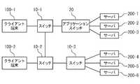
図1は、アプリケーションスイッチを利用したサーバ負荷分散処理を行う従来システムを示したものである。図1に示す従来システムは、クライアント端末100(100−i、i=1〜N:Nは任意の整数)と、スイッチ10(10−i、i=1〜N)と、アプリケーションスイッチ20と、サーバ200(200−i、i=1〜N)を含む。 FIG. 1 shows a conventional system that performs server load distribution processing using an application switch. A conventional system shown in FIG. 1 includes a client terminal 100 (100-i, i = 1 to N: N is an arbitrary integer), a switch 10 (10-i, i = 1 to N), an
ここでは、クライアント端末100として、クライアント端末100−1〜100−2を示す。スイッチ10として、スイッチ10−1〜10−3を示す。サーバ200として、サーバ200−1〜200−6を示す。なお、サーバ200−1〜200−3は、アプリケーションスイッチ20に接続されており、サーバ200−4〜200−6は、スイッチ10−3に接続されている。 Here, client terminals 100-1 to 100-2 are shown as the client terminal 100. As the
図1に示す従来システムでは、クライアント端末100からのアクセスがスイッチ10及びアプリケーションスイッチ20を経由してサーバ200に接続される際に、アプリケーションスイッチ20にて、アプリケーションレイヤのメッセージを解釈し、サーバ200−1〜200−6の中から実際のアクセス対象となるサーバを選択して、中継接続を行う。 In the conventional system shown in FIG. 1, when an access from the client terminal 100 is connected to the server 200 via the
図1に示す従来システムにおける課題について説明する。図1に示す従来システムは、典型的には、サーバ200−1〜200−3がアプリケーションスイッチ20に近い所(アプリケーションスイッチ側)に設けられるため、アプリケーションスイッチ20でスイッチ判定を行った後に、サーバ200−1〜200−3のいずれかを選択した場合において、ネットワークトラヒック(通信量)が非効率になることはない。 Problems in the conventional system shown in FIG. 1 will be described. In the conventional system shown in FIG. 1, the servers 200-1 to 200-3 are typically provided near the application switch 20 (on the application switch side). When any one of 200-1 to 200-3 is selected, the network traffic (communication amount) does not become inefficient.
しかしながら、サーバの配備が広域になる場合や、VM(Virtual Machine)と呼ばれる仮想マシンの利用によって、サーバの物理位置が移動する場合が考えられる。 However, it is conceivable that the server is located in a wide area, or the physical position of the server is moved by using a virtual machine called VM (Virtual Machine).
例えば、図1に示す従来システムにおいて、クライアント端末100−1からのアクセスがアプリケーションスイッチ20を経由してサーバ200−6に接続される場合、ネットワークの経路は、スイッチ10−1、アプリケーションスイッチ20、スイッチ10−1、スイッチ10−2、スイッチ10−3、そしてサーバ200−6となる。 For example, in the conventional system shown in FIG. 1, when the access from the client terminal 100-1 is connected to the server 200-6 via the
このように、図1に示すような従来システムでは、アプリケーションスイッチを利用してスイッチ処理を行うと、ネットワーク経路が非効率になるという課題がある。 As described above, the conventional system as shown in FIG. 1 has a problem that the network path becomes inefficient when the switch process is performed using the application switch.
特許文献2に示される手法は、TCPスプライシング処理において、アプリケーションスイッチにおける振り分け判断部をバックエンドノードに配備したものである。これにより、アプリケーションスイッチでの判断処理の負荷を分散することができる。しかしながら、この方式では、TCPスプライシングを行うフロントエンド処理が複数のバックエンドノードへの経路上にある必要があり、サーバが広域に分散した場合に中継処理が非効率になるという課題がある。 In the technique disclosed in Patent Document 2, a distribution determination unit in an application switch is provided in a back-end node in TCP splicing processing. Thereby, it is possible to distribute the load of determination processing in the application switch. However, in this method, there is a problem that the front-end processing for performing TCP splicing needs to be on a route to a plurality of back-end nodes, and relay processing becomes inefficient when servers are distributed over a wide area.
すなわち、バックエンドノードが広域に分散した場合であっても、クライアントからサーバへのトラヒックは、フロントエンドノードを必ず通過するため、クライアントとサーバのネットワーク上の距離に関係なく経路が固定されてしまうという課題がある。 In other words, even if the back-end nodes are distributed over a wide area, the traffic from the client to the server always passes through the front-end node, so the route is fixed regardless of the distance between the client and the server on the network. There is a problem.
本発明の目的は、アプリケーション中継処理を効率的に行う方法を提供し、アプリケーションスイッチでの振り分け対象が広域に分散された場合において、単一の中継ノードを経由することなく最適な中継ノードを選択し、効率的なネットワーク収容を実現することを提供することである。 An object of the present invention is to provide a method for efficiently performing application relay processing, and when an object to be distributed by an application switch is distributed over a wide area, an optimum relay node is selected without going through a single relay node. And providing efficient network accommodation.
本発明のアプリケーションスイッチシステムは、ネットワーク上に存在する複数のクライアント端末と複数のサーバとの接続を制御するスイッチと、プロトコル中継を行う中継装置と、コントローラとを含む。コントローラは、スイッチ内の転送先を決定する経路テーブルを集中制御する手段と、中継装置の中継処理の制御を行う手段と、複数のサーバのうち接続先となるサーバの選択を行う手段と、複数のクライアント端末のうちの1つのクライアントと選択されたサーバとの間を結び、中継装置を含む経路を選択し、選択された経路をスイッチ内の経路テーブルに設定する手段と、中継装置がプロトコル中継を行う際に用いられる中継情報を、中継装置に設定する手段とを具備する。 The application switch system of the present invention includes a switch that controls connection between a plurality of client terminals and a plurality of servers existing on a network, a relay device that performs protocol relay, and a controller. The controller includes means for centrally controlling a routing table for determining a transfer destination in the switch, means for controlling relay processing of the relay device, means for selecting a server to be a connection destination among a plurality of servers, Means for connecting a client of one of the client terminals and the selected server, selecting a route including the relay device, and setting the selected route in the route table in the switch, and the relay device relaying the protocol Means for setting the relay information used in performing the relay to the relay device.
また、本発明の他のアプリケーションスイッチシステムは、ネットワーク上に存在する複数のクライアント端末と複数のサーバとの接続を制御するスイッチと、プロトコル中継を行う中継装置と、コントローラとを含む。コントローラは、スイッチ内の転送先を決定する経路テーブルを集中制御する手段と、中継装置の中継処理の制御を行う手段と、複数のサーバのうち接続先の候補となるサーバ群を判定する手段と、複数のクライアント端末のうちの1つのクライアントと接続先候補の各サーバとの間を結び、複数のサーバ群への中継処理を行う中継装置を選択する手段と、中継装置を含む経路を選択し、選択された経路をスイッチ内の経路テーブルに設定する手段と、中継装置がプロトコル中継を行う際に用いられる中継情報を、中継装置に設定する手段とを具備する。 Another application switch system according to the present invention includes a switch that controls connection between a plurality of client terminals and a plurality of servers existing on a network, a relay device that performs protocol relay, and a controller. A controller for centrally controlling a routing table for determining a transfer destination in the switch; means for controlling relay processing of a relay device; and means for determining a server group that is a candidate for a connection destination among a plurality of servers; Selecting a relay device that connects a client of a plurality of client terminals and each connection destination candidate server and performs a relay process to a plurality of server groups, and selects a route including the relay device. Means for setting the selected route in the route table in the switch, and means for setting the relay information used when the relay device performs protocol relay in the relay device.
本発明のアプリケーションスイッチ方法では、スイッチにより、ネットワーク上に存在する複数のクライアント端末と複数のサーバとの接続を制御する。次に、中継装置により、プロトコル中継を行う。次に、コントローラにより、スイッチ内の転送先を決定する経路テーブルを集中制御する。次に、コントローラにより、中継装置の中継処理の制御を行う。次に、コントローラにより、複数のサーバのうち接続先となるサーバの選択を行う。次に、コントローラにより、複数のクライアント端末のうちの1つのクライアントと選択されたサーバとの間を結び、中継装置を含む経路を選択する。次に、コントローラにより、選択された経路をスイッチ内の経路テーブルに設定する。次に、コントローラにより、中継装置がプロトコル中継を行う際に用いられる中継情報を、中継装置に設定する。 In the application switch method of the present invention, the switch controls connection between a plurality of client terminals and a plurality of servers existing on the network. Next, protocol relay is performed by the relay device. Next, the controller centrally controls the route table for determining the transfer destination in the switch. Next, the relay process of the relay device is controlled by the controller. Next, the server selects a connection destination server from among the plurality of servers. Next, the controller connects one client of the plurality of client terminals and the selected server, and selects a route including the relay device. Next, the selected route is set in the route table in the switch by the controller. Next, the relay information used when the relay device performs protocol relay is set in the relay device by the controller.
本発明に係るプログラムを実行することにより、コンピュータは以下の動作を行う。まず、当該コンピュータは、複数のサーバ、スイッチ、及び中継装置を、コンピュータ上の仮想マシンのアプリケーションとして動作させる。また、スイッチにより、ネットワーク上に存在する複数のクライアント端末と複数のサーバとの接続を制御する。また、中継装置により、プロトコル中継を行う。また、スイッチ内の転送先を決定する経路テーブルを集中制御する。また、中継装置の中継処理の制御を行う。また、複数のサーバのうち接続先となるサーバの選択を行う。また、複数のクライアント端末のうちの1つのクライアントと選択されたサーバとの間を結び、中継装置を含む経路を選択する。また、選択された経路をスイッチ内の経路テーブルに設定する。また、中継装置がプロトコル中継を行う際に用いられる中継情報を、中継装置に設定する。なお、本発明に係るプログラムは、記憶媒体や記憶装置に格納可能である。 By executing the program according to the present invention, the computer performs the following operations. First, the computer causes a plurality of servers, switches, and relay devices to operate as virtual machine applications on the computer. The switch controls connections between a plurality of client terminals and a plurality of servers existing on the network. Also, protocol relay is performed by the relay device. In addition, centralized control is performed on a route table for determining a transfer destination in the switch. It also controls relay processing of the relay device. In addition, a server to be a connection destination among a plurality of servers is selected. In addition, a route including one of the plurality of client terminals is connected to the selected server and the relay device is selected. The selected route is set in the route table in the switch. Also, relay information used when the relay device performs protocol relay is set in the relay device. The program according to the present invention can be stored in a storage medium or a storage device.
これにより、アプリケーションスイッチ処理において、スイッチ判定処理を行う装置と中継を行う装置を分離し、任意の位置にTCPの中継ノードを配備することを可能にして、クライアントとサーバ間のネットワーク経路の最適化を実現する。 As a result, in application switch processing, it is possible to separate a device that performs switch determination processing from a device that performs relay, and to deploy a TCP relay node at an arbitrary position, thereby optimizing the network path between the client and server Is realized.
<第1実施形態>
以下に、本発明の第1実施形態について添付図面を参照して説明する。
図2に示すように、本発明のアプリケーションスイッチシステムは、クライアント端末100(100−i、i=1〜N:Nは任意の整数)と、スイッチ10(10−i、i=1〜N)と、中継装置30と、制御回線50と、コントローラ60と、サーバ200(200−i、i=1〜N)を含む。<First Embodiment>
Hereinafter, a first embodiment of the present invention will be described with reference to the accompanying drawings.
As shown in FIG. 2, the application switch system of the present invention includes a client terminal 100 (100-i, i = 1 to N: N is an arbitrary integer) and a switch 10 (10-i, i = 1 to N). A
クライアント端末100は、スイッチ10及び中継装置30を経由して、サーバ200に接続する。スイッチ10及び中継装置30は、ネットワーク上に存在している。ここでは、クライアント端末100、スイッチ10、中継装置30、及びサーバ200の個数は異なっているものとする。但し、実際には、クライアント端末100、スイッチ10、中継装置30、及びサーバ200の個数は同じでも良い。 The client terminal 100 is connected to the server 200 via the
スイッチ10は、アプリケーションスイッチである。 The
中継装置30は、クライアント端末100とサーバ200との間の転送データを、TCP(Transmission Control Protocol)スプライシング処理により中継する。 The
コントローラ60は、制御回線50を介して、スイッチ10及び中継装置30に接続し、スイッチ10及び中継装置30を集中的に管理する。 The
コントローラ60は、制御インタフェース61と、中継制御部62と、経路制御部63を備える。 The
制御インタフェース61は、制御回線50を介して、スイッチ10や、中継装置30と接続する。 The
中継制御部62は、アプリケーション振り分け判定を行う。また、中継制御部62は、中継装置30に対する制御(中継制御)を行う。ここでは、中継制御部62は、中継装置30に対して、ハンドオフ処理を行う。例えば、中継制御部62は、中継装置30に対して、中継開始指示を行う。中継装置30は、中継開始指示に応じて、中継処理を開始する。 The
経路制御部63は、ネットワーク経路を集中管理する。また、経路制御部63は、接続元のクライアント端末100からサーバ200までの経路を計算し、その経路上にある中継装置30の一つを選択する。ここでは、経路制御部63は、中継制御部62がアプリケーション振り分け先を判定した後、振り分け先のサーバに最も近い中継装置30を選択するとともに、選択された中継装置30までの経路を設定する。 The
これにより、コントローラ60は、広域に分散配備された任意のサーバに対する振り分け選択と、その際の最適なネットワーク経路の選択、中継位置の選択を行うことで、ネットワーク経路の最適化を行う。 As a result, the
クライアント端末100の例として、PC(パソコン)、モバイルノートPC、シンクライアント端末、ワークステーション、携帯電話機、カーナビ(カーナビゲーションシステム)、携帯ゲーム機、家庭用ゲーム機、双方向テレビ、デジタルチューナー、デジタルレコーダー、情報家電(information home appliance)、OA(Office Automation)機器等が考えられる。クライアント端末100は、車両や船舶、航空機等の移動体に搭載されていても良い。但し、実際には、これらの例に限定されない。 Examples of the client terminal 100 include a PC (personal computer), a mobile notebook PC, a thin client terminal, a workstation, a mobile phone, a car navigation system (car navigation system), a portable game machine, a home game machine, an interactive TV, a digital tuner, a digital A recorder, an information home appliance, an OA (Office Automation) device, etc. can be considered. The client terminal 100 may be mounted on a moving body such as a vehicle, a ship, or an aircraft. However, actually, it is not limited to these examples.
スイッチ10及び中継装置30が属するネットワーク上の通信回線や、制御回線50の例として、インターネット、LAN(Local Area Network)、無線LAN(Wireless LAN)、WAN(Wide Area Network)、バックボーン(Backbone)、ケーブルテレビ(CATV)回線、固定電話網、携帯電話網、WiMAX(IEEE 802.16a)、3G(3rd Generation)、専用線(lease line)、IrDA(Infrared Data Association)、Bluetooth(登録商標)、シリアル通信回線、データバス等が考えられる。但し、実際には、これらの例に限定されない。 Examples of the communication line on the network to which the
コントローラ60やサーバ200の例として、PC(パソコン)、シンクライアントサーバ、ワークステーション、メインフレーム、スーパーコンピュータ等の計算機が考えられる。但し、実際には、これらの例に限定されない。 As examples of the
クライアント端末100からサーバ200へのコネクション接続の際の各装置の機能について、図2に示すようなアプリケーションスイッチシステムにおいて、クライアント端末100−1から所定のサービスに対して接続する場合を例に説明する。 The function of each device at the time of connection connection from the client terminal 100 to the server 200 will be described by taking as an example a case where the client terminal 100-1 connects to a predetermined service in the application switch system as shown in FIG. .
クライアント端末100−1は、コントローラ60に対して、TCP接続要求を行う。ここでは、クライアント端末100−1は、コントローラ60を宛先としたパケットを送信し、TCP接続を試みる。このとき、端末100−1からみると、コントローラ60がサーバ200にみえる。すなわち、端末100−1は、コントローラ60をサーバ200とみなしている。 The client terminal 100-1 makes a TCP connection request to the
スイッチ10−1は、クライアント端末100−1から送信されたパケットを受信すると、スイッチ10のフローエントリーに基づいて、転送処理を行う。 When the switch 10-1 receives the packet transmitted from the client terminal 100-1, the switch 10-1 performs a transfer process based on the flow entry of the
スイッチ10−1は、初期状態でフローエントリーが登録されていない場合、制御回線50を通じて、クライアント端末100−1から送信されたパケットをコントローラ60に送る。 When the flow entry is not registered in the initial state, the switch 10-1 transmits the packet transmitted from the client terminal 100-1 to the
コントローラ60は、クライアント端末100−1からのTCP接続要求に対して、TCPプロトコルスタックで処理を行う。なお、コントローラ60も、クライアント端末100−1宛のパケットを送信する際は、スイッチ10−1を経由して送信する。 The
コントローラ60は、クライアント端末100−1からの送信データの内容に基づいて、接続すべき(アクセス対象の)サーバ200を選択する。選択判断としては、サーバ200の負荷を平滑化する方法や、クライアント端末100−1にネットワーク的に近いものを選択する方法等がある。 The
コントローラ60は、サーバ200を選択した後、コントローラ60とサーバ200の間に第2のTCPコネクションを接続する。 After selecting the server 200, the
更に、コントローラ60は、クライアント端末100−1とサーバ200間の経路上にある中継装置30、若しくは、経路に近い位置にある中継装置30を選択し、第1のTCP情報及び第2のTCP情報を使用してスプライシング処理を実行する。これにより、クライアント端末100−1とサーバ200間のアクセス処理が、コントローラ60経由のプロキシ処理から、中継処理を経由するパケット中継処理になる。 Further, the
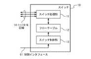
図3を参照して、本発明の第1実施形態におけるスイッチ10の構成について説明する。
スイッチ10は、スイッチ処理部11と、フローテーブル12と、スイッチ制御部13と、回線14(14−i、i=1〜N)を備える。With reference to FIG. 3, the structure of the
The
スイッチ処理部11は、回線14から入力されたパケットのヘッダ情報を抽出し、フローテーブル12を参照して、出力回線を決定する。また、スイッチ処理部11は、回線14を介して、クライアント端末100、他のスイッチ10、中継装置30、及びサーバ200に接続する。ここでは、スイッチ処理部11は、回線14(14−i、i=1〜N)から入力されたパケットに対し、ヘッダ情報を抽出し、フローテーブル12を参照して、出力回線を決定する。 The
フローテーブル12は、MAC(Media Access Control)ヘッダ、IP(Internet Protocol)ヘッダ、レイヤ4ヘッダから得られる情報をフローの識別情報として登録し、そのフローに対する出力情報を格納するエントリを有する。フローに対する出力情報の例として、出力回線やヘッダ書き換え等のアクション情報が考えられる。ここでは、フローテーブル12は、IPアドレス、TCPポート番号にて特定されるフロー情報や、その他のラベル等、フローの識別子となるものに基づいていれば良い。 The flow table 12 has an entry for registering information obtained from a MAC (Media Access Control) header, an IP (Internet Protocol) header, and a layer 4 header as flow identification information and storing output information for the flow. As an example of output information for a flow, action information such as an output line and header rewriting can be considered. Here, the flow table 12 may be based on a flow identifier such as flow information specified by an IP address and a TCP port number, and other labels.
スイッチ制御部13は、制御インタフェース61を介して、コントローラ60に接続する。このとき、スイッチ制御部13は、制御回線50を経由して、制御インタフェース61に接続する。すなわち、スイッチ制御部13は、制御回線50を介して、コントローラ60からの指示や操作、その他のデータを受け付ける。ここでは、スイッチ制御部13は、コントローラ60との間の制御通信を行うとともに、スイッチ10の内部の制御を行う。コントローラ60は、スイッチ制御部13を介して、フローエントリーの登録、削除等の制御を行う。また、スイッチ制御部13は、フローエントリーにヒットしないパケットについて、制御インタフェースを介してコントローラ60に送信したり、コントローラ60からのパケット送信命令により、指定された出力回線への送信処理を行う。 The
回線14(14−i、i=1〜N)は、クライアント端末100、他のスイッチ10、中継装置30、及びサーバ200等に接続される通信回線である。 A line 14 (14-i, i = 1 to N) is a communication line connected to the client terminal 100, another
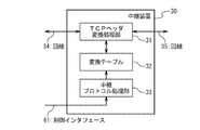
図4を参照して、本発明の第1実施形態における中継装置30の構成について説明する。
中継装置30は、TCPヘッダ変換処理部31と、変換テーブル32と、中継プロトコル処理部33と、回線34と、回線35を備える。With reference to FIG. 4, the structure of the
The
TCPヘッダ変換処理部31は、回線34及び回線35を介して、外部と接続する。ここでは、TCPヘッダ変換処理部31は、回線34及び回線35を介して、クライアント端末100、他のスイッチ10、中継装置30、及びサーバ200に接続する。また、TCPヘッダ変換処理部31は、変換テーブル32に基づいて、回線34と回線35の間で送受信されるパケットに対して、TCPヘッダ変換処理を行う。ここでは、TCPヘッダ変換処理部31は、回線34又は回線35から受信したパケットに対し、変換テーブル32を参照し、受信したパケットのヘッダが、変換テーブル32に記載されているヘッダにヒットした場合は、受信したパケットのヘッダを変換テーブル32に記載されているヘッダに置き換えるヘッダ変換処理を行う。 The TCP header
変換テーブル32には、TCPスプライシング処理に必要な情報が記載されている。ここでは、変換テーブル32は、エントリとして、入力キーと、出力情報と、ステート情報を有する。TCPヘッダ変換処理部31は、変換テーブル32を参照し、IPアドレス及びTCPポート番号を入力キーとして検索して、IPアドレス及びTCPポート番号の書き換え値と、シーケンス番号の再計算のための補正値を取得する。 The conversion table 32 describes information necessary for TCP splicing processing. Here, the conversion table 32 has an input key, output information, and state information as entries. The TCP header
中継プロトコル処理部33は、制御インタフェース61を介して、コントローラ60に接続する。このとき、中継プロトコル処理部33は、制御回線50を経由して、制御インタフェース61に接続する。すなわち、中継プロトコル処理部33は、制御回線50を介して、コントローラ60からの指示や操作、その他のデータを受け付ける。ここでは、中継プロトコル処理部33は、コントローラ60からのハンドオフ要求命令や、中継開始指示等の中継制御に関するプロトコル処理を行う。このとき、中継プロトコル処理部33は、ハンドオフ命令に応じて、TCPスプライシング処理に必要な変換テーブル32の設定を行う。また、中継プロトコル処理部33は、中継開始指示に応じて、該当フローに対するスプライシング処理を有効にするとともに、バッファに保留されていたパケットの送信を行う。 The relay
回線34及び回線35は、クライアント端末100、他のスイッチ10、中継装置30、及びサーバ200等に接続される通信回線である。 The
なお、中継装置30は、スイッチ機能を兼ね備えても良いが、ここでは、特に本発明による中継処理機能を備えたものを中継装置30と呼び、中継処理機能を備えない回線スイッチをスイッチ10と呼ぶことで、スイッチ10と中継装置30を区別している。 The
図5を参照して、変換テーブル32内のエントリの例について説明する。 An example of entries in the conversion table 32 will be described with reference to FIG.
変換テーブル32は、入力キーとして、回線番号と、IP宛先アドレス(IPDA:IP Destination Address)と、IP送信元アドレス(IPSA:IP Source Address)と、TCP送信元ポート番号(TCPSP:TCP Source Port)と、TCP宛先ポート番号(TCPDP:TCP Destination Port)を含む。TCPヘッダ変換処理部31は、変換テーブル32を参照し、受信したパケットのヘッダと、これらの入力キーを照合することで、エントリがあるかどうかの判定を行う。 The conversion table 32 includes, as input keys, a line number, an IP destination address (IPDA), an IP source address (IPSA), and a TCP source port number (TCPSP). And a TCP destination port number (TCPDP: TCP Destination Port). The TCP header
変換テーブル32の出力情報には、ヘッダを変換して出力するための情報が記載されている。ここでは、変換テーブル32は、出力情報として、出力回線番号と、IP宛先アドレス(IPDA)、IP送信元アドレス(IPSA)、TCP送信元ポート番号(TCPSP)、TCP宛先ポート番号(TCPDP)と、シーケンス番号の差分値と、ACK番号の差分値を含む。TCPヘッダ変換処理部31は、変換テーブル32を参照し、IP宛先アドレス(IPDA)、IP送信元アドレス(IPSA)、TCP送信元ポート番号(TCPSP)、及びTCP宛先ポート番号(TCPDP)は、出力パケットに付与する。また、シーケンス番号の差分値とACK番号の差分値は、TCPスプライシング処理のために記録されている。 In the output information of the conversion table 32, information for converting and outputting the header is described. Here, the conversion table 32 includes, as output information, an output line number, an IP destination address (IPDA), an IP source address (IPSA), a TCP source port number (TCPSP), a TCP destination port number (TCPDP), It includes the difference value of the sequence number and the difference value of the ACK number. The TCP header
また、変換テーブル32は、ステート情報として、フロー管理情報を含む。ここでは、TCPヘッダ変換処理部31は、変換テーブル32に、フロー管理情報としてTCPの状態を記録する。 The conversion table 32 includes flow management information as state information. Here, the TCP header
なお、スイッチ10及び中継装置30は、CPU(Central Processing Unit)上で動作するプログラムとして実現されても良い。また、スイッチ10及び中継装置30は、ハードウェア回路として実現されても良い。 Note that the
図6Aを参照して、コントローラ60の処理について説明する。なお、図6Aでは、コントローラ60の処理のうち、本発明に関係する箇所のみを示している。 With reference to FIG. 6A, the processing of the
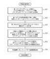
(1)ステップS11
コントローラ60は、外部からのパケット入力等のトリガにより、イベント処理を起動する。(1) Step S11
The
(2)ステップS12
コントローラ60は、イベント処理にてイベントの種類を判断する。ここでは、コントローラ60は、イベントがクライアント端末100とコントローラ60との間における第1のTCPコネクション確立イベントであるか否か判断する。(2) Step S12
The
(3)ステップS13
コントローラ60は、イベントが第1のTCPコネクション確立イベントである場合、中継処理初期化処理を行う。コントローラ60は、中継処理初期化処理において、第1のTCPコネクションに対する中断設定を行った後、接続先となるサーバ200との間に第2のTCPコネクションを確立する。また、コントローラ60は、接続元のクライアント端末100から接続先となるサーバ200までの経路を計算し、その経路上にある中継装置30の一つを選択し、選択された中継装置30に対して、第1及び第2のTCPコネクション情報に基づいて、ハンドオフ処理要求を送信する。中継処理初期化処理の詳細については後述する。コントローラ60は、中継処理初期化処理の後、再びイベント処理に戻る。(3) Step S13
When the event is the first TCP connection establishment event, the
(4)ステップS14
コントローラ60は、イベントがハンドオフ処理完了であるか否か判断する。(4) Step S14
The
(5)ステップS15
コントローラ60は、イベントがハンドオフ処理完了であった場合、中継処理初期化処理において決定した経路上の各スイッチ10に対して、フローエントリー設定を行う。フローエントリーは、第1及び第2のTCPフロー情報を表している。クライアント端末100と中継装置30の間のスイッチ10には、第1のTCP情報を設定する。中継装置30とサーバ200の間のスイッチ10には、第2のTCP情報を設定する。(5) Step S15
When the event is the handoff process completion, the
(6)ステップS16
コントローラ60は、イベントがフローエントリー設定完了であるか否か判断する。(6) Step S16
The
(7)ステップS17
コントローラ60は、イベントがフローエントリー設定完了であった場合、中継処理初期化処理で中断設定されたTCPコネクションのパケットを受信していた場合、そのパケットを中継装置30に向けて送信する。このとき、コントローラ60は、中断設定されたTCPコネクションのパケットを中継装置30に送るために、コントローラ60からスイッチ10に対してパケット送信を行い、パケット送信処理がフローエントリーを参照することで、中継装置30に向けたパケット送信が実現できる。(7) Step S17
If the event is a flow entry setting completion, or if a packet of a TCP connection suspended by the relay process initialization process has been received, the
(8)ステップS18
コントローラ60は、パケット送信と同時、又はその後遅滞無く、中継装置30に中継開始要求を送信する。(8) Step S18
The
(9)ステップS19
コントローラ60は、イベントがセッション終了通知であるか否か判断する。(9) Step S19
The
(10)ステップS20
コントローラ60は、イベントがセッション終了通知であった場合、中継のために管理していた第1及び第2のTCPに関する管理テーブルを削除する。(10) Step S20
When the event is a session end notification, the
図6Bを参照して、中継処理初期化処理の詳細について説明する。 Details of the relay process initialization process will be described with reference to FIG. 6B.
(1)ステップS21
コントローラ60の制御インタフェース61は、中継処理初期化処理では、クライアント端末100との間に第1のTCPコネクションを確立した後、クライアント端末100からデータを読み出す。更に、コントローラ60は、第1のTCPコネクションに関するコネクション情報(宛先、送信元IPアドレス、宛先、送信元TCPポート番号、シーケンス番号の初期値)をTCP処理スタックから読み出す。(1) Step S21
In the relay process initialization process, the
(2)ステップS22
コントローラ60の制御インタフェース61は、クライアント端末100からデータを読み出すと、第1のTCPコネクションの終端処理を中断し、以降に受信した同じTCPコネクションのパケットを、受信したままの状態でバッファリングして保持しておく。(2) Step S22
When data is read from the client terminal 100, the
(3)ステップS23
コントローラ60の中継制御部62は、読み出されたデータの内容をチェックして、設定ポリシーと照合し、接続先となるサーバ200を決定する。(3) Step S23
The
(4)ステップS24
コントローラ60の制御インタフェース61は、決定したサーバ200(接続先となるサーバ200)との間に第2のTCPコネクションを確立する。このとき、コントローラ60は、第2のTCPのコネクション情報をTCP処理スタックから読み出す。第2のTCPのコネクション情報の例として、宛先、送信元IPアドレス、宛先、送信元TCPポート番号、シーケンス番号の初期値等が考えられる。更に、コントローラ60は、第1のTCPコネクションにてクライアント端末100から読み出されたデータを、第2のTCPコネクションにて接続先となるサーバ200に送信する。(4) Step S24
The
(5)ステップS25
コントローラ60の経路制御部63は、接続元のクライアント端末100から接続先となるサーバ200までの経路を計算し、その経路上にある中継装置30の一つを選択する。中継装置30の選択方法としては、最もサーバ200に近い中継装置30や最もクライアント端末100に近い中継装置30、或いは、中継可能なコネクション数に最も余裕のある中継装置30を選択する方法が考えられる。(5) Step S25
The path control
(6)ステップS26
コントローラ60の中継制御部62は、選択された中継装置30に対して、第1及び第2のTCPコネクション情報に基づいて、ハンドオフ処理要求を送信する。コントローラ60は、第1及び第2のコネクション情報の例としては、クライアント端末100のIPアドレス、コントローラ60のIPアドレス、サーバ200のIPアドレス、TCPコネクションのポート番号、シーケンス番号の差分値、及びACK番号の差分値が考えられる。シーケンス番号の差分値、及びACK番号の差分値は、シーケンス番号の初期値から求められる。コントローラ60は、これらのコネクション情報をハンドオフ処理要求として、決定した中継装置30に対して送信する。コントローラ60は、ハンドオフ処理要求を送信した後、ハンドオフ処理を完了する。(6) Step S26
The
コントローラ60からスイッチ10内のフローテーブル12を操作する具体的な方式としては、「Openflow」(http://www.openflowswitch.org/)や、「GMPLS」(Generalized Multi−Protocol Label Switching)、「MIB+VLAN」(Management Information Base + Virtual LAN)等が挙げられる。 Specific methods for operating the flow table 12 in the
「Openflow」の場合、コントローラ60内の制御インタフェース61は、「Openflow Controller」に対応する。制御回線50及びスイッチ制御部13のコントローラ60向けインタフェースは、「Secure Channel」に対応する。「GMPLS」の場合、コントローラ60は、「MIB」に該当する。スイッチ10は、「GMPLSスイッチ」に該当する。スイッチ制御部13は、「GMPLSスイッチ」内のテーブル管理部に該当する。また、コントローラ60は、スイッチ10の「MIBインタフェース」を用いて、スイッチ10の「VLAN設定」を操作することもできる。 In the case of “Openflow”, the
コントローラ60内の制御インタフェース61と、スイッチ10内のスイッチ制御部13の間のインタフェースが、「Openflow」、「GMPLS」、「MIB+VLAN」のいずれに対応している場合においても、本実施形態を適用できる。 This embodiment is applied even when the interface between the
<第2実施形態>
以下に、本発明の第2実施形態について説明する。
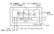
本実施形態では、中継装置30及びサーバ200を単独の装置としてではなく、コンピュータ上の仮想マシン(VM)のアプリケーションとして実現する。サーバ200上に複数の仮想マシンを動作させ、これらの仮想マシンの一つは、中継機能を実現する。他の仮想マシンは、サーバ機能を実現する。そして、サーバ200上で、中継機能とサーバ機能との間を仮想マシン間の内部ネットワークにより接続する。Second Embodiment
The second embodiment of the present invention will be described below.
In the present embodiment, the
図7を参照すると、本実施形態においては、サーバ200は、主機能部210と、サーバ機能部220(220−i、i=1〜N)と、中継機能部230を含む。 Referring to FIG. 7, in this embodiment, the server 200 includes a
主機能部210は、CPU211と、仮想マシンモニタ(VMM(Virtual Machine Monitor)、又は、Hypervisor)212を含む。主機能部210では、CPU211上に仮想マシンモニタ212が動作し、その上で、サーバ機能部220−1〜220−N、中継機能部230が動作している。ここでは、中継機能部230は、中継機能と、スイッチ機能を持つ。 The
更に、中継機能部230とサーバ機能部220の間は、通信チャネルで通信可能である。中継機能部230は、装置の外部との間にネットワークインタフェースと制御インタフェースを保持する。なお、制御インタフェースとネットワークインタフェースは、物理的に同じ回線を使用しても良い。 Further, the relay function unit 230 and the server function unit 220 can communicate via a communication channel. The relay function unit 230 holds a network interface and a control interface with the outside of the apparatus. The control interface and the network interface may use the same physical line.
本構成では、サーバ200とスイッチ10、中継機能部230が1つのコンピュータ上で動作することで、中継機能部230を最もサーバ200に近づけた場合の構成となる。中継装置30を物理的な装置としてネットワーク内に配備した場合では、中継のための変換テーブル32の位置がネットワークの経路上にあり、その位置が変更できないが、本例に示す配備例では、中継機能部230が物理的には、サーバ200と同じ位置にあり、ネットワーク上に変換テーブル32が配備されないため、ネットワーク経路を柔軟に選択することができる。また、中継機能部230を仮想マシン上に実現することで、中継機能部230がサーバ200と同じ計算機に配備されているにもかかわらず、サーバ200プリケーションやサーバ200のプロトコルスタックは、変更が不要であり、ポータビリティが向上するという効果がある。 In this configuration, the server 200, the
<実施例1>
図8を参照して、図2におけるクライアント端末100−1からサーバ200−3に対して接続する場合について説明する。<Example 1>
With reference to FIG. 8, the case where the client terminal 100-1 in FIG. 2 connects to the server 200-3 will be described.
(1)ステップS101
クライアント端末100−1は、サーバ200が提供するサービスを受けるために、TCP接続要求を出す。このとき、スイッチ10−1の初期状態は、フローエントリーがない状態である。従って、フロー検索でミスヒットとなり、コントローラ60に対してデータが送られる。また、コントローラ60は、スイッチ10−1を介して、このクライアント端末100−1と通信することができる。TCP接続要求では、「3−way handshake」と呼ばれるシーケンスでコネクションが確立される。(1) Step S101
The client terminal 100-1 issues a TCP connection request in order to receive a service provided by the server 200. At this time, the initial state of the switch 10-1 is a state where there is no flow entry. Accordingly, the flow search results in a miss hit, and data is sent to the
(2)ステップS102
クライアント端末100−1は、コネクションが確立すると、リクエストデータをコントローラ60に送信する。(2) Step S102
When the connection is established, the client terminal 100-1 transmits request data to the
(3)ステップS103
コントローラ60は、データセグメントを正しく受信すると、TCPプロトコル処理を行い、受け取ったデータのシーケンス番号を示す位置についてのACKを返す。(3) Step S103
When the data segment is correctly received, the
(4)ステップS104
コントローラ60は、リクエストデータの内容をチェックして、その内容に基づいて、接続するサーバ200を選択する。例えば、コントローラ60は、HTTPの場合には、GETメッセージに含まれるURI(Uniform Resource Identifier)を中継制御部62に含まれるポリシーデータベースと比較することで、どのサーバ200に接続するかを判定し、判定結果に基づいて、接続するサーバ200を選択する。ここでは、コントローラ60は、サーバ200−3を選択し、選択されたサーバ200に対して第二のTCPセッションを確立する。(4) Step S104
The
(5)ステップS105
コントローラ60は、クライアント端末100−1から受信して保持していたリクエストデータをサーバ200−3に対して送信する。このとき、コントローラ60は、選択されたサーバ200−3が接続されたエッジとなるスイッチ10−3を介してデータを送信する。(5) Step S105
The
(6)ステップS106
サーバ200−3は、リクエストデータに対してACKを返すことで、正常受信を通知する。このとき、サーバ200−3は、スイッチ10−3においてフローエントリーを検索し、ミスヒットである場合に制御回線を使って、戻りパケットをコントローラ60に送る。(6) Step S106
The server 200-3 notifies normal reception by returning ACK to the request data. At this time, the server 200-3 searches the flow entry in the switch 10-3, and sends a return packet to the
(7)ステップS107
コントローラ60は、サーバ200−3からACKを受信すると、TCP終端処理を中断し、クライアント端末100−1から受信するデータがある場合、パケットのままバッファに保持する。(7) Step S107
When receiving an ACK from the server 200-3, the
(8)ステップS108
同様に、コントローラ60は、サーバ200−3からACKを受信すると、TCP終端処理を中断し、サーバ200−3から受信するデータがある場合、パケットのままバッファに保持する。(8) Step S108
Similarly, when receiving an ACK from the server 200-3, the
(9)ステップS109
次に、コントローラ60は、経路制御部63にクライアント端末100−1からサーバ200−3までの経路を問い合わせ、TCPスプライシングを行う中継装置30を決定する。いま、図2において、コントローラ60は、クライアント端末100−1からサーバ200−3へのアクセスを選択したとし、経路としてスイッチ10−1、スイッチ10−2、中継装置30−1、スイッチ10−3を取得したとする。ここでは、コントローラ60は、中継装置30−1を利用すると決定する。コントローラ60は、中継装置30−1に対して、TCPスプライシングのためのハンドオフ要求を送信する。ハンドオフ要求には、第一及び第二のTCPの情報が含まれる。具体的には、TCPセッションを特定するための、IPアドレス(宛先、送信元)、TCPポート番号(宛先、送信元)と第一と第二のTCPにおける初期シーケンス番号の差分情報であり、シーケンス番号の差分情報は、クライアント端末100−1からサーバ200−3の方向と、サーバ200−3からクライアント端末100−1の方向の二種類がある。(9) Step S109
Next, the
(10)ステップS110
中継装置30−1は、ハンドオフ要求を受信すると、要求に含まれるパラメータを変換テーブル32に登録する。変換テーブル32は、入力ヘッダ情報をキーとして登録される。中継装置30−1は、変換テーブル32に、クライアント端末100−1からサーバ200−3の方向の変換ルールと、サーバ200−3からクライアント端末100−1の方向の変換ルールの2種類を登録する。この例を図5に示す。本例では、クライアント端末100−1のIPアドレス「10.2.1.1」、コントローラ60のIPアドレス「10.1.1.1」の間に第1のTCPコネクションがある。TCPの宛先ポート番号は、「80番」である。送信元ポート番号は、「1500番」である。サーバ200−3のIPアドレス「10.1.0.2」とコントローラ60との間には、第2のTCPコネクションがある。TCPの宛先ポート番号は、「80番」である。送信元ポート番号は、「2000番」である。また、中継装置30−1は、クライアント端末100−1からサーバ200−3の方向に対して第1のTCPから第2のTCPへの変換を行うために、シーケンス番号の値を「−4000」し、ACK番号の値を「+2000」する旨を、変換テーブル32に登録する。なお、検索時に方向に応じて宛先、送信元のアドレス、ポート番号を入れ替えるようにすれば、テーブルのエントリは、1種類で良い。中継装置30−1は、変換テーブル32の登録が完了すると、完了通知をコントローラ60に送信する。(10) Step S110
When receiving the handoff request, the relay device 30-1 registers the parameter included in the request in the conversion table 32. The conversion table 32 is registered using the input header information as a key. The relay device 30-1 registers two types of conversion rules in the conversion table 32: a conversion rule in the direction from the client terminal 100-1 to the server 200-3 and a conversion rule in the direction from the server 200-3 to the client terminal 100-1. . An example of this is shown in FIG. In this example, there is a first TCP connection between the IP address “10.2.1.1” of the client terminal 100-1 and the IP address “10.1.1.1” of the
(11)ステップS111
コントローラ60は、クライアント端末100−1からサーバ200−3への経路上のスイッチ10にフローエントリーを登録する。フローエントリーは、入力したパケットのヘッダ情報をキーとして、どのポートに出力するかを決定するものである。ここでは、コントローラ60は、スイッチ10−2に、第1のTCPコネクションを転送するためのフローエントリーを設定する。(11) Step S111
The
(12)ステップS112
同様に、コントローラ60は、スイッチ10−1に、第1のTCPコネクションを転送するためのフローエントリーを設定する。(12) Step S112
Similarly, the
(13)ステップS113
コントローラ60は、スイッチ10−3に、第2のTCPコネクションを転送するためのフローエントリーを設定する。(13) Step S113
The
(14)ステップS114
コントローラ60は、フローエントリーが完了した時点で、第1及び第2のTCPコネクションの後続のデータがコントローラ60に保持されている場合は、後続のデータを、フローエントリーに従って、スイッチ10−1に転送する。(14) Step S114
When the subsequent data of the first and second TCP connections is held in the
(15)ステップS115
同様に、コントローラ60は、後続のデータを、フローエントリーに従って、スイッチ10−3に転送する。(15) Step S115
Similarly, the
(16)ステップS116
次に、コントローラ60は、中継装置30−1に中継開始要求を送る。(16) Step S116
Next, the
(17)ステップS117
中継装置30−1は、中継開始要求に応じて、指定されたTCPコネクションについてTCPスプライシング処理を開始する。以降、装置30−1は、クライアント端末100−1とサーバ200−3との間の転送データを、TCPスプライシング処理により中継する。具体的には、装置30−1は、IPアドレス、TCPポート番号の変換と、シーケンス番号、ACK番号の変換を行う。装置30−1は、シーケンス番号、及びACK番号に対し、テーブルに記載された差分値を加算する。装置30−1は、ヘッダ変換を終わると、TCPシーケンス番号を再計算して補正する。ここでは、サーバ200−3は、中継装置30−1を介して、クライアント端末100−1にデータを転送し、クライアント端末100−1からACKを受信する。(17) Step S117
In response to the relay start request, the relay device 30-1 starts TCP splicing processing for the designated TCP connection. Thereafter, the device 30-1 relays transfer data between the client terminal 100-1 and the server 200-3 by TCP splicing processing. Specifically, the device 30-1 performs conversion of an IP address and a TCP port number, and conversion of a sequence number and an ACK number. The device 30-1 adds the difference value described in the table to the sequence number and the ACK number. After completing the header conversion, the device 30-1 recalculates and corrects the TCP sequence number. Here, the server 200-3 transfers data to the client terminal 100-1 via the relay device 30-1, and receives ACK from the client terminal 100-1.
(18)ステップS118
また、クライアント端末100−1は、中継装置30−1を介して、サーバ200−3にデータを転送し、サーバ200−3からACKを受信する。(18) Step S118
Also, the client terminal 100-1 transfers data to the server 200-3 via the relay device 30-1, and receives ACK from the server 200-3.
(19)ステップS119
更に、サーバ200−3は、中継装置30−1を介して、クライアント端末100−1にデータを転送し、クライアント端末100−1からACKを受信する。(19) Step S119
Furthermore, the server 200-3 transfers data to the client terminal 100-1 via the relay device 30-1, and receives an ACK from the client terminal 100-1.
(20)ステップS120
中継装置30−1は、TCPスプライシング処理を実行している時には、TCPヘッダに含まれるFINフラグを監視し、コネクションの終了を判断する。具体的には、中継装置30−1は、双方向それぞれについて、FINとそれに対応するACKを受信した時に、TCP状態が終了になったと判断し、変換テーブル32を削除するとともに、コントローラ60にセッション終了を通知する。ここでは、クライアント端末100−1は、中継装置30−1を介して、サーバ200−3にFINを送信する。(20) Step S120
The relay device 30-1 monitors the FIN flag included in the TCP header and determines the end of the connection when executing the TCP splicing process. Specifically, the relay device 30-1 determines that the TCP state has ended when receiving FIN and ACK corresponding to each of the bidirectional devices, deletes the conversion table 32, and sends a session to the
(21)ステップS121
次に、サーバ200−3は、中継装置30−1を介して、クライアント端末100−1にACKを返す。(21) Step S121
Next, the server 200-3 returns an ACK to the client terminal 100-1 via the relay device 30-1.
(22)ステップS122
更に、サーバ200−3は、中継装置30−1を介して、クライアント端末100−1にFINを送信する。(22) Step S122
Furthermore, the server 200-3 transmits FIN to the client terminal 100-1 via the relay device 30-1.
(23)ステップS123
クライアント端末100−1は、中継装置30−1を介して、サーバ200−3にACKを返す。(23) Step S123
The client terminal 100-1 returns an ACK to the server 200-3 via the relay device 30-1.
(24)ステップS124
中継装置30−1は、コネクションが終了になったと判断した時、コントローラ60にセッション終了を通知する。(24) Step S124
When the relay device 30-1 determines that the connection has ended, the relay device 30-1 notifies the
<実施例2>
図9を参照して、図2におけるクライアント端末100−2からサーバ200−6に対して接続する場合について説明する。この例では、中継位置がクライアント端末側である。<Example 2>
With reference to FIG. 9, the case where it connects with the server 200-6 from the client terminal 100-2 in FIG. 2 is demonstrated. In this example, the relay position is on the client terminal side.
この場合、コントローラ60により求められる経路は、中継装置30−3、スイッチ10−4、スイッチ10−5、スイッチ10−6となる。経路上にある中継装置30は、最もクライアント端末100に近い箇所にある中継装置30−3のみである。本実施例では、この中継装置30−3をTCPスプライシング処理に利用する。 In this case, the paths required by the
なお、本実施例における構成の場合、始めのコネクション確立のデータは、中継装置30−3を通ってからスイッチ10−4に渡り、スイッチ10−4からコントローラ60に渡る。そのため、中継装置30−3やスイッチ10−4は、変換テーブル32にミスヒットしたパケットを、廃棄することなく、何もせずに通過させる。 In the case of the configuration of the present embodiment, the first connection establishment data passes through the relay device 30-3 and then to the switch 10-4, and then from the switch 10-4 to the
ステップS201からステップS224のほとんどは、図8のステップS101からステップS124と同様である。異なる点は、ステップS214である。ステップS214において、コントローラ60は、第1のコネクションに属するクライアント端末100−2からのパケットを保持していた場合に、そのパケットのヘッダ変換を行うために、スイッチ10−4ではなく、中継装置30−3に挿入し、スプライシング処理の後にスイッチ10−4に向けて送信する機能を持つ。 Most of steps S201 to S224 are the same as steps S101 to S124 in FIG. The difference is step S214. In step S214, when the
(1)ステップS201
クライアント端末100−2は、サーバ200が提供するサービスを受けるために、TCP接続要求を出す。このとき、スイッチ10−4の初期状態は、フローエントリーがない状態である。従って、フロー検索でミスヒットとなり、コントローラ60に対してデータが送られる。また、コントローラ60は、スイッチ10−4を介して、このクライアント端末100−2と通信することができる。(1) Step S201
The client terminal 100-2 issues a TCP connection request in order to receive a service provided by the server 200. At this time, the initial state of the switch 10-4 is a state where there is no flow entry. Accordingly, the flow search results in a miss hit, and data is sent to the
(2)ステップS202
クライアント端末100−2は、コネクションが確立すると、リクエストデータをコントローラ60に送信する。(2) Step S202
When the connection is established, the client terminal 100-2 transmits request data to the
(3)ステップS203
コントローラ60は、データセグメントを正しく受信すると、TCPプロトコル処理を行い、受け取ったデータのシーケンス番号を示す位置についてのACKを返す。(3) Step S203
When the data segment is correctly received, the
(4)ステップS204
コントローラ60は、リクエストデータの内容をチェックして、その内容に基づいて、接続するサーバ200を選択する。ここでは、コントローラ60は、サーバ200−6を選択し、選択されたサーバ200−6に対して第二のTCPセッションを確立する。(4) Step S204
The
(5)ステップS205
コントローラ60は、クライアント端末100−2から受信して保持していたリクエストデータをサーバ200−6に対して送信する。このとき、コントローラ60は、選択されたサーバ200−6が接続されたエッジとなるスイッチ10−6を介してデータを送信する。(5) Step S205
The
(6)ステップS206
サーバ200−6は、リクエストデータに対してACKを返すことで、正常受信を通知する。このとき、サーバ200−6は、スイッチ10−6においてフローエントリーを検索し、ミスヒットである場合に制御回線を使って、戻りパケットをコントローラ60に送る。(6) Step S206
The server 200-6 notifies normal reception by returning ACK to the request data. At this time, the server 200-6 searches the flow entry in the switch 10-6, and sends a return packet to the
(7)ステップS207
コントローラ60は、サーバ200−6からACKを受信すると、TCP終端処理を中断し、クライアント端末100−2から受信するデータがある場合、パケットのままバッファに保持する。(7) Step S207
When receiving an ACK from the server 200-6, the
(8)ステップS208
同様に、コントローラ60は、サーバ200−6からACKを受信すると、TCP終端処理を中断し、サーバ200−6から受信するデータがある場合、パケットのままバッファに保持する。(8) Step S208
Similarly, when receiving an ACK from the server 200-6, the
(9)ステップS209
次に、コントローラ60は、経路制御部63にクライアント端末100−2からサーバ200−6までの経路を問い合わせ、TCPスプライシングを行う中継装置30を決定する。ここでは、コントローラ60は、中継装置30−3を利用すると決定する。コントローラ60は、中継装置30−3に対して、TCPスプライシングのためのハンドオフ要求を送信する。ハンドオフ要求には、第一及び第二のTCPの情報が含まれる。具体的には、TCPセッションを特定するための、IPアドレス(宛先、送信元)、TCPポート番号(宛先、送信元)と第一と第二のTCPにおける初期シーケンス番号の差分情報であり、シーケンス番号の差分情報は、クライアント端末100−2からサーバ200−6の方向と、サーバ200−6からクライアント端末100−2の方向の二種類がある。(9) Step S209
Next, the
(10)ステップS210
中継装置30−3は、ハンドオフ要求を受信すると、要求に含まれるパラメータを変換テーブル32に登録する。変換テーブル32は、入力ヘッダ情報をキーとして登録される。中継装置30−3は、変換テーブル32に、クライアント端末100−2からサーバ200−6の方向の変換ルールと、サーバ200−6からクライアント端末100−2の方向の変換ルールの2種類を登録する。中継装置30−3は、変換テーブル32の登録が完了すると、完了通知をコントローラ60に送信する。(10) Step S210
When receiving the handoff request, the relay device 30-3 registers the parameter included in the request in the conversion table 32. The conversion table 32 is registered using the input header information as a key. The relay device 30-3 registers two types of conversion rules in the conversion table 32: a conversion rule in the direction from the client terminal 100-2 to the server 200-6 and a conversion rule in the direction from the server 200-6 to the client terminal 100-2. . When the registration of the conversion table 32 is completed, the relay device 30-3 transmits a completion notification to the
(11)ステップS211
コントローラ60は、クライアント端末100−2からサーバ200−6への経路上のスイッチ10に、フローエントリーを登録する。ここでは、コントローラ60は、スイッチ10−4に、第1のTCPコネクションを転送するためのフローエントリーを設定する。(11) Step S211
The
(12)ステップS212
同様に、コントローラ60は、スイッチ10−5に、第1のTCPコネクションを転送するためのフローエントリーを設定する。(12) Step S212
Similarly, the
(13)ステップS213
コントローラ60は、スイッチ10−6に、第2のTCPコネクションを転送するためのフローエントリーを設定する。(13) Step S213
The
(14)ステップS214
コントローラ60は、フローエントリーが完了した時点で、第1及び第2のTCPコネクションの後続のデータがコントローラ60に保持されている場合は、後続のデータを、フローエントリーに従って、中継装置30−3に転送する。(14) Step S214
If the
(15)ステップS215
同様に、コントローラ60は、後続のデータを、フローエントリーに従って、スイッチ10−6に転送する。(15) Step S215
Similarly, the
(16)ステップS216
次に、コントローラ60は、中継装置30−3に中継開始要求を送る。(16) Step S216
Next, the
(17)ステップS217
中継装置30−3は、中継開始要求に応じて、指定されたTCPコネクションについてTCPスプライシング処理を開始する。以降、装置30−3は、クライアント端末100−2とサーバ200−6との間の転送データを、TCPスプライシング処理により中継する。具体的には、装置30−3は、IPアドレス、TCPポート番号の変換と、シーケンス番号、ACK番号の変換を行う。装置30−3は、シーケンス番号、及びACK番号に対し、テーブルに記載された差分値を加算する。装置30−3は、ヘッダ変換を終わると、TCPシーケンス番号を再計算して補正する。ここでは、サーバ200−6は、中継装置30−3を介して、クライアント端末100−2にデータを転送し、クライアント端末100−2からACKを受信する。(17) Step S217
The relay device 30-3 starts the TCP splicing process for the designated TCP connection in response to the relay start request. Thereafter, the device 30-3 relays transfer data between the client terminal 100-2 and the server 200-6 by TCP splicing processing. Specifically, the device 30-3 performs conversion of an IP address and a TCP port number, and conversion of a sequence number and an ACK number. The device 30-3 adds the difference value described in the table to the sequence number and the ACK number. After completing the header conversion, the device 30-3 recalculates and corrects the TCP sequence number. Here, the server 200-6 transfers data to the client terminal 100-2 via the relay device 30-3, and receives ACK from the client terminal 100-2.
(18)ステップS218
また、クライアント端末100−2は、中継装置30−3を介して、サーバ200−6にデータを転送し、サーバ200−6からACKを受信する。(18) Step S218
In addition, the client terminal 100-2 transfers data to the server 200-6 via the relay device 30-3 and receives ACK from the server 200-6.
(19)ステップS219
更に、サーバ200−6は、中継装置30−3を介して、クライアント端末100−2にデータを転送し、クライアント端末100−2からACKを受信する。(19) Step S219
Furthermore, the server 200-6 transfers data to the client terminal 100-2 via the relay device 30-3 and receives ACK from the client terminal 100-2.
(20)ステップS220
中継装置30−3は、TCPスプライシング処理を実行している時には、TCPヘッダに含まれるFINフラグを監視し、コネクションの終了を判断する。具体的には、中継装置30−3は、双方向それぞれについて、FINとそれに対応するACKを受信した時に、TCP状態が終了になったと判断し、変換テーブル32を削除するとともに、コントローラ60にセッション終了を通知する。ここでは、クライアント端末100−2は、中継装置30−3を介して、サーバ200−6にFINを送信する。(20) Step S220
When executing the TCP splicing process, the relay device 30-3 monitors the FIN flag included in the TCP header and determines the end of the connection. Specifically, the relay device 30-3 determines that the TCP state has ended when receiving FIN and the corresponding ACK for each of the two directions, deletes the conversion table 32, and sends a session to the
(21)ステップS221
次に、サーバ200−6は、中継装置30−3を介して、クライアント端末100−2にACKを返す。(21) Step S221
Next, the server 200-6 returns an ACK to the client terminal 100-2 via the relay device 30-3.
(22)ステップS222
更に、サーバ200−6は、中継装置30−3を介して、クライアント端末100−2にFINを送信する。(22) Step S222
Further, the server 200-6 transmits the FIN to the client terminal 100-2 via the relay device 30-3.
(23)ステップS223
クライアント端末100−2は、中継装置30−3を介して、サーバ200−6にACKを返す。(23) Step S223
The client terminal 100-2 returns an ACK to the server 200-6 via the relay device 30-3.
(24)ステップS224
中継装置30−3は、コネクションが終了になったと判断した時、コントローラ60にセッション終了を通知する。(24) Step S224
When the relay device 30-3 determines that the connection has ended, the relay device 30-3 notifies the
<第3実施形態>
以下に、本発明の第3実施形態について説明する。
本実施形態では、コントローラで二つのTCPコネクションを確立した後に選択した一つの中継装置へTCPスプライシング処理を行うのではなく、コントローラではTCPコネクションを終端せずに、アプリケーションスイッチ機能を持った中継装置の一つを選択し、選択された中継装置のスイッチ機能にて中継処理を実施する。<Third Embodiment>
The third embodiment of the present invention will be described below.
In this embodiment, the controller does not perform TCP splicing processing on one selected relay device after establishing two TCP connections, but the controller does not terminate the TCP connection, and does not terminate the TCP connection. One is selected, and relay processing is performed using the switch function of the selected relay device.
図10に示すように、本実施形態では、本発明のアプリケーションスイッチシステムは、クライアント100(100−i、i=1〜N:Nは任意の整数)と、スイッチ10(10−i、i=1〜N)と、中継装置40(40−i、i=1〜N)と、制御回線50と、コントローラ60と、サーバ200(200−i、i=1〜N)を含む。 As shown in FIG. 10, in this embodiment, the application switch system of the present invention includes a client 100 (100-i, i = 1 to N: N is an arbitrary integer) and a switch 10 (10-i, i = 1-N), relay device 40 (40-i, i = 1 to N),
中継装置40は、スイッチ10に接続されている。なお、スイッチ10と中継装置40は1対1に対応するものではない。例えば、スイッチ10に中継装置40が接続されていない場合や、1台のスイッチに複数の中継装置40が接続されている場合もある。 The
図11に、中継装置40の構成例を示す。
中継装置40は、アドレス変換部41と、アドレス変換テーブル42と、TCP終端部43と、サーバ選択処理部44と、回線45と、回線46を備える。FIG. 11 shows a configuration example of the
The
アドレス変換部41は、回線45及び回線46に該当する2本のTCP回線を介して外部との間で送受信するパケットのヘッダを、必要に応じて、アドレス変換テーブル42を参照してアドレス変換する。ここでは、アドレス変換部41は、制御インタフェース61を介してコントローラ60に接続されている。アドレス変換部41は、当該中継装置40が選択された時、宛先アドレスに複数のサーバ群(サーバ200)を表す仮想アドレスが付与されているパケットを、回線45及び回線46に該当する2本のTCP回線を介して、クライアント(クライアント端末100)から受信する。アドレス変換処理部41は、このアドレスを持つパケットを受信してTCP終端処理できるように、当該パケットの宛先アドレスを、中継装置40が受信可能な宛先アドレスに変換する。 The
アドレス変換テーブル42は、このアドレス変換のための変換情報を保持する。アドレス変換テーブル42は、予め中継装置40の設定として登録されていても良い。また、アドレス変換テーブル42は、当該中継装置40が選択された時に設定されるようにしても良い。 The address conversion table 42 holds conversion information for this address conversion. The address conversion table 42 may be registered in advance as a setting of the
TCP終端部43は、回線45及び回線46に該当する2本のTCP回線を終端し、ペイロード信号(アプリケーションレイヤの通信メッセージ)を取り出す。ここでは、TCP終端部43は、第1のTCP終端部431と、第2のTCP終端部432を含む。 The
サーバ選択処理部44は、TCP終端部43により取り出されたメッセージの内容に基づいてスイッチする。例えば、サーバ選択処理部44は、メッセージに含まれるURI(Unified Resource Identifiler)、Cookie等のキーワード、文字列等の情報と、サーバの負荷情報等を勘案して、複数のサーバ候補の中から一つの接続先サーバを決定する。 The server
回線45と回線46は、中継装置40と外部との間を接続する論理的な回線である。 The line 45 and the line 46 are logical lines that connect the
なお、サーバ、スイッチ、中継処理部は、実施例2の図7で示したように、同一コンピュータ上の仮想マシンとして構成されても良い。この場合は、例えば図10のスイッチ10−6、中継装置40−6、サーバ200−4、サーバ200−5、サーバ200−6が同一コンピュータ上の仮想マシンモニタ上の仮想スイッチ、仮想中継装置、仮想サーバとして実現される。 The server, the switch, and the relay processing unit may be configured as a virtual machine on the same computer as illustrated in FIG. 7 of the second embodiment. In this case, for example, the switch 10-6, the relay device 40-6, the server 200-4, the server 200-5, and the server 200-6 in FIG. Realized as a virtual server.
<実施例3>
図12を参照して、クライアント端末からサーバに対して接続する場合について説明する。<Example 3>
A case where a client terminal connects to a server will be described with reference to FIG.
ここでは、サーバ200−1、サーバ200−2、サーバ200−4、サーバ200−5の4台のサーバを、スイッチ先のサーバとする。また、これら4台のサーバを仮想的に表すアドレスを、「VIP1」とする。 Here, it is assumed that the four servers of the server 200-1, the server 200-2, the server 200-4, and the server 200-5 are switch destination servers. Further, an address that virtually represents these four servers is assumed to be “VIP1”.
(1)ステップS301
クライアント端末100−1は、「VIP1」宛に通信を開始する。(1) Step S301
The client terminal 100-1 starts communication addressed to “VIP1”.
(2)ステップS302
スイッチ10−1は、クライアント端末100−1からパケットを受信すると、フローテーブル12を参照し、当該パケットがフローエントリーにヒットしない場合、当該パケットを、制御回線50を介してコントローラ60に送信する。(2) Step S302
When receiving the packet from the client terminal 100-1, the switch 10-1 refers to the flow table 12 and transmits the packet to the
(3)ステップS303
コントローラ60は、当該パケットの宛先が「VIP1」であることを認識すると、「VIP1」に対応付けられているサーバを検索する。コントローラ60は、該当するサーバがサーバ200−1、サーバ200−2、サーバ200−4、サーバ200−5の4台であることを取得すると、クライアント端末100−1からこれら4台のサーバまでの経路をトポロジー情報を参照して決定する。(3) Step S303
When the
このとき、コントローラ60は、全てのサーバへの接続が同じ経路を通ることで実現できる経路を共通経路と定義し、共通経路上のスイッチに接続されている中継装置を求める。本例では、共通経路とは、スイッチ10−1とスイッチ10−2を通る経路、或いはスイッチ10−1とスイッチ10−5を通る経路である。なお、コントローラ60は、サーバ200−1及びサーバ200−2へはスイッチ10−3を経由して到達可能であり、サーバ200−4及びサーバ200−5へはスイッチ10−6を介して到達可能であるが、これらは共通経路上にないものとみなす。従って、共通経路上のスイッチに接続されている中継装置は、中継装置40−1、中継装置40−2、中継装置40−5の3台である。 At this time, the
(4)ステップS304
次に、コントローラ60は、中継装置40−1、中継装置40−2、中継装置40−5の3台のうちから1台を選択する。選択方法としては、これら3台の中継装置の負荷を監視しておいて、最も低負荷な中継装置を選択する方法がある。また、処理中のコネクション数を計測しておいて、その数が最も少ない中継装置を選択する方法がある。コントローラ60は、このようにして候補の中から1つの中継装置を選択する。ここでは、例として中継装置40−2を選択したとする。この場合、可能な共通経路は、スイッチ10−1とスイッチ10−2を通る経路になる。(4) Step S304
Next, the
(5)ステップS305
コントローラ60は、クライアント端末100−1から中継装置40−2までの通信路の設定を行うために、クライアント端末100−1から中継装置40−2の間にあるスイッチ10−1及びスイッチ10−2に対してフローエントリーを設定する。(5) Step S305
The
フローエントリーは、クライアント端末100−1から「VIP1」を宛先として送信され、コントローラ60に転送されたパケットのヘッダ情報に基づいている。ここでは、フローエントリーは、送信元、宛先のMACアドレス、IPアドレス、レイヤ4のヘッダ情報に基づいており、各スイッチ内のフローテーブル12に設定される。レイヤ4のヘッダ情報の例として、TCPやUDP(User Datagram Protocol)のポート番号が考えられる。 The flow entry is based on the header information of the packet transmitted from the client terminal 100-1 with “VIP1” as the destination and transferred to the
また、図12のシーケンス図には図示していないが、コントローラ60は、中継装置40−2のアドレス変換テーブル42に対して、「VIP1」を宛先とするパケットを受信できるように設定する。中継装置40−2が持つアドレスをIP−40−2とすると、コントローラ60は、宛先を「VIP1」からIP−40−2に変換する設定を、制御インタフェース61を介してアドレス変換テーブル42に設定する。 Although not shown in the sequence diagram of FIG. 12, the
(6)ステップS306
コントローラ60は、スイッチ10−1から転送されたパケットをスイッチ10−1、若しくはスイッチ10−2に送信する。図12では、コントローラ60からスイッチ10−1にパケットを送信する場合を示している。(6) Step S306
The
(7)ステップS307
スイッチ10−1は、コントローラ60から送信されたパケットを、フローエントリーに従い、スイッチ10−2へ転送する。スイッチ10−2は、当該パケットを、中継装置40−2に送信する。(7) Step S307
The switch 10-1 transfers the packet transmitted from the
(8)ステップS308
中継装置40−2は、当該パケットを受信すると、クライアント端末100−1との間で「Fast Path」転送による通信を開始する。これ以降は、クライアント端末100−1と中継装置40−2の間で「Fast Path」転送による通信が行われる。(8) Step S308
When the relay apparatus 40-2 receives the packet, the relay apparatus 40-2 starts communication by “Fast Path” transfer with the client terminal 100-1. Thereafter, communication by “Fast Path” transfer is performed between the client terminal 100-1 and the relay device 40-2.
(9)ステップS309
中継装置40−2は、レイヤ4を終端し、メッセージ情報に基づいて、スイッチ先を判断する。レイヤ4のプロトコルの例としては、TCPやUDPがある。本例では、スイッチ先は、サーバ200−1、サーバ200−2、サーバ200−4、サーバ200−5のいずれかである。「VIP1」とこれら4つのサーバとの対応関係を示す情報は、中継装置40−2の内部に予め設定しておくか、コントローラ60から、スイッチ判定よりも前のタイミングで通知しておく。これにより、中継装置40−2は、適切な宛先サーバを選択する。メッセージ内容に基づいて宛先サーバを選択する方法としては、アプリケーション負荷分散装置で知られているような、キーワードと選択のポリシー、ならびにサーバの負荷情報に基づいて選択する方法がある。ここで、中継装置40−2が、宛先サーバとして200−5を選んだとする。中継装置40−2は、サーバ200−5を宛先とする新規のコネクション接続要求を出す。中継装置40−2は、このパケットを、スイッチ10−2に送る。(9) Step S309
The relay device 40-2 terminates layer 4 and determines the switch destination based on the message information. Examples of layer 4 protocols include TCP and UDP. In this example, the switch destination is any one of the server 200-1, the server 200-2, the server 200-4, and the server 200-5. Information indicating the correspondence relationship between “VIP1” and these four servers is set in the relay device 40-2 in advance or notified from the
また、この接続要求のパケットの宛先は、サーバ200−5であり、送信元アドレスは、中継装置40−2が持つアドレス(IP−40−2)になる。ここで、必要に応じて、アドレス変換処理部41は、送信元アドレスをクライアントのアドレスに変換することも可能である。この場合、サーバ選択処理部44は、第1のTCP終端部431で得られたクライアントのアドレス情報をアドレス変換テーブルに登録することで、第2のTCP終端部432から送信されるパケットの送信元アドレスをクライアント端末100−1のものに置き換える。 The destination of the connection request packet is the server 200-5, and the transmission source address is the address (IP-40-2) of the relay device 40-2. Here, if necessary, the address
(10)ステップS310
スイッチ10−2は、このパケットを受信すると、コントローラ60に転送する。コントローラ60は、中継装置40−2からサーバ200−5までの転送経路を設定する。具体的には、コントローラ60は、中継装置40−2からサーバ200−5までの経路を計算し、その経路を構成するスイッチにフローエントリーを設定する。(10) Step S310
Upon receiving this packet, the switch 10-2 transfers the packet to the
(11)ステップS311
本例では、コントローラ60は、経路の一つとして、スイッチ10−2、及びスイッチ10−6を通過する経路を選択したとする。コントローラ60は、各スイッチ(スイッチ10−2、及びスイッチ10−6)に対してフローエントリーを設定する。(11) Step S311
In this example, it is assumed that the
(12)ステップS312
更に、コントローラ60は、保持していたパケットをスイッチ10−2、若しくはスイッチ10−3に対して送信する。本例では、コントローラ60が、保持していたパケットをスイッチ10−2に送信する場合を示した。(12) Step S312
Furthermore, the
(13)ステップS313
スイッチ10−2は、送信されてきたパケットを、フローエントリーに従い、スイッチ10−6を経由してサーバ200−5に送る。(13) Step S313
The switch 10-2 sends the transmitted packet to the server 200-5 via the switch 10-6 according to the flow entry.
(14)ステップS314
サーバ200−5は、送信されてきたパケットを受信する。これにより、中継装置40−2は、サーバ200−5との間に転送経路を設定し、クライアント端末100−1からの要求を中継し、サーバ200−5との間でアプリケーションの処理を行う。(14) Step S314
The server 200-5 receives the transmitted packet. As a result, the relay device 40-2 sets a transfer path with the server 200-5, relays a request from the client terminal 100-1, and processes an application with the server 200-5.
以上により、クライアント端末100−1から「VIP1」で表されるサーバ群への中継処理が実現できる。 As described above, relay processing from the client terminal 100-1 to the server group represented by “VIP1” can be realized.
以上の説明では、仮想アドレスが「VIP1」であるとして、宛先としてのサーバ200−1、サーバ200−2、サーバ200−4、サーバ200−5が「VIP1」に含まれるとして説明した。仮想アドレスとサーバ群の対応関係を示す情報は、複数持つことができる。例えば、仮想アドレスが「VIP2」になれば、選択された中継装置40では、「VIP2」宛のパケットを受信処理できるようにアドレス変換テーブル42を設定し、サーバ選択処理部44にVIP2とサーバとの対応を登録しておけば良い。このように、複数の仮想アドレスに対応するアプリケーションスイッチング処理が複数の中継装置の中から選択された中継装置で処理することができる。 In the above description, it is assumed that the virtual address is “VIP1” and that the servers 200-1, 200-2, 200-4, and 200-5 as destinations are included in “VIP1”. There can be a plurality of pieces of information indicating the correspondence between virtual addresses and server groups. For example, if the virtual address becomes “VIP2”, the selected
本発明のアプリケーションスイッチシステムは、複数のクライアント端末と複数のサーバとの接続を制御するアプリケーションスイッチシステムであって、1つ以上のスイッチと、プロトコル中継を行う1つ以上の中継装置と、コントローラを備える。スイッチは、アプリケーションスイッチである。コントローラは、スイッチ内の転送先を決定する経路テーブルを集中制御する手段と、中継装置の中継処理の制御を行う手段と、接続先のサーバ選択を行う手段と、クライアントと選択したサーバとの間を結び、1つの中継装置を含む経路を選択し、選択された経路をスイッチ内の経路テーブルに設定する手段と、中継装置がプロトコル中継を行う際に必要となる中継情報を中継装置に設定する手段を備えることを特徴とする。 An application switch system of the present invention is an application switch system that controls connection between a plurality of client terminals and a plurality of servers, and includes one or more switches, one or more relay devices that perform protocol relay, and a controller. Prepare. The switch is an application switch. The controller includes means for centrally controlling a routing table for determining a transfer destination in the switch, means for controlling relay processing of the relay device, means for selecting a connection destination server, and between the client and the selected server. In this way, a route that includes one relay device is selected, the selected route is set in the route table in the switch, and the relay information required when the relay device performs protocol relay is set in the relay device. Means are provided.
また、本発明の他のアプリケーションスイッチシステムは、ネットワーク上に存在する複数のクライアント端末と複数のサーバとの接続を制御するスイッチと、プロトコル中継を行う中継装置と、コントローラとを含む。コントローラは、スイッチ内の転送先を決定する経路テーブルを集中制御する手段と、中継装置の中継処理の制御を行う手段と、選択されたクライアントから送信されるパケットの宛先アドレスに基づいて、複数のサーバのうち少なくとも1つのサーバを選択し、複数のクライアント端末のうちの1つのクライアントと、選択された少なくとも1つのサーバとの間をそれぞれ結び、中継装置を含むネットワーク経路を選択し、選択された経路をスイッチ内の経路テーブルに設定する手段と、中継装置がプロトコル中継を行う際に用いられる中継情報を、中継装置に設定する手段とを備えることを特徴とする。 Another application switch system according to the present invention includes a switch that controls connection between a plurality of client terminals and a plurality of servers existing on a network, a relay device that performs protocol relay, and a controller. The controller has a plurality of means for centrally controlling a routing table for determining a transfer destination in the switch, a means for controlling the relay processing of the relay device, and a plurality of destination addresses of packets transmitted from the selected client. Select at least one of the servers, connect each of the clients of the plurality of client terminals and the selected at least one server, select a network path including the relay device, and select It is characterized by comprising means for setting a route in a route table in the switch, and means for setting relay information used when the relay device performs protocol relay in the relay device.
コントローラは、中継装置として、複数の中継装置が存在する場合に、ネットワークの経路上においてサーバに最も近い位置に配備されたものを選択することを特徴とする。 The controller is characterized in that, when there are a plurality of relay devices as a relay device, the controller is selected that is deployed at a position closest to the server on the network path.
また、コントローラは、ネットワーク上に複数の中継装置が存在する場合、クライアント端末から複数のサーバまでの共通経路上に存在する2以上の中継装置の中から、中継装置の処理負荷が最も低い中継装置を選択することを特徴とする。 In addition, when there are a plurality of relay devices on the network, the controller has the lowest relay device processing load among two or more relay devices existing on a common path from the client terminal to the plurality of servers. It is characterized by selecting.
或いは、コントローラは、中継装置として、複数の中継装置が存在する場合に、ネットワークの経路上においてクライアントに最も近い位置に配備されたものを選択することを特徴とする。 Alternatively, the controller is characterized in that, when there are a plurality of relay devices as the relay device, the controller selects the one deployed at the position closest to the client on the network path.
或いは、コントローラは、中継対象のプロトコルがTCP(Transmission Control Protocol)のとき、クライアントからのコネクションを終端してメッセージを取り出し、メッセージの内容に基づいて、接続要求の宛先アドレスに対応する複数のサーバの中から接続先となる1つのサーバを選択し、選択したサーバに対してTCP接続要求を出して、二つのTCPの中継に必要なヘッダ変換情報を中継装置にハンドオフすることを特徴とする。 Alternatively, when the protocol to be relayed is TCP (Transmission Control Protocol), the controller terminates the connection from the client, extracts the message, and, based on the content of the message, the plurality of servers corresponding to the destination addresses of the connection request. One server as a connection destination is selected from among them, a TCP connection request is issued to the selected server, and header conversion information necessary for relaying two TCPs is handed off to the relay apparatus.
或いは、コントローラは、中継制御部に設定するプロトコル中継を行う際に用いられる中継情報として、パケットの宛先アドレスと中継装置が備えるアドレスとの対応情報をアドレス変換テーブル、若しくはフィルタに設定し、中継制御部が該当パケットを受信処理可能とすることを特徴とする。 Alternatively, the controller sets correspondence information between the destination address of the packet and the address provided in the relay device in the address conversion table or filter as relay information used when performing the protocol relay set in the relay control unit, and performs relay control. The unit is characterized in that the corresponding packet can be received.
中継装置は、中継対象のプロトコルがTCP(Transmission Control Protocol)の時、中継するパケットのTCPヘッダの変換を行うことを特徴とする。 The relay apparatus is characterized in that when the protocol to be relayed is TCP (Transmission Control Protocol), the TCP header of the packet to be relayed is converted.
また、中継装置は、中継対象のプロトコルがTCPの時、中継するパケットのTCPの終端手段を備える。中継装置は、終端したメッセージの内容に基づいて複数のサーバから1つのサーバを選択する。更に、中継装置は、中継装置と選択したサーバとの間でTCPコネクションを確立し、メッセージ中継することを特徴とする。 Further, the relay device includes a TCP termination unit for a packet to be relayed when the protocol to be relayed is TCP. The relay device selects one server from a plurality of servers based on the content of the terminated message. Further, the relay device establishes a TCP connection between the relay device and the selected server and relays the message.
或いは、中継装置は、仮想マシン上で動作するサーバと同一のコンピュータ上のサーバとは異なる仮想マシン上のプログラムとして動作し、プロトコル中継を行い、同一コンピュータ上で中継装置とサーバが通信することを特徴とする。 Alternatively, the relay device operates as a program on a virtual machine different from the server on the same computer as the server operating on the virtual machine, performs protocol relay, and communicates between the relay device and the server on the same computer. Features.
以上のように、本発明は、ネットワークトラヒック(通信量)のデータ処理を行う際に、アプリケーションレベルゲートウェイ、プロキシ等の中継処理を広域に分散配備するアプリケーションスイッチシステムに関する。 As described above, the present invention relates to an application switch system in which relay processing such as application level gateways and proxies are distributed over a wide area when data processing of network traffic (communication amount) is performed.
本発明のアプリケーションスイッチシステムでは、アプリケーション振り分け判定を行う中継制御手段と、ネットワーク経路を集中管理する経路制御手段と、ネットワーク上に分散配備された1つ以上の中継装置を用いることで、アプリケーションスイッチ処理における中継位置の最適な選択を行うことを特徴とする。 In the application switch system of the present invention, application switch processing is performed by using relay control means for performing application distribution determination, path control means for centrally managing network paths, and one or more relay devices distributed on the network. The relay position is optimally selected.
具体的には、中継制御手段が、アプリケーション振り分け先を判定した後、振り分け先のサーバに最も近い中継装置を選択する。また、経路制御手段が、選択された中継装置までの経路を設定し、中継装置に対してハンドオフ処理を行う。これにより、広域に分散配備された任意のサーバに対する振り分け選択と、その際の最適なネットワーク経路の選択、中継位置の選択を行うことで、ネットワーク経路の最適化を行う。 Specifically, after determining the application distribution destination, the relay control unit selects the relay device closest to the distribution destination server. Further, the route control means sets a route to the selected relay device and performs handoff processing on the relay device. As a result, the network route is optimized by selecting a distribution for an arbitrary server distributed in a wide area, selecting an optimal network route, and selecting a relay position.
すなわち、本発明では、アプリケーションスイッチの判定を行うコントローラとTCPスプライシングによる中継処理を行う中継装置を分離し、分散配備した中継装置のうち、ネットワーク経路を効率良く収容するために最適な中継装置を利用してTCP中継処理を行う。 In other words, in the present invention, the controller that determines the application switch and the relay device that performs relay processing by TCP splicing are separated, and among the relay devices that are distributed, the optimum relay device is used to efficiently accommodate the network route. Then, TCP relay processing is performed.
本発明によれば、アプリケーションスイッチ処理において、スイッチ判定処理手段と中継位置を分離し、また、ネットワークの経路制御処理と連携させることで、任意の位置にTCPの中継ノードを配備することが可能になり、クライアントとサーバ間のネットワーク経路の最適化を実現する。 According to the present invention, it is possible to deploy a TCP relay node at an arbitrary position by separating the switch determination processing means and the relay position in the application switch process and by linking with the network path control process. Thus, the network path between the client and server is optimized.
また、本発明のアプリケーションスイッチシステムでは、中継制御手段が、アプリケーション振り分け先の候補を判定し、クライアント端末から振り分け先への共通経路上に存在する複数の中継装置から1つの中継装置を選択し、経路制御手段が中継パケットを前記選択した中継装置への経路設定を行い、中継装置では受信したパケットの宛先判定処理を行い、アプリケーションスイッチを行うことで、分散配備された複数のアプリケーションスイッチに対して予め処理割り当てを決めることなく、最適な位置に存在するスイッチを選択し、ネットワーク経路の最適化を実現する。 Further, in the application switch system of the present invention, the relay control means determines an application distribution destination candidate, selects one relay apparatus from a plurality of relay apparatuses existing on a common path from the client terminal to the distribution destination, The route control means sets the route of the relay packet to the selected relay device, the relay device performs destination determination processing of the received packet, and performs application switching, so that a plurality of distributed application switches A switch existing at an optimal position is selected without deciding processing assignment in advance, and the network path is optimized.
以上、本発明の実施形態を詳述してきたが、実際には、上記の実施形態に限られるものではなく、本発明の要旨を逸脱しない範囲の変更があっても本発明に含まれる。 As mentioned above, although embodiment of this invention was explained in full detail, actually, it is not restricted to said embodiment, Even if there is a change of the range which does not deviate from the summary of this invention, it is included in this invention.
なお、本出願は、日本出願番号2009−023112及び日本出願番号2009−140082に基づく優先権を主張するものであり、日本出願番号2009−023112及び日本出願番号2009−140082における開示内容は引用により本出願に組み込まれる。 In addition, this application claims the priority based on the Japanese application number 2009-023112 and the Japanese application number 2009-140082, and the disclosure content in the Japanese application number 2009-023112 and the Japanese application number 2009-140082 is cited by reference. Incorporated into the application.
Claims (24)
Translated fromJapaneseTCP(Transmission Control Protocol)ヘッダを変換してプロトコル中継を行う中継装置と、
コントローラと
を含み、
前記コントローラは、
前記スイッチ内の転送先を決定する経路テーブルを集中制御する手段と、
前記中継装置の中継処理の制御を行う手段と、
クライアントからのコネクションを終端してメッセージを取り出し、メッセージの内容に基づいて、接続要求の宛先アドレスに対応する複数のサーバの中から接続先となる1つのサーバを選択する手段と、
前記複数のクライアント端末のうちの1つのクライアント端末と前記選択されたサーバとの間を結び、前記中継装置を含む経路を選択し、前記選択された経路を前記スイッチ内の経路テーブルに設定する手段と、
前記中継装置がプロトコル中継を行う際に用いられる中継情報を、前記中継装置に設定する手段と、
前記選択された1つのサーバに対してTCP接続要求を出して、複数のTCPのパケットの中継に用いられるヘッダ変換情報を前記中継装置にハンドオフする手段と
を具備する
アプリケーションスイッチシステム。A switch for controlling connection between a plurality of client terminals and a plurality of servers existing on the network;
A relay device that converts a TCP (Transmission Control Protocol) header and performs protocol relay;
Including the controller and
The controller is
Means for centrally controlling a routing table for determining a transfer destination in the switch;
Means for controlling relay processing of the relay device;
Means for terminating a connection from a client, retrieving a message, and selecting one server as a connection destination from a plurality of servers corresponding to a destination address of the connection request based on the content of the message;
Means for connecting one client terminal of the plurality of client terminals and the selected server, selecting a route including the relay device, and setting the selected route in a route table in the switch When,
Means for setting, in the relay device, relay information used when the relay device performs protocol relay;
An application switch system comprisingmeans for issuing a TCP connection request to the selected one server and handing off header conversion information used for relaying a plurality of TCP packets to the relay device .
前記コントローラは、
前記ネットワーク上に複数の中継装置が存在する場合、前記ネットワークの経路上において接続先となるサーバに最も近い位置に配備された中継装置を選択する手段
を更に具備する
アプリケーションスイッチシステム。The application switch system according to claim 1,
The controller is
When there are a plurality of relay devices on the network, the application switch system further includes means for selecting a relay device arranged at a position closest to a server as a connection destination on the route of the network.
前記コントローラは、
前記ネットワーク上に複数の中継装置が存在する場合、前記ネットワークの経路上において接続元のクライアント端末に最も近い位置に配備された中継装置を選択する手段
を更に具備する
アプリケーションスイッチシステム。The application switch system according to claim 1,
The controller is
When there are a plurality of relay devices on the network, the application switch system further comprises means for selecting a relay device arranged at a position closest to the connection source client terminal on the network path.
前記コントローラは、
アプリケーション振り分け判定を行う手段と、
前記複数のサーバのうち振り分け先となるサーバに最も近い位置に配備された中継装置を選択し、前記選択された中継装置を含む経路を選択する手段と、
前記選択された中継装置に対してハンドオフ処理を行う手段
を更に具備する
アプリケーションスイッチシステム。The application switch system according to claim 1,
The controller is
Means for performing application distribution determination;
Means for selecting a relay device deployed at a position closest to a server to be a distribution destination among the plurality of servers, and selecting a route including the selected relay device;
An application switch system further comprising means for performing a handoff process on the selected relay device.
前記コントローラは、
前記複数のクライアント端末のうちの1つのクライアント端末から送信されるパケットの宛先アドレスに基づいて、前記複数のサーバのうち少なくとも1つのサーバを選択する手段と、
前記複数のクライアント端末のうちの1つのクライアント端末と、前記選択された少なくとも1つのサーバとの間をそれぞれ結び、前記中継装置を含むネットワーク経路を選択し、前記選択された経路を前記スイッチ内の経路テーブルに設定する手段と
を更に具備する
アプリケーションスイッチシステム。The application switch system according to claim 1,
The controller is
Means for selecting at least one of the plurality of servers based on a destination address of a packet transmitted from one of the plurality of client terminals;
One of the plurality of client terminals is connected to the selected at least one server, a network path including the relay device is selected, and the selected path is connected to the switch in the switch. An application switch system further comprising: means for setting in a route table.
前記コントローラは、
前記ネットワーク上に複数の中継装置が存在する場合、前記複数のクライアント端末のうちの1つのクライアント端末から前記選択された少なくとも1つのサーバを含む前記複数のサーバまでの共通経路上に存在する複数の中継装置の中から、処理負荷が最も低い中継装置を前記中継装置として選択する手段
を更に具備する
アプリケーションスイッチシステム。The application switch system according to claim 5,
The controller is
When there are a plurality of relay devices on the network, a plurality of relay devices exist on a common path from one client terminal of the plurality of client terminals to the plurality of servers including the selected at least one server. An application switch system further comprising means for selecting a relay device having the lowest processing load from among the relay devices as the relay device.
TCP(Transmission Control Protocol)ヘッダを変換してプロトコル中継を行う中継装置と、
コントローラと
を含み、
前記コントローラは、
前記スイッチ内の転送先を決定する経路テーブルを集中制御する手段と、
前記中継装置の中継処理の制御を行う手段と、
前記複数のクライアント端末のうちの1つのクライアント端末から送信されるパケットの宛先アドレスに基づいて、前記複数のサーバのうち少なくとも1つのサーバを選択する手段と、
前記複数のクライアント端末のうちの1つのクライアント端末と、前記選択された少なくとも1つのサーバとの間をそれぞれ結び、前記中継装置を含むネットワーク経路を選択し、前記選択された経路を前記スイッチ内の経路テーブルに設定する手段と、
前記中継装置がプロトコル中継を行う際に用いられる中継情報を、前記中継装置に設定する手段と、
前記プロトコル中継を行う際に用いられる中継情報として、パケットの宛先アドレスと前記中継装置が持つアドレスとの対応情報を設定するためのアドレス変換テーブルと、
パケットを受信した際に、前記アドレス変換テーブルを参照し、前記受信されたパケットの宛先アドレスと前記中継装置が持つアドレスとを変換する手段と
を具備する
アプリケーションスイッチシステム。A switch for controlling connection between a plurality of client terminals and a plurality of servers existing on the network;
A relay device that converts a TCP (Transmission Control Protocol) header and performs protocol relay;
Including the controller and
The controller is
Means for centrally controlling a routing table for determining a transfer destination in the switch;
Means for controlling relay processing of the relay device;
Means for selecting at least one of the plurality of servers based on a destination address of a packet transmitted from one of the plurality of client terminals;
One of the plurality of client terminals is connected to the selected at least one server, a network path including the relay device is selected, and the selected path is connected to the switch in the switch. Means for setting in the route table;
Means for setting, in the relay device, relay information used when the relay device performs protocol relay;
As the relay information used when performing the protocol relay, an address conversion table for setting correspondence information between the destination address of the packet and the address of the relay device;
An application switch system comprising: means for converting a destination address of the received packet and an address of the relay device by referring to the address conversion table when a packet is received.
前記複数のサーバ、前記スイッチ、及び前記中継装置は、コンピュータ上の仮想マシンである
アプリケーションスイッチシステム。The application switch system according to any one of claims1 to 7 ,
The plurality of servers, the switch, and the relay device are virtual machines on a computer application switching system.
コントローラ。The controller used by the application switch system as described in any one of Claims1 thru | or 8 .
中継装置により、TCP(Transmission Control Protocol)ヘッダを変換してプロトコル中継を行い、
コントローラにより、前記スイッチ内の転送先を決定する経路テーブルを集中制御し、
前記コントローラにより、前記中継装置の中継処理の制御を行い、
前記コントローラにより、クライアントからのコネクションを終端してメッセージを取り出し、メッセージの内容に基づいて、接続要求の宛先アドレスに対応する複数のサーバの中から接続先となる1つのサーバを選択し、
前記コントローラにより、前記複数のクライアント端末のうちの1つのクライアント端末と前記選択されたサーバとの間を結び、前記中継装置を含む経路を選択し、
前記コントローラにより、前記選択された経路を前記スイッチ内の経路テーブルに設定し、
前記コントローラにより、前記中継装置がプロトコル中継を行う際に用いられる中継情報を、前記中継装置に設定し、
前記コントローラにより、前記選択された1つのサーバに対してTCP接続要求を出して、複数のTCPのパケットの中継に用いられるヘッダ変換情報を前記中継装置にハンドオフする
アプリケーションスイッチ方法。The switch controls connections between multiple client terminals and multiple servers on the network,
The relay device converts the TCP (Transmission Control Protocol) header and performs protocol relay,
The controller centrally controls the routing table that determines the transfer destination in the switch,
The controller controls the relay processing of the relay device,
The controller terminates the connection from the client, retrieves the message, and selects one server as a connection destination from a plurality of servers corresponding to the destination address of the connection request based on the content of the message,
The controller connects one client terminal of the plurality of client terminals and the selected server, selects a route including the relay device,
The controller sets the selected route in a route table in the switch,
By the controller, relay information used when the relay device performs protocol relay is setin the relay device,
An application switching methodin which the controller issues a TCP connection request to the selected one server, and handoffs header conversion information used for relaying a plurality of TCP packets to the relay device .
前記ネットワーク上に複数の中継装置が存在する場合、前記コントローラにより、前記ネットワークの経路上において接続先となるサーバに最も近い位置に配備された中継装置
を選択する
アプリケーションスイッチ方法。The application switch method according to claim10 , comprising:
An application switch method for selecting, when there are a plurality of relay devices on the network, a relay device arranged at a position closest to a connection destination server on the network path by the controller.
前記ネットワーク上に複数の中継装置が存在する場合、前記コントローラにより、前記ネットワークの経路上において接続元のクライアント端末に最も近い位置に配備された中継装置を選択する
アプリケーションスイッチ方法。The application switch method according to claim10 , comprising:
An application switch method in which when there are a plurality of relay devices on the network, the controller selects a relay device deployed at a position closest to a connection source client terminal on the network path.
前記コントローラにより、アプリケーション振り分け判定を行い、
前記コントローラにより、前記複数のサーバのうち振り分け先となるサーバに最も近い位置に配備された中継装置を選択し、
前記コントローラにより、前記選択された中継装置を含む経路を選択し、
前記コントローラにより、前記選択された中継装置に対してハンドオフ処理を行う
アプリケーションスイッチ方法。The application switch method according to claim10 , comprising:
By the controller, application distribution determination is performed,
By the controller, a relay device deployed at a position closest to the server to be distributed among the plurality of servers is selected,
The controller selects a route including the selected relay device,
An application switch method for performing handoff processing on the selected relay device by the controller.
前記コントローラにより、前記複数のクライアント端末のうちの1つのクライアント端末から送信されるパケットの宛先アドレスに基づいて、前記複数のサーバのうち少なくとも1つのサーバを選択し、
前記コントローラにより、前記複数のクライアント端末のうちの1つのクライアント端末と、前記選択された少なくとも1つのサーバとの間をそれぞれ結び、前記中継装置を含むネットワーク経路を選択し、前記選択された経路を前記スイッチ内の経路テーブルに設定する
アプリケーションスイッチ方法。The application switch method according to claim10 , comprising:
The controller selects at least one server of the plurality of servers based on a destination address of a packet transmitted from one client terminal of the plurality of client terminals,
The controller connects one client terminal of the plurality of client terminals and the selected at least one server, respectively, selects a network path including the relay device, and selects the selected path. An application switch method for setting the route table in the switch.
前記コントローラにより、前記ネットワーク上に複数の中継装置が存在する場合、前記複数のクライアント端末のうちの1つのクライアント端末から前記選択された少なくとも1つのサーバを含む前記複数のサーバまでの共通経路上に存在する複数の中継装置の中から、処理負荷が最も低い中継装置を前記中継装置として選択する
アプリケーションスイッチ方法。The application switch method according to claim14 , comprising:
When there are a plurality of relay devices on the network by the controller, on a common path from one client terminal of the plurality of client terminals to the plurality of servers including the selected at least one server. An application switch method for selecting a relay device having the lowest processing load as the relay device from among a plurality of existing relay devices.
中継装置により、TCP(Transmission Control Protocol)ヘッダを変換してプロトコル中継を行い、
コントローラにより、前記スイッチ内の転送先を決定する経路テーブルを集中制御し、
前記コントローラにより、前記中継装置の中継処理の制御を行い、
前記コントローラにより、前記複数のクライアント端末のうちの1つのクライアント端末から送信されるパケットの宛先アドレスに基づいて、前記複数のサーバのうち少なくとも1つのサーバを選択し、
前記コントローラにより、前記複数のクライアント端末のうちの1つのクライアント端末と、前記選択された少なくとも1つのサーバとの間をそれぞれ結び、前記中継装置を含むネットワーク経路を選択し、前記選択された経路を前記スイッチ内の経路テーブルに設定し、
前記コントローラにより、前記中継装置がプロトコル中継を行う際に用いられる中継情報を、前記中継装置に設定し、
前記コントローラにより、前記プロトコル中継を行う際に用いられる中継情報として、パケットの宛先アドレスと前記中継装置が持つアドレスとの対応情報をアドレス変換テーブルに設定し、
前記コントローラにより、パケットを受信した際に、前記アドレス変換テーブルを参照し、前記受信されたパケットの宛先アドレスと前記中継装置が持つアドレスとを変換する
アプリケーションスイッチ方法。The switch controls connections between multiple client terminals and multiple servers on the network,
The relay device converts the TCP (Transmission Control Protocol) header and performs protocol relay,
The controller centrally controls the routing table that determines the transfer destination in the switch,
The controller controls the relay processing of the relay device,
The controller selects at least one server of the plurality of servers based on a destination address of a packet transmitted from one client terminal of the plurality of client terminals,
The controller connects one client terminal of the plurality of client terminals and the selected at least one server, respectively, selects a network path including the relay device, and selects the selected path. Set in the route table in the switch,
By the controller, relay information used when the relay device performs protocol relay is set inthe relay device,
The controller sets correspondence information between the destination address of the packet and the address of the relay device in the address conversion table as relay information used when the protocol relay is performed,
An application switch method for converting a destination address of the received packet and an address of the relay device by referring to the address conversion table when the controller receives the packet.
前記複数のサーバ、前記スイッチ、及び前記中継装置を、コンピュータ上の仮想マシンのアプリケーションとして実現し、
前記スイッチと前記中継装置との間を、前記コンピュータの内部ネットワークを介して接続する
アプリケーションスイッチ方法。The application switch method according to any one of claims10 to 16 ,
The plurality of servers, the switch, and the relay device are realized as virtual machine applications on a computer,
An application switch method for connecting the switch and the relay device via an internal network of the computer.
前記スイッチにより、ネットワーク上に存在する複数のクライアント端末と前記複数のサーバとの接続を制御するステップと、
前記中継装置により、TCP(Transmission Control Protocol)ヘッダを変換してプロトコル中継を行うステップと、
前記スイッチ内の転送先を決定する経路テーブルを集中制御するステップと、
前記中継装置の中継処理の制御を行うステップと、
コントローラにより、クライアントからのコネクションを終端してメッセージを取り出し、メッセージの内容に基づいて、接続要求の宛先アドレスに対応する複数のサーバの中から接続先となる1つのサーバを選択するステップと、
前記複数のクライアント端末のうちの1つのクライアント端末と前記選択されたサーバとの間を結び、前記中継装置を含む経路を選択するステップと、
前記選択された経路を前記スイッチ内の経路テーブルに設定するステップと、
前記中継装置がプロトコル中継を行う際に用いられる中継情報を、前記中継装置に設定するステップと、
前記選択された1つのサーバに対してTCP接続要求を出して、複数のTCPのパケットの中継に用いられるヘッダ変換情報を前記中継装置にハンドオフするステップと
をコンピュータに実行させるための
プログラム。Operating a plurality of servers, switches, and relay devices as virtual machine applications on a computer;
Controlling a connection between a plurality of client terminals existing on a network and the plurality of servers by the switch;
A step of converting a TCP (Transmission Control Protocol) header by the relay device to perform protocol relay;
Centrally controlling a routing table for determining a transfer destination in the switch;
Controlling relay processing of the relay device;
The controller terminates the connection from the client, retrieves the message, and, based on the content of the message, selects one server as a connection destination from among a plurality of servers corresponding to the destination address of the connection request;
Connecting one client terminal of the plurality of client terminals and the selected server, and selecting a path including the relay device;
Setting the selected route in a route table in the switch;
Setting the relay information used when the relay device performs protocol relay in the relay device;
A program for causing a computer to executea step of issuing a TCP connection request to the selected one server and handing off header conversion information used for relaying a plurality of TCP packets to the relay device .
前記ネットワーク上に複数の中継装置が存在する場合、前記ネットワークの経路上において接続先となるサーバに最も近い位置に配備された中継装置を選択するステップ
を更にコンピュータに実行させるための
プログラム。The program according to claim18 , wherein
A program for causing a computer to further execute a step of selecting a relay device arranged at a position closest to a connection destination server on a route of the network when there are a plurality of relay devices on the network.
前記ネットワーク上に複数の中継装置が存在する場合、前記ネットワークの経路上において接続元のクライアント端末に最も近い位置に配備された中継装置を選択するステップ
を更にコンピュータに実行させるための
プログラム。The program according to claim18 , wherein
When there are a plurality of relay devices on the network, a program for causing a computer to further execute a step of selecting a relay device deployed at a position closest to a connection source client terminal on the network path.
アプリケーション振り分け判定を行うステップと、
前記複数のサーバのうち振り分け先となるサーバに最も近い位置に配備された中継装置を選択するステップと、
前記選択された中継装置を含む経路を選択するステップと、
前記選択された中継装置に対してハンドオフ処理を行うステップと
を更にコンピュータに実行させるための
プログラム。The program according to claim18 , wherein
Performing application distribution determination;
Selecting a relay device deployed at a position closest to a server that is a distribution destination among the plurality of servers;
Selecting a route including the selected relay device;
A program for causing a computer to further execute a handoff process on the selected relay device.
前記コントローラにより、前記複数のクライアント端末のうちの1つのクライアント端末から送信されるパケットの宛先アドレスに基づいて、前記複数のサーバのうち少なくとも1つのサーバを選択するステップと、
前記コントローラにより、前記複数のクライアント端末のうちの1つのクライアント端末と、前記選択された少なくとも1つのサーバとの間をそれぞれ結び、前記中継装置を含むネットワーク経路を選択し、前記選択された経路を前記スイッチ内の経路テーブルに設定するステップと
を更にコンピュータに実行させるための
プログラム。The program according to claim18 , wherein
Selecting at least one server of the plurality of servers based on a destination address of a packet transmitted from one client terminal of the plurality of client terminals by the controller;
The controller connects one client terminal of the plurality of client terminals and the selected at least one server, respectively, selects a network path including the relay device, and selects the selected path. A program for causing a computer to further execute the step of setting in the route table in the switch.
前記コントローラにより、前記ネットワーク上に複数の中継装置が存在する場合、前記複数のクライアント端末のうちの1つのクライアント端末から前記選択された少なくとも1つのサーバを含む前記複数のサーバまでの共通経路上に存在する複数の中継装置の中から、処理負荷が最も低い中継装置を前記中継装置として選択するステップ
を更にコンピュータに実行させるための
プログラム。The program according to claim22 , wherein
When there are a plurality of relay devices on the network by the controller, on a common path from one client terminal of the plurality of client terminals to the plurality of servers including the selected at least one server. A program for causing a computer to further execute a step of selecting, as the relay device, a relay device having the lowest processing load from a plurality of existing relay devices.
前記スイッチにより、ネットワーク上に存在する複数のクライアント端末と前記複数のサーバとの接続を制御するステップと、
前記中継装置により、TCP(Transmission Control Protocol)ヘッダを変換してプロトコル中継を行うステップと、
前記スイッチ内の転送先を決定する経路テーブルを集中制御するステップと、
前記中継装置の中継処理の制御を行うステップと、
コントローラにより、前記複数のクライアント端末のうちの1つのクライアント端末から送信されるパケットの宛先アドレスに基づいて、前記複数のサーバのうち少なくとも1つのサーバを選択するステップと、
前記コントローラにより、前記複数のクライアント端末のうちの1つのクライアント端末と、前記選択された少なくとも1つのサーバとの間をそれぞれ結び、前記中継装置を含むネットワーク経路を選択し、前記選択された経路を前記スイッチ内の経路テーブルに設定するステップと、
前記中継装置がプロトコル中継を行う際に用いられる中継情報を、前記中継装置に設定するステップと、
前記コントローラにより、前記プロトコル中継を行う際に用いられる中継情報として、パケットの宛先アドレスと前記中継装置が持つアドレスとの対応情報をアドレス変換テーブルに設定するステップと、
前記コントローラにより、パケットを受信した際に、前記アドレス変換テーブルを参照し、前記受信されたパケットの宛先アドレスと前記中継装置が持つアドレスとを変換するステップと
をコンピュータに実行させるための
プログラム。Operating a plurality of servers, switches, and relay devices as virtual machine applications on a computer;
Controlling a connection between a plurality of client terminals existing on a network and the plurality of servers by the switch;
A step of converting a TCP (Transmission Control Protocol) header by the relay device to perform protocol relay;
Centrally controlling a routing table for determining a transfer destination in the switch;
Controlling relay processing of the relay device;
Selecting at least one server of the plurality of servers based on a destination address of a packet transmitted from one client terminal of the plurality of client terminals by the controller;
The controller connects one client terminal of the plurality of client terminals and the selected at least one server, respectively, selects a network path including the relay device, and selects the selected path. Setting in a route table in the switch;
Setting the relay information used when the relay device performs protocol relay in the relay device;
Setting, in the address conversion table, correspondence information between a destination address of a packet and an address of the relay device as relay information used when the protocol relay is performed by the controller;
A program for causing a computer to execute a step of referring to the address conversion table and converting a destination address of the received packet and an address of the relay device when the controller receives the packet.
Priority Applications (1)
| Application Number | Priority Date | Filing Date | Title |
|---|---|---|---|
| JP2010549471AJP5561173B2 (en) | 2009-02-03 | 2010-02-02 | Application switch system and application switch method |
Applications Claiming Priority (6)
| Application Number | Priority Date | Filing Date | Title |
|---|---|---|---|
| JP2009023112 | 2009-02-03 | ||
| JP2009023112 | 2009-02-03 | ||
| JP2009140082 | 2009-06-11 | ||
| JP2009140082 | 2009-06-11 | ||
| PCT/JP2010/051424WO2010090182A1 (en) | 2009-02-03 | 2010-02-02 | Application switch system, and application switch method |
| JP2010549471AJP5561173B2 (en) | 2009-02-03 | 2010-02-02 | Application switch system and application switch method |
Publications (2)
| Publication Number | Publication Date |
|---|---|
| JPWO2010090182A1 JPWO2010090182A1 (en) | 2012-08-09 |
| JP5561173B2true JP5561173B2 (en) | 2014-07-30 |
Family
ID=42542076
Family Applications (1)
| Application Number | Title | Priority Date | Filing Date |
|---|---|---|---|
| JP2010549471AExpired - Fee RelatedJP5561173B2 (en) | 2009-02-03 | 2010-02-02 | Application switch system and application switch method |
Country Status (5)
| Country | Link |
|---|---|
| US (1) | US8930552B2 (en) |
| EP (1) | EP2395712A4 (en) |
| JP (1) | JP5561173B2 (en) |
| CN (1) | CN102308534A (en) |
| WO (1) | WO2010090182A1 (en) |
Families Citing this family (58)
| Publication number | Priority date | Publication date | Assignee | Title |
|---|---|---|---|---|
| KR101538560B1 (en) | 2010-09-08 | 2015-07-21 | 닛본 덴끼 가부시끼가이샤 | Switching system, switching control method, and memory medium |
| RU2562438C2 (en)* | 2010-09-09 | 2015-09-10 | Нек Корпорейшн | Network system and network management method |
| BR112013005980A2 (en)* | 2010-09-22 | 2019-09-24 | Nec Corp | control apparatus for controlling a network, communications system, communication method and recording medium |
| CN106059811B (en)* | 2010-11-01 | 2019-07-05 | 日本电气株式会社 | Communication system, control device, packet forwarding path control method |
| US8842673B2 (en) | 2010-11-22 | 2014-09-23 | Nec Corporation | Communication system, communication device, controller, and method and program for controlling forwarding path of packet flow |
| US20120320920A1 (en)* | 2010-12-01 | 2012-12-20 | Ippei Akiyoshi | Communication system, control device, communication method, and program |
| KR101487118B1 (en) | 2010-12-02 | 2015-01-28 | 닛본 덴끼 가부시끼가이샤 | Communication system, control device, communication method and program |
| EP2649580B1 (en) | 2010-12-09 | 2025-02-26 | Exegy Incorporated | Method and apparatus for managing orders in financial markets |
| US9001827B2 (en)* | 2010-12-17 | 2015-04-07 | Big Switch Networks, Inc. | Methods for configuring network switches |
| EP2670093A4 (en)* | 2011-01-26 | 2017-02-08 | Nec Corporation | Network system, control device and optimum path control method |
| JP5854049B2 (en)* | 2011-01-28 | 2016-02-09 | 日本電気株式会社 | COMMUNICATION SYSTEM, CONTROL INFORMATION RELAY DEVICE, CONTROL DEVICE, CONTROL INFORMATION TRANSMISSION METHOD, AND PROGRAM |
| WO2012111222A1 (en) | 2011-02-17 | 2012-08-23 | 日本電気株式会社 | Network system and network flow tracking method |
| CN102130910B (en)* | 2011-02-28 | 2015-04-29 | 华为技术有限公司 | Method for inserting and unloading transmission control protocol (TCP) proxy and service gateway equipment |
| JP5853378B2 (en)* | 2011-03-04 | 2016-02-09 | 日本電気株式会社 | Communication switching system, communication switching method, and program |
| JP5720340B2 (en)* | 2011-03-17 | 2015-05-20 | 日本電気株式会社 | Control server, communication system, control method and program |
| WO2012169164A1 (en) | 2011-06-06 | 2012-12-13 | Nec Corporation | Communication system, control device, and processing rule setting method and program |
| US10230679B1 (en) | 2011-08-22 | 2019-03-12 | Star2Star Communications, LLC | Systems and methods for optimizing application data delivery over third party networks |
| US9699069B1 (en)* | 2011-08-22 | 2017-07-04 | Star2Star Communications, LLC | Systems and methods for optimizing application data delivery over third party networks |
| US10116709B1 (en) | 2011-08-22 | 2018-10-30 | Star2Star Communications, LLC | Systems and methods for optimizing application data delivery over third party networks |
| US9172603B2 (en) | 2011-11-15 | 2015-10-27 | Nicira, Inc. | WAN optimizer for logical networks |
| WO2013078685A1 (en) | 2011-12-02 | 2013-06-06 | 华为技术有限公司 | Message sending method, message receiving method, openflow controller, and first openflow switch |
| CN103975561B (en)* | 2011-12-02 | 2017-02-22 | 华为技术有限公司 | Method for sending message, method for receiving message, OpenFlow controller and first OpenFlow switch |
| JP5881465B2 (en)* | 2012-02-27 | 2016-03-09 | 株式会社日立製作所 | Management computer, transfer path management method, and computer system |
| US11436672B2 (en)* | 2012-03-27 | 2022-09-06 | Exegy Incorporated | Intelligent switch for processing financial market data |
| US9990393B2 (en) | 2012-03-27 | 2018-06-05 | Ip Reservoir, Llc | Intelligent feed switch |
| US10121196B2 (en) | 2012-03-27 | 2018-11-06 | Ip Reservoir, Llc | Offload processing of data packets containing financial market data |
| US10650452B2 (en) | 2012-03-27 | 2020-05-12 | Ip Reservoir, Llc | Offload processing of data packets |
| CN104255062A (en)* | 2012-04-27 | 2014-12-31 | 日本电气株式会社 | Communication system, and path control method |
| JP6194568B2 (en)* | 2012-08-15 | 2017-09-13 | 日本電気株式会社 | Application communication control system and application communication control method |
| US20140070955A1 (en)* | 2012-09-11 | 2014-03-13 | Derek Brener | System and method for sending a visual notification from a stage performer to an audio engineer |
| WO2014041811A1 (en)* | 2012-09-13 | 2014-03-20 | Nec Corporation | Control apparatus, control method, communication system, and program |
| US9178715B2 (en) | 2012-10-01 | 2015-11-03 | International Business Machines Corporation | Providing services to virtual overlay network traffic |
| JP5917771B2 (en)* | 2012-10-03 | 2016-05-18 | エヌイーシー ラボラトリーズ アメリカ インクNEC Laboratories America, Inc. | Generic centralized architecture for software-defined networking with low-latency one-way bypass communication |
| CN102932376B (en)* | 2012-11-26 | 2015-06-17 | 北京神州绿盟信息安全科技股份有限公司 | File transfer system and method |
| CA2895688A1 (en)* | 2012-12-19 | 2014-06-26 | Nec Corporation | Packet processing apparatus, flow entry configuration method and program |
| US9407557B2 (en)* | 2012-12-22 | 2016-08-02 | Edgewater Networks, Inc. | Methods and systems to split equipment control between local and remote processing units |
| CN103051629B (en)* | 2012-12-24 | 2017-02-08 | 华为技术有限公司 | A system, method and node based on data processing in software-defined network |
| US9203748B2 (en) | 2012-12-24 | 2015-12-01 | Huawei Technologies Co., Ltd. | Software defined network-based data processing method, node, and system |
| JP6007797B2 (en)* | 2013-01-11 | 2016-10-12 | 富士通株式会社 | Transfer program, transfer device, and transfer method |
| US10027586B2 (en)* | 2013-03-15 | 2018-07-17 | Star2Star Communications, LLC | Network address family translation method and system |
| US9571610B2 (en)* | 2013-03-15 | 2017-02-14 | International Business Machines Corporation | Dynamic port type detection |
| US9942166B2 (en)* | 2013-04-05 | 2018-04-10 | Sony Corporation | Relay management apparatus, relay management method, program, and relay management system |
| US9674315B2 (en) | 2013-05-07 | 2017-06-06 | Futurewei Technologies, Inc. | Methods for dynamically binding header field identifiers in a network control protocol |
| US9882733B2 (en) | 2013-06-14 | 2018-01-30 | Telefonaktiebolaget Lm Ericsson (Publ) | Migrating eMBMS into a cloud computing system |
| JP6417086B2 (en)* | 2013-09-06 | 2018-10-31 | エヌ・ティ・ティ・コミュニケーションズ株式会社 | Connection control device, relay device, connection control method, and program |
| EP3059909B1 (en)* | 2013-11-22 | 2018-03-21 | Huawei Technologies Co., Ltd. | Method, apparatus and system for controlling forwarding of service data in virtual network |
| CN104702502B (en)* | 2013-12-09 | 2019-11-26 | 中兴通讯股份有限公司 | Network path calculation method and device |
| US9397883B2 (en)* | 2013-12-23 | 2016-07-19 | Red Hat Israel, Ltd. | Modifying network settings of an unreachable host |
| JP6337622B2 (en)* | 2014-06-03 | 2018-06-06 | 富士通株式会社 | Route setting device and route setting method |
| EP4086836B1 (en)* | 2014-06-30 | 2023-11-29 | Cfph, Llc | Financial network |
| JP6507572B2 (en)* | 2014-10-31 | 2019-05-08 | 富士通株式会社 | Management server route control method and management server |
| CN104580472B (en)* | 2015-01-09 | 2018-04-06 | 新华三技术有限公司 | Flow table item processing method and device |
| US10412040B2 (en)* | 2015-02-06 | 2019-09-10 | Google Llc | Systems and methods for direct dispatching of mobile messages |
| US20160285970A1 (en)* | 2015-03-27 | 2016-09-29 | International Business Machines Corporation | Network communication between virtual machine applications via direct memory access |
| JP5975135B1 (en) | 2015-03-31 | 2016-08-23 | ダイキン工業株式会社 | Control system |
| US10476980B2 (en)* | 2015-08-07 | 2019-11-12 | Dell Products L.P. | Remote socket splicing system |
| US20180309851A1 (en)* | 2015-10-28 | 2018-10-25 | Nec Corporation | Server terminal device, client terminal device, thin client system, control method, and program recording medium |
| US10263951B2 (en) | 2017-01-09 | 2019-04-16 | Star2Star Communications, LLC | Network address family translation method and system |
Citations (3)
| Publication number | Priority date | Publication date | Assignee | Title |
|---|---|---|---|---|
| JP2000286888A (en)* | 1999-03-30 | 2000-10-13 | Nec Corp | Optical wave network data communication system |
| JP2000316025A (en)* | 1999-03-03 | 2000-11-14 | Hitachi Ltd | Communication quality assurance network system |
| JP2002158700A (en)* | 2000-11-20 | 2002-05-31 | Nec Corp | Control method for allocating qos server and resource |
Family Cites Families (22)
| Publication number | Priority date | Publication date | Assignee | Title |
|---|---|---|---|---|
| US5941988A (en) | 1997-01-27 | 1999-08-24 | International Business Machines Corporation | Session and transport layer proxies via TCP glue |
| US6006264A (en) | 1997-08-01 | 1999-12-21 | Arrowpoint Communications, Inc. | Method and system for directing a flow between a client and a server |
| JP2001111619A (en)* | 1999-10-12 | 2001-04-20 | Sony Corp | Transmitter, communication system and its communication method |
| US6788696B2 (en)* | 2000-03-10 | 2004-09-07 | Nortel Networks Limited | Transparent QoS using VC-merge capable access modules |
| MXPA02012728A (en)* | 2000-07-05 | 2004-09-10 | Ernst & Young Llp | Method and apparatus for providing computer services. |
| US6944678B2 (en)* | 2001-06-18 | 2005-09-13 | Transtech Networks Usa, Inc. | Content-aware application switch and methods thereof |
| US20030002863A1 (en) | 2001-07-02 | 2003-01-02 | Sony Corporation | System and method for presenting updated DVD information screen |
| US7000027B2 (en)* | 2001-11-29 | 2006-02-14 | International Business Machines Corporation | System and method for knowledgeable node initiated TCP splicing |
| US7043632B2 (en)* | 2001-12-12 | 2006-05-09 | Nortel Networks Limited | End-to-end security in data networks |
| US20030149755A1 (en)* | 2002-02-06 | 2003-08-07 | Emek Sadot | Client-controlled load balancer |
| US7512702B1 (en)* | 2002-03-19 | 2009-03-31 | Cisco Technology, Inc. | Method and apparatus providing highly scalable server load balancing |
| US7047315B1 (en) | 2002-03-19 | 2006-05-16 | Cisco Technology, Inc. | Method providing server affinity and client stickiness in a server load balancing device without TCP termination and without keeping flow states |
| JP2003304293A (en)* | 2002-04-10 | 2003-10-24 | Hitachi Ltd | Packet relay device |
| JP2004140539A (en)* | 2002-10-17 | 2004-05-13 | Hitachi Ltd | Information routing method and information relay device |
| CN100346605C (en)* | 2003-06-26 | 2007-10-31 | 华为技术有限公司 | A method and system for multicast source control |
| JP4284199B2 (en)* | 2004-01-26 | 2009-06-24 | 株式会社日立コミュニケーションテクノロジー | Optical cross-connect device and network management device |
| WO2006067831A1 (en)* | 2004-12-20 | 2006-06-29 | Fujitsu Limited | Repeating program, communication program, and firewall system |
| US7788378B2 (en)* | 2005-04-22 | 2010-08-31 | Microsoft Corporation | Apparatus and method for community relay node discovery |
| US7802000B1 (en)* | 2005-08-01 | 2010-09-21 | Vmware | Virtual network in server farm |
| JP4966603B2 (en)* | 2006-02-08 | 2012-07-04 | 株式会社エヌ・ティ・ティ・ドコモ | Mobile terminal, radio communication system, and mobile terminal control method |
| US20080235382A1 (en)* | 2007-01-22 | 2008-09-25 | The Regents Of The University Of Colorado | Fault tolerant tcp splice systems and methods |
| US8081610B2 (en)* | 2007-05-09 | 2011-12-20 | Vlad Stirbu | Modifying remote service discovery based on presence |
- 2010
- 2010-02-02JPJP2010549471Apatent/JP5561173B2/ennot_activeExpired - Fee Related
- 2010-02-02CNCN201080006568.4Apatent/CN102308534A/enactivePending
- 2010-02-02WOPCT/JP2010/051424patent/WO2010090182A1/enactiveApplication Filing
- 2010-02-02EPEP10738514Apatent/EP2395712A4/ennot_activeWithdrawn
- 2011
- 2011-08-02USUS13/196,579patent/US8930552B2/ennot_activeExpired - Fee Related
Patent Citations (3)
| Publication number | Priority date | Publication date | Assignee | Title |
|---|---|---|---|---|
| JP2000316025A (en)* | 1999-03-03 | 2000-11-14 | Hitachi Ltd | Communication quality assurance network system |
| JP2000286888A (en)* | 1999-03-30 | 2000-10-13 | Nec Corp | Optical wave network data communication system |
| JP2002158700A (en)* | 2000-11-20 | 2002-05-31 | Nec Corp | Control method for allocating qos server and resource |
Non-Patent Citations (4)
| Title |
|---|
| CSNG200500094020; 山田 仁 他: 'トラヒックエンジニアリングに基づくQoS制御方式の評価' 電子情報通信学会技術研究報告(信学技報) NS2003-188 CQ2003-105 TM2003-66 , 20031114* |
| CSNJ200910095219; 平中 幸雄: 'バックボーンネットワークのブリッジによる高速化と集中経路制御の考え方' 情報処理学会第57回(平成10年後期)全国大会講演論文集(3) データベースとメディア ネットワーク 2G-1 , 19981005* |
| JPN6013050558; 山田 仁 他: 'トラヒックエンジニアリングに基づくQoS制御方式の評価' 電子情報通信学会技術研究報告(信学技報) NS2003-188 CQ2003-105 TM2003-66 , 20031114* |
| JPN6013050559; 平中 幸雄: 'バックボーンネットワークのブリッジによる高速化と集中経路制御の考え方' 情報処理学会第57回(平成10年後期)全国大会講演論文集(3) データベースとメディア ネットワーク 2G-1 , 19981005* |
Also Published As
| Publication number | Publication date |
|---|---|
| US8930552B2 (en) | 2015-01-06 |
| US20110289230A1 (en) | 2011-11-24 |
| CN102308534A (en) | 2012-01-04 |
| EP2395712A1 (en) | 2011-12-14 |
| JPWO2010090182A1 (en) | 2012-08-09 |
| WO2010090182A1 (en) | 2010-08-12 |
| EP2395712A4 (en) | 2012-07-04 |
Similar Documents
| Publication | Publication Date | Title |
|---|---|---|
| JP5561173B2 (en) | Application switch system and application switch method | |
| JP5664557B2 (en) | Computer, network connection switching method and program | |
| JP5757324B2 (en) | Computer system and communication method | |
| JP5645139B2 (en) | Network system, controller, and network control method | |
| JP5382451B2 (en) | Front-end system, front-end processing method | |
| CN105262683B (en) | Network system and route control method | |
| EP2615782A1 (en) | Computer system and communication method in computer system | |
| JP5800019B2 (en) | Communication path control system, path control device, communication path control method, and path control program | |
| JP5713101B2 (en) | Control device, communication system, communication method, and communication program | |
| JPWO2014208538A1 (en) | Communication system, apparatus, method, and program | |
| WO2012101890A1 (en) | Network system, control device and optimum path control method | |
| JP5861772B2 (en) | Network appliance redundancy system, control device, network appliance redundancy method and program | |
| WO2013146829A1 (en) | Control device, physical node, terminal device, communication system, port state display method, and program | |
| JP6064989B2 (en) | Control device, communication system, node control method, and program | |
| JP5691782B2 (en) | Network system and frame communication method | |
| JP2012039188A (en) | Communication system, control server, flow control method, and program thereof | |
| WO2012081721A1 (en) | Communication system, node, packet transfer method and program | |
| WO2014133025A1 (en) | Communication system, host controller, network control method, and program | |
| EP1445896A1 (en) | Provider connection system, packet exchange apparatus thereof, dns server, packet exchange method, and computer program thereof | |
| JP4630298B2 (en) | Function distributed communication apparatus, component element coupling control method, and program | |
| JP4025697B2 (en) | Packet transfer apparatus and control method thereof | |
| KR100560753B1 (en) | Router information management method and device therefor in distributed router | |
| JP5768600B2 (en) | COMMUNICATION SYSTEM, CONTROL DEVICE, PACKET TRANSFER METHOD, AND PROGRAM | |
| WO2025185343A1 (en) | Internet access channel switching method, gateway device, and internet access channel switching system | |
| JP4069106B2 (en) | Packet transfer device |
Legal Events
| Date | Code | Title | Description |
|---|---|---|---|
| A621 | Written request for application examination | Free format text:JAPANESE INTERMEDIATE CODE: A621 Effective date:20130109 | |
| A131 | Notification of reasons for refusal | Free format text:JAPANESE INTERMEDIATE CODE: A131 Effective date:20131009 | |
| A521 | Request for written amendment filed | Free format text:JAPANESE INTERMEDIATE CODE: A523 Effective date:20131209 | |
| A02 | Decision of refusal | Free format text:JAPANESE INTERMEDIATE CODE: A02 Effective date:20140109 | |
| A521 | Request for written amendment filed | Free format text:JAPANESE INTERMEDIATE CODE: A523 Effective date:20140408 | |
| A911 | Transfer to examiner for re-examination before appeal (zenchi) | Free format text:JAPANESE INTERMEDIATE CODE: A911 Effective date:20140416 | |
| TRDD | Decision of grant or rejection written | ||
| A01 | Written decision to grant a patent or to grant a registration (utility model) | Free format text:JAPANESE INTERMEDIATE CODE: A01 Effective date:20140513 | |
| A61 | First payment of annual fees (during grant procedure) | Free format text:JAPANESE INTERMEDIATE CODE: A61 Effective date:20140526 | |
| R150 | Certificate of patent or registration of utility model | Ref document number:5561173 Country of ref document:JP Free format text:JAPANESE INTERMEDIATE CODE: R150 | |
| LAPS | Cancellation because of no payment of annual fees |