JP5560970B2 - Lighting device - Google Patents
Lighting deviceDownload PDFInfo
- Publication number
- JP5560970B2 JP5560970B2JP2010153152AJP2010153152AJP5560970B2JP 5560970 B2JP5560970 B2JP 5560970B2JP 2010153152 AJP2010153152 AJP 2010153152AJP 2010153152 AJP2010153152 AJP 2010153152AJP 5560970 B2JP5560970 B2JP 5560970B2
- Authority
- JP
- Japan
- Prior art keywords
- light
- light source
- lens
- irradiation
- emitted
- Prior art date
- Legal status (The legal status is an assumption and is not a legal conclusion. Google has not performed a legal analysis and makes no representation as to the accuracy of the status listed.)
- Active
Links
Images


Landscapes
- Non-Portable Lighting Devices Or Systems Thereof (AREA)
- Planar Illumination Modules (AREA)
- Arrangements Of Lighting Devices For Vehicle Interiors, Mounting And Supporting Thereof, Circuits Therefore (AREA)
Description
Translated fromJapaneseこの発明は、LED(発光ダイオード)やLD(レーザダイオード)等の半導体による光源を、例えば車載のスポット用照明として用いた照明装置に関する。 The present invention relates to a lighting device using a light source made of a semiconductor such as an LED (light emitting diode) or an LD (laser diode) as, for example, an in-vehicle spot illumination.
従来、車載や飛行機のブックライトとして用いる照明装置では、省電力化、高輝度化、省スペース化を実現するために、電球からLEDへの転換が行われている。LEDを用いた照明装置は、フレネルレンズを用いてLED光源からの出射光の光学的な制御を可能とする車両用の灯具として使用されている。(例えば、特許文献1) 2. Description of the Related Art Conventionally, lighting devices used as in-car or airplane booklights have been converted from light bulbs to LEDs in order to achieve power saving, high brightness, and space saving. An illumination device using an LED is used as a vehicular lamp that enables optical control of light emitted from an LED light source using a Fresnel lens. (For example, Patent Document 1)
上記した特許文献1の技術は、前照灯の光源としてLEDを用い、LED光源からの出射光の光学的な制御を可能とするものである。 The technique of Patent Document 1 described above uses an LED as a light source for a headlamp, and enables optical control of light emitted from the LED light source.
しかしながら、このシステムを例えば車載用のインテリアの照明や複数の箇所のスポット照明として用いた場合は、少なくとも複数のスポットに光軸中心を向けるように配置したLEDが必要となる、という問題があった。また、少なくとも1個のLEDを用いて複数のスポット照射を行う場合マスキングすることで可能となるが、マスキング部に照射方向に向かわない余分な光の分だけ効率が悪くなるという、問題があった。 However, when this system is used as, for example, interior lighting for vehicles or spot illumination at a plurality of locations, there is a problem that LEDs arranged so that the optical axis centers are directed to at least a plurality of spots are required. . In addition, when performing spot irradiation using at least one LED, it is possible by masking, but there is a problem that the efficiency is deteriorated by the extra light that does not go in the irradiation direction in the masking part. .
この発明の目的は、少なくとも1個の半導体光源を用い複数の均斉度の高いスポット照射の実現を可能とする照明装置を提供することにある。 An object of the present invention is to provide an illuminating device that can realize spot irradiation with a plurality of high uniformity using at least one semiconductor light source.
上記した課題を解決するために、この発明の照明装置は、光軸上に極大点を有する放射配光パターンの半導体光源と、前記光源の光軸と対向する位置に配置され、前記光源から光軸方向に放射された光を、異なる複数方向に配光させる傾斜面を入射面側もしくは出射面側に設けたシート状または板状のレンズ部材と、前記レンズ部材と離間して配置され、前記レンズ部材を介して配光した光を、所望の方向に光学的に制御する光学制御部材と、を備えてなることを特徴とする。In order to solve the above-described problems, an illuminating device of the present inventionis arranged at a position facing a semiconductor light source having a radiant light distribution pattern having a maximum point on anoptical axis and an optical axis of the light source. A sheet-like or plate-like lens memberprovided with an inclined surface that distributes light emitted in the axial direction in a plurality of different directions on the incident surface side or the emission surface side,and is disposed apart from the lens member, And an optical control member that optically controls light distributed through the lens member in a desired direction.
この発明によれば、少なくとも1個の半導体光源で均斉度の高い複数のスポット照射を得ることが可能となる。 According to the present invention, it is possible to obtain a plurality of spot irradiations having a high degree of uniformity with at least one semiconductor light source.
以下、この発明を実施するための形態について、図面を参照しながら詳細に説明する。 Hereinafter, embodiments for carrying out the present invention will be described in detail with reference to the drawings.
図1〜図3は、この発明の照明装置に関する第1の実施形態について説明するための、図1は概念的な斜視図、図2、図3はそれぞれ図1要部の拡大斜視図である。 1 to 3 are diagrams for explaining a first embodiment of the lighting device according to the present invention. FIG. 1 is a conceptual perspective view, and FIGS. 2 and 3 are enlarged perspective views of main parts of FIG. .
図1において、11は例えば耐熱性の合成樹脂製で底部111を有する箱状に形成されたハウジングである。ハウジング11の収容部112の開口部分には段部113が形成される。収容部112には、LEDもしくはLD等の半導体による光源12とこの光源12をオン・オフさせるスイッチ13等が搭載された絶縁基板14の板面が底部111と対向する状態で収容される。絶縁基板14は、ハーネス15を用いて図示しない電源部と電気的に接続される。光源12は、電源部からの電力の供給を受け、スイッチ13がオンした場合に点灯される。 In FIG. 1, reference numeral 11 denotes a housing made of a heat-resistant synthetic resin and formed in a box shape having a
16は、図2にも示すように、透光性の樹脂製もしくは石英ガラス製で、平行に異なる角度の傾斜面の組み合わせによりV溝161が複数形成されたスプリッタである。隣り合うV溝161は、互いに接して形成させることで、V溝161との間には山となる逆V162が形成される。V溝161は、スプリッタ16の入射側163に、光源12の出射光幅wよりも狭い領域に、複数併設する加工がされている(図4参照)。スプリッタ16はV溝161と光源12の照射側が対向した状態で配置される。 As shown also in FIG. 2, 16 is a splitter made of translucent resin or quartz glass and having a plurality of V-
スプリッタ16は、光源12から放射された光を異なる方向に配光させるレンズ部材である。 The
スプリッタ16と対向する位置には、図3に示す同一面にレンズ部171が形成された反対面側のフレネルレンズ17を対向配置させた状態でハウジング11の収容部112に収容する。フレネルレンズ17は、光源12からの出射光を、光学的な制御を行い略平行光に変換して所望の位置に照射させる光学制御手段となるものである。 In the position facing the
フレネルレンズ17は、一般のレンズの曲線の一部を薄いシート上に所定のピッチで転写させることで、レンズと光学的に同機能を実現したものである。扁平なフレネルレンズ17を用いたことで、一般的なレンズの厚み方向を薄くできることから省スペース化に寄与する。 The Fresnel
光源12が実装された回路基板14、スプリッタ16、フレネルレンズ17は、それぞれ所定の間隔で収容部112に収容されるように、図示しないフレームやスペーサそれにハウジング11の一部を用いて取着される。収容部112では、回路基板14、スプリッタ16、フレネルレンズ17それぞれの位置出しを行った状態で透光性のアウターカバー18で覆うことでシステム全体を構成する。 The
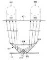
ここで、図4を参照し、図1の動作について説明する。光源12に電力が供給されると、光源12から光が放射され、スプリッタ16のV溝161の傾斜面から入射された光は、外側に分光されるとともに、スプリッタ16の傾斜面の角度と材料による屈折作用に基づき光源12の光軸方向と異なる複数の方向に配光される。配光された光は、スプリッタ16の出射側163から出射される。スプリッタ16に入射したほとんどの光が配光され外側に放射される。 Here, the operation of FIG. 1 will be described with reference to FIG. When electric power is supplied to the
出射側163から光源の光軸方向と異なる複数の方向に配光された光は、光学制御部材であるフレネルレンズ17に入射しレンズ部171を介して平行光に変換され、出射光421,422として照射面43にスポット照射される。レンズ部171は、一例として中心に対して同心円状に漸次受光した光を平行に変換する形状となっている。このため、照射面43の異なる位置に、ほぼ円形状の一点鎖線で示す照射エリア441,442の形状で照射させることができる。 Light distributed in a plurality of directions different from the optical axis direction of the light source from the
このように、光源12から出射された光は、スプリッタ16で光源の光軸方向と異なる複数の方向に配光された後、フレネルレンズ17で平行光に変換させて所望の照射形状を実現している。スプリッタ16で配光された光と光の間の光は、対向するV溝161の作用によりこの部分で通過する光量が極めて少ないものとなる。従って、スプリッタ16は、光源12で発生させた光を効率的にレンズ部171に入射させることができ、光の効率的な利用に寄与する。 In this way, the light emitted from the
この実施形態では、光源から出射された光をスプリッタで、光源の光軸方向と異なる複数の方向に配光させたのち、平行光に変換して複数の照射エリアを得るようにしたことから、少なくとも単一光源から効率的に複数のスポット照明となる照射エリアを得ることができる。 In this embodiment, the light emitted from the light source is distributed by a splitter in a plurality of directions different from the optical axis direction of the light source, and then converted into parallel light to obtain a plurality of irradiation areas. An irradiation area that efficiently becomes a plurality of spot lights can be obtained from at least a single light source.
なお、フレネルレンズ17は、2か所の照射エリアを有するスポット照明を得るための例として、2か所設けたが、2か所をカバーする大きめの1個のフレネルレンズによる2か所のスポット照明としても構わない。また、複数のレンズは同一の基板状に形成されたものでなくてもよく、複数のフレネルレンズを用いても構わない。照射エリアは、フレネルレンズの曲率をレンズの中心から左右上下に変化させることにより、球面あるいは非球面の形状とすることができる。 Although two Fresnel
また、スプリッタは石英ガラス製としたが、透光性で光源の発する熱に耐え得るものであればよく、アクリル等の合成樹脂製であってもよい。スプリッタ16は、一般的にプリズムシートと呼称される光学シートであってもよい。要は光源12からの光を効率的に配光させる機能を有するものであれば差し支えない。さらに、V溝161は、スプリッタ16に入射した光の出射面側に設けてもよい。 The splitter is made of quartz glass, but may be made of a synthetic resin such as acrylic as long as it is translucent and can withstand the heat generated by the light source. The
図5は、フレネルレンズについてさらに説明するための説明図である。図5のレンズは171のみを示すとともに、スプリッタ16は省略してある。 FIG. 5 is an explanatory diagram for further explaining the Fresnel lens. The lens of FIG. 5 shows only 171 and the
図5(a)のフレネルレンズ17は、出射面のみにレンズ171の機能を形成したものである。この場合の照射面における照度は、レンズの中心のレベルが高く、その周辺のレベルが低い状態となる。 The
図5(b)のフレネルレンズ17は、出射面のレンズ171の他に入射面にもレンズ部173の機能を形成したものである。この場合の照射面における照度は、レンズ部173の作用により光源12の中心方向に出射された光は照射面の周辺側に、光源12の外方向に出射された光は外側に照射させている。このため、照射面43では中央とその周辺における均斉度の向上を図ることができる。 The
なお、フレネルレンズ17は図5(a)のもの使うか、図5(b)のものを使用するかは照射エリアの使用目的により選択すればよい。 Whether the
図6は、この発明の照明装置に関する第2の実施形態について説明するための説明図である。以下の実施形態において、上記実施形態と同一の構成や機能部分には同一の符号を付し、ここでは異なる部分を中心に説明する。 FIG. 6 is an explanatory diagram for explaining a second embodiment relating to the illumination device of the present invention. In the following embodiments, the same reference numerals are given to the same configurations and functional parts as those in the above embodiment, and different parts will be mainly described here.
この実施形態は、フレネルレンズに換わる配光手段である凸型のレンズ61を用いたものである。また、スプリッタ16は配光して入射された光が混ざらないようにするために、配光された光にそれぞれ対応するものを使用するか、スリット62を形成したものを使用する。 In this embodiment, a
この場合、光源12から出射された光は、レンズ61で光源12から広がる方向に放射された光を平行光になるように変換される。このとき、レンズ61の光軸方向には光量の少ない光41として放射され、光軸から広がる方向は光量の多い光としてレンズ61で平行光に変換されスプリッタ16に入射される。スプリッタ16のV溝161の傾斜部分から入射された光は、出射光421,422に配光され、照射面43に照射エリア441,442として出射される。 In this case, the light emitted from the
この実施形態の場合も、照射エリアの照度には寄与しないレンズ61の光軸方向の光量を小さくできることから、光源12で発生された光を効率的に利用することができ、照射エリア441,442の照度を向上させることができる。 Also in this embodiment, since the amount of light in the optical axis direction of the
なお、レンズ61は、光源12から出射された光を平行光にするとしたが、必ずしも平行光にする必要はなく、必要とする照射エリアの面積や照度により異なってくるものである。 In addition, although the
図7は、この発明の照明装置に関する第3の実施形態について説明するための説明図である。 FIG. 7 is an explanatory diagram for explaining a third embodiment relating to the illumination device of the present invention.
この実施形態は、レンズ71に、入射された光を配光させる配光手段の機能と照射面に所望の照射エリアで照射させる光学的な変換を行う光学制御手段の機能を備えた形状を持せたものである。 In this embodiment, the
図7に示すように、レンズ71は光源12の光を入射させる入射面711が円錐形状をし、照射面43に出射される出射面712が中央に凹み713を有する凸形状をしている。 As shown in FIG. 7, the
入射面711に光源12の光が入射されると、レンズ71は凸レンズの光学的な作用により、光軸を跨って入射された側から広がる方向に出射される。このとき、レンズ71の形状を平行光となるように設計することにより、照射面43には図7に示すような照射エリア441,442を得ることができる。レンズ71の凹み713は、レンズ71の光軸上周辺では高い光量で光が出射されないようにするためのものである。When the light from the
なお、レンズ71は、光源12から入射された光を必ずしも平行光にして出射させる必要はなく、必要とする照度とエリアの関係で光学上の設計が図られるものである。 The
この実施形態でも、照射エリアの照度には寄与しないレンズ71の光軸方向から出射される光量を小さくできることから、光源12で発生された光を効率的に利用することができ、照射エリア441,442の照度を向上させることができる。 Also in this embodiment, the amount of light emitted from the optical axis direction of the
図8は、この発明の照明装置に関する第4の実施形態について説明するための説明図である。 FIG. 8 is an explanatory diagram for explaining a fourth embodiment relating to the illumination device of the present invention.
この実施形態は、図7のレンズ71に相当するレンズ81を用いたものである。レンズ81は、光源12の光が入射される入射面811が、光源12が配置された方向に遠ざかる方向に最も凸となる三角錐の入射部812と光が出射される出射面813の中央部に底が平坦な形状の凹部814から形成される。このレンズ81も入射された光を配光させる配光手段の機能と照射面に所望の照射エリアで照射させる光学的な変換を行う光学制御手段の機能を備えている。 In this embodiment, a
レンズ81の入射部812に入射された光源12の光は、入射面811で配光された光の光軸方向で一部全反射し、照射エリア441あるいは442に導かれる。光源12の光は、照射エリア441,442に導かれる光以外には実質的にレンズ81からは出射されないことから効率的な光の利用が可能となる。 The light of the
この実施形態の場合も照射エリアの照度には寄与しないレンズ81から出射光量を小さくできることから、光源12で発生された光を効率的に利用することができ、照射エリア441,442の照度を向上させることができる。 Also in this embodiment, the amount of light emitted from the
図9、図10は、この発明の照明装置に関する第5の実施形態について説明するための、図9は説明図、図10は図9要部の拡大斜視図である。 FIGS. 9 and 10 are explanatory views, and FIG. 10 is an enlarged perspective view of the main part of FIG. 9, for explaining a fifth embodiment relating to the lighting device of the present invention.
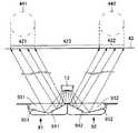
この実施形態は、図8のレンズ81と同機能を有するリフレクタ91に換えたものである。光源12の光が出射される側とリフレクタ91,92は、対向して配置される。リフレクタ91,92は、それぞれ光源12の光を配光させるとともに集光させる機能を備える。すなわち、リフレクタ91,92は入射された光を配光させる配光手段の機能と照射面に所望の照射エリアで照射させる光学的な変換を行う光学制御手段の機能を備えたものである。 In this embodiment, a
光源12とリフレクタ91,92は、空気層931,932を介して対向配置される。リフレクタ91,92は、光源12の中央付近から出射された光の領域を反射させる内側の第1の傾斜部941,942とこれらにそれぞれつながり光源12の外側の位置から出射された光の領域を反射させる第2の傾斜部951,952から形成される。第1の傾斜部941,942と第2の傾斜部951,952は角度を異ならせてある。第1の傾斜部941と第2の傾斜部951とには凹部961を、第2の傾斜部942と第2の傾斜部952とには凹部962が形成される。 The
光源12の光は、空気層931,932をそれぞれ介してリフレクタ91,92の第1の傾斜部941,942と第2の傾斜部951,952でそれぞれ配光される。第1の傾斜部941,942それに第2の傾斜部951,952では、入射された光を全反射させ、照射エリア441あるいは442に導かれる。光源12の光は、照射エリア421,422に導かれる光以外には出射されないことから効率的な光の利用が可能となる。このため、照射エリア441,442の中間の領域443への光の漏れを防止することができる。 The light from the
この実施形態では、光軸を同じとする少なくとも1個の半導体による光源から複数個所にスポット照射を実現することができる。さらに、光源12からの出力を所望のスポット部分に照射させることができることから、より効率的な照射を実現することが可能となる。 In this embodiment, spot irradiation can be realized at a plurality of locations from a light source of at least one semiconductor having the same optical axis. Furthermore, since the output from the
なお、第1および第2の傾斜部は、その傾きや形状を変えることで集光の制御を行い、必要とする照射エリアの面積や形状を変えることができる。 Note that the first and second inclined portions can control the light collection by changing the inclination and shape thereof, and can change the area and shape of the required irradiation area.
この発明のいくつかの実施形態を説明したが、これらの実施形態は、例として提示したものであり、発明の範囲を限定することは意図していない。これら新規な実施形態は、その他の様々な形態で実施されることが可能であり、発明の要旨を逸脱しない範囲で、種々の省略、置き換え、変更を行うことができる。これら実施形態やその変形は、発明の範囲や要旨に含まれるとともに、特許請求の範囲に記載された発明とその均等の範囲に含まれる。 Although several embodiments of the present invention have been described, these embodiments are presented as examples and are not intended to limit the scope of the invention. These novel embodiments can be implemented in various other forms, and various omissions, replacements, and changes can be made without departing from the scope of the invention. These embodiments and modifications thereof are included in the scope and gist of the invention, and are included in the invention described in the claims and the equivalents thereof.
11 ハウジング
12 光源
14 絶縁基板
16 スプリッタ
161 V溝
162 逆V
163 出射側
17 フレネルレンズ
171,173 レンズ部
18 アウターカバー
421,422 出射光
43 照射面
441,442 照射エリア
61,71,81 レンズ
711,811 入射面
712,813 出射面
713 凹み
812 入射部
91,92 リフレクタ
941,942 第1の傾斜面
951,952 第2の傾斜面11
163
Claims (2)
Translated fromJapanese前記光源の光軸と対向する位置に配置され、前記光源から光軸方向に放射された光を、異なる複数方向に配光させる傾斜面を入射面側もしくは出射面側に設けたシート状または板状のレンズ部材と、
前記レンズ部材と離間して配置され、前記レンズ部材を介して配光した光を、所望の方向に光学的に制御する光学制御部材と、を備えてなることを特徴とする照明装置。A semiconductor light source having a radiation distribution pattern having a maximum point on the optical axis;
A sheet or plate that is disposed at a position facing the optical axis of the light source, and has an inclined surface on the incident surface side or the emission surface side that distributes light emitted in the optical axis direction from the light source in different directions. A lens member,
An illuminating device comprising: an optical control memberthat is disposed apart from the lens member and optically controls light distributed through the lens member in a desired direction.
Priority Applications (1)
| Application Number | Priority Date | Filing Date | Title |
|---|---|---|---|
| JP2010153152AJP5560970B2 (en) | 2010-07-05 | 2010-07-05 | Lighting device |
Applications Claiming Priority (1)
| Application Number | Priority Date | Filing Date | Title |
|---|---|---|---|
| JP2010153152AJP5560970B2 (en) | 2010-07-05 | 2010-07-05 | Lighting device |
Publications (2)
| Publication Number | Publication Date |
|---|---|
| JP2012015065A JP2012015065A (en) | 2012-01-19 |
| JP5560970B2true JP5560970B2 (en) | 2014-07-30 |
Family
ID=45601236
Family Applications (1)
| Application Number | Title | Priority Date | Filing Date |
|---|---|---|---|
| JP2010153152AActiveJP5560970B2 (en) | 2010-07-05 | 2010-07-05 | Lighting device |
Country Status (1)
| Country | Link |
|---|---|
| JP (1) | JP5560970B2 (en) |
Families Citing this family (2)
| Publication number | Priority date | Publication date | Assignee | Title |
|---|---|---|---|---|
| ES2592173T3 (en) | 2009-09-25 | 2016-11-28 | Boston Scientific Scimed, Inc. | Tissue approach devices |
| JP6806358B2 (en)* | 2016-08-02 | 2021-01-06 | 嶋田プレシジョン株式会社 | In-vehicle lighting device |
Family Cites Families (5)
| Publication number | Priority date | Publication date | Assignee | Title |
|---|---|---|---|---|
| JP4789175B2 (en)* | 2005-02-25 | 2011-10-12 | 株式会社エンプラス | Surface light source device and display device |
| JP2009176471A (en)* | 2008-01-22 | 2009-08-06 | Stanley Electric Co Ltd | LED light source lens |
| JP5150335B2 (en)* | 2008-03-28 | 2013-02-20 | スタンレー電気株式会社 | Light guiding lens |
| JP5407054B2 (en)* | 2008-08-01 | 2014-02-05 | 日亜化学工業株式会社 | Lighting device |
| JP2010064684A (en)* | 2008-09-12 | 2010-03-25 | Lecip Corp | Lighting system |
- 2010
- 2010-07-05JPJP2010153152Apatent/JP5560970B2/enactiveActive
Also Published As
| Publication number | Publication date |
|---|---|
| JP2012015065A (en) | 2012-01-19 |
Similar Documents
| Publication | Publication Date | Title |
|---|---|---|
| US9188299B2 (en) | Lighting device | |
| KR20060107307A (en) | Virtual point light source | |
| CN101253364A (en) | LED headlight system | |
| CN107270151B (en) | Light-emitting device and laser illuminating lamp | |
| KR20090086173A (en) | License plate lamp | |
| JP5397186B2 (en) | Vehicle lighting | |
| KR20170095668A (en) | Lamp and Vehicle having the same | |
| JP6446202B2 (en) | Wide-angle diffusion optical system and illumination device using the same | |
| JP2015103323A (en) | Lighting device | |
| JP2008513967A (en) | Scattered LED array headlights | |
| JP2016224366A (en) | Luminous flux control member, light emitting device, and lighting device | |
| JP6624550B2 (en) | lighting equipment | |
| US10139067B2 (en) | Laser car lamp | |
| JP6501173B2 (en) | Lighting device | |
| JP5560970B2 (en) | Lighting device | |
| KR100991890B1 (en) | LED lighting module | |
| KR101568267B1 (en) | Line structure type led spot module included spot light type lens optical system for luminous intensity distribution control of multi-source | |
| KR101167045B1 (en) | Aspherical lens and aspherical lens having thereof | |
| JP5853128B2 (en) | lighting equipment | |
| JP2017168335A (en) | Lighting fixture for vehicle | |
| KR101055438B1 (en) | Lighting assembly and equalizer containing it | |
| JP2014203604A (en) | Lighting device | |
| JP4995342B1 (en) | Exposure light source and exposure apparatus using the same | |
| JP2009117375A (en) | Indoor illuminating device | |
| JP2007222790A (en) | Light convergence irradiation device and ultraviolet irradiation device |
Legal Events
| Date | Code | Title | Description |
|---|---|---|---|
| A711 | Notification of change in applicant | Free format text:JAPANESE INTERMEDIATE CODE: A712 Effective date:20130415 | |
| RD02 | Notification of acceptance of power of attorney | Free format text:JAPANESE INTERMEDIATE CODE: A7422 Effective date:20130416 | |
| A621 | Written request for application examination | Free format text:JAPANESE INTERMEDIATE CODE: A621 Effective date:20130417 | |
| A521 | Request for written amendment filed | Free format text:JAPANESE INTERMEDIATE CODE: A821 Effective date:20130417 | |
| A131 | Notification of reasons for refusal | Free format text:JAPANESE INTERMEDIATE CODE: A131 Effective date:20131224 | |
| A977 | Report on retrieval | Free format text:JAPANESE INTERMEDIATE CODE: A971007 Effective date:20131227 | |
| A521 | Request for written amendment filed | Free format text:JAPANESE INTERMEDIATE CODE: A523 Effective date:20140221 | |
| TRDD | Decision of grant or rejection written | ||
| A01 | Written decision to grant a patent or to grant a registration (utility model) | Free format text:JAPANESE INTERMEDIATE CODE: A01 Effective date:20140513 | |
| A61 | First payment of annual fees (during grant procedure) | Free format text:JAPANESE INTERMEDIATE CODE: A61 Effective date:20140526 | |
| R151 | Written notification of patent or utility model registration | Ref document number:5560970 Country of ref document:JP Free format text:JAPANESE INTERMEDIATE CODE: R151 |