JP5559863B2 - Ultra-compact form factor single-core optical fiber interconnect system having push-push insertion / extraction mechanism, shutter modular connector and shutter adapter, and method of use thereof - Google Patents
Ultra-compact form factor single-core optical fiber interconnect system having push-push insertion / extraction mechanism, shutter modular connector and shutter adapter, and method of use thereofDownload PDFInfo
- Publication number
- JP5559863B2 JP5559863B2JP2012282892AJP2012282892AJP5559863B2JP 5559863 B2JP5559863 B2JP 5559863B2JP 2012282892 AJP2012282892 AJP 2012282892AJP 2012282892 AJP2012282892 AJP 2012282892AJP 5559863 B2JP5559863 B2JP 5559863B2
- Authority
- JP
- Japan
- Prior art keywords
- connector
- ferrule
- adapter
- modular
- push
- Prior art date
- Legal status (The legal status is an assumption and is not a legal conclusion. Google has not performed a legal analysis and makes no representation as to the accuracy of the status listed.)
- Active
Links
- 230000007246mechanismEffects0.000titleclaimsdescription28
- 239000013307optical fiberSubstances0.000titledescription15
- 238000003780insertionMethods0.000titledescription13
- 230000037431insertionEffects0.000titledescription13
- 238000000034methodMethods0.000titledescription12
- 238000000605extractionMethods0.000titledescription3
- 239000000835fiberSubstances0.000description49
- 230000009977dual effectEffects0.000description20
- 230000003287optical effectEffects0.000description17
- 230000006835compressionEffects0.000description13
- 238000007906compressionMethods0.000description13
- 239000004606Fillers/ExtendersSubstances0.000description11
- 210000002445nippleAnatomy0.000description11
- 239000002184metalSubstances0.000description10
- 229910052751metalInorganic materials0.000description10
- 239000000543intermediateSubstances0.000description9
- 239000000463materialSubstances0.000description8
- 238000010586diagramMethods0.000description6
- 125000006850spacer groupChemical group0.000description6
- 230000013011matingEffects0.000description5
- 230000008569processEffects0.000description5
- 239000004033plasticSubstances0.000description4
- 229920003023plasticPolymers0.000description4
- 230000009471actionEffects0.000description3
- 238000006073displacement reactionMethods0.000description3
- 239000000428dustSubstances0.000description3
- 238000005498polishingMethods0.000description3
- 239000004593EpoxySubstances0.000description2
- 239000000853adhesiveSubstances0.000description2
- 230000001070adhesive effectEffects0.000description2
- 239000000919ceramicSubstances0.000description2
- 230000000994depressogenic effectEffects0.000description2
- 239000011521glassSubstances0.000description2
- 230000003993interactionEffects0.000description2
- 238000012986modificationMethods0.000description2
- 230000004048modificationEffects0.000description2
- 230000002265preventionEffects0.000description2
- 229920000271Kevlar®Polymers0.000description1
- 230000004308accommodationEffects0.000description1
- 230000009172burstingEffects0.000description1
- 238000010276constructionMethods0.000description1
- 239000000356contaminantSubstances0.000description1
- 238000011109contaminationMethods0.000description1
- 230000007547defectEffects0.000description1
- 238000013461designMethods0.000description1
- 210000005069earsAnatomy0.000description1
- 239000013013elastic materialSubstances0.000description1
- 231100000040eye damageToxicity0.000description1
- 230000001771impaired effectEffects0.000description1
- 150000002739metalsChemical class0.000description1
- 230000007935neutral effectEffects0.000description1
- 238000012546transferMethods0.000description1
Images


Classifications
- G—PHYSICS
- G02—OPTICS
- G02B—OPTICAL ELEMENTS, SYSTEMS OR APPARATUS
- G02B6/00—Light guides; Structural details of arrangements comprising light guides and other optical elements, e.g. couplings
- G02B6/24—Coupling light guides
- G02B6/36—Mechanical coupling means
- G02B6/38—Mechanical coupling means having fibre to fibre mating means
- G02B6/3807—Dismountable connectors, i.e. comprising plugs
- G02B6/389—Dismountable connectors, i.e. comprising plugs characterised by the method of fastening connecting plugs and sockets, e.g. screw- or nut-lock, snap-in, bayonet type
- G02B6/3893—Push-pull type, e.g. snap-in, push-on
- G—PHYSICS
- G02—OPTICS
- G02B—OPTICAL ELEMENTS, SYSTEMS OR APPARATUS
- G02B6/00—Light guides; Structural details of arrangements comprising light guides and other optical elements, e.g. couplings
- G02B6/24—Coupling light guides
- G02B6/36—Mechanical coupling means
- G02B6/38—Mechanical coupling means having fibre to fibre mating means
- G02B6/3807—Dismountable connectors, i.e. comprising plugs
- G02B6/3833—Details of mounting fibres in ferrules; Assembly methods; Manufacture
- G02B6/3847—Details of mounting fibres in ferrules; Assembly methods; Manufacture with means preventing fibre end damage, e.g. recessed fibre surfaces
- G02B6/3849—Details of mounting fibres in ferrules; Assembly methods; Manufacture with means preventing fibre end damage, e.g. recessed fibre surfaces using mechanical protective elements, e.g. caps, hoods, sealing membranes
- G—PHYSICS
- G02—OPTICS
- G02B—OPTICAL ELEMENTS, SYSTEMS OR APPARATUS
- G02B6/00—Light guides; Structural details of arrangements comprising light guides and other optical elements, e.g. couplings
- G02B6/24—Coupling light guides
- G02B6/36—Mechanical coupling means
- G02B6/38—Mechanical coupling means having fibre to fibre mating means
- G02B6/3807—Dismountable connectors, i.e. comprising plugs
- G02B6/3898—Tools, e.g. handheld; Tuning wrenches; Jigs used with connectors, e.g. for extracting, removing or inserting in a panel, for engaging or coupling connectors, for assembling or disassembling components within the connector, for applying clips to hold two connectors together or for crimping
- G—PHYSICS
- G02—OPTICS
- G02B—OPTICAL ELEMENTS, SYSTEMS OR APPARATUS
- G02B6/00—Light guides; Structural details of arrangements comprising light guides and other optical elements, e.g. couplings
- G02B6/24—Coupling light guides
- G02B6/36—Mechanical coupling means
- G02B6/38—Mechanical coupling means having fibre to fibre mating means
- G02B6/3807—Dismountable connectors, i.e. comprising plugs
- G02B6/381—Dismountable connectors, i.e. comprising plugs of the ferrule type, e.g. fibre ends embedded in ferrules, connecting a pair of fibres
- G02B6/3825—Dismountable connectors, i.e. comprising plugs of the ferrule type, e.g. fibre ends embedded in ferrules, connecting a pair of fibres with an intermediate part, e.g. adapter, receptacle, linking two plugs
- G—PHYSICS
- G02—OPTICS
- G02B—OPTICAL ELEMENTS, SYSTEMS OR APPARATUS
- G02B6/00—Light guides; Structural details of arrangements comprising light guides and other optical elements, e.g. couplings
- G02B6/24—Coupling light guides
- G02B6/36—Mechanical coupling means
- G02B6/38—Mechanical coupling means having fibre to fibre mating means
- G02B6/3807—Dismountable connectors, i.e. comprising plugs
- G02B6/381—Dismountable connectors, i.e. comprising plugs of the ferrule type, e.g. fibre ends embedded in ferrules, connecting a pair of fibres
- G02B6/3826—Dismountable connectors, i.e. comprising plugs of the ferrule type, e.g. fibre ends embedded in ferrules, connecting a pair of fibres characterised by form or shape
- G02B6/3829—Bent or angled connectors
Landscapes
- Physics & Mathematics (AREA)
- General Physics & Mathematics (AREA)
- Optics & Photonics (AREA)
- Mechanical Coupling Of Light Guides (AREA)
Description
Translated fromJapanese 本出願は、2005年1月12日付で出願された「シャッターコネクタとシャッターアダプタを有する超小型フォームファクターの単芯光ファイバ相互接続システム(Ultra-Small, Form Factor Single Fiber Optical Interconnect System With Shuttered Connector and Shuttered Adapter)」と題する同時係属出願11/036,306号の一部継続出願である、2005年6月17日付で出願された米国正式特許出願第11/155,360号に基づく優先権を主張する。 This application was filed on January 12, 2005, entitled “Ultra-Small, Form Factor Single Fiber Optical Interconnect System With Shuttered Connector and Claims priority based on US Patent Application No. 11 / 155,360, filed June 17, 2005, which is a continuation-in-part of
本発明は、光ファイバ相互接続システムに関し、詳しくは、ファイバコネクタプラグと光ファイバケーブルの正確な端部間(end-to-end)の合わせ(mating)のための対応するアダプタからなる超小型フォームファクター低損失の単芯光ファイバ相互接続システムに関する。さらに詳しくは、本発明は、モジュラー光ファイバコネクタおよび「プッシュ−プッシュ」挿入/引抜き機構を有する対応するアダプタからなる相互接続システム、およびその使用方法に関する。 The present invention relates to fiber optic interconnect systems, and in particular, microforms comprising corresponding adapters for precise end-to-end mating of fiber connector plugs and fiber optic cables. The present invention relates to a low loss single core optical fiber interconnection system. More particularly, the present invention relates to an interconnect system comprising a modular fiber optic connector and a corresponding adapter having a “push-push” insertion / extraction mechanism, and a method of use thereof.
光ファイバ分野において、単一チャネルまたは多重チャネルのコネクタとアダプタ双方においてコネクタとアダプタを接続しまたは接続解除する必要がたびたびある。ここに開示された本発明は、基本的に、単芯ファイバ用途に適用する。光ファイバ用途において、特に小さいサイズ、ルーティング、あるいは他の考慮事項のため、多数のファイバコネクタまたは多数のファイバフェルールが便利に到逹することができない場合において、高密度な相互接続システムに対する要求が増加し続けている。 In the fiber optic field, it is often necessary to connect or disconnect connectors and adapters in both single-channel or multi-channel connectors and adapters. The present invention disclosed herein basically applies to single-core fiber applications. Increased demand for high-density interconnect systems in fiber optic applications, especially when large fiber connectors or multiple fiber ferrules cannot be conveniently reached due to small size, routing, or other considerations I keep doing it.
一般的に、現在の単芯光ファイバコネクタプラグは、1.25〜2.5ミリメートルの直径範囲のフェルールにより製造されている。本発明によるサブミリメートル直径のフェルールの導入により、高密度な配置構成を許容する小型の単芯光ファイバコネクタおよびアダプタが可能である。光ファイバ分野においては、一つのファイバから他のファイバに永久的に、または臨時的に光を転送する必要がたびたびある。光コネクタプラグは、このような目的のために用いられる解決策の1つである。光コネクタプラグにより終端処理されるファイバは、ともに結合されることができ、必要に応じて、接続を終了し、または光を別のファイバにルーティングするために接続解除されてもよい。光コネクタプラグは、単芯ファイバまたは多心ファイバであってもよい。単芯ファイバコネクタプラグ(シンプレックスコネクタプラグ)は、他の単芯ファイバに対し、ただ一つのファイバの接続のみを提供する。多心ファイバコネクタプラグでは、いくつかのファイバが他の類似したファイバセットと同時に結合される。ここに開示された本発明は、基本的に単芯ファイバプリケーションに適用される。 In general, current single core fiber optic connector plugs are manufactured with ferrules in the diameter range of 1.25 to 2.5 millimeters. The introduction of a submillimeter diameter ferrule according to the present invention allows for a small single core optical fiber connector and adapter that allows for a high density arrangement. In the optical fiber field, there is often a need to transfer light either permanently or temporarily from one fiber to another. Optical connector plugs are one of the solutions used for such purposes. Fibers terminated by optical connector plugs can be coupled together and disconnected as necessary to terminate the connection or route the light to another fiber. The optical connector plug may be a single-core fiber or a multi-core fiber. Single fiber connector plugs (simplex connector plugs) provide only a single fiber connection to other single core fibers. In multi-fiber connector plugs, several fibers are combined simultaneously with other similar fiber sets. The invention disclosed herein is basically applied to single-core fiber applications.
通常的に、シンプレックスコネクタプラグでは、円筒状のフェルールを用いて接続が行われる。セラミックス、金属、プラスチックおよびガラスを含む多様な材料から製造され得るフェルールは、その中心に光ファイバよりわずかに大きい直径の同軸チャネルを有する。光ファイバが前記チャネル内に挿入され、エポキシのような接着剤、または機械的なクランピングにより維持固定される。ファイバの一端部は、フェルールの端部面からわずかに突出し、または平坦に作られ、その後、非常に滑らかな面を提供する研磨手順、または他の手段によって一般的に仕上げされる。 Usually, in a simplex connector plug, a connection is made using a cylindrical ferrule. Ferrules that can be manufactured from a variety of materials including ceramics, metals, plastics and glass have a coaxial channel with a diameter slightly larger than the optical fiber in the center. An optical fiber is inserted into the channel and maintained and secured by an adhesive such as epoxy, or mechanical clamping. One end of the fiber protrudes slightly from the end face of the ferrule or is made flat and then is typically finished by a polishing procedure or other means that provides a very smooth surface.
2つのコネクタ(以下、「コネクタプラグ」という場合がある)は、アダプタを利用して突き合わせられる。前記コネクタプラグは、フェルールとフェルールホルダとを備える。アダプタは、両方のコネクタプラグのフェルールを整列させる内部円筒状のスリーブを、ほとんどの場合に有する。現在の光ファイバコネクタは、両ファイバ端部を物理的に接触するために、フェルールを互いに対向して力を制御して押し入れ、それにより、接続の光学性能を向上するばね機構を通常有する。 Two connectors (hereinafter sometimes referred to as “connector plugs”) are abutted using an adapter. The connector plug includes a ferrule and a ferrule holder. The adapter has in most cases an internal cylindrical sleeve that aligns the ferrules of both connector plugs. Current fiber optic connectors usually have a spring mechanism to force the ferrules against each other in a controlled manner to push the ferrules into physical contact, thereby improving the optical performance of the connection.
ファイバ端部の仕上げまたは研磨は、フェルールの端面表面の少し下、または少し上にファイバを位置させる非常に関連している細心の注意を要する手順である。フェルールの端部からのファイバの突出は、物理的な接触のとき、ファイバ端部の損傷を回避するために、非常に厳格な許容誤差以内に制御されなければならない。ファイバ間の圧力は、その弾性領域にガラスを保持するために、狭い範囲で維持され、それにより、2つのコネクタプラグが合わされるとき、ファイバの破裂を防止するだけでなく、フェルールチャネルの内部におけるファイバの移動(ピストニング)を防止することができる。特に、光が進行するファイバの中心コアの断面に、スクラッチおよび他の欠陷のない非常に滑らかな表面を得ることが非常に重要である。特に、フェルールの端部とファイバとは、一般的に一緒に研磨されるので、このような手順の間、剥離されるフェルール材料が、ファイバの端部を損傷することを防止する必要がある。フェルールの直径を極めて小さくすることにより、研磨手順の間にファイバをより容易に、かつ迅速に研磨することができる。 Finishing or polishing the fiber end is a very relevant and meticulous procedure that positions the fiber slightly below or slightly above the end surface of the ferrule. The protrusion of the fiber from the end of the ferrule must be controlled within very tight tolerances to avoid damage to the fiber end when in physical contact. The pressure between the fibers is maintained in a narrow range to hold the glass in its elastic region, thereby not only preventing the fiber from bursting when the two connector plugs are mated, but also inside the ferrule channel. Fiber movement (pistoning) can be prevented. In particular, it is very important to obtain a very smooth surface free of scratches and other defects in the cross section of the central core of the fiber through which light travels. In particular, since the ferrule end and the fiber are typically polished together, it is necessary to prevent the peeled ferrule material from damaging the fiber end during such a procedure. By making the ferrule diameter very small, the fiber can be polished more easily and quickly during the polishing procedure.
汚れまたはほこりのような汚染物から光ファイバコネクタプラグを保護することもまた非常に重要である。ファイバの端部上の汚れまたはほこりは、光を散乱し、または吸収して、信号の過度な損失をもたらし、したがってシステム性能を不良なものとする。コネクタプラグの内部に汚染物があれば、誤整列により、類似した結果をもたらすことがある。同様に、転送される光の強度のため、目の損傷を防止するために、意図されない視角からユーザを隠すことが重要である。 It is also very important to protect the fiber optic connector plug from contaminants such as dirt or dust. Dirt or dust on the end of the fiber scatters or absorbs light, resulting in excessive signal loss and thus poor system performance. Any contamination inside the connector plug can result in similar results due to misalignment. Similarly, because of the intensity of the transmitted light, it is important to hide the user from unintended viewing angles to prevent eye damage.
光ファイバ用途において、特に多数のファイバコネクタプラグまたは多数のファイバフェルールが、ルーティングまたは他の考慮事項のために便利でない場合において、高密度な相互接続システムに対する要求も増加し続けている。一般的に、現在の単芯光ファイバコネクタプラグは、1.25〜2.5ミリメートルのフェルールの直径で製造されている。本発明によりサブミリメートル直径のフェルールを導入することにより、非常に高密度な配置構成を許容する非常に小さい単芯光ファイバコネクタプラグが可能である。 In fiber optic applications, the demand for high density interconnect systems continues to increase, especially when multiple fiber connector plugs or multiple fiber ferrules are not convenient for routing or other considerations. In general, current single-core fiber optic connector plugs are manufactured with ferrule diameters of 1.25 to 2.5 millimeters. By introducing a submillimeter diameter ferrule according to the present invention, very small single-core fiber optic connector plugs that allow very high density arrangements are possible.
本発明の一つの目的は、高密度用途に適した非常に小さいフットプリント、単芯光ファイバ相互接続システムを提供することであり、前記相互接続システムは、従来の光ファイバ相互接続システムが到逹して活性化しにくい環境において、迅速、かつ便利な接続動作/接続解除動作のためのプッシュ−プッシュ機構を有する。ここに開示されたシステムの一実施形態は、2つの小型コネクタおよびアダプタを備える。前記小型コネクタは、ベア光ファイバおよびケーブル光ファイバの受け取りを可能とするために、サブミリメートル直径のフェルールを取り扱うことができる。前記プッシュ−プッシュ機構は、コネクタの内部のばねだけでなく、アダプタ内の2つの同じばねにより制御され、小型コネクタがアダプタの内部に接続され、またはアダプタの内部との接続を絶たれるとき、自動的に作動する。本発明の本バージョンにおいては、第一にコネクタに対し押し入れて、コネクタをアダプタに接続する。第二にコネクタに対し押し入れて、コネクタをアダプタから短絡させる。 One object of the present invention is to provide a very small footprint, single-core optical fiber interconnect system suitable for high density applications, which can be a conventional optical fiber interconnect system. In an environment that is difficult to activate, it has a push-push mechanism for quick and convenient connection / disconnection operations. One embodiment of the system disclosed herein comprises two miniature connectors and an adapter. The miniature connector can handle submillimeter diameter ferrules to allow receipt of bare and cable optical fibers. The push-push mechanism is controlled not only by the spring inside the connector, but also by two identical springs in the adapter, and automatically when the small connector is connected to or disconnected from the adapter. It works automatically. In this version of the invention, the connector is first pushed into the connector to connect the connector to the adapter. Secondly, the connector is pushed into the connector to short-circuit the connector from the adapter.
本発明の他の目的は、高密度用途に適した非常に小さいフットプリント、単芯光ファイバ相互接続システムを提供することである。ここに開示されたシステムの他の実施形態は、2つのモジュラーコネクタおよびアダプタを備える。モジュラーコネクタは、ベア光ファイバおよびケーブル光ファイバを受け取る一実施形態において、サブミリメートル直径のフェルールを取り扱うことができる。本発明の本バージョンにおいては、ほこりとレーザ保護シャッターが、モジュラーコネクタとアダプタの両方に含まれる。これらのシャッターは、ばね機構により制御され、モジュラーコネクタとアダプタが取り付けられ、または取り除かれるとき、自動的に開閉される。接続を堅固に維持するラッチがさらに含まれ、モジュラーコネクタとアダプタを能動的に解体する解除機構がコネクタの本体に含まれている。これは、非常に小さいコネクタプラグの取り扱いを容易とする。EMI(電磁気干渉)防止がモジュラーコネクタおよびアダプタの両方に含まれている。 Another object of the present invention is to provide a very small footprint, single fiber optic interconnect system suitable for high density applications. Other embodiments of the system disclosed herein comprise two modular connectors and an adapter. Modular connectors can handle submillimeter diameter ferrules in one embodiment that accepts bare optical fiber and cable optical fiber. In this version of the invention, dust and laser protection shutters are included in both the modular connector and the adapter. These shutters are controlled by a spring mechanism and automatically open and close when the modular connector and adapter are attached or removed. A latch is further included to maintain a secure connection, and a release mechanism for actively disassembling the modular connector and adapter is included in the connector body. This facilitates handling of very small connector plugs. EMI prevention is included in both modular connectors and adapters.
アダプタは、フェルール整列を可能とする、十分な自由を提供するフローティングスリーブを含む。理想的には、もしあれば、各コネクタの光軸を中心とする最小のフェルール回転により、スリーブ内におけるフェルールのフローティング接続を提供するのが目的である。同様に、変位が、2つの合わされたフェルール間の最適な接続達成をより困難にするため、フェルールの傾斜(すなわち、光軸に対するフェルールの上方へまたは下方への変位)は、最小化される。これは、光軸に対して8°に研磨された端部を有することができる角度研磨されたフェルールを用いるコネクタに特に重要である。前記フェルールの角のある端部は、2つのコネクタの対面方式の合わせ面である。フェルールの回転が許容されると、またはフェルールの過度な傾斜が許容されると、結合されるコネクタ間の最適な接続は達成されない。光軸を中心とするフェルール回転の防止も、フェルールの最適な同調性(tunability)のために重要である。 The adapter includes a floating sleeve that provides sufficient freedom to allow ferrule alignment. Ideally, the objective is to provide a floating connection of the ferrule within the sleeve, if any, with minimal ferrule rotation about the optical axis of each connector. Similarly, the tilt of the ferrule (ie, the upward or downward displacement of the ferrule relative to the optical axis) is minimized because the displacement makes it more difficult to achieve an optimal connection between the two mated ferrules. This is particularly important for connectors that use angle-polished ferrules that can have ends polished at 8 ° to the optical axis. The cornered end of the ferrule is a face-to-face mating surface of two connectors. If the rotation of the ferrule is allowed or excessive tilting of the ferrule is allowed, the optimum connection between the connectors to be joined is not achieved. Prevention of ferrule rotation about the optical axis is also important for optimal tunability of the ferrule.
本発明のシャッターコネクタとシャッターアダプタのバージョンにおいて、モジュラーコネクタシャッター機構は、モジュラーコネクタがアダプタの内部に挿入されるとき、横軸を中心に上方に回転することにより自動的に開かれ、その後、フェルールを動作可能に露出するために退避するばね負荷回転ドアを提供する。シャッタードアは、コネクタハウジングの後方に向けて開位置に摺動する。コネクタがアダプタから取り外されるとき、シャッター圧縮ばねが膨張されてシャッターが閉位置に到逹するまで、シャッターをコネクタの前方に向けて移動させる。説明の便宜上、横に搭載されたコネクタシャッタードアの例を用いているが、他の種類のシャッタードアまたは回転軸は、本発明の範囲内にあるものとみなすべきである。 In the version of the shutter connector and shutter adapter of the present invention, the modular connector shutter mechanism is automatically opened by rotating upward about the horizontal axis when the modular connector is inserted into the adapter, and then the ferrule. A spring-loaded revolving door is provided that retracts to operably expose. The shutter door slides to the open position toward the rear of the connector housing. When the connector is removed from the adapter, the shutter is moved toward the front of the connector until the shutter compression spring is expanded and the shutter reaches the closed position. For convenience of explanation, the example of a horizontally mounted connector shutter door is used, but other types of shutter doors or rotating shafts should be considered within the scope of the present invention.
本発明のモジュラーコネクタバージョンにおけるアダプタシャッターの機構は、アダプタの各端部において、垂直軸を中心に回転するように搭載されたシャッタードアのカムに作用するS字状のばねを備える。ばねクリップス、コイルばね、トーションばね、弾性材料などのような、シャッタードアを正常に閉鎖された位置に付勢するための他の種類のばねおよび手段は、本発明の範囲内にあるものとみなすべきである。アダプタがモジュラーコネクタを開放端部に挿入していない場合、コネクタを閉位置に付勢するために、S字状ばねは、開放端部においてシャッタードアのカムに押し入れる。コネクタがアダプタの開放端部の内部に押し入れられた場合、コネクタシャッタードアが退避して、フェルールプラグが露出し、コネクタの前方がアダプタドアを押し入れてアダプタドアに対するS字状ばねの力を克服して開位置に自動的に移動する。モジュラーコンタクトとコネクタとを集めるラッチング機構がモジュラーコネクタ上に提供される。前記ラッチング機構は、モジュラーコネクタに含まれて、非常に小さいフットプリントシステムによるその使用を容易にする。コネクタとアダプタとを集める機構は、プッシュ−プッシュ機構である。上述されたラッチング機構は、通常のモジュラーコンタクトとコネクタとを集める。 The adapter shutter mechanism in the modular connector version of the present invention comprises an S-shaped spring acting on the shutter door cam mounted at each end of the adapter to rotate about a vertical axis. Other types of springs and means for biasing the shutter door to the normally closed position, such as spring clips, coil springs, torsion springs, elastic materials, etc., are considered within the scope of the present invention. Should. When the adapter does not insert the modular connector into the open end, the S-shaped spring pushes into the shutter door cam at the open end to urge the connector to the closed position. When the connector is pushed into the open end of the adapter, the connector shutter door is retracted, the ferrule plug is exposed, and the front of the connector pushes the adapter door to overcome the force of the S-shaped spring against the adapter door. Automatically move to the open position. A latching mechanism for collecting modular contacts and connectors is provided on the modular connectors. The latching mechanism is included in the modular connector to facilitate its use by a very small footprint system. The mechanism that collects the connector and the adapter is a push-push mechanism. The latching mechanism described above collects conventional modular contacts and connectors.
モジュラーコンタクトとコネクタとのゼロ回転の実施形態においては、2方向または3方向へのフェルールの直線移動または曲線移動が可能であり、光軸に対するフェルールの望まれていない変位を最小化しながら、望まれていない回転を防止する。上方移動および下方移動の軸は、説明の便宜上、互いに直交する垂直および水平としてここに図示されている。しかし、上方向移動と下方向移動、および/または直交しない移動軸の他の角度も、本発明の範囲内にあるものとみなすべきである。 In the zero rotation embodiment of the modular contact and connector, linear or curvilinear movement of the ferrule in two or three directions is possible, while minimizing unwanted displacement of the ferrule relative to the optical axis. To prevent rotation. The axes of upward and downward movement are shown here as vertical and horizontal orthogonal to each other for convenience of explanation. However, upward and downward movement and / or other angles of non-orthogonal axes of movement should also be considered within the scope of the present invention.
シンプレックス(simplex)、デュプレックス(duplex)、フロントパネル、バックプレーン、またはミドルプレーンシステムのような単一チャネルおよび多重チャネルシステムのすべての可能な配置構成に実質的に用いられる面で、モジュラーコネクタの配置構成は一般的である。 Modular connector placement in terms of use in virtually all possible configurations of single-channel and multi-channel systems such as simplex, duplex, front panel, backplane, or middleplane systems The configuration is common.
モジュラーコンタクトアセンブリは、長手方向軸を有するフェルールプラグを備える。前記プラグはまた、セラミックスフェルールを含む。シェルがフェルールプラグを保持し、1つ以上のリミッタを有する。前記プラグと前記シェルとは、フェルールが他のフェルールと接触されているとき、長手方向軸に沿って軸方向に移動することができるようにするために、互いに動作可能に接続されている。 The modular contact assembly includes a ferrule plug having a longitudinal axis. The plug also includes a ceramic ferrule. A shell holds the ferrule plug and has one or more limiters. The plug and the shell are operatively connected to each other so that they can move axially along the longitudinal axis when the ferrule is in contact with another ferrule.
フェルールのばね負荷は、シェル内でフェルールを前方に付勢するように機能するコイルばねにより提供される。フェルールホルダは、シェルのリミッタと係合するためのその周辺部まわりに少なくとも一つの平坦な領域を有するフランジを備えて、長手方向軸を中心とするフェルールの回転を防止する。カラーもまた、フェルールホルダ上に提供されて、長手方向軸を中心とするフェルールの回転を防止する。 The ferrule spring load is provided by a coil spring that functions to bias the ferrule forward within the shell. The ferrule holder includes a flange having at least one flat region around its periphery for engaging the shell limiter to prevent rotation of the ferrule about the longitudinal axis. A collar is also provided on the ferrule holder to prevent rotation of the ferrule about the longitudinal axis.
本発明の他の実施形態は、アダプタ本体を含み、前記アダプタ本体は、その端部に前記本体の内部に導く少なくとも2つの開口部を有し、前記本体の内部には、バレルと該バレル内の整列スリーブが、フローティング配列で含まれている。コネクタが前記端部開口部を介して挿入されて、他のコネクタのフェルールとの端部間の整列接触で維持されることができる。プッシュ−プッシュ機構は、コネクタとアダプタとを集める。 Another embodiment of the invention includes an adapter body, the adapter body having at least two openings leading to the interior of the body at an end thereof, wherein the interior of the body includes a barrel and an interior of the barrel. Alignment sleeves are included in a floating arrangement. A connector can be inserted through the end opening and maintained in aligned contact between the ends of the other connector ferrules. The push-push mechanism collects connectors and adapters.
本発明の多くの他の特徴および利点は、次の詳細な説明、添付された図面および添付された特許請求範囲から明確になる。 Many other features and advantages of the present invention will become apparent from the following detailed description, the accompanying drawings, and the appended claims.
システムの設計は、ここに記載した次の図面に対する説明によりさらに理解されることができる。各図面に対する簡単な説明がここに含まれている。 The design of the system can be further understood with reference to the following drawings described herein. A brief description for each drawing is included here.
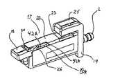
好ましい実施形態を開示することにより、これに限定されないが、図1は、本発明のモジュラーコンタクトアセンブリを図示する。前記モジュラーコンタクトアセンブリは、図3A〜図3Cのモジュラーコネクタの実施形態;図7Aのコネクタ/アダプタシステムの実施形態;図12〜図17fのプッシュ−プッシュコネクタ/アダプタシステムの実施形態;および図18〜図20の簡略化したコネクタ/アダプタシステム本体の実施形態250に用いられる。図1のアセンブリは、ばね負荷フェルール3とフェルールホルダ3Aとを備えるフェルールプラグに対してホルダとして機能する外部シェル2、ばね4および後方ニップルを有する。本実施形態において、シェル2は、金属製であるが、他の硬い材料の使用も本発明の範囲内にあるものとみなすべきである。 Although not limited to this by disclosing preferred embodiments, FIG. 1 illustrates the modular contact assembly of the present invention. The modular contact assembly includes the modular connector embodiment of FIGS. 3A-3C; the connector / adapter system embodiment of FIG. 7A; the push-push connector / adapter system embodiment of FIGS. 12-17f; and FIGS. Used in the simplified connector / adapter
ニップル5は、最適の性能のために、その回転または軸方向の移動なしに、図1に図示された位置に確固に維持されなければならない。ニップル5の望まれていない回転および軸方向の移動を防止するため、フラット6状のホルダがニップルのフランジ8に提供され、スロット7が外部シェル2に提供されている。作動時、フランジ8は、スロット7に導出して、それにより、シェル2に対するニップル5の軸方向の移動を防止する。フラット6は、外部シェル2の平坦なベッド9と接触し(図2参照)、それにより、ニップル5の回転をさらに防止する。 The
フェルール3はまた、アイドル位置にばね負荷されている間および動作位置にある間に回転されてはいけない。フェルール3のばね負荷を達成するため、図1に図示されたように、外部シェル2の前方端部に2つの耳10が提供される。本実施形態においては、コイルばねであるばね4は、ニップル5から耳10に向けてフェルールを付勢する傾向がある。シェル2に対するフェルール3の軸方向の移動を許容しながらフェルール3の回転を防止するために、4つのリミッタ11が外部シェル2に提供され、フェルールホルダ3Aは、4つのフラットを有するフランジ12を有する。シェルリミッタ11とフランジ12上のフラットの個数の他の動作的な組合は、本発明の範囲内にあるものとみなすべきである。このような配置構成によって、フェルールが他のフェルールと接触したとき、光軸(図9Aに図示される)に対するフェルール3の回転を許容せずに、長手方向軸に沿ったフェルールの軸方向の移動を許容することができる。 The ferrule 3 must also not be rotated while it is spring loaded in the idle position and in the operating position. In order to achieve the spring loading of the ferrule 3, two
フェルールの調整を可能とする目的で、上述した配置構成によれば、フェルール3が固定ニップル5に向けて(図1の観点)軸方向後方に押さえられることにより、フェルール3が外部シェル2の内部に退避されて、圧縮ばね4により提供される外部の付勢力を克服することができる。フェルール3が軸方向後方に充分押し入れられてリミッタ11 から解除されると、フェルール3は、回転することができ(この場合、4箇所の異なる位置全体に対して90゜増加)、ここでフランジ12の異なるフラットは、適当な調整道具(図10Aに図示される)を用いてリミッタ11と接触するようになる。 For the purpose of enabling adjustment of the ferrule, according to the arrangement described above, the ferrule 3 is pressed toward the fixed nipple 5 (in view of FIG. 1) in the axial rearward direction, so that the ferrule 3 is inside the
本実施形態においては、フェルール3が回転することができるようにすることにより(元の位置を超える)3ヶ所の異なる放射方向の位置への同調性が提供され、これらの放射方向の位置は、接続されるフェルールの間に、より良好な端部間の接続を潜在的に提供することができる。同じように、フランジ12上の3つのフラットだけがフェルールホルダ3Aに提供されると、フェルール3は、リミッタ11からフラット12の係合で退避されて、2ヶ所の他の放射方向位置に120度程度増加回転することができる。調整プロセスが完了した以後に、フェルール3が解除され、ばね4によって前方に押し入れられ、フィンガー10と接触するフランジ12の前方とともに作動位置に復帰される。 In this embodiment, allowing the ferrule 3 to rotate provides synchrony to three different radial positions (beyond the original position), and these radial positions are: A better end-to-end connection can potentially be provided between the connected ferrules. Similarly, when only three flats on the
図2は、底側を上面として図示したモジュラーコンタクト1の反転された断面図である。上述したことに付け加えて、プラグエクステンダ13も図示されており、前記エクステンダは、フェルール3の中心ボアの内部にエポキシ、または任意の他の適切な接着剤を注入してファイバを固定することを補助するのに通常用いられる。本発明では、以下により詳細に説明するように、プラグエクステンダは、フェルールホルダ3Aの中心ボア内において、図9Aの延長位置から光ファイバケーブル(図2には図示されず、図9Bに図示される)に対するコンタクト1を仕上げた以後のプラグエクステンダ13の最終位置である図2の位置まで摺動する。また、図2に図示されたように、ニップル5には、光ファイバケーブルに対するコンタクト1を仕上げると同時に、圧接信頼度の向上に使用される3つの環状歯14がある。また、図2には、モジュラーコンタクト1をモジュラーコネクタ17(図3Aおよび図3Bに図示される)に締め付けするように機能するラッチ15が図示されている。 FIG. 2 is an inverted cross-sectional view of the
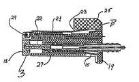
図3Aは、閉位置で、水平シャフト24上にばね搭載されたシャッター18が閉位置にあるモジュラーコネクタ17の斜視図である。モジュラーコネクタ17は、上述したモジュラーコンタクト1、本体19、トーションばね20および圧縮ばね21(図4Aおよび図4Bに図示される)を有するシャッター18、ラッチ23を有する外部シェル22、シャッター18のためのシャフト24(図4Aおよび図4Bに図示される)および解除ノブ25からなる。シャッター18は、通常、トーションばね20により閉位置に付勢される。 FIG. 3A is a perspective view of the
図3Bは、シャッターが中間開位置にあるモジュラーコネクタ17の斜視図である。モジュラーコネクタ17がアダプタ28(図5に図示される)の開口部29の1つの内部に導入されると、シャッター18は、その非対称プロング26(図3A参照)によりアダプタの入口29に当たり、図3Aの閉位置から図3Bに図示された中間水平位置に上方へ回転する。モジュラーコネクタ17がアダプタ28の内部にさらに押し入られると、シャッター18は、上方に突出し、スロット50A(図3B参照)に沿って摺動するプロング26により本体19の内部に後ろへ摺動し、それにより、プロング26がシェル22内のスロット50Aのエッジ51Aにより止められ(またはシャッター18が本体19の通路52Aに完全に退避され)、コネクタ17がそのラッチ23によりアダプタ28の内部にスナップされるまで、ばね21および圧縮ばね21のばね力を克服する。シャッター18は、本体19の内部の通路52Aに沿って押し入られるので、圧縮ばね21は、その上方向のばね力が克服され、ばね21が圧縮されるまで抵抗する。したがって、ばね21は、閉位置に向けて非退避位置にシャッター18を付勢する傾向がある。モジュラーコネクタ17がアダプタ28との係合から解除されるとき、シャッター18は、フェルール3を自動的に遮断する。 FIG. 3B is a perspective view of the
逆に、シャッター18の退避は、フェルールアセンブリ3に対する接近を開放し(図1参照)、したがってフェルールアセンブリ3は、反対側からアダプタ28の内部に導入されている同一の第2モジュラーコネクタ(図示せず)との物理的な端部間の作動可能な接触により係合され得る。このようなシャッター18の退避プロセスは、図4Bに図示されている。アダプタ28からモジュラーコネクタ17を解除するために、ノブ25が押下され、ラッチ23が速かにほぼ水平に置かれ、それにより、コネクタ17がアダプタ28との係合から解除され、2つのばね:(1)シャッター圧縮ばね21(図4A参照)および(2)圧縮ばね4(図1参照)により、アダプタ28からわずかに押退される。 Conversely, retracting the
圧縮ばね4は、4ヶ所の圧縮位置を有する:第一に、前記ばねは、外部シェル2に組み立てられるとき、少し圧縮され;第二に、前記ばねは、モジュラーコンタクト1がコネクタ本体19に組み立てられるとき(フェルール3は、本体19の固定された内部面27に対するその端部面16の接触によりばね負荷されている)より圧縮され;第三に、モジュラーコネクタ17がアダプタ28の内部の同一のコネクタ(図示せず)との物理的な接触により係合されているとき、前記圧縮ばね4は、作動レベルまでさらに圧縮され;最後に、フェルール3が調整手順の間、押し出されているとき、記圧縮ばね4は、硬い状態までほとんど圧縮されることができる。 The
図3Cは、モジュラーコネクタ17の分解図である。図3Cは、開口部19Aを介してコネクタ本体19の内部に挿入されるモジュラーコンタクト1を図示している。シャッタードア18は、シャフト24に回転可能に搭載されており、トーションばね20により下方に付勢されて閉位置になる。シャフト24は、シャッタードア18を外部に付勢するために、圧縮ばね21を保持するキャリッジ21Aにより保持されており、シャフト24が退避すると、ばね21は圧縮され、シャッタードア18は、水平位置まで上方に回転して本体19の後方端部(B)に向けて直線で移動する。シャッタードア18が水平位置にあると、プロング26は、それが端部51Aに到逹するまでスロット50Aに沿って摺動することができる。ノブ25は、シェル22のラッチ23を押下するように、位置合わせされている。 FIG. 3C is an exploded view of the
図4Aは、シャッター18が閉位置にあるモジュラーコネクタ17の断面図である。圧縮ばね21は、本体19の端部(B)から外部にシャッター18を付勢する。トーションばね20は、水平に搭載されたシャフト24を中心に、下にシャッター18を付勢する。 FIG. 4A is a cross-sectional view of the
図4Bは、シャッター18が中間開位置にあるモジュラーコネクタ17の断面図である。この位置では、コネクタ17は、アダプタ(図示せず)の内部に完全に挿入されない。また、図4Bは、モジュラーコンタクト1をモジュラーコネクタ17の本体19に完全に係合し、ばね負荷された状態で保持するラッチ15を図示する。ラッチ15の自由端部15A(図4B参照)は、モジュラーコンタクト1が本体19から解除されることを防止するためにフランジ15Bと接触する。しかし、図4Bに図示されたように、ラッチ15が上方に押し上げられると、フランジ15Bの上部に邪魔がなくなり、それによりモジュラーコンタクト1を本体19から退避することができる。また、図4Bは、結合されているとき(図示せず)、モジュラーコネクタ17をアダプタ28から解除するためにノブ25により下に押されるラッチ23を図示している。 FIG. 4B is a cross-sectional view of the
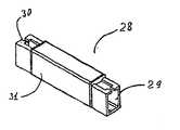
図5は、その端部に2つのアパーチャー29および30を有するアダプタ28を図示し、前記2つのアパーチャーには、2つのモジュラーコネクタ17(図3A参照)が挿入されるようになっている。図5はまた、EMI遮蔽だけでなく内部部品のホルダおよびカバーとして機能する外部シェル31を図示する。図6は、シャッター35および36、外部シェル31、およびばね32が除去されたアダプタ28の分解図である。図6はまた、2つのカム33および34を外部に付勢するS字状のばね32を図示し、前記2つのカムのそれぞれは、垂直に搭載されたシャッター35および36の端部に個別的に取り付けられている(図7参照)。本実施形態において、シャッター35および36のそれぞれは、垂直回転軸を有する。モジュラーコネクタ17がアダプタ28の収容アパーチャーの内部に挿入されていないと、ばね付勢されたカム33および34は、ばね32により押さえられ、したがってシャッター35および36は、閉位置に回転し、前記閉位置は、図9に図示された光軸または長手方向軸に対して実質的に垂直である。 FIG. 5 illustrates an
図7は、図5のアダプタ28の断面図である。図7はまた、閉位置にある2つのシャッター35および36を図示する。図7はまた、整列スリーブ38を内部に含むバレル37を図示する。整列スリーブ38は、ある程度、バレル37の内部において自由にフローティングできるため、アダプタ28の2つの対向側から端部間の物理的な接触で係合される2つのフェルール(図示せず)を最適に整列することができる。図20は、バレル253内の整列スリーブ254内において端部間の接触状態にある、このような2つのフェルールを図示する。 FIG. 7 is a cross-sectional view of the
図7Aは、モジュラーコネクタ17がアダプタ28の一端部の内部に完全に挿入されているモジュラーコネクタ/アダプタシステムの縦断面図である。フェルール3は、アダプタ28のバレル37内においてフローティングする整列スリーブ38内に収容されている。 FIG. 7A is a longitudinal cross-sectional view of a modular connector / adapter system with the
完全に挿入されると、シャッター18は完全に退避され、ばね21は、通路52A内において完全に圧縮される。どのようなモジュラーコネクタであっても、端部30に挿入されていないため、アダプタ28のシャッタードア35は、閉まったまま図示されている。アダプタ28の対向端部29にモジュラーコネクタ17を挿入すると、シャッタードア18が通路52Aおよびアダプタシャッタードア36(図示せず)の開口部の内部に自動的に退避される。ラッチ23がチャンバ23B内にキャプチャされて、チャンバ23Bの端部壁23Aと接触するために、モジュラーコネクタ17は、アダプタ28に対しラッチされており、それにより、アダプタ28からのコネクタ17の引抜きが防止される。アダプタ28からモジュラーコネクタ17を解除するために、ノブ25が充分に押下されて(図7Aで見たとき)、ラッチ23は、端部壁23Aの底面に邪魔がないようにすることができる。次に、コネクタ17が右側に(図7Aで見たとき)引き寄せられて、アダプタ28との係合から除去されることができる。 When fully inserted, the
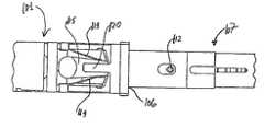
図8は、モジュラーコンタクトアセンブリ1の他の実施形態を図示する。本実施形態は、一般的なモジュラーコンタクトのAPC(angled physical contact)バージョンに適合している。APC環境においては、合わせフェルールが光軸に対し特定の角度で研磨されているため、光軸を中心とするフェルールの軸方向回転は、できるだけ回避される。 FIG. 8 illustrates another embodiment of the
同時に、光軸に垂直の平面(「X」および「Y」平面)におけるフェルールのフローティングが、通常に研磨されたフェルールに対して可能である。直線移動または曲線移動をもたらすXおよびY平面(図10に図示される)における移動を達成するため、図8に図示されたモジュラーコンタクトアセンブリ1は、図1に図示された同一のアセンブリと比べると、差を有する。このアセンブリは、2つのスロット39を有する類似した外部金属シェル2を有する。インサート40は、図10に図示されたように、コネクタ本体19の内部のアパーチャーにより制限されるY(垂直)方向に、これらのスロットにおいて自由に移動することができる(図3参照)。フェルール3の正方形のフランジ12は、図10に図示されたインサート40の矩形のアパーチャー41の内部においてX(水平)方向に自由に移動することができる。一般的なモジュラーコンタクト1の残りは、図1に対して図示され、説明されたコンタクトと比較可能である。 At the same time, ferrule floating in planes perpendicular to the optical axis ("X" and "Y" planes) is possible for normally polished ferrules. To achieve movement in the X and Y planes (illustrated in FIG. 10) resulting in linear or curvilinear movement, the
図8Aは、ゼロプラグ回転を有する一般的なモジュラーコンタクトの他の実施形態を図示する。インサート49は、対向側に2つのピン50を有する。これらのピンは、スロット39において上下に(図10においてY方向)移動することができる。同時に、インサート49は、ピン50の軸を中心にわずかに回転することができる。これがフェルール3に1つ以上の自由度を与えるが、光軸を中心に依然としてゼロプラグ回転を維持する(図9参照)。 FIG. 8A illustrates another embodiment of a typical modular contact with zero plug rotation. The
図9は、中間位置にあるフェルール3のインサート40およびフランジ12を図示し、したがってフェルールは、Y(垂直)方向に上、または下にわずかに移動することができる。 FIG. 9 illustrates the ferrule 3
図9Aは、フェルール3の金属ホルダ42の内部に部分的だけ挿入されたプラグエクステンダ13(また図2参照)を図示する。これは、一般的なモジュラーコンタクト1がケーブル48上において終了されるときに変更する中間位置である(図9B参照)。よって、エクステンダ13は、それがフェルール3の端部により生成されるストップ42Aに到逹するまでコンタクト1の内において摺動するので、ファイバ44とプラグエクステンダ13との間の割れやすい接合部がプラグ本体の外部に露出しない。 FIG. 9A illustrates the plug extender 13 (see also FIG. 2) partially inserted inside the
図9Bは、ケーブル48上において終了された一般的なモジュラーコンタクト1を図示する。図9Bは、またフェルールホルダ42の内部にストップ42Aまで完全に挿入されたプラグエクステンダ13を図示する。また、バッファー43がプラグエクステンダ13の端部13Aと接触するため、ファイバ44は、損傷しやすい、支持されていない位置に露出しない。さらに、図9Bは、ニップル5に対して相対的に移動することができないKevlar(登録商標)リニア46およびジャケット47を保持する圧接チュービング45を図示する。 FIG. 9B illustrates a typical
図10は、図9に図示された一般的なコンタクトの反転された断面A−Aを図示する。このセクションにおいて、インサート40は、外部シェル2の2つのスロット39の内部において中間位置に図示されている。インサート40は、距離±Yに対しY方向(この場合、垂直方向)に移動することができ、結果として、そのフランジ12により同一方向および距離でフェルール3を引くことができる。フェルール3のフランジ12はまた、距離±Xに対しX方向にインサート40の矩形のアパーチャーの内部において移動することができる。したがって、フェルール3は、XとY方向の両方に移動することができるが、光軸を中心に回転することは許容されない(図9参照)。 FIG. 10 illustrates an inverted cross-section AA of the general contact illustrated in FIG. In this section, the
図10Aは、取っ手70と、フェルールを掴み、押し、また調整するためのグリッピング端部72を有する金属インサート71を備える調整道具を図示する。本発明は、システムのサイズを減少する超小型サブミリメートルのフェルールの直径を用いることができる。 FIG. 10A illustrates an adjustment tool comprising a handle 70 and a metal insert 71 having a
図11は、アダプタ101の小型「プッシュ−プッシュ」バージョンを図示する。前記アダプタは、2つのプッシュ−プッシュ挿入−引抜き機構を備えるアダプタハウジング103のためのホルダとして機能する外部シェル102を有し(図14参照)、ラッチ104、2つのストッパ105、および2つのコネクタ107のための2つのアパーチャー106(一つのみ図示する)を有する(図14参照)。本実施形態において、外部シェル102は、金属製であるが、他の硬い材料の使用も本発明の範囲内にあるものとみなす。ハウジング103は、プラスチック製であるが、他の硬い材料(キャスト金属を含む)の使用も本発明の範囲内にあるものとみなす。 FIG. 11 illustrates a small “push-push” version of the
図12は、図11に図示された「プッシュ−プッシュ」アダプタとともに使用する小型コネクタ107を図示する。前記コネクタは、外部シェル108、前方シャッター109、光ファイバケーブル(図示せず)のためのブート110、コネクタハウジング111、およびアダプタ101のプッシュ−プッシュ機構(図11参照)との相互作用のためのデュアルピン112を有する。本実施形態において、外部シェル102は、金属製であるが、他の硬い材料の使用も本発明の範囲内にあるものとみなす。ハウジング111は、プラスチック製であるが、他の硬い材料(キャスト金属を含む)の使用も本発明の範囲内にあるものとみなす。ブート110は、実質的に硬いプラスチック製であるが、他の硬い材料(ハードテュロメーターゴムを含む)の使用も本発明の範囲内にあるものとみなす。ブート110は、タブ110aを有し、該タブは、ペン先のような適切なスタイラス様の部材、PDAスタイラス、ペータークリップの端部などによりプッシュ−プッシュ相互接続機構を作動させて、コネクタ107とアダプタ101を係合するために押さえられる。デュアルピン112は、断面がほぼ円形の上位部(図14参照)および断面がほぼ正方形の下位部(図17参照)を有する。 FIG. 12 illustrates a
図13は、小型のプッシュ−プッシュアダプタ101(図11参照)の部分分解図を図示する。この図においては、2つのプッシュ−プッシュ機構113がそれぞれのアパーチャー106の近傍に図示されている。各機構113は、三重プロングばねクリップ114、フリッパー115、および前記フリッパー115が回転し、またはピボッティングする垂直軸として機能するネスト116からなる。図13にはまた、デュアルシャッター機構117およびそのカバー118が図示されている。図13は、さらにアダプタ101の部分分解図を図示する。図13はまた、2つのカム(図示せず)を外部に付勢するS字状のばね161を図示し、前記2つのカムのそれぞれは、垂直に搭載された内部シャッター(図示せず)の端部に個別的に取り付けられている。本実施形態におけるシャッターのそれぞれは、垂直回転軸を有する。コネクタ17がアダプタ101の収容アパーチャー106の内部に挿入されていないと、ばね付勢されたカム(図示せず)は、ばね161によって押し入られ、回転するため、内部のシャッターは閉位置にある。 FIG. 13 illustrates a partially exploded view of a small push-push adapter 101 (see FIG. 11). In this figure, two push-push mechanisms 113 are shown in the vicinity of each
アダプタは、整列スリーブ(図13に図示されない)を含むバレルをさらに含む。整列スリーブは、ある程度、バレルの内部において自由にフローティングすることができ、したがって前記整列スリーブは、アダプタ101の2つの対向側から端部間の物理的な接触により係合される2つのフェルール(図13に図示されない)を最適に整列させることができる。フェルールのこのような端部間の接触は、図20に図示されている。 The adapter further includes a barrel that includes an alignment sleeve (not shown in FIG. 13). The alignment sleeve is free to float to some extent within the barrel, so that the alignment sleeve is engaged by two ferrules (FIG. 1) engaged by physical contact between the two opposite sides of the
デュアルピン112(図12および図14に図示される)は、プッシュ−プッシュ機構のアクチュエーターとして機能するため、デュアルピン112は、プッシュ−プッシュ機構の一部であることに留意しなければならない。それぞれの三重プロングばねクリップ114は、プッシュ−プッシュ機構が作動しないとき、フリッパー115をアダプタの長手方向軸と一列に中間位置に保持させる2つのサイドアーム119を有する。三重プロングばねクリップ114はまた、水平に位置合わせされたアーム120を有し、前記アーム120は、フリッパー115を下に押してアダプタ101に対してコネクタ107を挿入し引き出す間に、プッシュ−プッシュ作用を行いながらデュアルピン(図13参照)との一定の接触を保持する。 It should be noted that because the dual pin 112 (shown in FIGS. 12 and 14) functions as an actuator for the push-push mechanism, the
図14は、アダプタ101の内部に部分的に挿入されたコネクタ107を図示する。図14に図示されたように、カバー102の省略により、サイドアーム119を有するばねクリップ114が露出し、前記ばねクリップ114は、コネクタ107がアダプタ101の内部に充分挿入されるまでフリッパー115を中間位置に保持させるため、フリッパー115は、アダプタ101と係合関係にあるコネクタ107を保持するために、ピン112の正方形の部分をキャプチャする。 FIG. 14 illustrates the
コネクタ107をアダプタ101の内部に係合して保持される関係で挿入することは、図14に図示されたように、スタイラス、ペンポイント、ペーパークリップの端部などを使用してタブ110Aに力Pを加えることにより行われる。切り欠き140は、ピン112に隙間を設け、それがアダプタ101のインテリア106内において移動するとき、デタント141を収容することにより、適切な整列を可能とする。 Inserting the
図14は、アダプタ101の内部に完全に挿入されていないコネクタ107の斜視図を図示する(外部シェルは図示しない)。この位置は、アダプタ101のインテリア106内の合わせ位置にコネクタ107を締め付けるプッシュ−プッシュプロセスの開始である。 FIG. 14 illustrates a perspective view of the
図14Aに図示されたように、コネクタ107は、アダプタ101の一端部開口部106の内部に部分的に(完全ではなく)挿入されている。ピン112は、アダプタ101のインテリア106内において係合/解除機構を作動させるように充分に挿入されない。係合/解除機構の意図していない作動を防止するために、スペーサークリップ140がコネクタ107とアダプタ101との間に挿入されることができ、したがってスペーサークリップ140の切り欠き142およびカットアウト領域143がデタント141および本体144をそれぞれ収容することにより、コネクタ107を係合する。スペーサークリップ140は、コネクタ107がアダプタ101のインテリア106内に押し入られることを防止するため、コネクタ107とアダプタ101の意図していない係合および解除が防止される。スペーサークリップ140の紛失を防止するために、ワイヤ、輪ゴム、ひも、ロープ、締め綱、フィラメント、ベルクロ(登録商標)など(図示せず)によりコネクタ107に緩く取り付けてそのロック機能を損えず、必要なとき容易に使用することができるようにしなければならない。同様に、紛失を防止するために、使用しないときは、合わせファスナーを使用して スペーサークリップをコネクタに取り付けることもできる。 As shown in FIG. 14A, the
図15は、アダプタ101のインテリアの内部に挿入される過程にあるコネクタ107の拡大図を図示する。デュアルピン112は、アダプタのインテリア106にまだ挿入されていない。サイドプロング119は、フリッパー115をコネクタ/アダプタの組合の長手方向軸と実質的に一列に保持する対称位置にある。水平プロング120は、フリッパー115を下に押す。この位置は、図17aに概略的に図示されている。 FIG. 15 illustrates an enlarged view of the
図16は、フリッパー115を詳しく図示する。図16Aは、フリッパー115の底面の等尺図である。図16Bは、フリッパー115の底面図である。図16Aおよび図16Bは、垂直軸を提供するピン121を含むフリッパー115を図示し、前記フリッパー115は、プッシュ−プッシュ動作のとき、前記垂直軸を中心に左側および右側にスイングしたりまたはピボッティングしたりする。挿入動作または引抜き動作のとき、デュアルピン112(図14参照)は前方、または後方に移動するかに依存し、コネクタ107のデュアルピン112との直接接触に基づいてフリッパー115が左側、または右側にスイングするように付勢する、突出部122の傾いたカム表面124および125と突出部123の傾いたカム表面126とが図示されている。 FIG. 16 illustrates the
図17dには、内部コネクタばね(図示せず)の力でデュアルピン112の正方形部分を支持することにより、コネクタ107をその合わせ位置に信頼できるように保持する突出部123のV溝の表面127が図示されている。カム128および129は、傾いたエッジ130および131上におけるフリッパー115の移動を容易にし、これらのエッジ130および131の傾いていない対向垂直側面は、コネクタ107のアダプタ101の内部への挿入時またはアダプタからのコネクタの引抜き時にフリッパー115が後に摺動し、誤った方向にスイングすることを防止する。デュアルピン112が、図17cに図示されたように、ストップとして作用する突出部122の表面125に到逹するまで、押圧力PP1が図17bで左側へ移動するように持続するので、フリッパー115は、軸Xを中心に上方に回転する。 In FIG. 17d, the V-groove surface 127 of the
図17a〜図17fは、コネクタ107のアダプタ110の内部への挿入およびアダプタ110からのコネクタ107の引抜き時、フリッパー115とデュアルピン112との間の相互作用を概略的に図示する。これらの図面において矢印FRおよびFLは、ばねクリップ114の2つのサイドレッグ119によって発生される右側の付勢力および左側の付勢力を示す(図14参照)。これらの力は、非活性である時、フリッパー115を中立位置に保持する傾向がある。矢印PP1は、初めての「プッシュ」作用中にコネクタ107がアダプタ101の内部に移動する時の挿入力を示す。矢印PCは、メインコネクタばね(図17に図示されない)により提供される力を示し、前記力は、(1)コネクタ107とアダプタ101とを合わせ位置に集めるか、または(2)二番目の「プッシュ」作用の以後にアダプタ101のインテリアからコネクタを押し出す傾向がある。 FIGS. 17 a-17 f schematically illustrate the interaction between the
図17eに図示されたように、矢印PP2は、第2の「プッシュ」作用の力を示す。図17a〜図17fのそれぞれは、さらに、挿入プロセスと引抜きプロセスの各段階に、上述したフリッパーの異なるエレメントとデュアルピン112の正方形のエレメントと円形のレメントとの両方の相対的な位置を示す仮想の2mmの定規を有する。 As illustrated in FIG. 17e, the arrow PP2 indicates the force of the second “push” action. Each of FIGS. 17a-17f is further hypothesized to show the relative position of both the different elements of the flipper described above and the square and circular elements of the
図17a〜図17cを参照して、作動において、コネクタ107がアダプタ101の開口部106に収まるまで(図15参照)、図17aの矢印PP1の方向にコネクタ107を押すことで接続が開始される。コネクタ107のデュアルピン112の正方形部分が表面126と接触し、接触状態で表面126に沿って摺動することにより、前記正方形の部分は、傾いたカム表面128に沿って誘導され、角のある表面125に対して停止することにより、停止位置(図17c参照)に到逹する。したがって、アダプタ101のインテリアの内部へのコネクタ107の追加的な移動は禁止される。フリッパー115は、ピン121とホール116に対応し、軸Xを中心に自由に回転するため、ばねクリップ114のサイドレッグ119によって提供されるばね力FRが克服され、ピン112が図17cに図示されたように表面125に対抗する停止位置に到逹するまで、フリッパー115は、図17bからみると、反時計方向に回転する。コネクタ107が解除されており、アダプタ101のインテリアの内部にこれ以上押し入らないとき、ばねクリップ114の付勢力PCは、図17dの中心位置までフリッパーを後方に移動させ、傾いたカム表面128および129は合わせされた位置で下方向にピン112を付勢して、図17dに図示されたようにピン112の正方形の部分をキャプチャすることにより、表面130および127を隣接させる。 Referring to FIGS. 17a to 17c, in operation, connection is started by pushing
アダプタ101からコネクタ107を合わせずに引き出すために、コネクタ107は、図17eおよび図17fからみると、長手方向軸に沿ってアダプタ101のインテリアに向けて再び押し入られる。その次に、ピン112が次のように合わせされた位置から除去される。内部に向ける力PP2この加えられることにより、ピン112は、傾いた表面129の上方へ表面124に沿って移動し(したがって、表面130と127との間にこれ以上キャプチャされない)、表面131に沿って摺動する。一旦ピン112が除去されると、コネクタ107は、アダプタ101から引き出される。フリッパー115は、軸Xを中心に回転することができるため、付勢力FLが克服され、フリッパー115は、図17eおよび図17fからみると、時計方向に回転する。 In order to pull the
図18は、モジュラーアダプタ/コネクタシステム250の単純化されたバージョンを図示し、ここでモジュラーコンタクト251は、開口部261内にトラップされたラッチ255により本体252内に維持されている。システム250を回路基板などに容易に取り付けるために、穴258および259が設けられている。単純化されたシステム250は、接続されるファイバを継ぐ代わりに用いられる。 FIG. 18 illustrates a simplified version of the modular adapter /
図19の分解図に図示されたように、単純化されたモジュラーアダプタ/コネクタシステム250は、フローティング方式で整列スリーブ254を取り囲むバレル253を含む。作動において、モジュラーコンタクト251は、本体252の端部270を介して挿入される。それにより、フェルール278がバレル253内の整列スリーブ254により、端部間方式で整列される。コンタクト251のラッチ255が本体252の開口部261内にキャプチャされて維持される。本体252からコンタクト251を退避させ、または引き出すために、コンタクト251が本体252の端部開口部270から引き出されるように 自由端部255Aが開口部261の底に邪魔にならないまでスタイラスまたは類似した道具によってラッチ255が押下される。 As illustrated in the exploded view of FIG. 19, the simplified modular adapter /
図20により提供される断面図から、コンタクト251のフェルール278は、整列スリーブ254内において、順番でバレル253内で、そして本体252内で整列され、端部間方式に接触されていることを分かる。ラッチ255は、上方から付勢されており、したがってコネクタ251が本体252の端部270内に挿入されて本体252のインテリアに沿って押入されるとき、ラッチ255は、本体252の開口部261内において上方に跳ね上がる。ラッチ255の端部255Aが開口部261の底に留まっている限り、図20に図示されたように、コンタクト251は、アダプタ本体252内で確固に維持される。コンタクト251を本体252から引っ張り出すため、十分な力でラッチ255を下方に押下して開口部261の側壁261Aから自由端部255Aまで開口部261の底面の下で押さなければならず、それにより本体252からコンタクト251が引出される。 From the cross-sectional view provided by FIG. 20, it can be seen that the
本発明の多くの変形および変動は、上述した内容の見地で可能である。よって、添付された特許請求の範囲内において、本発明は、具体的に説明されたこと以上に実行できることを理解されたい。多様な変形、変更および変動は、本発明の精神および範囲から逸脱せず、ここに開示された本発明の配列、動作および構成の詳細内で可能である。本明細書は、例示を意図しており、本発明を制限しない。 Many variations and modifications of the invention are possible in light of the above description. It is therefore to be understood that within the scope of the appended claims, the invention may be practiced more than has been specifically described. Various modifications, changes and variations may be made within the details of the arrangement, operation and construction of the invention disclosed herein without departing from the spirit and scope of the invention. This description is intended to be illustrative and not limiting of the invention.
Claims (5)
Translated fromJapanese一つ以上のリミッタを有する前記フェルールプラグを保持するためのシェル、
を備え、プッシュ−プッシュ挿入−引抜き機構を備えるアダプタに挿入されると開くように構成されたシャッターをコネクタ本体に備えたモジュラーコネクタの開口部を介して前記コネクタ本体に挿入されるモジュラーコンタクトアセンブリであって、
前記フェルールプラグと前記シェルとは、他のフェルールと接触されているとき、前記フェルールが前記長手方向軸に沿って軸方向に移動することができるようにするが、前記長手方向軸を中心とする前記フェルールの回転は許容しないように、互いに作動可能に接続されている、モジュラーコンタクトアセンブリ。A ferrule plug having a longitudinal axis and comprising a spring-loaded ferrule and a ferrule holder, and a shell for holding the ferrule plug having one or more limiters;
The providedpush - push insert - modular contacts to be inserted before thelogger connector body via an opening of a modular connectorhaving a configured shutter connector body to open and is inserted into the adapter comprising a withdrawal mechanism An assembly,
The ferrule plug and the shell allow the ferrule to move axially along the longitudinal axis when in contact with another ferrule, but centered on the longitudinal axis A modular contact assembly operatively connected to each other so as not to allow rotation of the ferrule.
Applications Claiming Priority (4)
| Application Number | Priority Date | Filing Date | Title |
|---|---|---|---|
| US3630605A | 2005-01-12 | 2005-01-12 | |
| US11/036,306 | 2005-01-12 | ||
| US11/155,360 | 2005-06-17 | ||
| US11/155,360US7261472B2 (en) | 2005-01-12 | 2005-06-17 | Ultra-small, form factor single fiber optical interconnect system, with push-push type insertion/withdrawal mechanism and shuttered modular connector and shuttered adapter and method for using same |
Related Parent Applications (1)
| Application Number | Title | Priority Date | Filing Date |
|---|---|---|---|
| JP2011038708ADivisionJP5283722B2 (en) | 2005-01-12 | 2011-02-24 | Ultra-compact form factor single-core optical fiber interconnect system having push-push insertion / extraction mechanism, shutter modular connector and shutter adapter, and method of use thereof |
Publications (2)
| Publication Number | Publication Date |
|---|---|
| JP2013057976A JP2013057976A (en) | 2013-03-28 |
| JP5559863B2true JP5559863B2 (en) | 2014-07-23 |
Family
ID=36653333
Family Applications (4)
| Application Number | Title | Priority Date | Filing Date |
|---|---|---|---|
| JP2007550359AActiveJP4792044B2 (en) | 2005-01-12 | 2005-10-20 | Ultra-compact form factor single-core optical fiber interconnect system having push-push insertion / extraction mechanism, shutter modular connector and shutter adapter, and method of use thereof |
| JP2007550358AActiveJP4792043B2 (en) | 2005-01-12 | 2005-10-20 | Multi-core optical fiber interconnection system comprising push-push insertion / extraction mechanism, MT connector, and adapter with shutter, and method of use thereof |
| JP2011038708AActiveJP5283722B2 (en) | 2005-01-12 | 2011-02-24 | Ultra-compact form factor single-core optical fiber interconnect system having push-push insertion / extraction mechanism, shutter modular connector and shutter adapter, and method of use thereof |
| JP2012282892AActiveJP5559863B2 (en) | 2005-01-12 | 2012-12-26 | Ultra-compact form factor single-core optical fiber interconnect system having push-push insertion / extraction mechanism, shutter modular connector and shutter adapter, and method of use thereof |
Family Applications Before (3)
| Application Number | Title | Priority Date | Filing Date |
|---|---|---|---|
| JP2007550359AActiveJP4792044B2 (en) | 2005-01-12 | 2005-10-20 | Ultra-compact form factor single-core optical fiber interconnect system having push-push insertion / extraction mechanism, shutter modular connector and shutter adapter, and method of use thereof |
| JP2007550358AActiveJP4792043B2 (en) | 2005-01-12 | 2005-10-20 | Multi-core optical fiber interconnection system comprising push-push insertion / extraction mechanism, MT connector, and adapter with shutter, and method of use thereof |
| JP2011038708AActiveJP5283722B2 (en) | 2005-01-12 | 2011-02-24 | Ultra-compact form factor single-core optical fiber interconnect system having push-push insertion / extraction mechanism, shutter modular connector and shutter adapter, and method of use thereof |
Country Status (2)
| Country | Link |
|---|---|
| US (1) | US7261472B2 (en) |
| JP (4) | JP4792044B2 (en) |
Families Citing this family (100)
| Publication number | Priority date | Publication date | Assignee | Title |
|---|---|---|---|---|
| US5883995A (en) | 1997-05-20 | 1999-03-16 | Adc Telecommunications, Inc. | Fiber connector and adapter |
| US20070003288A1 (en)* | 2005-06-30 | 2007-01-04 | Xiaolin Tong | Bidirectional HDCP transmission module using single optical fiber |
| US20070242062A1 (en)* | 2006-04-18 | 2007-10-18 | Yong Guo | EDID pass through via serial channel |
| US7386641B2 (en)* | 2006-04-18 | 2008-06-10 | Owlink Technology, Inc. | Protocol for uncompressed multimedia data transmission |
| US20070280282A1 (en)* | 2006-06-05 | 2007-12-06 | Tzeng Shing-Wu P | Indoor digital multimedia networking |
| US20070292135A1 (en)* | 2006-06-09 | 2007-12-20 | Yong Guo | Integrated remote control signaling |
| US9250399B2 (en)* | 2006-08-31 | 2016-02-02 | Optogig, Inc. | High density active modular optoelectronic device for use with push-release mechanism and method for using same |
| US8032021B2 (en)* | 2007-02-28 | 2011-10-04 | Finisar Corporation | Status link for multi-channel optical communication systems |
| US8861952B2 (en)* | 2007-02-28 | 2014-10-14 | Finisar Corporation | Redundancy and interoperability in multi-channel optoelectronic devices |
| US8526810B2 (en)* | 2007-04-30 | 2013-09-03 | Finisar Corporation | Eye safety and interoperability of active cable devices |
| US7806599B2 (en)* | 2007-05-04 | 2010-10-05 | Illum Technologies, Inc. | Super miniature, single fiber optical interconnect system with parallel slider push-push type insertion/withdrawal mechanism and method for using same |
| US8150261B2 (en) | 2007-05-22 | 2012-04-03 | Owlink Technology, Inc. | Universal remote control device |
| US7400801B1 (en) | 2007-06-19 | 2008-07-15 | Owlink Technology, Inc. | Bidirectional HDCP module using single optical fiber and waveguide combiner/splitter |
| US7717625B2 (en)* | 2007-08-13 | 2010-05-18 | Illum Technologies, Inc. | High density fiber optic interconnect system with push-release mechanism and method for using same |
| US7901144B2 (en)* | 2008-03-14 | 2011-03-08 | Finisar Corporation | Optical interconnect solution |
| US7806602B2 (en)* | 2008-03-14 | 2010-10-05 | Finisar Corporation | Optical micro-connector |
| JP5324910B2 (en)* | 2008-11-27 | 2013-10-23 | アダマンド工業株式会社 | Optical connector |
| US8982455B2 (en)* | 2009-09-22 | 2015-03-17 | Intelligent Imaging Innovations, Inc. | Modular design of a scanning microscope attachment and accessories |
| US8634131B2 (en) | 2009-12-14 | 2014-01-21 | Intelligent Imaging Innovations, Inc. | Spherical aberration correction for non-descanned applications |
| CN102116909B (en)* | 2010-01-04 | 2012-09-05 | 泰科电子(上海)有限公司 | Safety device for optical fiber adapter interface |
| CN102236130B (en)* | 2010-04-28 | 2013-12-11 | 鸿富锦精密工业(深圳)有限公司 | Optical fiber connector |
| WO2011160310A1 (en)* | 2010-06-25 | 2011-12-29 | 深圳日海通讯技术股份有限公司 | Optical fiber plug for high density optical fiber connections |
| CN102401940B (en)* | 2010-09-08 | 2014-12-10 | 深圳日海通讯技术股份有限公司 | Multicore optical fiber connector |
| US11493701B2 (en) | 2010-10-22 | 2022-11-08 | Panduit Corp. | Optical communications connectors |
| US8636424B2 (en) | 2010-10-22 | 2014-01-28 | Panduit Corp. | Optical communication connector |
| CN103018843B (en)* | 2011-09-23 | 2015-05-20 | 泰科电子(上海)有限公司 | Optical fiber connector plug |
| CN103018844B (en)* | 2011-09-23 | 2014-10-15 | 泰科电子(上海)有限公司 | Optical fiber connector plug |
| US9494746B2 (en) | 2011-11-10 | 2016-11-15 | Panduit Corp. | Shuttered LC adapter |
| US9196997B2 (en) | 2011-11-10 | 2015-11-24 | Panduit Corp. | Shuttered LC adapter |
| CN104040395B (en) | 2012-01-06 | 2016-06-01 | 惠普发展公司,有限责任合伙企业 | Optics is connected to the connector modules of electronic installation |
| MX338075B (en)* | 2012-02-07 | 2016-04-01 | Tyco Electronics Corp | Optical fiber connection system including optical fiber alignment device. |
| JP6092581B2 (en)* | 2012-11-08 | 2017-03-08 | 三和電気工業株式会社 | Optical connector plug |
| WO2014118221A1 (en)* | 2013-01-29 | 2014-08-07 | Tyco Electronics Raychem Bvba | Fiber optic connection system |
| JP6400892B2 (en)* | 2013-09-17 | 2018-10-03 | 三和電気工業株式会社 | LC type optical connector adapter with built-in dustproof shutter |
| US9798092B2 (en)* | 2013-09-30 | 2017-10-24 | Hewlett Packard Enterprise Development Lp | Optical blind-mate connector and adapter |
| CN109343178A (en)* | 2014-02-07 | 2019-02-15 | 泰科电子公司 | Hardened optical power connection system |
| CN103885129B (en)* | 2014-03-17 | 2016-01-20 | 深圳日海通讯技术股份有限公司 | A kind of joints of optical fibre |
| WO2015144883A1 (en) | 2014-03-28 | 2015-10-01 | Tyco Electronics Raychem Bvba | Fiber optic connection system |
| US20150292669A1 (en)* | 2014-04-14 | 2015-10-15 | Engineered Network Systems | Lockable Tablet Stand |
| WO2016068892A1 (en)* | 2014-10-29 | 2016-05-06 | Hewlett Packard Enterprise Development Lp | Optical connector assembly apparatus |
| CN204441611U (en)* | 2015-01-23 | 2015-07-01 | 昆山合真和光电科技有限公司 | There is the SFP connector of snap close and release mechanism |
| US9482825B1 (en)* | 2015-04-28 | 2016-11-01 | Senko Advanced Components, Inc | Ingress protected optical fiber connector having small diameter (mini-IP connector) |
| US9448369B1 (en)* | 2015-04-28 | 2016-09-20 | Senko Advanced Components, Inc. | Ingress protected optical fiber connector having small diameter (mini-IP connector) |
| US11022760B2 (en)* | 2015-04-29 | 2021-06-01 | Nlight, Inc. | Portable industrial fiber optic inspection scope |
| CN105242356B (en)* | 2015-08-31 | 2017-08-04 | 中航光电科技股份有限公司 | A socket and connector assembly |
| DE102016006141A1 (en)* | 2016-05-18 | 2017-11-23 | Dätwyler Cabling Solutions Ag | Coupling part for optical waveguides and associated coupling method |
| US10845547B2 (en) | 2016-07-08 | 2020-11-24 | Huber+Suhner Ag | Optical connector having pivotable cap protecting ferrule |
| US10359577B2 (en) | 2017-06-28 | 2019-07-23 | Corning Research & Development Corporation | Multiports and optical connectors with rotationally discrete locking and keying features |
| CN110998398B (en)* | 2017-06-28 | 2022-09-06 | 康宁研究与开发公司 | Fiber extender port, assembly and method of making same |
| US11668890B2 (en) | 2017-06-28 | 2023-06-06 | Corning Research & Development Corporation | Multiports and other devices having optical connection ports with securing features and methods of making the same |
| EP3646086A1 (en)* | 2017-06-28 | 2020-05-06 | Corning Research & Development Corporation | Fiber optic connectors |
| CN111051945B (en) | 2017-06-28 | 2023-12-29 | 康宁研究与开发公司 | Compact fiber optic connector, cable assembly and method of making the same |
| US12271040B2 (en) | 2017-06-28 | 2025-04-08 | Corning Research & Development Corporation | Fiber optic extender ports, assemblies and methods of making the same |
| US11300746B2 (en) | 2017-06-28 | 2022-04-12 | Corning Research & Development Corporation | Fiber optic port module inserts, assemblies and methods of making the same |
| US11187859B2 (en) | 2017-06-28 | 2021-11-30 | Corning Research & Development Corporation | Fiber optic connectors and methods of making the same |
| US10838152B2 (en) | 2017-11-17 | 2020-11-17 | Senko Advanced Components, Inc. | Ultra-small form factor optical connector having dual alignment keys |
| US12001064B2 (en) | 2017-07-14 | 2024-06-04 | Senko Advanced Components, Inc. | Small form factor fiber optic connector with multi-purpose boot |
| EP3652573A1 (en)* | 2017-07-14 | 2020-05-20 | Huber+Suhner AG | Optical connector assembly comprising a shutter |
| US10718911B2 (en) | 2017-08-24 | 2020-07-21 | Senko Advanced Components, Inc. | Ultra-small form factor optical connectors using a push-pull boot receptacle release |
| US10281669B2 (en) | 2017-07-14 | 2019-05-07 | Senko Advance Components, Inc. | Ultra-small form factor optical connectors |
| US11822133B2 (en) | 2017-07-14 | 2023-11-21 | Senko Advanced Components, Inc. | Ultra-small form factor optical connector and adapter |
| JP7177147B2 (en)* | 2017-09-20 | 2022-11-22 | モレックス エルエルシー | Light blocking shutter for fiber optic adapter |
| US11002923B2 (en) | 2017-11-21 | 2021-05-11 | Senko Advanced Components, Inc. | Fiber optic connector with cable boot release having a two-piece clip assembly |
| US10712512B2 (en) | 2017-11-21 | 2020-07-14 | Senko Advanced Components, Inc | Fiber optic connector assemblies with cable boot release |
| US11016250B2 (en)* | 2017-12-19 | 2021-05-25 | Us Conec, Ltd. | Mini duplex connector with push-pull polarity mechanism, carrier, and rail-receiving crimp body |
| EP3776038B1 (en) | 2018-03-28 | 2024-07-03 | Senko Advanced Components Inc. | Small form factor fiber optic connector with multi-purpose boot |
| US10884209B2 (en)* | 2018-05-11 | 2021-01-05 | Clearfield, Inc. | Optical fiber distribution cabinet |
| US11073664B2 (en) | 2018-08-13 | 2021-07-27 | Senko Advanced Components, Inc. | Cable boot assembly for releasing fiber optic connector from a receptacle |
| US10921531B2 (en) | 2018-09-12 | 2021-02-16 | Senko Advanced Components, Inc. | LC type connector with push/pull assembly for releasing connector from a receptacle using a cable boot |
| WO2020055440A1 (en) | 2018-09-12 | 2020-03-19 | Senko Advanced Componetns, Inc. | Lc type connector with clip-on push/pull tab for releasing connector from a receptacle using a cable boot |
| US10921530B2 (en) | 2018-09-12 | 2021-02-16 | Senko Advanced Components, Inc. | LC type connector with push/pull assembly for releasing connector from a receptacle using a cable boot |
| TWM572465U (en)* | 2018-09-18 | 2019-01-01 | 大陸商深圳望得源科技有限公司 | The optical fiber connector |
| US10545295B1 (en)* | 2018-10-22 | 2020-01-28 | Sanwa Denki Kogyo Co., Ltd. | Optical adapter with shutter |
| US10641967B1 (en) | 2018-11-16 | 2020-05-05 | Corning Research & Development Corporation | Multiport assemblies including a modular adapter support array |
| US10768382B2 (en) | 2018-11-29 | 2020-09-08 | Corning Research & Development Corporation | Multiport assemblies including access apertures and a release tool |
| PT3903136T (en) | 2018-12-28 | 2024-12-05 | Corning Res & Dev Corp | Multiport assemblies including mounting features or dust plugs |
| US12038613B2 (en)* | 2019-03-28 | 2024-07-16 | Senko Advanced Components, Inc. | Behind-the-wall optical connector and assembly of the same |
| US11340406B2 (en) | 2019-04-19 | 2022-05-24 | Senko Advanced Components, Inc. | Small form factor fiber optic connector with resilient latching mechanism for securing within a hook-less receptacle |
| USD916138S1 (en)* | 2019-04-19 | 2021-04-13 | Cummins Emission Solutions Inc. | Routing guide |
| US12061366B2 (en) | 2019-05-17 | 2024-08-13 | Commscope Technologies Llc | Mechanical connection interface |
| WO2020242847A1 (en) | 2019-05-31 | 2020-12-03 | Corning Research & Development Corporation | Multiports and other devices having optical connection ports with sliding actuators and methods of making the same |
| WO2020252355A1 (en) | 2019-06-13 | 2020-12-17 | Senko Advanced Components, Inc | Lever actuated latch arm for releasing a fiber optic connector from a receptacle port and method of use |
| EP4004619A4 (en) | 2019-07-26 | 2023-08-09 | CommScope Technologies LLC | FIBER OPTIC ADAPTERS CONVERTIBLE BETWEEN DIFFERENT TYPES OF POLARITY |
| US11294133B2 (en) | 2019-07-31 | 2022-04-05 | Corning Research & Development Corporation | Fiber optic networks using multiports and cable assemblies with cable-to-connector orientation |
| US11487073B2 (en) | 2019-09-30 | 2022-11-01 | Corning Research & Development Corporation | Cable input devices having an integrated locking feature and assemblies using the cable input devices |
| EP3805827B1 (en) | 2019-10-07 | 2025-07-30 | Corning Research & Development Corporation | Fiber optic terminals and fiber optic networks having variable ratio couplers |
| US11650388B2 (en) | 2019-11-14 | 2023-05-16 | Corning Research & Development Corporation | Fiber optic networks having a self-supporting optical terminal and methods of installing the optical terminal |
| US11536921B2 (en) | 2020-02-11 | 2022-12-27 | Corning Research & Development Corporation | Fiber optic terminals having one or more loopback assemblies |
| US11635576B2 (en)* | 2020-07-24 | 2023-04-25 | Senko Advanced Components, Inc. | Ferrule sub-assembly for a fiber optic connector |
| US11604320B2 (en) | 2020-09-30 | 2023-03-14 | Corning Research & Development Corporation | Connector assemblies for telecommunication enclosures |
| AU2021368055A1 (en) | 2020-10-30 | 2023-06-08 | Corning Research & Development Corporation | Female fiber optic connectors having a rocker latch arm and methods of making the same |
| US11686913B2 (en) | 2020-11-30 | 2023-06-27 | Corning Research & Development Corporation | Fiber optic cable assemblies and connector assemblies having a crimp ring and crimp body and methods of fabricating the same |
| US11994722B2 (en) | 2020-11-30 | 2024-05-28 | Corning Research & Development Corporation | Fiber optic adapter assemblies including an adapter housing and a locking housing |
| US11927810B2 (en) | 2020-11-30 | 2024-03-12 | Corning Research & Development Corporation | Fiber optic adapter assemblies including a conversion housing and a release member |
| US11880076B2 (en) | 2020-11-30 | 2024-01-23 | Corning Research & Development Corporation | Fiber optic adapter assemblies including a conversion housing and a release housing |
| US11947167B2 (en) | 2021-05-26 | 2024-04-02 | Corning Research & Development Corporation | Fiber optic terminals and tools and methods for adjusting a split ratio of a fiber optic terminal |
| CN113534373B (en)* | 2021-06-26 | 2022-05-13 | 华为技术有限公司 | Distribution Assemblies, Fiber Optic Distribution Equipment and Fiber Dispatch Systems |
| DE102021134076B3 (en)* | 2021-12-21 | 2023-01-19 | Femotech Gmbh | Coupling for blow-in connectors, fiber optic splice cassette, fiber optic splice box, system for connecting fiber optic cables, and method for laying fiber optic cables |
| CN114594553B (en)* | 2022-03-01 | 2024-07-09 | 南京华脉科技股份有限公司 | Plug-in optical fiber connecting assembly |
| CN115144972B (en)* | 2022-07-18 | 2023-06-20 | 烽火通信科技股份有限公司 | Waterproof and dustproof connector, adapter and connector assembly |
Family Cites Families (19)
| Publication number | Priority date | Publication date | Assignee | Title |
|---|---|---|---|---|
| JPS61213811A (en)* | 1985-03-19 | 1986-09-22 | Sumitomo Electric Ind Ltd | optical connector |
| AU635172B2 (en)* | 1991-05-13 | 1993-03-11 | Nippon Telegraph & Telephone Corporation | Multifiber optical connector plug with low reflection and low insertion loss |
| US5317663A (en)* | 1993-05-20 | 1994-05-31 | Adc Telecommunications, Inc. | One-piece SC adapter |
| US5734778A (en)* | 1994-11-03 | 1998-03-31 | Loughlin; John P. | Variable attenuator connector |
| KR0184963B1 (en)* | 1995-10-31 | 1999-05-15 | 유기범 | Connector assembly for multi-core optical cable connection |
| JPH10186177A (en)* | 1996-10-28 | 1998-07-14 | Sumitomo Electric Ind Ltd | Optical connector, optical connector connection method, and gripping tool |
| EP0842735A1 (en)* | 1996-11-15 | 1998-05-20 | W.L. GORE & ASSOCIATES GmbH | Ferrule folder and ferrule grinding apparatus |
| US6102581A (en)* | 1998-06-16 | 2000-08-15 | Lucent Technologies Inc. | Optical adapter including a ferrule assembly |
| US6634796B2 (en)* | 1999-06-30 | 2003-10-21 | Corning Cable Systems Llc | Polarity reversal for fiber optic connections |
| DE50009898D1 (en)* | 1999-07-26 | 2005-05-04 | Diamond Sa | Plug part for an optical connector |
| EP1115014A1 (en)* | 2000-01-06 | 2001-07-11 | Diamond SA | Plug portion for an optical connection and its assembly method |
| US6293710B1 (en)* | 1999-10-06 | 2001-09-25 | Lucent Technologies Inc. | Optical connector having a one-piece housing |
| JP2001242339A (en)* | 2000-03-01 | 2001-09-07 | Nippon Sheet Glass Co Ltd | Optical fiber lens array |
| US6428215B1 (en)* | 2000-12-27 | 2002-08-06 | Adc Telecommunications, Inc. | Tunable fiber optic connector and method for assembling |
| DE10141449A1 (en)* | 2001-08-23 | 2003-03-13 | Krone Gmbh | Universal Adapter |
| JP4142891B2 (en)* | 2002-05-09 | 2008-09-03 | 株式会社精工技研 | Angled PC connector |
| JP2004191564A (en)* | 2002-12-10 | 2004-07-08 | Mitsubishi Electric Corp | Optical path conversion connector |
| US6918704B2 (en)* | 2003-01-30 | 2005-07-19 | Panduit Corp. | Tunable fiber optic connector |
| US7217040B2 (en)* | 2004-09-30 | 2007-05-15 | Intel Corporation | Blind mate optical connector |
- 2005
- 2005-06-17USUS11/155,360patent/US7261472B2/ennot_activeExpired - Fee Related
- 2005-10-20JPJP2007550359Apatent/JP4792044B2/enactiveActive
- 2005-10-20JPJP2007550358Apatent/JP4792043B2/enactiveActive
- 2011
- 2011-02-24JPJP2011038708Apatent/JP5283722B2/enactiveActive
- 2012
- 2012-12-26JPJP2012282892Apatent/JP5559863B2/enactiveActive
Also Published As
| Publication number | Publication date |
|---|---|
| JP4792044B2 (en) | 2011-10-12 |
| JP4792043B2 (en) | 2011-10-12 |
| US20060153503A1 (en) | 2006-07-13 |
| JP2008527442A (en) | 2008-07-24 |
| JP2013057976A (en) | 2013-03-28 |
| JP2011128650A (en) | 2011-06-30 |
| US7261472B2 (en) | 2007-08-28 |
| JP2008527443A (en) | 2008-07-24 |
| JP5283722B2 (en) | 2013-09-04 |
Similar Documents
| Publication | Publication Date | Title |
|---|---|---|
| JP5559863B2 (en) | Ultra-compact form factor single-core optical fiber interconnect system having push-push insertion / extraction mechanism, shutter modular connector and shutter adapter, and method of use thereof | |
| EP1849030A2 (en) | Ultra-small, form factor single fiber optical interconnect system, with push-push type insertion/withdrawal mechanism and shuttered modular connector and shuttered adapter and method for using same | |
| US20210294045A1 (en) | Small form factor fiber optic connector with multi-purpose boot | |
| US7806599B2 (en) | Super miniature, single fiber optical interconnect system with parallel slider push-push type insertion/withdrawal mechanism and method for using same | |
| EP2386888B1 (en) | Reversible fiber optic connector | |
| CN101091131A (en) | Field installable optical fiber connector | |
| JP3907991B2 (en) | Optical connector receptacle | |
| US20040179786A1 (en) | Fiber optic connector with long terminus movement and moderate length | |
| CN111630422B (en) | Dual interlock shutter system for fiber optic connectors and adapters | |
| CN120294921A (en) | Optical connector and optical connection structure | |
| US9116306B2 (en) | Optical fiber connector | |
| JP2004118227A (en) | Optical fiber connector having cable fixing means | |
| US9081153B2 (en) | Optical fiber connector | |
| US20230204872A1 (en) | Small form factor fiber optic connector with multi-purpose boot | |
| CA2205209C (en) | An optical fibre connector device and system with a mechanism for disengaging a through connector and optical connector | |
| JP2020046582A (en) | Lc uni-boot plug connector | |
| US11815723B2 (en) | Optical connection structure, optical connector, and optical connecting method | |
| JP5398560B2 (en) | Optical connector and assembly method thereof | |
| IL312232A (en) | Ferrule holding structure | |
| EP1849031A2 (en) | Multi fiber optical interconnect system, with push-push type insertion/withdrawal mechanism, mt-type connector and shuttered adapter and method for using same | |
| JP4350031B2 (en) | Optical connector plug and optical connector | |
| JP2004093828A (en) | Optical connector housing | |
| JP2004271765A (en) | Optical connector cleaning tool | |
| WO2006057088A1 (en) | Optical connector plug and optical connector |
Legal Events
| Date | Code | Title | Description |
|---|---|---|---|
| A621 | Written request for application examination | Free format text:JAPANESE INTERMEDIATE CODE: A621 Effective date:20121226 | |
| A977 | Report on retrieval | Free format text:JAPANESE INTERMEDIATE CODE: A971007 Effective date:20130731 | |
| A131 | Notification of reasons for refusal | Free format text:JAPANESE INTERMEDIATE CODE: A131 Effective date:20130917 | |
| A521 | Request for written amendment filed | Free format text:JAPANESE INTERMEDIATE CODE: A523 Effective date:20131217 | |
| A131 | Notification of reasons for refusal | Free format text:JAPANESE INTERMEDIATE CODE: A131 Effective date:20140121 | |
| A521 | Request for written amendment filed | Free format text:JAPANESE INTERMEDIATE CODE: A523 Effective date:20140421 | |
| TRDD | Decision of grant or rejection written | ||
| A01 | Written decision to grant a patent or to grant a registration (utility model) | Free format text:JAPANESE INTERMEDIATE CODE: A01 Effective date:20140514 | |
| A61 | First payment of annual fees (during grant procedure) | Free format text:JAPANESE INTERMEDIATE CODE: A61 Effective date:20140606 | |
| R150 | Certificate of patent or registration of utility model | Ref document number:5559863 Country of ref document:JP Free format text:JAPANESE INTERMEDIATE CODE: R150 | |
| R250 | Receipt of annual fees | Free format text:JAPANESE INTERMEDIATE CODE: R250 | |
| R250 | Receipt of annual fees | Free format text:JAPANESE INTERMEDIATE CODE: R250 | |
| R250 | Receipt of annual fees | Free format text:JAPANESE INTERMEDIATE CODE: R250 | |
| R250 | Receipt of annual fees | Free format text:JAPANESE INTERMEDIATE CODE: R250 | |
| R250 | Receipt of annual fees | Free format text:JAPANESE INTERMEDIATE CODE: R250 | |
| R250 | Receipt of annual fees | Free format text:JAPANESE INTERMEDIATE CODE: R250 | |
| R250 | Receipt of annual fees | Free format text:JAPANESE INTERMEDIATE CODE: R250 | |
| R250 | Receipt of annual fees | Free format text:JAPANESE INTERMEDIATE CODE: R250 |